US6681283B1 - Coherent data apparatus for an on-chip split transaction system bus - Google Patents
Coherent data apparatus for an on-chip split transaction system busDownload PDFInfo
- Publication number
- US6681283B1 US6681283B1US09/373,094US37309499AUS6681283B1US 6681283 B1US6681283 B1US 6681283B1US 37309499 AUS37309499 AUS 37309499AUS 6681283 B1US6681283 B1US 6681283B1
- Authority
- US
- United States
- Prior art keywords
- bus
- data
- coherency
- coherent
- cache
- Prior art date
- Legal status (The legal status is an assumption and is not a legal conclusion. Google has not performed a legal analysis and makes no representation as to the accuracy of the status listed.)
- Expired - Lifetime
Links
Images


Classifications
- G—PHYSICS
- G06—COMPUTING OR CALCULATING; COUNTING
- G06F—ELECTRIC DIGITAL DATA PROCESSING
- G06F12/00—Accessing, addressing or allocating within memory systems or architectures
- G06F12/02—Addressing or allocation; Relocation
- G06F12/08—Addressing or allocation; Relocation in hierarchically structured memory systems, e.g. virtual memory systems
- G06F12/0802—Addressing of a memory level in which the access to the desired data or data block requires associative addressing means, e.g. caches
- G06F12/0806—Multiuser, multiprocessor or multiprocessing cache systems
- G06F12/0815—Cache consistency protocols
Definitions
- This inventionrelates in general to the field of computer architecture, and more specifically to a data coherency mechanism for an on-chip split transaction system bus.
- a system bus in a computing systemprovides a communication channel between computing devices, such as microprocessors, graphics processors, direct-memory-access (DMA) controllers, and other devices such as memory, keyboard, monitor, video controllers, sound generation devices, etc.
- the system bustypically includes data paths for memory addresses, data, and control information.
- a processormultiplexes (i.e., shares) address and data information over the same signal lines, albeit at different times. That is, a processor sends address information out over the address/data pins during a first time period and later uses the same address/data pins to send or receive data.
- many processorsutilize separate signal lines for address and data information.
- processorscommunicate with memory when they need to fetch instructions.
- processorsmight be required to read data from memory, or from another device such as an input/output (I/O) port. And, upon completion of instructions, processors might be required to write data to memory, or to another device.
- I/Oinput/output
- a typical scenario for accessing memory to obtain instructions and datais similar to the following:
- a processorpresents a memory address for an instruction on address lines of a system bus, and provides control information on control lines of the system bus to indicate that the operation is a read.
- memoryplaces an instruction on data lines of the system bus, which are then read by the processor.
- the datais typically placed on the data lines N cycles after the address information has been placed on the address lines, where N is a positive integer and varies depending on the speed of the memory.
- a memory address for the datais placed on the address lines of the system bus, and control information is placed on the control lines of the system bus to indicate a read.
- the memoryplaces data corresponding to the memory address on the data lines of the system bus.
- the memory address for the writeis placed on the address lines of the system bus, and control information is placed on the control lines to indicate a write.
- the memoryuses the memory address presented in step 5 , and places the data on the data lines into memory at that address.
- system busprovides the necessary physical interface between a processing device, and other devices (such as memory) that are external to it.
- a system busalso provides the protocol necessary for communicating between devices. That is, the protocol defines when address, data, and control signals must appear on the system bus, in relation to each other. For example, in the illustration presented above, address information appears in parallel with control information. At some time later, data information is presented by the processor, or is provided by memory.
- processors on a system bustypically provide an arbitration protocol between the devices to establish which one has the right to begin.
- Pentium busdesigned by Intel Corporation
- a processorrequests access to the bus by asserting a “bus request” signal.
- the processorreceives a “grant” signal, either from another processor, or from an external arbitration device, then it begins a transaction by placing address and control information on the bus.
- itreceives (or writes) data on the bus, it relinquishes control of the bus to the next processor.
- another processorrequired access to the bus during the transaction, it would have to wait until the entire transaction (including the address and data portions of the transaction) completed. In most situations, it is undesirable to deny a processor access to a bus pending completion of an entire transaction by another processor.
- One solution to this problemhas been to separate the address and data bus portions of the system bus, and to provide separate arbitration for gaining access to each of the buses. For example, rather than requesting access (or master) of the system bus, a first processor may request access to the address bus. If the address bus is available, the first processor can present address information on the address lines, even though a second processor is bus master of the data bus. Access to the data bus by the first processor operates in a similar fashion.
- the arbiteris coupled to each device on the bus that can act as a master device.
- a master that wishes to access either the address or data portions of the system buspresents a bus request (address bus request, or data bus request) to the arbiter.
- the arbiterupon receipt of a request, utilizes its predefined protocol to determine when to grant the master access to either of the address or data bus. When it determines that the requesting master can access the address bus or the data bus, it provides that master with a bus grant signal (pertaining to the requested bus). Upon receipt of the grant signal, the requesting master begins driving the bus (address or data).
- the arbitergrants the master access to the address bus.
- the masterasserts a read command, and places the address 1FFFH on the address bus.
- the arbitergrants the memory controller access to the data bus.
- the memory controllerplaces the data at address 1FFFH on the data bus.
- the masterreceives the data.
- processorsor other devices
- some coherency mechanismmust exist to insure that the data/instructions in the alternate locations is either the same as the data/instructions in the main memory, or that all of the devices that access the main memory always obtain the latest or best copy of the data/instructions.
- on-chip coherency protocolscan implement poin-to-point controls that can simplify the protocol and enable more efficient implementations. Another significant difference is that unlike off-chip buses that must maintain coherence between heavy-weight I/O devices that connect to the system bus, an on-chip bus can time the protocol for faster devices.
- the present inventionprovides an on-chip system bus having a plurality of data master devices that perform data transfers with memory.
- the master devicesinclude a bus interface and a cache coherency system.
- the bus interfaceallows its master device to communicate with the on-chip system bus.
- the cache coherency systemmaintains coherency between a cache and the memory.
- the cache coherency systemincludes a coherency credit counter to count pending coherent operations on the bus.
- the coherency systemalso includes a coherency input buffer that is designated to hold coherent transactions.
- the bus interfacecommunicates with a memory controller that includes coherency buffer management that manages coherent transactions initiated by the master devices.
- the present inventionprovides a processing device configured to access an on-chip bus to perform a coherent data transfer.
- the processing deviceincludes a bus interface and a cache coherency system.
- the bus interfacecouples the processing device to the on-chip bus.
- the cache coherency systemis coupled to the bus interface, and determines whether the coherent data transfer can begin on the on-chip bus.
- the coherent data transferis delayed until coherent transaction buffer space external to the processing devices is available.
- the processing devicefurther includes split transaction tracking and control to establish a transaction ID for the coherent data transfer, the transfer having split address and data portions.
- the present inventionprovides a multi-master split-transaction on-chip system bus for interfacing a number of master devices to a main memory, wherein each of the master devices have a bus interface.
- the master devicesinclude a cache coherency system and split transaction tracking and control.
- the cache coherency systemincludes a cache to temporarily store data retrieved from the main memory.
- the coherency systeminsures that its master device does not operate on invalid data, and monitors a number of coherent data transactions.
- the split transaction tracking and controlestablishes transaction ID's for each of the number of coherent data transactions, where each of the transactions have split address and data portions.
- FIG. 1is a block diagram of a related art multi-processing environment illustrating a processor connected through a bus interface to a memory controller, and other devices.
- FIG. 2is related art timing diagram illustrating a memory read cycle through the bus interface of FIG. 1 .
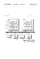
- FIG. 3is a block diagram of an on-chip system bus according to the present invention, particularly illustrating a multiple master/slave environment.
- FIG. 4is a block diagram of a processing device incorporating split transaction tracking and control for interfacing to the on-chip system bus.
- FIG. 5is a timing diagram illustrating use of the split transaction tracking and control on the on-chip system bus of the present invention.
- FIG. 6is a block diagram of multi-master system bus having a cache coherency system according to the present invention.
- FIGS. 7A-Care a table illustrating the address, data, and control lines of the system bus according to the present invention.
- FIG. 8is a timing diagram illustrating the read protocol of the split-transaction on-chip system bus with data release according to the present invention.
- FIG. 9is a block diagram illustrating master devices incorporating split transaction control and cache coherency interfacing to the on-chip system bus of the present invention.
- the computer system 100includes a microprocessor 101 coupled to a memory 122 via a memory controller 120 , via a system bus having separate address lines 110 , data lines 112 , and control lines 114 . Also coupled to the system bus is a graphics controller 130 , and a DMA controller 132 , the DMA controller 132 coupling other device(s) 134 to the system bus. Finally, a bus arbiter 140 is shown, coupled to the system bus, to arbitrate access to both the address bus 110 , and the data bus 112 , between the competing bus master devices 101 , 120 , 130 and 132 .
- system bus of FIG. 1may be either an on-chip or off-chip system bus depending on the solution required.
- system bus as shownpresents each device coupled directly to each of the address/data/control buses 110 , 112 , 114 .
- the illustration of FIG. 1is exemplary only.
- the separate buses 110 , 112 , 114may connect to distinct devices, in a point-to-point fashion.
- the structure of the system bus in FIG. 1simply provides a convenient illustration of how distinct devices communicate with one another over address/data/control lines.
- bus interface 104with separate address 106 and data 108 portions, for interfacing the microprocessor 101 to the address and data lines 110 , 112 of the system bus.
- the bus interface 104is coupled to core logic 102 for executing instructions retrieved by the microprocessor 101 .
- the bus interface 104is required to perform a bus cycle using the address, data, and control lines 110 - 114 .
- the microprocessor 101places an address corresponding to the target memory (or I/O) address on the address lines 110 .
- the microprocessor 101indicates the type of bus cycle it is initiating by placing a pattern on the control lines 114 .
- Exemplary bus cycle typesinclude reads and writes to memory or I/O.
- the memory 120will place the data stored at the target address on the data lines 112 .
- the data portion 108 of the bus interface 104will see the data on the data lines 112 and will latch the data for use by the core logic 102 .
- the processor 101must first gain access to the address bus 110 by asserting “address bus request” to the arbiter 140 .
- the bus arbiter 140asserts “address bus grant” to the processor 101
- the processor 101can drive the address onto the address bus 110 (and the control information onto the control bus 114 ).
- the memory controller 120provides the data associated with the request on the data bus 112 .
- the memory controllercan begin driving the data, it must obtain mastership of the data bus. It does so by asserting “data bus request” to the arbiter 140 .
- the arbiter 140asserts “data bus grant”, the memory controller 120 can begin driving the data.
- FIG. 2provides a timing diagram 200 that illustrates a memory read bus cycle for the computing system 100 described above.
- a clock signalis shown that is the clock for the system bus.
- Addresses on address lines 110are shown as an address signal.
- Data on data lines 112are shown as a data signal.
- the processor 101In performing a memory read, the processor 101 asserts an address bus request during clock cycle 1 .
- the bus arbiter 140sees the address bus request, and since the address bus is not currently busy, it asserts address bus grant at clock cycle 3 .
- the processor 101sees that the arbiter 140 has granted it mastership of the address bus 110 in clock cycle 4 , and so, in clock cycle 5 , drives the address associated with the bus cycle onto the address bus 110 .
- the memory controller 120sees the memory read in clock cycle 6 , obtains the requested data, and asserts data bus request in clock cycle 7 .
- the bus arbiter 140sees the data bus request at clock cycle 8 , and since the data bus is not currently busy, it asserts data bus grant in clock cycle 9 .
- the memory controller 120sees the data bus grant in clock cycle 10 , and drives data onto the data bus 112 during clock cycle 11 .
- the processor 101sees the data on the data bus 112 and latches it into the data portion 108 of the bus interface 104 . This completes the read bus cycle for the processor 101 .
- the discussion belowdescribes novel aspects of the present invention as embodied within an On-Chip System (OCS) Bus.
- OCSOn-Chip System
- the OCS Busis a scalable split-transaction bus for interfacing multiple masters in an on-chip environment.
- the OCS Busprovides a synchronous interface to a de-multiplexed split transaction bus, having a 36-bit address bus, 4 to 16 bits of byte mask depending on the size of the data bus, and either a 32, 64 or 128-bit data bus.
- the arbitration for the address and data busesis independent, with the arbiter being central (one per bus).
- the arbiterconsiders all the incoming bus requests and decides a winner based upon the implemented algorithm. In the simplest instance, the arbiter does round robin scheduling of all the requesting masters.
- the complexity of the arbitration algorithmcan vary depending on the performance requirements of the system.
- the buses and arbiter logicare pipelined, so the arbiter can be granting the bus to the next requester, while the previous winner is using the bus.
- the data portion of the OCS bussupports burst transactions for devices with bursting traffic or higher bandwidth requirements.
- the address businherently only supports single cycle transactions, with the exception of locked read-modify-write operations.
- the protocolalso allows the last-use master to park on the bus, for both buses, while there are no other requesters.
- a block diagram 300is provided illustrating a number of on-chip processing devices in communication with each other via a system bus 310 .
- a central processor 330(having an L 1 cache 332 ) is coupled to the system bus 310 via a bus interface 320 .
- an L 2 cache 334Between the bus interface 320 and the central processor 330 is an L 2 cache 334 .
- the on-chip system bus 310is a multi-master bus, other master devices are shown including: a graphics co-processor 331 (having a cache), a DSP processor 333 (having a cache), and another processor 335 .
- slave devicesare shown attached to the system bus 310 including: DRAM 302 attached via a memory controller 304 ; ROM/SRAM 306 ; and a direct memory access (DMA)/programmable input output (PIO) engine 308 for coupling peripheral I/O devices 311 to the system bus 310 via a peripheral bus 309 .
- DMAdirect memory access
- PIOprogrammable input output
- any of the master devices 330 , 331 , 333 , 335can communicate with the memory controller 304 , ROM/SRAM 306 or the DMA/PIO engine 308 via the system bus 310 , albeit at different times.
- the master devices 330 , 331 , 333 , and 335may have resources within them (such as a cache) that may be accessed by the other master devices. That is, a device may be a master device for some transactions and a slave device for other transactions.
- bus arbitration logic 339coupled to the system bus 310 is bus arbitration logic 339 .
- the bus arbitration logicis responsible for receiving bus master requests for either the address bus or the data bus, and for providing bus grant signals to the requesters according to a predetermined arbitration algorithm.
- the protocol for requesting mastership of the address and data buseswill be further described below. First however, a detailed description will be provided for the split-transaction logic that is embodied within the on-chip OCS bus, according to the present invention, so that the reader will better understand the novelty of the coherency mechanism described below with reference to FIG. 6 .
- the system bus 310 of the present inventionprovides a split transaction bus. That is, the master devices do not have to wait for a request to be completed before issuing a new request. Rather, the masters, on the address/control lines of the system bus 310 , are allowed to make requests before the data portions associated with their requests complete. In addition, the masters receive and process requests even when they are waiting on completion of prior requests. This is accomplished by separating the request and the reply portions of transactions. By de-coupling the request portion of a transaction, from the reply portion of the transaction, latencies typically associated with waiting on the reply portion to complete are eliminated.
- a mastertags each request that is made on the system bus 310 when it issues.
- a slave devicesends the tag back to the requesting master with the data.
- the writing mastersends the written data with the same tag it used when it issued the Write control.
- a portion of the tagis used to identify the requesting device.
- FIG. 4a block diagram 400 is provided of a microprocessor 401 incorporating aspects of the present invention. Elements similar to those described in FIG. 1 above are shown with the same reference numbers, the hundreds digit being replaced with a 4.
- the processor 401includes split transaction tracking & control 440 coupled to the core logic 402 and the bus interface 404 .
- the split transaction tracking and control 440is embodied within the bus interface 404 within the processor 401 , although this is not a requirement.
- the split transaction logic 440is at least one transaction buffer 442 .
- the buffer 442provides temporary storage for transactions awaiting response.
- the transaction id'sare 8-bits in width: a 5-bit transaction ID 444 and a 3-bit master device ID 446 .
- a 5-bit transaction ID 444as many as 32 outstanding requests may exist on the system bus 410 (with a transaction buffer of up to 32 entries).
- a 3-bit master device ID 446as many as 8 different master devices may be indicated.
- the transaction buffer 442may be implemented with a 32 entry table (i.e., one entry per outstanding transaction).
- a target addressis placed on address lines of the system bus 410 . Note: particular definitions of each of the lines on the system bus 410 are provided below with reference to FIG. 9 .
- the split transaction tracking and control 440provides a transaction ID that is associated with the request.
- this idis generated by concatenating the current requester's id with the index of the transaction buffer entry that will hold the request until a response is returned.
- the transaction IDis then placed on the ID control lines (described further below) of the system bus 410 .
- a timing diagram 500is provided illustrating split transaction requests/replies.
- request 1is placed on the control lines of the system bus 410 to indicate a read.
- the split transaction tracking & control 440places a transaction ID of 1 , for example, on the ID lines of the system bus 410 .
- the address portion 406 of the bus interface 404places the target address associated with the request on the address lines of the system bus 410 .
- the address and control lines of the system bus 410are free to perform another transaction. This is true even though the reply associated with request 1 has not completed.
- the processordoes not have to wait 6-8 cycles before beginning another request. Rather, the processor 401 can immediately make another request, if needed.
- the processor 401makes 3 back to back requests. Beginning in clock cycle 2 , the processor 401 issues request 2 on the control lines of the system bus 410 . In addition, the split transaction tracking & control 440 provides a transaction ID of 2 to the bus interface, which is presented on the ID lines of the system bus 410 . At the end of clock cycle 2 , the address and control lines are free to perform another request.
- the processor 401issues request 3 on the control lines of the system bus 410 .
- the split transaction and control 440provides a transaction ID of 3 to be presented on the ID lines of the system bus 410 .
- the target address associated with request 3is also presented on the address lines of the system bus 410 .
- the address and control linesare free to perform another transaction.
- data associated with request 1is placed on the data lines of the system bus 410 .
- the datais being provided by memory external to the processor 401 , or by the slave device responsible for the data.
- the transaction ID associated with request 1is placed on the data ID lines of the system bus 410 to identify the data with its associated transaction.
- the bus interface 404 of the processor 401detects the data, and its associated transaction ID. Since the transaction ID indicates the master device ID, the processor 401 knows that it is the requester. So, the processor 401 latches the data in the data portion 408 of the bus interface 404 .
- the transaction tagis then provided to the split transaction & control 440 .
- the split transaction & control 440is then responsible for associating the data according to the target address of request 1 .
- the data linesare free to be used by another device on the OCS bus 410 .
- data associated with request 2is placed on the data lines of the system bus. Again, along with the data, its associated transaction tag is placed on the ID lines of the system bus.
- the processorrecognizes that it was the requester of the data, and latches the data in the data portion 408 of the bus interface 404 .
- the split transaction & control 440is then responsible for associating the data according to the target address of request 2 .
- a master devicerequests data that is already present within its cache
- activity on the system busmay be eliminated. That is, if the processor 401 contains a cache, and a read is initiated to an area of memory that resides in the cache, the read is provided entirely within the processor 401 without requiring that the processor request mastership of the address bus, etc.
- a masterWhen a master wants to use the address bus, it sends a request signal to the address bus arbiter.
- the arbitergrants the bus based on its arbitration algorithm.
- the masterasserts the lock signal when it wants the address bus for two consecutive cycles (r ⁇ w).
- the master's bus interfacesends three other pieces of information to the address bus arbiter: the transaction type MAA_type[ 1 : 0 ], the target slave id MAA_slaveid[ 2 : 0 ] of the prospective transaction, and the priority of the transaction MAA_pri[ 1 : 0 ].
- the transaction type and slave idwould be used by an arbiter in a system that wants to minimize wasted cycles on the bus. That is, the arbiter also maintains a set of credit counters for the slaves, and checks credit status before granting the request from a master targeted to a particular slave for a specific transaction type. With this type of arbitration, the arbiter must be designed to prevent starvation and to be fair. For more information on the credit counters used, the reader is directed to U.S. Ser. No. 09/373,091, entitled “SCALABLE ON-CHIP BUS”.
- the priority bitsare used if the arbiter implements a priority based arbitration algorithm, such as round robin arbitration at different priority levels.
- the two bits of priorityallow the implementation of 4 priority levels.
- the simplest arbitercould ignore the priority bits and assume that all requests are at the same level and implement a round robin algorithm among all the masters.
- a more complex arbitermight implement two priority levels and hence ignore one of the two priority bits, and implement round robin among the two levels. That is, as long as there are requests at the higher priority level, they are granted and requests at the lower priority level must wait until there are no requests pending at the higher level.
- a configuration bit (not shown) in each bus interfacespecifies the number of priority levels that the arbiter in the current implementation will accept.
- the address busconsists of 65 signals (for a 64-bit data bus). These include AB_addr[ 33 : 0 ] for the address. The lower 2 bits of the address are not needed since the data bus width is 8 bytes and byte addresses are used on the bus.
- One mask bit per data byteprovides the data byte mask, with an 8-bit byte mask for 8 data bytes (or 16 bytes wide with 16 bits of bytemask, or 4 bytes wide with 4 bits of bytemask).
- This systemuses 34 bits to address a 36-bit wide address. Other systems may use wider addresses. In such systems, this expanded addressing capability can be accommodated by simply expanding the width of the address lines.
- the transaction id AB_trid[ 7 : 0 ]consists of 3 bits of master id to uniquely specify the master that originated the transaction, and 5 bits of transaction id, to uniquely track up to 32 outstanding transactions from a specific master.
- the AB_bytemask fieldis used to indicate the position and size of data on the 8 byte wide data bus (assuming a 64-bit data bus, 8 bits of byte mask are required). If all the AB_bytemask bits are zero, this implies a full data bus width transaction. If any of these bits are not zero, then the position and number of the zero bits indicate the position and size of the data in the total width.
- a transactionis said to stream data when a single address is used to transmit more than one cycle of data on the data bus. When streaming data, not all bytemask values are valid.
- a generator of datauses the data bus to transmit the data to a sink, who accepts the data.
- the basic data bus protocolis a little different from the address bus protocol. The main differences are: the explicit use of a release signal by a source to relinquish the data bus (described further below); multi-cycle burst transactions; and no separate flow control for data bus transactions. Rather, the flow control of data bus transactions are implicitly tied to address transactions.
- a slave configuration register(discussed above in FIG. 7) holds the length of bursts supported by a slave per address transaction for write operations.
- a mastermust guarantee buffer space for read-return data from a slave.
- the initial steps of the request-grant-data-release protocol sequenceworks as it did for the address bus. That is, when a source wants to use the bus it asserts a request signal MDA_req to the data bus arbiter.
- the arbitergrants the request DAM_gnt two cycles or later. Two cycles after the source sees grant, it begins to use the data bus. Once the source obtains the data bus, it can continue to use it until the arbiter takes away grant. After the arbiter takes away grant, the source can continue to hold the data bus until it completes its current transaction. During its last cycle of use of the data bus, the source asserts the release signal DB_release. This implies that the data bus is available for use by another source two cycles after the release signal.
- the cycle after releaseis the bus turn around cycle.
- the arbiterasserts grant for a cycle and deasserts it while asserting it to the next source.
- the second sourcecannot use the data bus until it sees the release signal from the current source on the bus.
- the arbiterneeds to keep the grant signal asserted at the second source until the first source releases the bus.
- the basic non-coherent operationsare Read, Write, Interrupt, and Idle. These are used with the designated slave id field in the address bus, i.e., the specific targeted slave responds to the operation. In the case of Idle, no slave responds.
- the Idle operationis used when a master has acquired the address bus, but is unable to use it because of flow control or other reasons.
- the interrupt operationis used to set or reset an interrupt register in a specific target device designated by the slave id field.
- the Read and Writeare non-coherent read and write operations.
- the Write-barrieris used by a master in a Read-Modify-Write atomic transaction.
- a separate write command typeis used by the slave to understand that the master intends this write to act as a barrier and to ensure that all operations to the same address from all masters do not bypass this write.
- For a complete description of Write-barrierplease see U.S. Ser. No. 09/373,092 entitled “LOCKED READ/WRITE ON SEPARATE ADDRESS/DATA BUS USING WRITE BARRIER”.
- the Read-impl and Write-implare provided as slots where implementation specific read and write operations can be used.
- the reset signalis asserted and the entire bus interface unit resets all its state.
- the error signaling operationsare used to designate the possible source of error in the system before pulling reset, so a record can be made by a bus monitoring device of the possible source of problems in the system.
- the table belowillustrates the operation of the OCS bus for coherent operations. Designations are as follows: d-dirty, c-clean, i-invalid, s-shared, e-exclusive, as possible cache states, and wb for writeback.
- 010 Coherent-ackDo nothing The memory controller initiates this to indicate the completion of a coherent operation to the initiator when no data writeback was done (which would have been used by the initiator as an ack otherwise). 011 Reserved 100 Read-non- If [d], wb and Put wb data if any into exclusive modify [e] to memory, also picked up ([s] in [s] by the initiator. If initiator's no wb data, read data cache) from memory and send to initiator.
- FIG. 6a block diagram 600 is provided of a multi-master environment incorporating the cache coherency mechanism of the present invention.
- Three master devices 630 , 631 and 633are shown coupled to a memory controller 604 via the OCS bus 610 .
- the memory controller 604couples the main memory (DRAM) 602 to all of the devices on the OCS bus 610 .
- DRAMmain memory
- a cache coherency system 660is provided within each of the master devices. Details of the cache coherency system 660 are illustrated with particular reference to master device 630 .
- a cache 662Within the cache coherency system 660 are a cache 662 a coherency input buffer 664 , and a coherency credit counter 666 .
- a read counter 668 and a write counter 669External to the coherency system 6 60 are a read counter 668 and a write counter 669 .
- the read counter 668 and the write counter 669are part of the credit based flow control system mentioned above with respect to the Address Bus Protocol. As referenced in that section, for more information on the credit based flow control used in the OCS bus, the reader is directed to U.S. Ser. No. 09/373,091, entitled “SCALABLE ON-CHIP SYSTEM BUS.
- the OCS bus protocolrequires that all systems using coherent operations implement their devices with caches with a pre-designated coherency input buffer 664 to hold only coherent transactions.
- the size of the buffer 664must be built to suit the performance requirements of the system configuration in question, provided the size is identical for all devices 630 , 631 , 633 .
- the coherency credit counter 666is added to all master interface blocks for coherent operations.
- the credit counter 666must be checked by the master 630 before initiating a coherent operation.
- the initiator of coherent operationsmust also check the memory controller's 604 read address buffer counter 668 (assuming that the memory controller does not implement a separate coherent-operations-only buffer).
- the coherency operation credit countersare decremented whenever a coherent operation is initiated on the bus, and it is incremented when an explicit credit signal is asserted by the coherency buffer management logic 670 of the memory controller (which acts as the designated central controller of all coherency operations).
- the memory controller's 604 write address counter 669must also be checked.
- Each device with a cachesends two bits of state signal to the memory controller 604 in response to a coherent operation.
- the two bits of stateare dirty, clean, invalid, or don't-know-yet.
- the don't-know-yetis used to indicate that the device is still busy and unable to read out its cache state. Since these two bits of state are a side-band communication and do not carry any transaction id information, each device must respond to coherent operations in the order received.
- the coherent-ack operationis used by the memory controller 604 to acknowledge the completion of a probe coherent operation that has no data return associated with it.
- a coherent operationhas a data return associated with it, the data itself acts as an acknowledgement of the completion of the operation.
- a master 630 , 631 , 633 that wishes to initiate a coherent operationchecks the coherency credit counter 666 for positive credit. In addition, it checks the read and write address (for write-back data) counters 668 , 669 for the memory controller 604 . When all these counters indicate available resources, the master can put out its request, for example a writeback-invalidate operation.
- All devices with cachesverify the type of operation and enter it into their coherency input buffer 664 . (If the operation is coherent, the target slave id is ignored). The operation is also recorded by the memory controller 604 , which is going to co-ordinate all the responses and send an acknowledgement back to the original initiator, if needed.
- All devicesrespond to the memory controller 604 with their state, i.e., dirty, clean, invalid, or don't-know-yet. If a particular device responds with dirty, that device will follow up with the dirty data on the data portion of the OCS bus 610 . On the data portion, it uses the transaction id used by the original initiator. Except in the case of Write-exclusive, the initiator is able to pick up the writeback data. A device response with either clean or invalid is accepted by the memory controller 604 without the expectation of any other communication. A response of don't-know-yet implies that the device is still busy and unable to check its status. In this situation, the memory controller 604 must wait until the device can respond.
- statei.e., dirty, clean, invalid, or don't-know-yet.
- the memory controllercan respond to the original initiator acknowledging that the Writeback-invalidate operation is complete. This acknowledge is needed only if there was no dirty writeback data. To do this, the memory controller 604 uses an address bus operation with the originator's transaction id and the operation Coherent-ack, which is a non-coherent operation that requires no checking of credit counters by the memory controller before sending on the address bus.
- a table 700is shown that illustrates Address, Data and Control signals according to the OCS bus of the present invention.
- This Figureshows: 17 signal lines for address bus arbitration (plus 2 credit/debit signals per slave); 8 signal lines for data bus arbitration (plus additional signals for each master in a system); 61-74 address bus signals (depending on the size of the data bus); 47-151 signals for data bus signals (depending on the size of the data bus); and 3 signal lines for coherency.
- the OCS bus interface illustrated in table 700is partitioned into three sub-interfaces, each of which operates independently from the others.
- the OCS bus interface 604consists of separately controlled Address, Data and Coherence interfaces.
- the address and the data interfacesare independent, and each can be in either a master or slave state at any time regardless of the state of the other.
- the masterdrives the bi-directional address interface signals and is permitted to issue master requests to the OCS bus.
- the masterdoes not drive the bi-directional address interface signals and accepts external requests from the OCS bus.
- the masterdrives the bi-directional data interface signals and is permitted to send write-back, store or response data to the OCS bus.
- slave statethe master does not drive the bi-directional data interface signals and accepts data responses from the OCS bus.
- the coherence interfacedoes not have any bi-directional signals. It is always in master state and driven by the master.
- the Masterthat wants to read, requests the address bus arbiter for the address bus. It signals the id of the target slave, a priority, and the type of operation, i.e., Read. In addition, if the Read is a coherent operation, the master checks the coherency credit counter, and the read/write counters for the memory controller for positive credit.
- the arbiterissues a grant to the requesting Master. This grant is based on whether the Master has received its turn in the arbitration scheme per its priority level. On receiving grant, the Master can drop its request line, or keep it asserted if it has another request that it needs to make.
- the Masterputs the read address out on the address bus. If the transaction is a coherent read, all the devices with a cache respond to the memory controller with their state, as described above.
- the SlaveWhen the Slave is ready with the read data, it requests the data bus from the data bus arbiter along with a priority. It uses the same priority bits that it obtained from the master during the address transaction.
- the data bus arbitergrants the data bus to the slave per the arbitration logic.
- the Slaveputs the first 8 bytes of data out on the data bus when it has seen Release and has grant. As mentioned above, if the transaction is a coherent read, it is possible that the master would obtain the data earlier, such as when another master device is writing back dirty data. In this instance, the memory controller 604 would not present the requested data subsequent to the writeback.
- a timing diagram 800is presented illustrating the read protocol on the OCS bus.
- the control signals in FIG. 8are presented as active HIGH.
- a readis shown to begin when a processor requests access to the address bus by asserting MAA_req at clock cycle 1 .
- the arbitergrants the processor access to the address bus by asserting AAM_gnt.
- the processorinitiates a read by indicating a read command on AB_cmd. While not shown, it should be understood that the processor also presents the address of the read on the address lines of the OCS bus. Also shown at clock cycle 5 is the data release line DB_release. This indicates that another device that is responding to a previous request is completing the request and releasing the data bus.
- the processor P 0becomes master of the address bus, and drives a read command Rd 1 on the command lines.
- the processor P 0drives the address associated with Rd 1 on the address lines of the OCS bus, and places the transaction ID associated with the request on SysCmdID.
- the slave devicethat is the target of the read, requests access to the data bus by asserting SDA_req.
- the arbitergrants the slave access to the data bus by asserting DAS_gnt. Note, since the data bus is inactive when the slave requested access, grant is asserted two clock cycles after the request is made.
- the slave devicebegins driving data on the data bus.
- the slave devicerequires 4 clock cycles to fulfill the read request, and performs the request in a 4 cycle burst.
- the slave devicewas able to begin transferring data 2 cycles after seeing assertion of DAS_gnt since it had already recorded assertion of DB_release in clock cycle 5 .
- the slave deviceAt clock cycle n+8, commensurate with the last clock cycle of data transfer, the slave device asserts DB_release indicating that it no longer requires access to the data bus.
- FIG. 9a block diagram 900 is shown of processors 901 , 902 that incorporate the novel bus features of the present invention.
- the processors 901 , 902are coupled to other devices 904 , 906 , and 908 , through a bus interface 990 via a system bus 910 .
- the processors 901 , 902each have a split transaction tracking and control 940 with a transaction ID register 942 .
- the processorsinclude a cache coherency system 960 .
- Each of the elements shown in FIG. 900operate as described above with reference to FIGS. 4-6.
- the inventioncan also be embodied in an article of manufacture comprised of a computer usable medium configured to store a computer-readable program code.
- the program codecauses the enablement of the functions or fabrication, or both, of the hardware disclosed in this specification. For example, this might be accomplished through the use of general programming languages (e.g., C, C++, and so on), hardware description language (HDL), register transfer languages (RTL), Verilog HDL, VHDL, AHDL (Altera Hardware Description Language), or other programming and/or circuit (i.e., schematic) capture tools available in the art.
- HDLhardware description language
- RTLregister transfer languages
- Verilog HDLVerilog HDL
- VHDLregister transfer languages
- AHDLAltera Hardware Description Language
- a book entitled “A Verilog HDL Primer” by J. Bhasker, Star Galaxy Pr., 1997provides greater detail on Verilog HDL, and is incorporated herein by reference in its entirety for all purposes.
- bus of the present inventionhas been particularly described with reference to a master processor and a slave.
- any type of devicewhether slave or master (or both slave and master), that requires on-chip access to other devices, may be designed to incorporate the novel features of the present invention by providing an interface to the OCS bus as described above.
- the cache coherency mechanismis particularly described, in combination with coherency buffer management within the memory controller.
- the coherency buffer managementmay be placed in another device, or may be eliminated altogether if point to point routing between master devices is desired.
- bus of the present inventionhas been particularly described with reference to an on-chip bus.
- novel aspects of the bus, as described abovemay be implemented either partially, or entirely off chip, without departing from the solution provided by the present invention.
Landscapes
- Engineering & Computer Science (AREA)
- Theoretical Computer Science (AREA)
- Physics & Mathematics (AREA)
- General Engineering & Computer Science (AREA)
- General Physics & Mathematics (AREA)
- Memory System Of A Hierarchy Structure (AREA)
Abstract
Description
| Ser. No. | Title |
| 09/373,091 | SCALABLE ON-CHIP SYSTEM BUS |
| 09/373,092 | LOCKED READ/WRITE ON SEPARATE |
| ADDRESS/DATA BUS USING WRITE BARRIER | |
| 09/373,093 | DATA RELEASE TO REDUCE LATENCY IN ON- |
| CHIP SYSTEM BUS | |
| 09/373,095 | BURST-CONFIGURABLE DATA BUS |
| Operation of | Operation of | ||
| AB_cmd | Operation | devices with a | the memory |
| [4:0] | Name | Cache | controller |
| 001 | Write-barrier | Do nothing | The slave that is the |
| (non- | target of this | ||
| coherent) | transaction treats this | ||
| write as a barrier and | |||
| does not allow any | |||
| other transaction to | |||
| the same address (from | |||
| any Master), to bypass | |||
| this write. | |||
| 010 | Reserved | ||
| 011 | |||
| 100 | Read (non- | If target (slave | If target (slave id |
| coherent) | id match), | match), returns data | |
| returns data | directly from memory to | ||
| directly from | initiator. | ||
| cache to | |||
| initiator. | |||
| 101 | Write (non- | If target (slave | If target, write data |
| coherent) | id match), | directly into memory | |
| writes data | |||
| directly into | |||
| cache. | |||
| 110 | Interrupt | If target, | |
| set/reset some | |||
| interrupt | |||
| register on | |||
| device | |||
| 111 | Idle | Do nothing. | Do nothing. |
| 01000 | Read-impl | Implementation specific type of read, if |
| required | ||
| 01001 | Write- | Implementation specific type of write, if |
| impl | required | |
| 01010 | Reserved | |
| 01011 | Error | Encode error-type in the low two bits of |
| AB_bytemask field, i.e., | ||
| AB-bytemask [1:0] | ||
| 00 - Master error | ||
| 01 - Slave error | ||
| 10 - Address-bus arbiter error | ||
| 11 - Data bus arbiter error | ||
| Encode id of error device for Master and | ||
| Slave in AB_slaveid | ||
| 01100 | EJTAG | |
| 01101 | ||
| 01110 | ||
| 01111 | ||
| Operation of | Operation of | ||
| AB_cmd | Operation | devices with a | the memory |
| [4:0] | Name | Cache | controller |
| 10000 | Writeback- | If [d], wb and | Put wb data if any into |
| downgrade | modify to [s] | memory, also picked up | |
| by the initiator. If | |||
| no wb, ack initiator | |||
| with a coherent-ack | |||
| operation on the | |||
| address bus (after all | |||
| cache devices have | |||
| responded). | |||
| 001 | Writeback- | If [d], wb and | Put wb data if any into |
| invalidate | if [c or d] | memory, also picked up | |
| modify to [i] | by initiator. And if | ||
| none, ack initiator | |||
| after all devices have | |||
| responded. | |||
| 010 | Coherent-ack | Do nothing | The memory controller |
| initiates this to | |||
| indicate the completion | |||
| of a coherent operation | |||
| to the initiator when | |||
| no data writeback was | |||
| done (which would have | |||
| been used by the | |||
| initiator as an ack | |||
| otherwise). | |||
| Reserved | |||
| 100 | Read-non- | If [d], wb and | Put wb data if any into |
| exclusive | modify [e] to | memory, also picked up | |
| ([s] in | [s] | by the initiator. If | |
| initiator's | no wb data, read data | ||
| cache) | from memory and send | ||
| to initiator. | |||
| 101 | Reserved | ||
| 110 | Reserved | ||
| 111 | Reserved | ||
| 11000 | Read- | If [d], wb and | This is used when the |
| exclusive- | if [c or d], | initiator knows it is | |
| probe ([c] in | modify to [i] | going to write the | |
| initiator's | whole line into its | ||
| cache) | cache, so there is no | ||
| need to send data. But | |||
| the initiator does not | |||
| have the cache line, so | |||
| it allocates a cache | |||
| line for the data in | |||
| [e] mode (with wb data | |||
| if it exists or with | |||
| junk value). If no wb | |||
| data, memory controller | |||
| acks the initiator when | |||
| all other devices have | |||
| responded. | |||
| 11001 | Upgrade- | If [d], wb | The difference between |
| probe ([e] | (shouldn't | this and read- | |
| in initiator's | happen) and if | exclusive-probe is that | |
| cache) | [c or d], modify | in this case, the data | |
| to [i] | already exists in the | ||
| initiator's cache in | |||
| [s] mode and it wants | |||
| to upgrade to [e]. | |||
| When all devices have | |||
| responded, ack the | |||
| initiator. | |||
| 11010 | Reserved | ||
| 11011 | Reserved | ||
| 11100 | Read- | If [d], wb and | Wait for all devices to |
| exclusive | if [c or d], | respond and if wb the | |
| modify to [i] | initiator picks up the | ||
| data. If no wb, read | |||
| memory and send back | |||
| data to initiator. | |||
| 11101 | Write- | If [d], wb and | (Used when initiator |
| exclusive | if [c or d], | does partial cache-line | |
| modify to [i] | write and wants the | ||
| memory controller to | |||
| merge this with the | |||
| rest of the dirty | |||
| data). Merge write | |||
| data from initiator | |||
| with wb data and write | |||
| into memory. IN this | |||
| case the initiator does | |||
| not pick up wb data. | |||
| 11110 | Reserved | ||
| 11111 | Reserved | ||
Claims (39)
Priority Applications (1)
| Application Number | Priority Date | Filing Date | Title |
|---|---|---|---|
| US09/373,094US6681283B1 (en) | 1999-08-12 | 1999-08-12 | Coherent data apparatus for an on-chip split transaction system bus |
Applications Claiming Priority (1)
| Application Number | Priority Date | Filing Date | Title |
|---|---|---|---|
| US09/373,094US6681283B1 (en) | 1999-08-12 | 1999-08-12 | Coherent data apparatus for an on-chip split transaction system bus |
Publications (1)
| Publication Number | Publication Date |
|---|---|
| US6681283B1true US6681283B1 (en) | 2004-01-20 |
Family
ID=30000397
Family Applications (1)
| Application Number | Title | Priority Date | Filing Date |
|---|---|---|---|
| US09/373,094Expired - LifetimeUS6681283B1 (en) | 1999-08-12 | 1999-08-12 | Coherent data apparatus for an on-chip split transaction system bus |
Country Status (1)
| Country | Link |
|---|---|
| US (1) | US6681283B1 (en) |
Cited By (37)
| Publication number | Priority date | Publication date | Assignee | Title |
|---|---|---|---|---|
| US20030065844A1 (en)* | 2001-09-28 | 2003-04-03 | Lester Robert A. | Method for improving processor performance |
| US20030105828A1 (en)* | 2001-11-20 | 2003-06-05 | Broadcom Corp. | Systems using Mix of packet, coherent, and noncoherent traffic to optimize transmission between systems |
| US20030204663A1 (en)* | 2002-04-30 | 2003-10-30 | Stuber Russell B. | Apparatus for arbitrating non-queued split master devices on a data bus |
| US20040062259A1 (en)* | 2002-09-27 | 2004-04-01 | International Business Machines Corporation | Token-based active queue management |
| US20040100907A1 (en)* | 2002-11-25 | 2004-05-27 | Illikkal Rameshkumar G. | Managing a protocol control block cache in a network device |
| US20040267992A1 (en)* | 2002-02-28 | 2004-12-30 | Stuber Russell B | Look ahead split release for a data bus |
| US6857035B1 (en)* | 2001-09-13 | 2005-02-15 | Altera Corporation | Methods and apparatus for bus mastering and arbitration |
| US20050223129A1 (en)* | 2004-04-02 | 2005-10-06 | Arm Limited | Arbitration of data transfer requests |
| US7287139B2 (en) | 2004-07-23 | 2007-10-23 | International Business Machines Corporation | Maintenance of persistent data using bitmaps |
| US20080320232A1 (en)* | 2007-06-22 | 2008-12-25 | Mips Technologies Inc. | Preventing Writeback Race in Multiple Core Processors |
| US20080320231A1 (en)* | 2007-06-22 | 2008-12-25 | Mips Technologies Inc. | Avoiding Livelock Using Intervention Messages in Multiple Core Processors |
| US20090083493A1 (en)* | 2007-09-21 | 2009-03-26 | Mips Technologies, Inc. | Support for multiple coherence domains |
| US20090089510A1 (en)* | 2007-09-28 | 2009-04-02 | Mips Technologies, Inc. | Speculative read in a cache coherent microprocessor |
| US20090089468A1 (en)* | 2007-09-28 | 2009-04-02 | Nagabhushan Chitlur | Coherent input output device |
| US7549004B1 (en)* | 2004-08-20 | 2009-06-16 | Altera Corporation | Split filtering in multilayer systems |
| US20090157981A1 (en)* | 2007-12-12 | 2009-06-18 | Mips Technologies, Inc. | Coherent instruction cache utilizing cache-op execution resources |
| US20090248988A1 (en)* | 2008-03-28 | 2009-10-01 | Mips Technologies, Inc. | Mechanism for maintaining consistency of data written by io devices |
| US7849208B2 (en) | 2002-08-30 | 2010-12-07 | Broadcom Corporation | System and method for TCP offload |
| US7911952B1 (en)* | 2002-07-12 | 2011-03-22 | Mips Technologies, Inc. | Interface with credit-based flow control and sustained bus signals |
| US7912064B2 (en) | 2002-08-30 | 2011-03-22 | Broadcom Corporation | System and method for handling out-of-order frames |
| US7934021B2 (en) | 2002-08-29 | 2011-04-26 | Broadcom Corporation | System and method for network interfacing |
| US8116203B2 (en) | 2001-07-23 | 2012-02-14 | Broadcom Corporation | Multiple virtual channels for use in network devices |
| US8135016B2 (en) | 2002-03-08 | 2012-03-13 | Broadcom Corporation | System and method for identifying upper layer protocol message boundaries |
| US8180928B2 (en) | 2002-08-30 | 2012-05-15 | Broadcom Corporation | Method and system for supporting read operations with CRC for iSCSI and iSCSI chimney |
| US8402142B2 (en) | 2002-08-30 | 2013-03-19 | Broadcom Corporation | System and method for TCP/IP offload independent of bandwidth delay product |
| US20130117511A1 (en)* | 2011-11-08 | 2013-05-09 | Arm Limited | Data processing apparatus and method |
| US20140101390A1 (en)* | 2012-10-08 | 2014-04-10 | Wiscosin Alumni Research Foundation | Computer Cache System Providing Multi-Line Invalidation Messages |
| US8750320B2 (en) | 1997-01-23 | 2014-06-10 | Broadcom Corporation | Fibre channel arbitrated loop bufferless switch circuitry to increase bandwidth without significant increase in cost |
| US8798091B2 (en) | 1998-11-19 | 2014-08-05 | Broadcom Corporation | Fibre channel arbitrated loop bufferless switch circuitry to increase bandwidth without significant increase in cost |
| US20150234738A1 (en)* | 2014-02-19 | 2015-08-20 | Rambus Inc. | Memory System With Activate-Leveling Method |
| US20160321179A1 (en)* | 2015-04-30 | 2016-11-03 | Arm Limited | Enforcing data protection in an interconnect |
| US20170031854A1 (en)* | 1999-10-19 | 2017-02-02 | Rambus Inc. | Flash memory controller with calibrated data communication |
| US10042692B1 (en)* | 2015-09-29 | 2018-08-07 | Xilinx, Inc. | Circuit arrangement with transaction timeout detection |
| US10248567B2 (en)* | 2014-06-16 | 2019-04-02 | Hewlett-Packard Development Company, L.P. | Cache coherency for direct memory access operations |
| US10452544B1 (en)* | 2017-09-27 | 2019-10-22 | EMC IP Holding Company LLC | Using persistent memory technology as a host-side storage tier for clustered/distributed file systems, managed by host-side tier |
| CN110443070A (en)* | 2019-08-12 | 2019-11-12 | 南京芯驰半导体科技有限公司 | More host shared memory systems and data completeness protection method |
| US10606750B1 (en)* | 2010-10-25 | 2020-03-31 | Mallanox Technologies Ltd. | Computing in parallel processing environments |
Citations (40)
| Publication number | Priority date | Publication date | Assignee | Title |
|---|---|---|---|---|
| US4587609A (en) | 1983-07-01 | 1986-05-06 | Honeywell Information Systems Inc. | Lockout operation among asynchronous accessers of a shared computer system resource |
| US4998198A (en) | 1988-04-07 | 1991-03-05 | Tandem Computers Incorporated | Dynamic burst control for data transfers |
| US5091846A (en) | 1986-10-03 | 1992-02-25 | Intergraph Corporation | Cache providing caching/non-caching write-through and copyback modes for virtual addresses and including bus snooping to maintain coherency |
| US5255378A (en) | 1989-04-05 | 1993-10-19 | Intel Corporation | Method of transferring burst data in a microprocessor |
| US5347648A (en)* | 1990-06-29 | 1994-09-13 | Digital Equipment Corporation | Ensuring write ordering under writeback cache error conditions |
| US5428753A (en) | 1992-05-15 | 1995-06-27 | Hitachi, Ltd. | Method for controlling a bus to progress transfer cycles without inserting a cycle for acknowledgment |
| US5463762A (en) | 1993-12-30 | 1995-10-31 | Unisys Corporation | I/O subsystem with header and error detection code generation and checking |
| US5504874A (en) | 1993-09-29 | 1996-04-02 | Silicon Graphics, Inc. | System and method of implementing read resources to maintain cache coherency in a multiprocessor environment permitting split transactions |
| US5525971A (en) | 1993-09-23 | 1996-06-11 | Advanced Risc Machines Limited | Integrated circuit |
| US5579530A (en) | 1992-06-11 | 1996-11-26 | Intel Corporation | Method and apparatus for dynamically allocating access time to a resource shared between a peripheral bus and a host bus by dynamically controlling the size of burst data transfers on the peripheral bus |
| US5581782A (en) | 1994-03-01 | 1996-12-03 | Intel Corporation | Computer system with distributed bus arbitration scheme for symmetric and priority agents |
| US5615404A (en) | 1994-10-31 | 1997-03-25 | Intel Corporation | System having independently addressable bus interfaces coupled to serially connected multi-ported signal distributors generating and maintaining frame based polling schedule favoring isochronous peripherals |
| US5696976A (en) | 1990-12-21 | 1997-12-09 | Intel Corporation | Protocol for interrupt bus arbitration in a multi-processor system |
| US5724549A (en)* | 1992-04-06 | 1998-03-03 | Cyrix Corporation | Cache coherency without bus master arbitration signals |
| US5751975A (en) | 1995-12-28 | 1998-05-12 | Intel Corporation | Method and apparatus for interfacing a device compliant to a first bus protocol to an external bus having a second bus protocol and for providing virtual functions through a multi-function intelligent bridge |
| US5768612A (en) | 1994-06-08 | 1998-06-16 | Intel Corporation | Interface allowing use of a non-PCI standard resource on a PCI standard bus |
| US5778412A (en) | 1995-09-29 | 1998-07-07 | Intel Corporation | Method and apparatus for interfacing a data bus to a plurality of memory devices |
| US5781745A (en) | 1996-05-20 | 1998-07-14 | 3Com Corporation | High speed communication bus |
| US5787486A (en) | 1995-12-15 | 1998-07-28 | International Business Machines Corporation | Bus protocol for locked cycle cache hit |
| US5796977A (en) | 1994-03-01 | 1998-08-18 | Intel Corporation | Highly pipelined bus architecture |
| US5799203A (en) | 1996-05-17 | 1998-08-25 | Advanced Micro Devices, Inc. | System for receiving peripheral device capability information and selectively disabling corresponding processing unit function when the device failing to support such function |
| US5802560A (en)* | 1995-08-30 | 1998-09-01 | Ramton International Corporation | Multibus cached memory system |
| US5828865A (en) | 1995-12-27 | 1998-10-27 | Intel Corporation | Dual mode bus bridge for interfacing a host bus and a personal computer interface bus |
| US5832310A (en) | 1993-12-30 | 1998-11-03 | Unisys Corporation | Serial I/O channel having dependent and synchronous sources of control data and user defined data |
| US5859986A (en) | 1997-02-20 | 1999-01-12 | International Business Machines Corporation | Bandwidth efficient method and means for resynchronizing a master and slave over a clocked, arbitrated, bidirectional multistate parallel bus using local data recirculation, wait states, and cycle stealing |
| US5892978A (en) | 1996-07-24 | 1999-04-06 | Vlsi Technology, Inc. | Combined consective byte update buffer |
| US5918072A (en) | 1995-09-18 | 1999-06-29 | Opti Inc. | System for controlling variable length PCI burst data using a dummy final data phase and adjusting the burst length during transaction |
| US5996036A (en) | 1997-01-07 | 1999-11-30 | Apple Computers, Inc. | Bus transaction reordering in a computer system having unordered slaves |
| US6034542A (en)* | 1997-10-14 | 2000-03-07 | Xilinx, Inc. | Bus structure for modularized chip with FPGA modules |
| US6035364A (en) | 1995-11-20 | 2000-03-07 | Advanced Micro Devices, Inc. | Independent use of bits on an on-chip bus |
| US6044225A (en) | 1996-03-13 | 2000-03-28 | Diamond Multimedia Systems, Inc. | Multiple parallel digital data stream channel controller |
| US6085261A (en) | 1996-07-29 | 2000-07-04 | Motorola, Inc. | Method and apparatus for burst protocol in a data processing system |
| US6108734A (en) | 1997-12-01 | 2000-08-22 | Digital Equipment Corporation | Method and apparatus for a relaxed bus protocol using heuristics and higher level supervision |
| US6122690A (en) | 1997-06-05 | 2000-09-19 | Mentor Graphics Corporation | On-chip bus architecture that is both processor independent and scalable |
| US6134481A (en) | 1996-10-31 | 2000-10-17 | Sgs-Thomson Microelectronics Limited | Message protocol |
| US6138176A (en) | 1997-11-14 | 2000-10-24 | 3Ware | Disk array controller with automated processor which routes I/O data according to addresses and commands received from disk drive controllers |
| US6173349B1 (en) | 1996-10-18 | 2001-01-09 | Samsung Electronics Co., Ltd. | Shared bus system with transaction and destination ID |
| US6185637B1 (en) | 1998-04-15 | 2001-02-06 | Advanced Micro Devices, Inc. | System for implementing an adaptive burst length for burst mode transactions of a memory by monitoring response times for different memory regions |
| US6301625B1 (en) | 1997-11-14 | 2001-10-09 | 3Ware, Inc. | System and method for processing and tracking the completion of I/O requests in a disk array system |
| US6321284B1 (en) | 1998-07-27 | 2001-11-20 | Fujitsu Limited | Multiprocessor system with multiple memory buses for access to shared memories |
- 1999
- 1999-08-12USUS09/373,094patent/US6681283B1/ennot_activeExpired - Lifetime
Patent Citations (40)
| Publication number | Priority date | Publication date | Assignee | Title |
|---|---|---|---|---|
| US4587609A (en) | 1983-07-01 | 1986-05-06 | Honeywell Information Systems Inc. | Lockout operation among asynchronous accessers of a shared computer system resource |
| US5091846A (en) | 1986-10-03 | 1992-02-25 | Intergraph Corporation | Cache providing caching/non-caching write-through and copyback modes for virtual addresses and including bus snooping to maintain coherency |
| US4998198A (en) | 1988-04-07 | 1991-03-05 | Tandem Computers Incorporated | Dynamic burst control for data transfers |
| US5255378A (en) | 1989-04-05 | 1993-10-19 | Intel Corporation | Method of transferring burst data in a microprocessor |
| US5347648A (en)* | 1990-06-29 | 1994-09-13 | Digital Equipment Corporation | Ensuring write ordering under writeback cache error conditions |
| US5696976A (en) | 1990-12-21 | 1997-12-09 | Intel Corporation | Protocol for interrupt bus arbitration in a multi-processor system |
| US5724549A (en)* | 1992-04-06 | 1998-03-03 | Cyrix Corporation | Cache coherency without bus master arbitration signals |
| US5428753A (en) | 1992-05-15 | 1995-06-27 | Hitachi, Ltd. | Method for controlling a bus to progress transfer cycles without inserting a cycle for acknowledgment |
| US5579530A (en) | 1992-06-11 | 1996-11-26 | Intel Corporation | Method and apparatus for dynamically allocating access time to a resource shared between a peripheral bus and a host bus by dynamically controlling the size of burst data transfers on the peripheral bus |
| US5525971A (en) | 1993-09-23 | 1996-06-11 | Advanced Risc Machines Limited | Integrated circuit |
| US5504874A (en) | 1993-09-29 | 1996-04-02 | Silicon Graphics, Inc. | System and method of implementing read resources to maintain cache coherency in a multiprocessor environment permitting split transactions |
| US5463762A (en) | 1993-12-30 | 1995-10-31 | Unisys Corporation | I/O subsystem with header and error detection code generation and checking |
| US5832310A (en) | 1993-12-30 | 1998-11-03 | Unisys Corporation | Serial I/O channel having dependent and synchronous sources of control data and user defined data |
| US5581782A (en) | 1994-03-01 | 1996-12-03 | Intel Corporation | Computer system with distributed bus arbitration scheme for symmetric and priority agents |
| US5796977A (en) | 1994-03-01 | 1998-08-18 | Intel Corporation | Highly pipelined bus architecture |
| US5768612A (en) | 1994-06-08 | 1998-06-16 | Intel Corporation | Interface allowing use of a non-PCI standard resource on a PCI standard bus |
| US5615404A (en) | 1994-10-31 | 1997-03-25 | Intel Corporation | System having independently addressable bus interfaces coupled to serially connected multi-ported signal distributors generating and maintaining frame based polling schedule favoring isochronous peripherals |
| US5802560A (en)* | 1995-08-30 | 1998-09-01 | Ramton International Corporation | Multibus cached memory system |
| US5918072A (en) | 1995-09-18 | 1999-06-29 | Opti Inc. | System for controlling variable length PCI burst data using a dummy final data phase and adjusting the burst length during transaction |
| US5778412A (en) | 1995-09-29 | 1998-07-07 | Intel Corporation | Method and apparatus for interfacing a data bus to a plurality of memory devices |
| US6035364A (en) | 1995-11-20 | 2000-03-07 | Advanced Micro Devices, Inc. | Independent use of bits on an on-chip bus |
| US5787486A (en) | 1995-12-15 | 1998-07-28 | International Business Machines Corporation | Bus protocol for locked cycle cache hit |
| US5828865A (en) | 1995-12-27 | 1998-10-27 | Intel Corporation | Dual mode bus bridge for interfacing a host bus and a personal computer interface bus |
| US5751975A (en) | 1995-12-28 | 1998-05-12 | Intel Corporation | Method and apparatus for interfacing a device compliant to a first bus protocol to an external bus having a second bus protocol and for providing virtual functions through a multi-function intelligent bridge |
| US6044225A (en) | 1996-03-13 | 2000-03-28 | Diamond Multimedia Systems, Inc. | Multiple parallel digital data stream channel controller |
| US5799203A (en) | 1996-05-17 | 1998-08-25 | Advanced Micro Devices, Inc. | System for receiving peripheral device capability information and selectively disabling corresponding processing unit function when the device failing to support such function |
| US5781745A (en) | 1996-05-20 | 1998-07-14 | 3Com Corporation | High speed communication bus |
| US5892978A (en) | 1996-07-24 | 1999-04-06 | Vlsi Technology, Inc. | Combined consective byte update buffer |
| US6085261A (en) | 1996-07-29 | 2000-07-04 | Motorola, Inc. | Method and apparatus for burst protocol in a data processing system |
| US6173349B1 (en) | 1996-10-18 | 2001-01-09 | Samsung Electronics Co., Ltd. | Shared bus system with transaction and destination ID |
| US6134481A (en) | 1996-10-31 | 2000-10-17 | Sgs-Thomson Microelectronics Limited | Message protocol |
| US5996036A (en) | 1997-01-07 | 1999-11-30 | Apple Computers, Inc. | Bus transaction reordering in a computer system having unordered slaves |
| US5859986A (en) | 1997-02-20 | 1999-01-12 | International Business Machines Corporation | Bandwidth efficient method and means for resynchronizing a master and slave over a clocked, arbitrated, bidirectional multistate parallel bus using local data recirculation, wait states, and cycle stealing |
| US6122690A (en) | 1997-06-05 | 2000-09-19 | Mentor Graphics Corporation | On-chip bus architecture that is both processor independent and scalable |
| US6034542A (en)* | 1997-10-14 | 2000-03-07 | Xilinx, Inc. | Bus structure for modularized chip with FPGA modules |
| US6138176A (en) | 1997-11-14 | 2000-10-24 | 3Ware | Disk array controller with automated processor which routes I/O data according to addresses and commands received from disk drive controllers |
| US6301625B1 (en) | 1997-11-14 | 2001-10-09 | 3Ware, Inc. | System and method for processing and tracking the completion of I/O requests in a disk array system |
| US6108734A (en) | 1997-12-01 | 2000-08-22 | Digital Equipment Corporation | Method and apparatus for a relaxed bus protocol using heuristics and higher level supervision |
| US6185637B1 (en) | 1998-04-15 | 2001-02-06 | Advanced Micro Devices, Inc. | System for implementing an adaptive burst length for burst mode transactions of a memory by monitoring response times for different memory regions |
| US6321284B1 (en) | 1998-07-27 | 2001-11-20 | Fujitsu Limited | Multiprocessor system with multiple memory buses for access to shared memories |
Cited By (76)
| Publication number | Priority date | Publication date | Assignee | Title |
|---|---|---|---|---|
| US8774199B2 (en) | 1997-01-23 | 2014-07-08 | Broadcom Corporation | Fibre channel arbitrated loop bufferless switch circuitry to increase bandwidth without significant increase in cost |
| US8750320B2 (en) | 1997-01-23 | 2014-06-10 | Broadcom Corporation | Fibre channel arbitrated loop bufferless switch circuitry to increase bandwidth without significant increase in cost |
| US8767756B2 (en) | 1997-01-23 | 2014-07-01 | Broadcom Corporation | Fibre channel arbitrated loop bufferless switch circuitry to increase bandwidth without significant increase in cost |
| US8798091B2 (en) | 1998-11-19 | 2014-08-05 | Broadcom Corporation | Fibre channel arbitrated loop bufferless switch circuitry to increase bandwidth without significant increase in cost |
| US20170031854A1 (en)* | 1999-10-19 | 2017-02-02 | Rambus Inc. | Flash memory controller with calibrated data communication |
| US9785589B2 (en)* | 1999-10-19 | 2017-10-10 | Rambus Inc. | Memory controller that calibrates a transmit timing offset |
| US10310999B2 (en) | 1999-10-19 | 2019-06-04 | Rambus Inc. | Flash memory controller with calibrated data communication |
| US8493857B2 (en) | 2001-07-23 | 2013-07-23 | Broadcom Corporation | Multiple logical channels for use in network devices |
| US8116203B2 (en) | 2001-07-23 | 2012-02-14 | Broadcom Corporation | Multiple virtual channels for use in network devices |
| US9036643B2 (en) | 2001-07-23 | 2015-05-19 | Broadcom Corporation | Multiple logical channels for use in network devices |
| US8082378B1 (en) | 2001-09-13 | 2011-12-20 | Altera Corporation | Master and slave side arbitrators associated with programmable chip system components |
| US7769934B1 (en) | 2001-09-13 | 2010-08-03 | Altera Corporation | Master and slave side arbitrators associated with programmable chip system components |
| US6857035B1 (en)* | 2001-09-13 | 2005-02-15 | Altera Corporation | Methods and apparatus for bus mastering and arbitration |
| US7246185B1 (en) | 2001-09-13 | 2007-07-17 | Altera Corporation | Master and slave side arbitrators associated with programmable chip system components |
| US6961800B2 (en)* | 2001-09-28 | 2005-11-01 | Hewlett-Packard Development Company, L.P. | Method for improving processor performance |
| US20030065844A1 (en)* | 2001-09-28 | 2003-04-03 | Lester Robert A. | Method for improving processor performance |
| US7206879B2 (en)* | 2001-11-20 | 2007-04-17 | Broadcom Corporation | Systems using mix of packet, coherent, and noncoherent traffic to optimize transmission between systems |
| US7424561B2 (en)* | 2001-11-20 | 2008-09-09 | Broadcom Corporation | Systems using mix of packet, coherent, and noncoherent traffic to optimize transmission between systems |
| US20030105828A1 (en)* | 2001-11-20 | 2003-06-05 | Broadcom Corp. | Systems using Mix of packet, coherent, and noncoherent traffic to optimize transmission between systems |
| US20070214230A1 (en)* | 2001-11-20 | 2007-09-13 | Broadcom Corporation, A California Corporation | Systems using mix of packet, coherent, and noncoherent traffic to optimize transmission between systems |
| US7174401B2 (en) | 2002-02-28 | 2007-02-06 | Lsi Logic Corporation | Look ahead split release for a data bus |
| US20040267992A1 (en)* | 2002-02-28 | 2004-12-30 | Stuber Russell B | Look ahead split release for a data bus |
| US8345689B2 (en) | 2002-03-08 | 2013-01-01 | Broadcom Corporation | System and method for identifying upper layer protocol message boundaries |
| US8451863B2 (en) | 2002-03-08 | 2013-05-28 | Broadcom Corporation | System and method for identifying upper layer protocol message boundaries |
| US8958440B2 (en) | 2002-03-08 | 2015-02-17 | Broadcom Corporation | System and method for identifying upper layer protocol message boundaries |
| US8135016B2 (en) | 2002-03-08 | 2012-03-13 | Broadcom Corporation | System and method for identifying upper layer protocol message boundaries |
| US20030204663A1 (en)* | 2002-04-30 | 2003-10-30 | Stuber Russell B. | Apparatus for arbitrating non-queued split master devices on a data bus |
| US6948019B2 (en)* | 2002-04-30 | 2005-09-20 | Lsi Logic Corporation | Apparatus for arbitrating non-queued split master devices on a data bus |
| US7911952B1 (en)* | 2002-07-12 | 2011-03-22 | Mips Technologies, Inc. | Interface with credit-based flow control and sustained bus signals |
| US7934021B2 (en) | 2002-08-29 | 2011-04-26 | Broadcom Corporation | System and method for network interfacing |
| US7849208B2 (en) | 2002-08-30 | 2010-12-07 | Broadcom Corporation | System and method for TCP offload |
| US8549152B2 (en) | 2002-08-30 | 2013-10-01 | Broadcom Corporation | System and method for TCP/IP offload independent of bandwidth delay product |
| US8402142B2 (en) | 2002-08-30 | 2013-03-19 | Broadcom Corporation | System and method for TCP/IP offload independent of bandwidth delay product |
| US7912064B2 (en) | 2002-08-30 | 2011-03-22 | Broadcom Corporation | System and method for handling out-of-order frames |
| US8677010B2 (en) | 2002-08-30 | 2014-03-18 | Broadcom Corporation | System and method for TCP offload |
| US7929540B2 (en) | 2002-08-30 | 2011-04-19 | Broadcom Corporation | System and method for handling out-of-order frames |
| US8180928B2 (en) | 2002-08-30 | 2012-05-15 | Broadcom Corporation | Method and system for supporting read operations with CRC for iSCSI and iSCSI chimney |
| US20040062259A1 (en)* | 2002-09-27 | 2004-04-01 | International Business Machines Corporation | Token-based active queue management |
| US7280477B2 (en)* | 2002-09-27 | 2007-10-09 | International Business Machines Corporation | Token-based active queue management |
| US7289445B2 (en)* | 2002-11-25 | 2007-10-30 | Intel Corporation | Managing a protocol control block cache in a network device |
| US20040100907A1 (en)* | 2002-11-25 | 2004-05-27 | Illikkal Rameshkumar G. | Managing a protocol control block cache in a network device |
| US7240144B2 (en)* | 2004-04-02 | 2007-07-03 | Arm Limited | Arbitration of data transfer requests |
| US20050223129A1 (en)* | 2004-04-02 | 2005-10-06 | Arm Limited | Arbitration of data transfer requests |
| US7287139B2 (en) | 2004-07-23 | 2007-10-23 | International Business Machines Corporation | Maintenance of persistent data using bitmaps |
| US7549004B1 (en)* | 2004-08-20 | 2009-06-16 | Altera Corporation | Split filtering in multilayer systems |
| US20080320232A1 (en)* | 2007-06-22 | 2008-12-25 | Mips Technologies Inc. | Preventing Writeback Race in Multiple Core Processors |
| US7769957B2 (en) | 2007-06-22 | 2010-08-03 | Mips Technologies, Inc. | Preventing writeback race in multiple core processors |
| US20080320231A1 (en)* | 2007-06-22 | 2008-12-25 | Mips Technologies Inc. | Avoiding Livelock Using Intervention Messages in Multiple Core Processors |
| US7769958B2 (en) | 2007-06-22 | 2010-08-03 | Mips Technologies, Inc. | Avoiding livelock using intervention messages in multiple core processors |
| US20090083493A1 (en)* | 2007-09-21 | 2009-03-26 | Mips Technologies, Inc. | Support for multiple coherence domains |
| US8131941B2 (en) | 2007-09-21 | 2012-03-06 | Mips Technologies, Inc. | Support for multiple coherence domains |
| US20090089468A1 (en)* | 2007-09-28 | 2009-04-02 | Nagabhushan Chitlur | Coherent input output device |
| US7930459B2 (en)* | 2007-09-28 | 2011-04-19 | Intel Corporation | Coherent input output device |
| US9141545B2 (en) | 2007-09-28 | 2015-09-22 | Arm Finance Overseas Limited | Speculative read in a cache coherent microprocessor |
| US20090089510A1 (en)* | 2007-09-28 | 2009-04-02 | Mips Technologies, Inc. | Speculative read in a cache coherent microprocessor |
| US8392663B2 (en) | 2007-12-12 | 2013-03-05 | Mips Technologies, Inc. | Coherent instruction cache utilizing cache-op execution resources |
| US20090157981A1 (en)* | 2007-12-12 | 2009-06-18 | Mips Technologies, Inc. | Coherent instruction cache utilizing cache-op execution resources |
| WO2009120787A3 (en)* | 2008-03-28 | 2010-03-25 | Mips Technologies, Inc. | Mechanism for maintaining consistency of data written by io devices |
| US20090248988A1 (en)* | 2008-03-28 | 2009-10-01 | Mips Technologies, Inc. | Mechanism for maintaining consistency of data written by io devices |
| US10606750B1 (en)* | 2010-10-25 | 2020-03-31 | Mallanox Technologies Ltd. | Computing in parallel processing environments |
| US20130117511A1 (en)* | 2011-11-08 | 2013-05-09 | Arm Limited | Data processing apparatus and method |
| US9223717B2 (en)* | 2012-10-08 | 2015-12-29 | Wisconsin Alumni Research Foundation | Computer cache system providing multi-line invalidation messages |
| US20140101390A1 (en)* | 2012-10-08 | 2014-04-10 | Wiscosin Alumni Research Foundation | Computer Cache System Providing Multi-Line Invalidation Messages |
| US12373333B2 (en) | 2014-02-19 | 2025-07-29 | Rambus Inc. | Memory system with activate-leveling method |
| US11256613B2 (en) | 2014-02-19 | 2022-02-22 | Rambus Inc. | Memory system with activate-leveling method |
| US11899571B2 (en) | 2014-02-19 | 2024-02-13 | Rambus Inc. | Memory system with activate-leveling method |
| US10152408B2 (en)* | 2014-02-19 | 2018-12-11 | Rambus Inc. | Memory system with activate-leveling method |
| US20150234738A1 (en)* | 2014-02-19 | 2015-08-20 | Rambus Inc. | Memory System With Activate-Leveling Method |
| US10248567B2 (en)* | 2014-06-16 | 2019-04-02 | Hewlett-Packard Development Company, L.P. | Cache coherency for direct memory access operations |
| US10078589B2 (en)* | 2015-04-30 | 2018-09-18 | Arm Limited | Enforcing data protection in an interconnect |
| CN106096460B (en)* | 2015-04-30 | 2021-10-15 | Arm 有限公司 | Implementing data protection in an interconnect |
| CN106096460A (en)* | 2015-04-30 | 2016-11-09 | Arm 有限公司 | Data protection is implemented in interconnection |
| US20160321179A1 (en)* | 2015-04-30 | 2016-11-03 | Arm Limited | Enforcing data protection in an interconnect |
| US10042692B1 (en)* | 2015-09-29 | 2018-08-07 | Xilinx, Inc. | Circuit arrangement with transaction timeout detection |
| US10452544B1 (en)* | 2017-09-27 | 2019-10-22 | EMC IP Holding Company LLC | Using persistent memory technology as a host-side storage tier for clustered/distributed file systems, managed by host-side tier |
| CN110443070A (en)* | 2019-08-12 | 2019-11-12 | 南京芯驰半导体科技有限公司 | More host shared memory systems and data completeness protection method |
Similar Documents
| Publication | Publication Date | Title |
|---|---|---|
| US6681283B1 (en) | Coherent data apparatus for an on-chip split transaction system bus | |
| US6493776B1 (en) | Scalable on-chip system bus | |
| US5911052A (en) | Split transaction snooping bus protocol | |
| US5978874A (en) | Implementing snooping on a split-transaction computer system bus | |
| US5987549A (en) | Method and apparatus providing short latency round-robin arbitration for access to a shared resource | |
| US5276852A (en) | Method and apparatus for controlling a processor bus used by multiple processor components during writeback cache transactions | |
| US6732208B1 (en) | Low latency system bus interface for multi-master processing environments | |
| US5524235A (en) | System for arbitrating access to memory with dynamic priority assignment | |
| US5778438A (en) | Method and apparatus for maintaining cache coherency in a computer system with a highly pipelined bus and multiple conflicting snoop requests | |
| US6353877B1 (en) | Performance optimization and system bus duty cycle reduction by I/O bridge partial cache line write | |
| EP0817073B1 (en) | A multiprocessing system configured to perform efficient write operations | |
| US5829033A (en) | Optimizing responses in a coherent distributed electronic system including a computer system | |
| US6012120A (en) | Method and apparatus for providing DMA transfers between devices coupled to different host bus bridges | |
| US5764934A (en) | Processor subsystem for use with a universal computer architecture | |
| US7269695B2 (en) | Ambiguous virtual channels | |
| EP0817093A1 (en) | A multiprocessor system configured to perform block copy operations | |
| AU691777B2 (en) | Computer system providing a universal architecture adaptive to a variety of processor types and bus protocols | |
| WO1998025208A1 (en) | Computer system including multiple snooped, multiple mastered system buses and method for interconnecting said buses | |
| US6487621B1 (en) | Architecture, system and method for ensuring an ordered transaction on at least one of a plurality of multi-processor buses that experience a hit-to-modified snoop cycle | |
| US6604159B1 (en) | Data release to reduce latency in on-chip system bus | |
| AU688718B2 (en) | Signaling protocol conversion between a processor and a high-performance system bus | |
| Bryg et al. | A high-performance, low-cost multiprocessor bus for workstations and midrange servers | |
| JPH11328106A (en) | Computer system equipped with arbitration mechanism enabling multiple bus masters for access to graphic bus | |
| US5960179A (en) | Method and apparatus extending coherence domain beyond a computer system bus | |
| US5983025A (en) | Computer system buffers for providing concurrency and avoid deadlock conditions between CPU accesses, local bus accesses, and memory accesses |
Legal Events
| Date | Code | Title | Description |
|---|---|---|---|
| AS | Assignment | Owner name:MIPS TECHNOLOGIES, CALIFORNIA Free format text:ASSIGNMENT OF ASSIGNORS INTEREST;ASSIGNORS:THEKKATH, RADHIKA;UHLER, G. MICHAEL;REEL/FRAME:010347/0725 Effective date:19991014 | |
| STCF | Information on status: patent grant | Free format text:PATENTED CASE | |
| FPAY | Fee payment | Year of fee payment:4 | |
| AS | Assignment | Owner name:JEFFERIES FINANCE LLC, AS COLLATERAL AGENT, NEW YO Free format text:SECURITY AGREEMENT;ASSIGNOR:MIPS TECHNOLOGIES, INC.;REEL/FRAME:019744/0001 Effective date:20070824 Owner name:JEFFERIES FINANCE LLC, AS COLLATERAL AGENT,NEW YOR Free format text:SECURITY AGREEMENT;ASSIGNOR:MIPS TECHNOLOGIES, INC.;REEL/FRAME:019744/0001 Effective date:20070824 | |
| FEPP | Fee payment procedure | Free format text:PAYOR NUMBER ASSIGNED (ORIGINAL EVENT CODE: ASPN); ENTITY STATUS OF PATENT OWNER: LARGE ENTITY Free format text:PAYER NUMBER DE-ASSIGNED (ORIGINAL EVENT CODE: RMPN); ENTITY STATUS OF PATENT OWNER: LARGE ENTITY | |
| AS | Assignment | Owner name:MIPS TECHNOLOGIES, INC., CALIFORNIA Free format text:RELEASE BY SECURED PARTY;ASSIGNOR:JEFFERIES FINANCE LLC, AS COLLATERAL AGENT;REEL/FRAME:021985/0015 Effective date:20081205 Owner name:MIPS TECHNOLOGIES, INC.,CALIFORNIA Free format text:RELEASE BY SECURED PARTY;ASSIGNOR:JEFFERIES FINANCE LLC, AS COLLATERAL AGENT;REEL/FRAME:021985/0015 Effective date:20081205 | |
| FPAY | Fee payment | Year of fee payment:8 | |
| AS | Assignment | Owner name:BRIDGE CROSSING, LLC, NEW JERSEY Free format text:ASSIGNMENT OF ASSIGNORS INTEREST;ASSIGNOR:MIPS TECHNOLOGIES, INC.;REEL/FRAME:030202/0440 Effective date:20130206 | |
| AS | Assignment | Owner name:ARM FINANCE OVERSEAS LIMITED, GREAT BRITAIN Free format text:ASSIGNMENT OF ASSIGNORS INTEREST;ASSIGNOR:BRIDGE CROSSING, LLC;REEL/FRAME:033074/0058 Effective date:20140131 | |
| FPAY | Fee payment | Year of fee payment:12 |