US6681032B2 - Real-time facial recognition and verification system - Google Patents
Real-time facial recognition and verification systemDownload PDFInfo
- Publication number
- US6681032B2 US6681032B2US09/932,832US93283201AUS6681032B2US 6681032 B2US6681032 B2US 6681032B2US 93283201 AUS93283201 AUS 93283201AUS 6681032 B2US6681032 B2US 6681032B2
- Authority
- US
- United States
- Prior art keywords
- image
- accordance
- region
- interest
- face
- Prior art date
- Legal status (The legal status is an assumption and is not a legal conclusion. Google has not performed a legal analysis and makes no representation as to the accuracy of the status listed.)
- Expired - Lifetime
Links
Images


Classifications
- G—PHYSICS
- G06—COMPUTING OR CALCULATING; COUNTING
- G06V—IMAGE OR VIDEO RECOGNITION OR UNDERSTANDING
- G06V40/00—Recognition of biometric, human-related or animal-related patterns in image or video data
- G06V40/10—Human or animal bodies, e.g. vehicle occupants or pedestrians; Body parts, e.g. hands
- G06V40/16—Human faces, e.g. facial parts, sketches or expressions
- G06V40/161—Detection; Localisation; Normalisation
- G06V40/162—Detection; Localisation; Normalisation using pixel segmentation or colour matching
- G—PHYSICS
- G06—COMPUTING OR CALCULATING; COUNTING
- G06V—IMAGE OR VIDEO RECOGNITION OR UNDERSTANDING
- G06V40/00—Recognition of biometric, human-related or animal-related patterns in image or video data
- G06V40/10—Human or animal bodies, e.g. vehicle occupants or pedestrians; Body parts, e.g. hands
- G06V40/16—Human faces, e.g. facial parts, sketches or expressions
- G06V40/168—Feature extraction; Face representation
- G06V40/169—Holistic features and representations, i.e. based on the facial image taken as a whole
- G—PHYSICS
- G06—COMPUTING OR CALCULATING; COUNTING
- G06V—IMAGE OR VIDEO RECOGNITION OR UNDERSTANDING
- G06V40/00—Recognition of biometric, human-related or animal-related patterns in image or video data
- G06V40/10—Human or animal bodies, e.g. vehicle occupants or pedestrians; Body parts, e.g. hands
- G06V40/18—Eye characteristics, e.g. of the iris
- G06V40/19—Sensors therefor
Definitions
- the present inventionrelates to systems for identifying an individual, and in another case, verifying the individual's identity to perform subsequent tasks, such as allowing access to a secured facility or permit selected monetary transactions to occur.
- Modern identification and verification systemstypically provide components that capture an image of a person, and then with associated circuitry and hardware, process the image and then compare the image with stored images, if desired. In a secured access environment, a positive match between the acquired image of the individual and a pre-stored image allows access to the facility.
- an object of this inventionis to provide a real-tine identification and verification system.
- Another object of this inventionis to provide an identification system that simplifies the processing of the acquired image while concomitantly enhancing the accuracy of the system.
- the present inventionprovides systems and methods of a facial recognition system for acquiring, processing, and comparing an image with a stored image to determine if a match exists.
- the facial recognition systemdetermines the match in substantially real time.
- the present inventionemploys a motion detection stage, blob stage and a color matching stage at the input to localize a region of interest (ROI) in the image.
- ROIis then processed by the system to locate the head, and then the eyes, in the image by employing a series of templates, such as eigen templates.
- the systemthen thresholds the resultant eigenimage to determine if the acquired image matches a pre-stored image.
- the systemincludes a storage element for storing flesh tone colors of a plurality of people, and a defining stage for localizing a region of interest in the image.
- the regionis captured from a camera, and hence the ROI is from image data corresponding to real-time video.
- This ROIis generally unrefined in that the system processes the image to localize or refine image data corresponding to preferred ROI, such as a person's head.
- the unrefined region of interestincludes flesh tone colors.
- a combination stagecombines the unrefined region of interest with one or more pre-stored flesh tone colors to refine the region of interest based on the color.
- This flesh tone color matchingensures that at least a portion of the image corresponding to the unrefined region of interest having flesh tone color is incorporated into the refined region of interest.
- the systemcan localize the head, based on the flesh tone color of the skin of the face in a rapid manner.
- the refined region of interestis smaller than or about equal to the unrefined region of interest.
- the systemincludes a motion detector for detecting motion of the image within a field of view, and the flesh tone colors are stored in any suitable storage element, such as a look-up-table.
- the flesh tone colorsare compiled by generating a color histogram from a plurality of reference people.
- the resultant histogramis representative of the distribution of colors that constitute flesh tone color.
- a blob stageis also employed for connecting together selected pixels of the object in the image to form a selected number of blobs.
- This stagein connection with the motion detector rapidly and with minimal overhead cost localize a ROI within the image.
- the system when generating the flesh tone colorsemploys a first histogram stage for sampling the flesh tone colors of the reference people to generate a first flesh tone color histogram. The color is then transformed into ST color space.
- the systemcan also optionally employ a second histogram stage for generating a second color histogram not associated with the face within the image, and which is also transformed into ST color space.
- the systemcomprises an erosion operation to the image data corresponding, for example, to a face, to separate pixels corresponding to hair from pixels corresponding to face, as well as to reduce the size of an object within the image, thereby reducing the size of the unrefined region of interest.
- the systemalso performs a dilation operation to expand one of the region of interests to obtain the object (e.g., face or eyes) within the image.
- the objecte.g., face or eyes
- the present inventionalso contemplates a facial recognition and identification system for identifying an object in an image.
- the systemincludes an image acquisition element for acquiring the image, a defining stage for defining an unrefined region of interest corresponding to the object in the image, and optionally a combination stage for combining the unrefined region of interest with pre-stored flesh tone colors to refine the region of interest to ensure at least a portion of the image corresponding to the unrefined region of interest includes flesh tone color.
- the refined region of interestcan be smaller than or about equal to the unrefined region of interest.
- the systemalso includes a detection module for detecting a feature of the object.
- the combination stagecombines a blobs with one or more of flesh tone colors to develop or generate the ROI.
- the systemfurther includes a compression module for generating a set of eigenvectors of a training set of people in the multi-dimensional image space, and a projection stage for projecting the feature onto the multi-dimensional image space to generate a weighted vector that represents the person's feature corresponding to the ROI.
- a discrimination stagecompares the weighted vector corresponding to the feature with a pre-stored vector to determine whether there is a match.
- FIG. 1is a schematic block diagram of a real time facial recognition system according to the teachings of the present invention.
- FIG. 2is a schematic block diagram of the image acquisition and detection portions of the real time facial recognition system of FIG. 1 in accordance with the teachings of the present invention.
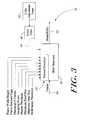
- FIG. 3is more detailed schematic depiction of the detection stage of FIG. 2, which includes a color matching stage in accord with the teachings of the present invention.
- FIG. 4Ais another detailed schematic block diagram depiction of the detection stage illustrating the erosion and dilation operations performed on the image according to the teachings of the present invention.
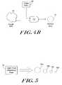
- FIG. 4Bis a schematic illustrative depiction of the manner in which color values stored in the color table are combined with a region of interest generated by the detection stage of FIG. 3 in accordance with the teachings of the present invention.
- FIG. 5is a schematic depiction of the scaling and low resolution eigenhead feature of the present invention.
- FIG. 6is a more detailed schematic block diagram depiction of the real time facial recognition system of FIG. 1 according to the teachings of the present invention.
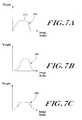
- FIGS. 7A through 7Cillustrate various embodiments of a center-weighted windowing functions employed by the facial recognition system according to the teachings of the present invention.
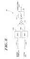
- FIG. 8is a block diagram depiction of the fast fourier transform stage for generating a correlation map.
- FIG. 9is a flow-chart diagram illustrating the generation of the eigenfaces by employing a dot product in accordance with the teachings of the present invention.
- FIGS. 10 and 10Aare flow-chart diagrams illustrating the acquisition and determination of a selected region of interest by the facial recognition system according to the teachings of the present invention.
- FIG. 11is a more detailed schematic block diagram depiction of the image manipulation stage of FIG. 1 in accordance with the teachings of the present invention.
- FIG. 12is a flow-chart diagram illustrating the discrimination performed by the real time facial recognition system of FIG. 1 according to the teachings of the present invention.
- the present inventionrelates to an image identification and verification system that can be used in a multitude of environments, including access control facilities, monitory transaction sites and other secured installations.
- the present inventionhas wide applicability to a number of different fields and installations, but for purposes of clarity will be discussed below in connection with an access control verification and identification system. The following use of this example is not to be construed in a limiting sense.
- FIG. 1illustrates a facial identification and verification system according to the teachings of the present invention.
- the illustrated systemincludes a multitude of serially connected stages. These stages include an image acquisition stage 22 , a frame grabber stage 26 , a head find stage 28 , an eye find stage 30 , and an image manipulation stage 34 . These stages function to acquire an image of an object, such as a person, and digitize it. The head and eyes are then located within the image.
- the image manipulation stage 34places the image in suitable condition for compression and subsequent comparison with pre-stored image identification information. Specifically, the output of the image manipulation stage 34 serves as the input to a compression stage 36 , which can be a principal component analysis compression stage.
- This stageproduces eigenvectors from a reference set of images projected into a multi-dimensional image space. The vectors are then used to characterize the acquired image.
- the compression stage 36in turn generates an output signal which serves as an input to a discrimination stage 38 , which determines whether the acquired image matches a pre-stored image.
- FIG. 2illustrates in further detail the front end portion of the system 20 .
- the image acquisition stage 22includes a video camera 40 , which produces an S-video output stream 42 at conventional frame rates.
- the video camera used hereinmay be a monochrome camera, a full color camera, or a camera that is sensitive to non-visible portions of the spectrum.
- the image acquisition stage 22may be realized as a variety of different types of video cameras and in general, any suitable mechanism for providing an image of a subject may be used as the image acquisition stage 22 .
- the image acquisition stage 22may, alternatively, be an interface to a storage device, such as a magnetic storage medium or other components for storing images or image data.
- image daterrefers to data such as luminance values, chrominance values, grey scale and other data associated with, defining or characterizing an image.
- the video output stream 42is received by a frame grabber 26 , which serves to latch frames of the S-video input stream and to convert the S-video analog signal into a digitized output signal, which is then processed by the remainder of the system 20 .
- a frame grabber 26serves to latch frames of the S-video input stream and to convert the S-video analog signal into a digitized output signal, which is then processed by the remainder of the system 20 .
- conventional video camerasproduce an analog video output stream of 30 frames per second, and thus the frame grabber 26 is conventionally configured to capture and digitize image frames as this video rate.
- the video cameraneed not be limited to S-video, and can include near IR or IR mode, which utilizes RS 170 video.
- the frame grabber 26produces a digitized frame output signal 44 which is operatively communicated with multiple locations. As illustrated, the output signal 44 communicates with a broadly termed detection stage 50 , which corresponds at least in part to the head find stage 28 of FIG. 1 . The output signal 44 also communicates with the compression stage 36 , which is described in further detail below. Those of ordinary skill will realize that the camera itself can digitize acquired images, and hence the frame grabber stage 26 can be integrated directly into the camera.
- FIG. 3is a further schematic depiction of the detection stage 50 of FIG. 2 .
- the video frame signal 44is received by the detection stage 50 .
- the signalcomprises an N by N array of pixels, such as a 256 ⁇ 256 pixel array, which have selected chrominance and luminance values.
- the pixelsare inputted into the detection stage 50 , and preferably are analyzed first by the motion detection stage 54 .
- the motion detection stage 54receives a number of input signals, as illustrated, such as signals corresponding to frame width and height, frame bit counts and type, maximum number of frames, selected sampling pixel rate, motion threshold values, maximum and minimum head size, and RGB index threshold values.
- One or more of these additional input signals in combination with the frame input signal 44trigger the motion detection stage to assess whether motion has occurred within the field of view.
- the motion detection stage 54is adapted to detect subtle changes in pixel values, such as luminance values, which represent motion, especially when an object moves against a relatively still background image (such as a kiosk, cubicle or hallway).
- One method of determining motionis to perform a differencing function on selected pixels in successive frames, and then comparing changes in pixel values against a threshold value. If the pixel variations within the field of view exceed the threshold value, then an object is deemed to have moved within the image. Conversely, if the changes are below the threshold, the system determines that no suitable motion has occurred.
- a spatio-temperal filtering schemecan be applied to the captured image to detect motion, as set forth in U.S. Pat. No. 5,164,992 of Turk et al., the contents of which are hereby incorporated by reference.
- a sequence of image frames from the camera 40pass through a spatio-temperal filtering module which accentuates image locations which change with time.
- the spatio-temperal filtering moduleidentifies within the frame the locations and motion by performing a differencing operation on successive frames of the sequence of image frames.
- a typical output of a conventional spatio-temperal filter modulehave the moving object represented by pixel values having significantly higher luminance than areas of non-motion, which can appear as black.
- the spatio-temperal filtered imagethen passes through a thresholding module which produces a binary motion image identifying the locations of the image for which the motion exceeds a threshold.
- the thresholdcan be adjusted to select a certain degree of motion. Specifically, minor movements within the field of view can be compensated for by requiring heightened degrees of motion within the field of view in order to trigger the system.
- the thresholding modulecan be adjusted to locate the areas of the image containing the most motion. This filtering scheme is particularly advantageous in monitoring transaction environments where an individual seeking access to, for example, an ATM machine, would have to approach the ATM machine, and thus create motion within the field of view.
- the blob detection stage 56analyzes the binary motion image generated by the motion detection stage 54 to determine whether motion occurs within the field of view, for example, by sensing a change in pixel content over time. From this information, the blob detection stage 56 defines a region of interest (ROI) roughly corresponding to the head position of the person in the field of view. This ROI is truly a rough approximation of the region corresponding to the head and practically is an area larger than the head of the person, although it may also be a region of about the same size.
- ROIregion of interest
- the blob detection stageemploys known techniques to define and then correlate an object (e.g., the head of a person) in the image.
- the present inventionrealizes that the motion information can be employed to roughly estimate the region of interest within the image that corresponds to the person's head.
- the blob detection stage 56designates a “blob” corresponding roughly to the head or ROI of the person within the field of view.
- a blobis defined as a contiguous area of pixels having the same uniform property, such as grey scale, luminance, chrominance, and so forth. Hence, the human body can be modeled using a connected set of blobs.
- Each blobhas a spatial and color Gaussian distribution, and can have associated therewith a support map, which indicates which pixels are members of a particular blob.
- the ability to define blobs through hardwareis well known in the art, although the blob detection stage 56 can also be implemented in software.
- the systemtherefore clusters or blobs together pixels to create adjacent blobs, one of which corresponds to a person's head, and hence is defined as the ROI.
- the color table 60can be employed to further refine the ROI corresponding to the head.
- the word “refine”is intended to mean the enhancement, increase or improvement in the clarity, definition and stability of the region of interest, as well as a further refinement in the area defined as the region corresponding to the person's head.
- the ROI established by the motion detection stageis a rough region, larger than the head, that defines a general area within which the head can be found.
- Flesh tone colorscan be employed to “lighten” or reduce the ROI characterizing the person's head to better approximate the area corresponding to the head. This process serves to overall refine the region of interest.
- the color tableis intended to be representative of any suitable data storage medium that is accessible by the system in a known manner, such as RAM, ROM, EPROM, EEPROM, and the like, and is preferably a look-up table (LUT) that stores values associated with flesh tone colors of a sample group.
- RAMrandom access memory
- ROMread-only memory
- EPROMerasable programmable read-only memory
- EEPROMelectrically erasable programmable read-only memory
- LUTlook-up table
- the present inventionrealizes that people of different races have similar flesh tones. These flesh tones when analyzed in a three-dimensional color or RGB space are similarly distributed therein and hence lie essentially along a similar vector. It is this realization that enables the system to store flesh tone colors in a manner that allows for the rapid retrieval of color information.
- the flesh tone color valuesare created by sampling a reference set of people, e.g., 12-20 people, and then creating a histogram or spatial distribution representative of each of the three primary colors that constitute flesh tone, e.g., red, blue and green, using the reference set of people as a basis in ST color space (H f ). Alternatively, separate histograms for each color can be created.
- the color histogramis obtained by first reducing the 24 bit color to 18 bit color, generating the color histogram, and then transforming or converting it into ST color space from the intensity profile in the RGB space. The system then obtains the non-face color histogram in ST color space (H n ). This is obtained by assuming that non-face color is also uniformly distributed in the RGB space. The histogram is then converted into ST color space.
- the transformation into ST color spaceis performed according to the following two equations:
- the color histogramsare then normalized by converting H f and H n to P f and P n according to Bayes Rule, which determines the face probability within the color space. Consequently, the normalized face can be represented as:
- the systemthen calculates the width and height of the table, as well as the values of the face probability look-up table 60 according to the following formula:
- a certain portion of the resultant histogram(s)is then defined, for example, about 90% of the histogram or class width, for each of the colors in the histogram. This defines upper and lower limits of color values that are deemed acceptable by the system when determining whether the input pixel values of the frame 44 are representative of flesh tone.
- These histogram color distributionsare then stored in the color table 60 .
- the system 20further includes a color adjustment stage 62 that is employed to change or to adjust the flesh tone color values stored within the table. For example, if additional people are sampled, these color distribution values can be combined with the histogram values stored in the table.
- the color table values 64are introduced to a color reduction stage which reduces the color from 24 bit to 16 bit for ease of handling. This can be performed using known techniques.
- the detection stage 50then further defines the ROI. The detection stage 50 ignores darker colors by setting to zero any pixel having a value less than 16.
- the systemalso includes a threshold stage 84 that compares the rough ROI with a threshold value to convert it to a binary image.
- An erosion stage 86performs an erosion operation on the binary image to remove noise and disconnect hair pixels from face pixels. The erosion operation reduces the size of an object by eliminating area around the object edges, and eliminates foreground image details smaller than a structuring element. This increases the spacing between the face and the hair in the image.
- a ⁇ B⁇ b ⁇ B ⁇ ( A ) - b ⁇ ⁇ if ⁇ ⁇ b : ( x , y ) ⁇ ⁇ then ⁇ - b ⁇ ( - x , - y ) ( Eq . ⁇ 5 )
- erosionis the intersection of all translations, where a translation is the subtraction of a structuring element set member from an object set member.
- the symbolis used to signify the erosion of one set by another.
- Ais the set representing the image (ROI)
- Bis the set representing the structuring element
- bis a member of the structuring element set B.
- the symbol (A) -bdenotes the translation of A by ⁇ b.
- a dilation stage 88performs a dilation operation thereon to obtain the face regions within the ROI.
- the dilation operationis employed to expand or thicken the ROI, and is thus the inverse operation of erosion.
- the symbol ⁇signifies the erosion of one set by another.
- Ais the set representing the image
- Bis the set representing the structuring element
- bis a member of the structuring element set B.
- the term (A) brepresents the translation of A by b.
- the set Bcan be defined as including the following coordinates ⁇ (0, 0), (0, 1), (1, 0), (1, 1) ⁇ .
- the output of the dilation stageis the ROI.
- the systemcan further process the image data by defining the largest area as the dominant face region, and merge other smaller face regions into the dominant face region.
- the center of the ROIis then determined by placing a 128 ⁇ 128 pixel box on the ROI (e.g., face) by setting its center as:
- the foregoing detection stage 50hence compares the rough ROI with the contents of the color table 60 , performs selected erosion and dilation operations to obtain the pixels associated with the face (by analyzing chrominance values), and ultimately refines the ROI based on the contents of the color table 60 .
- the entire operationis illustratively shown as a logic operation in FIG. 4 B.
- the detection stage 50inputs data associated with the blob or rough head ROI 66 generated by the blob detection stage 56 to one input terminal of an AND gate 70 .
- the color table 60is coupled by communication pathway 64 to the other input of the AND gate 70 .
- the illustrated gate 70performs a logic operation on the inputs and generates an output image that corresponds to the overlap of identical data values at the input.
- This operationserves to refine the rough ROI.
- the rough ROIis tightened or made smaller than, or maintained approximately the same size as the rough ROI, since the flesh tone colors that exist in the ROI and which match the stored color values in the table 60 are retained, while colors in the ROI that are not stored in the table 70 are discarded.
- the ROIis processed to produce a refined ROI 74 that more closely resembles the person's head.
- a significant advantage of employing the motion detection stage 54 and the color table 60 in defining the ROI corresponding to the headis that these features can be performed in real-time, since there is generally no processing and hence time cost associated with employing the motion detection and color features of the detection stage 50 .
- the motion detection stage 54determines motion within the field of view prior to the system actually needing to utilize the acquired image information. For example, a person initially entering the field of view in a secured area generally does not require immediate access to the secured facility.
- the system 50detects motion, blobs together pixels that roughly correspond to the person's head, and then refines this ROI using pre-stored flesh tone colors according to the above techniques. This is performed in real-time, with minimal processing cost and inconvenience to the person.
- refining the ROIallows the system to more quickly and accurately locate an object, such as the eyes, within the ROI, since the ROI has been closely tailored to the actual size of the hand of the person.
- the detection stage 50can also define the head ROI when the system first detects motion followed by subsequent frames where no motion is detected, that is, when the object or person within the field of view is immobile, or the acquired image data is static. This may occur when a person originally enters the field of view and then immediately stops moving.
- the illustrated detection stage 50includes an eigenhead generation stage 76 that generates eigenvectors that correspond to a head using PCA theory and techniques. Specifically, the eigenhead stage 76 initially samples a reference set of individuals and performs a PCA operation thereupon to generate a series of eigenheads that define the distribution of heads within a multi-dimensional image space.
- the eigenheads employed by the present inventionare preferably low resolution eigenheads, such as between about 17 ⁇ 17 pixel and about 64 ⁇ 64 pixel resolution, and preferably about 21 ⁇ 21 pixel resolution, since a rough size match rather than intricate feature matching is all that is required to quickly define the ROI.
- An advantage of employing low resolution eigenheadsis that they are relatively fast to process.
- the eigenheads generated by the eigenhead stage 76are further scaled to various sizes, illustrated as head sizes 78 A- 78 D, to enable a complete and accurate correlation match.
- the ROIis searched using an eigenhead (e.g., with eigenhead 78 A) of a particular size as a windowing function, and the system determines if there is a sufficiently high correlation match. If no match is found, then the eigenhead is scaled downward, for example, to eigenhead size 78 B, and again the motion ROI is searched with this eigenhead template. This process is repeated until a match is found. If none is found, then the eigenhead templates are scaled upwards in size.
- the detection stage 50employs a multi-scale correlation technique to identify a ROI corresponding to a person's head by searching the ROI with a variable-sized eigenhead template to determine if there is a correlation match.
- FIG. 6is a more detailed schematic representation of the primary eye find stage 30 of FIG. 1 .
- the output of the detection stage 50is a series or list of ROIs corresponding to a person's head (head ROI).
- the ROIis passed through a head center and scaling stage 110 that centers and scales the ROI for subsequent use.
- the center and scaling stage 110determines the coordinates of the center of the region of interest.
- the head center coordinatescan be determined by calculating the mean value of the contours of the ROI.
- the size of the head ROIis estimated as the mean distance from the head center to the contour edges of the ROI. This information is useful for determining the approximate location of the eyes within the ROI, since the eyes are generally located within a rough geometrical area of the overall head ROI.
- the output signal 112 generated by the center and scaling stageis communicated to a first eye find stage 120 which comprises part of the overall identification system 20 and specifically the primary eye find stage 30 .
- the first eye find stage 120is adapted to receive a number of input signals carrying a variety of different image data or information.
- the frame data signal 44 generated by the frame grabber 26is received by the first eye find stage 120 .
- an nieye template module 130generates and stores a number of eigenfeature or nieye templates corresponding to a reference set of images.
- the eigeneye templatescan be constructed in known fashion, the general construction of which is described in further detail below.
- the eigen template modulegenerates an output signal that is also received by the first eye find stage 120 .
- the centre-weighted windowing functionthat weights image data more strongly in the middle portion of the image while conversely weighting data less strongly towards the outer regions of the image.
- FIGS. 7A through 7Cillustrate exemplary weighting profiles 202 , 206 , 208 employed by the eye find stage 30 of the invention.
- FIG. 7Agraphically illustrates one such weighting profile, and defines image data width along the abscissa, and normalized data weight along the ordinate.
- the illustrated weighting profile 200has a sinusoidal-shape and is employed by the present invention as a window function.
- the functionweights image data in a central region 202 of the window more strongly than image data at the edges of the image. Hence, the system accords the most weight to image data that has the highest percentage chance of being incorporated into the eigen template during production of the same. Conversely, the weighting profile accords less significance, and preferably little or no significance, to image data located at the boundary regions of the image.
- This center-weighting window functionensures that the system maximizes the incorporation of essential image data into the correlation, while consistently minimizing the chance that unwanted extraneous information is employed by the system.
- the system 20places the window function over a selected portion of the ROI, and then analyzes the ROI using this window function.
- the window function shapethus defines that selected portion of the image to be analyzed by the system of the invention.
- the illustrated sinusoidal-shape of the window function 200thus weights more heavily data corresponding to the portion of the ROI that overlaps with the center portion of the function relative to the outer boundaries of the function.
- the use of a center-weighted window functionenables the system 20 to avoid incorporating unwanted image data into the eigen template.
- the image datamay be accidentally corrupted when employing conventional window functions by including unwanted data associated with adjacent facial features, shading, and other illumination perturbations.
- the systemavoids incorporating this unwanted data into the eigentemplates, thereby minimizing the likelihood of the system generating false matches.
- eigenfacescan be created from a reference set of images in accord with PCA principles described in greater detail below.
- One or more features of the acquired facial imagescan be utilized to form selected eigentemplates of a particular facial feature.
- eigenvectors corresponding to eyesand thus called nieyes, can be created from the reference images forming part of the reference set. Variations among eyes are prevalent in the reference set of images because of the various people that constitute the reference set. Additional factors, however, influence the random variations of the reference images.
- the systemmay inadvertently include data associated with the eyeglass frame and other glassware components when generating the eigenface.
- the eye portion of the imagemay include information corresponding to the eyeglass frame.
- this additional informationcorrupts the overall acquired image data, and when projected onto the image space, may actually distort the spatial location of the eye within this image space.
- the eyemay be spatially shifted right or left, thus destroying the true spacing between eyes as well as the particular orientation of the eye relative to other facial features. Since this information is utilized by the system to generate templates, which themselves are employed to identify matches with a newly acquired image, the system could be prone to false matches.
- FIGS. 7B and 7Cillustrate yet other examples of weighting profile shapes that can also be employed by the eye find stage 30 of the present invention.
- FIG. 7Billustrates a bell-curve type weighting profile 206 that also accords stronger weight to a middle portion of the image as opposed to the peripheral or boundary regions.
- the step function 208further accords, in a stepwise fashion, more weight to image located within the interior regions of the image as opposed to the outer regions.
- An advantage of employing the eigeneye templates in the eye find stage 120is that PCA projections in image sub-space require little or no processing time, and thus are simple and efficient to use in facial reconstruction systems. Since the Eigenface method is based on linearly projecting an image onto multi-dimension image space, this method yields projection directions that maximize the total scatter across all the facial images of the reference set. The projections thus retain unwanted variations due to lighting and facial expression. This scatter can be greater than the conventional scatter that is produced in the projections due to variations in face identity.
- One method to overcome this scatteris to include in the reference set a number of different images that mimic the continuum of lighting conditions in order to more evenly distribute points in the image space. These additional images, however, could be costly to obtain and require significant intrusions on the reference people.
- One technique to address the scatter in the eigenimagesis to correct for the variations in lighting and expression during the image manipulation stage 34 or during any other convenient stage of the illustrated facial recognition system 20 .
- a correlation in the Eigen approachis a nearest neighbor classifier scheme in image space.
- a new imagee.g., the ROI
- This correlationcan be performed using the traditional Eigen approach, or can be performed by calculating the eigen coefficients using a fast fourier transform (FFT) approach to generate a correlation map.
- FFTfast fourier transform
- the system 20employs the FFT approaching the eye find stage 20 , and specifically to any selected input to the head find stage 28 or the eye find stage 158 to perform the correlation between the newly acquired image and one or more reference images.
- the input imageis initially acquired and digitized, and then processed by the detection stage 50 .
- the imagee.g., frame data and/or nieyes
- the imageis reduced to a digital representation of pixel values.
- These pixel valuescorrespond to the measure of the light intensity throughout the image.
- an imagemay be digitized to form a rectangular or square array of pixel values which are indicative of the light intensity within the image.
- a facial imagecan be reduced to N rows by M columns of pixel data resulting in an aggregate of N ⁇ M pixel values. Each of these pixel values can be identified as to location by row and column.
- ROIdistinctive object
- a security applicationit may be necessary to identify an individual's face from a larger reference set of faces of individuals authorized to access a secured location. Conventionally, this has been accomplished by storing a digital representation of the face of each authorized individual in a vector or matrix representation. The digitized facial image of the person requesting access to the secured resource is then matched against the set of reference faces authorized for access to the resource in order to determine if there is a match.
- the matching processhas conventionally been performed by a mathematical correlation of the digital pixel values representing the face of the individual requesting access with the pixel values of the faces from the reference set.
- I(x i , y j )is the luminescence value for the facial image to be detected at each of the pixel values
- I R (x i , y j )is the corresponding facial image from the reference set.
- the correlationis performed for each image from the reference set. It is well known that a good match of digital data is represented by a large correlation value, and thus the reference image with the greatest correlation is considered the best match to the image to be detected.
- a predetermined thresholding valueis set so as to ensure that the match is sufficiently close. If all the calculated coefficient values are below the threshold value, it is presumed that the detected face or feature is not found in the matching reference set.
- the objects or feature to be identifiedmay comprise only a subset of the larger image
- the images from the reference setmust be correlated over all possible subsets of the image in order to detect the object or feature within the larger image.
- the face to be identified or detectedmay exist within a background of unrelated objects, and also positioned at almost any location within the larger image.
- the reference facesare correlated with all possible subsets of the image to find and to identify the face to be matched.
- the methods and techniques of the current inventionare advantageously employed using the concept of an eigenface basis to reduce this computational requirement.
- the face to be detected from a training or reference set of facial imagescan be defined by a mathematical relationship expressed as I(x i ,y i ).
- the training or reference set of acquired face imagesbe represented by ⁇ 1 , ⁇ 2 , ⁇ 3 , . . . ⁇ M .
- the average face of this reference setis defined by
- the meanis found by adding all the faces together in the reference set and then dividing by the number of face images. The mean is then subtracted from all the face images. A matrix is subsequently formed from the resultant mean adjusted faces.
- PCAprincipal component analysis
- the contrast and brightness of each of the images in the reference set ⁇ i ⁇may differ significantly from each other and from the image to be matched. These differences may skew the matching results, and thus create errors in detection.
- the present inventioncompensates for these differences. Specifically, the image to be matched is adjusted relative to each image from the reference set before correlation is performed. The statistical mean and standard deviation of all the pixel values for the individual reference image are determined, and the pixel value of the image to be matched are adjusted according to the following rule:
- a windowing functionis defined that weights the product of the corresponding luminescence values according to their significance in detecting the object within an image. For example, if one were attempting to find an eye within a facial image, a windowing function can be defined to emphasize the correlation of certain aspects of the reference eye and to avoid the confusion associated with peripheral features such as eyeglasses.
- the windowing functionhas a shape corresponding to the previously-described center-weighted windowing function that accords greater weight or significance to pixel values in the center of the windowing map and lesser or no significance to those on the edges of the map, as shown in FIGS. 7A, 7 B and 7 C.
- This windowing mapmay be employed with a two dimensional circular geometry. Pixel values outside the bounds of the windowing map have a weight of zero, and thus do not enter into the correlation calculation.
- I( x )be the image to be analyzed, where I( x ) is moved under the window function to analyze it.
- the effect of brightness and contrast variations in the part of the image under the windowis to be minimized by scaling I( x ) by a factor c, the standard deviation of the pixel values in the reference image undergoing analysis, and an additive constant b which is the mean of the pixel values in that reference image.
- cI( x )+bwhich is expressed as I s (x).
- the function p(x,y)can be described in terms of its coefficients with respect to a set of eigen basis functions ⁇ k (x). These coefficients, which are designated as ⁇ k (y), are defined as the inner products.
- the foregoing vectorcan then be used in a standard pattern recognition algorithm to determine which of the faces from the reference set, if any, best matches the unknown face.
- FIG. 8is a schematic block diagram depiction of the eye find stage 120 which can employ, among other things, the Discrete Fast Fourier Transform (DFFT) approach described above.
- the eye find stage 120can employ DFFT procedures to correlate the ROI with the eigen template, such as the nieye templates, to produce a correlation map.
- the expressions for the correlationmay be calculated in a more efficient fashion using an DFFT approach.
- the expressionsmay be computed by transforming the calculation to the frequency domain, and then performing an inverse transform operation to obtain the result in the spatial domain. It has been realized that the sum of products in the space domain is equivalent to the product of the DFFT in the frequency domain. An inverse DFFT transform of this product then produces the required result.
- the inherent efficiency of the DFFTcan be utilized to significantly reduce the overall number of calculations required to obtain the results.
- the eye find stage 120receives a template 112 A from the Amsterdamye template stage 130 .
- the eye find stage 120employs one or more transform stages 210 A and 210 B to convert the eigen templates and the ROI signal 112 into the frequency domain to reduce the amount of computations necessary to produce the correlation map 214 .
- the DFFT stages 210 A, 210 Breduce the amount of computations since rather than constructing a map by summing the products of the templates and the ROI, the eye find stage 120 of the invention merely acquires the dot product, in the frequency domain, of the input signals by transforming the image and template into the frequency domain.
- the converted datais then multiplied by the multiplier 213 to perform the foregoing dot product.
- the eye find stage 120then reconverts the data into the spatial domain be employing the inverse transform stage 212 .
- the stage 120hence generates a correlation map identical to that generated employing the conventional spatial technique, without manipulating large, complex equations.
- the systemis faster, more responsive to input image data, and is capable of generating correlation maps in real-time.
- FIG. 9is a schematic flowchart diagram illustrating the operations employed to identify an individual face within a larger image.
- the systemfirst generates a digitized image consisting of a face that is to be matched to a particular face in a reference set of stored faces, as set forth in steps 305 and 310 .
- Each face within the reference set of facesis then normalized and converted into the frequency domain using the DFFT 210 A, and a set of basis vectors (e.g., eigenfaces or Amsterdam), ⁇ k , that span the set of known reference faces is obtained employing conventional Eigen techniques. This is set forth in steps 315 and 320 .
- basis vectorse.g., eigenfaces or Amsterdam
- the systemthen obtains the component coefficients ⁇ k in terms of the basis vectors ⁇ k for each face within the reference set of faces by employing a dot product operation.
- Thiscan be performed in the eye find stage 120 .
- the stage 120receives the centered and scaled ROI and an eigen eye template from the template stage 130 .
- the eye find stagecan employ a program or hardwired system that converts the nieye data into vector coefficients in the frequency domain.
- the systemthen normalizes the unknown facial image, as set forth in step 330 , for contrast and brightness for each reference image, and converts the normalized image data into the frequency domain using DFFT 210 B.
- the systemdefines a windowing function of the type described above (e.g., center-weighted function) to emphasize selected local features or portions of the image. This is set forth in step 335 .
- the systemthen overlays the image on the windowing function, and calculates a set of component coefficients ⁇ for the unknown image in terms of the eigenfaces ⁇ k using a dot product operation, step 340 .
- the systemcompares the component coefficients ⁇ of each face from the reference set with the coefficients of the unknown image to determine if a match exists.
- the illustrated system 20thus provides an integrated real-time method of detecting an individual face within an image from a known reference set of faces by converting the template and ROI data into the frequency domain, obtaining the dot product, and then reconverting the data into the spatial domain to develop a correlation map.
- a face detection applicationthe advantages and benefits of the invention are not limited to this application.
- the inventioncan be used to advantage in any application with the need to identify or detect an object or feature within a digitized image, such as a head or eyes of an individual.
- a known data structure or pattern of digital data from a reference set of such data structurescan be identified within a larger set of digitized values.
- the systemcan also input data associated with eye clusters generated by the eye cluster stage 140 .
- the Eye cluster stage 140logically organizes a reference set of eye images into clusters in order to develop templates that used by the eye find stage 120 to locate the eyes. Specifically, as described above, the eye find stage 120 compares the centered ROI with the eye cluster template to determine the existence of a match.
- eye clustersand in accordance with the teachings of the present invention, how they are implemented by the present system to locate a region in the ROI.
- the eye find stage 120receives the original image frame data 44 and the ROI that has been scaled and centered by the scaling stage 110 , and performs a correlation match with the eigen eye templates and windowing function to determine the eye locations within the image. As set forth above, this correlation can be performed in the spatial or frequency domain. If the eye find stage 120 produces a sufficiently high correlation, and thus locates the eyes within the image, the stage generates an output signal 122 that is indicative of eye locations, and which is received by the compression stage 36 .
- the system 20reverts to a backup technique that employs the second head find stage 146 and the second or back-up eye find stage 156 .
- the first eye find stage 120generates an output signal 121 that serves to actuate the frame grabber 26 to re-acquire an image, while concomitantly generating an input signal for the head find stage 146 .
- the second head find stage 146receives the original frame data 44 , the eye find stage output signal 121 , as well as eigenhead templates stored in the eigenhead template stage 150 .
- the eigenhead templatesare generally low resolution eigenheads produced by the foregoing Eigen technique.
- the second head find stage 146performs a correlation match employing the eigenhead templates stored in the eigenhead stage 150 , and which correspond to the previously captured region of interest. Assuming there is a match at this stage, the system 30 produces an output signal which actuates a second eye find stage 156 , which receives signals similar to the first eye find stage 120 , to again attempt to locate the eyes.
- the systemfails the second time to determine the eye locations, the system produces an output signal 158 which actuates the frame grabber 26 to reacquire an image.
- the redundant head and eye find stages 146 and 156increase the eye location accuracy of the system.
- the illustrated system 20attempts to balance these competing concerns by opting for the fast, real-time initial approach of locating the eyes with the first eye-find stage 120 . If this fails, however, the system employs the head find and eye find stages 146 and 156 in order to improve the overall accuracy of the system.
- the operation of the primary eye find stage 30 of FIGS. 1 and 6is further illustrated in the flow chart schematic diagrams of FIGS. 10 and 10A.
- the head ROIs produced by the detection stage 50 of FIG. 3serve as the input to the primary eye find stage 30 of FIG. 6 .
- the systemdetermines if the number of ROIs within the image are greater than zero. This is determined in step 220 . If the number is greater than zero, the system sets a motion ROI counter to zero, as set forth in step 224 , and then proceeds to further process the ROI. Conversely, if the system determines that the number of head ROIs is not greater than zero, then the system determines whether the last ROI is devoid of appropriate image data, as set forth in step 222 . If the image is devoid of image data, then the system actuates the image acquisition device 22 and frame grabber 26 to reacquire an image. If not, then the system proceeds to step 226 , as set forth below.
- the system 20determines that the last motion ROI contains data by setting the motion ROI counter to zero, the system calculates the head center within the image, as set forth in step 226 . The system then proceeds to calculate the appropriate eye scale step 228 , and then locates the eyes in the region of interest ROI, step 230 . As set forth in step 232 , if the system determines that the eyes in the ROI were located, then an eye error counter and the last motion ROI counter are set to zero, thus signifying that an accurate eye location operation has occurred. This is set forth in step 234 . The system then passes the eye location image information onto the compression stage 36 .
- the systemincrements the eye error counter to signify that an error has occurred while attempting to identify or locate the eyes within the head ROI.
- the system 20then reverts to a backup head find stage 146 and second eye find stage 156 to locate the eyes.
- the systemonce again locates the head in the region of interest, as set forth in step 246 .
- This particular stepis in feedback communication with two particular feedback loops 242 and 245 .
- the systemcalculates the spatial Cartesian coordinates of the ROI, as set forth in step 242 . This step occurs after the motion counter has been set to zero in step 224 .
- the systemcalculates the head center coordinates, step 244 , and which occurs after step 226 .
- the systemlocates the head for the second time in the ROI, as set forth in step 246 , the system then attempts to locate the eyes. If the eyes are located this time, the system 20 proceeds to set the eye error counter and the last ROI counter to zero, as set forth in step 252 (similar to step 234 ). The eye location information is then transferred to the compression stage 36 .
- the error counteris once again incremented, as set forth in step 260 , to signify that an additional eye location failure has occurred.
- the systemthen proceeds to set the last ROI in the list to a value equal to the last motion ROI, as set forth in step 262 . Once the counter is set to a value corresponding to the last ROI, the system resets itself to accommodate additional ROI information generated by the detection stage 50 . The system then repeats the entire process.
- the eye location image data 122is then transferred to the compression stage 36 .
- the eye location informationcan initially pass through a rotation stage 124 which seeks to rotate the image information to a selected orientation to enable an accurate and appropriate comparison with prestored images.
- the rotated image datais then scaled by the scaling stage 126 to an appropriate size, and then normalized by the normalization stage 128 to attain a normalized image suitable for processing by the compression stage.
- Image data information not associated with the eyesis then masked, or removed, by the masking stage 132 .
- the rotation stage 124 , scaling stage 126 , normalization stage 128 , and masking stage 132all employ conventional processes that are readily apparent to one of ordinary skill in the art.
- the eye location informationis then transferred to a compression stage 36 where an Eigen procedure is performed on the data.
- This procedureis performed, in one embodiment, by first obtaining a training reference set of faces by acquiring a number of reference images.
- the training or reference setis normalized, as described above, so that all faces are the same scale, position, orientation, mean, and variance.
- the actual encoding or compression processcan employ a Karhunen-Loeve transformation or an eigenvector projection technique, which encodes an image of a person's face or other facial feature, such as nose, eyes, lips, and so forth, as a weighted set of eigenvectors. This eigenvector projection technique is described more fully in U.S. Pat. No.
- an image of a faceis projected onto a face space defined by a set of reference eigenvectors.
- the reference set of eigenvectors, or eigenfacescan be thought of as a set of features which together characterize the variation between face images within a reference set of facial images.
- This distribution of faces in the reference set of facescan be characterized by using principal component analysis to extract face information that characterizes the variations or differences between a newly acquired image (the projected image) and the eigenfaces.
- Principal component analysisis a known technique.
- the resulting eigenvectors produced by performing the PCAdefine the variation between the face images within the reference set of faces, and can be referred to as eigenfaces.
- an eigenfaceis formed by multiplying each face in the training set by the corresponding coefficient in the eigenvector.
- an image signalcan be represented as a function of these eigenfaces by projecting the image signal into the space defined by these eigenfaces.
- each face image I(x,y)is a two-dimensional image having an N by N array of intensity values (8-bit).
- the face imagecan be represented in a multi-dimensional image space as a vector (or point) of dimension N 2 .
- a typical acquired image of, for example, 256 by 256 pixelsbecomes a vector within this multi-dimensional space of 65,536, or equivalently, a point in a 65,536-dimensional image space.
- a series of acquired imagescan thus be mapped to a series of points within this rather vast image space.
- each vector having a length N 2describes an N by N image, and can be represented by a linear combination or concatenation of vector values of the original face images that constitute the reference set of images.
- the matrix Cis N 2 by N 2 , and determining the N 2 eigenvectors and eigenvalues can become an intractable task for typical image sizes. Consequently, if the number of data points in the face space is less than the dimension of the overall image space, namely, if M ⁇ N 2 , there are only M ⁇ 1, rather than N 2 , meaningful eigenvectors. Those of ordinary skill will recognize that the remaining eigenvectors have associated eigenvalues of zero.
- the foregoing analysisgreatly reduces the calculations necessary to handle the image data, from the order of the number of pixels in the images (N 2 ) to the order of the number of images in the training set (M).
- the training set of face imagescan be relatively small (M ⁇ N 2 ), although larger sets are also useful, and the calculations become quite manageable.
- the associated eigenvaluesprovide a basis for ranking or ordering the eigenvectors according to their usefulness in characterizing the variation among the images, or as a function of their similarity to an acquired image.
- the eigenvectors embody the maximum variance between images and successive eigenvectorshave monotonically decreasing variance.
- the eigenfacesspan an M′-dimensional subspace of the original N 2 image space.
- the M′ most significant eigenvectors of the L matrixare selected as those with the largest associated eigenvalues, and therefore contain the most useful image information, e.g., contain maximum variance information.
- a newly acquired faceis represented by a weighted series of eigenvectors formed from the most significant eigenvectors of the image sub-space. It is important to note that this recognition technique assumes that the image, which is not part of the original reference set of images, is sufficiently “similar” to those in the training set to enable it to be well represented by the eigenfaces. Hence, a new face image ( ⁇ ) is transformed into its eigenface components (i.e., projected into the face space) by a simple operation, namely,
- the Eigen head template stage 164can include a database of the eigenfaces created by the foregoing Eigen approach. This information can be received by the compression stage 36 or by the discrimination stage 38 .
- the compression stage 36preferably communicates with the database of eigenfaces stored in the eigenhead template stage 164 .
- the eye information 122 outputted by the first eye find stage 120is projected by the compression stage 36 into eigenspace and a new set of coefficients is generated that correspond to a weighted sum of the eigen templates stored in the stage 164 .
- the discrimination stage 38compares the coefficients corresponding to the new image with a pre-stored coefficient value, or threshold, to determine if a match occurs.
- a pre-stored coefficient valueor threshold
- the foregoing vector ⁇is used in a standard pattern recognition algorithm to find which of a number of pre-defined facial feature classes, if any, best describes the newly acquired image.
- the simplest method for determining which face class provides the best description of an input face imageis to find the face class k that minimizes the Euclidean distance
- ⁇ ⁇is a vector describing the kth face class.
- the face classes ⁇ iare calculated by averaging the results of the eigenface representation over a small number of face images (as few as one) of each individual. A face is classified as belonging to class k when the minimum ⁇ ⁇ is below some chosen threshold ⁇ ⁇ .
- the faceis classified as “unknown”, and optionally used to create a new face class or the system can deny the person access to the secured facility.
- the Euclidean distanceis thus employed to compare two facial image representations to determine an appropriate match, e.g., whether the face belongs to a selected face class of pre-stored images.
- an appropriate matche.g., whether the face belongs to a selected face class of pre-stored images.
- the recognition of the newly acquired facecan be verified by performing a simple threshold analysis, that is, if the Euclidean distance is below some pre-determined threshold then there is a match, and the person, for example, can gain access to a secured facility.
- ⁇ 2⁇ ( ⁇ f ) ⁇ 2 ,
- Case 1In the first case, an individual is recognized and identified. In the second case, an unknown individual is present. The last two cases indicate that the image is not a face image. Case three typically shows up as a false positive in most other recognition systems. In the described embodiment, however, the false recognition may be detected because of the significant distance between the image and the subspace of expected face images.
- the eigenfaces approach to face recognitioninvolves the steps of (1) collecting a set of characteristic face images of known individuals; (2) calculating the matrix L, (3) finding the corresponding eigenvectors and eigenvalues, (4) selecting the M′ eigenvectors with the highest associated eigenvalues; (5) combining the normalized training set of images according to Eq. 7 to produce the reduced set of eigenfaces ⁇ ⁇ ; (6) for each known individual, calculate the class vector ⁇ ⁇ by averaging the eigenface pattern vectors ⁇ calculated from the original images of the individual; (7) selecting a threshold ⁇ ⁇ which defines the maximum allowable distance from any face class; and (8) thresholding ⁇ 1 which defines the maximum allowable distance from face space.
- each new face to be identifiedcalculate its pattern vector ⁇ , the distances ⁇ i to each known class, and the distance ⁇ to face space. If the distance ⁇ > ⁇ 1 , classify the input image as not a face. If the minimum distance ⁇ ⁇ ⁇ ⁇ and the distance ⁇ 1 , classify the input face as the individual associated with class vector ⁇ ⁇ . If the minimum distance ⁇ ⁇ > ⁇ ⁇ and ⁇ 1 , then the image may be classified as “unknown”, and optionally used to begin a new face class.
- FIG. 12is a schematic flow-chart illustration of the discrimination or thresholding which occurs when the system 20 attempts to determine whether a match has occurred.
- the systemstores the eigen coefficients in a selected memory location, such as the eigen template stage 164 .
- the compression stage 36calculates or determines the new coefficients corresponding to the newly acquired image or ROI
- the system 20searches the eigen database for a match, step 410 .
- the systemdetermines whether the newly acquired face/facial feature is in the database, as set forth in step 415 . This searching and matching is performed by comparing the eigenvalues of the new face with a threshold value.
- the systemsignifies a match, and the person is allowed access, for example, to a secured facility, step 420 . If no match occurs, then the system reacquires an image and performs the steps and operations described above in connection with system 20 , as set forth in step 425 .
- the foregoing systemperforms a number of operations, either singularly or in combination, that enables the acquisition, comparison and determination of a facial match in real-time, with minimal, if any, intrusion on the person.
- the systemfurthermore, is computationally efficient and therefore avoids the time and processor intensive applications performed by prior art facial recognition systems.
Landscapes
- Engineering & Computer Science (AREA)
- Health & Medical Sciences (AREA)
- Physics & Mathematics (AREA)
- Oral & Maxillofacial Surgery (AREA)
- General Health & Medical Sciences (AREA)
- Human Computer Interaction (AREA)
- General Physics & Mathematics (AREA)
- Multimedia (AREA)
- Theoretical Computer Science (AREA)
- Computer Vision & Pattern Recognition (AREA)
- Ophthalmology & Optometry (AREA)
- Image Analysis (AREA)
- Image Processing (AREA)
Abstract
Description


Claims (62)
Priority Applications (2)
| Application Number | Priority Date | Filing Date | Title |
|---|---|---|---|
| US09/932,832US6681032B2 (en) | 1998-07-20 | 2001-08-16 | Real-time facial recognition and verification system |
| US10/098,304US7130454B1 (en) | 1998-07-20 | 2002-03-15 | Real-time facial recognition and verification system |
Applications Claiming Priority (2)
| Application Number | Priority Date | Filing Date | Title |
|---|---|---|---|
| US09/119,485US6292575B1 (en) | 1998-07-20 | 1998-07-20 | Real-time facial recognition and verification system |
| US09/932,832US6681032B2 (en) | 1998-07-20 | 2001-08-16 | Real-time facial recognition and verification system |
Related Parent Applications (1)
| Application Number | Title | Priority Date | Filing Date |
|---|---|---|---|
| US09/119,485ContinuationUS6292575B1 (en) | 1998-07-20 | 1998-07-20 | Real-time facial recognition and verification system |
Related Child Applications (1)
| Application Number | Title | Priority Date | Filing Date |
|---|---|---|---|
| US10/098,304ContinuationUS7130454B1 (en) | 1998-07-20 | 2002-03-15 | Real-time facial recognition and verification system |
Publications (2)
| Publication Number | Publication Date |
|---|---|
| US20020136448A1 US20020136448A1 (en) | 2002-09-26 |
| US6681032B2true US6681032B2 (en) | 2004-01-20 |
Family
ID=22384654
Family Applications (2)
| Application Number | Title | Priority Date | Filing Date |
|---|---|---|---|
| US09/119,485Expired - Fee RelatedUS6292575B1 (en) | 1998-07-20 | 1998-07-20 | Real-time facial recognition and verification system |
| US09/932,832Expired - LifetimeUS6681032B2 (en) | 1998-07-20 | 2001-08-16 | Real-time facial recognition and verification system |
Family Applications Before (1)
| Application Number | Title | Priority Date | Filing Date |
|---|---|---|---|
| US09/119,485Expired - Fee RelatedUS6292575B1 (en) | 1998-07-20 | 1998-07-20 | Real-time facial recognition and verification system |
Country Status (1)
| Country | Link |
|---|---|
| US (2) | US6292575B1 (en) |
Cited By (123)
| Publication number | Priority date | Publication date | Assignee | Title |
|---|---|---|---|---|
| US20010051953A1 (en)* | 2000-06-12 | 2001-12-13 | Kabushiki Kaisha Topcon | Database constructing system, eyeglass frame selecting service system, eye test service system, and program product thereof |
| US20020006226A1 (en)* | 2000-07-12 | 2002-01-17 | Minolta Co., Ltd. | Shade component removing apparatus and shade component removing method for removing shade in image |
| US20020126897A1 (en)* | 2000-12-01 | 2002-09-12 | Yugo Ueda | Motion information recognition system |
| US20030007690A1 (en)* | 2001-01-12 | 2003-01-09 | Ram Rajagopal | System and method for image pattern matching using a unified signal transform |
| US20030058341A1 (en)* | 2001-09-27 | 2003-03-27 | Koninklijke Philips Electronics N.V. | Video based detection of fall-down and other events |
| US20030083850A1 (en)* | 2001-10-26 | 2003-05-01 | Schmidt Darren R. | Locating regions in a target image using color matching, luminance pattern matching and hue plane pattern matching |
| US20030120747A1 (en)* | 2001-12-20 | 2003-06-26 | Samsung Electronics Co., Ltd. | Thin client network system and data transmitting method therefor |
| US20030214592A1 (en)* | 2002-03-01 | 2003-11-20 | Hiromasa Ikeyama | Image pickup device and image processing method |
| US20040066441A1 (en)* | 2002-05-10 | 2004-04-08 | Robert Jones | Identification card printer-assembler for over the counter card issuing |
| US20040091135A1 (en)* | 2002-11-07 | 2004-05-13 | Bourg Wilfred M. | Method for on-line machine vision measurement, monitoring and control of product features during on-line manufacturing processes |
| US20040120548A1 (en)* | 2002-12-18 | 2004-06-24 | Qian Richard J. | Method and apparatus for tracking features in a video sequence |
| US20040133582A1 (en)* | 2002-10-11 | 2004-07-08 | Howard James V. | Systems and methods for recognition of individuals using multiple biometric searches |
| US20040197013A1 (en)* | 2001-12-14 | 2004-10-07 | Toshio Kamei | Face meta-data creation and face similarity calculation |
| US20040213437A1 (en)* | 2002-11-26 | 2004-10-28 | Howard James V | Systems and methods for managing and detecting fraud in image databases used with identification documents |
| US20050100195A1 (en)* | 2003-09-09 | 2005-05-12 | Fuji Photo Film Co., Ltd. | Apparatus, method, and program for discriminating subjects |
| US20050129311A1 (en)* | 2003-12-11 | 2005-06-16 | Haynes Simon D. | Object detection |
| US20050161512A1 (en)* | 2001-12-24 | 2005-07-28 | Jones Robert L. | Optically variable personalized indicia for identification documents |
| US6970579B1 (en)* | 2002-04-15 | 2005-11-29 | Sonic Foundry, Inc. | Orientation invariant feature detection system and method for unstructured low-quality video |
| US20060074986A1 (en)* | 2004-08-20 | 2006-04-06 | Viisage Technology, Inc. | Method and system to authenticate an object |
| DE102004044771B4 (en)* | 2004-09-16 | 2006-08-24 | Bayerische Motoren Werke Ag | Method for image-based driver identification in a motor vehicle |
| US20070009139A1 (en)* | 2005-07-11 | 2007-01-11 | Agere Systems Inc. | Facial recognition device for a handheld electronic device and a method of using the same |
| US20070031033A1 (en)* | 2005-08-08 | 2007-02-08 | Samsung Electronics Co., Ltd. | Method and apparatus for converting skin color of image |
| US20070152067A1 (en)* | 2001-12-24 | 2007-07-05 | Daoshen Bi | Covert variable information on ID documents and methods of making same |
| US20070248275A1 (en)* | 2002-12-17 | 2007-10-25 | Ali Tabesh | Method and System for Image Compression Using Image Symmetry |
| RU2316051C2 (en)* | 2005-01-12 | 2008-01-27 | Самсунг Электроникс Ко., Лтд. | Method and system for automatically checking presence of a living human face in biometric safety systems |
| US20080189609A1 (en)* | 2007-01-23 | 2008-08-07 | Timothy Mark Larson | Method and system for creating customized output |
| US20080201144A1 (en)* | 2007-02-16 | 2008-08-21 | Industrial Technology Research Institute | Method of emotion recognition |
| US20080316328A1 (en)* | 2005-12-27 | 2008-12-25 | Fotonation Ireland Limited | Foreground/background separation using reference images |
| US20080316327A1 (en)* | 2007-06-21 | 2008-12-25 | Fotonation Ireland Limited | Image capture device with contemporaneous reference image capture mechanism |
| US20090153660A1 (en)* | 2007-12-18 | 2009-06-18 | Chia-Lun Liu | Surveillance system and method including active alert function |
| US20090303336A1 (en)* | 2006-07-25 | 2009-12-10 | Nikon Corporation | Image Processing Method, Image Processing Program and Image Processing Apparatus |
| US20090303342A1 (en)* | 2006-08-11 | 2009-12-10 | Fotonation Ireland Limited | Face tracking for controlling imaging parameters |
| US20100021014A1 (en)* | 2006-06-16 | 2010-01-28 | Board Of Regents Of The Nevada System Of Higher Education, On Behalf Of The | Hand-based biometric analysis |
| US7661600B2 (en) | 2001-12-24 | 2010-02-16 | L-1 Identify Solutions | Laser etched security features for identification documents and methods of making same |
| US20100060727A1 (en)* | 2006-08-11 | 2010-03-11 | Eran Steinberg | Real-time face tracking with reference images |
| RU2394273C1 (en)* | 2008-12-29 | 2010-07-10 | Федеральное государственное унитарное предприятие "Научно-исследовательский институт "Восход" | Automated system for controlling centering of face image positions when recording personal biometric data |
| US7789311B2 (en) | 2003-04-16 | 2010-09-07 | L-1 Secure Credentialing, Inc. | Three dimensional data storage |
| US20100229085A1 (en)* | 2007-01-23 | 2010-09-09 | Gary Lee Nelson | System and method for yearbook creation |
| US7815124B2 (en) | 2002-04-09 | 2010-10-19 | L-1 Secure Credentialing, Inc. | Image processing techniques for printing identification cards and documents |
| US20100266213A1 (en)* | 2009-04-16 | 2010-10-21 | Hill Daniel A | Method of assessing people's self-presentation and actions to evaluate personality type, behavioral tendencies, credibility, motivations and other insights through facial muscle activity and expressions |
| US20100278395A1 (en)* | 2009-05-04 | 2010-11-04 | Jonathan Yen | Automatic backlit face detection |
| US20100322486A1 (en)* | 2009-06-23 | 2010-12-23 | Board Of Regents Of The Nevada System Of Higher Education, On Behalf Of The Univ. Of Nevada | Hand-based gender classification |
| US20110038547A1 (en)* | 2009-08-13 | 2011-02-17 | Hill Daniel A | Methods of facial coding scoring for optimally identifying consumers' responses to arrive at effective, incisive, actionable conclusions |
| US20110067098A1 (en)* | 2009-09-17 | 2011-03-17 | International Business Machines Corporation | Facial recognition for document and application data access control |
| US7953251B1 (en) | 2004-10-28 | 2011-05-31 | Tessera Technologies Ireland Limited | Method and apparatus for detection and correction of flash-induced eye defects within digital images using preview or other reference images |
| US20110141258A1 (en)* | 2007-02-16 | 2011-06-16 | Industrial Technology Research Institute | Emotion recognition method and system thereof |
| US20110199499A1 (en)* | 2008-10-14 | 2011-08-18 | Hiroto Tomita | Face recognition apparatus and face recognition method |
| US8077931B1 (en)* | 2006-07-14 | 2011-12-13 | Chatman Andrew S | Method and apparatus for determining facial characteristics |
| RU2437154C2 (en)* | 2006-02-06 | 2011-12-20 | Бундесдруккерай Гмбх | Method to assess image quality, method to generate document, computer software product, user interface, data file and electronic device |
| US8165352B1 (en) | 2007-08-06 | 2012-04-24 | University Of South Florida | Reconstruction of biometric image templates using match scores |
| US8235725B1 (en)* | 2005-02-20 | 2012-08-07 | Sensory Logic, Inc. | Computerized method of assessing consumer reaction to a business stimulus employing facial coding |
| US8331632B1 (en) | 2007-08-06 | 2012-12-11 | University Of South Florida | Indexing face templates using linear models |
| US20130251203A1 (en)* | 2010-12-09 | 2013-09-26 | C/O Panasonic Corporation | Person detection device and person detection method |
| US20130266177A1 (en)* | 2012-04-06 | 2013-10-10 | Stmicroelectronics (Grenoble 2) Sas | Method and Device for Detecting an Object in an Image |
| US8971632B2 (en) | 2010-08-19 | 2015-03-03 | Sharp Laboratories Of America, Inc. | System for feature detection for low contrast images |
| US9101320B2 (en) | 2013-04-09 | 2015-08-11 | Elc Management Llc | Skin diagnostic and image processing methods |
| US9256963B2 (en) | 2013-04-09 | 2016-02-09 | Elc Management Llc | Skin diagnostic and image processing systems, apparatus and articles |
| US10242249B2 (en) | 2014-11-19 | 2019-03-26 | Samsung Electronics Co., Ltd. | Method and apparatus for extracting facial feature, and method and apparatus for facial recognition |
| US10372746B2 (en) | 2005-10-26 | 2019-08-06 | Cortica, Ltd. | System and method for searching applications using multimedia content elements |
| US10387914B2 (en) | 2005-10-26 | 2019-08-20 | Cortica, Ltd. | Method for identification of multimedia content elements and adding advertising content respective thereof |
| US10445391B2 (en) | 2015-03-27 | 2019-10-15 | Jostens, Inc. | Yearbook publishing system |
| US10585934B2 (en) | 2005-10-26 | 2020-03-10 | Cortica Ltd. | Method and system for populating a concept database with respect to user identifiers |
| US10594690B2 (en) | 2017-11-16 | 2020-03-17 | Bank Of America Corporation | Authenticating access to a computing resource using facial recognition based on involuntary facial movement |
| US10599824B2 (en) | 2017-11-16 | 2020-03-24 | Bank Of America Corporation | Authenticating access to a computing resource using pattern-based facial recognition |
| US10607355B2 (en) | 2005-10-26 | 2020-03-31 | Cortica, Ltd. | Method and system for determining the dimensions of an object shown in a multimedia content item |
| US10606994B2 (en) | 2017-11-16 | 2020-03-31 | Bank Of America Corporation | Authenticating access to a computing resource using quorum-based facial recognition |
| US10614626B2 (en) | 2005-10-26 | 2020-04-07 | Cortica Ltd. | System and method for providing augmented reality challenges |
| US10621988B2 (en) | 2005-10-26 | 2020-04-14 | Cortica Ltd | System and method for speech to text translation using cores of a natural liquid architecture system |
| US10691642B2 (en) | 2005-10-26 | 2020-06-23 | Cortica Ltd | System and method for enriching a concept database with homogenous concepts |
| US10706094B2 (en) | 2005-10-26 | 2020-07-07 | Cortica Ltd | System and method for customizing a display of a user device based on multimedia content element signatures |
| US10742340B2 (en) | 2005-10-26 | 2020-08-11 | Cortica Ltd. | System and method for identifying the context of multimedia content elements displayed in a web-page and providing contextual filters respective thereto |
| US10748022B1 (en) | 2019-12-12 | 2020-08-18 | Cartica Ai Ltd | Crowd separation |
| US10748038B1 (en) | 2019-03-31 | 2020-08-18 | Cortica Ltd. | Efficient calculation of a robust signature of a media unit |
| US10776669B1 (en) | 2019-03-31 | 2020-09-15 | Cortica Ltd. | Signature generation and object detection that refer to rare scenes |
| US10776585B2 (en) | 2005-10-26 | 2020-09-15 | Cortica, Ltd. | System and method for recognizing characters in multimedia content |
| US10789527B1 (en) | 2019-03-31 | 2020-09-29 | Cortica Ltd. | Method for object detection using shallow neural networks |
| US10789535B2 (en) | 2018-11-26 | 2020-09-29 | Cartica Ai Ltd | Detection of road elements |
| US10796444B1 (en) | 2019-03-31 | 2020-10-06 | Cortica Ltd | Configuring spanning elements of a signature generator |
| US10831814B2 (en) | 2005-10-26 | 2020-11-10 | Cortica, Ltd. | System and method for linking multimedia data elements to web pages |
| US10834365B2 (en) | 2018-02-08 | 2020-11-10 | Nortek Security & Control Llc | Audio-visual monitoring using a virtual assistant |
| US10839694B2 (en) | 2018-10-18 | 2020-11-17 | Cartica Ai Ltd | Blind spot alert |
| US10846544B2 (en) | 2018-07-16 | 2020-11-24 | Cartica Ai Ltd. | Transportation prediction system and method |
| US10978050B2 (en) | 2018-02-20 | 2021-04-13 | Intellivision Technologies Corp. | Audio type detection |
| US11003706B2 (en) | 2005-10-26 | 2021-05-11 | Cortica Ltd | System and methods for determining access permissions on personalized clusters of multimedia content elements |
| US11019161B2 (en) | 2005-10-26 | 2021-05-25 | Cortica, Ltd. | System and method for profiling users interest based on multimedia content analysis |
| US11029685B2 (en) | 2018-10-18 | 2021-06-08 | Cartica Ai Ltd. | Autonomous risk assessment for fallen cargo |
| US11032017B2 (en) | 2005-10-26 | 2021-06-08 | Cortica, Ltd. | System and method for identifying the context of multimedia content elements |
| US11037015B2 (en) | 2015-12-15 | 2021-06-15 | Cortica Ltd. | Identification of key points in multimedia data elements |
| US11126870B2 (en) | 2018-10-18 | 2021-09-21 | Cartica Ai Ltd. | Method and system for obstacle detection |
| US11126869B2 (en) | 2018-10-26 | 2021-09-21 | Cartica Ai Ltd. | Tracking after objects |
| US11132548B2 (en) | 2019-03-20 | 2021-09-28 | Cortica Ltd. | Determining object information that does not explicitly appear in a media unit signature |
| US11157721B2 (en) | 2018-07-02 | 2021-10-26 | Stowers Institute For Medical Research | Facial image recognition using pseudo-images |
| US11181911B2 (en) | 2018-10-18 | 2021-11-23 | Cartica Ai Ltd | Control transfer of a vehicle |
| US11195043B2 (en) | 2015-12-15 | 2021-12-07 | Cortica, Ltd. | System and method for determining common patterns in multimedia content elements based on key points |
| US11209968B2 (en)* | 2019-01-07 | 2021-12-28 | MemoryWeb, LLC | Systems and methods for analyzing and organizing digital photos and videos |
| US11216498B2 (en) | 2005-10-26 | 2022-01-04 | Cortica, Ltd. | System and method for generating signatures to three-dimensional multimedia data elements |
| US11223571B2 (en) | 2016-09-19 | 2022-01-11 | Advanced New Technologies Co., Ltd. | Internet resource distributing method and device, and network red-envelope distributing method |
| US11222069B2 (en) | 2019-03-31 | 2022-01-11 | Cortica Ltd. | Low-power calculation of a signature of a media unit |
| US11285963B2 (en) | 2019-03-10 | 2022-03-29 | Cartica Ai Ltd. | Driver-based prediction of dangerous events |
| US11295139B2 (en) | 2018-02-19 | 2022-04-05 | Intellivision Technologies Corp. | Human presence detection in edge devices |
| US11341962B2 (en) | 2010-05-13 | 2022-05-24 | Poltorak Technologies Llc | Electronic personal interactive device |
| WO2022147411A1 (en) | 2020-12-30 | 2022-07-07 | Assa Abloy Ab | Facial expression to augment face id and presentation attack detection |
| US11403336B2 (en) | 2005-10-26 | 2022-08-02 | Cortica Ltd. | System and method for removing contextually identical multimedia content elements |
| US11590988B2 (en) | 2020-03-19 | 2023-02-28 | Autobrains Technologies Ltd | Predictive turning assistant |
| US11593662B2 (en) | 2019-12-12 | 2023-02-28 | Autobrains Technologies Ltd | Unsupervised cluster generation |
| US11615623B2 (en) | 2018-02-19 | 2023-03-28 | Nortek Security & Control Llc | Object detection in edge devices for barrier operation and parcel delivery |
| US11643005B2 (en) | 2019-02-27 | 2023-05-09 | Autobrains Technologies Ltd | Adjusting adjustable headlights of a vehicle |
| US11694088B2 (en) | 2019-03-13 | 2023-07-04 | Cortica Ltd. | Method for object detection using knowledge distillation |
| US11735018B2 (en) | 2018-03-11 | 2023-08-22 | Intellivision Technologies Corp. | Security system with face recognition |
| US11756424B2 (en) | 2020-07-24 | 2023-09-12 | AutoBrains Technologies Ltd. | Parking assist |
| US11760387B2 (en) | 2017-07-05 | 2023-09-19 | AutoBrains Technologies Ltd. | Driving policies determination |
| US11827215B2 (en) | 2020-03-31 | 2023-11-28 | AutoBrains Technologies Ltd. | Method for training a driving related object detector |
| US11899707B2 (en) | 2017-07-09 | 2024-02-13 | Cortica Ltd. | Driving policies determination |
| US12049116B2 (en) | 2020-09-30 | 2024-07-30 | Autobrains Technologies Ltd | Configuring an active suspension |
| US12055408B2 (en) | 2019-03-28 | 2024-08-06 | Autobrains Technologies Ltd | Estimating a movement of a hybrid-behavior vehicle |
| US12087412B1 (en) | 2011-04-25 | 2024-09-10 | Zeus Data Solutions, Inc. | Electronic identification of healthcare patients |
| US12110075B2 (en) | 2021-08-05 | 2024-10-08 | AutoBrains Technologies Ltd. | Providing a prediction of a radius of a motorcycle turn |
| US12142005B2 (en) | 2020-10-13 | 2024-11-12 | Autobrains Technologies Ltd | Camera based distance measurements |
| US12139166B2 (en) | 2021-06-07 | 2024-11-12 | Autobrains Technologies Ltd | Cabin preferences setting that is based on identification of one or more persons in the cabin |
| US12257949B2 (en) | 2021-01-25 | 2025-03-25 | Autobrains Technologies Ltd | Alerting on driving affecting signal |
| US12293560B2 (en) | 2021-10-26 | 2025-05-06 | Autobrains Technologies Ltd | Context based separation of on-/off-vehicle points of interest in videos |
| US12330646B2 (en) | 2018-10-18 | 2025-06-17 | Autobrains Technologies Ltd | Off road assistance |
| US12423994B2 (en) | 2021-07-01 | 2025-09-23 | Autobrains Technologies Ltd | Lane boundary detection |
Families Citing this family (220)
| Publication number | Priority date | Publication date | Assignee | Title |
|---|---|---|---|---|
| US6590502B1 (en) | 1992-10-12 | 2003-07-08 | 911Ep, Inc. | Led warning signal light and movable support |
| GB2330679B (en) | 1997-10-21 | 2002-04-24 | 911 Emergency Products Inc | Warning signal light |
| US6999604B1 (en)* | 1998-08-07 | 2006-02-14 | Korea Institute Of Science And Technology | Apparatus and method for detecting a moving object in a sequence of color frame images |
| US6639998B1 (en)* | 1999-01-11 | 2003-10-28 | Lg Electronics Inc. | Method of detecting a specific object in an image signal |
| US6882746B1 (en)* | 1999-02-01 | 2005-04-19 | Thomson Licensing S.A. | Normalized bitmap representation of visual object's shape for search/query/filtering applications |
| WO2000055811A1 (en)* | 1999-03-12 | 2000-09-21 | Sony Corporation | Data processor, data processing method, and recorded medium |
| US6462669B1 (en) | 1999-04-06 | 2002-10-08 | E. P . Survivors Llc | Replaceable LED modules |
| US6614359B2 (en) | 1999-04-06 | 2003-09-02 | 911 Emergency Products, Inc. | Replacement led lamp assembly and modulated power intensity for light source |
| US20030059124A1 (en)* | 1999-04-16 | 2003-03-27 | Viisage Technology, Inc. | Real-time facial recognition and verification system |
| JP3600755B2 (en)* | 1999-05-13 | 2004-12-15 | 三菱電機株式会社 | Face image processing device |
| JP3695990B2 (en)* | 1999-05-25 | 2005-09-14 | 三菱電機株式会社 | Face image processing device |
| US6705745B1 (en) | 1999-06-08 | 2004-03-16 | 911Ep, Inc. | Rotational led reflector |
| US6700502B1 (en) | 1999-06-08 | 2004-03-02 | 911Ep, Inc. | Strip LED light assembly for motor vehicle |
| WO2000074974A1 (en)* | 1999-06-08 | 2000-12-14 | 911 Emergency Products, Inc. | Reflector/cullminator |
| US6367949B1 (en) | 1999-08-04 | 2002-04-09 | 911 Emergency Products, Inc. | Par 36 LED utility lamp |
| TW445434B (en)* | 1999-08-04 | 2001-07-11 | Cyberlink Corp | System and method for automatically extracting facial features |
| US6963425B1 (en) | 2000-08-14 | 2005-11-08 | National Instruments Corporation | System and method for locating color and pattern match regions in a target image |
| US6757428B1 (en)* | 1999-08-17 | 2004-06-29 | National Instruments Corporation | System and method for color characterization with applications in color measurement and color matching |
| US6944319B1 (en)* | 1999-09-13 | 2005-09-13 | Microsoft Corporation | Pose-invariant face recognition system and process |
| KR100351400B1 (en)* | 1999-09-22 | 2002-09-10 | 엘지전자 주식회사 | Relevance feedback system of multimedia data |
| KR100343223B1 (en)* | 1999-12-07 | 2002-07-10 | 윤종용 | Apparatus for eye and face detection and method thereof |
| US20010035976A1 (en)* | 2000-02-15 | 2001-11-01 | Andrew Poon | Method and system for online presentations of writings and line drawings |
| US6597736B1 (en)* | 2000-03-29 | 2003-07-22 | Cisco Technology, Inc. | Throughput enhanced video communication |
| JP3575679B2 (en)* | 2000-03-31 | 2004-10-13 | 日本電気株式会社 | Face matching method, recording medium storing the matching method, and face matching device |
| EP1290571A4 (en)* | 2000-04-17 | 2005-11-02 | Igt Reno Nev | SYSTEM AND METHOD FOR DETECTING THE PICTURE OF A PLAYER TO INTEGRATE IT INTO A GAME |
| US7702995B2 (en) | 2000-04-24 | 2010-04-20 | TVWorks, LLC. | Method and system for transforming content for execution on multiple platforms |
| US9788058B2 (en) | 2000-04-24 | 2017-10-10 | Comcast Cable Communications Management, Llc | Method and system for automatic insertion of interactive TV triggers into a broadcast data stream |
| US8936101B2 (en) | 2008-07-17 | 2015-01-20 | Halliburton Energy Services, Inc. | Interventionless set packer and setting method for same |
| AU2001289056A1 (en)* | 2000-09-11 | 2002-03-26 | Pinotage, Llc | System and method for obtaining and utilizing maintenance information |
| US20030215128A1 (en)* | 2001-09-12 | 2003-11-20 | Pinotage Llc | System and method for obtaining and utilizing maintenance information |
| US6853745B1 (en)* | 2000-11-03 | 2005-02-08 | Nec Laboratories America, Inc. | Lambertian reflectance and linear subspaces |
| US6792136B1 (en)* | 2000-11-07 | 2004-09-14 | Trw Inc. | True color infrared photography and video |
| US8188878B2 (en) | 2000-11-15 | 2012-05-29 | Federal Law Enforcement Development Services, Inc. | LED light communication system |
| WO2002041276A2 (en) | 2000-11-15 | 2002-05-23 | Snowy Village, Inc. | Led warning light and communication system |
| US7439847B2 (en) | 2002-08-23 | 2008-10-21 | John C. Pederson | Intelligent observation and identification database system |
| US6690414B2 (en)* | 2000-12-12 | 2004-02-10 | Koninklijke Philips Electronics N.V. | Method and apparatus to reduce false alarms in exit/entrance situations for residential security monitoring |
| EP1217574A3 (en)* | 2000-12-19 | 2004-05-19 | Matsushita Electric Industrial Co., Ltd. | A method for lighting- and view-angle-invariant face description with first- and second-order eigenfeatures |
| US6961449B2 (en)* | 2001-01-16 | 2005-11-01 | University Of Massachusetts Lowell | Method of correlation of images in biometric applications |
| US7542586B2 (en)* | 2001-03-13 | 2009-06-02 | Johnson Raymond C | Touchless identification system for monitoring hand washing or application of a disinfectant |
| US8249295B2 (en)* | 2001-03-13 | 2012-08-21 | Johnson Raymond C | System for monitoring hand cleaning compliance |
| US6970574B1 (en)* | 2001-03-13 | 2005-11-29 | Johnson Raymond C | Pattern recognition system and method for monitoring hand washing or application of a disinfectant |
| US6760465B2 (en) | 2001-03-30 | 2004-07-06 | Intel Corporation | Mechanism for tracking colored objects in a video sequence |
| US20090231436A1 (en)* | 2001-04-19 | 2009-09-17 | Faltesek Anthony E | Method and apparatus for tracking with identification |
| US20020181801A1 (en)* | 2001-06-01 | 2002-12-05 | Needham Bradford H. | Feature-based image correction |
| US7027620B2 (en)* | 2001-06-07 | 2006-04-11 | Sony Corporation | Method of recognizing partially occluded and/or imprecisely localized faces |
| US6895103B2 (en)* | 2001-06-19 | 2005-05-17 | Eastman Kodak Company | Method for automatically locating eyes in an image |
| US7167576B2 (en)* | 2001-07-02 | 2007-01-23 | Point Grey Research | Method and apparatus for measuring dwell time of objects in an environment |
| US7298412B2 (en)* | 2001-09-18 | 2007-11-20 | Ricoh Company, Limited | Image pickup device, automatic focusing method, automatic exposure method, electronic flash control method and computer program |
| CA2460892A1 (en)* | 2001-09-18 | 2003-03-27 | Pro-Corp Holdings International Limited | Image recognition inventory management system |
| US7305108B2 (en)* | 2001-11-08 | 2007-12-04 | Pelco | Security identification system |
| US7136513B2 (en)* | 2001-11-08 | 2006-11-14 | Pelco | Security identification system |
| AUPR899401A0 (en)* | 2001-11-21 | 2001-12-13 | Cea Technologies Pty Limited | Method and apparatus for non-motion detection |
| US20030123734A1 (en)* | 2001-12-28 | 2003-07-03 | Koninklijke Philips Electronics N.V. | Methods and apparatus for object recognition |
| US20040078299A1 (en)* | 2002-01-31 | 2004-04-22 | Kathleen Down-Logan | Portable color and style analysis, match and management system |
| US6873714B2 (en)* | 2002-02-19 | 2005-03-29 | Delphi Technologies, Inc. | Auto calibration and personalization of eye tracking system using larger field of view imager with higher resolution |
| US20030161507A1 (en)* | 2002-02-28 | 2003-08-28 | Spectra Systems Corporation | Method and apparatus for performing facial recognition with a hand-held imaging device |
| US20040052418A1 (en)* | 2002-04-05 | 2004-03-18 | Bruno Delean | Method and apparatus for probabilistic image analysis |
| US7369685B2 (en)* | 2002-04-05 | 2008-05-06 | Identix Corporation | Vision-based operating method and system |
| EP1353516A1 (en)* | 2002-04-08 | 2003-10-15 | Mitsubishi Electric Information Technology Centre Europe B.V. | A method and apparatus for detecting and/or tracking one or more colour regions in an image or sequence of images |
| US7174033B2 (en)* | 2002-05-22 | 2007-02-06 | A4Vision | Methods and systems for detecting and recognizing an object based on 3D image data |
| US7257236B2 (en)* | 2002-05-22 | 2007-08-14 | A4Vision | Methods and systems for detecting and recognizing objects in a controlled wide area |
| US20040005078A1 (en)* | 2002-06-21 | 2004-01-08 | Spectra Systems Corporation | Method and apparatus for digitally watermarking images created with a mobile imaging device |
| US7139916B2 (en)* | 2002-06-28 | 2006-11-21 | Ebay, Inc. | Method and system for monitoring user interaction with a computer |
| US7512571B2 (en)* | 2002-08-29 | 2009-03-31 | Paul Rudolf | Associative memory device and method based on wave propagation |
| EP1573658A1 (en)* | 2002-12-13 | 2005-09-14 | Koninklijke Philips Electronics N.V. | Expression invariant face recognition |
| ATE349739T1 (en)* | 2002-12-20 | 2007-01-15 | Koninkl Philips Electronics Nv | LIGHTING-INDEPENDENT FACE DETECTION |
| US6999600B2 (en)* | 2003-01-30 | 2006-02-14 | Objectvideo, Inc. | Video scene background maintenance using change detection and classification |
| JP4397212B2 (en)* | 2003-02-05 | 2010-01-13 | 富士フイルム株式会社 | Identification device |
| US20040228505A1 (en)* | 2003-04-14 | 2004-11-18 | Fuji Photo Film Co., Ltd. | Image characteristic portion extraction method, computer readable medium, and data collection and processing device |
| MXPA06000102A (en)* | 2003-06-23 | 2006-06-27 | Sony Pictures Entertainment | Fingerprinting of data. |
| US8948468B2 (en) | 2003-06-26 | 2015-02-03 | Fotonation Limited | Modification of viewing parameters for digital images using face detection information |
| US8155397B2 (en) | 2007-09-26 | 2012-04-10 | DigitalOptics Corporation Europe Limited | Face tracking in a camera processor |
| US7844076B2 (en) | 2003-06-26 | 2010-11-30 | Fotonation Vision Limited | Digital image processing using face detection and skin tone information |
| US9692964B2 (en) | 2003-06-26 | 2017-06-27 | Fotonation Limited | Modification of post-viewing parameters for digital images using image region or feature information |
| US7616233B2 (en) | 2003-06-26 | 2009-11-10 | Fotonation Vision Limited | Perfecting of digital image capture parameters within acquisition devices using face detection |
| US7574016B2 (en) | 2003-06-26 | 2009-08-11 | Fotonation Vision Limited | Digital image processing using face detection information |
| US7565030B2 (en) | 2003-06-26 | 2009-07-21 | Fotonation Vision Limited | Detecting orientation of digital images using face detection information |
| US7792970B2 (en) | 2005-06-17 | 2010-09-07 | Fotonation Vision Limited | Method for establishing a paired connection between media devices |
| US7440593B1 (en) | 2003-06-26 | 2008-10-21 | Fotonation Vision Limited | Method of improving orientation and color balance of digital images using face detection information |
| US7471846B2 (en) | 2003-06-26 | 2008-12-30 | Fotonation Vision Limited | Perfecting the effect of flash within an image acquisition devices using face detection |
| US8498452B2 (en) | 2003-06-26 | 2013-07-30 | DigitalOptics Corporation Europe Limited | Digital image processing using face detection information |
| US8330831B2 (en) | 2003-08-05 | 2012-12-11 | DigitalOptics Corporation Europe Limited | Method of gathering visual meta data using a reference image |
| US8682097B2 (en) | 2006-02-14 | 2014-03-25 | DigitalOptics Corporation Europe Limited | Digital image enhancement with reference images |
| US7269292B2 (en) | 2003-06-26 | 2007-09-11 | Fotonation Vision Limited | Digital image adjustable compression and resolution using face detection information |
| US9129381B2 (en) | 2003-06-26 | 2015-09-08 | Fotonation Limited | Modification of post-viewing parameters for digital images using image region or feature information |
| US8989453B2 (en) | 2003-06-26 | 2015-03-24 | Fotonation Limited | Digital image processing using face detection information |
| US20050001562A1 (en)* | 2003-07-02 | 2005-01-06 | 911Ep, Inc. | LED compensation circuit |
| US20050140675A1 (en)* | 2003-08-06 | 2005-06-30 | Billingsley Eric N. | Method and system to generate an image for monitoring user interaction with a computer |
| WO2005058018A2 (en)* | 2003-12-16 | 2005-06-30 | Aerulean Plant Identification Systems, Inc. | System and method for plant identification |
| US20070183633A1 (en)* | 2004-03-24 | 2007-08-09 | Andre Hoffmann | Identification, verification, and recognition method and system |
| US7697785B2 (en)* | 2004-03-31 | 2010-04-13 | Fuji Xerox Co., Ltd. | Generating a highly condensed visual summary |
| JP4507679B2 (en) | 2004-04-21 | 2010-07-21 | 富士ゼロックス株式会社 | Image recognition apparatus, image extraction apparatus, image extraction method, and program |
| US20060078217A1 (en)* | 2004-05-20 | 2006-04-13 | Seiko Epson Corporation | Out-of-focus detection method and imaging device control method |
| JP2005346806A (en)* | 2004-06-02 | 2005-12-15 | Funai Electric Co Ltd | Dvd recorder and recording and reproducing apparatus |
| US7660482B2 (en)* | 2004-06-23 | 2010-02-09 | Seiko Epson Corporation | Method and apparatus for converting a photo to a caricature image |
| US20060020630A1 (en)* | 2004-07-23 | 2006-01-26 | Stager Reed R | Facial database methods and systems |
| US8089510B2 (en)* | 2004-08-27 | 2012-01-03 | Motorola Mobility, Inc. | Interface method and apparatus for video imaging device |
| US7788144B2 (en)* | 2004-09-01 | 2010-08-31 | Microsoft Corporation | System and method for storing and presenting images and related items to a user |
| US7724959B2 (en)* | 2004-09-23 | 2010-05-25 | Fuji Xerox Co., Ltd. | Determining regions of interest in photographs and images |
| US7848567B2 (en)* | 2004-09-23 | 2010-12-07 | Fuji Xerox Co., Ltd. | Determining regions of interest in synthetic images |
| US7315631B1 (en) | 2006-08-11 | 2008-01-01 | Fotonation Vision Limited | Real-time face tracking in a digital image acquisition device |
| US7809171B2 (en)* | 2005-01-10 | 2010-10-05 | Battelle Memorial Institute | Facial feature evaluation based on eye location |
| GB0502844D0 (en) | 2005-02-11 | 2005-03-16 | Univ Edinburgh | Storing digital content for access using a captured image |
| US7599527B2 (en)* | 2005-09-28 | 2009-10-06 | Facedouble, Inc. | Digital image search system and method |
| US8369570B2 (en)* | 2005-09-28 | 2013-02-05 | Facedouble, Inc. | Method and system for tagging an image of an individual in a plurality of photos |
| US8311294B2 (en) | 2009-09-08 | 2012-11-13 | Facedouble, Inc. | Image classification and information retrieval over wireless digital networks and the internet |
| US20090060289A1 (en)* | 2005-09-28 | 2009-03-05 | Alex Shah | Digital Image Search System And Method |
| US7450740B2 (en) | 2005-09-28 | 2008-11-11 | Facedouble, Inc. | Image classification and information retrieval over wireless digital networks and the internet |
| US8600174B2 (en) | 2005-09-28 | 2013-12-03 | Facedouble, Inc. | Method and system for attaching a metatag to a digital image |
| US7555149B2 (en)* | 2005-10-25 | 2009-06-30 | Mitsubishi Electric Research Laboratories, Inc. | Method and system for segmenting videos using face detection |
| US20070162761A1 (en) | 2005-12-23 | 2007-07-12 | Davis Bruce L | Methods and Systems to Help Detect Identity Fraud |
| US8150155B2 (en)* | 2006-02-07 | 2012-04-03 | Qualcomm Incorporated | Multi-mode region-of-interest video object segmentation |
| US8265349B2 (en)* | 2006-02-07 | 2012-09-11 | Qualcomm Incorporated | Intra-mode region-of-interest video object segmentation |
| US8265392B2 (en)* | 2006-02-07 | 2012-09-11 | Qualcomm Incorporated | Inter-mode region-of-interest video object segmentation |
| CN101496387B (en) | 2006-03-06 | 2012-09-05 | 思科技术公司 | System and method for access authentication in a mobile wireless network |
| US20080086311A1 (en)* | 2006-04-11 | 2008-04-10 | Conwell William Y | Speech Recognition, and Related Systems |
| US9275465B2 (en)* | 2006-04-18 | 2016-03-01 | Ge Healthcare Bio-Sciences Corp. | System for preparing an image for segmentation |
| KR100819027B1 (en)* | 2006-04-26 | 2008-04-02 | 한국전자통신연구원 | User authentication method and device using face image |
| EP2033142B1 (en) | 2006-06-12 | 2011-01-26 | Tessera Technologies Ireland Limited | Advances in extending the aam techniques from grayscale to color images |
| US20070292024A1 (en)* | 2006-06-20 | 2007-12-20 | Baer Richard L | Application specific noise reduction for motion detection methods |
| US7720281B2 (en)* | 2006-07-31 | 2010-05-18 | Mavs Lab, Inc. | Visual characteristics-based news anchorperson segment detection method |
| US7403643B2 (en) | 2006-08-11 | 2008-07-22 | Fotonation Vision Limited | Real-time face tracking in a digital image acquisition device |
| US8707459B2 (en) | 2007-01-19 | 2014-04-22 | Digimarc Corporation | Determination of originality of content |
| US8010511B2 (en) | 2006-08-29 | 2011-08-30 | Attributor Corporation | Content monitoring and compliance enforcement |
| US8631467B2 (en)* | 2006-09-01 | 2014-01-14 | Ebay Inc. | Contextual visual challenge image for user verification |
| JP4218720B2 (en)* | 2006-09-22 | 2009-02-04 | ソニー株式会社 | IMAGING DEVICE, IMAGING DEVICE CONTROL METHOD, AND COMPUTER PROGRAM |
| US8055067B2 (en) | 2007-01-18 | 2011-11-08 | DigitalOptics Corporation Europe Limited | Color segmentation |
| US9455783B2 (en) | 2013-05-06 | 2016-09-27 | Federal Law Enforcement Development Services, Inc. | Network security and variable pulse wave form with continuous communication |
| US9414458B2 (en) | 2007-05-24 | 2016-08-09 | Federal Law Enforcement Development Services, Inc. | LED light control assembly and system |
| US9258864B2 (en) | 2007-05-24 | 2016-02-09 | Federal Law Enforcement Development Services, Inc. | LED light control and management system |
| US20080317475A1 (en) | 2007-05-24 | 2008-12-25 | Federal Law Enforcement Development Services, Inc. | Led light interior room and building communication system |
| US11265082B2 (en) | 2007-05-24 | 2022-03-01 | Federal Law Enforcement Development Services, Inc. | LED light control assembly and system |
| US9294198B2 (en) | 2007-05-24 | 2016-03-22 | Federal Law Enforcement Development Services, Inc. | Pulsed light communication key |
| US9100124B2 (en) | 2007-05-24 | 2015-08-04 | Federal Law Enforcement Development Services, Inc. | LED Light Fixture |
| US8631503B2 (en) | 2007-10-03 | 2014-01-14 | Ebay Inc. | System and methods for key challenge validation |
| CN101868816B (en)* | 2007-10-25 | 2014-06-18 | 马维尔国际贸易有限公司 | A method and system for reducing motion blur in video displays |
| JP5575652B2 (en)* | 2007-10-26 | 2014-08-20 | コーニンクレッカ フィリップス エヌ ヴェ | Method and system for selecting display settings for rendered images |
| US20090123035A1 (en)* | 2007-11-13 | 2009-05-14 | Cisco Technology, Inc. | Automated Video Presence Detection |
| US8797377B2 (en) | 2008-02-14 | 2014-08-05 | Cisco Technology, Inc. | Method and system for videoconference configuration |
| US8666198B2 (en)* | 2008-03-20 | 2014-03-04 | Facebook, Inc. | Relationship mapping employing multi-dimensional context including facial recognition |
| US8319819B2 (en) | 2008-03-26 | 2012-11-27 | Cisco Technology, Inc. | Virtual round-table videoconference |
| US8390667B2 (en) | 2008-04-15 | 2013-03-05 | Cisco Technology, Inc. | Pop-up PIP for people not in picture |
| US8208709B2 (en)* | 2008-04-17 | 2012-06-26 | The Ohio State University Research Foundation | System and method for improved real-time cine imaging |
| KR100889026B1 (en)* | 2008-07-22 | 2009-03-17 | 김정태 | Image Retrieval System |
| CN102027505A (en) | 2008-07-30 | 2011-04-20 | 泰塞拉技术爱尔兰公司 | Automatic face and skin retouching using face detection |
| US8325796B2 (en) | 2008-09-11 | 2012-12-04 | Google Inc. | System and method for video coding using adaptive segmentation |
| US8694658B2 (en) | 2008-09-19 | 2014-04-08 | Cisco Technology, Inc. | System and method for enabling communication sessions in a network environment |
| US8004576B2 (en) | 2008-10-31 | 2011-08-23 | Digimarc Corporation | Histogram methods and systems for object recognition |
| US8477175B2 (en) | 2009-03-09 | 2013-07-02 | Cisco Technology, Inc. | System and method for providing three dimensional imaging in a network environment |
| US8659637B2 (en) | 2009-03-09 | 2014-02-25 | Cisco Technology, Inc. | System and method for providing three dimensional video conferencing in a network environment |
| US8890773B1 (en) | 2009-04-01 | 2014-11-18 | Federal Law Enforcement Development Services, Inc. | Visible light transceiver glasses |
| US8659639B2 (en) | 2009-05-29 | 2014-02-25 | Cisco Technology, Inc. | System and method for extending communications between participants in a conferencing environment |
| US9082297B2 (en) | 2009-08-11 | 2015-07-14 | Cisco Technology, Inc. | System and method for verifying parameters in an audiovisual environment |
| US8379917B2 (en) | 2009-10-02 | 2013-02-19 | DigitalOptics Corporation Europe Limited | Face recognition performance using additional image features |
| US8351661B2 (en) | 2009-12-02 | 2013-01-08 | At&T Intellectual Property I, L.P. | System and method to assign a digital image to a face cluster |
| US9286544B2 (en)* | 2010-01-29 | 2016-03-15 | Nokia Technologies Oy | Methods and apparatuses for facilitating object recognition |
| US9225916B2 (en) | 2010-03-18 | 2015-12-29 | Cisco Technology, Inc. | System and method for enhancing video images in a conferencing environment |
| US9313452B2 (en) | 2010-05-17 | 2016-04-12 | Cisco Technology, Inc. | System and method for providing retracting optics in a video conferencing environment |
| US8655053B1 (en)* | 2010-05-31 | 2014-02-18 | Andrew S Hansen | Body modeling and garment fitting using an electronic device |
| US8908928B1 (en)* | 2010-05-31 | 2014-12-09 | Andrew S. Hansen | Body modeling and garment fitting using an electronic device |
| US8896655B2 (en) | 2010-08-31 | 2014-11-25 | Cisco Technology, Inc. | System and method for providing depth adaptive video conferencing |
| US8599934B2 (en) | 2010-09-08 | 2013-12-03 | Cisco Technology, Inc. | System and method for skip coding during video conferencing in a network environment |
| US8726161B2 (en)* | 2010-10-19 | 2014-05-13 | Apple Inc. | Visual presentation composition |
| US8599865B2 (en) | 2010-10-26 | 2013-12-03 | Cisco Technology, Inc. | System and method for provisioning flows in a mobile network environment |
| US8699457B2 (en) | 2010-11-03 | 2014-04-15 | Cisco Technology, Inc. | System and method for managing flows in a mobile network environment |
| US9143725B2 (en) | 2010-11-15 | 2015-09-22 | Cisco Technology, Inc. | System and method for providing enhanced graphics in a video environment |
| US8902244B2 (en) | 2010-11-15 | 2014-12-02 | Cisco Technology, Inc. | System and method for providing enhanced graphics in a video environment |
| US9338394B2 (en) | 2010-11-15 | 2016-05-10 | Cisco Technology, Inc. | System and method for providing enhanced audio in a video environment |
| US8730297B2 (en) | 2010-11-15 | 2014-05-20 | Cisco Technology, Inc. | System and method for providing camera functions in a video environment |
| US20120123821A1 (en)* | 2010-11-16 | 2012-05-17 | Raytheon Company | System and Method for Risk Assessment of an Asserted Identity |
| US8542264B2 (en) | 2010-11-18 | 2013-09-24 | Cisco Technology, Inc. | System and method for managing optics in a video environment |
| US8723914B2 (en) | 2010-11-19 | 2014-05-13 | Cisco Technology, Inc. | System and method for providing enhanced video processing in a network environment |
| US9111138B2 (en)* | 2010-11-30 | 2015-08-18 | Cisco Technology, Inc. | System and method for gesture interface control |
| USD678308S1 (en) | 2010-12-16 | 2013-03-19 | Cisco Technology, Inc. | Display screen with graphical user interface |
| USD678307S1 (en) | 2010-12-16 | 2013-03-19 | Cisco Technology, Inc. | Display screen with graphical user interface |
| USD682294S1 (en) | 2010-12-16 | 2013-05-14 | Cisco Technology, Inc. | Display screen with graphical user interface |
| USD682854S1 (en) | 2010-12-16 | 2013-05-21 | Cisco Technology, Inc. | Display screen for graphical user interface |
| USD678894S1 (en) | 2010-12-16 | 2013-03-26 | Cisco Technology, Inc. | Display screen with graphical user interface |
| USD682293S1 (en) | 2010-12-16 | 2013-05-14 | Cisco Technology, Inc. | Display screen with graphical user interface |
| USD678320S1 (en) | 2010-12-16 | 2013-03-19 | Cisco Technology, Inc. | Display screen with graphical user interface |
| USD682864S1 (en) | 2010-12-16 | 2013-05-21 | Cisco Technology, Inc. | Display screen with graphical user interface |
| WO2012097291A1 (en) | 2011-01-14 | 2012-07-19 | Federal Law Enforcement Development Services, Inc. | Method of providing lumens and tracking of lumen consumption |
| KR20120090565A (en)* | 2011-02-08 | 2012-08-17 | 삼성전자주식회사 | Apparatus for processing sensory effect of image data and method for the same |
| US8692862B2 (en) | 2011-02-28 | 2014-04-08 | Cisco Technology, Inc. | System and method for selection of video data in a video conference environment |
| US9154799B2 (en) | 2011-04-07 | 2015-10-06 | Google Inc. | Encoding and decoding motion via image segmentation |
| US8670019B2 (en) | 2011-04-28 | 2014-03-11 | Cisco Technology, Inc. | System and method for providing enhanced eye gaze in a video conferencing environment |
| US8786631B1 (en) | 2011-04-30 | 2014-07-22 | Cisco Technology, Inc. | System and method for transferring transparency information in a video environment |
| US8934026B2 (en) | 2011-05-12 | 2015-01-13 | Cisco Technology, Inc. | System and method for video coding in a dynamic environment |
| US8935719B2 (en) | 2011-08-25 | 2015-01-13 | Comcast Cable Communications, Llc | Application triggering |
| KR101805716B1 (en)* | 2011-09-21 | 2017-12-07 | 현대모비스 주식회사 | Apparatus and Method for certifying Driver by recognition face |
| US8947493B2 (en) | 2011-11-16 | 2015-02-03 | Cisco Technology, Inc. | System and method for alerting a participant in a video conference |
| CN104039597A (en)* | 2011-12-09 | 2014-09-10 | 伟创力汽车有限公司 | Modular automotive camera and image processing system for automated portal entry |
| US8682087B2 (en) | 2011-12-19 | 2014-03-25 | Cisco Technology, Inc. | System and method for depth-guided image filtering in a video conference environment |
| US9262670B2 (en) | 2012-02-10 | 2016-02-16 | Google Inc. | Adaptive region of interest |
| KR20130134546A (en)* | 2012-05-31 | 2013-12-10 | 삼성전자주식회사 | Method for create thumbnail images of videos and an electronic device thereof |
| US20130329043A1 (en)* | 2012-06-11 | 2013-12-12 | Motorola Solutions, Inc. | Transmissions of images in a remote recognition system |
| CN102938065B (en)* | 2012-11-28 | 2017-10-20 | 北京旷视科技有限公司 | Face feature extraction method and face identification method based on large-scale image data |
| US9681154B2 (en) | 2012-12-06 | 2017-06-13 | Patent Capital Group | System and method for depth-guided filtering in a video conference environment |
| US9142030B2 (en)* | 2013-03-13 | 2015-09-22 | Emory University | Systems, methods and computer readable storage media storing instructions for automatically segmenting images of a region of interest |
| WO2014160096A1 (en) | 2013-03-13 | 2014-10-02 | Federal Law Enforcement Development Services, Inc. | Led light control and management system |
| US9414114B2 (en) | 2013-03-13 | 2016-08-09 | Comcast Cable Holdings, Llc | Selective interactivity |
| US9843621B2 (en) | 2013-05-17 | 2017-12-12 | Cisco Technology, Inc. | Calendaring activities based on communication processing |
| US20150198941A1 (en) | 2014-01-15 | 2015-07-16 | John C. Pederson | Cyber Life Electronic Networking and Commerce Operating Exchange |
| US11076205B2 (en) | 2014-03-07 | 2021-07-27 | Comcast Cable Communications, Llc | Retrieving supplemental content |
| US9392272B1 (en) | 2014-06-02 | 2016-07-12 | Google Inc. | Video coding using adaptive source variance based partitioning |
| US9578324B1 (en) | 2014-06-27 | 2017-02-21 | Google Inc. | Video coding using statistical-based spatially differentiated partitioning |
| US9703805B2 (en)* | 2015-05-29 | 2017-07-11 | Kabushiki Kaisha Toshiba | Individual verification apparatus, individual verification method and computer-readable recording medium |
| US20170048953A1 (en) | 2015-08-11 | 2017-02-16 | Federal Law Enforcement Development Services, Inc. | Programmable switch and system |
| RU2644525C2 (en)* | 2016-04-14 | 2018-02-12 | ООО "КосМосГруп" | Method and system of identifying a living person in the sequence of images by identifying a pulse at separate parts of a face |
| US9971933B1 (en) | 2017-01-09 | 2018-05-15 | Ulsee Inc. | Facial image screening method and face recognition system thereof |
| US11055942B2 (en) | 2017-08-01 | 2021-07-06 | The Chamberlain Group, Inc. | System and method for facilitating access to a secured area |
| CA3071616A1 (en) | 2017-08-01 | 2019-02-07 | The Chamberlain Group, Inc. | System for facilitating access to a secured area |
| TWI662438B (en)* | 2017-12-27 | 2019-06-11 | 緯創資通股份有限公司 | Methods, devices, and storage medium for preventing dangerous selfies |
| US11210514B2 (en) | 2018-08-24 | 2021-12-28 | Loveland Innovations, LLC | Image analysis and estimation of rooftop solar exposure via solar ray mapping |
| US10366287B1 (en) | 2018-08-24 | 2019-07-30 | Loveland Innovations, LLC | Image analysis and estimation of rooftop solar exposure |
| US11205072B2 (en) | 2018-08-24 | 2021-12-21 | Loveland Innovations, LLC | Solar ray mapping via divergent beam modeling |
| US10839242B1 (en)* | 2019-11-12 | 2020-11-17 | Raymond Wu | Single-chip solution with smart recognition by feature extraction of embedded image sensor |
| US11532116B2 (en) | 2020-10-30 | 2022-12-20 | Loveland Innovations, Inc. | Graphical user interface for controlling a solar ray mapping |
| CN113762107B (en)* | 2021-08-23 | 2024-05-07 | 海宁奕斯伟集成电路设计有限公司 | Object state assessment method, device, electronic device and readable storage medium |
| US11331125B1 (en) | 2021-10-07 | 2022-05-17 | Ortho Inventions, Llc | Low profile rod-to-rod coupler |
Citations (6)
| Publication number | Priority date | Publication date | Assignee | Title |
|---|---|---|---|---|
| US5164992A (en) | 1990-11-01 | 1992-11-17 | Massachusetts Institute Of Technology | Face recognition system |
| US5386103A (en) | 1993-07-06 | 1995-01-31 | Neurnetics Ltd. | Identification and verification system |
| US5675663A (en) | 1995-03-22 | 1997-10-07 | Honda Giken Kogyo Kabushiki Kaisha | Artificial visual system and method for image recognition |
| US5710833A (en) | 1995-04-20 | 1998-01-20 | Massachusetts Institute Of Technology | Detection, recognition and coding of complex objects using probabilistic eigenspace analysis |
| US5719951A (en) | 1990-07-17 | 1998-02-17 | British Telecommunications Public Limited Company | Normalized image feature processing |
| US5740274A (en) | 1991-09-12 | 1998-04-14 | Fuji Photo Film Co., Ltd. | Method for recognizing object images and learning method for neural networks |
- 1998
- 1998-07-20USUS09/119,485patent/US6292575B1/ennot_activeExpired - Fee Related
- 2001
- 2001-08-16USUS09/932,832patent/US6681032B2/ennot_activeExpired - Lifetime
Patent Citations (6)
| Publication number | Priority date | Publication date | Assignee | Title |
|---|---|---|---|---|
| US5719951A (en) | 1990-07-17 | 1998-02-17 | British Telecommunications Public Limited Company | Normalized image feature processing |
| US5164992A (en) | 1990-11-01 | 1992-11-17 | Massachusetts Institute Of Technology | Face recognition system |
| US5740274A (en) | 1991-09-12 | 1998-04-14 | Fuji Photo Film Co., Ltd. | Method for recognizing object images and learning method for neural networks |
| US5386103A (en) | 1993-07-06 | 1995-01-31 | Neurnetics Ltd. | Identification and verification system |
| US5675663A (en) | 1995-03-22 | 1997-10-07 | Honda Giken Kogyo Kabushiki Kaisha | Artificial visual system and method for image recognition |
| US5710833A (en) | 1995-04-20 | 1998-01-20 | Massachusetts Institute Of Technology | Detection, recognition and coding of complex objects using probabilistic eigenspace analysis |
Non-Patent Citations (5)
| Title |
|---|
| Chai et al. "Face segmentation using skin-color map in videophone applications," IEEE Transactions on Circuits and Systems for Video Technology, vol. 94, pp. 551-564 (Jun. 1999). |
| Chai et al. "Locating facial region of a head-and-shoulders color image," Third IEEE International Conference on Automatic Face and Gesture Recognition,1998. Proceedings, pp. 124-129 (Apr. 1998). |
| Imagawa et al. "Color-based hands tracking system for sign language recognition," Third IEEE International Conference on Automatic Face and Gesture Recognition,1999. Proceedings, pp. 462-467 (Apr. 1998). |
| P. N. Belhumeur et al., "Eigenfaces vs. Fisherfaces: Recognition Using Class Specific Linear Projection," IEEE Transactions on Pattern Analysis and Machine Intelligence, vol. 19, pp. 711-720 (Jul. 1997). |
| T. S. Jebara et al., "Parametrized Structure from Motion for 3D Adaptive Feedback Tracking of Faces," IEEE, pp. 144-150 (1997). |
Cited By (192)
| Publication number | Priority date | Publication date | Assignee | Title |
|---|---|---|---|---|
| US20010051953A1 (en)* | 2000-06-12 | 2001-12-13 | Kabushiki Kaisha Topcon | Database constructing system, eyeglass frame selecting service system, eye test service system, and program product thereof |
| US7010146B2 (en)* | 2000-06-12 | 2006-03-07 | Kabushiki Kaisha Topcon | Database constructing system |
| US20020006226A1 (en)* | 2000-07-12 | 2002-01-17 | Minolta Co., Ltd. | Shade component removing apparatus and shade component removing method for removing shade in image |
| US6975763B2 (en)* | 2000-07-12 | 2005-12-13 | Minolta Co., Ltd. | Shade component removing apparatus and shade component removing method for removing shade in image |
| US20020126897A1 (en)* | 2000-12-01 | 2002-09-12 | Yugo Ueda | Motion information recognition system |
| US6965694B2 (en)* | 2000-12-01 | 2005-11-15 | Honda Giken Kogyo Kabushiki Kaisa | Motion information recognition system |
| US20030007690A1 (en)* | 2001-01-12 | 2003-01-09 | Ram Rajagopal | System and method for image pattern matching using a unified signal transform |
| US6807305B2 (en)* | 2001-01-12 | 2004-10-19 | National Instruments Corporation | System and method for image pattern matching using a unified signal transform |
| US7110569B2 (en)* | 2001-09-27 | 2006-09-19 | Koninklijke Philips Electronics N.V. | Video based detection of fall-down and other events |
| US20030058341A1 (en)* | 2001-09-27 | 2003-03-27 | Koninklijke Philips Electronics N.V. | Video based detection of fall-down and other events |
| US20030083850A1 (en)* | 2001-10-26 | 2003-05-01 | Schmidt Darren R. | Locating regions in a target image using color matching, luminance pattern matching and hue plane pattern matching |
| US6944331B2 (en)* | 2001-10-26 | 2005-09-13 | National Instruments Corporation | Locating regions in a target image using color matching, luminance pattern matching and hue plane pattern matching |
| US7593551B2 (en)* | 2001-12-14 | 2009-09-22 | Nec Corporation | Face meta-data generation and face similarity calculation |
| US20040197013A1 (en)* | 2001-12-14 | 2004-10-07 | Toshio Kamei | Face meta-data creation and face similarity calculation |
| US20030120747A1 (en)* | 2001-12-20 | 2003-06-26 | Samsung Electronics Co., Ltd. | Thin client network system and data transmitting method therefor |
| US7661600B2 (en) | 2001-12-24 | 2010-02-16 | L-1 Identify Solutions | Laser etched security features for identification documents and methods of making same |
| US7798413B2 (en) | 2001-12-24 | 2010-09-21 | L-1 Secure Credentialing, Inc. | Covert variable information on ID documents and methods of making same |
| US20050161512A1 (en)* | 2001-12-24 | 2005-07-28 | Jones Robert L. | Optically variable personalized indicia for identification documents |
| US20070152067A1 (en)* | 2001-12-24 | 2007-07-05 | Daoshen Bi | Covert variable information on ID documents and methods of making same |
| US8083152B2 (en) | 2001-12-24 | 2011-12-27 | L-1 Secure Credentialing, Inc. | Laser etched security features for identification documents and methods of making same |
| US7694887B2 (en) | 2001-12-24 | 2010-04-13 | L-1 Secure Credentialing, Inc. | Optically variable personalized indicia for identification documents |
| US20030214592A1 (en)* | 2002-03-01 | 2003-11-20 | Hiromasa Ikeyama | Image pickup device and image processing method |
| US7667735B2 (en)* | 2002-03-01 | 2010-02-23 | Sony Corporation | Image pickup device and image processing method having a mask function |
| US7815124B2 (en) | 2002-04-09 | 2010-10-19 | L-1 Secure Credentialing, Inc. | Image processing techniques for printing identification cards and documents |
| US6970579B1 (en)* | 2002-04-15 | 2005-11-29 | Sonic Foundry, Inc. | Orientation invariant feature detection system and method for unstructured low-quality video |
| US20040066441A1 (en)* | 2002-05-10 | 2004-04-08 | Robert Jones | Identification card printer-assembler for over the counter card issuing |
| US7824029B2 (en) | 2002-05-10 | 2010-11-02 | L-1 Secure Credentialing, Inc. | Identification card printer-assembler for over the counter card issuing |
| US20040133582A1 (en)* | 2002-10-11 | 2004-07-08 | Howard James V. | Systems and methods for recognition of individuals using multiple biometric searches |
| US7277891B2 (en) | 2002-10-11 | 2007-10-02 | Digimarc Corporation | Systems and methods for recognition of individuals using multiple biometric searches |
| US7068817B2 (en)* | 2002-11-07 | 2006-06-27 | Mcmaster University | Method for on-line machine vision measurement, monitoring and control of product features during on-line manufacturing processes |
| US20040091135A1 (en)* | 2002-11-07 | 2004-05-13 | Bourg Wilfred M. | Method for on-line machine vision measurement, monitoring and control of product features during on-line manufacturing processes |
| US7804982B2 (en) | 2002-11-26 | 2010-09-28 | L-1 Secure Credentialing, Inc. | Systems and methods for managing and detecting fraud in image databases used with identification documents |
| US20040213437A1 (en)* | 2002-11-26 | 2004-10-28 | Howard James V | Systems and methods for managing and detecting fraud in image databases used with identification documents |
| US7742649B2 (en)* | 2002-12-17 | 2010-06-22 | Symbol Technologies, Inc. | Method and system for image compression using image symmetry |
| US20070248275A1 (en)* | 2002-12-17 | 2007-10-25 | Ali Tabesh | Method and System for Image Compression Using Image Symmetry |
| US7194110B2 (en)* | 2002-12-18 | 2007-03-20 | Intel Corporation | Method and apparatus for tracking features in a video sequence |
| US20040120548A1 (en)* | 2002-12-18 | 2004-06-24 | Qian Richard J. | Method and apparatus for tracking features in a video sequence |
| US7789311B2 (en) | 2003-04-16 | 2010-09-07 | L-1 Secure Credentialing, Inc. | Three dimensional data storage |
| US20050100195A1 (en)* | 2003-09-09 | 2005-05-12 | Fuji Photo Film Co., Ltd. | Apparatus, method, and program for discriminating subjects |
| US8184870B2 (en) | 2003-09-09 | 2012-05-22 | Fujifilm Corporation | Apparatus, method, and program for discriminating subjects |
| US20110142355A1 (en)* | 2003-09-09 | 2011-06-16 | Fujifilm Corporation | Apparatus, method, and program for discriminating subjects |
| US7920725B2 (en)* | 2003-09-09 | 2011-04-05 | Fujifilm Corporation | Apparatus, method, and program for discriminating subjects |
| US20050129311A1 (en)* | 2003-12-11 | 2005-06-16 | Haynes Simon D. | Object detection |
| US7489803B2 (en)* | 2003-12-11 | 2009-02-10 | Sony United Kingdom Limited | Object detection |
| US8402040B2 (en)* | 2004-08-20 | 2013-03-19 | Morphotrust Usa, Inc. | Method and system to authenticate an object |
| US9569678B2 (en) | 2004-08-20 | 2017-02-14 | Morphotrust Usa, Llc | Method and system to authenticate an object |
| US20060074986A1 (en)* | 2004-08-20 | 2006-04-06 | Viisage Technology, Inc. | Method and system to authenticate an object |
| US8005269B2 (en) | 2004-09-16 | 2011-08-23 | Bayerische Motoren Werke Aktiengesellschaft | Method for image-based driver identification in a motor vehicle |
| DE102004044771B4 (en)* | 2004-09-16 | 2006-08-24 | Bayerische Motoren Werke Ag | Method for image-based driver identification in a motor vehicle |
| US8135184B2 (en) | 2004-10-28 | 2012-03-13 | DigitalOptics Corporation Europe Limited | Method and apparatus for detection and correction of multiple image defects within digital images using preview or other reference images |
| US20110221936A1 (en)* | 2004-10-28 | 2011-09-15 | Tessera Technologies Ireland Limited | Method and Apparatus for Detection and Correction of Multiple Image Defects Within Digital Images Using Preview or Other Reference Images |
| US7953251B1 (en) | 2004-10-28 | 2011-05-31 | Tessera Technologies Ireland Limited | Method and apparatus for detection and correction of flash-induced eye defects within digital images using preview or other reference images |
| RU2316051C2 (en)* | 2005-01-12 | 2008-01-27 | Самсунг Электроникс Ко., Лтд. | Method and system for automatically checking presence of a living human face in biometric safety systems |
| US8235725B1 (en)* | 2005-02-20 | 2012-08-07 | Sensory Logic, Inc. | Computerized method of assessing consumer reaction to a business stimulus employing facial coding |
| US20070009139A1 (en)* | 2005-07-11 | 2007-01-11 | Agere Systems Inc. | Facial recognition device for a handheld electronic device and a method of using the same |
| US8452091B2 (en)* | 2005-08-08 | 2013-05-28 | Samsung Electronics Co., Ltd. | Method and apparatus for converting skin color of image |
| US20070031033A1 (en)* | 2005-08-08 | 2007-02-08 | Samsung Electronics Co., Ltd. | Method and apparatus for converting skin color of image |
| US10614626B2 (en) | 2005-10-26 | 2020-04-07 | Cortica Ltd. | System and method for providing augmented reality challenges |
| US10607355B2 (en) | 2005-10-26 | 2020-03-31 | Cortica, Ltd. | Method and system for determining the dimensions of an object shown in a multimedia content item |
| US10372746B2 (en) | 2005-10-26 | 2019-08-06 | Cortica, Ltd. | System and method for searching applications using multimedia content elements |
| US11019161B2 (en) | 2005-10-26 | 2021-05-25 | Cortica, Ltd. | System and method for profiling users interest based on multimedia content analysis |
| US11003706B2 (en) | 2005-10-26 | 2021-05-11 | Cortica Ltd | System and methods for determining access permissions on personalized clusters of multimedia content elements |
| US11032017B2 (en) | 2005-10-26 | 2021-06-08 | Cortica, Ltd. | System and method for identifying the context of multimedia content elements |
| US10585934B2 (en) | 2005-10-26 | 2020-03-10 | Cortica Ltd. | Method and system for populating a concept database with respect to user identifiers |
| US10831814B2 (en) | 2005-10-26 | 2020-11-10 | Cortica, Ltd. | System and method for linking multimedia data elements to web pages |
| US10776585B2 (en) | 2005-10-26 | 2020-09-15 | Cortica, Ltd. | System and method for recognizing characters in multimedia content |
| US11216498B2 (en) | 2005-10-26 | 2022-01-04 | Cortica, Ltd. | System and method for generating signatures to three-dimensional multimedia data elements |
| US10706094B2 (en) | 2005-10-26 | 2020-07-07 | Cortica Ltd | System and method for customizing a display of a user device based on multimedia content element signatures |
| US10387914B2 (en) | 2005-10-26 | 2019-08-20 | Cortica, Ltd. | Method for identification of multimedia content elements and adding advertising content respective thereof |
| US11403336B2 (en) | 2005-10-26 | 2022-08-02 | Cortica Ltd. | System and method for removing contextually identical multimedia content elements |
| US10691642B2 (en) | 2005-10-26 | 2020-06-23 | Cortica Ltd | System and method for enriching a concept database with homogenous concepts |
| US10621988B2 (en) | 2005-10-26 | 2020-04-14 | Cortica Ltd | System and method for speech to text translation using cores of a natural liquid architecture system |
| US10742340B2 (en) | 2005-10-26 | 2020-08-11 | Cortica Ltd. | System and method for identifying the context of multimedia content elements displayed in a web-page and providing contextual filters respective thereto |
| US20080316328A1 (en)* | 2005-12-27 | 2008-12-25 | Fotonation Ireland Limited | Foreground/background separation using reference images |
| US8593542B2 (en) | 2005-12-27 | 2013-11-26 | DigitalOptics Corporation Europe Limited | Foreground/background separation using reference images |
| RU2437154C2 (en)* | 2006-02-06 | 2011-12-20 | Бундесдруккерай Гмбх | Method to assess image quality, method to generate document, computer software product, user interface, data file and electronic device |
| US20100021014A1 (en)* | 2006-06-16 | 2010-01-28 | Board Of Regents Of The Nevada System Of Higher Education, On Behalf Of The | Hand-based biometric analysis |
| US9042606B2 (en)* | 2006-06-16 | 2015-05-26 | Board Of Regents Of The Nevada System Of Higher Education | Hand-based biometric analysis |
| US8077931B1 (en)* | 2006-07-14 | 2011-12-13 | Chatman Andrew S | Method and apparatus for determining facial characteristics |
| US20090303336A1 (en)* | 2006-07-25 | 2009-12-10 | Nikon Corporation | Image Processing Method, Image Processing Program and Image Processing Apparatus |
| US8040389B2 (en) | 2006-07-25 | 2011-10-18 | Nikon Corporation | Image processing method, image processing program and image processing apparatus for detecting object of an image |
| US8509496B2 (en) | 2006-08-11 | 2013-08-13 | DigitalOptics Corporation Europe Limited | Real-time face tracking with reference images |
| US8385610B2 (en) | 2006-08-11 | 2013-02-26 | DigitalOptics Corporation Europe Limited | Face tracking for controlling imaging parameters |
| US20090303342A1 (en)* | 2006-08-11 | 2009-12-10 | Fotonation Ireland Limited | Face tracking for controlling imaging parameters |
| US20100060727A1 (en)* | 2006-08-11 | 2010-03-11 | Eran Steinberg | Real-time face tracking with reference images |
| US20110026780A1 (en)* | 2006-08-11 | 2011-02-03 | Tessera Technologies Ireland Limited | Face tracking for controlling imaging parameters |
| US9398209B2 (en) | 2006-08-11 | 2016-07-19 | Fotonation Limited | Face tracking for controlling imaging parameters |
| US7916897B2 (en)* | 2006-08-11 | 2011-03-29 | Tessera Technologies Ireland Limited | Face tracking for controlling imaging parameters |
| US8934680B2 (en) | 2006-08-11 | 2015-01-13 | Fotonation Limited | Face tracking for controlling imaging parameters |
| US8839094B2 (en) | 2007-01-23 | 2014-09-16 | Jostens, Inc. | System and method for yearbook creation |
| US20080189609A1 (en)* | 2007-01-23 | 2008-08-07 | Timothy Mark Larson | Method and system for creating customized output |
| US20100229085A1 (en)* | 2007-01-23 | 2010-09-09 | Gary Lee Nelson | System and method for yearbook creation |
| US20080201144A1 (en)* | 2007-02-16 | 2008-08-21 | Industrial Technology Research Institute | Method of emotion recognition |
| US8965762B2 (en) | 2007-02-16 | 2015-02-24 | Industrial Technology Research Institute | Bimodal emotion recognition method and system utilizing a support vector machine |
| US20110141258A1 (en)* | 2007-02-16 | 2011-06-16 | Industrial Technology Research Institute | Emotion recognition method and system thereof |
| US9767539B2 (en) | 2007-06-21 | 2017-09-19 | Fotonation Limited | Image capture device with contemporaneous image correction mechanism |
| US8896725B2 (en) | 2007-06-21 | 2014-11-25 | Fotonation Limited | Image capture device with contemporaneous reference image capture mechanism |
| US20080316327A1 (en)* | 2007-06-21 | 2008-12-25 | Fotonation Ireland Limited | Image capture device with contemporaneous reference image capture mechanism |
| US10733472B2 (en) | 2007-06-21 | 2020-08-04 | Fotonation Limited | Image capture device with contemporaneous image correction mechanism |
| US8165352B1 (en) | 2007-08-06 | 2012-04-24 | University Of South Florida | Reconstruction of biometric image templates using match scores |
| US8331632B1 (en) | 2007-08-06 | 2012-12-11 | University Of South Florida | Indexing face templates using linear models |
| US20090153660A1 (en)* | 2007-12-18 | 2009-06-18 | Chia-Lun Liu | Surveillance system and method including active alert function |
| US20110199499A1 (en)* | 2008-10-14 | 2011-08-18 | Hiroto Tomita | Face recognition apparatus and face recognition method |
| RU2394273C1 (en)* | 2008-12-29 | 2010-07-10 | Федеральное государственное унитарное предприятие "Научно-исследовательский институт "Восход" | Automated system for controlling centering of face image positions when recording personal biometric data |
| US20100266213A1 (en)* | 2009-04-16 | 2010-10-21 | Hill Daniel A | Method of assessing people's self-presentation and actions to evaluate personality type, behavioral tendencies, credibility, motivations and other insights through facial muscle activity and expressions |
| US8600100B2 (en) | 2009-04-16 | 2013-12-03 | Sensory Logic, Inc. | Method of assessing people's self-presentation and actions to evaluate personality type, behavioral tendencies, credibility, motivations and other insights through facial muscle activity and expressions |
| US20100278395A1 (en)* | 2009-05-04 | 2010-11-04 | Jonathan Yen | Automatic backlit face detection |
| US20100322486A1 (en)* | 2009-06-23 | 2010-12-23 | Board Of Regents Of The Nevada System Of Higher Education, On Behalf Of The Univ. Of Nevada | Hand-based gender classification |
| US8655084B2 (en) | 2009-06-23 | 2014-02-18 | Board Of Regents Of The Nevada System Of Higher Education, On Behalf Of The University Of Nevada, Reno | Hand-based gender classification |
| US20110038547A1 (en)* | 2009-08-13 | 2011-02-17 | Hill Daniel A | Methods of facial coding scoring for optimally identifying consumers' responses to arrive at effective, incisive, actionable conclusions |
| US8326002B2 (en) | 2009-08-13 | 2012-12-04 | Sensory Logic, Inc. | Methods of facial coding scoring for optimally identifying consumers' responses to arrive at effective, incisive, actionable conclusions |
| US20110067098A1 (en)* | 2009-09-17 | 2011-03-17 | International Business Machines Corporation | Facial recognition for document and application data access control |
| US8601573B2 (en) | 2009-09-17 | 2013-12-03 | International Business Machines Corporation | Facial recognition for document and application data access control |
| US11367435B2 (en) | 2010-05-13 | 2022-06-21 | Poltorak Technologies Llc | Electronic personal interactive device |
| US11341962B2 (en) | 2010-05-13 | 2022-05-24 | Poltorak Technologies Llc | Electronic personal interactive device |
| US8971632B2 (en) | 2010-08-19 | 2015-03-03 | Sharp Laboratories Of America, Inc. | System for feature detection for low contrast images |
| US8934674B2 (en)* | 2010-12-09 | 2015-01-13 | Panasonic Corporation | Person detection device and person detection method |
| US20130251203A1 (en)* | 2010-12-09 | 2013-09-26 | C/O Panasonic Corporation | Person detection device and person detection method |
| US12087412B1 (en) | 2011-04-25 | 2024-09-10 | Zeus Data Solutions, Inc. | Electronic identification of healthcare patients |
| US20130266177A1 (en)* | 2012-04-06 | 2013-10-10 | Stmicroelectronics (Grenoble 2) Sas | Method and Device for Detecting an Object in an Image |
| US9101320B2 (en) | 2013-04-09 | 2015-08-11 | Elc Management Llc | Skin diagnostic and image processing methods |
| US9256963B2 (en) | 2013-04-09 | 2016-02-09 | Elc Management Llc | Skin diagnostic and image processing systems, apparatus and articles |
| US10242249B2 (en) | 2014-11-19 | 2019-03-26 | Samsung Electronics Co., Ltd. | Method and apparatus for extracting facial feature, and method and apparatus for facial recognition |
| US10445391B2 (en) | 2015-03-27 | 2019-10-15 | Jostens, Inc. | Yearbook publishing system |
| US11195043B2 (en) | 2015-12-15 | 2021-12-07 | Cortica, Ltd. | System and method for determining common patterns in multimedia content elements based on key points |
| US11037015B2 (en) | 2015-12-15 | 2021-06-15 | Cortica Ltd. | Identification of key points in multimedia data elements |
| US11223571B2 (en) | 2016-09-19 | 2022-01-11 | Advanced New Technologies Co., Ltd. | Internet resource distributing method and device, and network red-envelope distributing method |
| US11760387B2 (en) | 2017-07-05 | 2023-09-19 | AutoBrains Technologies Ltd. | Driving policies determination |
| US11899707B2 (en) | 2017-07-09 | 2024-02-13 | Cortica Ltd. | Driving policies determination |
| US10594690B2 (en) | 2017-11-16 | 2020-03-17 | Bank Of America Corporation | Authenticating access to a computing resource using facial recognition based on involuntary facial movement |
| US10599824B2 (en) | 2017-11-16 | 2020-03-24 | Bank Of America Corporation | Authenticating access to a computing resource using pattern-based facial recognition |
| US10606994B2 (en) | 2017-11-16 | 2020-03-31 | Bank Of America Corporation | Authenticating access to a computing resource using quorum-based facial recognition |
| US10834365B2 (en) | 2018-02-08 | 2020-11-10 | Nortek Security & Control Llc | Audio-visual monitoring using a virtual assistant |
| US12382001B2 (en) | 2018-02-08 | 2025-08-05 | Nice North America Llc | Event attendance monitoring using a virtual assistant |
| US11615623B2 (en) | 2018-02-19 | 2023-03-28 | Nortek Security & Control Llc | Object detection in edge devices for barrier operation and parcel delivery |
| US11295139B2 (en) | 2018-02-19 | 2022-04-05 | Intellivision Technologies Corp. | Human presence detection in edge devices |
| US10978050B2 (en) | 2018-02-20 | 2021-04-13 | Intellivision Technologies Corp. | Audio type detection |
| US12142261B2 (en) | 2018-02-20 | 2024-11-12 | Nice North America Llc | Audio type detection |
| US11735018B2 (en) | 2018-03-11 | 2023-08-22 | Intellivision Technologies Corp. | Security system with face recognition |
| US11769316B2 (en) | 2018-07-02 | 2023-09-26 | Stowers Institute For Medical Research | Facial image recognition using pseudo-images |
| US11157721B2 (en) | 2018-07-02 | 2021-10-26 | Stowers Institute For Medical Research | Facial image recognition using pseudo-images |
| US10846544B2 (en) | 2018-07-16 | 2020-11-24 | Cartica Ai Ltd. | Transportation prediction system and method |
| US11087628B2 (en) | 2018-10-18 | 2021-08-10 | Cartica Al Ltd. | Using rear sensor for wrong-way driving warning |
| US12128927B2 (en) | 2018-10-18 | 2024-10-29 | Autobrains Technologies Ltd | Situation based processing |
| US11181911B2 (en) | 2018-10-18 | 2021-11-23 | Cartica Ai Ltd | Control transfer of a vehicle |
| US12415547B2 (en) | 2018-10-18 | 2025-09-16 | AutoBrains Technologies Ltd. | Safe transfer between manned and autonomous driving modes |
| US11718322B2 (en) | 2018-10-18 | 2023-08-08 | Autobrains Technologies Ltd | Risk based assessment |
| US11685400B2 (en) | 2018-10-18 | 2023-06-27 | Autobrains Technologies Ltd | Estimating danger from future falling cargo |
| US12330646B2 (en) | 2018-10-18 | 2025-06-17 | Autobrains Technologies Ltd | Off road assistance |
| US11282391B2 (en) | 2018-10-18 | 2022-03-22 | Cartica Ai Ltd. | Object detection at different illumination conditions |
| US11673583B2 (en) | 2018-10-18 | 2023-06-13 | AutoBrains Technologies Ltd. | Wrong-way driving warning |
| US11029685B2 (en) | 2018-10-18 | 2021-06-08 | Cartica Ai Ltd. | Autonomous risk assessment for fallen cargo |
| US10839694B2 (en) | 2018-10-18 | 2020-11-17 | Cartica Ai Ltd | Blind spot alert |
| US11126870B2 (en) | 2018-10-18 | 2021-09-21 | Cartica Ai Ltd. | Method and system for obstacle detection |
| US11126869B2 (en) | 2018-10-26 | 2021-09-21 | Cartica Ai Ltd. | Tracking after objects |
| US11244176B2 (en) | 2018-10-26 | 2022-02-08 | Cartica Ai Ltd | Obstacle detection and mapping |
| US11373413B2 (en) | 2018-10-26 | 2022-06-28 | Autobrains Technologies Ltd | Concept update and vehicle to vehicle communication |
| US11700356B2 (en) | 2018-10-26 | 2023-07-11 | AutoBrains Technologies Ltd. | Control transfer of a vehicle |
| US11270132B2 (en) | 2018-10-26 | 2022-03-08 | Cartica Ai Ltd | Vehicle to vehicle communication and signatures |
| US10789535B2 (en) | 2018-11-26 | 2020-09-29 | Cartica Ai Ltd | Detection of road elements |
| US11209968B2 (en)* | 2019-01-07 | 2021-12-28 | MemoryWeb, LLC | Systems and methods for analyzing and organizing digital photos and videos |
| US11954301B2 (en) | 2019-01-07 | 2024-04-09 | MemoryWeb. LLC | Systems and methods for analyzing and organizing digital photos and videos |
| US11643005B2 (en) | 2019-02-27 | 2023-05-09 | Autobrains Technologies Ltd | Adjusting adjustable headlights of a vehicle |
| US11285963B2 (en) | 2019-03-10 | 2022-03-29 | Cartica Ai Ltd. | Driver-based prediction of dangerous events |
| US11755920B2 (en) | 2019-03-13 | 2023-09-12 | Cortica Ltd. | Method for object detection using knowledge distillation |
| US11694088B2 (en) | 2019-03-13 | 2023-07-04 | Cortica Ltd. | Method for object detection using knowledge distillation |
| US11132548B2 (en) | 2019-03-20 | 2021-09-28 | Cortica Ltd. | Determining object information that does not explicitly appear in a media unit signature |
| US12055408B2 (en) | 2019-03-28 | 2024-08-06 | Autobrains Technologies Ltd | Estimating a movement of a hybrid-behavior vehicle |
| US12067756B2 (en) | 2019-03-31 | 2024-08-20 | Cortica Ltd. | Efficient calculation of a robust signature of a media unit |
| US10789527B1 (en) | 2019-03-31 | 2020-09-29 | Cortica Ltd. | Method for object detection using shallow neural networks |
| US11222069B2 (en) | 2019-03-31 | 2022-01-11 | Cortica Ltd. | Low-power calculation of a signature of a media unit |
| US10846570B2 (en) | 2019-03-31 | 2020-11-24 | Cortica Ltd. | Scale inveriant object detection |
| US10796444B1 (en) | 2019-03-31 | 2020-10-06 | Cortica Ltd | Configuring spanning elements of a signature generator |
| US11275971B2 (en) | 2019-03-31 | 2022-03-15 | Cortica Ltd. | Bootstrap unsupervised learning |
| US11741687B2 (en) | 2019-03-31 | 2023-08-29 | Cortica Ltd. | Configuring spanning elements of a signature generator |
| US10748038B1 (en) | 2019-03-31 | 2020-08-18 | Cortica Ltd. | Efficient calculation of a robust signature of a media unit |
| US10776669B1 (en) | 2019-03-31 | 2020-09-15 | Cortica Ltd. | Signature generation and object detection that refer to rare scenes |
| US11481582B2 (en) | 2019-03-31 | 2022-10-25 | Cortica Ltd. | Dynamic matching a sensed signal to a concept structure |
| US11488290B2 (en) | 2019-03-31 | 2022-11-01 | Cortica Ltd. | Hybrid representation of a media unit |
| US10748022B1 (en) | 2019-12-12 | 2020-08-18 | Cartica Ai Ltd | Crowd separation |
| US11593662B2 (en) | 2019-12-12 | 2023-02-28 | Autobrains Technologies Ltd | Unsupervised cluster generation |
| US11590988B2 (en) | 2020-03-19 | 2023-02-28 | Autobrains Technologies Ltd | Predictive turning assistant |
| US11827215B2 (en) | 2020-03-31 | 2023-11-28 | AutoBrains Technologies Ltd. | Method for training a driving related object detector |
| US11756424B2 (en) | 2020-07-24 | 2023-09-12 | AutoBrains Technologies Ltd. | Parking assist |
| US12049116B2 (en) | 2020-09-30 | 2024-07-30 | Autobrains Technologies Ltd | Configuring an active suspension |
| US12142005B2 (en) | 2020-10-13 | 2024-11-12 | Autobrains Technologies Ltd | Camera based distance measurements |
| WO2022147411A1 (en) | 2020-12-30 | 2022-07-07 | Assa Abloy Ab | Facial expression to augment face id and presentation attack detection |
| US12257949B2 (en) | 2021-01-25 | 2025-03-25 | Autobrains Technologies Ltd | Alerting on driving affecting signal |
| US12139166B2 (en) | 2021-06-07 | 2024-11-12 | Autobrains Technologies Ltd | Cabin preferences setting that is based on identification of one or more persons in the cabin |
| US12423994B2 (en) | 2021-07-01 | 2025-09-23 | Autobrains Technologies Ltd | Lane boundary detection |
| US12110075B2 (en) | 2021-08-05 | 2024-10-08 | AutoBrains Technologies Ltd. | Providing a prediction of a radius of a motorcycle turn |
| US12293560B2 (en) | 2021-10-26 | 2025-05-06 | Autobrains Technologies Ltd | Context based separation of on-/off-vehicle points of interest in videos |
Also Published As
| Publication number | Publication date |
|---|---|
| US6292575B1 (en) | 2001-09-18 |
| US20020136448A1 (en) | 2002-09-26 |
Similar Documents
| Publication | Publication Date | Title |
|---|---|---|
| US6681032B2 (en) | Real-time facial recognition and verification system | |
| US20030059124A1 (en) | Real-time facial recognition and verification system | |
| US7130454B1 (en) | Real-time facial recognition and verification system | |
| US7227977B1 (en) | Lighting correction for the outdoor environment with extension to the self adjusting algorithm for general lighting conditions | |
| US7596247B2 (en) | Method and apparatus for object recognition using probability models | |
| Kong et al. | Multiscale fusion of visible and thermal IR images for illumination-invariant face recognition | |
| Huang et al. | Human gait recognition in canonical space using temporal templates | |
| US7031499B2 (en) | Object recognition system | |
| US6661907B2 (en) | Face detection in digital images | |
| US8401250B2 (en) | Detecting objects of interest in still images | |
| KR101185525B1 (en) | Automatic biometric identification based on face recognition and support vector machines | |
| EP1296279A2 (en) | Method and computer program product for locating facial features | |
| Bae et al. | Real-time face detection and recognition using hybrid-information extracted from face space and facial features | |
| Tathe et al. | Human face detection and recognition in videos | |
| CN105740838A (en) | Recognition method in allusion to facial images with different dimensions | |
| Sahbi et al. | Coarse to fine face detection based on skin color adaption | |
| Mohamed et al. | Automated face recogntion system: Multi-input databases | |
| Du et al. | Improved face representation by nonuniform multilevel selection of Gabor convolution features | |
| Gottumukkal et al. | Real time face detection from color video stream based on PCA method | |
| Bashier et al. | Face detection based on graph structure and neural networks | |
| Lin et al. | A gender classification scheme based on multi-region feature extraction and information fusion for unconstrained images | |
| Makwana et al. | Evaluation and analysis of illumination normalization methods for face recognition | |
| Karungaru et al. | Face recognition in colour images using neural networks and genetic algorithms | |
| Monwar et al. | A real-time face recognition approach from video sequence using skin color model and eigenface method | |
| Pande et al. | Parallel processing for multi face detection and recognition |
Legal Events
| Date | Code | Title | Description |
|---|---|---|---|
| AS | Assignment | Owner name:VIISAGE TECHNOLOGY, INC., MASSACHUSETTS Free format text:ASSIGNMENT OF ASSIGNORS INTEREST;ASSIGNOR:LAU ACQUISITION CORP. D/B/A LAU TECHNOLOGIES;REEL/FRAME:013669/0258 Effective date:20030115 | |
| AS | Assignment | Owner name:LAU ACQUISITION CORP., MASSACHUSETTS Free format text:SECURITY INTEREST;ASSIGNOR:VIISAGE TECHNOLOGY, INC.;REEL/FRAME:014162/0864 Effective date:20030530 | |
| AS | Assignment | Owner name:COMMERCE BANK & TRUST COMPANY, MASSACHUSETTS Free format text:SECURITY INTEREST;ASSIGNOR:VISSAGE TECHNOLOGY, INC.;REEL/FRAME:014373/0913 Effective date:20030602 | |
| STCF | Information on status: patent grant | Free format text:PATENTED CASE | |
| AS | Assignment | Owner name:VIISAGE TECHNOLOGY, INC., MASSACHUSETTS Free format text:ASSIGNMENT OF ASSIGNORS INTEREST;ASSIGNOR:LAU ACQUISITION CORP. D/B/A LAU TECHNOLOGIES;REEL/FRAME:018184/0491 Effective date:20020109 Owner name:VIISAGE TECHNOLOGY, INC., MASSACHUSETTS Free format text:RELEASE OF GRANT OF SECURITY INTEREST IN CERTAIN INTELLECTUAL PROPERTY;ASSIGNOR:COMMERCE BANK AND TRUST COMPANY;REEL/FRAME:018184/0382 Effective date:20060825 Owner name:VIISAGE TECHNOLOGY, INC., MASSACHUSETTS Free format text:RELEASE OF GRANT OF SECURITY INTEREST IN CERTAIN INTELLECTUAL PROPERTY;ASSIGNOR:LAU ACQUISITION CORP.;REEL/FRAME:018184/0376 Effective date:20060828 | |
| AS | Assignment | Owner name:L-1 IDENTITY SOLUTIONS, INC., CONNECTICUT Free format text:CHANGE OF NAME;ASSIGNOR:VIISAGE TECHNOLOGY, INC.;REEL/FRAME:018224/0028 Effective date:20060829 | |
| AS | Assignment | Owner name:BANK OF AMERICA, N.A., ILLINOIS Free format text:SECURITY AGREEMENT;ASSIGNORS:L-1 IDENTITY SOLUTIONS, INC.;IMAGING AUTOMATION, INC.;TRANS DIGITAL TECHNOLOGIES CORPORATION;AND OTHERS;REEL/FRAME:018679/0105 Effective date:20061019 | |
| AS | Assignment | Owner name:L-1 IDENTITY SOLUTIONS OPERATING COMPANY, INC., CO Free format text:CHANGE OF NAME;ASSIGNOR:L-1 IDENTITY SOLUTIONS, INC.;REEL/FRAME:019309/0700 Effective date:20070516 | |
| FPAY | Fee payment | Year of fee payment:4 | |
| AS | Assignment | Owner name:BANK OF AMERICA, N.A., NORTH CAROLINA Free format text:SECURITY INTEREST;ASSIGNOR:L-1 IDENTITY SOLUTIONS OPERATING COMPANY;REEL/FRAME:021398/0145 Effective date:20080805 | |
| FEPP | Fee payment procedure | Free format text:PAT HOLDER NO LONGER CLAIMS SMALL ENTITY STATUS, ENTITY STATUS SET TO UNDISCOUNTED (ORIGINAL EVENT CODE: STOL); ENTITY STATUS OF PATENT OWNER: LARGE ENTITY | |
| FPAY | Fee payment | Year of fee payment:8 | |
| AS | Assignment | Owner name:L-1 IDENTITY SOLUTIONS OPERATING COMPANY, CONNECTI Free format text:RELEASE BY SECURED PARTY;ASSIGNOR:BANK OF AMERICA, N.A., AS ADMINISTRATIVE AGENT;REEL/FRAME:026647/0453 Effective date:20110725 | |
| FPAY | Fee payment | Year of fee payment:12 |