US6680778B2 - Gas leak detector - Google Patents
Gas leak detectorDownload PDFInfo
- Publication number
- US6680778B2 US6680778B2US10/007,080US708001AUS6680778B2US 6680778 B2US6680778 B2US 6680778B2US 708001 AUS708001 AUS 708001AUS 6680778 B2US6680778 B2US 6680778B2
- Authority
- US
- United States
- Prior art keywords
- image
- light
- optical element
- gas
- spectral
- Prior art date
- Legal status (The legal status is an assumption and is not a legal conclusion. Google has not performed a legal analysis and makes no representation as to the accuracy of the status listed.)
- Expired - Lifetime, expires
Links
- 238000000034methodMethods0.000claimsabstractdescription16
- 230000003595spectral effectEffects0.000claimsdescription42
- 230000003287optical effectEffects0.000claimsdescription20
- 239000000203mixtureSubstances0.000claimsdescription8
- 230000004044responseEffects0.000claimsdescription3
- 230000002708enhancing effectEffects0.000claims2
- 239000007789gasSubstances0.000abstractdescription28
- 238000012545processingMethods0.000abstractdescription10
- 238000004458analytical methodMethods0.000abstractdescription6
- 238000003384imaging methodMethods0.000abstractdescription6
- 239000013626chemical specieSubstances0.000abstractdescription4
- 238000003491arrayMethods0.000abstract1
- 239000000126substanceSubstances0.000description10
- 238000001228spectrumMethods0.000description6
- 238000010521absorption reactionMethods0.000description5
- 238000001514detection methodMethods0.000description4
- 238000010586diagramMethods0.000description3
- 239000006185dispersionSubstances0.000description2
- 238000013459approachMethods0.000description1
- 230000005540biological transmissionEffects0.000description1
- 238000004891communicationMethods0.000description1
- 230000000694effectsEffects0.000description1
- 230000006870functionEffects0.000description1
- 229920000642polymerPolymers0.000description1
- 238000005070samplingMethods0.000description1
- 238000013519translationMethods0.000description1
Images


Classifications
- G—PHYSICS
- G01—MEASURING; TESTING
- G01N—INVESTIGATING OR ANALYSING MATERIALS BY DETERMINING THEIR CHEMICAL OR PHYSICAL PROPERTIES
- G01N21/00—Investigating or analysing materials by the use of optical means, i.e. using sub-millimetre waves, infrared, visible or ultraviolet light
- G01N21/17—Systems in which incident light is modified in accordance with the properties of the material investigated
- G01N21/25—Colour; Spectral properties, i.e. comparison of effect of material on the light at two or more different wavelengths or wavelength bands
- G01N21/31—Investigating relative effect of material at wavelengths characteristic of specific elements or molecules, e.g. atomic absorption spectrometry
- G01N21/35—Investigating relative effect of material at wavelengths characteristic of specific elements or molecules, e.g. atomic absorption spectrometry using infrared light
- G01N21/3504—Investigating relative effect of material at wavelengths characteristic of specific elements or molecules, e.g. atomic absorption spectrometry using infrared light for analysing gases, e.g. multi-gas analysis
- G—PHYSICS
- G01—MEASURING; TESTING
- G01J—MEASUREMENT OF INTENSITY, VELOCITY, SPECTRAL CONTENT, POLARISATION, PHASE OR PULSE CHARACTERISTICS OF INFRARED, VISIBLE OR ULTRAVIOLET LIGHT; COLORIMETRY; RADIATION PYROMETRY
- G01J3/00—Spectrometry; Spectrophotometry; Monochromators; Measuring colours
- G01J3/02—Details
- G01J3/0205—Optical elements not provided otherwise, e.g. optical manifolds, diffusers, windows
- G01J3/0208—Optical elements not provided otherwise, e.g. optical manifolds, diffusers, windows using focussing or collimating elements, e.g. lenses or mirrors; performing aberration correction
- G—PHYSICS
- G01—MEASURING; TESTING
- G01J—MEASUREMENT OF INTENSITY, VELOCITY, SPECTRAL CONTENT, POLARISATION, PHASE OR PULSE CHARACTERISTICS OF INFRARED, VISIBLE OR ULTRAVIOLET LIGHT; COLORIMETRY; RADIATION PYROMETRY
- G01J3/00—Spectrometry; Spectrophotometry; Monochromators; Measuring colours
- G01J3/02—Details
- G01J3/0205—Optical elements not provided otherwise, e.g. optical manifolds, diffusers, windows
- G01J3/0229—Optical elements not provided otherwise, e.g. optical manifolds, diffusers, windows using masks, aperture plates, spatial light modulators or spatial filters, e.g. reflective filters
- G—PHYSICS
- G01—MEASURING; TESTING
- G01J—MEASUREMENT OF INTENSITY, VELOCITY, SPECTRAL CONTENT, POLARISATION, PHASE OR PULSE CHARACTERISTICS OF INFRARED, VISIBLE OR ULTRAVIOLET LIGHT; COLORIMETRY; RADIATION PYROMETRY
- G01J3/00—Spectrometry; Spectrophotometry; Monochromators; Measuring colours
- G01J3/02—Details
- G01J3/0205—Optical elements not provided otherwise, e.g. optical manifolds, diffusers, windows
- G01J3/0237—Adjustable, e.g. focussing
- G—PHYSICS
- G01—MEASURING; TESTING
- G01J—MEASUREMENT OF INTENSITY, VELOCITY, SPECTRAL CONTENT, POLARISATION, PHASE OR PULSE CHARACTERISTICS OF INFRARED, VISIBLE OR ULTRAVIOLET LIGHT; COLORIMETRY; RADIATION PYROMETRY
- G01J3/00—Spectrometry; Spectrophotometry; Monochromators; Measuring colours
- G01J3/28—Investigating the spectrum
- G01J3/2823—Imaging spectrometer
- G—PHYSICS
- G01—MEASURING; TESTING
- G01J—MEASUREMENT OF INTENSITY, VELOCITY, SPECTRAL CONTENT, POLARISATION, PHASE OR PULSE CHARACTERISTICS OF INFRARED, VISIBLE OR ULTRAVIOLET LIGHT; COLORIMETRY; RADIATION PYROMETRY
- G01J3/00—Spectrometry; Spectrophotometry; Monochromators; Measuring colours
- G01J3/28—Investigating the spectrum
- G01J3/457—Correlation spectrometry, e.g. of the intensity
- G—PHYSICS
- G01—MEASURING; TESTING
- G01N—INVESTIGATING OR ANALYSING MATERIALS BY DETERMINING THEIR CHEMICAL OR PHYSICAL PROPERTIES
- G01N21/00—Investigating or analysing materials by the use of optical means, i.e. using sub-millimetre waves, infrared, visible or ultraviolet light
- G01N21/17—Systems in which incident light is modified in accordance with the properties of the material investigated
- G01N2021/1793—Remote sensing
- G01N2021/1795—Atmospheric mapping of gases
Definitions
- This inventionis an imaging spectrometer useful for measuring the spectral composition of gases emanating from a gas leak at a remote location, and, more particularly, provides a method and apparatus for locating gas leaks.
- Such a device and method for finding and identifying gas leaksshould preferably further provide an analysis of the gas including chemical species and concentrations.
- Spectrophotometersare widely used in the area of target recognition.
- the principle underlying the use of spectrophotometers in target recognitionis that different targets reflect, emit or absorb light differently.
- different targetsrepresent independent light sources, the light emanating from each target having an observable spectra which is an identifiable inherent characteristic of that target which may be used for target identification.
- Image multispectral sensingrecords the spectrum of individual luminous objects (targets) within an image or scene.
- IMSSis capable of simultaneously recording the spectrum of light emerging from many different discrete light sources contained within a single field of view.
- U.S. Pat. No. 5,479,258 to Hinnrichs et al.discloses an image multispectral sensing device, which provides good spectral resolution for images comprising luminous point objects which have good contrast ratios with respect to the background.
- the ability of IMSS spectrometers to distinguish between an object and a backgroundmay be extended to the detection of a non-homogeneous distribution of gases in a volume of gas.
- an IMSS apparatuswhich is adapted to be portable and operable for detecting gas leaks at remote locations.
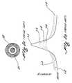
- FIG. 1is a schematic diagram showing red and blue spectral components of dispersed polychromatic light emerging from a diffractive lens in sharp focus at different focal planes along the optic axis.
- FIGS. 2 ( a ) and 2 ( b )show the intensity distribution of dispersed spectral components of light from a single point source illuminating a photosensitive surface and show the relative intensity of the in-focus spectral component having a wavelength ⁇ 1 with respect to the superimposed intensity of out-of-focus spectral components of the dispersed light at the focal plane of ⁇ 1 and generally illustrating the relationship between spectral resolution in of the in-focus image and the out-of-focus background.
- FIG. 3is a schematic diagram of an IMSS spectrophotometer showing the optical relationship of the addressable transmissive spatial mask ( 35 ) with respect to the input optics for controlling transmission of the image projected thereon to the diffractive lens ( 31 ) for dispersion and to the photodetector ( 32 ) for spectral detection.
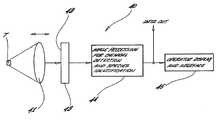
- FIG. 4is a schematic diagram of a gas detection instrument in accordance with the present invention, adapted for detecting gas leaks.
- the present inventionprovides an apparatus and method for identifying the presence of a gas leak at a location remote from the apparatus.
- the apparatusis a IMSS spectrometer incorporating an addressable spacial mask which permits the spectral composition of a single pixel to be determined even when the image comprises more than one independent source of light.
- a prior art IMSS systemis shown in FIG. 3 .
- the apparatus 30comprises a diffractive lens 31 having an optical axis, a photodetector 32 having a planar photosensitive surface orthogonal to the optical axis and intersecting the optical axis at a distance f from the diffractive lens, a stepping motor 33 , which may include an optional shaft position encoder, adapted to change D a known amount in response to a control signal, a programmable signal processor 34 which includes programmable computer means adapted to provide a control signal to the stepping motor 33 for changing D and provide control signals to the gates and identify and synchronously record the output signal of the pixel in optical communication with the gate.
- the signal processoris adapted to receive and organize the output signals from each pixel within the photodetector into a sequence of frames, each frame in the sequence containing the signal output of each pixel at a focal plane f corresponding to an input of the position encoder 33 identifying a focal plane, process the frames to spectrally filter the spectral data and present the processed spectral data to a spectral correlator 35 for comparison, identification storage, or for future reference purposes.
- Light 36 emanating from a remote target 37 within a field of viewis collimated by input optics 38 which directs the light 36 comprising an image of the field of view to impinge upon a diffractive lens 31 .
- the light 36is focused by the diffractive lens 31 onto the photodetector 32 .
- the distance f between the photodetector array 32 and the diffractive lens 31is controlled by mounting one of the components 31 or 32 on translating means 33 such as a stepper motor, a piezoelectric translation device or other such translating device capable of varying D to traverse the range of focal lengths encompassing the spectral components of the light 36 .
- the distance Dwhich is the instantaneous distance between the diffractive lens 31 and the photodetector 32 along the optic axis, is determined by a stepping motor 33 , which is controlled by the signal processor 34 .
- the signal processorrecords the signal output of each pixel (not shown in FIG. 3) in the photodetector 32 .
- the relative intensity and wavelength of the spectral components ⁇ 1 - ⁇ 9 of the light 36 emanating from the target 37may be compared with spectral data stored within the memory of a spectral correlator 35 .
- the correlator 35provides a means for storing and comparing spectral data.
- the signal output of each pixel within the photodetector array 12is electronically scanned into a signal processor 34 .
- the signal processorcompares the signal output of each pixel with the signal output of pixels immediately adjacent thereto. If the signal output of the adjacent pixels is uniformly lower than the output of the pixel being processed, the uniform output signal may be attributed to noise and subtracted from the measured signal output of the pixel to provide a measure of the intensity of the in-focus spectral component.
- the processis repeated for each pixel having a signal output greater than a threshold value and the electronically filtered spectral intensity data is stored in a frame.
- the procedureis repeated at incremental focal planes until frames encompassing the spectral range of interest are recorded. For example, with reference to FIG.
- the change in distance between the diffractive lens and the photodetector required for IMSSmust be sufficient to span the range of focal lengths for the spectral components of interest in the target-derived light.
- a piezoelectric driven movable elementmay be used to mount the diffractive lens. Focal length scans of 160 millimeters per second are practical with this approach.
- a stepper motor or a pneumatic/hydraulic translational devicecan also be employed for changing the distance f between the diffractive element and the photodetector when either of the components are moved thereby thereon.
- the defocused spectral components of light comprising the spectra of nearby independent sources of light within the imagewill also impose noise upon a pixel's output signal. If the out-of-focus spectral component from an adjacent target is very intense, it can dramatically and asymmetrically effect the signal output of the pixel receiving the in-focus spectral component of the less luminous light source.
- the apparatusemploys an addressable spatial mask, shown in phantom at 35 in FIG. 3, disposed between the input optics 38 and the diffractive lens 11 to shadow one of a plurality of adjacent light sources in an image to reduce interspectral noise at the photodetector.
- the maskhas an image receiving surface which consists of a planar array of discrete, addressable, independently controllable optical gates disposed to receive an image projected thereon by the input optics.
- the function of the maskis to select only a pixel-sized portion of the image incident thereon and sequentially direct the gated pixel-sized portion of the image to be dispersed by the diffractive lens.
- the diffractive lensfocuses the spectral components to illuminate the photodetector. Light from other portions of the image are blocked out while the signal output of the pixel receiving the gated light is synchronously recorded.
- Each of the plurality of switchable gates forming the image-receiving surface of the maskare sequentially “switched” in response to a control signal from the signal processor and will direct only the portion of the image incident thereon to the diffractive lens in synchronization with the electronic readout of the pixel upon which the gated light is focused.
- each spectral component comprising the imageis sequentially mapped onto the photodetector surface a “gate-full” at a time in synchronization with the sequential output sampling of the gate-sized pixel in the photodetector upon which the gated light is focused. Out-of-focus light from other spatially separated portions of the image is blocked out.
- a diffractive optical element 41is used to focus an image of the target chemical under analysis on a photosensitive surface 42 of a detector 43 (such as a focal plane array (FPA)).
- a detector 43such as a focal plane array (FPA)
- An image of the scene under viewis formed on the detector 43 .
- the IMSS diffractive optical element 41focuses different wavelengths of light at different distances or focal lengths.
- the distance between the diffractive optical element 41 and the detector 43is changed to form a series of very narrowband spectral images.
- the imagesare stored in the image processing electronics 44 .
- the image processing electronics 44uses these spectral images to detect and image the target chemical by techniques such as, for example, by comparing the image at the absorption band of the target chemical to images outside the absorption band, using motion detection algorithms, and applying techniques such as principle components analysis.
- a raw image and a processed image of the target chemicalcan be provided to the operator via operator display 45 .
- the instrument 40can also identify an unknown chemical.
- the spectrum of an unknown target chemical obtained by the instrumentis compared with a spectral database of chemical spectra stored in the image processing electronics to identify the chemical species of the target chemical.
- Concentrations of the target chemicalare obtained by determining the absorption (or emission in the case of a flame or plume) of the target chemical at its absorption wavelength (or emission wavelength) compared to images outside the absorption or emission region.
- a diffractive lensfor the chromatic dispersion of light wherein the particular wavelength of light in focus at a particular point in space depends on the electromechanical forces applied to the lens.
- a diffractive optical elementcan be made using polymer or spatial light modulators which change the characteristics of the lens such that the chromatic focal length of the lens can be adjusted by application of an appropriate electrical signal to the lens.
Landscapes
- Physics & Mathematics (AREA)
- Spectroscopy & Molecular Physics (AREA)
- General Physics & Mathematics (AREA)
- Analytical Chemistry (AREA)
- Life Sciences & Earth Sciences (AREA)
- Chemical & Material Sciences (AREA)
- Health & Medical Sciences (AREA)
- Biochemistry (AREA)
- General Health & Medical Sciences (AREA)
- Immunology (AREA)
- Pathology (AREA)
- Spectrometry And Color Measurement (AREA)
- Investigating Or Analysing Materials By Optical Means (AREA)
Abstract
Description
Claims (5)
Priority Applications (1)
| Application Number | Priority Date | Filing Date | Title |
|---|---|---|---|
| US10/007,080US6680778B2 (en) | 2001-11-08 | 2001-11-08 | Gas leak detector |
Applications Claiming Priority (1)
| Application Number | Priority Date | Filing Date | Title |
|---|---|---|---|
| US10/007,080US6680778B2 (en) | 2001-11-08 | 2001-11-08 | Gas leak detector |
Publications (2)
| Publication Number | Publication Date |
|---|---|
| US20030086091A1 US20030086091A1 (en) | 2003-05-08 |
| US6680778B2true US6680778B2 (en) | 2004-01-20 |
Family
ID=21724111
Family Applications (1)
| Application Number | Title | Priority Date | Filing Date |
|---|---|---|---|
| US10/007,080Expired - LifetimeUS6680778B2 (en) | 2001-11-08 | 2001-11-08 | Gas leak detector |
Country Status (1)
| Country | Link |
|---|---|
| US (1) | US6680778B2 (en) |
Cited By (37)
| Publication number | Priority date | Publication date | Assignee | Title |
|---|---|---|---|---|
| US7060992B1 (en) | 2003-03-10 | 2006-06-13 | Tiax Llc | System and method for bioaerosol discrimination by time-resolved fluorescence |
| US20060237665A1 (en)* | 2003-03-10 | 2006-10-26 | Barney William S | Bioaerosol discrimination |
| US20080251724A1 (en)* | 2007-04-11 | 2008-10-16 | Baliga Shankar B | Gas and/or flame imaging system |
| US20100284570A1 (en)* | 2008-01-08 | 2010-11-11 | Ernest Grimberg | System and method for gas leakage detection |
| US20110091094A1 (en)* | 2009-10-19 | 2011-04-21 | Jons Steven D | Method of testing the integrity of spiral wound modules |
| US20110170572A1 (en)* | 2010-01-12 | 2011-07-14 | Jons Steven D | Method of testing spiral wound modules by thermal imaging |
| US8034290B1 (en) | 2007-01-29 | 2011-10-11 | LDARtools, Inc. | Reigniting flame in volatile organic compound device |
| US8271208B1 (en) | 2008-05-29 | 2012-09-18 | LDARtools, Inc. | Flame ionization detector management system |
| US8274402B1 (en) | 2008-01-24 | 2012-09-25 | LDARtools, Inc. | Data collection process for optical leak detection |
| US8386164B1 (en)* | 2008-05-15 | 2013-02-26 | LDARtools, Inc. | Locating LDAR components using position coordinates |
| US8587319B1 (en) | 2010-10-08 | 2013-11-19 | LDARtools, Inc. | Battery operated flame ionization detector |
| US8653461B1 (en) | 2007-03-23 | 2014-02-18 | Flir Systems, Inc. | Thermography camera tuned to detect absorption of infrared radiation in a selected spectral bandwidth |
| US8659664B2 (en) | 2007-03-23 | 2014-02-25 | Flir Systems, Inc. | Thermography camera configured for leak detection |
| US8751173B1 (en) | 2007-03-28 | 2014-06-10 | LDARtools, Inc. | Management of response to triggering events in connection with monitoring fugitive emissions |
| US9488629B2 (en) | 2014-04-10 | 2016-11-08 | General Electric Company | Method for detecting coolant leaks in generators |
| US9562849B2 (en) | 2013-11-12 | 2017-02-07 | Rebellion Photonics, Inc. | Divided-aperture infra-red spectral imaging system |
| US9599508B2 (en) | 2012-05-18 | 2017-03-21 | Rebellion Photonics, Inc. | Divided-aperture infra-red spectral imaging system |
| US9625318B2 (en) | 2012-05-18 | 2017-04-18 | Rebellion Photonics, Inc. | Divided-aperture infra-red spectral imaging system for chemical detection |
| US9756263B2 (en) | 2014-05-01 | 2017-09-05 | Rebellion Photonics, Inc. | Mobile gas and chemical imaging camera |
| US10190976B2 (en) | 2017-03-16 | 2019-01-29 | MultiSensor Scientific, Inc. | Scanning IR sensor for gas safety and emissions monitoring |
| US10197470B2 (en) | 2016-05-18 | 2019-02-05 | MultiSensor Scientific, Inc. | Hydrocarbon leak imaging and quantification sensor |
| US10234354B2 (en) | 2014-03-28 | 2019-03-19 | Intelliview Technologies Inc. | Leak detection |
| US10295457B1 (en) | 2017-06-13 | 2019-05-21 | Larry Ocheltree | Airplane cabin air quality monitoring system |
| US10375327B2 (en) | 2016-10-21 | 2019-08-06 | Rebellion Photonics, Inc. | Mobile gas and chemical imaging camera |
| US10371627B2 (en) | 2017-11-16 | 2019-08-06 | MultiSensor Scientific, Inc. | Systems and methods for multispectral imaging and gas detection using a scanning illuminator and optical sensor |
| US10373470B2 (en) | 2013-04-29 | 2019-08-06 | Intelliview Technologies, Inc. | Object detection |
| US10458905B2 (en) | 2014-07-07 | 2019-10-29 | Rebellion Photonics, Inc. | Gas leak emission quantification with a gas cloud imager |
| US10488854B1 (en) | 2014-05-20 | 2019-11-26 | InspectionLogic Corporation | Method and determination for fugitive emissions monitoring time |
| US10605725B2 (en) | 2017-11-09 | 2020-03-31 | Rebellion Photonics, Inc. | Window obscuration sensors for mobile gas and chemical imaging cameras |
| US10648960B2 (en) | 2015-05-29 | 2020-05-12 | Rebellion Photonics, Inc. | Hydrogen sulfide imaging system |
| US10909364B2 (en) | 2015-12-07 | 2021-02-02 | Flir Systems, Inc. | Uncooled gas imaging camera |
| US10943357B2 (en) | 2014-08-19 | 2021-03-09 | Intelliview Technologies Inc. | Video based indoor leak detection |
| US10948404B2 (en) | 2016-10-21 | 2021-03-16 | Rebellion Photonics, Inc. | Gas imaging system |
| US10955355B2 (en) | 2017-02-22 | 2021-03-23 | Rebellion Photonics, Inc. | Systems and methods for monitoring remote installations |
| US10976245B2 (en) | 2019-01-25 | 2021-04-13 | MultiSensor Scientific, Inc. | Systems and methods for leak monitoring via measurement of optical absorption using tailored reflector installments |
| US11290662B2 (en) | 2014-05-01 | 2022-03-29 | Rebellion Photonics, Inc. | Mobile gas and chemical imaging camera |
| US11933774B1 (en)* | 2017-06-01 | 2024-03-19 | Picarro Inc. | Leak detection event aggregation and ranking systems and methods |
Families Citing this family (16)
| Publication number | Priority date | Publication date | Assignee | Title |
|---|---|---|---|---|
| US6791088B1 (en)* | 2001-05-04 | 2004-09-14 | Twin Rivers Engineering, Inc. | Infrared leak detector |
| EP1639332A2 (en) | 2003-06-11 | 2006-03-29 | Furry Brothers, LLC | Systems and methods for performing inspections and detecting chemical leaks using an infrared camera system |
| DE502004005081D1 (en)* | 2004-07-01 | 2007-11-08 | Zeutec Opto Elektronik Gmbh | Device for the imaging spectroscopic detection of objects characterizing parameters |
| US20080092625A1 (en)* | 2004-07-27 | 2008-04-24 | Michele Hinnrichs | Gas Leak Detector Having An Integral Data Logger |
| DE102005002106B3 (en)* | 2005-01-14 | 2006-04-13 | Drägerwerk AG | Spectroscopic device for qualitative and quantitative analysis of gas mixtures, useful in medical and safety applications, comprising refractive-diffractive elements for wavelength-dependent imaging |
| US20100181472A1 (en)* | 2007-04-09 | 2010-07-22 | Baker Hughes Incorporated | Method and Apparatus to Determine Characteristics of an Oil-Based Mud Downhole |
| US20080245960A1 (en)* | 2007-04-09 | 2008-10-09 | Baker Hughes Incorporated | Method and Apparatus to Determine Characteristics of an Oil-Based Mud Downhole |
| US8487238B2 (en)* | 2007-11-01 | 2013-07-16 | Baker Hughes Incorporated | Method of identification of petroleum compounds using frequency mixing on surfaces |
| CN102609906A (en)* | 2012-01-12 | 2012-07-25 | 北京理工大学 | Gas infrared image enhancing method based on anisotropic diffusion |
| US8930341B2 (en)* | 2012-05-07 | 2015-01-06 | Alexander Himanshu Amin | Mobile communications device with electronic nose |
| US9723230B2 (en) | 2012-11-30 | 2017-08-01 | University Of Utah Research Foundation | Multi-spectral imaging with diffractive optics |
| US9523609B2 (en) | 2013-04-10 | 2016-12-20 | Bae Systems Plc | Spectral imaging |
| EP2789999A1 (en)* | 2013-04-10 | 2014-10-15 | BAE Systems PLC | Spectral imaging |
| CN107941728A (en)* | 2017-12-29 | 2018-04-20 | 青岛崂应环境科技有限公司 | Open path gas concentration analysis and device |
| WO2024233562A1 (en)* | 2023-05-08 | 2024-11-14 | Trellisense, Inc. | Gaseous leak detection system and associated methods |
| CN118674830A (en)* | 2024-03-18 | 2024-09-20 | 四川弘和数智集团有限公司 | Method, device, equipment and medium for generating gas leakage image of oil and gas station compressor |
Citations (5)
| Publication number | Priority date | Publication date | Assignee | Title |
|---|---|---|---|---|
| US4147431A (en)* | 1976-04-26 | 1979-04-03 | Varian Associates, Inc. | Apparatus and method for measuring pressures and indicating leaks with optical analysis |
| US5015099A (en)* | 1989-03-23 | 1991-05-14 | Anritsu Corporation | Differential absorption laser radar gas detection apparatus having tunable wavelength single mode semiconductor laser source |
| US5479258A (en)* | 1992-12-28 | 1995-12-26 | Pat Industries | Image multispectral sensing |
| US5867264A (en)* | 1997-10-15 | 1999-02-02 | Pacific Advanced Technology | Apparatus for image multispectral sensing employing addressable spatial mask |
| US5892586A (en)* | 1996-04-04 | 1999-04-06 | Commissariat A L'energie Atomique | Remote gas detection apparatus having a microlaser |
- 2001
- 2001-11-08USUS10/007,080patent/US6680778B2/ennot_activeExpired - Lifetime
Patent Citations (5)
| Publication number | Priority date | Publication date | Assignee | Title |
|---|---|---|---|---|
| US4147431A (en)* | 1976-04-26 | 1979-04-03 | Varian Associates, Inc. | Apparatus and method for measuring pressures and indicating leaks with optical analysis |
| US5015099A (en)* | 1989-03-23 | 1991-05-14 | Anritsu Corporation | Differential absorption laser radar gas detection apparatus having tunable wavelength single mode semiconductor laser source |
| US5479258A (en)* | 1992-12-28 | 1995-12-26 | Pat Industries | Image multispectral sensing |
| US5892586A (en)* | 1996-04-04 | 1999-04-06 | Commissariat A L'energie Atomique | Remote gas detection apparatus having a microlaser |
| US5867264A (en)* | 1997-10-15 | 1999-02-02 | Pacific Advanced Technology | Apparatus for image multispectral sensing employing addressable spatial mask |
Cited By (89)
| Publication number | Priority date | Publication date | Assignee | Title |
|---|---|---|---|---|
| US7060992B1 (en) | 2003-03-10 | 2006-06-13 | Tiax Llc | System and method for bioaerosol discrimination by time-resolved fluorescence |
| US20060237665A1 (en)* | 2003-03-10 | 2006-10-26 | Barney William S | Bioaerosol discrimination |
| US8329099B1 (en) | 2007-01-29 | 2012-12-11 | LDARtools, Inc. | Reigniting flame in volatile organic compound device |
| US8034290B1 (en) | 2007-01-29 | 2011-10-11 | LDARtools, Inc. | Reigniting flame in volatile organic compound device |
| US9635284B2 (en) | 2007-03-23 | 2017-04-25 | Flir Systems, Inc. | Thermography camera tuned to detect absorption of infrared radiation in a selected spectral bandwidth |
| US8659664B2 (en) | 2007-03-23 | 2014-02-25 | Flir Systems, Inc. | Thermography camera configured for leak detection |
| US8653461B1 (en) | 2007-03-23 | 2014-02-18 | Flir Systems, Inc. | Thermography camera tuned to detect absorption of infrared radiation in a selected spectral bandwidth |
| US9276161B2 (en) | 2007-03-23 | 2016-03-01 | Flir Systems, Inc. | Thermography camera tuned to detect absorption of infrared radiation in a selected spectral bandwidth |
| US8751173B1 (en) | 2007-03-28 | 2014-06-10 | LDARtools, Inc. | Management of response to triggering events in connection with monitoring fugitive emissions |
| US7687776B2 (en) | 2007-04-11 | 2010-03-30 | General Monitors, Inc. | Gas and/or flame imaging system with explosion proof housing |
| US20080251724A1 (en)* | 2007-04-11 | 2008-10-16 | Baliga Shankar B | Gas and/or flame imaging system |
| US20100284570A1 (en)* | 2008-01-08 | 2010-11-11 | Ernest Grimberg | System and method for gas leakage detection |
| US8548271B2 (en) | 2008-01-08 | 2013-10-01 | Opgal Optronic Industries Ltd. | System and method for gas leakage detection |
| US8866637B1 (en) | 2008-01-24 | 2014-10-21 | LDARtools, Inc. | Data collection process for optical leak detection |
| US8274402B1 (en) | 2008-01-24 | 2012-09-25 | LDARtools, Inc. | Data collection process for optical leak detection |
| US8386164B1 (en)* | 2008-05-15 | 2013-02-26 | LDARtools, Inc. | Locating LDAR components using position coordinates |
| US8271208B1 (en) | 2008-05-29 | 2012-09-18 | LDARtools, Inc. | Flame ionization detector management system |
| US8571296B2 (en) | 2009-10-19 | 2013-10-29 | Dow Global Technologies Llc | Method of testing the integrity of spiral wound modules |
| WO2011049790A1 (en) | 2009-10-19 | 2011-04-28 | Dow Global Technologies Llc | Method of testing the integrity of spiral wound modules |
| US20110091094A1 (en)* | 2009-10-19 | 2011-04-21 | Jons Steven D | Method of testing the integrity of spiral wound modules |
| WO2011087536A1 (en) | 2010-01-12 | 2011-07-21 | Dow Global Technologies Llc | Method of testing spiral wound modules by thermal imaging |
| US8348499B2 (en) | 2010-01-12 | 2013-01-08 | Dow Global Technologies Llc | Method of testing spiral wound modules by thermal imaging |
| US20110170572A1 (en)* | 2010-01-12 | 2011-07-14 | Jons Steven D | Method of testing spiral wound modules by thermal imaging |
| US8587319B1 (en) | 2010-10-08 | 2013-11-19 | LDARtools, Inc. | Battery operated flame ionization detector |
| US11879775B2 (en) | 2012-05-18 | 2024-01-23 | Rebellion Photonics, Inc. | Divided-aperture infra-red spectral imaging system |
| US9599508B2 (en) | 2012-05-18 | 2017-03-21 | Rebellion Photonics, Inc. | Divided-aperture infra-red spectral imaging system |
| US9625318B2 (en) | 2012-05-18 | 2017-04-18 | Rebellion Photonics, Inc. | Divided-aperture infra-red spectral imaging system for chemical detection |
| US10914632B2 (en) | 2012-05-18 | 2021-02-09 | Rebellion Photonics, Inc. | Divided-aperture infra-red spectral imaging system |
| US10989597B2 (en) | 2012-05-18 | 2021-04-27 | Rebellion Photonics, Inc. | Divided-aperture infra-red spectral imaging system for chemical detection |
| US11313724B2 (en) | 2012-05-18 | 2022-04-26 | Rebellion Photonics, Inc. | Divided-aperture infra-red spectral imaging system for chemical detection |
| US11821792B2 (en) | 2012-05-18 | 2023-11-21 | Rebellion Photonics, Inc. | Divided-aperture infra-red spectral imaging system for chemical detection |
| US12411042B2 (en) | 2012-05-18 | 2025-09-09 | Rebellion Photonics, Inc. | Divided-aperture infra-red spectral imaging system |
| US10444070B2 (en) | 2012-05-18 | 2019-10-15 | Rebellion Photonics, Inc. | Divided-aperture infra-red spectral imaging system |
| US10254166B2 (en) | 2012-05-18 | 2019-04-09 | Rebellion Photonics, Inc. | Divided-aperture infra-red spectral imaging system for chemical detection |
| US10373470B2 (en) | 2013-04-29 | 2019-08-06 | Intelliview Technologies, Inc. | Object detection |
| US20170205290A1 (en) | 2013-11-12 | 2017-07-20 | Rebellion Photonics, Inc. | Divided-aperture infra-red spectral imaging system |
| US10914639B2 (en) | 2013-11-12 | 2021-02-09 | Rebellion Photonics, Inc. | Divided-aperture infra-red spectral imaging system |
| US11326957B2 (en) | 2013-11-12 | 2022-05-10 | Rebellion Photonics, Inc. | Divided-aperture infra-red spectral imaging system |
| US10267686B2 (en) | 2013-11-12 | 2019-04-23 | Rebellion Photonics, Inc. | Divided-aperture infra-red spectral imaging system |
| US9562849B2 (en) | 2013-11-12 | 2017-02-07 | Rebellion Photonics, Inc. | Divided-aperture infra-red spectral imaging system |
| US11867564B2 (en) | 2013-11-12 | 2024-01-09 | Rebellion Photonics, Inc. | Divided-aperture infra-red spectral imaging system |
| US12326371B2 (en) | 2013-11-12 | 2025-06-10 | Rebellion Photonics, Inc. | Divided-aperture infra-red spectral imaging system |
| US10234354B2 (en) | 2014-03-28 | 2019-03-19 | Intelliview Technologies Inc. | Leak detection |
| US9488629B2 (en) | 2014-04-10 | 2016-11-08 | General Electric Company | Method for detecting coolant leaks in generators |
| US10893220B2 (en) | 2014-05-01 | 2021-01-12 | Rebellion Photonics, Inc. | Dual-band divided-aperture infra-red spectral imaging system |
| US9756263B2 (en) | 2014-05-01 | 2017-09-05 | Rebellion Photonics, Inc. | Mobile gas and chemical imaging camera |
| US10834338B2 (en) | 2014-05-01 | 2020-11-10 | Rebllion Photonics, Inc. | Mobile gas and chemical imaging camera |
| US11805221B2 (en) | 2014-05-01 | 2023-10-31 | Rebellion Photonics, Inc. | Dual-band divided-aperture infra-red spectral imaging system |
| US10084975B2 (en) | 2014-05-01 | 2018-09-25 | Rebellion Photonics, Inc. | Mobile gas and chemical imaging camera |
| US12316995B2 (en) | 2014-05-01 | 2025-05-27 | Rebellion Photonics, Inc. | Mobile gas and chemical imaging camera |
| US11917321B2 (en) | 2014-05-01 | 2024-02-27 | Rebellion Photonics, Inc. | Mobile gas and chemical imaging camera |
| US11290662B2 (en) | 2014-05-01 | 2022-03-29 | Rebellion Photonics, Inc. | Mobile gas and chemical imaging camera |
| US10871771B1 (en) | 2014-05-20 | 2020-12-22 | InspectionLogic Corporation | Method and determination for fugitive emissions monitoring time |
| US10488854B1 (en) | 2014-05-20 | 2019-11-26 | InspectionLogic Corporation | Method and determination for fugitive emissions monitoring time |
| US10458905B2 (en) | 2014-07-07 | 2019-10-29 | Rebellion Photonics, Inc. | Gas leak emission quantification with a gas cloud imager |
| US11796454B2 (en) | 2014-07-07 | 2023-10-24 | Rebellion Photonics, Inc. | Gas leak emission quantification with a gas cloud imager |
| US10943357B2 (en) | 2014-08-19 | 2021-03-09 | Intelliview Technologies Inc. | Video based indoor leak detection |
| US10648960B2 (en) | 2015-05-29 | 2020-05-12 | Rebellion Photonics, Inc. | Hydrogen sulfide imaging system |
| US11846619B2 (en) | 2015-05-29 | 2023-12-19 | Rebellion Photonics, Inc. | Hydrogen sulfide imaging system |
| US11287409B2 (en) | 2015-05-29 | 2022-03-29 | Rebellion Photonics, Inc. | Hydrogen sulfide imaging system |
| US12326430B2 (en) | 2015-05-29 | 2025-06-10 | Rebellion Photonics, Inc. | Hydrogen sulfide imaging system |
| US10909364B2 (en) | 2015-12-07 | 2021-02-02 | Flir Systems, Inc. | Uncooled gas imaging camera |
| US11143572B2 (en) | 2016-05-18 | 2021-10-12 | MultiSensor Scientific, Inc. | Hydrocarbon leak imaging and quantification sensor |
| US10197470B2 (en) | 2016-05-18 | 2019-02-05 | MultiSensor Scientific, Inc. | Hydrocarbon leak imaging and quantification sensor |
| US11733158B2 (en) | 2016-10-21 | 2023-08-22 | Rebellion Photonics, Inc. | Gas imaging system |
| US12385828B2 (en) | 2016-10-21 | 2025-08-12 | Rebellion Photonics, Inc. | Gas imaging system |
| US10375327B2 (en) | 2016-10-21 | 2019-08-06 | Rebellion Photonics, Inc. | Mobile gas and chemical imaging camera |
| US10948404B2 (en) | 2016-10-21 | 2021-03-16 | Rebellion Photonics, Inc. | Gas imaging system |
| US11044423B2 (en) | 2016-10-21 | 2021-06-22 | Rebellion Photonics, Inc. | Mobile gas and chemical imaging camera |
| US12174067B2 (en) | 2016-10-21 | 2024-12-24 | Rebellion Photonics, Inc. | Mobile gas and chemical imaging camera |
| US11467098B2 (en) | 2017-02-22 | 2022-10-11 | Rebellion Photonics, Inc. | Systems and methods for monitoring remote installations |
| US10955355B2 (en) | 2017-02-22 | 2021-03-23 | Rebellion Photonics, Inc. | Systems and methods for monitoring remote installations |
| US10436710B2 (en) | 2017-03-16 | 2019-10-08 | MultiSensor Scientific, Inc. | Scanning IR sensor for gas safety and emissions monitoring |
| US10190976B2 (en) | 2017-03-16 | 2019-01-29 | MultiSensor Scientific, Inc. | Scanning IR sensor for gas safety and emissions monitoring |
| US11933774B1 (en)* | 2017-06-01 | 2024-03-19 | Picarro Inc. | Leak detection event aggregation and ranking systems and methods |
| US10295457B1 (en) | 2017-06-13 | 2019-05-21 | Larry Ocheltree | Airplane cabin air quality monitoring system |
| US11933723B2 (en) | 2017-11-09 | 2024-03-19 | Rebellion Photonics, Inc. | Window obscuration sensors for mobile gas and chemical imaging cameras |
| US10605725B2 (en) | 2017-11-09 | 2020-03-31 | Rebellion Photonics, Inc. | Window obscuration sensors for mobile gas and chemical imaging cameras |
| US11698339B2 (en) | 2017-11-09 | 2023-07-11 | Rebellion Photonics, Inc. | Window obscuration sensors for mobile gas and chemical imaging cameras |
| US12000776B2 (en) | 2017-11-09 | 2024-06-04 | Rebellion Photonics, Inc. | Window obscuration sensors for mobile gas and chemical imaging cameras |
| US11624705B2 (en) | 2017-11-09 | 2023-04-11 | Rebellion Photonics, Inc. | Window obscuration sensors for mobile gas and chemical imaging cameras |
| US11391671B2 (en) | 2017-11-09 | 2022-07-19 | Rebellion Photonics, Inc. | Window obscuration sensors for mobile gas and chemical imaging cameras |
| US12372459B2 (en) | 2017-11-09 | 2025-07-29 | Rebellion Photonics, Inc. | Window obscuration sensors for mobile gas and chemical imaging cameras |
| US11313791B2 (en) | 2017-11-09 | 2022-04-26 | Rebellion Photonics, Inc. | Window obscuration sensors for mobile gas and chemical imaging cameras |
| US10371627B2 (en) | 2017-11-16 | 2019-08-06 | MultiSensor Scientific, Inc. | Systems and methods for multispectral imaging and gas detection using a scanning illuminator and optical sensor |
| US10921243B2 (en) | 2017-11-16 | 2021-02-16 | MultiSensor Scientific, Inc. | Systems and methods for multispectral imaging and gas detection using a scanning illuminator and optical sensor |
| US11686677B2 (en) | 2019-01-25 | 2023-06-27 | MultiSensor Scientific, Inc. | Systems and methods for leak monitoring via measurement of optical absorption using tailored reflector installments |
| US11493437B2 (en) | 2019-01-25 | 2022-11-08 | MultiSensor Scientific, Inc. | Systems and methods for leak monitoring via measurement of optical absorption using tailored reflector installments |
| US10976245B2 (en) | 2019-01-25 | 2021-04-13 | MultiSensor Scientific, Inc. | Systems and methods for leak monitoring via measurement of optical absorption using tailored reflector installments |
Also Published As
| Publication number | Publication date |
|---|---|
| US20030086091A1 (en) | 2003-05-08 |
Similar Documents
| Publication | Publication Date | Title |
|---|---|---|
| US6680778B2 (en) | Gas leak detector | |
| EP0746746B1 (en) | Image multispectral sensing | |
| US7692784B2 (en) | Apparatus and methods relating to enhanced spectral measurement systems | |
| US7248358B2 (en) | Devices and method for spectral measurements | |
| US6690466B2 (en) | Spectral imaging system | |
| Hyvarinen et al. | Direct sight imaging spectrograph: a unique add-in component brings spectral imaging to industrial applications | |
| JP6676398B2 (en) | Colorimetric system for display inspection | |
| US5717487A (en) | Compact fast imaging spectrometer | |
| US7652765B1 (en) | Hyper-spectral imaging methods and devices | |
| US7420679B2 (en) | Method and apparatus for extended hyperspectral imaging | |
| US7012633B2 (en) | Color calibration method for imaging color measurement device | |
| US20050270528A1 (en) | Hyper-spectral imaging methods and devices | |
| US7414717B2 (en) | System and method for detection and identification of optical spectra | |
| US6208413B1 (en) | Hadamard spectrometer | |
| US20070171409A1 (en) | Method and apparatus for dense spectrum unmixing and image reconstruction of a sample | |
| CN113544491B (en) | Method for generating a frequency-corrected hyperspectral image of a sample | |
| US12271004B2 (en) | Imager and spot sampler with translatable stage | |
| EP1381847A2 (en) | Hybrid-imaging spectrometer | |
| CN112556849B (en) | Hyperspectral imaging device | |
| US20060221335A1 (en) | Method and apparatus for interactive hyperspectral image subtraction | |
| TR2024011625U5 (en) | SPECTROSCOPIC IMAGE PROCESSING METHOD AND DUAL CHANNEL SPECTROMETRY SYSTEMS FOR FORENSIC AND MARKER EXAMINATIONS | |
| KR20220112030A (en) | Multiple fiber-adapted spectrometer for large area sample Measurement |
Legal Events
| Date | Code | Title | Description |
|---|---|---|---|
| STCF | Information on status: patent grant | Free format text:PATENTED CASE | |
| FEPP | Fee payment procedure | Free format text:PAYOR NUMBER ASSIGNED (ORIGINAL EVENT CODE: ASPN); ENTITY STATUS OF PATENT OWNER: SMALL ENTITY | |
| FEPP | Fee payment procedure | Free format text:PAYER NUMBER DE-ASSIGNED (ORIGINAL EVENT CODE: RMPN); ENTITY STATUS OF PATENT OWNER: SMALL ENTITY Free format text:PAYOR NUMBER ASSIGNED (ORIGINAL EVENT CODE: ASPN); ENTITY STATUS OF PATENT OWNER: SMALL ENTITY | |
| REMI | Maintenance fee reminder mailed | ||
| FPAY | Fee payment | Year of fee payment:4 | |
| SULP | Surcharge for late payment | ||
| AS | Assignment | Owner name:PACIFIC ADVANCED TECHNOLOGY, CALIFORNIA Free format text:ASSIGNMENT OF ASSIGNORS INTEREST;ASSIGNORS:HINNRICHS, MICHELE;HINNRICHS, ROBERT;REEL/FRAME:020842/0435;SIGNING DATES FROM 20031219 TO 20040109 | |
| FPAY | Fee payment | Year of fee payment:8 | |
| FPAY | Fee payment | Year of fee payment:12 | |
| AS | Assignment | Owner name:UVIA GROUP LLC, PUERTO RICO Free format text:ASSIGNMENT OF ASSIGNORS INTEREST;ASSIGNOR:PACIFIC ADVANCED TECHNOLOGY;REEL/FRAME:036137/0497 Effective date:20150714 |