US6679915B1 - Articulating spinal implant - Google Patents
Articulating spinal implantDownload PDFInfo
- Publication number
- US6679915B1 US6679915B1US09/513,954US51395400AUS6679915B1US 6679915 B1US6679915 B1US 6679915B1US 51395400 AUS51395400 AUS 51395400AUS 6679915 B1US6679915 B1US 6679915B1
- Authority
- US
- United States
- Prior art keywords
- vertebra
- articulation
- spinal implant
- implant according
- articulating
- Prior art date
- Legal status (The legal status is an assumption and is not a legal conclusion. Google has not performed a legal analysis and makes no representation as to the accuracy of the status listed.)
- Expired - Fee Related
Links
Images


Classifications
- A—HUMAN NECESSITIES
- A61—MEDICAL OR VETERINARY SCIENCE; HYGIENE
- A61F—FILTERS IMPLANTABLE INTO BLOOD VESSELS; PROSTHESES; DEVICES PROVIDING PATENCY TO, OR PREVENTING COLLAPSING OF, TUBULAR STRUCTURES OF THE BODY, e.g. STENTS; ORTHOPAEDIC, NURSING OR CONTRACEPTIVE DEVICES; FOMENTATION; TREATMENT OR PROTECTION OF EYES OR EARS; BANDAGES, DRESSINGS OR ABSORBENT PADS; FIRST-AID KITS
- A61F2/00—Filters implantable into blood vessels; Prostheses, i.e. artificial substitutes or replacements for parts of the body; Appliances for connecting them with the body; Devices providing patency to, or preventing collapsing of, tubular structures of the body, e.g. stents
- A61F2/02—Prostheses implantable into the body
- A61F2/30—Joints
- A61F2/44—Joints for the spine, e.g. vertebrae, spinal discs
- A61F2/442—Intervertebral or spinal discs, e.g. resilient
- A61F2/4425—Intervertebral or spinal discs, e.g. resilient made of articulated components
- A—HUMAN NECESSITIES
- A61—MEDICAL OR VETERINARY SCIENCE; HYGIENE
- A61B—DIAGNOSIS; SURGERY; IDENTIFICATION
- A61B17/00—Surgical instruments, devices or methods
- A61B17/16—Instruments for performing osteoclasis; Drills or chisels for bones; Trepans
- A61B17/1662—Instruments for performing osteoclasis; Drills or chisels for bones; Trepans for particular parts of the body
- A61B17/1671—Instruments for performing osteoclasis; Drills or chisels for bones; Trepans for particular parts of the body for the spine
- A—HUMAN NECESSITIES
- A61—MEDICAL OR VETERINARY SCIENCE; HYGIENE
- A61F—FILTERS IMPLANTABLE INTO BLOOD VESSELS; PROSTHESES; DEVICES PROVIDING PATENCY TO, OR PREVENTING COLLAPSING OF, TUBULAR STRUCTURES OF THE BODY, e.g. STENTS; ORTHOPAEDIC, NURSING OR CONTRACEPTIVE DEVICES; FOMENTATION; TREATMENT OR PROTECTION OF EYES OR EARS; BANDAGES, DRESSINGS OR ABSORBENT PADS; FIRST-AID KITS
- A61F2/00—Filters implantable into blood vessels; Prostheses, i.e. artificial substitutes or replacements for parts of the body; Appliances for connecting them with the body; Devices providing patency to, or preventing collapsing of, tubular structures of the body, e.g. stents
- A61F2/02—Prostheses implantable into the body
- A61F2/30—Joints
- A61F2/44—Joints for the spine, e.g. vertebrae, spinal discs
- A61F2/4455—Joints for the spine, e.g. vertebrae, spinal discs for the fusion of spinal bodies, e.g. intervertebral fusion of adjacent spinal bodies, e.g. fusion cages
- A61F2/446—Joints for the spine, e.g. vertebrae, spinal discs for the fusion of spinal bodies, e.g. intervertebral fusion of adjacent spinal bodies, e.g. fusion cages having a circular or elliptical cross-section substantially parallel to the axis of the spine, e.g. cylinders or frustocones
- A—HUMAN NECESSITIES
- A61—MEDICAL OR VETERINARY SCIENCE; HYGIENE
- A61B—DIAGNOSIS; SURGERY; IDENTIFICATION
- A61B17/00—Surgical instruments, devices or methods
- A61B17/16—Instruments for performing osteoclasis; Drills or chisels for bones; Trepans
- A61B17/1604—Chisels; Rongeurs; Punches; Stamps
- A—HUMAN NECESSITIES
- A61—MEDICAL OR VETERINARY SCIENCE; HYGIENE
- A61F—FILTERS IMPLANTABLE INTO BLOOD VESSELS; PROSTHESES; DEVICES PROVIDING PATENCY TO, OR PREVENTING COLLAPSING OF, TUBULAR STRUCTURES OF THE BODY, e.g. STENTS; ORTHOPAEDIC, NURSING OR CONTRACEPTIVE DEVICES; FOMENTATION; TREATMENT OR PROTECTION OF EYES OR EARS; BANDAGES, DRESSINGS OR ABSORBENT PADS; FIRST-AID KITS
- A61F2/00—Filters implantable into blood vessels; Prostheses, i.e. artificial substitutes or replacements for parts of the body; Appliances for connecting them with the body; Devices providing patency to, or preventing collapsing of, tubular structures of the body, e.g. stents
- A61F2/02—Prostheses implantable into the body
- A61F2/30—Joints
- A61F2/30721—Accessories
- A61F2/30724—Spacers for centering an implant in a bone cavity, e.g. in a cement-receiving cavity
- A—HUMAN NECESSITIES
- A61—MEDICAL OR VETERINARY SCIENCE; HYGIENE
- A61F—FILTERS IMPLANTABLE INTO BLOOD VESSELS; PROSTHESES; DEVICES PROVIDING PATENCY TO, OR PREVENTING COLLAPSING OF, TUBULAR STRUCTURES OF THE BODY, e.g. STENTS; ORTHOPAEDIC, NURSING OR CONTRACEPTIVE DEVICES; FOMENTATION; TREATMENT OR PROTECTION OF EYES OR EARS; BANDAGES, DRESSINGS OR ABSORBENT PADS; FIRST-AID KITS
- A61F2/00—Filters implantable into blood vessels; Prostheses, i.e. artificial substitutes or replacements for parts of the body; Appliances for connecting them with the body; Devices providing patency to, or preventing collapsing of, tubular structures of the body, e.g. stents
- A61F2/02—Prostheses implantable into the body
- A61F2/30—Joints
- A61F2/30721—Accessories
- A61F2/30744—End caps, e.g. for closing an endoprosthetic cavity
- A—HUMAN NECESSITIES
- A61—MEDICAL OR VETERINARY SCIENCE; HYGIENE
- A61F—FILTERS IMPLANTABLE INTO BLOOD VESSELS; PROSTHESES; DEVICES PROVIDING PATENCY TO, OR PREVENTING COLLAPSING OF, TUBULAR STRUCTURES OF THE BODY, e.g. STENTS; ORTHOPAEDIC, NURSING OR CONTRACEPTIVE DEVICES; FOMENTATION; TREATMENT OR PROTECTION OF EYES OR EARS; BANDAGES, DRESSINGS OR ABSORBENT PADS; FIRST-AID KITS
- A61F2/00—Filters implantable into blood vessels; Prostheses, i.e. artificial substitutes or replacements for parts of the body; Appliances for connecting them with the body; Devices providing patency to, or preventing collapsing of, tubular structures of the body, e.g. stents
- A61F2/02—Prostheses implantable into the body
- A61F2/30—Joints
- A61F2/30767—Special external or bone-contacting surface, e.g. coating for improving bone ingrowth
- A—HUMAN NECESSITIES
- A61—MEDICAL OR VETERINARY SCIENCE; HYGIENE
- A61F—FILTERS IMPLANTABLE INTO BLOOD VESSELS; PROSTHESES; DEVICES PROVIDING PATENCY TO, OR PREVENTING COLLAPSING OF, TUBULAR STRUCTURES OF THE BODY, e.g. STENTS; ORTHOPAEDIC, NURSING OR CONTRACEPTIVE DEVICES; FOMENTATION; TREATMENT OR PROTECTION OF EYES OR EARS; BANDAGES, DRESSINGS OR ABSORBENT PADS; FIRST-AID KITS
- A61F2/00—Filters implantable into blood vessels; Prostheses, i.e. artificial substitutes or replacements for parts of the body; Appliances for connecting them with the body; Devices providing patency to, or preventing collapsing of, tubular structures of the body, e.g. stents
- A61F2/02—Prostheses implantable into the body
- A61F2/30—Joints
- A61F2/44—Joints for the spine, e.g. vertebrae, spinal discs
- A61F2/442—Intervertebral or spinal discs, e.g. resilient
- A—HUMAN NECESSITIES
- A61—MEDICAL OR VETERINARY SCIENCE; HYGIENE
- A61F—FILTERS IMPLANTABLE INTO BLOOD VESSELS; PROSTHESES; DEVICES PROVIDING PATENCY TO, OR PREVENTING COLLAPSING OF, TUBULAR STRUCTURES OF THE BODY, e.g. STENTS; ORTHOPAEDIC, NURSING OR CONTRACEPTIVE DEVICES; FOMENTATION; TREATMENT OR PROTECTION OF EYES OR EARS; BANDAGES, DRESSINGS OR ABSORBENT PADS; FIRST-AID KITS
- A61F2/00—Filters implantable into blood vessels; Prostheses, i.e. artificial substitutes or replacements for parts of the body; Appliances for connecting them with the body; Devices providing patency to, or preventing collapsing of, tubular structures of the body, e.g. stents
- A61F2/02—Prostheses implantable into the body
- A61F2/30—Joints
- A61F2/46—Special tools for implanting artificial joints
- A61F2/4603—Special tools for implanting artificial joints for insertion or extraction of endoprosthetic joints or of accessories thereof
- A61F2/4611—Special tools for implanting artificial joints for insertion or extraction of endoprosthetic joints or of accessories thereof of spinal prostheses
- A—HUMAN NECESSITIES
- A61—MEDICAL OR VETERINARY SCIENCE; HYGIENE
- A61F—FILTERS IMPLANTABLE INTO BLOOD VESSELS; PROSTHESES; DEVICES PROVIDING PATENCY TO, OR PREVENTING COLLAPSING OF, TUBULAR STRUCTURES OF THE BODY, e.g. STENTS; ORTHOPAEDIC, NURSING OR CONTRACEPTIVE DEVICES; FOMENTATION; TREATMENT OR PROTECTION OF EYES OR EARS; BANDAGES, DRESSINGS OR ABSORBENT PADS; FIRST-AID KITS
- A61F2/00—Filters implantable into blood vessels; Prostheses, i.e. artificial substitutes or replacements for parts of the body; Appliances for connecting them with the body; Devices providing patency to, or preventing collapsing of, tubular structures of the body, e.g. stents
- A61F2/02—Prostheses implantable into the body
- A61F2/28—Bones
- A61F2002/2817—Bone stimulation by chemical reactions or by osteogenic or biological products for enhancing ossification, e.g. by bone morphogenetic or morphogenic proteins [BMP] or by transforming growth factors [TGF]
- A—HUMAN NECESSITIES
- A61—MEDICAL OR VETERINARY SCIENCE; HYGIENE
- A61F—FILTERS IMPLANTABLE INTO BLOOD VESSELS; PROSTHESES; DEVICES PROVIDING PATENCY TO, OR PREVENTING COLLAPSING OF, TUBULAR STRUCTURES OF THE BODY, e.g. STENTS; ORTHOPAEDIC, NURSING OR CONTRACEPTIVE DEVICES; FOMENTATION; TREATMENT OR PROTECTION OF EYES OR EARS; BANDAGES, DRESSINGS OR ABSORBENT PADS; FIRST-AID KITS
- A61F2/00—Filters implantable into blood vessels; Prostheses, i.e. artificial substitutes or replacements for parts of the body; Appliances for connecting them with the body; Devices providing patency to, or preventing collapsing of, tubular structures of the body, e.g. stents
- A61F2/02—Prostheses implantable into the body
- A61F2/28—Bones
- A61F2002/2821—Bone stimulation by electromagnetic fields or electric current for enhancing ossification
- A—HUMAN NECESSITIES
- A61—MEDICAL OR VETERINARY SCIENCE; HYGIENE
- A61F—FILTERS IMPLANTABLE INTO BLOOD VESSELS; PROSTHESES; DEVICES PROVIDING PATENCY TO, OR PREVENTING COLLAPSING OF, TUBULAR STRUCTURES OF THE BODY, e.g. STENTS; ORTHOPAEDIC, NURSING OR CONTRACEPTIVE DEVICES; FOMENTATION; TREATMENT OR PROTECTION OF EYES OR EARS; BANDAGES, DRESSINGS OR ABSORBENT PADS; FIRST-AID KITS
- A61F2/00—Filters implantable into blood vessels; Prostheses, i.e. artificial substitutes or replacements for parts of the body; Appliances for connecting them with the body; Devices providing patency to, or preventing collapsing of, tubular structures of the body, e.g. stents
- A61F2/02—Prostheses implantable into the body
- A61F2/28—Bones
- A61F2002/2835—Bone graft implants for filling a bony defect or an endoprosthesis cavity, e.g. by synthetic material or biological material
- A—HUMAN NECESSITIES
- A61—MEDICAL OR VETERINARY SCIENCE; HYGIENE
- A61F—FILTERS IMPLANTABLE INTO BLOOD VESSELS; PROSTHESES; DEVICES PROVIDING PATENCY TO, OR PREVENTING COLLAPSING OF, TUBULAR STRUCTURES OF THE BODY, e.g. STENTS; ORTHOPAEDIC, NURSING OR CONTRACEPTIVE DEVICES; FOMENTATION; TREATMENT OR PROTECTION OF EYES OR EARS; BANDAGES, DRESSINGS OR ABSORBENT PADS; FIRST-AID KITS
- A61F2/00—Filters implantable into blood vessels; Prostheses, i.e. artificial substitutes or replacements for parts of the body; Appliances for connecting them with the body; Devices providing patency to, or preventing collapsing of, tubular structures of the body, e.g. stents
- A61F2/02—Prostheses implantable into the body
- A61F2/30—Joints
- A61F2002/30001—Additional features of subject-matter classified in A61F2/28, A61F2/30 and subgroups thereof
- A61F2002/30003—Material related properties of the prosthesis or of a coating on the prosthesis
- A61F2002/3006—Properties of materials and coating materials
- A61F2002/30062—(bio)absorbable, biodegradable, bioerodable, (bio)resorbable, resorptive
- A—HUMAN NECESSITIES
- A61—MEDICAL OR VETERINARY SCIENCE; HYGIENE
- A61F—FILTERS IMPLANTABLE INTO BLOOD VESSELS; PROSTHESES; DEVICES PROVIDING PATENCY TO, OR PREVENTING COLLAPSING OF, TUBULAR STRUCTURES OF THE BODY, e.g. STENTS; ORTHOPAEDIC, NURSING OR CONTRACEPTIVE DEVICES; FOMENTATION; TREATMENT OR PROTECTION OF EYES OR EARS; BANDAGES, DRESSINGS OR ABSORBENT PADS; FIRST-AID KITS
- A61F2/00—Filters implantable into blood vessels; Prostheses, i.e. artificial substitutes or replacements for parts of the body; Appliances for connecting them with the body; Devices providing patency to, or preventing collapsing of, tubular structures of the body, e.g. stents
- A61F2/02—Prostheses implantable into the body
- A61F2/30—Joints
- A61F2002/30001—Additional features of subject-matter classified in A61F2/28, A61F2/30 and subgroups thereof
- A61F2002/30108—Shapes
- A61F2002/3011—Cross-sections or two-dimensional shapes
- A61F2002/30112—Rounded shapes, e.g. with rounded corners
- A61F2002/30125—Rounded shapes, e.g. with rounded corners elliptical or oval
- A—HUMAN NECESSITIES
- A61—MEDICAL OR VETERINARY SCIENCE; HYGIENE
- A61F—FILTERS IMPLANTABLE INTO BLOOD VESSELS; PROSTHESES; DEVICES PROVIDING PATENCY TO, OR PREVENTING COLLAPSING OF, TUBULAR STRUCTURES OF THE BODY, e.g. STENTS; ORTHOPAEDIC, NURSING OR CONTRACEPTIVE DEVICES; FOMENTATION; TREATMENT OR PROTECTION OF EYES OR EARS; BANDAGES, DRESSINGS OR ABSORBENT PADS; FIRST-AID KITS
- A61F2/00—Filters implantable into blood vessels; Prostheses, i.e. artificial substitutes or replacements for parts of the body; Appliances for connecting them with the body; Devices providing patency to, or preventing collapsing of, tubular structures of the body, e.g. stents
- A61F2/02—Prostheses implantable into the body
- A61F2/30—Joints
- A61F2002/30001—Additional features of subject-matter classified in A61F2/28, A61F2/30 and subgroups thereof
- A61F2002/30108—Shapes
- A61F2002/3011—Cross-sections or two-dimensional shapes
- A61F2002/30159—Concave polygonal shapes
- A61F2002/30179—X-shaped
- A—HUMAN NECESSITIES
- A61—MEDICAL OR VETERINARY SCIENCE; HYGIENE
- A61F—FILTERS IMPLANTABLE INTO BLOOD VESSELS; PROSTHESES; DEVICES PROVIDING PATENCY TO, OR PREVENTING COLLAPSING OF, TUBULAR STRUCTURES OF THE BODY, e.g. STENTS; ORTHOPAEDIC, NURSING OR CONTRACEPTIVE DEVICES; FOMENTATION; TREATMENT OR PROTECTION OF EYES OR EARS; BANDAGES, DRESSINGS OR ABSORBENT PADS; FIRST-AID KITS
- A61F2/00—Filters implantable into blood vessels; Prostheses, i.e. artificial substitutes or replacements for parts of the body; Appliances for connecting them with the body; Devices providing patency to, or preventing collapsing of, tubular structures of the body, e.g. stents
- A61F2/02—Prostheses implantable into the body
- A61F2/30—Joints
- A61F2002/30001—Additional features of subject-matter classified in A61F2/28, A61F2/30 and subgroups thereof
- A61F2002/30108—Shapes
- A61F2002/30199—Three-dimensional shapes
- A61F2002/30205—Three-dimensional shapes conical
- A61F2002/3021—Three-dimensional shapes conical frustoconical
- A—HUMAN NECESSITIES
- A61—MEDICAL OR VETERINARY SCIENCE; HYGIENE
- A61F—FILTERS IMPLANTABLE INTO BLOOD VESSELS; PROSTHESES; DEVICES PROVIDING PATENCY TO, OR PREVENTING COLLAPSING OF, TUBULAR STRUCTURES OF THE BODY, e.g. STENTS; ORTHOPAEDIC, NURSING OR CONTRACEPTIVE DEVICES; FOMENTATION; TREATMENT OR PROTECTION OF EYES OR EARS; BANDAGES, DRESSINGS OR ABSORBENT PADS; FIRST-AID KITS
- A61F2/00—Filters implantable into blood vessels; Prostheses, i.e. artificial substitutes or replacements for parts of the body; Appliances for connecting them with the body; Devices providing patency to, or preventing collapsing of, tubular structures of the body, e.g. stents
- A61F2/02—Prostheses implantable into the body
- A61F2/30—Joints
- A61F2002/30001—Additional features of subject-matter classified in A61F2/28, A61F2/30 and subgroups thereof
- A61F2002/30108—Shapes
- A61F2002/30199—Three-dimensional shapes
- A61F2002/30224—Three-dimensional shapes cylindrical
- A61F2002/30232—Half-cylinders
- A—HUMAN NECESSITIES
- A61—MEDICAL OR VETERINARY SCIENCE; HYGIENE
- A61F—FILTERS IMPLANTABLE INTO BLOOD VESSELS; PROSTHESES; DEVICES PROVIDING PATENCY TO, OR PREVENTING COLLAPSING OF, TUBULAR STRUCTURES OF THE BODY, e.g. STENTS; ORTHOPAEDIC, NURSING OR CONTRACEPTIVE DEVICES; FOMENTATION; TREATMENT OR PROTECTION OF EYES OR EARS; BANDAGES, DRESSINGS OR ABSORBENT PADS; FIRST-AID KITS
- A61F2/00—Filters implantable into blood vessels; Prostheses, i.e. artificial substitutes or replacements for parts of the body; Appliances for connecting them with the body; Devices providing patency to, or preventing collapsing of, tubular structures of the body, e.g. stents
- A61F2/02—Prostheses implantable into the body
- A61F2/30—Joints
- A61F2002/30001—Additional features of subject-matter classified in A61F2/28, A61F2/30 and subgroups thereof
- A61F2002/30316—The prosthesis having different structural features at different locations within the same prosthesis; Connections between prosthetic parts; Special structural features of bone or joint prostheses not otherwise provided for
- A61F2002/30329—Connections or couplings between prosthetic parts, e.g. between modular parts; Connecting elements
- A61F2002/30331—Connections or couplings between prosthetic parts, e.g. between modular parts; Connecting elements made by longitudinally pushing a protrusion into a complementarily-shaped recess, e.g. held by friction fit
- A61F2002/30378—Spherically-shaped protrusion and recess
- A—HUMAN NECESSITIES
- A61—MEDICAL OR VETERINARY SCIENCE; HYGIENE
- A61F—FILTERS IMPLANTABLE INTO BLOOD VESSELS; PROSTHESES; DEVICES PROVIDING PATENCY TO, OR PREVENTING COLLAPSING OF, TUBULAR STRUCTURES OF THE BODY, e.g. STENTS; ORTHOPAEDIC, NURSING OR CONTRACEPTIVE DEVICES; FOMENTATION; TREATMENT OR PROTECTION OF EYES OR EARS; BANDAGES, DRESSINGS OR ABSORBENT PADS; FIRST-AID KITS
- A61F2/00—Filters implantable into blood vessels; Prostheses, i.e. artificial substitutes or replacements for parts of the body; Appliances for connecting them with the body; Devices providing patency to, or preventing collapsing of, tubular structures of the body, e.g. stents
- A61F2/02—Prostheses implantable into the body
- A61F2/30—Joints
- A61F2002/30001—Additional features of subject-matter classified in A61F2/28, A61F2/30 and subgroups thereof
- A61F2002/30316—The prosthesis having different structural features at different locations within the same prosthesis; Connections between prosthetic parts; Special structural features of bone or joint prostheses not otherwise provided for
- A61F2002/30329—Connections or couplings between prosthetic parts, e.g. between modular parts; Connecting elements
- A61F2002/30383—Connections or couplings between prosthetic parts, e.g. between modular parts; Connecting elements made by laterally inserting a protrusion, e.g. a rib into a complementarily-shaped groove
- A61F2002/30385—Connections or couplings between prosthetic parts, e.g. between modular parts; Connecting elements made by laterally inserting a protrusion, e.g. a rib into a complementarily-shaped groove the rib and groove having non-parallel, e.g. conically-tapered, cooperating sides, e.g. having a trapezoidal front cross-section
- A—HUMAN NECESSITIES
- A61—MEDICAL OR VETERINARY SCIENCE; HYGIENE
- A61F—FILTERS IMPLANTABLE INTO BLOOD VESSELS; PROSTHESES; DEVICES PROVIDING PATENCY TO, OR PREVENTING COLLAPSING OF, TUBULAR STRUCTURES OF THE BODY, e.g. STENTS; ORTHOPAEDIC, NURSING OR CONTRACEPTIVE DEVICES; FOMENTATION; TREATMENT OR PROTECTION OF EYES OR EARS; BANDAGES, DRESSINGS OR ABSORBENT PADS; FIRST-AID KITS
- A61F2/00—Filters implantable into blood vessels; Prostheses, i.e. artificial substitutes or replacements for parts of the body; Appliances for connecting them with the body; Devices providing patency to, or preventing collapsing of, tubular structures of the body, e.g. stents
- A61F2/02—Prostheses implantable into the body
- A61F2/30—Joints
- A61F2002/30001—Additional features of subject-matter classified in A61F2/28, A61F2/30 and subgroups thereof
- A61F2002/30316—The prosthesis having different structural features at different locations within the same prosthesis; Connections between prosthetic parts; Special structural features of bone or joint prostheses not otherwise provided for
- A61F2002/30329—Connections or couplings between prosthetic parts, e.g. between modular parts; Connecting elements
- A61F2002/30383—Connections or couplings between prosthetic parts, e.g. between modular parts; Connecting elements made by laterally inserting a protrusion, e.g. a rib into a complementarily-shaped groove
- A61F2002/30387—Dovetail connection
- A—HUMAN NECESSITIES
- A61—MEDICAL OR VETERINARY SCIENCE; HYGIENE
- A61F—FILTERS IMPLANTABLE INTO BLOOD VESSELS; PROSTHESES; DEVICES PROVIDING PATENCY TO, OR PREVENTING COLLAPSING OF, TUBULAR STRUCTURES OF THE BODY, e.g. STENTS; ORTHOPAEDIC, NURSING OR CONTRACEPTIVE DEVICES; FOMENTATION; TREATMENT OR PROTECTION OF EYES OR EARS; BANDAGES, DRESSINGS OR ABSORBENT PADS; FIRST-AID KITS
- A61F2/00—Filters implantable into blood vessels; Prostheses, i.e. artificial substitutes or replacements for parts of the body; Appliances for connecting them with the body; Devices providing patency to, or preventing collapsing of, tubular structures of the body, e.g. stents
- A61F2/02—Prostheses implantable into the body
- A61F2/30—Joints
- A61F2002/30001—Additional features of subject-matter classified in A61F2/28, A61F2/30 and subgroups thereof
- A61F2002/30316—The prosthesis having different structural features at different locations within the same prosthesis; Connections between prosthetic parts; Special structural features of bone or joint prostheses not otherwise provided for
- A61F2002/30329—Connections or couplings between prosthetic parts, e.g. between modular parts; Connecting elements
- A61F2002/30383—Connections or couplings between prosthetic parts, e.g. between modular parts; Connecting elements made by laterally inserting a protrusion, e.g. a rib into a complementarily-shaped groove
- A61F2002/3039—Connections or couplings between prosthetic parts, e.g. between modular parts; Connecting elements made by laterally inserting a protrusion, e.g. a rib into a complementarily-shaped groove with possibility of relative movement of the rib within the groove
- A61F2002/30392—Rotation
- A61F2002/30393—Rotation with additional means for limiting said rotation
- A—HUMAN NECESSITIES
- A61—MEDICAL OR VETERINARY SCIENCE; HYGIENE
- A61F—FILTERS IMPLANTABLE INTO BLOOD VESSELS; PROSTHESES; DEVICES PROVIDING PATENCY TO, OR PREVENTING COLLAPSING OF, TUBULAR STRUCTURES OF THE BODY, e.g. STENTS; ORTHOPAEDIC, NURSING OR CONTRACEPTIVE DEVICES; FOMENTATION; TREATMENT OR PROTECTION OF EYES OR EARS; BANDAGES, DRESSINGS OR ABSORBENT PADS; FIRST-AID KITS
- A61F2/00—Filters implantable into blood vessels; Prostheses, i.e. artificial substitutes or replacements for parts of the body; Appliances for connecting them with the body; Devices providing patency to, or preventing collapsing of, tubular structures of the body, e.g. stents
- A61F2/02—Prostheses implantable into the body
- A61F2/30—Joints
- A61F2002/30001—Additional features of subject-matter classified in A61F2/28, A61F2/30 and subgroups thereof
- A61F2002/30316—The prosthesis having different structural features at different locations within the same prosthesis; Connections between prosthetic parts; Special structural features of bone or joint prostheses not otherwise provided for
- A61F2002/30329—Connections or couplings between prosthetic parts, e.g. between modular parts; Connecting elements
- A61F2002/30383—Connections or couplings between prosthetic parts, e.g. between modular parts; Connecting elements made by laterally inserting a protrusion, e.g. a rib into a complementarily-shaped groove
- A61F2002/3039—Connections or couplings between prosthetic parts, e.g. between modular parts; Connecting elements made by laterally inserting a protrusion, e.g. a rib into a complementarily-shaped groove with possibility of relative movement of the rib within the groove
- A61F2002/30397—Limited lateral translation of the rib within a larger groove
- A—HUMAN NECESSITIES
- A61—MEDICAL OR VETERINARY SCIENCE; HYGIENE
- A61F—FILTERS IMPLANTABLE INTO BLOOD VESSELS; PROSTHESES; DEVICES PROVIDING PATENCY TO, OR PREVENTING COLLAPSING OF, TUBULAR STRUCTURES OF THE BODY, e.g. STENTS; ORTHOPAEDIC, NURSING OR CONTRACEPTIVE DEVICES; FOMENTATION; TREATMENT OR PROTECTION OF EYES OR EARS; BANDAGES, DRESSINGS OR ABSORBENT PADS; FIRST-AID KITS
- A61F2/00—Filters implantable into blood vessels; Prostheses, i.e. artificial substitutes or replacements for parts of the body; Appliances for connecting them with the body; Devices providing patency to, or preventing collapsing of, tubular structures of the body, e.g. stents
- A61F2/02—Prostheses implantable into the body
- A61F2/30—Joints
- A61F2002/30001—Additional features of subject-matter classified in A61F2/28, A61F2/30 and subgroups thereof
- A61F2002/30316—The prosthesis having different structural features at different locations within the same prosthesis; Connections between prosthetic parts; Special structural features of bone or joint prostheses not otherwise provided for
- A61F2002/30329—Connections or couplings between prosthetic parts, e.g. between modular parts; Connecting elements
- A61F2002/30476—Connections or couplings between prosthetic parts, e.g. between modular parts; Connecting elements locked by an additional locking mechanism
- A61F2002/30507—Connections or couplings between prosthetic parts, e.g. between modular parts; Connecting elements locked by an additional locking mechanism using a threaded locking member, e.g. a locking screw or a set screw
- A—HUMAN NECESSITIES
- A61—MEDICAL OR VETERINARY SCIENCE; HYGIENE
- A61F—FILTERS IMPLANTABLE INTO BLOOD VESSELS; PROSTHESES; DEVICES PROVIDING PATENCY TO, OR PREVENTING COLLAPSING OF, TUBULAR STRUCTURES OF THE BODY, e.g. STENTS; ORTHOPAEDIC, NURSING OR CONTRACEPTIVE DEVICES; FOMENTATION; TREATMENT OR PROTECTION OF EYES OR EARS; BANDAGES, DRESSINGS OR ABSORBENT PADS; FIRST-AID KITS
- A61F2/00—Filters implantable into blood vessels; Prostheses, i.e. artificial substitutes or replacements for parts of the body; Appliances for connecting them with the body; Devices providing patency to, or preventing collapsing of, tubular structures of the body, e.g. stents
- A61F2/02—Prostheses implantable into the body
- A61F2/30—Joints
- A61F2002/30001—Additional features of subject-matter classified in A61F2/28, A61F2/30 and subgroups thereof
- A61F2002/30316—The prosthesis having different structural features at different locations within the same prosthesis; Connections between prosthetic parts; Special structural features of bone or joint prostheses not otherwise provided for
- A61F2002/30329—Connections or couplings between prosthetic parts, e.g. between modular parts; Connecting elements
- A61F2002/30476—Connections or couplings between prosthetic parts, e.g. between modular parts; Connecting elements locked by an additional locking mechanism
- A61F2002/30515—Connections or couplings between prosthetic parts, e.g. between modular parts; Connecting elements locked by an additional locking mechanism using a locking wedge or block
- A—HUMAN NECESSITIES
- A61—MEDICAL OR VETERINARY SCIENCE; HYGIENE
- A61F—FILTERS IMPLANTABLE INTO BLOOD VESSELS; PROSTHESES; DEVICES PROVIDING PATENCY TO, OR PREVENTING COLLAPSING OF, TUBULAR STRUCTURES OF THE BODY, e.g. STENTS; ORTHOPAEDIC, NURSING OR CONTRACEPTIVE DEVICES; FOMENTATION; TREATMENT OR PROTECTION OF EYES OR EARS; BANDAGES, DRESSINGS OR ABSORBENT PADS; FIRST-AID KITS
- A61F2/00—Filters implantable into blood vessels; Prostheses, i.e. artificial substitutes or replacements for parts of the body; Appliances for connecting them with the body; Devices providing patency to, or preventing collapsing of, tubular structures of the body, e.g. stents
- A61F2/02—Prostheses implantable into the body
- A61F2/30—Joints
- A61F2002/30001—Additional features of subject-matter classified in A61F2/28, A61F2/30 and subgroups thereof
- A61F2002/30316—The prosthesis having different structural features at different locations within the same prosthesis; Connections between prosthetic parts; Special structural features of bone or joint prostheses not otherwise provided for
- A61F2002/30535—Special structural features of bone or joint prostheses not otherwise provided for
- A61F2002/30593—Special structural features of bone or joint prostheses not otherwise provided for hollow
- A—HUMAN NECESSITIES
- A61—MEDICAL OR VETERINARY SCIENCE; HYGIENE
- A61F—FILTERS IMPLANTABLE INTO BLOOD VESSELS; PROSTHESES; DEVICES PROVIDING PATENCY TO, OR PREVENTING COLLAPSING OF, TUBULAR STRUCTURES OF THE BODY, e.g. STENTS; ORTHOPAEDIC, NURSING OR CONTRACEPTIVE DEVICES; FOMENTATION; TREATMENT OR PROTECTION OF EYES OR EARS; BANDAGES, DRESSINGS OR ABSORBENT PADS; FIRST-AID KITS
- A61F2/00—Filters implantable into blood vessels; Prostheses, i.e. artificial substitutes or replacements for parts of the body; Appliances for connecting them with the body; Devices providing patency to, or preventing collapsing of, tubular structures of the body, e.g. stents
- A61F2/02—Prostheses implantable into the body
- A61F2/30—Joints
- A61F2002/30001—Additional features of subject-matter classified in A61F2/28, A61F2/30 and subgroups thereof
- A61F2002/30621—Features concerning the anatomical functioning or articulation of the prosthetic joint
- A61F2002/30649—Ball-and-socket joints
- A61F2002/30662—Ball-and-socket joints with rotation-limiting means
- A—HUMAN NECESSITIES
- A61—MEDICAL OR VETERINARY SCIENCE; HYGIENE
- A61F—FILTERS IMPLANTABLE INTO BLOOD VESSELS; PROSTHESES; DEVICES PROVIDING PATENCY TO, OR PREVENTING COLLAPSING OF, TUBULAR STRUCTURES OF THE BODY, e.g. STENTS; ORTHOPAEDIC, NURSING OR CONTRACEPTIVE DEVICES; FOMENTATION; TREATMENT OR PROTECTION OF EYES OR EARS; BANDAGES, DRESSINGS OR ABSORBENT PADS; FIRST-AID KITS
- A61F2/00—Filters implantable into blood vessels; Prostheses, i.e. artificial substitutes or replacements for parts of the body; Appliances for connecting them with the body; Devices providing patency to, or preventing collapsing of, tubular structures of the body, e.g. stents
- A61F2/02—Prostheses implantable into the body
- A61F2/30—Joints
- A61F2002/30001—Additional features of subject-matter classified in A61F2/28, A61F2/30 and subgroups thereof
- A61F2002/30621—Features concerning the anatomical functioning or articulation of the prosthetic joint
- A61F2002/30649—Ball-and-socket joints
- A61F2002/30663—Ball-and-socket joints multiaxial, e.g. biaxial; multipolar, e.g. bipolar or having an intermediate shell articulating between the ball and the socket
- A—HUMAN NECESSITIES
- A61—MEDICAL OR VETERINARY SCIENCE; HYGIENE
- A61F—FILTERS IMPLANTABLE INTO BLOOD VESSELS; PROSTHESES; DEVICES PROVIDING PATENCY TO, OR PREVENTING COLLAPSING OF, TUBULAR STRUCTURES OF THE BODY, e.g. STENTS; ORTHOPAEDIC, NURSING OR CONTRACEPTIVE DEVICES; FOMENTATION; TREATMENT OR PROTECTION OF EYES OR EARS; BANDAGES, DRESSINGS OR ABSORBENT PADS; FIRST-AID KITS
- A61F2/00—Filters implantable into blood vessels; Prostheses, i.e. artificial substitutes or replacements for parts of the body; Appliances for connecting them with the body; Devices providing patency to, or preventing collapsing of, tubular structures of the body, e.g. stents
- A61F2/02—Prostheses implantable into the body
- A61F2/30—Joints
- A61F2002/30001—Additional features of subject-matter classified in A61F2/28, A61F2/30 and subgroups thereof
- A61F2002/30667—Features concerning an interaction with the environment or a particular use of the prosthesis
- A61F2002/30672—Features concerning an interaction with the environment or a particular use of the prosthesis temporary
- A—HUMAN NECESSITIES
- A61—MEDICAL OR VETERINARY SCIENCE; HYGIENE
- A61F—FILTERS IMPLANTABLE INTO BLOOD VESSELS; PROSTHESES; DEVICES PROVIDING PATENCY TO, OR PREVENTING COLLAPSING OF, TUBULAR STRUCTURES OF THE BODY, e.g. STENTS; ORTHOPAEDIC, NURSING OR CONTRACEPTIVE DEVICES; FOMENTATION; TREATMENT OR PROTECTION OF EYES OR EARS; BANDAGES, DRESSINGS OR ABSORBENT PADS; FIRST-AID KITS
- A61F2/00—Filters implantable into blood vessels; Prostheses, i.e. artificial substitutes or replacements for parts of the body; Appliances for connecting them with the body; Devices providing patency to, or preventing collapsing of, tubular structures of the body, e.g. stents
- A61F2/02—Prostheses implantable into the body
- A61F2/30—Joints
- A61F2/30767—Special external or bone-contacting surface, e.g. coating for improving bone ingrowth
- A61F2/30771—Special external or bone-contacting surface, e.g. coating for improving bone ingrowth applied in original prostheses, e.g. holes or grooves
- A61F2002/30772—Apertures or holes, e.g. of circular cross section
- A61F2002/30784—Plurality of holes
- A61F2002/30785—Plurality of holes parallel
- A—HUMAN NECESSITIES
- A61—MEDICAL OR VETERINARY SCIENCE; HYGIENE
- A61F—FILTERS IMPLANTABLE INTO BLOOD VESSELS; PROSTHESES; DEVICES PROVIDING PATENCY TO, OR PREVENTING COLLAPSING OF, TUBULAR STRUCTURES OF THE BODY, e.g. STENTS; ORTHOPAEDIC, NURSING OR CONTRACEPTIVE DEVICES; FOMENTATION; TREATMENT OR PROTECTION OF EYES OR EARS; BANDAGES, DRESSINGS OR ABSORBENT PADS; FIRST-AID KITS
- A61F2/00—Filters implantable into blood vessels; Prostheses, i.e. artificial substitutes or replacements for parts of the body; Appliances for connecting them with the body; Devices providing patency to, or preventing collapsing of, tubular structures of the body, e.g. stents
- A61F2/02—Prostheses implantable into the body
- A61F2/30—Joints
- A61F2/30767—Special external or bone-contacting surface, e.g. coating for improving bone ingrowth
- A61F2/30771—Special external or bone-contacting surface, e.g. coating for improving bone ingrowth applied in original prostheses, e.g. holes or grooves
- A61F2002/30772—Apertures or holes, e.g. of circular cross section
- A61F2002/30784—Plurality of holes
- A61F2002/30787—Plurality of holes inclined obliquely with respect to each other
- A—HUMAN NECESSITIES
- A61—MEDICAL OR VETERINARY SCIENCE; HYGIENE
- A61F—FILTERS IMPLANTABLE INTO BLOOD VESSELS; PROSTHESES; DEVICES PROVIDING PATENCY TO, OR PREVENTING COLLAPSING OF, TUBULAR STRUCTURES OF THE BODY, e.g. STENTS; ORTHOPAEDIC, NURSING OR CONTRACEPTIVE DEVICES; FOMENTATION; TREATMENT OR PROTECTION OF EYES OR EARS; BANDAGES, DRESSINGS OR ABSORBENT PADS; FIRST-AID KITS
- A61F2/00—Filters implantable into blood vessels; Prostheses, i.e. artificial substitutes or replacements for parts of the body; Appliances for connecting them with the body; Devices providing patency to, or preventing collapsing of, tubular structures of the body, e.g. stents
- A61F2/02—Prostheses implantable into the body
- A61F2/30—Joints
- A61F2/30767—Special external or bone-contacting surface, e.g. coating for improving bone ingrowth
- A61F2/30771—Special external or bone-contacting surface, e.g. coating for improving bone ingrowth applied in original prostheses, e.g. holes or grooves
- A61F2002/30795—Blind bores, e.g. of circular cross-section
- A61F2002/30807—Plurality of blind bores
- A61F2002/3081—Plurality of blind bores inclined obliquely with respect to each other
- A—HUMAN NECESSITIES
- A61—MEDICAL OR VETERINARY SCIENCE; HYGIENE
- A61F—FILTERS IMPLANTABLE INTO BLOOD VESSELS; PROSTHESES; DEVICES PROVIDING PATENCY TO, OR PREVENTING COLLAPSING OF, TUBULAR STRUCTURES OF THE BODY, e.g. STENTS; ORTHOPAEDIC, NURSING OR CONTRACEPTIVE DEVICES; FOMENTATION; TREATMENT OR PROTECTION OF EYES OR EARS; BANDAGES, DRESSINGS OR ABSORBENT PADS; FIRST-AID KITS
- A61F2/00—Filters implantable into blood vessels; Prostheses, i.e. artificial substitutes or replacements for parts of the body; Appliances for connecting them with the body; Devices providing patency to, or preventing collapsing of, tubular structures of the body, e.g. stents
- A61F2/02—Prostheses implantable into the body
- A61F2/30—Joints
- A61F2/30767—Special external or bone-contacting surface, e.g. coating for improving bone ingrowth
- A61F2/30771—Special external or bone-contacting surface, e.g. coating for improving bone ingrowth applied in original prostheses, e.g. holes or grooves
- A61F2002/3082—Grooves
- A61F2002/30827—Plurality of grooves
- A—HUMAN NECESSITIES
- A61—MEDICAL OR VETERINARY SCIENCE; HYGIENE
- A61F—FILTERS IMPLANTABLE INTO BLOOD VESSELS; PROSTHESES; DEVICES PROVIDING PATENCY TO, OR PREVENTING COLLAPSING OF, TUBULAR STRUCTURES OF THE BODY, e.g. STENTS; ORTHOPAEDIC, NURSING OR CONTRACEPTIVE DEVICES; FOMENTATION; TREATMENT OR PROTECTION OF EYES OR EARS; BANDAGES, DRESSINGS OR ABSORBENT PADS; FIRST-AID KITS
- A61F2/00—Filters implantable into blood vessels; Prostheses, i.e. artificial substitutes or replacements for parts of the body; Appliances for connecting them with the body; Devices providing patency to, or preventing collapsing of, tubular structures of the body, e.g. stents
- A61F2/02—Prostheses implantable into the body
- A61F2/30—Joints
- A61F2/30767—Special external or bone-contacting surface, e.g. coating for improving bone ingrowth
- A61F2/30771—Special external or bone-contacting surface, e.g. coating for improving bone ingrowth applied in original prostheses, e.g. holes or grooves
- A61F2002/3085—Special external or bone-contacting surface, e.g. coating for improving bone ingrowth applied in original prostheses, e.g. holes or grooves with a threaded, e.g. self-tapping, bone-engaging surface, e.g. external surface
- A61F2002/30873—Threadings machined on non-cylindrical external surfaces
- A—HUMAN NECESSITIES
- A61—MEDICAL OR VETERINARY SCIENCE; HYGIENE
- A61F—FILTERS IMPLANTABLE INTO BLOOD VESSELS; PROSTHESES; DEVICES PROVIDING PATENCY TO, OR PREVENTING COLLAPSING OF, TUBULAR STRUCTURES OF THE BODY, e.g. STENTS; ORTHOPAEDIC, NURSING OR CONTRACEPTIVE DEVICES; FOMENTATION; TREATMENT OR PROTECTION OF EYES OR EARS; BANDAGES, DRESSINGS OR ABSORBENT PADS; FIRST-AID KITS
- A61F2/00—Filters implantable into blood vessels; Prostheses, i.e. artificial substitutes or replacements for parts of the body; Appliances for connecting them with the body; Devices providing patency to, or preventing collapsing of, tubular structures of the body, e.g. stents
- A61F2/02—Prostheses implantable into the body
- A61F2/30—Joints
- A61F2/30767—Special external or bone-contacting surface, e.g. coating for improving bone ingrowth
- A61F2/30771—Special external or bone-contacting surface, e.g. coating for improving bone ingrowth applied in original prostheses, e.g. holes or grooves
- A61F2002/30878—Special external or bone-contacting surface, e.g. coating for improving bone ingrowth applied in original prostheses, e.g. holes or grooves with non-sharp protrusions, for instance contacting the bone for anchoring, e.g. keels, pegs, pins, posts, shanks, stems, struts
- A61F2002/30879—Ribs
- A—HUMAN NECESSITIES
- A61—MEDICAL OR VETERINARY SCIENCE; HYGIENE
- A61F—FILTERS IMPLANTABLE INTO BLOOD VESSELS; PROSTHESES; DEVICES PROVIDING PATENCY TO, OR PREVENTING COLLAPSING OF, TUBULAR STRUCTURES OF THE BODY, e.g. STENTS; ORTHOPAEDIC, NURSING OR CONTRACEPTIVE DEVICES; FOMENTATION; TREATMENT OR PROTECTION OF EYES OR EARS; BANDAGES, DRESSINGS OR ABSORBENT PADS; FIRST-AID KITS
- A61F2/00—Filters implantable into blood vessels; Prostheses, i.e. artificial substitutes or replacements for parts of the body; Appliances for connecting them with the body; Devices providing patency to, or preventing collapsing of, tubular structures of the body, e.g. stents
- A61F2/02—Prostheses implantable into the body
- A61F2/30—Joints
- A61F2/30767—Special external or bone-contacting surface, e.g. coating for improving bone ingrowth
- A61F2002/30934—Special articulating surfaces
- A—HUMAN NECESSITIES
- A61—MEDICAL OR VETERINARY SCIENCE; HYGIENE
- A61F—FILTERS IMPLANTABLE INTO BLOOD VESSELS; PROSTHESES; DEVICES PROVIDING PATENCY TO, OR PREVENTING COLLAPSING OF, TUBULAR STRUCTURES OF THE BODY, e.g. STENTS; ORTHOPAEDIC, NURSING OR CONTRACEPTIVE DEVICES; FOMENTATION; TREATMENT OR PROTECTION OF EYES OR EARS; BANDAGES, DRESSINGS OR ABSORBENT PADS; FIRST-AID KITS
- A61F2/00—Filters implantable into blood vessels; Prostheses, i.e. artificial substitutes or replacements for parts of the body; Appliances for connecting them with the body; Devices providing patency to, or preventing collapsing of, tubular structures of the body, e.g. stents
- A61F2/02—Prostheses implantable into the body
- A61F2/30—Joints
- A61F2/3094—Designing or manufacturing processes
- A61F2002/30975—Designing or manufacturing processes made of two halves
- A—HUMAN NECESSITIES
- A61—MEDICAL OR VETERINARY SCIENCE; HYGIENE
- A61F—FILTERS IMPLANTABLE INTO BLOOD VESSELS; PROSTHESES; DEVICES PROVIDING PATENCY TO, OR PREVENTING COLLAPSING OF, TUBULAR STRUCTURES OF THE BODY, e.g. STENTS; ORTHOPAEDIC, NURSING OR CONTRACEPTIVE DEVICES; FOMENTATION; TREATMENT OR PROTECTION OF EYES OR EARS; BANDAGES, DRESSINGS OR ABSORBENT PADS; FIRST-AID KITS
- A61F2/00—Filters implantable into blood vessels; Prostheses, i.e. artificial substitutes or replacements for parts of the body; Appliances for connecting them with the body; Devices providing patency to, or preventing collapsing of, tubular structures of the body, e.g. stents
- A61F2/02—Prostheses implantable into the body
- A61F2/30—Joints
- A61F2/44—Joints for the spine, e.g. vertebrae, spinal discs
- A61F2/442—Intervertebral or spinal discs, e.g. resilient
- A61F2/4425—Intervertebral or spinal discs, e.g. resilient made of articulated components
- A61F2002/443—Intervertebral or spinal discs, e.g. resilient made of articulated components having two transversal endplates and at least one intermediate component
- A—HUMAN NECESSITIES
- A61—MEDICAL OR VETERINARY SCIENCE; HYGIENE
- A61F—FILTERS IMPLANTABLE INTO BLOOD VESSELS; PROSTHESES; DEVICES PROVIDING PATENCY TO, OR PREVENTING COLLAPSING OF, TUBULAR STRUCTURES OF THE BODY, e.g. STENTS; ORTHOPAEDIC, NURSING OR CONTRACEPTIVE DEVICES; FOMENTATION; TREATMENT OR PROTECTION OF EYES OR EARS; BANDAGES, DRESSINGS OR ABSORBENT PADS; FIRST-AID KITS
- A61F2210/00—Particular material properties of prostheses classified in groups A61F2/00 - A61F2/26 or A61F2/82 or A61F9/00 or A61F11/00 or subgroups thereof
- A61F2210/0004—Particular material properties of prostheses classified in groups A61F2/00 - A61F2/26 or A61F2/82 or A61F9/00 or A61F11/00 or subgroups thereof bioabsorbable
- A—HUMAN NECESSITIES
- A61—MEDICAL OR VETERINARY SCIENCE; HYGIENE
- A61F—FILTERS IMPLANTABLE INTO BLOOD VESSELS; PROSTHESES; DEVICES PROVIDING PATENCY TO, OR PREVENTING COLLAPSING OF, TUBULAR STRUCTURES OF THE BODY, e.g. STENTS; ORTHOPAEDIC, NURSING OR CONTRACEPTIVE DEVICES; FOMENTATION; TREATMENT OR PROTECTION OF EYES OR EARS; BANDAGES, DRESSINGS OR ABSORBENT PADS; FIRST-AID KITS
- A61F2220/00—Fixations or connections for prostheses classified in groups A61F2/00 - A61F2/26 or A61F2/82 or A61F9/00 or A61F11/00 or subgroups thereof
- A61F2220/0025—Connections or couplings between prosthetic parts, e.g. between modular parts; Connecting elements
- A61F2220/0033—Connections or couplings between prosthetic parts, e.g. between modular parts; Connecting elements made by longitudinally pushing a protrusion into a complementary-shaped recess, e.g. held by friction fit
- A—HUMAN NECESSITIES
- A61—MEDICAL OR VETERINARY SCIENCE; HYGIENE
- A61F—FILTERS IMPLANTABLE INTO BLOOD VESSELS; PROSTHESES; DEVICES PROVIDING PATENCY TO, OR PREVENTING COLLAPSING OF, TUBULAR STRUCTURES OF THE BODY, e.g. STENTS; ORTHOPAEDIC, NURSING OR CONTRACEPTIVE DEVICES; FOMENTATION; TREATMENT OR PROTECTION OF EYES OR EARS; BANDAGES, DRESSINGS OR ABSORBENT PADS; FIRST-AID KITS
- A61F2230/00—Geometry of prostheses classified in groups A61F2/00 - A61F2/26 or A61F2/82 or A61F9/00 or A61F11/00 or subgroups thereof
- A61F2230/0002—Two-dimensional shapes, e.g. cross-sections
- A61F2230/0004—Rounded shapes, e.g. with rounded corners
- A61F2230/0008—Rounded shapes, e.g. with rounded corners elliptical or oval
- A—HUMAN NECESSITIES
- A61—MEDICAL OR VETERINARY SCIENCE; HYGIENE
- A61F—FILTERS IMPLANTABLE INTO BLOOD VESSELS; PROSTHESES; DEVICES PROVIDING PATENCY TO, OR PREVENTING COLLAPSING OF, TUBULAR STRUCTURES OF THE BODY, e.g. STENTS; ORTHOPAEDIC, NURSING OR CONTRACEPTIVE DEVICES; FOMENTATION; TREATMENT OR PROTECTION OF EYES OR EARS; BANDAGES, DRESSINGS OR ABSORBENT PADS; FIRST-AID KITS
- A61F2230/00—Geometry of prostheses classified in groups A61F2/00 - A61F2/26 or A61F2/82 or A61F9/00 or A61F11/00 or subgroups thereof
- A61F2230/0002—Two-dimensional shapes, e.g. cross-sections
- A61F2230/0028—Shapes in the form of latin or greek characters
- A61F2230/0058—X-shaped
- A—HUMAN NECESSITIES
- A61—MEDICAL OR VETERINARY SCIENCE; HYGIENE
- A61F—FILTERS IMPLANTABLE INTO BLOOD VESSELS; PROSTHESES; DEVICES PROVIDING PATENCY TO, OR PREVENTING COLLAPSING OF, TUBULAR STRUCTURES OF THE BODY, e.g. STENTS; ORTHOPAEDIC, NURSING OR CONTRACEPTIVE DEVICES; FOMENTATION; TREATMENT OR PROTECTION OF EYES OR EARS; BANDAGES, DRESSINGS OR ABSORBENT PADS; FIRST-AID KITS
- A61F2230/00—Geometry of prostheses classified in groups A61F2/00 - A61F2/26 or A61F2/82 or A61F9/00 or A61F11/00 or subgroups thereof
- A61F2230/0063—Three-dimensional shapes
- A61F2230/0067—Three-dimensional shapes conical
- A—HUMAN NECESSITIES
- A61—MEDICAL OR VETERINARY SCIENCE; HYGIENE
- A61F—FILTERS IMPLANTABLE INTO BLOOD VESSELS; PROSTHESES; DEVICES PROVIDING PATENCY TO, OR PREVENTING COLLAPSING OF, TUBULAR STRUCTURES OF THE BODY, e.g. STENTS; ORTHOPAEDIC, NURSING OR CONTRACEPTIVE DEVICES; FOMENTATION; TREATMENT OR PROTECTION OF EYES OR EARS; BANDAGES, DRESSINGS OR ABSORBENT PADS; FIRST-AID KITS
- A61F2230/00—Geometry of prostheses classified in groups A61F2/00 - A61F2/26 or A61F2/82 or A61F9/00 or A61F11/00 or subgroups thereof
- A61F2230/0063—Three-dimensional shapes
- A61F2230/0069—Three-dimensional shapes cylindrical
- A—HUMAN NECESSITIES
- A61—MEDICAL OR VETERINARY SCIENCE; HYGIENE
- A61F—FILTERS IMPLANTABLE INTO BLOOD VESSELS; PROSTHESES; DEVICES PROVIDING PATENCY TO, OR PREVENTING COLLAPSING OF, TUBULAR STRUCTURES OF THE BODY, e.g. STENTS; ORTHOPAEDIC, NURSING OR CONTRACEPTIVE DEVICES; FOMENTATION; TREATMENT OR PROTECTION OF EYES OR EARS; BANDAGES, DRESSINGS OR ABSORBENT PADS; FIRST-AID KITS
- A61F2310/00—Prostheses classified in A61F2/28 or A61F2/30 - A61F2/44 being constructed from or coated with a particular material
- A61F2310/00005—The prosthesis being constructed from a particular material
- A61F2310/00011—Metals or alloys
- A61F2310/00017—Iron- or Fe-based alloys, e.g. stainless steel
- A—HUMAN NECESSITIES
- A61—MEDICAL OR VETERINARY SCIENCE; HYGIENE
- A61F—FILTERS IMPLANTABLE INTO BLOOD VESSELS; PROSTHESES; DEVICES PROVIDING PATENCY TO, OR PREVENTING COLLAPSING OF, TUBULAR STRUCTURES OF THE BODY, e.g. STENTS; ORTHOPAEDIC, NURSING OR CONTRACEPTIVE DEVICES; FOMENTATION; TREATMENT OR PROTECTION OF EYES OR EARS; BANDAGES, DRESSINGS OR ABSORBENT PADS; FIRST-AID KITS
- A61F2310/00—Prostheses classified in A61F2/28 or A61F2/30 - A61F2/44 being constructed from or coated with a particular material
- A61F2310/00005—The prosthesis being constructed from a particular material
- A61F2310/00011—Metals or alloys
- A61F2310/00023—Titanium or titanium-based alloys, e.g. Ti-Ni alloys
- A—HUMAN NECESSITIES
- A61—MEDICAL OR VETERINARY SCIENCE; HYGIENE
- A61F—FILTERS IMPLANTABLE INTO BLOOD VESSELS; PROSTHESES; DEVICES PROVIDING PATENCY TO, OR PREVENTING COLLAPSING OF, TUBULAR STRUCTURES OF THE BODY, e.g. STENTS; ORTHOPAEDIC, NURSING OR CONTRACEPTIVE DEVICES; FOMENTATION; TREATMENT OR PROTECTION OF EYES OR EARS; BANDAGES, DRESSINGS OR ABSORBENT PADS; FIRST-AID KITS
- A61F2310/00—Prostheses classified in A61F2/28 or A61F2/30 - A61F2/44 being constructed from or coated with a particular material
- A61F2310/00005—The prosthesis being constructed from a particular material
- A61F2310/00011—Metals or alloys
- A61F2310/00029—Cobalt-based alloys, e.g. Co-Cr alloys or Vitallium
- A—HUMAN NECESSITIES
- A61—MEDICAL OR VETERINARY SCIENCE; HYGIENE
- A61F—FILTERS IMPLANTABLE INTO BLOOD VESSELS; PROSTHESES; DEVICES PROVIDING PATENCY TO, OR PREVENTING COLLAPSING OF, TUBULAR STRUCTURES OF THE BODY, e.g. STENTS; ORTHOPAEDIC, NURSING OR CONTRACEPTIVE DEVICES; FOMENTATION; TREATMENT OR PROTECTION OF EYES OR EARS; BANDAGES, DRESSINGS OR ABSORBENT PADS; FIRST-AID KITS
- A61F2310/00—Prostheses classified in A61F2/28 or A61F2/30 - A61F2/44 being constructed from or coated with a particular material
- A61F2310/00005—The prosthesis being constructed from a particular material
- A61F2310/00011—Metals or alloys
- A61F2310/00035—Other metals or alloys
- A61F2310/00059—Chromium or Cr-based alloys
- A—HUMAN NECESSITIES
- A61—MEDICAL OR VETERINARY SCIENCE; HYGIENE
- A61F—FILTERS IMPLANTABLE INTO BLOOD VESSELS; PROSTHESES; DEVICES PROVIDING PATENCY TO, OR PREVENTING COLLAPSING OF, TUBULAR STRUCTURES OF THE BODY, e.g. STENTS; ORTHOPAEDIC, NURSING OR CONTRACEPTIVE DEVICES; FOMENTATION; TREATMENT OR PROTECTION OF EYES OR EARS; BANDAGES, DRESSINGS OR ABSORBENT PADS; FIRST-AID KITS
- A61F2310/00—Prostheses classified in A61F2/28 or A61F2/30 - A61F2/44 being constructed from or coated with a particular material
- A61F2310/00005—The prosthesis being constructed from a particular material
- A61F2310/00179—Ceramics or ceramic-like structures
- A61F2310/00185—Ceramics or ceramic-like structures based on metal oxides
- A61F2310/00239—Ceramics or ceramic-like structures based on metal oxides containing zirconia or zirconium oxide ZrO2
- A—HUMAN NECESSITIES
- A61—MEDICAL OR VETERINARY SCIENCE; HYGIENE
- A61F—FILTERS IMPLANTABLE INTO BLOOD VESSELS; PROSTHESES; DEVICES PROVIDING PATENCY TO, OR PREVENTING COLLAPSING OF, TUBULAR STRUCTURES OF THE BODY, e.g. STENTS; ORTHOPAEDIC, NURSING OR CONTRACEPTIVE DEVICES; FOMENTATION; TREATMENT OR PROTECTION OF EYES OR EARS; BANDAGES, DRESSINGS OR ABSORBENT PADS; FIRST-AID KITS
- A61F2310/00—Prostheses classified in A61F2/28 or A61F2/30 - A61F2/44 being constructed from or coated with a particular material
- A61F2310/00005—The prosthesis being constructed from a particular material
- A61F2310/00179—Ceramics or ceramic-like structures
- A61F2310/00293—Ceramics or ceramic-like structures containing a phosphorus-containing compound, e.g. apatite
- A—HUMAN NECESSITIES
- A61—MEDICAL OR VETERINARY SCIENCE; HYGIENE
- A61F—FILTERS IMPLANTABLE INTO BLOOD VESSELS; PROSTHESES; DEVICES PROVIDING PATENCY TO, OR PREVENTING COLLAPSING OF, TUBULAR STRUCTURES OF THE BODY, e.g. STENTS; ORTHOPAEDIC, NURSING OR CONTRACEPTIVE DEVICES; FOMENTATION; TREATMENT OR PROTECTION OF EYES OR EARS; BANDAGES, DRESSINGS OR ABSORBENT PADS; FIRST-AID KITS
- A61F2310/00—Prostheses classified in A61F2/28 or A61F2/30 - A61F2/44 being constructed from or coated with a particular material
- A61F2310/00389—The prosthesis being coated or covered with a particular material
- A61F2310/00395—Coating or prosthesis-covering structure made of metals or of alloys
- A61F2310/00401—Coating made of iron, of stainless steel or of other Fe-based alloys
- A—HUMAN NECESSITIES
- A61—MEDICAL OR VETERINARY SCIENCE; HYGIENE
- A61F—FILTERS IMPLANTABLE INTO BLOOD VESSELS; PROSTHESES; DEVICES PROVIDING PATENCY TO, OR PREVENTING COLLAPSING OF, TUBULAR STRUCTURES OF THE BODY, e.g. STENTS; ORTHOPAEDIC, NURSING OR CONTRACEPTIVE DEVICES; FOMENTATION; TREATMENT OR PROTECTION OF EYES OR EARS; BANDAGES, DRESSINGS OR ABSORBENT PADS; FIRST-AID KITS
- A61F2310/00—Prostheses classified in A61F2/28 or A61F2/30 - A61F2/44 being constructed from or coated with a particular material
- A61F2310/00389—The prosthesis being coated or covered with a particular material
- A61F2310/00395—Coating or prosthesis-covering structure made of metals or of alloys
- A61F2310/00407—Coating made of titanium or of Ti-based alloys
- A—HUMAN NECESSITIES
- A61—MEDICAL OR VETERINARY SCIENCE; HYGIENE
- A61F—FILTERS IMPLANTABLE INTO BLOOD VESSELS; PROSTHESES; DEVICES PROVIDING PATENCY TO, OR PREVENTING COLLAPSING OF, TUBULAR STRUCTURES OF THE BODY, e.g. STENTS; ORTHOPAEDIC, NURSING OR CONTRACEPTIVE DEVICES; FOMENTATION; TREATMENT OR PROTECTION OF EYES OR EARS; BANDAGES, DRESSINGS OR ABSORBENT PADS; FIRST-AID KITS
- A61F2310/00—Prostheses classified in A61F2/28 or A61F2/30 - A61F2/44 being constructed from or coated with a particular material
- A61F2310/00389—The prosthesis being coated or covered with a particular material
- A61F2310/00395—Coating or prosthesis-covering structure made of metals or of alloys
- A61F2310/00413—Coating made of cobalt or of Co-based alloys
- A—HUMAN NECESSITIES
- A61—MEDICAL OR VETERINARY SCIENCE; HYGIENE
- A61F—FILTERS IMPLANTABLE INTO BLOOD VESSELS; PROSTHESES; DEVICES PROVIDING PATENCY TO, OR PREVENTING COLLAPSING OF, TUBULAR STRUCTURES OF THE BODY, e.g. STENTS; ORTHOPAEDIC, NURSING OR CONTRACEPTIVE DEVICES; FOMENTATION; TREATMENT OR PROTECTION OF EYES OR EARS; BANDAGES, DRESSINGS OR ABSORBENT PADS; FIRST-AID KITS
- A61F2310/00—Prostheses classified in A61F2/28 or A61F2/30 - A61F2/44 being constructed from or coated with a particular material
- A61F2310/00389—The prosthesis being coated or covered with a particular material
- A61F2310/00395—Coating or prosthesis-covering structure made of metals or of alloys
- A61F2310/00419—Other metals
- A61F2310/00449—Coating made of chromium or Cr-based alloys
- A—HUMAN NECESSITIES
- A61—MEDICAL OR VETERINARY SCIENCE; HYGIENE
- A61F—FILTERS IMPLANTABLE INTO BLOOD VESSELS; PROSTHESES; DEVICES PROVIDING PATENCY TO, OR PREVENTING COLLAPSING OF, TUBULAR STRUCTURES OF THE BODY, e.g. STENTS; ORTHOPAEDIC, NURSING OR CONTRACEPTIVE DEVICES; FOMENTATION; TREATMENT OR PROTECTION OF EYES OR EARS; BANDAGES, DRESSINGS OR ABSORBENT PADS; FIRST-AID KITS
- A61F2310/00—Prostheses classified in A61F2/28 or A61F2/30 - A61F2/44 being constructed from or coated with a particular material
- A61F2310/00389—The prosthesis being coated or covered with a particular material
- A61F2310/00592—Coating or prosthesis-covering structure made of ceramics or of ceramic-like compounds
- A61F2310/00598—Coating or prosthesis-covering structure made of compounds based on metal oxides or hydroxides
- A61F2310/00634—Coating made of zirconium oxide or hydroxides
Definitions
- the inventionrelates generally to spinal implants for use in intervertebral disc replacement; and more specifically relates to articulating implants that fuse to adjacent vertebra by bone ingrowth, thus restoring proper intervertebral spacing, and eliminating nerve root and/or spinal cord compression, while preserving spinal flexibility.
- the spinal columnis formed from a number of vertebra, which in their normal state are separated from one another by cartilaginous intervertebral discs. These discs form a cushion between adjacent vertebra, resisting compression along the support axis of the spinal column, but permitting limited movement between the vertebra to provide the characteristic flexibility of the healthy spine.
- Traum, disease or other degenerative disordersmay cause one or more intervertebral discs to shrink, collapse, deteriorate or become displaced, herniated, or otherwise damaged. This can lead to compression of adjacent nerve root(s) or the spinal cord causing chronic and often disabling pain, and in advanced circumstances, irreversible paralysis of upper and/or lower limbs.
- a number of devices and methodshave been suggested for the replacement of damaged or dislocated intervertebral discs.
- One common approachis to permanently stabilize or “fuse” the adjacent vertebra to maintain the proper intervertebral spacing and eliminate relative movement between the vertebra.
- Various methods of vertebral stabilizationhave been developed, for example, autogenous grafts of dowel-shaped sections of bone have been implanted between the vertebra to cause bone growth across the intervertebral space, thereby fusing the adjacent vertebra into one bone mass. This procedure disadvantageously requires the harvest of donor bone for the graft from other parts of the patient's body, typically requiring a separate surgical procedure and resultant increases in complications and expense.
- a further development to this method of vertebral stabilizationinvolves the implantation of a perforated cylindrical bone basket between adjacent vertebra. Bone fragments produced in preparing the vertebra for the implantation are inserted into the bone basket to promote bone growth into, through, and around the basket.
- Vertebral stabilization by fusion of adjacent vertebrahas proven successful in permanently preserving intervertebral spacing, but has been found to present a number of disadvantages. Fusion of adjacent vertebra necessarily eliminates a portion of the spine's normal range of motion, thereby reducing the subject's spinal flexibility. Additionally, long-term investigations after fusion of the vertebra have revealed deterioration in the next adjacent segments, ranging from increasing osteophyte formation, to collapse of the intervertebral disc, implicating progressive degeneration of the afflicted motion segment, resulting in hyper- and/or hypomobility of the segment. It is believed that fusion results in nonphysiological bio-mechanical stress of the adjacent segment.
- PIDintradiscal pressure
- This attachmentmay be accomplished by compressive or friction fits, spiked projections, screws or pins, complemented in some instances with tissue ingrowth into porous surfaces. These mechanisms of attachment, however, may lack the degree and strength of fixation desired. Moreover, several such devices have used attachment flanges which extend beyond the surfaces of the vertebra to which the device is attached. This has been found undesirable, as the extending flanges may interfere with or injure adjacent tissue; for example, it has been reported that flanges extending into immediately adjacent delicate esophageal areas may interfere with swallowing and speech, or cause perforation and potentially fatal infection. An additional drawback to the use of screw and pin connections is the potential for such connectors to dislodge and cause injury.
- the present inventioncomprises a spinal implant including a first element having first connection means for engaging a first vertebra.
- the first connection meansincludes a first fusion chamber having at least one opening therein for facilitating bone ingrowth into the first fusion chamber to fuse the first element to the first vertebra.
- the implantalso includes a second element having second connection means for engaging a second vertebra.
- the second connection meansincludes a second fusion chamber having at least one opening therein for facilitating bone ingrowth into the second fusion chamber to fuse the second element to the second vertebra.
- the implantalso includes internal articulation means, coupling the first element to the second element, for allowing relative movement between the first element and the second element.
- the term “internal articulation means,”refers to a means for facilitating relative motion between components of the implant, rather than between the implant and an external structure such as adjacent bone or other tissue.
- the first and second elementsmay have either hemi-cylindrical or hemi-elliptical shaped outer surfaces.
- the first and second elementseach having an outer wall perforated with one or more openings provided therein to allow bone ingrowth into the fusion chambers, and having abutting joint surfaces forming the internal articulation means.
- the joint surfacesare formed as engaging concave and convex surfaces to create a ball-and-socket type joint (or rocker and channel, or other such joint), which allows relative pivotal motion between the vertebra, but resists compression there between.
- the first and second elementscan join to form a single element which can be implanted using methods similar to those followed in the implantation of previously known non-articulating vertebral fusion implants.
- Temporary stabilizing meanscan be provided for rigidly coupling the first and second elements by interposition of bioreabsorbable elements to permit implantation and enable bone ingrowth into the fusion chambers and fusion of the first and second elements to adjacent bone during an initial stabilization period, after which said temporary means biodegrades permitting articulation between the first and second elements.
- the present inventioncan be further described as comprising a spinal implant having a first articulation surface, a second articulation surface engaging at least a portion of the first articulation surface along a support axis generally parallel to the spinal column, first connection means for connecting the first articulation surface to a first vertebra, and second connection means for connecting the second articulation surface to a second vertebra.
- the first and second articulation surfacesresist axial compression between the first and second elements in the direction of the support axis, but allows relative pivotal motion between the first and second elements.
- At least one, and preferably both, of the first connection means and the second connection meanscomprise a fusion chamber having at least one opening therein for facilitating bone ingrowth, thereby permanently and securely affixing the implant in place.
- the present inventioncomprises a method of maintaining an intervertebral space between a first vertebra and a second vertebra.
- the methodincludes the steps of removing a section of the first vertebra to form a cavity therein, mounting a first element of a spinal implant within the cavity formed in the first vertebra, and connecting a second element of the spinal implant to the second vertebra.
- the first elementincludes a first articulation surface and a first fusion chamber having at least one opening therein for facilitating bone ingrowth from the first vertebra.
- the second elementincludes a second articulation surface, wherein the first and second articulation surfaces adjoin to form a joint allowing relative pivotal movement between the first and second elements but preventing relative compression between the first and second elements.
- the methodmay also include the removal of a section of the second vertebra to form a cavity for receiving the second element.
- the second elementmay also include a second fusion chamber for facilitating bone ingrowth from the second vertebra. Bone fragments formed by the removal of vertebral sections to accommodate implantation or bone growth stimulating compounds or devices may be inserted into the fusion chamber(s) to enhance bone ingrowth.
- FIGS. 1 a & 1 bshows a perspective view of a spinal implant according to one cylindrical form of the present invention.
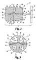
- FIG. 2shows a cross-sectional side view of the spinal implant of FIG. 1 .
- FIG. 3shows a cross-sectional end view of the spinal implant of FIG. 1 .
- FIG. 4 ais an end view of a spinal implant in situ according to the cylindrical form of the present invention.
- FIG. 4 bis a side view of a spinal implant in-situ according to the cylindrical form of the present invention.
- FIG. 5is a cross-sectional end view of another embodiment of the present invention showing an interposed bowl-shaped cap providing impact resistance and wear resistance.
- FIG. 6 ashows a cross-sectional end view of an elliptically-shaped spinal implant of the subject invention.
- FIG. 6 bshows a cross-sectional end view of an alternative elliptically-shaped spinal implant of the subject invention.
- FIG. 7shows a cross-sectional side view of the tapered spinal implant.
- FIG. 8shows a cross-sectional end view of a spinal implant with a rocker and channel articulating means.
- FIG. 9shows a cross-sectional end view of a spinal implant with a hour-glass shaped rocker and a hour-glass shaped channel articulating means.
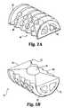
- FIGS. 10 a & 10 bshow a perspective view of a spinal implant with a rocker and channel articulating means.
- FIGS. 11 a & 11 bshow a perspective view of a spinal implant with a rocker and alternative hour-glass channel articulating means.
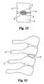
- FIG. 12is an end view of a spinal implant in-situ according to the elliptical form of the present invention.
- FIG. 13is a side view of a spinal implant in-situ according to the tapered form of the present invention.
- FIG. 14 ashows a side view of surgical instrument for cutting an elliptical section in between spinal vertebra.
- FIG. 14 bshows a bottom view of surgical instrument for cutting an elliptical section in between spinal vertebra.
- FIGS. 15 a & 15 bshow a perspective view of a spinal implant with an alternative diamond shaped channel and corresponding diamond shaped rocker articulating means.
- FIG. 16shows a perspective view of a spinal motion segment displaying the Cartesian x, y, and z axes.
- FIG. 17shows a spinal motion segment comprising two adjacent vertebral bodies and an interposed intervertebral disc rotating about an instantaneous axis.
- FIGS. 18 a - 18 cshow an instantaneous axis of rotation below the level of the intervertebral disc of a spinal motion segment in extension/flexion (E, F), right tilt/left tilt (R,L), and right rotation/left rotation (R,L) for various planes.
- FIGS. 19 a - 19 cshow cervical spinal motion segments in flexion, neutral and extension.
- one embodiment of the present inventioncomprises a spinal implant 10 , generally comprising a first element 20 and a second element 22 .
- the first element 20is coupled to the second element 22 by an internal articulation means 24 for allowing relative pivotal movement between the first and second elements.
- FIGS. 4A and 4Bshow the spinal implant 10 of the present invention installed in situ, between a first vertebra 12 and a second vertebra 14 .
- the implant 10is shown implanted into an anterior aspect of the vertebral body, between the fifth cervical and sixth cervical vertebra.
- the device and method of the present inventionare applicable to anterior, lateral, and posterior approaches to the vertebra.
- the first element 20 of the implant 10comprises first connection means, in the form of a first fusion chamber 30 , for engaging the first vertebra 12 .
- At least one opening 32is formed in the first fusion chamber 30 , to facilitate bone growth into, through and around the first fusion chamber 30 from the first vertebra 12 , to fuse the first element to the first vertebra 12 .
- a plurality of openings 32are provided to further promote bone ingrowth. Fusion by bone ingrowth has been found to provide a more permanent, rigid connection between the implant 10 and the skeletal structure, than provided by other known connection means.
- the second element 22 of the implant 10comprises a second connection means for engaging the second vertebra 14 .
- the second connection meanspreferably comprises a second fusion chamber 34 , substantially similar in construction to the above-described first fusion chamber 30 , and comprising at least one opening 36 formed therein for facilitating bone growth into, through, and around the second fusion chamber 34 from the second vertebra 14 .
- the second connection meanscan comprise an adhesive connection, screw connection, pin connection, or any other effective alternative connection means.
- the provision of a second fusion chamber 34is preferred, as it provides a more permanent and secure coupling than other known attachment means.
- first element 20 and first vertebra 12are depicted in the figures as above the second element 22 and second vertebra 14 , it will be understood that the present invention equally comprehends the reverse configuration wherein the first element, as described herein, is attached to a first vertebra lower on the spinal column than the second vertebra to which is attached the second element.
- the first and second elementscan be fabricated from biocompatible materials including, without limitation, titanium, surgical alloys, stainless steel, chrome-molybdenum alloy, cobalt chromium alloy, zirconium oxide ceramic, non-absorbable polymers and other anticipated biocompatible metallic or polymeric materials.
- the articulation means 24 of the present inventionpreferably comprises a first articulation surface 40 provided on the first element 20 , and an abutting second articulation surface 42 provided on the second element 22 .
- the first and second articulation surfaces 40 , 42are preferably fabricated from or coated with low-friction, wear and impact-resistant, biocompatible materials, such as, for example, titanium, stainless steel, surgical alloys, chrome-molybdenum alloys, cobalt chromium alloy, zirconium oxide ceramic, non-absorbable polymers and other biocompatible metallic or polymeric materials.
- the articulation means 24resists axial compression between the first and second elements 20 , 22 , but allows relative pivotal movement there between.
- the articulation means 24resists axial compression between first and second vertebra 12 , 14 along a support axis 44 extending generally along the spinal column, as shown, for example, in FIG. 4, but permits pivotal movement between vertebra.
- the term “pivotal,”is intended to comprehend either or both of a rotational or twisting motion about the support axis 44 (for example, rotation between cervical vertebra by turning the head to the right or left), and/or a tilting motion angularly inclined in any direction relative to the support axis 44 (for example, nodding the head forward or backward and/or tilting the head downward to the right or left).
- axial compressionas well as lateral translation normal to the support axis 44 , is resisted between the first and second vertebra 12 , 14 , by providing the first internal articulation surface 40 with a void, such as a concave surface 46 , which receives a protuberance, such as a convex surface 48 , projecting from the second internal articulation surface 42 .
- This “ball-and-socket” arrangementallows relative rotation about the support axis 44 between the first and second vertebra 12 , 14 .
- the articulation means 24can be provided with one or more stops to limit the range of rotational movement allowed.
- the instantaneous motion of the first and second vertebracan be defined using the instantaneous axis of rotation. At every instant for a rigid body in plane motion, there is a line in the body or a hypothetical extension of this line that does not move. The instantaneous axis of rotation is this line. Plane motion is fully defined by the position of the instantaneous axis of rotation and the magnitude of the rotation about it. The resultant actions of the elementary movements between pairs of adjacent vertebra are the movements of flexion and extension. As shown in FIG.
- the displacement of flexion-extensioncan be described as a circular movement about a transverse axis, where the axis is not situated at the level of the nucleus pulposus but lies below, in the body of the lower vertebra.
- the cartilage-lined articular facetsproduce an articular interface inscribed on the arc of a circle with the same center.
- the superior surface of the discis also inscribed on an arc with the same center.
- the movement of the upper vertebrathus describes an arc with arcuate sliding of the articular facets and pendulous displacement of the disc about the same geometric center, known as the instantaneous axis of rotation.
- the instantaneous motion of a rigid body in three-dimensional spacecan be described as the resultant of the three rotations about the x, y and z axes, as shown in FIG. 16 .
- the centervaries during a given movement and describes an area comprising the instantaneous axis of rotation.
- the location of the instantaneous axis of rotationmay vary according to the region of the spine, for example, in the case of the C 2 -C 3 articulation in the cervical spine, the instantaneous axis of rotation is geometrically lower then other centers in the cervical spine and is found in the body of C 4 .
- the instantaneous axis of rotation of each cervical intervertebral articulationlies in the inferior part of the lower vertebra.
- the instantaneous axis of rotationis located in the central part of the superior surface of the lower vertebra.
- paradoxical motionThis unexpected sliding movement is termed paradoxical motion.
- a functional spinal unitrotates in extension when the overall motion of the segment is in flexion.
- FIG. 19 athe functional spinal unit is in flexion, yet an unexpected ( ⁇ x axis) rotation of the C 5 vertebra occurs, a movement that would be expected if the functional spinal unit were in extension.
- the conversealso occurs with extension.
- FIG. 19 cthe functional spinal unit is in extension and a posterior ( ⁇ z axis) translation is expected, yet the C 5 vertebra displays an anterior (+z axis) translation.
- An objective of the subject inventionis a spinal implant which permits a first vertebra and second vertebra to articulate about an instantaneous axis of rotation and display paradoxical motion, where the articulation of the first vertebra and second vertebra is substantially similar to the physiological motion of a substantially identical pair of adjacent vertebrae interacting with a natural intervertebral disc.
- FIGS. 8, 10 a and 10 bAn example of a spinal implant with an articulating means which permits the first vertebra and second vertebra to articulate about an instantaneous axis of rotation and display paradoxical motion is shown in FIGS. 8, 10 a and 10 b , where the articulating means comprises a rocker 100 and channel 101 .
- the second articulation surface 42can comprise a substantially U-shaped channel 101 extending along the length of the second element 22 .
- the first articulation surface 40comprises a correspondingly shaped rocker 100 which can be, for example, hemi-elliptical in shape along the length of the first element 20 .
- the rocker 100 and channel 101 articulating meanssimulate the physiological spinal articulating conditions of a vertebral disc during flexion and extension by allowing the first and second vertebra to rotate about an instantaneous axis, as shown in FIG. 17, and display paradoxical motion. Additionally, by increasing the number of ranges of motion, the spinal implant can rotate about an instantaneous axis and display paradoxical motion in the frontal and horizontal planes as well. Furthermore, by allowing the first and second vertebra to rotate about an instantaneous axis, the rocker 100 and channel 101 articulating means 24 can decrease the progressive degeneration of adjacent intervertebral discs by decreasing the nonphysiological bio-mechanical stresses and reducing the increase in intradiscal pressures normally associated with vertebral fusion.
- a second range of motioncan be added to the articulating means 24 by modifying the shape of the channel 102 .
- the modified channel 102can be, for example, substantially hour-glass in shape through the depth of the channel 102 .
- the channel width at the channel's base 103 and mouth 104are greater then the channel width at the channel's midpoint 105 .
- the hour-glass shaped channel 102permits a tilting motion along two perpendicular linear planes.
- an alternative second range of motioncan be added to the articulating means 24 by modifying the shape of the channel 101 .
- the modified channel 106can be, for example, substantially hour-glass in shape through the length of the second element 22 .
- the channel width at the channel's longitudinal midpoint 107is less than the channel width at the channel's leading end 108 and tail end 109 .
- the “hour-glass” shape as described hereinincludes various curves or straight edges so long as the width at, or near, the end points of the channel (or the top and bottom of the channel) is wider than the width at some point between the end points.
- the hour-glass shaped channel 106permits two ranges of motion, a tilting motion and a pivoting motion, about the central axis. These motions may be desirable for some patients.
- an alternative second range of motioncan be added to the articulating means 24 by modifying the shape of the channel 101 .
- the modified channel 110can be, for example, substantially diamond in shape through the length of the second element 22 .
- the channel width at the channel's longitudinal midpoint 111is greater than the channel width at the channel's leading end 112 and tail end 113 .
- the first articulation surface 40comprises a correspondingly-shaped rocker 114 which can be, for example, diamond in shape along the length of the first element 20 .
- diamond shape as described hereinincludes various curves or straight edges so long as the width at some point between the end points of the channel (or the top and bottom of the channel) is wider than the width at, or near, the end points.
- the diamond shaped channel 110permits three ranges of motion, a tilting motion and a pivoting motion, about the central axis. These motions may be desirable for some patients.
- the channel's 101 articulating surfacemay be planar, concave or convex, as may be required to duplicate physiologic spinal articulation. It is also noted that the articulating means 24 can be in an opposite configuration as previously disclosed, where the first articulation surface 40 comprises a substantially U-shaped channel 101 extending along the length of the first element 20 , and the second articulation surface 42 comprises a correspondingly-shaped rocker 100 along the length of the second element 22 , where such opposite configuration does not materially affect the function of the subject invention.
- the articulation means 24preferably further comprises one or more angularly offset bevels 50 formed in the first internal articulation surface 40 and/or the second internal articulation surface 42 , to allow relative tilting movement between the first and second vertebra 12 , 14 in one or more directions.
- the first and second internal articulation surfaces 40 , 42are each provided with an angularly offset bevel 50 , in a generally pyramidal configuration, as seen best in FIG. 1, thereby enabling tilting movement in all directions (360°).
- a generally conical configurationis also possible and, likewise, would permit both rotational movement and 360° tilting movement.
- the first and second articulating surfaces 40 , 42can each be provided with a general arc configuration, which provide a greater range of motion.
- the natural range of motion of the spinemay be approximated by providing bevels 50 of approximately 5° around the periphery of each of the first and second articulation surfaces 40 , 42 , thereby allowing approximately 10° of tilt in all directions between adjacent vertebra.
- the pivot point or axis of the articulation means 24is generally centrally located on the first and second articulation surfaces 40 , 42 , and will be aligned with the spine's normal axis of rotation when implanted as shown in FIG. 4 .
- This locationcan be selectively varied to position the center of rotation of the articulation means 24 centrally, anteriorly, posteriorly, to the left, to the right, or eccentrically (off-center in both the anterior/posterior direction and the left/right direction) of the spine's normal axis of rotation, in order to achieve proper alignment of the spine, thereby restoring optimal sagittal and coronal spinal balance and alignment.
- the first and second elements 20 , 22 of the implant 10 of the present inventionpreferably comprise generally hemi-cylindrical outer walls 60 , 70 adjoining to form a generally cylindrical body.
- the first element 20 and the second element 22abut one another with their respective first and second articulating surfaces 40 , 42 adjacent and engaging one another, as described above.
- the first element 20preferably further comprises a first radiused outer wall 60 .
- the one or more openings 32 for facilitating bone ingrowthare provided in this first radiused outer wall 60 , and communicate with a first fusion chamber 62 formed between the first radiused outer wall 60 and the first articulating surface 40 .
- the second element 22preferably comprises a second radiused outer wall 70 , defining one or more openings 36 for facilitating bone ingrowth.
- the openings 36communicate with a second fusion chamber 72 formed between the second radiused outer wall 70 and the second articulating surface 34 .
- the first and second radiused outer walls 60 , 70can be provided with threads 80 to facilitate advancing the implant 10 into the intervertebral space during implantation and to help secure the implant 10 in position once implanted.
- the threads 80 on each of the first and second radiused outer walls 60 , 70are preferably aligned to form continuous threads when the first and second elements 20 , 22 are engaged.
- the threads 80can be replaced with a contoured outer surface comprising smooth, splined, flanged, spiked or beaded surface features.
- the implant 10can further comprise one or more support flanges 85 in the first and/or second elements 20 , 22 , for additional strength.
- the first and second elements 20 , 22 of the implant 10 of the present inventionpreferably comprise hemi-elliptical outer walls 97 , 99 adjoining to form an elliptical body.
- the first element 20 and the second element 22abut one another with their respective first and second articulating surfaces 40 , 42 adjacent and engaging one another, as described above.
- the first element 20preferably further comprises a first radiused outer wall 97 .
- the one or more openings 32 for facilitating bone ingrowthare provided in this first radiused outer wall 97 , and communicate with a first fusion chamber 62 formed between the first radiused outer wall 97 and the first articulating surface 40 .
- the second element 22preferably comprises a second radiused outer wall 99 , defining one or more openings 36 for facilitating bone ingrowth.
- the openings 36communicate with a second fusion chamber 72 formed between the second radiused outer wall 99 and the second articulating surface 42 .
- the contoured outer surfaces of the first and second elements 20 , 22can comprise smooth, splined, flanged, spiked or beaded surface features to secure the element in position once implanted.
- the implant 10can further comprise one or more support flanges 85 in the first and/or second elements 20 , 22 , for additional strength.
- the element 10may be tapered along the horizontal axis.
- the tailing end 92has a vertical radius greater than the vertical radius of the leading end 93 .
- the tapered shapedecreases the amount of material required to be removed and increases the ease of insertion of the implant 10 in between the first and second vertebra.
- the spinal implant 10may have a first and second element for affixing the spinal implant 10 to a first and second vertebra in the shape of a rectangular, plate or any of the affixing means as disclosed in the following: U.S. Pat. No. 4,759, 769, to Hedman, et al., U.S. Pat. No. 4,946,378, to Hirayama, et al., U.S. Pat. No. 4,997,432, to Keller, U.S. Pat. No. 5,002,576, to Fuhrmann, et al., U.S. Pat. No. 5,236,460, to Barber, U.S. Pat. No.
- the present inventionmay further comprise the provision of one or more stabilizing means for temporarily rigidly coupling the first element 20 to the second element 22 to prevent relative movement there between, for example, it is preferred that the first and second elements 20 , 22 be held rigidly in place during installation of the implant 10 into the intervertebral space.
- the first and second elements 20 , 22should remain rigidly coupled for a sufficient length of time after implantation to permit sufficient bone ingrowth into the fusion chambers to prevent relative motion between the implant 10 and the vertebra 12 , 14 during normal activities of the patient. Typically, approximately eight to twenty weeks of bone ingrowth will be sufficient, before the first and second elements 20 , 22 are uncoupled and permitted to articulate relative to one another.
- This temporary stabilization of the first and second elementsis accomplished by the present invention, without the requirement of a second surgical procedure, through the use of medium-term stabilizing means formed from bioreabsorbable material.
- bioreabsorbable materialsinclude polyglycolate polymers or analogues, lactides, polydioxanone, polyglyconate, lactide/glycolide copolymers.
- the stabilizing meanscan comprise one or more biodegradable shims 82 wedged between the first element 20 and the second element 22 , to prevent relative motion there between.
- the first and second elements 20 , 22are placed in their coupled configuration, as shown in FIGS. 2-3, with the spaces between the articulating surfaces 40 , 42 , then being injected or filled with a biodegradable polymer, which provides the medium term temporary stabilizing means to couple the elements in position. Care will be taken to avoid filling the fusion chambers 30 , 34 and the openings 32 , 36 to the fusion chambers with the polymer, which could inhibit bone ingrowth. The threads 80 will also remain exposed to assist in implantation of the device. In another example embodiment, depicted in FIG.
- the stabilizing meanscomprise a removable and/or bioreabsorbable endcap 90 , which releasably engages the tailing end 92 of the implant 10 to couple the first and second elements 20 , 22 .
- the endcapcan comprise one or more clips 94 for engaging the implant 10 , and one or more keyways 96 for engaging a wrench, driver or other actuation device used to advance the implant 10 into the intervertebral space.
- a second removable and/or absorbable endcapcan be installed on the leading end 93 of the implant 10 .
- the endcapsmay additionally function to retain the bone fragments within the chambers 62 , 72 of the fusion chambers 30 , 34 , as will be described in greater detail below, until sufficient bone ingrowth and fusion has occurred.
- FIG. 5shows an implant 10 , generally comprising first and second elements 20 , 22 , substantially as described above, and further comprising an intermediate articulation element, which in the depicted embodiment comprises a generally hemispherical bowl-shaped cap 90 interposed between the concave surface 46 of the first element 20 and the convex surface 48 of the second element 22 .
- the cap 90is preferably fabricated from a wear-resistant, low friction material of construction, which may be somewhat resilient to absorb impact loading.
- the provision of the cap 90allows articulation at the interface between the top surface of the cap and the concave surface 46 of the first element 20 , and between the bottom surface of the cap and the convex surface 48 of the second element 22 , resulting in a bipolar articulation.
- This arrangementreduces frictional wear on the articulation surfaces by distributing wear over two articulation interfaces.
- the engagement of the concave lower surface of the cap 90 with the convex surface 48 of the second element 22 , and the engagement of the convex upper surface of the cap 90 with the concave surface 46 of the first element 20prevents the cap 90 from becoming dislodged when the implant 10 is installed.
- the present inventionfurther comprises a method of maintaining a desired intervertebral space between a first vertebra 12 and a second vertebra 14 .
- the methodpreferably comprises removing a section of the first vertebra to form a cavity therein, mounting a first element of an articulating spinal implant into the cavity, and connecting a second element of the implant to the second vertebra.
- the articulating spinal implant used to carry out this methodis preferably substantially similar to the example embodiment described above, having first and second internal articulation surfaces which adjoin to form a joint allowing relative pivotal movement between the first and second elements, but preventing relative axial compression there between.
- At least one of the elementspreferably further comprises a fusion chamber, including a chamber and at least one opening communicating with the chamber, for facilitating bone ingrowth into, through, and around the fusion chamber from the respective vertebra.
- the method of the present inventioncomprises attachments of both the first and second elements of the implant to the respective vertebra using fusion chambers for bone ingrowth.
- a section of the second vertebrais preferably removed to form a cavity therein for receiving the second element of the implant.
- the method of the present inventioncan further comprise the insertion of bone fragments, which may be the fragments formed in the above-described removal of vertebral sections, into the fusion chamber(s) of the implant.
- the method of the present inventionanticipates the application of means for stimulating bone growth into, through, and/or around the fusion chamber(s).
- the means for stimulating bone growthcan comprise, for example, electrical or magnetic bone growth stimulators, bone morphogenetic protein (BMP), hydroxyl apatite compounds, demineralized bone compound, and/or other bone growth stimulating devices or compounds.
- BMPbone morphogenetic protein
- hydroxyl apatite compoundshydroxyl apatite compounds
- demineralized bone compounddemineralized bone compound
- other bone growth stimulating devices or compoundsfor example, electrical or magnetic bone growth stimulators, bone morphogenetic protein (BMP), hydroxyl apatite compounds, demineralized bone compound, and/or other bone growth stimulating devices or compounds.
- BMPbone morphogenetic protein
- hydroxyl apatite compoundsdemineralized bone compound
- demineralized bone compounddemineralized bone compound
- Implantation of the articulating spinal implantmay be carried out in a manner generally similar to previously-known methods for the implantation of non-articulating, rigid-fusion implants, with exceptions as set out herein, for example, the method of the present invention may utilize standard surgical approaches to the spine from either an anterior approach for the cervical and thoracic spinal segments, or from an anterior or posterior lateral approach to the lumbar spinal segments.
- the removal of vertebral sectionsmay be accomplished by drilling or chipping a generally circular bore having a diameter and depth adapted to generally match the implant to be utilized, bridging the first and second vertebra. Additionally, the circular bore may be tapered with the leading end diameter being smaller then the tail end diameter.
- the boreis preferably centered over the intervertebral space, approximately midway between the first and second vertebra. Threads may then be tapped into the bore to facilitate insertion of the implant.
- the removal of vertebral sectionsmay be accomplished by using an unique surgical instrument, as shown in FIGS. 14 a and 14 b , for drilling an elliptical bore having a major and minor diameter and depth adapted to generally match the implant to be utilized, bridging the first and second vertebra.
- the surgical instrumentis affixed to a drill to provide rotational power to the cutting portion.
- the cutting portion of the surgical instrumentconsists of a circular flute drill bit sheathed within cutting blades formed in an elliptical shape. The flute drill bit extends out beyond cutting blades to cut a circular section between the first and second vertebra. As the drill bit cuts into the vertebra, the cutting blades then remove the remaining material to form an elliptical bore having a major and minor diameter and depth adapted to generally match the implant to be utilized, bridging the first and second vertebra.
- the implantcan be provided with self-tapping threads.
- the implantis assembled with the first and second articulating surfaces engaged, and the first and second elements of the implant are rigidly coupled by stabilizing means substantially as described above.
- the stabilized implantis advanced into the bore to the desired depth.
- the implantis advanced until the tailing end 92 is flush or slightly recessed relative to the outer surface of the vertebra, thereby eliminating the possibility that outwardly projecting portions of the implant may interfere with or injure adjacent or regional vascular, neural or visceral structures.
- two articulating implantscan be placed in parallel positions with the lengthwise axis of each adjacent one to the other, in a generally parallel arrangement, allowing flexion/extension movement alone.
- This arrangementwill typically require removal of vertebral material to form two openings, or an extended opening to accommodate both implants.
- a single, appropriately sized implantcould be placed in the interspace utilizing the transabdominal open surgical approach, the transabdominal laparoscopic approach, or the retroperitoneal open anterior approach allowing pivotal motion around the single point of articulation as described above for use in cervical and thoracic intervertebral disc spaces.
- the stabilizing meansis dissolved and absorbed into the body, uncoupling the articulation means to permit relative motion between the first and second elements, thus preserving spinal flexibility and minimizing destructive stress upon adjacent intervertebral joints.
- the implantresists axial compression between the first and second elements, thereby preventing relative compression between the first and second vertebra, thus maintaining the desired intervertebral space. Further, the implant is recessed into the recipient vertebral site, eliminating impingement on the next adjacent vascular, neural or visceral structures.
Landscapes
- Health & Medical Sciences (AREA)
- Engineering & Computer Science (AREA)
- Biomedical Technology (AREA)
- Orthopedic Medicine & Surgery (AREA)
- Neurology (AREA)
- Life Sciences & Earth Sciences (AREA)
- General Health & Medical Sciences (AREA)
- Oral & Maxillofacial Surgery (AREA)
- Veterinary Medicine (AREA)
- Heart & Thoracic Surgery (AREA)
- Public Health (AREA)
- Animal Behavior & Ethology (AREA)
- Cardiology (AREA)
- Vascular Medicine (AREA)
- Transplantation (AREA)
- Surgery (AREA)
- Dentistry (AREA)
- Nuclear Medicine, Radiotherapy & Molecular Imaging (AREA)
- Medical Informatics (AREA)
- Molecular Biology (AREA)
- Prostheses (AREA)
Abstract
Description
This application is a continuation-in-part of patent application Ser. No. 09/389,758, filed Sep. 2, 1999, now U.S. Pat. No. 6,440,168, which is a continuation-in-part of patent application Ser. No. 09/298,524, filed Apr. 23, 1999, now U.S. Pat. No. 6,179,874, which is a continuation-in-part of patent application Ser. No. 09/065,816, filed Apr. 23, 1998, now issued on Feb. 1, 2000 as U.S. Pat. No. 6,019,792.
1. Field of the Invention
The invention relates generally to spinal implants for use in intervertebral disc replacement; and more specifically relates to articulating implants that fuse to adjacent vertebra by bone ingrowth, thus restoring proper intervertebral spacing, and eliminating nerve root and/or spinal cord compression, while preserving spinal flexibility.
2. Description of Related Art
The spinal column is formed from a number of vertebra, which in their normal state are separated from one another by cartilaginous intervertebral discs. These discs form a cushion between adjacent vertebra, resisting compression along the support axis of the spinal column, but permitting limited movement between the vertebra to provide the characteristic flexibility of the healthy spine. Injury, disease or other degenerative disorders may cause one or more intervertebral discs to shrink, collapse, deteriorate or become displaced, herniated, or otherwise damaged. This can lead to compression of adjacent nerve root(s) or the spinal cord causing chronic and often disabling pain, and in advanced circumstances, irreversible paralysis of upper and/or lower limbs.
A number of devices and methods have been suggested for the replacement of damaged or dislocated intervertebral discs. One common approach is to permanently stabilize or “fuse” the adjacent vertebra to maintain the proper intervertebral spacing and eliminate relative movement between the vertebra. Various methods of vertebral stabilization have been developed, for example, autogenous grafts of dowel-shaped sections of bone have been implanted between the vertebra to cause bone growth across the intervertebral space, thereby fusing the adjacent vertebra into one bone mass. This procedure disadvantageously requires the harvest of donor bone for the graft from other parts of the patient's body, typically requiring a separate surgical procedure and resultant increases in complications and expense. An alternative source is cadaver bone, with potential complications of transmissible diseases, impaired graft incorporation, collapse or displacement. A further development to this method of vertebral stabilization involves the implantation of a perforated cylindrical bone basket between adjacent vertebra. Bone fragments produced in preparing the vertebra for the implantation are inserted into the bone basket to promote bone growth into, through, and around the basket.
Vertebral stabilization by fusion of adjacent vertebra has proven successful in permanently preserving intervertebral spacing, but has been found to present a number of disadvantages. Fusion of adjacent vertebra necessarily eliminates a portion of the spine's normal range of motion, thereby reducing the subject's spinal flexibility. Additionally, long-term investigations after fusion of the vertebra have revealed deterioration in the next adjacent segments, ranging from increasing osteophyte formation, to collapse of the intervertebral disc, implicating progressive degeneration of the afflicted motion segment, resulting in hyper- and/or hypomobility of the segment. It is believed that fusion results in nonphysiological bio-mechanical stress of the adjacent segment. In addition to the nonphysiological bio-mechanical stress, there is an increase in the intradiscal pressure (PID) on the adjacent intervertebral disc. Changes in the PID may impair the nutrition of the intervertebral disc, which can lead to increased degeneration and pain in any plane of motion and/or compression of the spinal cord on spinal nerves.
It has also been proposed to replace an injured intervertebral disc with a prosthesis which is “jointed” to permit relative movement between vertebra. Previously known devices of this type generally have been found to suffer from inadequate attachment between the prosthesis and the vertebra. The intended movement between the components of previously known jointed prostheses can cause relative motion between the prosthesis and the adjacent bone surface(s). Because such motion would disrupt bone ingrowth, jointed prostheses have generally been considered incompatible with attachment by bone ingrowth. In addition, because the joint elements of these devices typically must occupy a substantial vertical extent in order to achieve the desired range of motion, and yet must fit within the intervertebral space, attachment of such devices generally has been by use of flat plates or surfaces provided on either side of the joint elements as points of fixation to the vertebra. This attachment may be accomplished by compressive or friction fits, spiked projections, screws or pins, complemented in some instances with tissue ingrowth into porous surfaces. These mechanisms of attachment, however, may lack the degree and strength of fixation desired. Moreover, several such devices have used attachment flanges which extend beyond the surfaces of the vertebra to which the device is attached. This has been found undesirable, as the extending flanges may interfere with or injure adjacent tissue; for example, it has been reported that flanges extending into immediately adjacent delicate esophageal areas may interfere with swallowing and speech, or cause perforation and potentially fatal infection. An additional drawback to the use of screw and pin connections is the potential for such connectors to dislodge and cause injury. Examples of such prosthetic implants are disclosed in the following: U.S. Pat. No. 4,759,769, to Hedman et al., U.S. Pat. No. 4,946,378, to Hirayama et al., U.S. Pat. No. 4,997,432, to Keller, U.S. Pat. No. 5,002,576, to Fuhrmann et al., U.S. Pat. No. 5,236,460, to Barber, U.S. Pat. No. 5,258,031, to Salib et al., U.S. Pat. No. 5,306,308, to Gross, et al., U.S. Pat. No. 5,401,269, to Buttner-Janz, et al., U.S. Pat. No. 5,425,773, to Boyd, et al. and U.S. Pat. No. 5,782,832, to Larsen, et al.
Thus, it can be seen that a need yet exists for a spinal implant effective in permanently maintaining intervertebral spacing to prevent nerve or spinal cord compression, while preserving as much of the natural range of motion between the affected vertebra as possible. A need further exists for such a device which is capable of forming a permanent, strong attachment to the vertebra, yet does not protrude beyond the external surfaces to which it is attached. Still another need exists for a method of replacing a damaged or displaced disc, maintaining intervertebral spacing to prevent nerve and spinal cord compression, while preserving the natural relative motion between the vertebra. It is to the provision of devices and methods meeting these and other needs that the present invention is primarily directed.
Briefly described, in a preferred form, the present invention comprises a spinal implant including a first element having first connection means for engaging a first vertebra. The first connection means includes a first fusion chamber having at least one opening therein for facilitating bone ingrowth into the first fusion chamber to fuse the first element to the first vertebra. The implant also includes a second element having second connection means for engaging a second vertebra. The second connection means includes a second fusion chamber having at least one opening therein for facilitating bone ingrowth into the second fusion chamber to fuse the second element to the second vertebra. The implant also includes internal articulation means, coupling the first element to the second element, for allowing relative movement between the first element and the second element. As used herein, the term “internal articulation means,” refers to a means for facilitating relative motion between components of the implant, rather than between the implant and an external structure such as adjacent bone or other tissue.
In specific embodiments of the subject invention, the first and second elements may have either hemi-cylindrical or hemi-elliptical shaped outer surfaces. The first and second elements each having an outer wall perforated with one or more openings provided therein to allow bone ingrowth into the fusion chambers, and having abutting joint surfaces forming the internal articulation means. In a further preferred embodiment, the joint surfaces are formed as engaging concave and convex surfaces to create a ball-and-socket type joint (or rocker and channel, or other such joint), which allows relative pivotal motion between the vertebra, but resists compression there between.
The first and second elements can join to form a single element which can be implanted using methods similar to those followed in the implantation of previously known non-articulating vertebral fusion implants. Temporary stabilizing means can be provided for rigidly coupling the first and second elements by interposition of bioreabsorbable elements to permit implantation and enable bone ingrowth into the fusion chambers and fusion of the first and second elements to adjacent bone during an initial stabilization period, after which said temporary means biodegrades permitting articulation between the first and second elements.
The present invention can be further described as comprising a spinal implant having a first articulation surface, a second articulation surface engaging at least a portion of the first articulation surface along a support axis generally parallel to the spinal column, first connection means for connecting the first articulation surface to a first vertebra, and second connection means for connecting the second articulation surface to a second vertebra. The first and second articulation surfaces resist axial compression between the first and second elements in the direction of the support axis, but allows relative pivotal motion between the first and second elements. At least one, and preferably both, of the first connection means and the second connection means comprise a fusion chamber having at least one opening therein for facilitating bone ingrowth, thereby permanently and securely affixing the implant in place.
In another preferred form, the present invention comprises a method of maintaining an intervertebral space between a first vertebra and a second vertebra. The method includes the steps of removing a section of the first vertebra to form a cavity therein, mounting a first element of a spinal implant within the cavity formed in the first vertebra, and connecting a second element of the spinal implant to the second vertebra. The first element includes a first articulation surface and a first fusion chamber having at least one opening therein for facilitating bone ingrowth from the first vertebra. The second element includes a second articulation surface, wherein the first and second articulation surfaces adjoin to form a joint allowing relative pivotal movement between the first and second elements but preventing relative compression between the first and second elements. In a further preferred embodiment, the method may also include the removal of a section of the second vertebra to form a cavity for receiving the second element. The second element may also include a second fusion chamber for facilitating bone ingrowth from the second vertebra. Bone fragments formed by the removal of vertebral sections to accommodate implantation or bone growth stimulating compounds or devices may be inserted into the fusion chamber(s) to enhance bone ingrowth.
These and other objects, features and advantages of the present invention, will be more readily understood with reference to the following detailed description, read in conjunction with the accompanying figures. All patents, patent applications and publications referred to or cited herein, or from which a claim for benefit of priority has been made, are incorporated by reference in their entirety to the extent they are not inconsistent with the explicit teachings of this specification.
FIGS. 1a&1bshows a perspective view of a spinal implant according to one cylindrical form of the present invention.
FIG. 2 shows a cross-sectional side view of the spinal implant of FIG.1.
FIG. 3 shows a cross-sectional end view of the spinal implant of FIG.1.
FIG. 4ais an end view of a spinal implant in situ according to the cylindrical form of the present invention.
FIG. 4bis a side view of a spinal implant in-situ according to the cylindrical form of the present invention.
FIG. 5 is a cross-sectional end view of another embodiment of the present invention showing an interposed bowl-shaped cap providing impact resistance and wear resistance.
FIG. 6ashows a cross-sectional end view of an elliptically-shaped spinal implant of the subject invention.
FIG. 6bshows a cross-sectional end view of an alternative elliptically-shaped spinal implant of the subject invention.
FIG. 7 shows a cross-sectional side view of the tapered spinal implant.
FIG. 8 shows a cross-sectional end view of a spinal implant with a rocker and channel articulating means.
FIG. 9 shows a cross-sectional end view of a spinal implant with a hour-glass shaped rocker and a hour-glass shaped channel articulating means.
FIGS. 10a&10bshow a perspective view of a spinal implant with a rocker and channel articulating means.
FIGS. 11a&11bshow a perspective view of a spinal implant with a rocker and alternative hour-glass channel articulating means.
FIG. 12 is an end view of a spinal implant in-situ according to the elliptical form of the present invention.
FIG. 13 is a side view of a spinal implant in-situ according to the tapered form of the present invention.
FIG. 14ashows a side view of surgical instrument for cutting an elliptical section in between spinal vertebra.
FIG. 14bshows a bottom view of surgical instrument for cutting an elliptical section in between spinal vertebra.
FIGS. 15a&15bshow a perspective view of a spinal implant with an alternative diamond shaped channel and corresponding diamond shaped rocker articulating means.
FIG. 16 shows a perspective view of a spinal motion segment displaying the Cartesian x, y, and z axes.
FIG. 17 shows a spinal motion segment comprising two adjacent vertebral bodies and an interposed intervertebral disc rotating about an instantaneous axis.
FIGS. 18a-18cshow an instantaneous axis of rotation below the level of the intervertebral disc of a spinal motion segment in extension/flexion (E, F), right tilt/left tilt (R,L), and right rotation/left rotation (R,L) for various planes.
FIGS. 19a-19cshow cervical spinal motion segments in flexion, neutral and extension.
Referring now in detail to the figures, wherein like reference numbers represent like parts throughout, preferred forms of the present invention will now be described. As seen in FIGS. 1-3, one embodiment of the present invention comprises aspinal implant 10, generally comprising afirst element 20 and asecond element 22. Thefirst element 20 is coupled to thesecond element 22 by an internal articulation means24 for allowing relative pivotal movement between the first and second elements.
FIGS. 4A and 4B show thespinal implant 10 of the present invention installed in situ, between afirst vertebra 12 and asecond vertebra 14. Theimplant 10 is shown implanted into an anterior aspect of the vertebral body, between the fifth cervical and sixth cervical vertebra. The device and method of the present invention, however, are applicable to anterior, lateral, and posterior approaches to the vertebra.
As seen best in FIGS. 2-3, thefirst element 20 of theimplant 10 comprises first connection means, in the form of afirst fusion chamber 30, for engaging thefirst vertebra 12. At least oneopening 32 is formed in thefirst fusion chamber 30, to facilitate bone growth into, through and around thefirst fusion chamber 30 from thefirst vertebra 12, to fuse the first element to thefirst vertebra 12. Preferably, a plurality ofopenings 32 are provided to further promote bone ingrowth. Fusion by bone ingrowth has been found to provide a more permanent, rigid connection between theimplant 10 and the skeletal structure, than provided by other known connection means.
Thesecond element 22 of theimplant 10 comprises a second connection means for engaging thesecond vertebra 14. The second connection means preferably comprises asecond fusion chamber 34, substantially similar in construction to the above-describedfirst fusion chamber 30, and comprising at least oneopening 36 formed therein for facilitating bone growth into, through, and around thesecond fusion chamber 34 from thesecond vertebra 14. Alternatively, the second connection means can comprise an adhesive connection, screw connection, pin connection, or any other effective alternative connection means. However, the provision of asecond fusion chamber 34 is preferred, as it provides a more permanent and secure coupling than other known attachment means. Although thefirst element 20 andfirst vertebra 12 are depicted in the figures as above thesecond element 22 andsecond vertebra 14, it will be understood that the present invention equally comprehends the reverse configuration wherein the first element, as described herein, is attached to a first vertebra lower on the spinal column than the second vertebra to which is attached the second element. The first and second elements can be fabricated from biocompatible materials including, without limitation, titanium, surgical alloys, stainless steel, chrome-molybdenum alloy, cobalt chromium alloy, zirconium oxide ceramic, non-absorbable polymers and other anticipated biocompatible metallic or polymeric materials.
Referring now to FIGS. 2-3, the articulation means24 of the present invention preferably comprises afirst articulation surface 40 provided on thefirst element 20, and an abuttingsecond articulation surface 42 provided on thesecond element 22. The first and second articulation surfaces40,42 are preferably fabricated from or coated with low-friction, wear and impact-resistant, biocompatible materials, such as, for example, titanium, stainless steel, surgical alloys, chrome-molybdenum alloys, cobalt chromium alloy, zirconium oxide ceramic, non-absorbable polymers and other biocompatible metallic or polymeric materials. The articulation means24 resists axial compression between the first andsecond elements second vertebra support axis 44 extending generally along the spinal column, as shown, for example, in FIG. 4, but permits pivotal movement between vertebra. The term “pivotal,” is intended to comprehend either or both of a rotational or twisting motion about the support axis44 (for example, rotation between cervical vertebra by turning the head to the right or left), and/or a tilting motion angularly inclined in any direction relative to the support axis44 (for example, nodding the head forward or backward and/or tilting the head downward to the right or left).
In a preferred embodiment, axial compression, as well as lateral translation normal to thesupport axis 44, is resisted between the first andsecond vertebra internal articulation surface 40 with a void, such as aconcave surface 46, which receives a protuberance, such as aconvex surface 48, projecting from the secondinternal articulation surface 42. This “ball-and-socket” arrangement allows relative rotation about thesupport axis 44 between the first andsecond vertebra
In addition to the “ball-and socket” arrangement for the articulatingmeans 24, other configurations are possible which more closely follow the bio-mechanical motions of the first and second vertebra. The instantaneous motion of the first and second vertebra can be defined using the instantaneous axis of rotation. At every instant for a rigid body in plane motion, there is a line in the body or a hypothetical extension of this line that does not move. The instantaneous axis of rotation is this line. Plane motion is fully defined by the position of the instantaneous axis of rotation and the magnitude of the rotation about it. The resultant actions of the elementary movements between pairs of adjacent vertebra are the movements of flexion and extension. As shown in FIG. 17, the displacement of flexion-extension can be described as a circular movement about a transverse axis, where the axis is not situated at the level of the nucleus pulposus but lies below, in the body of the lower vertebra. The cartilage-lined articular facets produce an articular interface inscribed on the arc of a circle with the same center. The superior surface of the disc is also inscribed on an arc with the same center. The movement of the upper vertebra thus describes an arc with arcuate sliding of the articular facets and pendulous displacement of the disc about the same geometric center, known as the instantaneous axis of rotation. The instantaneous motion of a rigid body in three-dimensional space can be described as the resultant of the three rotations about the x, y and z axes, as shown in FIG.16. As shown in FIGS. 18a-18c, the center varies during a given movement and describes an area comprising the instantaneous axis of rotation.
The location of the instantaneous axis of rotation may vary according to the region of the spine, for example, in the case of the C2-C3 articulation in the cervical spine, the instantaneous axis of rotation is geometrically lower then other centers in the cervical spine and is found in the body of C4. Below the C2-C3 intervertebral joint, the instantaneous axis of rotation of each cervical intervertebral articulation lies in the inferior part of the lower vertebra. In the thoracic and lumbar regions, the instantaneous axis of rotation is located in the central part of the superior surface of the lower vertebra. One consequence of this lower position of the instantaneous axis or rotation in flexion/extension is the anterior sliding or anterolisthesis of one superior or upper vertebra in the subjacent vertebra during extension.
This unexpected sliding movement is termed paradoxical motion. In paradoxical motion a functional spinal unit rotates in extension when the overall motion of the segment is in flexion. As shown in FIG. 19a, the functional spinal unit is in flexion, yet an unexpected (−x axis) rotation of the C5 vertebra occurs, a movement that would be expected if the functional spinal unit were in extension. The converse also occurs with extension. As shown in FIG. 19c, the functional spinal unit is in extension and a posterior (−z axis) translation is expected, yet the C5 vertebra displays an anterior (+z axis) translation. These paradoxical motions are described in the sagittal plane; they could also occur in the frontal and horizontal planes as well. An objective of the subject invention is a spinal implant which permits a first vertebra and second vertebra to articulate about an instantaneous axis of rotation and display paradoxical motion, where the articulation of the first vertebra and second vertebra is substantially similar to the physiological motion of a substantially identical pair of adjacent vertebrae interacting with a natural intervertebral disc.
An example of a spinal implant with an articulating means which permits the first vertebra and second vertebra to articulate about an instantaneous axis of rotation and display paradoxical motion is shown in FIGS. 8,10aand10b, where the articulating means comprises arocker 100 andchannel 101. Thesecond articulation surface 42 can comprise a substantiallyU-shaped channel 101 extending along the length of thesecond element 22. Thefirst articulation surface 40 comprises a correspondingly shapedrocker 100 which can be, for example, hemi-elliptical in shape along the length of thefirst element 20. Therocker 100 andchannel 101 articulating means simulate the physiological spinal articulating conditions of a vertebral disc during flexion and extension by allowing the first and second vertebra to rotate about an instantaneous axis, as shown in FIG. 17, and display paradoxical motion. Additionally, by increasing the number of ranges of motion, the spinal implant can rotate about an instantaneous axis and display paradoxical motion in the frontal and horizontal planes as well. Furthermore, by allowing the first and second vertebra to rotate about an instantaneous axis, therocker 100 andchannel 101 articulatingmeans 24 can decrease the progressive degeneration of adjacent intervertebral discs by decreasing the nonphysiological bio-mechanical stresses and reducing the increase in intradiscal pressures normally associated with vertebral fusion.
In an alternative to this embodiment, as shown in FIG. 9, a second range of motion can be added to the articulatingmeans 24 by modifying the shape of thechannel 102. The modifiedchannel 102 can be, for example, substantially hour-glass in shape through the depth of thechannel 102. The channel width at the channel'sbase 103 andmouth 104 are greater then the channel width at the channel'smidpoint 105. The hour-glass shapedchannel 102 permits a tilting motion along two perpendicular linear planes.
In a second alternative to this embodiment, as shown in FIGS. 11aand11b, an alternative second range of motion can be added to the articulatingmeans 24 by modifying the shape of thechannel 101. The modifiedchannel 106 can be, for example, substantially hour-glass in shape through the length of thesecond element 22. The channel width at the channel'slongitudinal midpoint 107 is less than the channel width at the channel'sleading end 108 andtail end 109. Those skilled in the art, having the benefit of the instant disclosure, will appreciate that the “hour-glass” shape as described herein includes various curves or straight edges so long as the width at, or near, the end points of the channel (or the top and bottom of the channel) is wider than the width at some point between the end points. The hour-glass shapedchannel 106 permits two ranges of motion, a tilting motion and a pivoting motion, about the central axis. These motions may be desirable for some patients.
In a third alternative to this embodiment, as shown in FIGS. 15aand15b, an alternative second range of motion can be added to the articulatingmeans 24 by modifying the shape of thechannel 101. The modifiedchannel 110 can be, for example, substantially diamond in shape through the length of thesecond element 22. The channel width at the channel'slongitudinal midpoint 111 is greater than the channel width at the channel'sleading end 112 andtail end 113. Additionally, thefirst articulation surface 40 comprises a correspondingly-shapedrocker 114 which can be, for example, diamond in shape along the length of thefirst element 20. Those skilled in the art, having the benefit of the instant disclosure, will appreciate that the “diamond” shape as described herein includes various curves or straight edges so long as the width at some point between the end points of the channel (or the top and bottom of the channel) is wider than the width at, or near, the end points. The diamond shapedchannel 110 permits three ranges of motion, a tilting motion and a pivoting motion, about the central axis. These motions may be desirable for some patients.
The channel's101 articulating surface may be planar, concave or convex, as may be required to duplicate physiologic spinal articulation. It is also noted that the articulating means24 can be in an opposite configuration as previously disclosed, where thefirst articulation surface 40 comprises a substantiallyU-shaped channel 101 extending along the length of thefirst element 20, and thesecond articulation surface 42 comprises a correspondingly-shapedrocker 100 along the length of thesecond element 22, where such opposite configuration does not materially affect the function of the subject invention.
The articulation means24 preferably further comprises one or more angularly offsetbevels 50 formed in the firstinternal articulation surface 40 and/or the secondinternal articulation surface 42, to allow relative tilting movement between the first andsecond vertebra bevel 50, in a generally pyramidal configuration, as seen best in FIG. 1, thereby enabling tilting movement in all directions (360°). A generally conical configuration is also possible and, likewise, would permit both rotational movement and 360° tilting movement. Additionally, as shown in FIGS. 10 and 11, the first and second articulatingsurfaces
The natural range of motion of the spine may be approximated by providingbevels 50 of approximately 5° around the periphery of each of the first and second articulation surfaces40,42, thereby allowing approximately 10° of tilt in all directions between adjacent vertebra. As depicted in the figures, the pivot point or axis of the articulation means24 is generally centrally located on the first and second articulation surfaces40,42, and will be aligned with the spine's normal axis of rotation when implanted as shown in FIG.4. This location, however, can be selectively varied to position the center of rotation of the articulation means24 centrally, anteriorly, posteriorly, to the left, to the right, or eccentrically (off-center in both the anterior/posterior direction and the left/right direction) of the spine's normal axis of rotation, in order to achieve proper alignment of the spine, thereby restoring optimal sagittal and coronal spinal balance and alignment.
In one embodiment as shown best by FIGS. 1-3, the first andsecond elements implant 10 of the present invention, preferably comprise generally hemi-cylindricalouter walls first element 20 and thesecond element 22 abut one another with their respective first and second articulatingsurfaces first element 20 preferably further comprises a first radiusedouter wall 60. The one ormore openings 32 for facilitating bone ingrowth are provided in this first radiusedouter wall 60, and communicate with afirst fusion chamber 62 formed between the first radiusedouter wall 60 and the first articulatingsurface 40. Similarly, thesecond element 22 preferably comprises a second radiusedouter wall 70, defining one ormore openings 36 for facilitating bone ingrowth. Theopenings 36 communicate with asecond fusion chamber 72 formed between the second radiusedouter wall 70 and the second articulatingsurface 34. The first and second radiusedouter walls threads 80 to facilitate advancing theimplant 10 into the intervertebral space during implantation and to help secure theimplant 10 in position once implanted. Thethreads 80 on each of the first and second radiusedouter walls second elements threads 80, and/or to configure thethreads 80 to direct bone fragments generated by implantation into theopenings 32, as taught by U.S. Pat. No. 5,489,308 to Kuslich, et al. In other less preferred embodiments, thethreads 80 can be replaced with a contoured outer surface comprising smooth, splined, flanged, spiked or beaded surface features. Theimplant 10 can further comprise one ormore support flanges 85 in the first and/orsecond elements
In a second embodiment as shown best by FIGS. 6a,6band12, the first andsecond elements implant 10 of the present invention preferably comprise hemi-ellipticalouter walls first element 20 and thesecond element 22 abut one another with their respective first and second articulatingsurfaces first element 20 preferably further comprises a first radiusedouter wall 97. The one ormore openings 32 for facilitating bone ingrowth are provided in this first radiusedouter wall 97, and communicate with afirst fusion chamber 62 formed between the first radiusedouter wall 97 and the first articulatingsurface 40. Similarly, thesecond element 22 preferably comprises a second radiusedouter wall 99, defining one ormore openings 36 for facilitating bone ingrowth. Theopenings 36 communicate with asecond fusion chamber 72 formed between the second radiusedouter wall 99 and the second articulatingsurface 42. In alternative embodiments the contoured outer surfaces of the first andsecond elements implant 10 can further comprise one ormore support flanges 85 in the first and/orsecond elements
In another embodiment, as shown in FIGS. 7 and 13, theelement 10 may be tapered along the horizontal axis. The tailingend 92 has a vertical radius greater than the vertical radius of theleading end 93. The tapered shape decreases the amount of material required to be removed and increases the ease of insertion of theimplant 10 in between the first and second vertebra.
In still further embodiments, thespinal implant 10 may have a first and second element for affixing thespinal implant 10 to a first and second vertebra in the shape of a rectangular, plate or any of the affixing means as disclosed in the following: U.S. Pat. No. 4,759, 769, to Hedman, et al., U.S. Pat. No. 4,946,378, to Hirayama, et al., U.S. Pat. No. 4,997,432, to Keller, U.S. Pat. No. 5,002,576, to Fuhrmann, et al., U.S. Pat. No. 5,236,460, to Barber, U.S. Pat. No. 5,258,031, to Salib, et al., U.S. Pat. No. 5,306,308, to Gross, et al., U.S. Pat. No. 5,401,269, to Buttner-Janz, et al., U.S. Pat. No. 5,425,773, to Boyd, et al., and U.S. Pat. No. 5,782,832, to Larsen, et al.
In a further preferred embodiment. As shown in FIGS. 2-3, the present invention may further comprise the provision of one or more stabilizing means for temporarily rigidly coupling thefirst element 20 to thesecond element 22 to prevent relative movement there between, for example, it is preferred that the first andsecond elements implant 10 into the intervertebral space. In addition, the first andsecond elements implant 10 and thevertebra second elements implant 10 are uncoupled, allowing articulation. In one example embodiment, depicted in FIG. 3, the stabilizing means can comprise one or morebiodegradable shims 82 wedged between thefirst element 20 and thesecond element 22, to prevent relative motion there between. In another example embodiment, the first andsecond elements surfaces fusion chambers openings threads 80 will also remain exposed to assist in implantation of the device. In another example embodiment, depicted in FIG. 2, the stabilizing means comprise a removable and/orbioreabsorbable endcap 90, which releasably engages the tailingend 92 of theimplant 10 to couple the first andsecond elements more clips 94 for engaging theimplant 10, and one ormore keyways 96 for engaging a wrench, driver or other actuation device used to advance theimplant 10 into the intervertebral space. A second removable and/or absorbable endcap can be installed on the leadingend 93 of theimplant 10. The endcaps may additionally function to retain the bone fragments within thechambers fusion chambers
Another embodiment of the present invention is depicted by FIG. 5, which shows animplant 10, generally comprising first andsecond elements cap 90 interposed between theconcave surface 46 of thefirst element 20 and theconvex surface 48 of thesecond element 22. Thecap 90 is preferably fabricated from a wear-resistant, low friction material of construction, which may be somewhat resilient to absorb impact loading. The provision of thecap 90 allows articulation at the interface between the top surface of the cap and theconcave surface 46 of thefirst element 20, and between the bottom surface of the cap and theconvex surface 48 of thesecond element 22, resulting in a bipolar articulation. This arrangement reduces frictional wear on the articulation surfaces by distributing wear over two articulation interfaces. The engagement of the concave lower surface of thecap 90 with theconvex surface 48 of thesecond element 22, and the engagement of the convex upper surface of thecap 90 with theconcave surface 46 of thefirst element 20, prevents thecap 90 from becoming dislodged when theimplant 10 is installed.
The present invention further comprises a method of maintaining a desired intervertebral space between afirst vertebra 12 and asecond vertebra 14. The method preferably comprises removing a section of the first vertebra to form a cavity therein, mounting a first element of an articulating spinal implant into the cavity, and connecting a second element of the implant to the second vertebra. The articulating spinal implant used to carry out this method is preferably substantially similar to the example embodiment described above, having first and second internal articulation surfaces which adjoin to form a joint allowing relative pivotal movement between the first and second elements, but preventing relative axial compression there between. At least one of the elements preferably further comprises a fusion chamber, including a chamber and at least one opening communicating with the chamber, for facilitating bone ingrowth into, through, and around the fusion chamber from the respective vertebra. In a preferred form, the method of the present invention comprises attachments of both the first and second elements of the implant to the respective vertebra using fusion chambers for bone ingrowth. In this embodiment, a section of the second vertebra is preferably removed to form a cavity therein for receiving the second element of the implant. The method of the present invention can further comprise the insertion of bone fragments, which may be the fragments formed in the above-described removal of vertebral sections, into the fusion chamber(s) of the implant. The presence of these bone fragments has been shown to stimulate and enhance bone ingrowth into the fusion chamber. In another embodiment, the method of the present invention anticipates the application of means for stimulating bone growth into, through, and/or around the fusion chamber(s). The means for stimulating bone growth can comprise, for example, electrical or magnetic bone growth stimulators, bone morphogenetic protein (BMP), hydroxyl apatite compounds, demineralized bone compound, and/or other bone growth stimulating devices or compounds. It is also anticipated that the introduction of a cyanoacrylate material, commonly referred to as surgical glue, onto the outer surface of the fusion chamber(s) may be used to fix the implant in optimal position awaiting bone ingrowth.
Implantation of the articulating spinal implant, according to the present invention, may be carried out in a manner generally similar to previously-known methods for the implantation of non-articulating, rigid-fusion implants, with exceptions as set out herein, for example, the method of the present invention may utilize standard surgical approaches to the spine from either an anterior approach for the cervical and thoracic spinal segments, or from an anterior or posterior lateral approach to the lumbar spinal segments. The removal of vertebral sections may be accomplished by drilling or chipping a generally circular bore having a diameter and depth adapted to generally match the implant to be utilized, bridging the first and second vertebra. Additionally, the circular bore may be tapered with the leading end diameter being smaller then the tail end diameter. The bore is preferably centered over the intervertebral space, approximately midway between the first and second vertebra. Threads may then be tapped into the bore to facilitate insertion of the implant.
In an alternative method, the removal of vertebral sections may be accomplished by using an unique surgical instrument, as shown in FIGS. 14aand14b, for drilling an elliptical bore having a major and minor diameter and depth adapted to generally match the implant to be utilized, bridging the first and second vertebra. Preferably, the surgical instrument is affixed to a drill to provide rotational power to the cutting portion. The cutting portion of the surgical instrument consists of a circular flute drill bit sheathed within cutting blades formed in an elliptical shape. The flute drill bit extends out beyond cutting blades to cut a circular section between the first and second vertebra. As the drill bit cuts into the vertebra, the cutting blades then remove the remaining material to form an elliptical bore having a major and minor diameter and depth adapted to generally match the implant to be utilized, bridging the first and second vertebra.
Alternatively, the implant can be provided with self-tapping threads. The implant is assembled with the first and second articulating surfaces engaged, and the first and second elements of the implant are rigidly coupled by stabilizing means substantially as described above. The stabilized implant is advanced into the bore to the desired depth. Preferably, the implant is advanced until the tailingend 92 is flush or slightly recessed relative to the outer surface of the vertebra, thereby eliminating the possibility that outwardly projecting portions of the implant may interfere with or injure adjacent or regional vascular, neural or visceral structures.
In the lumbar area, where greater load bearing is required, two articulating implants can be placed in parallel positions with the lengthwise axis of each adjacent one to the other, in a generally parallel arrangement, allowing flexion/extension movement alone. This arrangement will typically require removal of vertebral material to form two openings, or an extended opening to accommodate both implants. Alternatively, a single, appropriately sized implant could be placed in the interspace utilizing the transabdominal open surgical approach, the transabdominal laparoscopic approach, or the retroperitoneal open anterior approach allowing pivotal motion around the single point of articulation as described above for use in cervical and thoracic intervertebral disc spaces.
Post-operatively, bone ingrowth will occur, fusing the first and/or second elements of the implant to the respective vertebra. After sufficient passage of time, the stabilizing means is dissolved and absorbed into the body, uncoupling the articulation means to permit relative motion between the first and second elements, thus preserving spinal flexibility and minimizing destructive stress upon adjacent intervertebral joints. The implant resists axial compression between the first and second elements, thereby preventing relative compression between the first and second vertebra, thus maintaining the desired intervertebral space. Further, the implant is recessed into the recipient vertebral site, eliminating impingement on the next adjacent vascular, neural or visceral structures.
While the invention has been disclosed in its preferred forms, it will be apparent to those skilled in the art that many modifications, additions, and deletions can be made therein without departing from the spirit and scope of the invention and its equivalents as set forth in the following claims.
Van C. Mow and Wilson C. Hayes,Basic Orthopaedic Biomechanics, 2ndEdition, (Lippincott-Raven Publisher) (1997).
Augustus A. White III and Manohar M. Panjabi,Biomechanics of the Spine, 2ndEdition, (Lippincott-Raven Publisher) (1990).
René Louis,Surgery of the Spine, Surgical Anatomy and Operative Approaches, (Springer-Verlay Berlin Heidelberg New York) (1983)
Josef Pospiech, M.D., Dietmer Stolke, M.D., Hans J. Wilke, Ph.D., Lutz E. Claes, Ph.D.,Intradiscal Pressure Recording in the Cervical Spine, Neurosurgery,Vol 44, No. 2, 379 (February 1999).
Claims (27)
1. A spinal implant, comprising:
an articulating means positionable between a first vertebra and a second vertebra, wherein said articulating means permits an articulation of said first vertebra and said second vertebra about an instantaneous axis of rotation;
a first element comprising a first articulating surface and a first connection means for engaging said first vertebra; and
a second element comprising a second articulating surface and a second connection means for engaging said second vertebra; and
wherein said first articulating surface abuts said second articulating surface to form said articulating means; and
wherein said articulating means comprises a channel along a length of said second element and a rocker along a length of said first element, at least a portion of said rocker engaged within said channel, said channel along the length of said second element having a channel width at a leading end and a tail end which is greater than the channel width at some point between said leading end and said tail end; and
whereby said articulation of said first vertebra and said second vertebra is substantially similar to the bio-mechanical motion of a substantially identical pair of adjacent vertebrae interacting with a natural intervertebral disc.
2. A spinal implant, comprising:
an articulating means positionable between a first vertebra and a second vertebra, wherein said articulating means permits an articulation of said first vertebra and said second vertebra about an instantaneous axis of rotation;
a first element comprising a first articulating surface and a first connection means for engaging said first vertebra; and
a second element comprising a second articulating surface and a second connection means for engaging said second vertebra; and
wherein said first articulating surface abuts said second articulating surface to form said articulating means; and
wherein one of said first and second articulating surfaces is a convex surface, and wherein another of said first and second articulating surfaces is a substantially planar surface; and
whereby said articulation of said first vertebra and said second vertebra is substantially similar to the bio-mechanical motion of a substantially identical pair of adjacent vertebrae interacting with a natural intervertebral disc.
3. The spinal implant according toclaim 2 , wherein said articulation of said first vertebra and said second vertebra is a rotation about said instantaneous axis of rotation.
4. The spinal implant according toclaim 3 , wherein said articulation of said first vertebra and said second vertebra is a rotation in the sagittal plane.
5. The spinal implant according toclaim 3 , wherein said articulation of said first vertebra and said second vertebra is a rotation in the frontal plane.
6. The spinal implant according toclaim 3 , wherein said articulation of said first vertebra and said second vertebra is a rotation in the horizontal plane.
7. The spinal implant according toclaim 3 , wherein said articulation of said first vertebra and said second vertebra is a rotation in the sagittal, frontal and horizontal planes.
8. The spinal implant according toclaim 2 , wherein said articulation of said first vertebra and said second vertebra is a paradoxical motion.
9. The spinal implant according toclaim 8 , wherein said articulation of said first vertebra and said second vertebra is a paradoxical motion in the sagittal plane.
10. The spinal implant according toclaim 8 , wherein said articulation of said first vertebra and said second vertebra is a paradoxical motion in the frontal plane.
11. The spinal implant according toclaim 8 , wherein said articulation of said first vertebra and said second vertebra is a paradoxical motion in the horizontal plane.
12. The spinal implant according toclaim 8 , wherein said articulation of said first vertebra and said second vertebra is a paradoxical motion in the sagittal, frontal and horizontal planes.
13. The spinal implant according toclaim 2 , wherein said articulating means is positionable within an intervertebral space between the first and second vertebrae such that said instantaneous axis of rotation is disposed in an area outside of the intervertebral space.
14. The spinal implant according toclaim 2 , wherein said one of said first and second articulating surfaces has a hemi-elliptical shape.
15. A spinal implant adapted for insertion within an intervertebral space between adjacent vertebrae, comprising:
a first element having a first articulation surface; and
a second element having a second articulation surface;
said first and second articulation surfaces cooperating to provide articulation between the adjacent vertebrae about an instantaneous axis of rotation to restore substantially normal bio-mechanical motion of the adjacent vertebrae; and
wherein one of said first and second articulation surfaces is a convex surface and another of said first and second articulation surfaces is a substantially planar surface.
16. The spinal implant according toclaim 15 , wherein said instantaneous axis of rotation is disposed in an area outside of the intervertebral space.
17. The spinal implant according toclaim 15 , wherein said convex surface has a hemi-elliptical shape.
18. The spinal implant according toclaim 15 , wherein said first articulation surface extends along substantially an entire dimension of said first element, and wherein said second articulation surface extends along substantially an entire dimension of said second element.
19. The spinal implant according toclaim 15 , wherein one of said first and second articulation surfaces is defined by an elongate rocker and wherein another of said first and second articulation surfaces is defined by an elongate channel, said elongate rocker cooperating with said elongate channel to provide said articulation between the adjacent vertebrae.
20. The spinal implant according toclaim 19 , wherein said elongate channel has a U-shape.
21. The spinal implant according toclaim 19 , wherein said elongate channel has a varying channel width.
22. The spinal implant according toclaim 15 , wherein said articulation between the adjacent vertebrae is rotational motion about said instantaneous axis of rotation.
23. The spinal implant according toclaim 15 , wherein said first and second articulation surfaces cooperate to provide paradoxical motion between the adjacent vertebrae.
24. The spinal implant according toclaim 23 , wherein said paradoxical motion is paradoxical rotational motion between the adjacent vertebrae.
25. The spinal implant according toclaim 23 , wherein said paradoxical motion is paradoxical sliding motion between the adjacent vertebrae.
26. A spinal implant adapted for insertion within an intervertebral space between adjacent vertebrae, comprising:
a first element having a first articulation surface; and
a second element having a second articulation surface;
said first and second articulation surfaces cooperating to provide articulation between the adjacent vertebrae about an instantaneous axis of rotation to restore substantially normal bio-mechanical motion of the adjacent vertebrae; and
wherein one of said first and second articulation surfaces is defined by an elongate rocker and wherein another of said first and second articulation surfaces is defined by an elongate channel, said elongate rocker cooperating with said elongate channel to provide said articulation between the adjacent vertebrae, said elongate channel having a varying channel width and having an hour-glass shape.
27. The spinal implant according toclaim 26 , wherein said rocker has a hemi-elliptical shape.
Priority Applications (8)
| Application Number | Priority Date | Filing Date | Title |
|---|---|---|---|
| US09/513,954US6679915B1 (en) | 1998-04-23 | 2000-02-28 | Articulating spinal implant |
| JP2001563042AJP2003524505A (en) | 2000-02-28 | 2001-02-27 | Articulating spinal implant |
| EP01913083AEP1259197A1 (en) | 2000-02-28 | 2001-02-27 | Articulating spinal implant |
| AU41788/01AAU777480B2 (en) | 2000-02-28 | 2001-02-27 | Articulating spinal implant |
| PCT/US2001/006193WO2001064142A1 (en) | 2000-02-28 | 2001-02-27 | Articulating spinal implant |
| CA002394663ACA2394663A1 (en) | 2000-02-28 | 2001-02-27 | Articulating spinal implant |
| US10/418,576US6846328B2 (en) | 1998-04-23 | 2003-04-18 | Articulating spinal implant |
| US10/760,857US7270681B2 (en) | 1998-04-23 | 2004-01-20 | Articulating spinal implant |
Applications Claiming Priority (4)
| Application Number | Priority Date | Filing Date | Title |
|---|---|---|---|
| US09/065,816US6019792A (en) | 1998-04-23 | 1998-04-23 | Articulating spinal implant |
| US09/298,524US6179874B1 (en) | 1998-04-23 | 1999-04-23 | Articulating spinal implant |
| US09/389,758US6440168B1 (en) | 1998-04-23 | 1999-09-02 | Articulating spinal implant |
| US09/513,954US6679915B1 (en) | 1998-04-23 | 2000-02-28 | Articulating spinal implant |
Related Parent Applications (1)
| Application Number | Title | Priority Date | Filing Date |
|---|---|---|---|
| US09/389,758Continuation-In-PartUS6440168B1 (en) | 1998-04-23 | 1999-09-02 | Articulating spinal implant |
Related Child Applications (2)
| Application Number | Title | Priority Date | Filing Date |
|---|---|---|---|
| US10/418,576ContinuationUS6846328B2 (en) | 1998-04-23 | 2003-04-18 | Articulating spinal implant |
| US10/760,857ContinuationUS7270681B2 (en) | 1998-04-23 | 2004-01-20 | Articulating spinal implant |
Publications (1)
| Publication Number | Publication Date |
|---|---|
| US6679915B1true US6679915B1 (en) | 2004-01-20 |
Family
ID=30003648
Family Applications (3)
| Application Number | Title | Priority Date | Filing Date |
|---|---|---|---|
| US09/513,954Expired - Fee RelatedUS6679915B1 (en) | 1998-04-23 | 2000-02-28 | Articulating spinal implant |
| US10/418,576Expired - Fee RelatedUS6846328B2 (en) | 1998-04-23 | 2003-04-18 | Articulating spinal implant |
| US10/760,857Expired - Fee RelatedUS7270681B2 (en) | 1998-04-23 | 2004-01-20 | Articulating spinal implant |
Family Applications After (2)
| Application Number | Title | Priority Date | Filing Date |
|---|---|---|---|
| US10/418,576Expired - Fee RelatedUS6846328B2 (en) | 1998-04-23 | 2003-04-18 | Articulating spinal implant |
| US10/760,857Expired - Fee RelatedUS7270681B2 (en) | 1998-04-23 | 2004-01-20 | Articulating spinal implant |
Country Status (1)
| Country | Link |
|---|---|
| US (3) | US6679915B1 (en) |
Cited By (181)
| Publication number | Priority date | Publication date | Assignee | Title |
|---|---|---|---|---|
| US20030174929A1 (en)* | 2002-03-15 | 2003-09-18 | Rodgers Murray Steven | Self-shadowing MEM structures |
| US20030220691A1 (en)* | 2002-05-23 | 2003-11-27 | Pioneer Laboratories, Inc. | Artificial intervertebral disc device |
| US20030233146A1 (en)* | 2002-06-18 | 2003-12-18 | Alexander Grinberg | Intervertebral disc |
| US20040024462A1 (en)* | 2002-04-12 | 2004-02-05 | Ferree Bret A. | Spacerless artificial disc replacements |
| US20040073311A1 (en)* | 2002-04-23 | 2004-04-15 | Ferree Bret A. | Two-component artificial disc replacements |
| US20040098130A1 (en)* | 2001-10-18 | 2004-05-20 | Ralph James D. | Intervertebral spacer device having a multi-pronged domed spring |
| US20040176843A1 (en)* | 2003-03-06 | 2004-09-09 | Rafail Zubok | Instrumentation and methods for use in implanting a cervical disc replacement device |
| US20040193272A1 (en)* | 2003-03-06 | 2004-09-30 | Rafail Zubok | Instrumentation and methods for use in implanting a cervical disc replacement device |
| US20040199254A1 (en)* | 2001-07-13 | 2004-10-07 | Christian Louis | Vertebral cage device with modular fixation |
| US20040204762A1 (en)* | 2001-10-01 | 2004-10-14 | Ralph James D. | Intervertebral spacer device utilizing a spirally slotted belleville washer having radially spaced concentric grooves |
| US20040243240A1 (en)* | 2001-05-04 | 2004-12-02 | Jacques Beaurain | Intervertebral disc prosthesis and fitting tools |
| US20040267364A1 (en)* | 2003-06-26 | 2004-12-30 | Olivier Carli | Disk prosthesis for cervical vertebrae with controlled clearance |
| US20050033439A1 (en)* | 2003-08-05 | 2005-02-10 | Charles Gordon | Artificial functional spinal unit assemblies |
| US20050033432A1 (en)* | 2003-08-05 | 2005-02-10 | Charles Gordon | Artificial spinal unit assemblies |
| US20050033431A1 (en)* | 2003-08-05 | 2005-02-10 | Charles Gordon | Artificial functional spinal unit assemblies |
| US20050033437A1 (en)* | 2002-05-23 | 2005-02-10 | Pioneer Laboratories, Inc. | Artificial disc device |
| US20050125062A1 (en)* | 2003-12-09 | 2005-06-09 | Lutz Biedermann | Height-adjustable intervertebrae implant |
| US20050154464A1 (en)* | 2004-01-09 | 2005-07-14 | Sdgi Holdings, Inc. | Support structure device and method |
| US20050154465A1 (en)* | 2004-01-09 | 2005-07-14 | Sdgi Holdings, Inc. | Split spinal device and method |
| US20050154461A1 (en)* | 2004-01-09 | 2005-07-14 | Sdgi Holdings, Inc. | Dual articulating spinal device and method |
| US20050154466A1 (en)* | 2004-01-09 | 2005-07-14 | Sdgi Holdings, Inc. | Posterior spinal device and method |
| US20050171608A1 (en)* | 2004-01-09 | 2005-08-04 | Sdgi Holdings, Inc. | Centrally articulating spinal device and method |
| US20050171610A1 (en)* | 2004-01-09 | 2005-08-04 | Sdgi Holdings, Inc. | Mobile bearing spinal device and method |
| US20050197706A1 (en)* | 2004-02-04 | 2005-09-08 | Ldr Medical, Inc. | Intervertebral disc prosthesis |
| US20050216084A1 (en)* | 2003-04-22 | 2005-09-29 | Fleischmann Lewis W | Collapsible, rotatable, and tiltable hydraulic spinal disc prosthesis system with selectable modular components |
| US20050228497A1 (en)* | 2002-04-23 | 2005-10-13 | Ferree Bret A | Artificial disc replacements with natural kinematics |
| US20050251170A1 (en)* | 2004-05-07 | 2005-11-10 | Ethicon Endo-Surgery, Inc. | Instrument for effecting anastomosis of respective tissues defining two body lumens |
| US20050256577A1 (en)* | 2002-09-18 | 2005-11-17 | Mathys Medizinaltechnik Ag | Implant comprising a two-piece joint |
| US20050273174A1 (en)* | 2003-08-05 | 2005-12-08 | Gordon Charles R | Expandable articulating intervertebral implant with spacer |
| US20060036128A1 (en)* | 1995-09-20 | 2006-02-16 | Medtronic, Inc. | Method and apparatus for temporarily immobilizing a local area of tissue |
| US20060085076A1 (en)* | 2004-10-15 | 2006-04-20 | Manoj Krishna | Posterior spinal arthroplasty-development of a new posteriorly inserted artificial disc and an artificial facet joint |
| US20060129240A1 (en)* | 2004-12-10 | 2006-06-15 | Joe Lessar | Implants based on engineered composite materials having enhanced imaging and wear resistance |
| US20060136063A1 (en)* | 2004-12-22 | 2006-06-22 | Ldr Medical | Intervertebral disc prosthesis |
| US20060142860A1 (en)* | 2003-04-04 | 2006-06-29 | Theken Disc, Llc | Artificial disc prosthesis |
| US20060149372A1 (en)* | 2004-12-17 | 2006-07-06 | Paxson Robert D | Artificial spinal disc |
| US20060167550A1 (en)* | 2002-10-08 | 2006-07-27 | Robert Snell | High precision manufacture of polyurethane products such as spinal disc implants having a gradual modulus variation |
| US20060178746A1 (en)* | 2005-02-10 | 2006-08-10 | Depuy Spine, Inc. | Intervertebral prosthetic disc and method for installing using a guidewire |
| US20060178745A1 (en)* | 2005-02-10 | 2006-08-10 | Depuy Spine, Inc. | Intervertebral prosthetic disc |
| US20060190079A1 (en)* | 2005-01-21 | 2006-08-24 | Naim Istephanous | Articulating spinal disc implants with amorphous metal elements |
| US20060217809A1 (en)* | 2005-03-24 | 2006-09-28 | Accin Corporation | Intervertebral disc replacement device |
| US20060223639A1 (en)* | 2004-12-20 | 2006-10-05 | Aruze Corp. | Game chip |
| US20060235391A1 (en)* | 2005-03-08 | 2006-10-19 | Sutterlin Chester Iii | Facet joint stabilization |
| US20060259147A1 (en)* | 2003-01-17 | 2006-11-16 | Manoj Krishna | Articulating spinal disc prosthesis |
| US20070010815A1 (en)* | 2005-06-30 | 2007-01-11 | Sdgi Holdings, Inc. | Fixation systems with modulated stiffness |
| US20070016217A1 (en)* | 2005-06-29 | 2007-01-18 | Ldr Medical | Instrumentation and methods for inserting an intervertebral disc prosthesis |
| US20070049933A1 (en)* | 2005-08-30 | 2007-03-01 | Ahn Sae Y | Multi-axial spinal pedicle screw |
| US20070072475A1 (en)* | 2005-09-26 | 2007-03-29 | Justin Daniel F | Universal spinal disc implant system |
| US20070123985A1 (en)* | 2005-05-27 | 2007-05-31 | Spinecore, Inc. | Intervertebral disc and insertion methods therefor |
| US20070135923A1 (en)* | 2005-12-14 | 2007-06-14 | Sdgi Holdings, Inc. | Ceramic and polymer prosthetic device |
| US20070162130A1 (en)* | 2005-11-30 | 2007-07-12 | Ralph Rashbaum | Intervertebral disc prosthesis and instrumentation for insertion of the prosthesis between the vertebrae |
| US20070179616A1 (en)* | 2006-01-30 | 2007-08-02 | Sdgi Holdings, Inc. | Posterior joint replacement device |
| US20070191959A1 (en)* | 2004-08-13 | 2007-08-16 | Stephan Hartmann | Intervertebral implant |
| US20070191958A1 (en)* | 2006-02-15 | 2007-08-16 | Abdou M S | Devices and Methods for Inter-Vertebral Orthopedic Device Placement |
| US20070213821A1 (en)* | 2006-02-10 | 2007-09-13 | Depuy Spine, Inc. | Intervertebral disc prosthesis having multiple bearing surfaces |
| US20070219634A1 (en)* | 2004-09-21 | 2007-09-20 | Greenhalgh E S | Expandable support device and method of use |
| US20070233244A1 (en)* | 2006-03-28 | 2007-10-04 | Depuy Spine, Inc. | Artificial Disc Replacement Using Posterior Approach |
| US20070233261A1 (en)* | 2006-03-28 | 2007-10-04 | Depuy Spine, Inc. | Artificial Disc Replacement Using Posterior Approach |
| US20070233262A1 (en)* | 2006-03-31 | 2007-10-04 | Uri Arnin | Articulating spinal prosthesis |
| WO2007113806A1 (en)* | 2006-04-04 | 2007-10-11 | Impliant Ltd. | Articulating spinal prosthesis |
| US20070250170A1 (en)* | 2006-04-21 | 2007-10-25 | Depuy Spine, Inc. | Disc prosthesis having remote flexion/extension center of rotation |
| US7291170B2 (en) | 2000-05-18 | 2007-11-06 | Ldr Medical | Intersomatic cage with unified grafts |
| US20070270951A1 (en)* | 2006-02-15 | 2007-11-22 | Reginald James Davis | Transforaminal intersomatic cage for an intervertebral fusion graft and an instrument for implanting the cage |
| US20070276492A1 (en)* | 2006-05-09 | 2007-11-29 | Ranier Limited | Artificial spinal disc implant |
| US20070282448A1 (en)* | 2006-05-26 | 2007-12-06 | Abdou M S | Inter-Vertebral Disc Motion Devices and Methods of Use |
| US20070288094A1 (en)* | 2006-06-08 | 2007-12-13 | Manoj Krishna | System and method for lumbar arthroplasty |
| US20070299521A1 (en)* | 2004-11-23 | 2007-12-27 | Glenn Bradley J | Minimally invasive spinal disc stabilizer and insertion tool |
| US20080027547A1 (en)* | 2006-07-27 | 2008-01-31 | Warsaw Orthopedic Inc. | Prosthetic device for spinal joint reconstruction |
| US20080045968A1 (en)* | 2006-08-18 | 2008-02-21 | Warsaw Orthopedic, Inc. | Instruments and Methods for Spinal Surgery |
| US20080071356A1 (en)* | 2005-04-27 | 2008-03-20 | Stout Medical Group, L.P. | Expandable support device and methods of use |
| US20080125814A1 (en)* | 2003-05-14 | 2008-05-29 | Archus Orthopedics, Inc. | Prostheses, tools and methods for replacement of natural facet joints with artificial facet joint surfaces |
| US20080147191A1 (en)* | 2006-12-14 | 2008-06-19 | Depuy Spine, Inc. | Buckling disc replacement |
| US20080183204A1 (en)* | 2005-07-14 | 2008-07-31 | Stout Medical Group, L.P. | Expandable support device and method of use |
| US20080200984A1 (en)* | 2007-02-16 | 2008-08-21 | Ldr Medical | Intervertebral Disc Prosthesis Insertion Assemblies |
| US20080319481A1 (en)* | 2007-06-25 | 2008-12-25 | Moore Mark R | Spondylolisthesis correction apparatus and method |
| US7494508B2 (en) | 2004-04-28 | 2009-02-24 | Ldr Medical | Intervertebral disc prosthesis |
| US20090105832A1 (en)* | 2007-06-08 | 2009-04-23 | Ldr Medical | Intersomatic cage, intervertebral prosthesis, anchoring device and implantation instruments |
| US20090138090A1 (en)* | 2007-06-12 | 2009-05-28 | Kinetic Spine Technologies Inc. | Articulating intervertebral disc prosthesis |
| US20090138053A1 (en)* | 2007-09-25 | 2009-05-28 | Zyga Technology, Inc. | Method and apparatus for facet joint stabilization |
| US20090149956A1 (en)* | 2006-05-01 | 2009-06-11 | Stout Medical Group, L.P. | Expandable support device and method of use |
| USD597674S1 (en) | 2004-10-21 | 2009-08-04 | Disc Motion Technologies, Inc. | Concave intervertebral disc prosthesis |
| USD598105S1 (en) | 2004-10-21 | 2009-08-11 | Disc Motion Technologies, Inc. | Convex intervertebral disc prosthesis |
| US20090204219A1 (en)* | 2002-11-05 | 2009-08-13 | Jacques Beaurain | Intervertebral Disc Prosthesis |
| US20090270986A1 (en)* | 2005-12-08 | 2009-10-29 | Fbcdevice Aps | Disc Implant |
| US20090270988A1 (en)* | 2008-04-24 | 2009-10-29 | Ranier Limited | Artificial spinal disc implant |
| US7635389B2 (en) | 2006-01-30 | 2009-12-22 | Warsaw Orthopedic, Inc. | Posterior joint replacement device |
| US20100016968A1 (en)* | 2007-06-25 | 2010-01-21 | Moore Mark R | Spondylolisthesis correction apparatus and method |
| US7771477B2 (en) | 2001-10-01 | 2010-08-10 | Spinecore, Inc. | Intervertebral spacer device utilizing a belleville washer having radially spaced concentric grooves |
| US20100211176A1 (en)* | 2008-11-12 | 2010-08-19 | Stout Medical Group, L.P. | Fixation device and method |
| US7785351B2 (en) | 2003-08-05 | 2010-08-31 | Flexuspine, Inc. | Artificial functional spinal implant unit system and method for use |
| US20100222885A1 (en)* | 2007-06-12 | 2010-09-02 | Kinetic Spine Technologies Inc. | Artificial intervertebral disc |
| US7842088B2 (en) | 2005-09-23 | 2010-11-30 | Ldr Medical | Intervertebral disc prosthesis |
| US20100331982A1 (en)* | 2005-11-04 | 2010-12-30 | Mccombe Peter | Method of Reducing Loading Failure for a Prosthetic Component |
| US20110022089A1 (en)* | 2009-07-24 | 2011-01-27 | Zyga Technology, Inc | Systems and methods for facet joint treatment |
| US20110040331A1 (en)* | 2009-05-20 | 2011-02-17 | Jose Fernandez | Posterior stabilizer |
| US20110112644A1 (en)* | 2009-11-12 | 2011-05-12 | Zilberstein Boris | Disc prosthetic implant device |
| US7959677B2 (en) | 2007-01-19 | 2011-06-14 | Flexuspine, Inc. | Artificial functional spinal unit system and method for use |
| US8016886B2 (en) | 2006-07-18 | 2011-09-13 | Altus Partners, Llc | Intervertebral disc replacement device |
| US8075596B2 (en) | 2007-01-12 | 2011-12-13 | Warsaw Orthopedic, Inc. | Spinal prosthesis systems |
| US8118869B2 (en) | 2006-03-08 | 2012-02-21 | Flexuspine, Inc. | Dynamic interbody device |
| US8157844B2 (en) | 2007-10-22 | 2012-04-17 | Flexuspine, Inc. | Dampener system for a posterior stabilization system with a variable length elongated member |
| US8162994B2 (en) | 2007-10-22 | 2012-04-24 | Flexuspine, Inc. | Posterior stabilization system with isolated, dual dampener systems |
| US8182514B2 (en) | 2007-10-22 | 2012-05-22 | Flexuspine, Inc. | Dampener system for a posterior stabilization system with a fixed length elongated member |
| US8187330B2 (en) | 2007-10-22 | 2012-05-29 | Flexuspine, Inc. | Dampener system for a posterior stabilization system with a variable length elongated member |
| US8267965B2 (en) | 2007-10-22 | 2012-09-18 | Flexuspine, Inc. | Spinal stabilization systems with dynamic interbody devices |
| US8282641B2 (en) | 2006-03-28 | 2012-10-09 | Depuy Spine, Inc. | Methods and instrumentation for disc replacement |
| US8303660B1 (en) | 2006-04-22 | 2012-11-06 | Samy Abdou | Inter-vertebral disc prosthesis with variable rotational stop and methods of use |
| US8353964B2 (en) | 2010-11-04 | 2013-01-15 | Carpenter Clyde T | Anatomic total disc replacement |
| US8357167B2 (en) | 2001-07-16 | 2013-01-22 | Spinecore, Inc. | Artificial intervertebral disc trials with baseplates having inward tool engagement holes |
| US8377130B2 (en) | 2010-04-30 | 2013-02-19 | Mark R. Moore | Spondylolisthesis correction apparatus and method |
| US8523912B2 (en) | 2007-10-22 | 2013-09-03 | Flexuspine, Inc. | Posterior stabilization systems with shared, dual dampener systems |
| US8535380B2 (en) | 2010-05-13 | 2013-09-17 | Stout Medical Group, L.P. | Fixation device and method |
| US8579911B2 (en) | 2008-01-18 | 2013-11-12 | Spinecore, Inc. | Instruments and methods for inserting artificial intervertebral implants |
| US8663293B2 (en) | 2010-06-15 | 2014-03-04 | Zyga Technology, Inc. | Systems and methods for facet joint treatment |
| US8673008B2 (en) | 2004-10-21 | 2014-03-18 | Spinadyne, Inc. | Posterior spinal arthroplasty system |
| US8864832B2 (en) | 2007-06-20 | 2014-10-21 | Hh Spinal Llc | Posterior total joint replacement |
| US8940051B2 (en) | 2011-03-25 | 2015-01-27 | Flexuspine, Inc. | Interbody device insertion systems and methods |
| US9039774B2 (en) | 2012-02-24 | 2015-05-26 | Ldr Medical | Anchoring device and system for an intervertebral implant, intervertebral implant and implantation instrument |
| US9044337B2 (en) | 2009-12-31 | 2015-06-02 | Ldr Medical | Anchoring device and system for an intervertebral implant, intervertebral implant and implantation instrument |
| US9050112B2 (en) | 2011-08-23 | 2015-06-09 | Flexmedex, LLC | Tissue removal device and method |
| US9149286B1 (en) | 2010-11-12 | 2015-10-06 | Flexmedex, LLC | Guidance tool and method for use |
| US9233011B2 (en) | 2006-09-15 | 2016-01-12 | Pioneer Surgical Technology, Inc. | Systems and apparatuses for inserting an implant in intervertebral space |
| US9233006B2 (en) | 2010-06-15 | 2016-01-12 | Zyga Technology, Inc. | Systems and methods for facet joint treatment |
| US9241807B2 (en) | 2011-12-23 | 2016-01-26 | Pioneer Surgical Technology, Inc. | Systems and methods for inserting a spinal device |
| US9320610B2 (en) | 2011-08-16 | 2016-04-26 | Stryker European Holdings I, Llc | Expandable implant |
| US9445916B2 (en) | 2003-10-22 | 2016-09-20 | Pioneer Surgical Technology, Inc. | Joint arthroplasty devices having articulating members |
| US9463091B2 (en) | 2009-09-17 | 2016-10-11 | Ldr Medical | Intervertebral implant having extendable bone fixation members |
| US9492288B2 (en) | 2013-02-20 | 2016-11-15 | Flexuspine, Inc. | Expandable fusion device for positioning between adjacent vertebral bodies |
| US9517144B2 (en) | 2014-04-24 | 2016-12-13 | Exactech, Inc. | Limited profile intervertebral implant with incorporated fastening mechanism |
| US9526627B2 (en) | 2011-11-17 | 2016-12-27 | Exactech, Inc. | Expandable interbody device system and method |
| US9675389B2 (en) | 2009-12-07 | 2017-06-13 | Samy Abdou | Devices and methods for minimally invasive spinal stabilization and instrumentation |
| US9782271B2 (en) | 2008-02-28 | 2017-10-10 | Stryker European Holdings I, Llc | Expandable intervertebral implant |
| US9833328B2 (en) | 2010-06-15 | 2017-12-05 | Zyga Technology | System and methods for facet joint treatment |
| US10070968B2 (en) | 2010-08-24 | 2018-09-11 | Flexmedex, LLC | Support device and method for use |
| US20190021869A1 (en)* | 2003-07-31 | 2019-01-24 | Globus Medical, Inc. | Anterior prosthetic spinal disc replacement |
| US10226354B2 (en) | 2005-04-06 | 2019-03-12 | Nuvasive, Inc. | Prosthesis |
| US10342675B2 (en) | 2013-03-11 | 2019-07-09 | Stryker European Holdings I, Llc | Expandable implant |
| US10398565B2 (en) | 2014-04-24 | 2019-09-03 | Choice Spine, Llc | Limited profile intervertebral implant with incorporated fastening and locking mechanism |
| US10548740B1 (en) | 2016-10-25 | 2020-02-04 | Samy Abdou | Devices and methods for vertebral bone realignment |
| US10575961B1 (en) | 2011-09-23 | 2020-03-03 | Samy Abdou | Spinal fixation devices and methods of use |
| US10603185B2 (en) | 2004-02-04 | 2020-03-31 | Ldr Medical | Intervertebral disc prosthesis |
| US10695105B2 (en) | 2012-08-28 | 2020-06-30 | Samy Abdou | Spinal fixation devices and methods of use |
| US10857003B1 (en) | 2015-10-14 | 2020-12-08 | Samy Abdou | Devices and methods for vertebral stabilization |
| USD907771S1 (en) | 2017-10-09 | 2021-01-12 | Pioneer Surgical Technology, Inc. | Intervertebral implant |
| US10918498B2 (en) | 2004-11-24 | 2021-02-16 | Samy Abdou | Devices and methods for inter-vertebral orthopedic device placement |
| US10940014B2 (en) | 2008-11-12 | 2021-03-09 | Stout Medical Group, L.P. | Fixation device and method |
| US10973648B1 (en) | 2016-10-25 | 2021-04-13 | Samy Abdou | Devices and methods for vertebral bone realignment |
| US11006982B2 (en) | 2012-02-22 | 2021-05-18 | Samy Abdou | Spinous process fixation devices and methods of use |
| US11147682B2 (en) | 2017-09-08 | 2021-10-19 | Pioneer Surgical Technology, Inc. | Intervertebral implants, instruments, and methods |
| US11173040B2 (en) | 2012-10-22 | 2021-11-16 | Cogent Spine, LLC | Devices and methods for spinal stabilization and instrumentation |
| US11179248B2 (en) | 2018-10-02 | 2021-11-23 | Samy Abdou | Devices and methods for spinal implantation |
| US11344424B2 (en) | 2017-06-14 | 2022-05-31 | Medos International Sarl | Expandable intervertebral implant and related methods |
| US11382768B2 (en) | 2010-09-23 | 2022-07-12 | DePuy Synthes Products, Inc. | Implant inserter having a laterally-extending dovetail engagement feature |
| US11426290B2 (en) | 2015-03-06 | 2022-08-30 | DePuy Synthes Products, Inc. | Expandable intervertebral implant, system, kit and method |
| US11426286B2 (en) | 2020-03-06 | 2022-08-30 | Eit Emerging Implant Technologies Gmbh | Expandable intervertebral implant |
| US11446155B2 (en) | 2017-05-08 | 2022-09-20 | Medos International Sarl | Expandable cage |
| US11446156B2 (en) | 2018-10-25 | 2022-09-20 | Medos International Sarl | Expandable intervertebral implant, inserter instrument, and related methods |
| US11452607B2 (en) | 2010-10-11 | 2022-09-27 | DePuy Synthes Products, Inc. | Expandable interspinous process spacer implant |
| US11497618B2 (en) | 2006-12-07 | 2022-11-15 | DePuy Synthes Products, Inc. | Intervertebral implant |
| US11497616B2 (en) | 2012-11-09 | 2022-11-15 | DePuy Synthes Products, Inc. | Interbody device with opening to allow packing graft and other biologics |
| US11497619B2 (en) | 2013-03-07 | 2022-11-15 | DePuy Synthes Products, Inc. | Intervertebral implant |
| US11510788B2 (en) | 2016-06-28 | 2022-11-29 | Eit Emerging Implant Technologies Gmbh | Expandable, angularly adjustable intervertebral cages |
| US11529241B2 (en) | 2010-09-23 | 2022-12-20 | DePuy Synthes Products, Inc. | Fusion cage with in-line single piece fixation |
| US11596523B2 (en) | 2016-06-28 | 2023-03-07 | Eit Emerging Implant Technologies Gmbh | Expandable and angularly adjustable articulating intervertebral cages |
| US11602438B2 (en) | 2008-04-05 | 2023-03-14 | DePuy Synthes Products, Inc. | Expandable intervertebral implant |
| US11607321B2 (en) | 2009-12-10 | 2023-03-21 | DePuy Synthes Products, Inc. | Bellows-like expandable interbody fusion cage |
| US11612491B2 (en)* | 2009-03-30 | 2023-03-28 | DePuy Synthes Products, Inc. | Zero profile spinal fusion cage |
| US11622868B2 (en) | 2007-06-26 | 2023-04-11 | DePuy Synthes Products, Inc. | Highly lordosed fusion cage |
| US11654033B2 (en) | 2010-06-29 | 2023-05-23 | DePuy Synthes Products, Inc. | Distractible intervertebral implant |
| US11678999B2 (en)* | 2018-12-06 | 2023-06-20 | Kilian Kraus | Intervertebral implant, method for producing an intervertebral implant, and method for implanting an intervertebral implant |
| US11678996B2 (en) | 2010-09-23 | 2023-06-20 | DePuy Synthes Products, Inc. | Stand alone intervertebral fusion device |
| US11737881B2 (en) | 2008-01-17 | 2023-08-29 | DePuy Synthes Products, Inc. | Expandable intervertebral implant and associated method of manufacturing the same |
| US11752009B2 (en) | 2021-04-06 | 2023-09-12 | Medos International Sarl | Expandable intervertebral fusion cage |
| US11844702B2 (en) | 2012-03-06 | 2023-12-19 | DePuy Synthes Products, Inc. | Nubbed plate |
| US11850160B2 (en) | 2021-03-26 | 2023-12-26 | Medos International Sarl | Expandable lordotic intervertebral fusion cage |
| US11872139B2 (en) | 2010-06-24 | 2024-01-16 | DePuy Synthes Products, Inc. | Enhanced cage insertion assembly |
| US11890202B2 (en) | 2007-06-20 | 2024-02-06 | 3Spine, Inc. | Spinal osteotomy |
| US11911287B2 (en) | 2010-06-24 | 2024-02-27 | DePuy Synthes Products, Inc. | Lateral spondylolisthesis reduction cage |
| USRE49973E1 (en) | 2013-02-28 | 2024-05-21 | DePuy Synthes Products, Inc. | Expandable intervertebral implant, system, kit and method |
| US12090064B2 (en) | 2022-03-01 | 2024-09-17 | Medos International Sarl | Stabilization members for expandable intervertebral implants, and related systems and methods |
| US12409046B2 (en) | 2022-04-12 | 2025-09-09 | 3Spine, Inc. | Total spinal joint systems with motion moderators |
| US12440346B2 (en) | 2023-03-31 | 2025-10-14 | DePuy Synthes Products, Inc. | Expandable intervertebral implant |
Families Citing this family (81)
| Publication number | Priority date | Publication date | Assignee | Title |
|---|---|---|---|---|
| US7494507B2 (en)* | 2000-01-30 | 2009-02-24 | Diamicron, Inc. | Articulating diamond-surfaced spinal implants |
| US20050043585A1 (en)* | 2003-01-03 | 2005-02-24 | Arindam Datta | Reticulated elastomeric matrices, their manufacture and use in implantable devices |
| ZA200506029B (en)* | 2003-01-31 | 2006-10-25 | Spinalmotion Inc | Spinal Midline Indicator |
| WO2004066884A1 (en)* | 2003-01-31 | 2004-08-12 | Spinalmotion, Inc. | Intervertebral prosthesis placement instrument |
| BRPI0410324A (en) | 2003-05-15 | 2006-05-23 | Biomerix Corp | implantable device, elastomeric matrix production lyophilization processes having a cross-linked structure, polymerization for cross-linked elastomeric matrix preparation and cross-linked composite elastomeric implant preparation, and method for treating an orthopedic disorder |
| US7575599B2 (en) | 2004-07-30 | 2009-08-18 | Spinalmotion, Inc. | Intervertebral prosthetic disc with metallic core |
| US7442211B2 (en)* | 2003-05-27 | 2008-10-28 | Spinalmotion, Inc. | Intervertebral prosthetic disc |
| US10052211B2 (en) | 2003-05-27 | 2018-08-21 | Simplify Medical Pty Ltd. | Prosthetic disc for intervertebral insertion |
| US7763077B2 (en) | 2003-12-24 | 2010-07-27 | Biomerix Corporation | Repair of spinal annular defects and annulo-nucleoplasty regeneration |
| US8012210B2 (en)* | 2004-01-16 | 2011-09-06 | Warsaw Orthopedic, Inc. | Implant frames for use with settable materials and related methods of use |
| US20050187631A1 (en)* | 2004-01-27 | 2005-08-25 | Sdgi Holdings, Inc. | Prosthetic device |
| US7214244B2 (en)* | 2004-02-19 | 2007-05-08 | Spinecore, Inc. | Artificial intervertebral disc having an articulating joint |
| US7491239B2 (en) | 2005-02-23 | 2009-02-17 | Joint Synergy, Llc | Interior insert ball and dual socket joint |
| US7195644B2 (en)* | 2004-03-02 | 2007-03-27 | Joint Synergy, Llc | Ball and dual socket joint |
| US20070190108A1 (en)* | 2004-05-17 | 2007-08-16 | Arindam Datta | High performance reticulated elastomeric matrix preparation, properties, reinforcement, and use in surgical devices, tissue augmentation and/or tissue repair |
| FR2870719B1 (en)* | 2004-05-27 | 2007-09-21 | Spine Next Sa | SPINAL ARTHROPLASTY SYSTEM |
| US7585326B2 (en) | 2004-08-06 | 2009-09-08 | Spinalmotion, Inc. | Methods and apparatus for intervertebral disc prosthesis insertion |
| US7854752B2 (en) | 2004-08-09 | 2010-12-21 | Theken Spine, Llc | System and method for dynamic skeletal stabilization |
| US20060116714A1 (en)* | 2004-11-26 | 2006-06-01 | Ivan Sepetka | Coupling and release devices and methods for their assembly and use |
| CH697330B1 (en) | 2004-12-28 | 2008-08-29 | Synthes Gmbh | Intervertebral prosthesis. |
| US8083797B2 (en)* | 2005-02-04 | 2011-12-27 | Spinalmotion, Inc. | Intervertebral prosthetic disc with shock absorption |
| US20060235530A1 (en)* | 2005-04-18 | 2006-10-19 | Shelokov Alexis P | Artificial prosthesis |
| GB0508678D0 (en) | 2005-04-28 | 2005-06-08 | Cope Aiden | Motion segment intervertebral disc prosthesis |
| RU2430703C2 (en)* | 2005-05-02 | 2011-10-10 | Кайнетик Спайн Текнолоджиз Инк. | Intervertebral disk endoprosthesis |
| US20070067034A1 (en)* | 2005-08-31 | 2007-03-22 | Chirico Paul E | Implantable devices and methods for treating micro-architecture deterioration of bone tissue |
| US8998923B2 (en)* | 2005-08-31 | 2015-04-07 | Spinealign Medical, Inc. | Threaded bone filling material plunger |
| US20070123923A1 (en)* | 2005-11-30 | 2007-05-31 | Lindstrom Curtis C | Implantable medical device minimizing rotation and dislocation |
| US20070191838A1 (en)* | 2006-01-27 | 2007-08-16 | Sdgi Holdings, Inc. | Interspinous devices and methods of use |
| CA2640204C (en)* | 2006-01-27 | 2016-11-01 | University Of South Florida | Accelerated aging process for acoustic stringed instruments |
| US8025681B2 (en)* | 2006-03-29 | 2011-09-27 | Theken Spine, Llc | Dynamic motion spinal stabilization system |
| WO2007121320A2 (en) | 2006-04-12 | 2007-10-25 | Spinalmotion, Inc. | Posterior spinal device and method |
| US8477658B2 (en)* | 2006-04-25 | 2013-07-02 | The Hong Kong University Of Science And Technology | Intelligent peer-to-peer media streaming |
| US7976550B2 (en)* | 2006-08-10 | 2011-07-12 | Pioneer Surgical Technology | Insertion instrument for artificial discs |
| US8409213B2 (en)* | 2006-08-10 | 2013-04-02 | Pioneer Surgical Technology, Inc. | Insertion instrument for artificial discs |
| US8118872B2 (en) | 2006-08-10 | 2012-02-21 | Pioneer Surgical Technology, Inc. | System and methods for inserting a spinal disc device into an intervertebral space |
| US20080039843A1 (en) | 2006-08-11 | 2008-02-14 | Abdou M S | Spinal motion preservation devices and methods of use |
| US20080039942A1 (en)* | 2006-08-11 | 2008-02-14 | Bergeron Brian J | Spinal implant |
| US20080294204A1 (en)* | 2007-03-07 | 2008-11-27 | Spineworks Medical, Inc. | Systems, methods, and devices for soft tissue attachment to bone |
| US20090005821A1 (en)* | 2007-06-29 | 2009-01-01 | Spineworks Medical, Inc. | Methods and devices for stabilizing bone compatible for use with bone screws |
| US8414616B2 (en)* | 2006-09-12 | 2013-04-09 | Pioneer Surgical Technology, Inc. | Mounting devices for fixation devices and insertion instruments used therewith |
| US8372084B2 (en)* | 2006-09-22 | 2013-02-12 | Pioneer Surgical Technology, Inc. | System and methods for inserting a spinal disc device into an intervertebral space |
| US20080161920A1 (en)* | 2006-10-03 | 2008-07-03 | Warsaw Orthopedic, Inc. | Dynamizing Interbody Implant and Methods for Stabilizing Vertebral Members |
| US8092533B2 (en)* | 2006-10-03 | 2012-01-10 | Warsaw Orthopedic, Inc. | Dynamic devices and methods for stabilizing vertebral members |
| US9737414B2 (en)* | 2006-11-21 | 2017-08-22 | Vertebral Technologies, Inc. | Methods and apparatus for minimally invasive modular interbody fusion devices |
| WO2008062397A1 (en)* | 2006-11-24 | 2008-05-29 | Flexsis Surgical Ltd. | Articulating spinal spacer |
| US9107705B2 (en) | 2006-12-11 | 2015-08-18 | M. Samy Abdou | Dynamic spinal stabilization systems and methods of use |
| US20080281350A1 (en)* | 2006-12-13 | 2008-11-13 | Biomerix Corporation | Aneurysm Occlusion Devices |
| WO2008098228A2 (en) | 2007-02-09 | 2008-08-14 | Diamicron, Inc. | Multi-lobe artificial spine joint |
| WO2008109566A1 (en)* | 2007-03-02 | 2008-09-12 | Spinealign Medical, Inc. | Fracture fixation system and method |
| WO2008109870A1 (en)* | 2007-03-07 | 2008-09-12 | Spinealign Medical, Inc. | Transdiscal interbody fusion device and method |
| US20090276048A1 (en)* | 2007-05-08 | 2009-11-05 | Chirico Paul E | Devices and method for bilateral support of a compression-fractured vertebral body |
| WO2008137192A1 (en)* | 2007-05-08 | 2008-11-13 | Spinealign Medical, Inc. | Systems, devices and methods for stabilizing bone |
| US20090043391A1 (en) | 2007-08-09 | 2009-02-12 | Spinalmotion, Inc. | Customized Intervertebral Prosthetic Disc with Shock Absorption |
| US20090105834A1 (en)* | 2007-10-22 | 2009-04-23 | Spinalmotion, Inc. | Dynamic Spacer Device and Method for Spanning a Space Formed upon Removal of an Intervertebral Disc |
| US20090187247A1 (en)* | 2008-01-23 | 2009-07-23 | Metcalf Jr Newton H | Spinal implant having a resorbable anchor device for temporarily securing an interbody device to adjacent upper and lower vertebrae |
| WO2009094477A1 (en)* | 2008-01-25 | 2009-07-30 | Spinalmotion, Inc. | Compliant implantable prosthetic joint with preloaded spring |
| US20090216260A1 (en)* | 2008-02-20 | 2009-08-27 | Souza Alison M | Interlocking handle |
| CA2717610A1 (en)* | 2008-03-06 | 2009-09-11 | Synthes Usa, Llc | Facet interference screw |
| US8764833B2 (en) | 2008-03-11 | 2014-07-01 | Spinalmotion, Inc. | Artificial intervertebral disc with lower height |
| US9034038B2 (en)* | 2008-04-11 | 2015-05-19 | Spinalmotion, Inc. | Motion limiting insert for an artificial intervertebral disc |
| EP2278941A1 (en)* | 2008-05-05 | 2011-02-02 | Spinalmotion Inc. | Polyaryletherketone artificial intervertebral disc |
| US20090292323A1 (en)* | 2008-05-20 | 2009-11-26 | Chirico Paul E | Systems, devices and methods for posterior lumbar interbody fusion |
| US20090299378A1 (en)* | 2008-06-02 | 2009-12-03 | Knopp Peter G | Controlled deployment handles for bone stabilization devices |
| US9220603B2 (en)* | 2008-07-02 | 2015-12-29 | Simplify Medical, Inc. | Limited motion prosthetic intervertebral disc |
| EP2299944A4 (en) | 2008-07-17 | 2013-07-31 | Spinalmotion Inc | SYSTEM FOR INSTALLING ARTIFICIAL INTERVERTEBRAL DISCS |
| EP2299941A1 (en) | 2008-07-18 | 2011-03-30 | Spinalmotion Inc. | Posterior prosthetic intervertebral disc |
| US20100030337A1 (en)* | 2008-08-04 | 2010-02-04 | Nasser Ani | Spine Surgery Technique And System |
| US7927375B2 (en) | 2008-09-12 | 2011-04-19 | Doty Keith L | Dynamic six-degrees-of-freedom intervertebral spinal disc prosthesis |
| US20100087858A1 (en)* | 2008-09-18 | 2010-04-08 | Abdou M Samy | Dynamic connector for spinal stabilization and method of use |
| WO2010078488A2 (en)* | 2008-12-31 | 2010-07-08 | Spinealign Medical, Inc. | Self-expanding bone stabilization devices |
| US8226724B2 (en)* | 2009-06-18 | 2012-07-24 | Doty Keith L | Intervertebral spinal disc prosthesis |
| US8986355B2 (en) | 2010-07-09 | 2015-03-24 | DePuy Synthes Products, LLC | Facet fusion implant |
| US8852281B2 (en) | 2011-01-18 | 2014-10-07 | Globus Medical, Inc. | Artificial spinal disk prosthesis |
| US8277505B1 (en) | 2011-06-10 | 2012-10-02 | Doty Keith L | Devices for providing up to six-degrees of motion having kinematically-linked components and methods of use |
| US9144506B2 (en) | 2011-08-11 | 2015-09-29 | Jeff Phelps | Interbody axis cage |
| US9820864B2 (en)* | 2011-09-01 | 2017-11-21 | In Queue Innovations, Llc | Disc replacement device and method of use |
| US8287598B1 (en) | 2011-12-05 | 2012-10-16 | TrueMotion Spine, Inc. | True spinal motion preserving, shock absorbing, intervertebral spinal disc prosthesis |
| CN104582639A (en) | 2012-05-29 | 2015-04-29 | Nlt-脊椎有限公司 | Laterally deflectable implant |
| US10188433B2 (en) | 2015-07-08 | 2019-01-29 | Benito J. GARRIDO | Anterior cervical plates for spinal surgery employing anchor backout prevention devices, and related systems and methods |
| RU2634472C2 (en)* | 2016-04-22 | 2017-10-30 | Федеральное государственное бюджетное образовательное учреждение высшего образования Московский авиационный институт (национальный исследовательский университет) (МАИ) | Endoprosthesis of intervertebral disc nucleus pulposus |
| US11452618B2 (en) | 2019-09-23 | 2022-09-27 | Dimicron, Inc | Spinal artificial disc removal tool |
Citations (41)
| Publication number | Priority date | Publication date | Assignee | Title |
|---|---|---|---|---|
| US4011602A (en) | 1975-10-06 | 1977-03-15 | Battelle Memorial Institute | Porous expandable device for attachment to bone tissue |
| EP0042271A1 (en) | 1980-06-13 | 1981-12-23 | David J. Kuntz | Intervertebral disc prosthesis |
| US4309777A (en) | 1980-11-13 | 1982-01-12 | Patil Arun A | Artificial intervertebral disc |
| US4484570A (en) | 1980-05-28 | 1984-11-27 | Synthes Ltd. | Device comprising an implant and screws for fastening said implant to a bone, and a device for connecting two separated pieces of bone |
| US4501269A (en) | 1981-12-11 | 1985-02-26 | Washington State University Research Foundation, Inc. | Process for fusing bone joints |
| US4553273A (en) | 1983-11-23 | 1985-11-19 | Henry Ford Hospital | Vertebral body prosthesis and spine stabilizing method |
| US4595663A (en) | 1980-06-13 | 1986-06-17 | Feldmuhle Aktiengesellschaft | Sintered ceramic shaped article wholly or predominantly of eutectic microstructure constituents |
| USRE32449E (en) | 1983-06-16 | 1987-06-30 | Max-Planck-Gesellschaft Zur Forderung Der Wissenschaften E.V | Ceramic body of zirconium dioxide (ZrO2) and method for its preparation |
| US4714469A (en) | 1987-02-26 | 1987-12-22 | Pfizer Hospital Products Group, Inc. | Spinal implant |
| US4759766A (en) | 1984-09-04 | 1988-07-26 | Humboldt-Universitaet Zu Berlin | Intervertebral disc endoprosthesis |
| US4759769A (en) | 1987-02-12 | 1988-07-26 | Health & Research Services Inc. | Artificial spinal disc |
| US4772287A (en) | 1987-08-20 | 1988-09-20 | Cedar Surgical, Inc. | Prosthetic disc and method of implanting |
| US4863476A (en) | 1986-08-29 | 1989-09-05 | Shepperd John A N | Spinal implant |
| US4932975A (en) | 1989-10-16 | 1990-06-12 | Vanderbilt University | Vertebral prosthesis |
| US4932969A (en) | 1987-01-08 | 1990-06-12 | Sulzer Brothers Limited | Joint endoprosthesis |
| US4936848A (en) | 1989-09-22 | 1990-06-26 | Bagby George W | Implant for vertebrae |
| US4946378A (en) | 1987-11-24 | 1990-08-07 | Asahi Kogaku Kogyo Kabushiki Kaisha | Artificial intervertebral disc |
| US4961740A (en) | 1988-10-17 | 1990-10-09 | Surgical Dynamics, Inc. | V-thread fusion cage and method of fusing a bone joint |
| US4997432A (en) | 1988-03-23 | 1991-03-05 | Waldemar Link Gmbh & Co. | Surgical instrument set |
| US5002576A (en) | 1988-06-06 | 1991-03-26 | Mecron Medizinische Produkte Gmbh | Intervertebral disk endoprosthesis |
| US5015247A (en) | 1988-06-13 | 1991-05-14 | Michelson Gary K | Threaded spinal implant |
| US5037438A (en) | 1989-07-25 | 1991-08-06 | Richards Medical Company | Zirconium oxide coated prosthesis for wear and corrosion resistance |
| WO1992014423A1 (en) | 1991-02-22 | 1992-09-03 | Pisharodi Madhavan | Middle expandable intervertebral disk implant and method |
| WO1993010725A2 (en) | 1991-12-04 | 1993-06-10 | Customflex Limited | Improvements in or relating to spinal vertebrae implants |
| US5236460A (en) | 1990-02-12 | 1993-08-17 | Midas Rex Pneumatic Tools, Inc. | Vertebral body prosthesis |
| US5258031A (en) | 1992-01-06 | 1993-11-02 | Danek Medical | Intervertebral disk arthroplasty |
| WO1994007441A1 (en) | 1992-10-07 | 1994-04-14 | Graham Donald V | Artificial disk system |
| US5306307A (en) | 1991-07-22 | 1994-04-26 | Calcitek, Inc. | Spinal disk implant |
| US5306308A (en) | 1989-10-23 | 1994-04-26 | Ulrich Gross | Intervertebral implant |
| US5314477A (en) | 1990-03-07 | 1994-05-24 | J.B.S. Limited Company | Prosthesis for intervertebral discs and instruments for implanting it |
| EP0640326A1 (en) | 1993-08-30 | 1995-03-01 | SULZER Medizinaltechnik AG | Element for temporarily increasing the rigidity of a prosthesis |
| US5401269A (en) | 1992-03-13 | 1995-03-28 | Waldemar Link Gmbh & Co. | Intervertebral disc endoprosthesis |
| US5425773A (en) | 1992-01-06 | 1995-06-20 | Danek Medical, Inc. | Intervertebral disk arthroplasty device |
| US5489308A (en) | 1989-07-06 | 1996-02-06 | Spine-Tech, Inc. | Spinal implant |
| EP0716840A2 (en) | 1994-12-12 | 1996-06-19 | Surgical Dynamics, Inc. | Conically-shaped fusion cage and method of implantation |
| US5545229A (en) | 1988-08-18 | 1996-08-13 | University Of Medicine And Dentistry Of Nj | Functional and biocompatible intervertebral disc spacer containing elastomeric material of varying hardness |
| US5593445A (en) | 1995-03-24 | 1997-01-14 | Waits; C. Thomas | Bi-axial prosthetic joint |
| WO1998014142A1 (en) | 1996-10-01 | 1998-04-09 | Surgical Dynamics, Inc. | Spinal fusion implant and method of insertion thereof |
| WO1999011203A1 (en)* | 1997-08-28 | 1999-03-11 | Sabitzer Ronald J | Prosthesis of the spinal column |
| WO1999053871A1 (en) | 1998-04-23 | 1999-10-28 | Cauthen Research Group, Inc. | Articulating spinal implant |
| US6039763A (en)* | 1998-10-27 | 2000-03-21 | Disc Replacement Technologies, Inc. | Articulating spinal disc prosthesis |
Family Cites Families (6)
| Publication number | Priority date | Publication date | Assignee | Title |
|---|---|---|---|---|
| DE2263842A1 (en) | 1972-12-28 | 1974-07-04 | Hoffmann Daimler Siegfried Dr | DISC PROTHESIS |
| US6066175A (en)* | 1993-02-16 | 2000-05-23 | Henderson; Fraser C. | Fusion stabilization chamber |
| US5899941A (en)* | 1997-12-09 | 1999-05-04 | Chubu Bearing Kabushiki Kaisha | Artificial intervertebral disk |
| US6019792A (en)* | 1998-04-23 | 2000-02-01 | Cauthen Research Group, Inc. | Articulating spinal implant |
| US6113637A (en)* | 1998-10-22 | 2000-09-05 | Sofamor Danek Holdings, Inc. | Artificial intervertebral joint permitting translational and rotational motion |
| US6440188B1 (en)* | 2000-07-07 | 2002-08-27 | Bha Group, Holdings, Inc. | Air filter assembly capable of top and bottom loading |
- 2000
- 2000-02-28USUS09/513,954patent/US6679915B1/ennot_activeExpired - Fee Related
- 2003
- 2003-04-18USUS10/418,576patent/US6846328B2/ennot_activeExpired - Fee Related
- 2004
- 2004-01-20USUS10/760,857patent/US7270681B2/ennot_activeExpired - Fee Related
Patent Citations (46)
| Publication number | Priority date | Publication date | Assignee | Title |
|---|---|---|---|---|
| US4011602A (en) | 1975-10-06 | 1977-03-15 | Battelle Memorial Institute | Porous expandable device for attachment to bone tissue |
| US4484570A (en) | 1980-05-28 | 1984-11-27 | Synthes Ltd. | Device comprising an implant and screws for fastening said implant to a bone, and a device for connecting two separated pieces of bone |
| EP0042271A1 (en) | 1980-06-13 | 1981-12-23 | David J. Kuntz | Intervertebral disc prosthesis |
| US4349921A (en) | 1980-06-13 | 1982-09-21 | Kuntz J David | Intervertebral disc prosthesis |
| US4595663A (en) | 1980-06-13 | 1986-06-17 | Feldmuhle Aktiengesellschaft | Sintered ceramic shaped article wholly or predominantly of eutectic microstructure constituents |
| US4309777A (en) | 1980-11-13 | 1982-01-12 | Patil Arun A | Artificial intervertebral disc |
| US4501269A (en) | 1981-12-11 | 1985-02-26 | Washington State University Research Foundation, Inc. | Process for fusing bone joints |
| USRE32449E (en) | 1983-06-16 | 1987-06-30 | Max-Planck-Gesellschaft Zur Forderung Der Wissenschaften E.V | Ceramic body of zirconium dioxide (ZrO2) and method for its preparation |
| US4553273A (en) | 1983-11-23 | 1985-11-19 | Henry Ford Hospital | Vertebral body prosthesis and spine stabilizing method |
| US4759766A (en) | 1984-09-04 | 1988-07-26 | Humboldt-Universitaet Zu Berlin | Intervertebral disc endoprosthesis |
| US4863476A (en) | 1986-08-29 | 1989-09-05 | Shepperd John A N | Spinal implant |
| US4932969A (en) | 1987-01-08 | 1990-06-12 | Sulzer Brothers Limited | Joint endoprosthesis |
| US4759769A (en) | 1987-02-12 | 1988-07-26 | Health & Research Services Inc. | Artificial spinal disc |
| US4714469A (en) | 1987-02-26 | 1987-12-22 | Pfizer Hospital Products Group, Inc. | Spinal implant |
| US4772287A (en) | 1987-08-20 | 1988-09-20 | Cedar Surgical, Inc. | Prosthetic disc and method of implanting |
| US4946378A (en) | 1987-11-24 | 1990-08-07 | Asahi Kogaku Kogyo Kabushiki Kaisha | Artificial intervertebral disc |
| US4997432A (en) | 1988-03-23 | 1991-03-05 | Waldemar Link Gmbh & Co. | Surgical instrument set |
| US5002576A (en) | 1988-06-06 | 1991-03-26 | Mecron Medizinische Produkte Gmbh | Intervertebral disk endoprosthesis |
| US5015247A (en) | 1988-06-13 | 1991-05-14 | Michelson Gary K | Threaded spinal implant |
| US5545229A (en) | 1988-08-18 | 1996-08-13 | University Of Medicine And Dentistry Of Nj | Functional and biocompatible intervertebral disc spacer containing elastomeric material of varying hardness |
| US4961740A (en) | 1988-10-17 | 1990-10-09 | Surgical Dynamics, Inc. | V-thread fusion cage and method of fusing a bone joint |
| US4961740B1 (en) | 1988-10-17 | 1997-01-14 | Surgical Dynamics Inc | V-thread fusion cage and method of fusing a bone joint |
| US5489308A (en) | 1989-07-06 | 1996-02-06 | Spine-Tech, Inc. | Spinal implant |
| US5037438A (en) | 1989-07-25 | 1991-08-06 | Richards Medical Company | Zirconium oxide coated prosthesis for wear and corrosion resistance |
| US4936848A (en) | 1989-09-22 | 1990-06-26 | Bagby George W | Implant for vertebrae |
| US4932975A (en) | 1989-10-16 | 1990-06-12 | Vanderbilt University | Vertebral prosthesis |
| US5306308A (en) | 1989-10-23 | 1994-04-26 | Ulrich Gross | Intervertebral implant |
| US5236460A (en) | 1990-02-12 | 1993-08-17 | Midas Rex Pneumatic Tools, Inc. | Vertebral body prosthesis |
| US5314477A (en) | 1990-03-07 | 1994-05-24 | J.B.S. Limited Company | Prosthesis for intervertebral discs and instruments for implanting it |
| WO1992014423A1 (en) | 1991-02-22 | 1992-09-03 | Pisharodi Madhavan | Middle expandable intervertebral disk implant and method |
| US5306307A (en) | 1991-07-22 | 1994-04-26 | Calcitek, Inc. | Spinal disk implant |
| WO1993010725A2 (en) | 1991-12-04 | 1993-06-10 | Customflex Limited | Improvements in or relating to spinal vertebrae implants |
| US5258031A (en) | 1992-01-06 | 1993-11-02 | Danek Medical | Intervertebral disk arthroplasty |
| US5562738A (en)* | 1992-01-06 | 1996-10-08 | Danek Medical, Inc. | Intervertebral disk arthroplasty device |
| US5425773A (en) | 1992-01-06 | 1995-06-20 | Danek Medical, Inc. | Intervertebral disk arthroplasty device |
| US5401269A (en) | 1992-03-13 | 1995-03-28 | Waldemar Link Gmbh & Co. | Intervertebral disc endoprosthesis |
| WO1994007441A1 (en) | 1992-10-07 | 1994-04-14 | Graham Donald V | Artificial disk system |
| US5735901A (en) | 1993-08-30 | 1998-04-07 | Sulzer Medizinaltechnik Ag | Element for temporarily increasing the rigidity of an orthopaedic prosthesis |
| EP0640326A1 (en) | 1993-08-30 | 1995-03-01 | SULZER Medizinaltechnik AG | Element for temporarily increasing the rigidity of a prosthesis |
| US5725590A (en) | 1993-08-30 | 1998-03-10 | Sulzer Medizinaltechnik Ag | Element for temporarily increasing the rigidity of an orthopaedic prosthesis |
| EP0716840A2 (en) | 1994-12-12 | 1996-06-19 | Surgical Dynamics, Inc. | Conically-shaped fusion cage and method of implantation |
| US5593445A (en) | 1995-03-24 | 1997-01-14 | Waits; C. Thomas | Bi-axial prosthetic joint |
| WO1998014142A1 (en) | 1996-10-01 | 1998-04-09 | Surgical Dynamics, Inc. | Spinal fusion implant and method of insertion thereof |
| WO1999011203A1 (en)* | 1997-08-28 | 1999-03-11 | Sabitzer Ronald J | Prosthesis of the spinal column |
| WO1999053871A1 (en) | 1998-04-23 | 1999-10-28 | Cauthen Research Group, Inc. | Articulating spinal implant |
| US6039763A (en)* | 1998-10-27 | 2000-03-21 | Disc Replacement Technologies, Inc. | Articulating spinal disc prosthesis |
Non-Patent Citations (9)
| Title |
|---|
| A Guide to the Care and Treatment of Common Neck Problems, Neck Owner's Manual, Krames Comm. (1981-1984). |
| Bao & Yuan, The Artificial Disc, Science & Medicine Jan./Feb., 1998, vol. 5, No. 1. |
| Bioreabsorable Implants Applications in Anterior Cruciate Ligament Reconstruction (Author & date unknown). |
| Cauthen et al. (1998) "Outcome Analysis of Noninstrumented Anterior Cervical Discetomy and Interbody Fusion in 348 Patients" SPINE 23(2):188-192. |
| Krames Communications, Neck Owner's Manual, 1985, all pages. |
| Qi-Bin Bao et al. (1996) "The Artificial Disc: Theory, Design and Materials" Biomaterials 17(12). |
| The American Association of Neurological Surgeons Understanding Problems with Your Cervical Spine (1996) Centrax Bipolar System Simple & Complete. How Medica (1988, 1993). |
| Treating Neck and Arm Pain and Weakness "Cervical Disk Surgery" Krames Comm. (1990). |
| You Have Questions About Bioabsorable Implants? Instrument Makar, Inc. (date unknown). |
Cited By (464)
| Publication number | Priority date | Publication date | Assignee | Title |
|---|---|---|---|---|
| US20060036128A1 (en)* | 1995-09-20 | 2006-02-16 | Medtronic, Inc. | Method and apparatus for temporarily immobilizing a local area of tissue |
| US7291170B2 (en) | 2000-05-18 | 2007-11-06 | Ldr Medical | Intersomatic cage with unified grafts |
| US8623087B2 (en) | 2000-05-18 | 2014-01-07 | Ldr Medical | Intersomatic cage with unified grafts |
| US7326250B2 (en) | 2001-05-04 | 2008-02-05 | Ldr Medical | Intervertebral disc prosthesis and fitting tools |
| US20080234686A1 (en)* | 2001-05-04 | 2008-09-25 | Jacques Beaurain | Intervertebral disc prosthesis, surgical methods, and fitting tools |
| US20040243240A1 (en)* | 2001-05-04 | 2004-12-02 | Jacques Beaurain | Intervertebral disc prosthesis and fitting tools |
| US9333095B2 (en) | 2001-05-04 | 2016-05-10 | Ldr Medical | Intervertebral disc prosthesis, surgical methods, and fitting tools |
| US7594931B2 (en) | 2001-07-13 | 2009-09-29 | Ldr Medical | Vertebral cage device with modular fixation |
| US20040199254A1 (en)* | 2001-07-13 | 2004-10-07 | Christian Louis | Vertebral cage device with modular fixation |
| US8357167B2 (en) | 2001-07-16 | 2013-01-22 | Spinecore, Inc. | Artificial intervertebral disc trials with baseplates having inward tool engagement holes |
| US7771477B2 (en) | 2001-10-01 | 2010-08-10 | Spinecore, Inc. | Intervertebral spacer device utilizing a belleville washer having radially spaced concentric grooves |
| US8092539B2 (en) | 2001-10-01 | 2012-01-10 | Spinecore, Inc. | Intervertebral spacer device having a belleville washer with concentric grooves |
| US7713302B2 (en) | 2001-10-01 | 2010-05-11 | Spinecore, Inc. | Intervertebral spacer device utilizing a spirally slotted belleville washer having radially spaced concentric grooves |
| US20040204762A1 (en)* | 2001-10-01 | 2004-10-14 | Ralph James D. | Intervertebral spacer device utilizing a spirally slotted belleville washer having radially spaced concentric grooves |
| US8029568B2 (en) | 2001-10-18 | 2011-10-04 | Spinecore, Inc. | Intervertebral spacer device having a slotted partial circular domed arch strip spring |
| US20100268342A1 (en)* | 2001-10-18 | 2010-10-21 | Spinecore, Inc. | Intervertebral spacer device having a slotted partial circular domed arch strip spring |
| US7014658B2 (en) | 2001-10-18 | 2006-03-21 | Spinecore, Inc. | Intervertebral spacer device having a multi-pronged domed spring |
| US20040098130A1 (en)* | 2001-10-18 | 2004-05-20 | Ralph James D. | Intervertebral spacer device having a multi-pronged domed spring |
| US20030174929A1 (en)* | 2002-03-15 | 2003-09-18 | Rodgers Murray Steven | Self-shadowing MEM structures |
| US8679182B2 (en) | 2002-04-12 | 2014-03-25 | Spinecore, Inc. | Spacerless artificial disc replacements |
| US20040024462A1 (en)* | 2002-04-12 | 2004-02-05 | Ferree Bret A. | Spacerless artificial disc replacements |
| US20080027548A9 (en)* | 2002-04-12 | 2008-01-31 | Ferree Bret A | Spacerless artificial disc replacements |
| US10271956B2 (en) | 2002-04-12 | 2019-04-30 | Spinecore, Inc. | Spacerless artificial disc replacements |
| US8470041B2 (en) | 2002-04-12 | 2013-06-25 | Spinecore, Inc. | Two-component artificial disc replacements |
| US9198773B2 (en) | 2002-04-12 | 2015-12-01 | Spinecore, Inc. | Spacerless artificial disc replacements |
| US10786363B2 (en) | 2002-04-12 | 2020-09-29 | Spinecore, Inc. | Spacerless artificial disc replacements |
| US8277507B2 (en) | 2002-04-12 | 2012-10-02 | Spinecore, Inc. | Spacerless artificial disc replacements |
| US8801789B2 (en) | 2002-04-12 | 2014-08-12 | Spinecore, Inc. | Two-component artificial disc replacements |
| US9877841B2 (en) | 2002-04-23 | 2018-01-30 | Spinecore, Inc. | Artificial disc replacements with natural kinematics |
| US8784492B2 (en) | 2002-04-23 | 2014-07-22 | Spinecore, Inc. | Artificial disc replacements with natural kinematics |
| US10299933B2 (en) | 2002-04-23 | 2019-05-28 | Spinecore, Inc. | Artificial disc replacements with natural kinematics |
| US20040073311A1 (en)* | 2002-04-23 | 2004-04-15 | Ferree Bret A. | Two-component artificial disc replacements |
| US9572679B2 (en) | 2002-04-23 | 2017-02-21 | Spinecore, Inc. | Artificial disc replacements with natural kinematics |
| US9168146B2 (en) | 2002-04-23 | 2015-10-27 | Spinecore, Inc. | Artificial disc replacements with natural kinematics |
| US8366772B2 (en) | 2002-04-23 | 2013-02-05 | Spinecore, Inc. | Artificial disc replacements with natural kinematics |
| US20050228497A1 (en)* | 2002-04-23 | 2005-10-13 | Ferree Bret A | Artificial disc replacements with natural kinematics |
| US8038713B2 (en) | 2002-04-23 | 2011-10-18 | Spinecore, Inc. | Two-component artificial disc replacements |
| US20050192671A1 (en)* | 2002-05-23 | 2005-09-01 | Pioneer Laboratories, Inc. | Artificial disc device |
| US20050033437A1 (en)* | 2002-05-23 | 2005-02-10 | Pioneer Laboratories, Inc. | Artificial disc device |
| US7001433B2 (en) | 2002-05-23 | 2006-02-21 | Pioneer Laboratories, Inc. | Artificial intervertebral disc device |
| US8241360B2 (en) | 2002-05-23 | 2012-08-14 | Pioneer Surgical Technology, Inc. | Artificial disc device |
| US8388684B2 (en) | 2002-05-23 | 2013-03-05 | Pioneer Signal Technology, Inc. | Artificial disc device |
| US9351852B2 (en) | 2002-05-23 | 2016-05-31 | Pioneer Surgical Technology, Inc. | Artificial disc device |
| US20030220691A1 (en)* | 2002-05-23 | 2003-11-27 | Pioneer Laboratories, Inc. | Artificial intervertebral disc device |
| US8262731B2 (en) | 2002-05-23 | 2012-09-11 | Pioneer Surgical Technology, Inc. | Artificial disc device |
| US20030233146A1 (en)* | 2002-06-18 | 2003-12-18 | Alexander Grinberg | Intervertebral disc |
| US6770095B2 (en)* | 2002-06-18 | 2004-08-03 | Depuy Acroned, Inc. | Intervertebral disc |
| US7537614B2 (en)* | 2002-09-18 | 2009-05-26 | Synthes Usa, Llc | Implant comprising a two-piece joint |
| US20050256577A1 (en)* | 2002-09-18 | 2005-11-17 | Mathys Medizinaltechnik Ag | Implant comprising a two-piece joint |
| US8092540B2 (en) | 2002-09-18 | 2012-01-10 | Synthes Usa, Llc | Implant comprising a two-piece joint |
| US8353960B2 (en) | 2002-10-08 | 2013-01-15 | Ranier Limited | High precision manufacture of polyurethane products such as spinal disc implants having a gradual modulus variation |
| US8882837B2 (en) | 2002-10-08 | 2014-11-11 | Ranier Limited | High precision manufacture of polyurethane products such as spinal disc implants having gradual modulus variation |
| US20070050038A1 (en)* | 2002-10-08 | 2007-03-01 | Ranier Technology Ltd. | High precision manufacture of polyurethane products such as spinal disc implants having gradual modulus variation |
| US20070050037A1 (en)* | 2002-10-08 | 2007-03-01 | Ranier Technology Ltd. | High precision manufacture of polyurethane products such as spinal disc implants having gradual modulus variation |
| US20070043443A1 (en)* | 2002-10-08 | 2007-02-22 | Ranier Technology Ltd. | High precision manufacture of polyurethane products such as spinal disc implants having gradual modulus variation |
| US20060167550A1 (en)* | 2002-10-08 | 2006-07-27 | Robert Snell | High precision manufacture of polyurethane products such as spinal disc implants having a gradual modulus variation |
| US8267999B2 (en) | 2002-11-05 | 2012-09-18 | Ldr Medical | Intervertebral disc prosthesis |
| US20090204219A1 (en)* | 2002-11-05 | 2009-08-13 | Jacques Beaurain | Intervertebral Disc Prosthesis |
| US7682396B2 (en) | 2002-11-05 | 2010-03-23 | Ldr Medical | Intervertebral disc prosthesis |
| US20060259147A1 (en)* | 2003-01-17 | 2006-11-16 | Manoj Krishna | Articulating spinal disc prosthesis |
| US7674292B2 (en) | 2003-03-06 | 2010-03-09 | Spinecore, Inc. | Instrumentation and methods for use in implanting a cervical disc replacement device |
| US20040176852A1 (en)* | 2003-03-06 | 2004-09-09 | Rafail Zubok | Instrumentation and methods for use in implanting a cervical disc replacement device |
| US8231628B2 (en) | 2003-03-06 | 2012-07-31 | Spinecore, Inc. | Instrumentation and methods for use in implanting a cervical disc replacement device |
| US8961608B2 (en) | 2003-03-06 | 2015-02-24 | Spinecore, Inc. | Intervertebral disc replacement |
| US20050071013A1 (en)* | 2003-03-06 | 2005-03-31 | Spinecore, Inc. | Instrumentation and methods for use in implanting a cervical disc replacement device |
| US10835385B2 (en) | 2003-03-06 | 2020-11-17 | Howmedica Osteonics Corp. | Instrumentation and methods for use in implanting a cervical disc replacement device |
| US20040176848A1 (en)* | 2003-03-06 | 2004-09-09 | Rafail Zubok | Cervical disc replacement method |
| US10369005B2 (en) | 2003-03-06 | 2019-08-06 | Spinecore, Inc. | Cervical disc replacement |
| US20040176846A1 (en)* | 2003-03-06 | 2004-09-09 | Rafail Zubok | Cervical disc replacement |
| US6997954B2 (en) | 2003-03-06 | 2006-02-14 | Spinecore, Inc. | Cervical disc replacement method |
| US8109979B2 (en) | 2003-03-06 | 2012-02-07 | Spinecore, Inc. | Instrumentation and methods for use in implanting a cervical disc replacement device |
| US8435297B2 (en) | 2003-03-06 | 2013-05-07 | Spinecore, Inc. | Intervertebral disc replacement |
| US20040176845A1 (en)* | 2003-03-06 | 2004-09-09 | Rafail Zubok | Cervical disc replacement |
| US20050240271A1 (en)* | 2003-03-06 | 2005-10-27 | Spinecore, Inc. | Cervical disc replacement |
| US7618439B2 (en) | 2003-03-06 | 2009-11-17 | Spinecore, Inc. | Instrumentation and methods for use in implanting a cervical disc replacement device |
| US20040193272A1 (en)* | 2003-03-06 | 2004-09-30 | Rafail Zubok | Instrumentation and methods for use in implanting a cervical disc replacement device |
| US20040176850A1 (en)* | 2003-03-06 | 2004-09-09 | Rafail Zubok | Cervical disc replacement |
| US6997955B2 (en) | 2003-03-06 | 2006-02-14 | Spinecore, Inc. | Cervical disc replacement |
| US7637911B2 (en) | 2003-03-06 | 2009-12-29 | Spinecore, Inc. | Instrumentation and methods for use in implanting a cervical disc replacement device |
| US20050240272A1 (en)* | 2003-03-06 | 2005-10-27 | Spinecore, Inc. | Cervical disc replacement |
| US20040176843A1 (en)* | 2003-03-06 | 2004-09-09 | Rafail Zubok | Instrumentation and methods for use in implanting a cervical disc replacement device |
| US6994728B2 (en) | 2003-03-06 | 2006-02-07 | Spinecore, Inc. | Cervical disc replacement method |
| US6994729B2 (en) | 2003-03-06 | 2006-02-07 | Spinecore, Inc. | Cervical disc replacement |
| US9028552B2 (en) | 2003-03-06 | 2015-05-12 | Spinecore, Inc. | Cervical disc replacement |
| US11382762B2 (en) | 2003-03-06 | 2022-07-12 | Howmedica Osteonics Corp. | Instrumentation and methods for use in implanting a cervical disc replacement device |
| US10159578B2 (en) | 2003-03-06 | 2018-12-25 | Spinecore, Inc. | Instrumentation and methods for use in implanting a cervical disc replacement device |
| US20040176849A1 (en)* | 2003-03-06 | 2004-09-09 | Rafail Zubok | Cervical disc replacement |
| US20040176851A1 (en)* | 2003-03-06 | 2004-09-09 | Rafail Zubok | Cervical disc replacement |
| US7198643B2 (en) | 2003-03-06 | 2007-04-03 | Spinecore, Inc. | Cervical disc replacement |
| US7641665B2 (en) | 2003-03-06 | 2010-01-05 | Spinecore, Inc. | Instrumentation and methods for use in implementing a cervical disc replacement device |
| US20040176773A1 (en)* | 2003-03-06 | 2004-09-09 | Rafail Zubok | Instrumentation and methods for use in implanting a cervical disc replacement device |
| US7648511B2 (en) | 2003-03-06 | 2010-01-19 | Spinecore, Inc. | Instrumentation and methods for use in implanting a cervical disc replacement device |
| US6972038B2 (en) | 2003-03-06 | 2005-12-06 | Spinecore, Inc. | Cervical disc replacement |
| US9603716B2 (en) | 2003-03-06 | 2017-03-28 | Spinecore, Inc. | Intervertebral disc replacement |
| US7708780B2 (en) | 2003-03-06 | 2010-05-04 | Spinecore, Inc. | Instrumentation and methods for use in implanting a cervical disc replacement device |
| US20100100186A1 (en)* | 2003-03-06 | 2010-04-22 | Spinecore, Inc. | Instrumentation and methods for use in implanting a cervical disc replacement device |
| US20100087870A1 (en)* | 2003-03-06 | 2010-04-08 | Spinecore, Inc. | Instrumentation and methods for use in implanting a cervical disc replacement device |
| US20100076506A1 (en)* | 2003-03-06 | 2010-03-25 | Spinecore, Inc. | Instrumentation and methods for use in implanting a cervical disc replacement device |
| US6972037B2 (en) | 2003-03-06 | 2005-12-06 | Spinecore, Inc. | Cervical disc replacement |
| US20040176774A1 (en)* | 2003-03-06 | 2004-09-09 | Rafail Zubok | Instrumentation and methods for use in implanting a cervical disc replacement device |
| US8936640B2 (en) | 2003-03-06 | 2015-01-20 | Spinecore, Inc. | Cervical disc replacement |
| US20040176777A1 (en)* | 2003-03-06 | 2004-09-09 | Rafail Zubok | Instrumentation and methods for use in implanting a cervical disc replacement device |
| US7662182B2 (en) | 2003-03-06 | 2010-02-16 | Spinecore, Inc. | Instrumentation and methods for use in implanting a cervical disc replacement device |
| US20060259146A1 (en)* | 2003-04-04 | 2006-11-16 | Theken Disc, Llc | Artificial disc prosthesis |
| US20060149377A1 (en)* | 2003-04-04 | 2006-07-06 | Theken Disc, Llc | Artificial disc prosthesis |
| US7763076B2 (en) | 2003-04-04 | 2010-07-27 | Theken Spine, Llc | Artificial disc prosthesis |
| US7771478B2 (en) | 2003-04-04 | 2010-08-10 | Theken Spine, Llc | Artificial disc prosthesis |
| US7771480B2 (en) | 2003-04-04 | 2010-08-10 | Theken Spine, Llc | Artificial disc prosthesis |
| US7806935B2 (en) | 2003-04-04 | 2010-10-05 | Theken Spine, Llc | Artificial disc prosthesis |
| US7763075B2 (en) | 2003-04-04 | 2010-07-27 | Theken Spine, Llc | Artificial disc prosthesis |
| US20060142860A1 (en)* | 2003-04-04 | 2006-06-29 | Theken Disc, Llc | Artificial disc prosthesis |
| US20050216084A1 (en)* | 2003-04-22 | 2005-09-29 | Fleischmann Lewis W | Collapsible, rotatable, and tiltable hydraulic spinal disc prosthesis system with selectable modular components |
| US7419505B2 (en) | 2003-04-22 | 2008-09-02 | Fleischmann Lewis W | Collapsible, rotatable, and tiltable hydraulic spinal disc prosthesis system with selectable modular components |
| US9198766B2 (en)* | 2003-05-14 | 2015-12-01 | Gmedelaware 2 Llc | Prostheses, tools, and methods for replacement of natural facet joints with artificial facet joint surfaces |
| US20080125814A1 (en)* | 2003-05-14 | 2008-05-29 | Archus Orthopedics, Inc. | Prostheses, tools and methods for replacement of natural facet joints with artificial facet joint surfaces |
| US20040267364A1 (en)* | 2003-06-26 | 2004-12-30 | Olivier Carli | Disk prosthesis for cervical vertebrae with controlled clearance |
| US7060099B2 (en)* | 2003-06-26 | 2006-06-13 | Scient' X | Disk prosthesis for cervical vertebrae with controlled clearance |
| US20190021869A1 (en)* | 2003-07-31 | 2019-01-24 | Globus Medical, Inc. | Anterior prosthetic spinal disc replacement |
| US8753398B2 (en) | 2003-08-05 | 2014-06-17 | Charles R. Gordon | Method of inserting an expandable intervertebral implant without overdistraction |
| US20050273175A1 (en)* | 2003-08-05 | 2005-12-08 | Gordon Charles R | Expandable articulating intervertebral implant |
| US8257440B2 (en) | 2003-08-05 | 2012-09-04 | Gordon Charles R | Method of insertion of an expandable intervertebral implant |
| US7753958B2 (en) | 2003-08-05 | 2010-07-13 | Gordon Charles R | Expandable intervertebral implant |
| US20050273173A1 (en)* | 2003-08-05 | 2005-12-08 | Gordon Charles R | Expandable articulating intervertebral implant with cam |
| US8172903B2 (en) | 2003-08-05 | 2012-05-08 | Gordon Charles R | Expandable intervertebral implant with spacer |
| US20050033431A1 (en)* | 2003-08-05 | 2005-02-10 | Charles Gordon | Artificial functional spinal unit assemblies |
| US8147550B2 (en) | 2003-08-05 | 2012-04-03 | Flexuspine, Inc. | Expandable articulating intervertebral implant with limited articulation |
| US20050273171A1 (en)* | 2003-08-05 | 2005-12-08 | Gordon Charles R | Method of inserting an expandable intervertebral implant without overdistraction |
| US8123810B2 (en) | 2003-08-05 | 2012-02-28 | Gordon Charles R | Expandable intervertebral implant with wedged expansion member |
| US8118871B2 (en) | 2003-08-05 | 2012-02-21 | Flexuspine, Inc. | Expandable articulating intervertebral implant |
| US8118870B2 (en) | 2003-08-05 | 2012-02-21 | Flexuspine, Inc. | Expandable articulating intervertebral implant with spacer |
| US20050033432A1 (en)* | 2003-08-05 | 2005-02-10 | Charles Gordon | Artificial spinal unit assemblies |
| US8052723B2 (en) | 2003-08-05 | 2011-11-08 | Flexuspine Inc. | Dynamic posterior stabilization systems and methods of use |
| US20060195192A1 (en)* | 2003-08-05 | 2006-08-31 | Flexuspine, Inc. | Artificial functional spinal unit assemblies |
| US20050033439A1 (en)* | 2003-08-05 | 2005-02-10 | Charles Gordon | Artificial functional spinal unit assemblies |
| US7909869B2 (en) | 2003-08-05 | 2011-03-22 | Flexuspine, Inc. | Artificial spinal unit assemblies |
| US7708778B2 (en) | 2003-08-05 | 2010-05-04 | Flexuspine, Inc. | Expandable articulating intervertebral implant with cam |
| US8603168B2 (en) | 2003-08-05 | 2013-12-10 | Flexuspine, Inc. | Artificial functional spinal unit system and method for use |
| US8647386B2 (en) | 2003-08-05 | 2014-02-11 | Charles R. Gordon | Expandable intervertebral implant system and method |
| US20050273174A1 (en)* | 2003-08-05 | 2005-12-08 | Gordon Charles R | Expandable articulating intervertebral implant with spacer |
| US9579124B2 (en) | 2003-08-05 | 2017-02-28 | Flexuspine, Inc. | Expandable articulating intervertebral implant with limited articulation |
| US7799082B2 (en) | 2003-08-05 | 2010-09-21 | Flexuspine, Inc. | Artificial functional spinal unit system and method for use |
| US20050278026A1 (en)* | 2003-08-05 | 2005-12-15 | Gordon Charles R | Expandable intervertebral implant with wedged expansion member |
| US20050283247A1 (en)* | 2003-08-05 | 2005-12-22 | Gordon Charles R | Expandable articulating intervertebral implant with limited articulation |
| US7794480B2 (en) | 2003-08-05 | 2010-09-14 | Flexuspine, Inc. | Artificial functional spinal unit system and method for use |
| US7316714B2 (en) | 2003-08-05 | 2008-01-08 | Flexuspine, Inc. | Artificial functional spinal unit assemblies |
| US20050283245A1 (en)* | 2003-08-05 | 2005-12-22 | Gordon Charles R | Method of insertion of an expandable intervertebral implant using a tool |
| US7785351B2 (en) | 2003-08-05 | 2010-08-31 | Flexuspine, Inc. | Artificial functional spinal implant unit system and method for use |
| US20050283244A1 (en)* | 2003-08-05 | 2005-12-22 | Gordon Charles R | Method of insertion of an expandable intervertebral implant |
| US20070073406A1 (en)* | 2003-08-05 | 2007-03-29 | Charles Gordon | Artificial functional spinal unit assemblies |
| US7204853B2 (en) | 2003-08-05 | 2007-04-17 | Flexuspine, Inc. | Artificial functional spinal unit assemblies |
| US9445916B2 (en) | 2003-10-22 | 2016-09-20 | Pioneer Surgical Technology, Inc. | Joint arthroplasty devices having articulating members |
| US7618458B2 (en)* | 2003-12-09 | 2009-11-17 | Biedermann Motech Gmbh | Height-adjustable intervertebrae implant |
| US20050125062A1 (en)* | 2003-12-09 | 2005-06-09 | Lutz Biedermann | Height-adjustable intervertebrae implant |
| US20100049325A1 (en)* | 2003-12-09 | 2010-02-25 | Biedermann Motech Gmbh | Height-adjustable intervertebrae implant |
| US7771479B2 (en) | 2004-01-09 | 2010-08-10 | Warsaw Orthopedic, Inc. | Dual articulating spinal device and method |
| US7550010B2 (en) | 2004-01-09 | 2009-06-23 | Warsaw Orthopedic, Inc. | Spinal arthroplasty device and method |
| US20050154465A1 (en)* | 2004-01-09 | 2005-07-14 | Sdgi Holdings, Inc. | Split spinal device and method |
| US7901459B2 (en) | 2004-01-09 | 2011-03-08 | Warsaw Orthopedic, Inc. | Split spinal device and method |
| US20050154461A1 (en)* | 2004-01-09 | 2005-07-14 | Sdgi Holdings, Inc. | Dual articulating spinal device and method |
| US7556651B2 (en) | 2004-01-09 | 2009-07-07 | Warsaw Orthopedic, Inc. | Posterior spinal device and method |
| US20050154466A1 (en)* | 2004-01-09 | 2005-07-14 | Sdgi Holdings, Inc. | Posterior spinal device and method |
| US20050171608A1 (en)* | 2004-01-09 | 2005-08-04 | Sdgi Holdings, Inc. | Centrally articulating spinal device and method |
| US20050154464A1 (en)* | 2004-01-09 | 2005-07-14 | Sdgi Holdings, Inc. | Support structure device and method |
| US7875077B2 (en) | 2004-01-09 | 2011-01-25 | Warsaw Orthopedic, Inc. | Support structure device and method |
| US20090259255A1 (en)* | 2004-01-09 | 2009-10-15 | Warsaw Orthopedic, Inc. | Spinal Arthroplasty Device and Method |
| US20050171609A1 (en)* | 2004-01-09 | 2005-08-04 | Sdgi Holdings, Inc. | Spinal arthroplasty device and method |
| US20090254183A1 (en)* | 2004-01-09 | 2009-10-08 | Warsaw Orthopedic, Inc. | Spinal Arthroplasty Device and Method |
| US20050171610A1 (en)* | 2004-01-09 | 2005-08-04 | Sdgi Holdings, Inc. | Mobile bearing spinal device and method |
| US8888852B2 (en) | 2004-01-09 | 2014-11-18 | Hh Spinal Llc | Spinal athroplasty device and method |
| US8372150B2 (en) | 2004-01-09 | 2013-02-12 | Warsaw Orthpedic, Inc. | Spinal device and method |
| US11957598B2 (en) | 2004-02-04 | 2024-04-16 | Ldr Medical | Intervertebral disc prosthesis |
| US20050197706A1 (en)* | 2004-02-04 | 2005-09-08 | Ldr Medical, Inc. | Intervertebral disc prosthesis |
| US8858635B2 (en) | 2004-02-04 | 2014-10-14 | Ldr Medical | Intervertebral disc prosthesis |
| US10603185B2 (en) | 2004-02-04 | 2020-03-31 | Ldr Medical | Intervertebral disc prosthesis |
| US7494508B2 (en) | 2004-04-28 | 2009-02-24 | Ldr Medical | Intervertebral disc prosthesis |
| US8002835B2 (en) | 2004-04-28 | 2011-08-23 | Ldr Medical | Intervertebral disc prosthesis |
| US20090157188A1 (en)* | 2004-04-28 | 2009-06-18 | Ldr Medical | Intervertebral Disc Prosthesis |
| US20050251170A1 (en)* | 2004-05-07 | 2005-11-10 | Ethicon Endo-Surgery, Inc. | Instrument for effecting anastomosis of respective tissues defining two body lumens |
| US7771456B2 (en)* | 2004-08-13 | 2010-08-10 | Synthes Usa, Llc | Interspinous implant |
| US20070191959A1 (en)* | 2004-08-13 | 2007-08-16 | Stephan Hartmann | Intervertebral implant |
| US9259329B2 (en) | 2004-09-21 | 2016-02-16 | Stout Medical Group, L.P. | Expandable support device and method of use |
| US11051954B2 (en) | 2004-09-21 | 2021-07-06 | Stout Medical Group, L.P. | Expandable support device and method of use |
| US20070244485A1 (en)* | 2004-09-21 | 2007-10-18 | Greenhalgh E S | Expandable support device and method of use |
| US20070219634A1 (en)* | 2004-09-21 | 2007-09-20 | Greenhalgh E S | Expandable support device and method of use |
| US8709042B2 (en) | 2004-09-21 | 2014-04-29 | Stout Medical Group, LP | Expandable support device and method of use |
| US9314349B2 (en) | 2004-09-21 | 2016-04-19 | Stout Medical Group, L.P. | Expandable support device and method of use |
| US20060089717A1 (en)* | 2004-10-15 | 2006-04-27 | Manoj Krishna | Spinal prosthesis and facet joint prosthesis |
| US8852235B2 (en) | 2004-10-15 | 2014-10-07 | Spinadyne, Inc. | Posteriorly inserted artificial disc and an artificial facet joint |
| US20060085076A1 (en)* | 2004-10-15 | 2006-04-20 | Manoj Krishna | Posterior spinal arthroplasty-development of a new posteriorly inserted artificial disc and an artificial facet joint |
| US20080033562A1 (en)* | 2004-10-15 | 2008-02-07 | Disc Motion Technologies, Inc. | Posteriorly inserted artificial disc and an artificial facet joint |
| US8673008B2 (en) | 2004-10-21 | 2014-03-18 | Spinadyne, Inc. | Posterior spinal arthroplasty system |
| US8673009B2 (en) | 2004-10-21 | 2014-03-18 | Spinadyne, Inc. | Spinal prosthesis and facet joint prosthesis |
| USD597674S1 (en) | 2004-10-21 | 2009-08-04 | Disc Motion Technologies, Inc. | Concave intervertebral disc prosthesis |
| USD598105S1 (en) | 2004-10-21 | 2009-08-11 | Disc Motion Technologies, Inc. | Convex intervertebral disc prosthesis |
| US20070299521A1 (en)* | 2004-11-23 | 2007-12-27 | Glenn Bradley J | Minimally invasive spinal disc stabilizer and insertion tool |
| US7887589B2 (en) | 2004-11-23 | 2011-02-15 | Glenn Bradley J | Minimally invasive spinal disc stabilizer and insertion tool |
| US10918498B2 (en) | 2004-11-24 | 2021-02-16 | Samy Abdou | Devices and methods for inter-vertebral orthopedic device placement |
| US11992423B2 (en) | 2004-11-24 | 2024-05-28 | Samy Abdou | Devices and methods for inter-vertebral orthopedic device placement |
| US11096799B2 (en) | 2004-11-24 | 2021-08-24 | Samy Abdou | Devices and methods for inter-vertebral orthopedic device placement |
| US20060129240A1 (en)* | 2004-12-10 | 2006-06-15 | Joe Lessar | Implants based on engineered composite materials having enhanced imaging and wear resistance |
| US20060149372A1 (en)* | 2004-12-17 | 2006-07-06 | Paxson Robert D | Artificial spinal disc |
| US20060223639A1 (en)* | 2004-12-20 | 2006-10-05 | Aruze Corp. | Game chip |
| US10226355B2 (en) | 2004-12-22 | 2019-03-12 | Ldr Medical | Intervertebral disc prosthesis |
| US8257439B2 (en) | 2004-12-22 | 2012-09-04 | Ldr Medical | Intervertebral disc prosthesis |
| US20060136063A1 (en)* | 2004-12-22 | 2006-06-22 | Ldr Medical | Intervertebral disc prosthesis |
| US7695516B2 (en) | 2004-12-22 | 2010-04-13 | Ldr Medical | Intervertebral disc prosthesis |
| US20060190079A1 (en)* | 2005-01-21 | 2006-08-24 | Naim Istephanous | Articulating spinal disc implants with amorphous metal elements |
| US8911498B2 (en) | 2005-02-10 | 2014-12-16 | DePuy Synthes Products, LLC | Intervertebral prosthetic disc |
| US20060178745A1 (en)* | 2005-02-10 | 2006-08-10 | Depuy Spine, Inc. | Intervertebral prosthetic disc |
| US20060178746A1 (en)* | 2005-02-10 | 2006-08-10 | Depuy Spine, Inc. | Intervertebral prosthetic disc and method for installing using a guidewire |
| US7690381B2 (en) | 2005-02-10 | 2010-04-06 | Depuy Spine, Inc. | Intervertebral prosthetic disc and method for installing using a guidewire |
| US20060235391A1 (en)* | 2005-03-08 | 2006-10-19 | Sutterlin Chester Iii | Facet joint stabilization |
| US8696707B2 (en) | 2005-03-08 | 2014-04-15 | Zyga Technology, Inc. | Facet joint stabilization |
| US20060217809A1 (en)* | 2005-03-24 | 2006-09-28 | Accin Corporation | Intervertebral disc replacement device |
| US7753957B2 (en) | 2005-03-24 | 2010-07-13 | Accelerated Innovation, Llc | Ball and Socket intervertebral disc replacement device with keyed surfaces assembly |
| US10226354B2 (en) | 2005-04-06 | 2019-03-12 | Nuvasive, Inc. | Prosthesis |
| US20080071356A1 (en)* | 2005-04-27 | 2008-03-20 | Stout Medical Group, L.P. | Expandable support device and methods of use |
| US9526634B2 (en) | 2005-05-27 | 2016-12-27 | Spinecore, Inc. | Intervertebral disc and insertion methods therefor |
| US20070123985A1 (en)* | 2005-05-27 | 2007-05-31 | Spinecore, Inc. | Intervertebral disc and insertion methods therefor |
| US8777959B2 (en) | 2005-05-27 | 2014-07-15 | Spinecore, Inc. | Intervertebral disc and insertion methods therefor |
| US10213322B2 (en) | 2005-05-27 | 2019-02-26 | Spinecore, Inc. | Intervertebral disc and insertion methods therefor |
| US11642231B2 (en) | 2005-05-27 | 2023-05-09 | Howmedica Osteonics Corp. | Intervertebral disc and insertion methods therefor |
| US9226837B2 (en) | 2005-05-27 | 2016-01-05 | Spinecore, Inc. | Intervertebral disc and insertion methods therefor |
| US9622882B2 (en) | 2005-05-27 | 2017-04-18 | Spinecore, Inc. | Intervertebral disc and insertion methods therefor |
| US9539114B2 (en) | 2005-05-27 | 2017-01-10 | Spinecore, Inc. | Instruments and methods for inserting artificial intervertebral implants |
| US10835389B2 (en) | 2005-05-27 | 2020-11-17 | Howmedica Osteonics Corp. | Intervertebral disc and insertion methods therefor |
| US10245154B2 (en) | 2005-05-27 | 2019-04-02 | Spinecore, Inc. | Instruments and methods for inserting artificial intervertebral implants |
| US9095451B2 (en) | 2005-05-27 | 2015-08-04 | Spinecore, Inc. | Intervertebral disc and insertion methods therefor |
| US9782272B2 (en) | 2005-05-27 | 2017-10-10 | Spinecore, Inc. | Intervertebral disc and insertion methods therefor |
| US8439931B2 (en) | 2005-06-29 | 2013-05-14 | Ldr Medical | Instrumentation and methods for inserting an intervertebral disc prosthesis |
| US10350088B2 (en) | 2005-06-29 | 2019-07-16 | Ldr Medical | Instrumentation and methods for inserting an intervertebral disc prosthesis |
| US20070016217A1 (en)* | 2005-06-29 | 2007-01-18 | Ldr Medical | Instrumentation and methods for inserting an intervertebral disc prosthesis |
| US7632282B2 (en) | 2005-06-29 | 2009-12-15 | Ldr Medical | Instrumentation and methods for inserting an intervertebral disc prosthesis |
| US20090216241A1 (en)* | 2005-06-29 | 2009-08-27 | Ldr Medical | Instrumentation and Methods for Inserting an Intervertebral Disc Prosthesis |
| US20070010815A1 (en)* | 2005-06-30 | 2007-01-11 | Sdgi Holdings, Inc. | Fixation systems with modulated stiffness |
| US20080183204A1 (en)* | 2005-07-14 | 2008-07-31 | Stout Medical Group, L.P. | Expandable support device and method of use |
| US9770339B2 (en) | 2005-07-14 | 2017-09-26 | Stout Medical Group, L.P. | Expandable support device and method of use |
| US20070049933A1 (en)* | 2005-08-30 | 2007-03-01 | Ahn Sae Y | Multi-axial spinal pedicle screw |
| US10492919B2 (en) | 2005-09-23 | 2019-12-03 | Ldr Medical | Intervertebral disc prosthesis |
| US11872138B2 (en) | 2005-09-23 | 2024-01-16 | Ldr Medical | Intervertebral disc prosthesis |
| US7842088B2 (en) | 2005-09-23 | 2010-11-30 | Ldr Medical | Intervertebral disc prosthesis |
| US20070073311A1 (en)* | 2005-09-26 | 2007-03-29 | Williams Lytton A | System and method for intervertebral implant delivery and removal |
| US8435295B2 (en) | 2005-09-26 | 2013-05-07 | Infinity Orthopaedics Company | System and method for intervertebral implant delivery and removal |
| US20100057205A1 (en)* | 2005-09-26 | 2010-03-04 | Infinity Orthopaedics | Universal Spinal Disc Implant System |
| US7618459B2 (en) | 2005-09-26 | 2009-11-17 | Infinity Orthopedics Ltd. | Universal spinal disc implant system |
| US20070072475A1 (en)* | 2005-09-26 | 2007-03-29 | Justin Daniel F | Universal spinal disc implant system |
| US20100331982A1 (en)* | 2005-11-04 | 2010-12-30 | Mccombe Peter | Method of Reducing Loading Failure for a Prosthetic Component |
| US10045856B2 (en)* | 2005-11-04 | 2018-08-14 | Nuvasive, Inc. | Method of reducing loading failure for a prosthetic component |
| US9265618B2 (en) | 2005-11-30 | 2016-02-23 | Ldr Medical | Intervertebral disc prosthesis and instrumentation for insertion of the prosthesis between the vertebrae |
| US20070162130A1 (en)* | 2005-11-30 | 2007-07-12 | Ralph Rashbaum | Intervertebral disc prosthesis and instrumentation for insertion of the prosthesis between the vertebrae |
| US10357375B2 (en) | 2005-12-08 | 2019-07-23 | FBC Device ApS | Method of spinal treatment |
| US8007536B2 (en) | 2005-12-08 | 2011-08-30 | FBC Device ApS | Disc implant |
| US20090270986A1 (en)* | 2005-12-08 | 2009-10-29 | Fbcdevice Aps | Disc Implant |
| US8795372B2 (en) | 2005-12-08 | 2014-08-05 | FBC Device ApS | Disc implant |
| US20070135923A1 (en)* | 2005-12-14 | 2007-06-14 | Sdgi Holdings, Inc. | Ceramic and polymer prosthetic device |
| US20070179616A1 (en)* | 2006-01-30 | 2007-08-02 | Sdgi Holdings, Inc. | Posterior joint replacement device |
| US7635389B2 (en) | 2006-01-30 | 2009-12-22 | Warsaw Orthopedic, Inc. | Posterior joint replacement device |
| US7811326B2 (en)* | 2006-01-30 | 2010-10-12 | Warsaw Orthopedic Inc. | Posterior joint replacement device |
| US8556973B2 (en) | 2006-02-10 | 2013-10-15 | DePuy Synthes Products, LLC | Intervertebral disc prosthesis having multiple bearing surfaces |
| US8808383B2 (en) | 2006-02-10 | 2014-08-19 | DePuy Synthes Products, LLC | Intervertebral disc prosthesis having multiple bearing surfaces |
| US20070213821A1 (en)* | 2006-02-10 | 2007-09-13 | Depuy Spine, Inc. | Intervertebral disc prosthesis having multiple bearing surfaces |
| US8500814B2 (en) | 2006-02-15 | 2013-08-06 | Samy Abdou | Devices and methods for inter-vertebral orthopedic device placement |
| US20110082553A1 (en)* | 2006-02-15 | 2011-04-07 | Samy Abdou | Devices and methods for inter-vertebral orthopedic device placement |
| US8241359B2 (en) | 2006-02-15 | 2012-08-14 | Ldr Medical | Transforaminal intersomatic cage for an intervertebral fusion graft and an instrument for implanting the cage |
| US10758363B2 (en) | 2006-02-15 | 2020-09-01 | Ldr Medical | Transforaminal intersomatic cage for an intervertebral fusion graft and an instrument for implanting the cage |
| US7828847B2 (en) | 2006-02-15 | 2010-11-09 | Samy Abdou | Devices and methods for inter-vertebral orthopedic device placement |
| US20070191958A1 (en)* | 2006-02-15 | 2007-08-16 | Abdou M S | Devices and Methods for Inter-Vertebral Orthopedic Device Placement |
| US8409288B2 (en) | 2006-02-15 | 2013-04-02 | Ldr Medical | Transforaminal intersomatic cage for an intervertebral fusion graft and an instrument for implanting the cage |
| US20070270951A1 (en)* | 2006-02-15 | 2007-11-22 | Reginald James Davis | Transforaminal intersomatic cage for an intervertebral fusion graft and an instrument for implanting the cage |
| US20090222092A1 (en)* | 2006-02-15 | 2009-09-03 | Reginald James Davis | Transforaminal intersomatic cage for an intervertebral fusion graft and an instrument for implanting the cage |
| US8118869B2 (en) | 2006-03-08 | 2012-02-21 | Flexuspine, Inc. | Dynamic interbody device |
| US20070233244A1 (en)* | 2006-03-28 | 2007-10-04 | Depuy Spine, Inc. | Artificial Disc Replacement Using Posterior Approach |
| US8137404B2 (en) | 2006-03-28 | 2012-03-20 | Depuy Spine, Inc. | Artificial disc replacement using posterior approach |
| US8282641B2 (en) | 2006-03-28 | 2012-10-09 | Depuy Spine, Inc. | Methods and instrumentation for disc replacement |
| US20070233261A1 (en)* | 2006-03-28 | 2007-10-04 | Depuy Spine, Inc. | Artificial Disc Replacement Using Posterior Approach |
| US20070233262A1 (en)* | 2006-03-31 | 2007-10-04 | Uri Arnin | Articulating spinal prosthesis |
| WO2007113806A1 (en)* | 2006-04-04 | 2007-10-11 | Impliant Ltd. | Articulating spinal prosthesis |
| US8414652B2 (en) | 2006-04-21 | 2013-04-09 | Depuy Spine, Inc. | Disc prosthesis having remote flexion/extension center of rotation |
| US20070250170A1 (en)* | 2006-04-21 | 2007-10-25 | Depuy Spine, Inc. | Disc prosthesis having remote flexion/extension center of rotation |
| US8043379B2 (en)* | 2006-04-21 | 2011-10-25 | Depuy Spine, Inc. | Disc prosthesis having remote flexion/extension center of rotation |
| US8303660B1 (en) | 2006-04-22 | 2012-11-06 | Samy Abdou | Inter-vertebral disc prosthesis with variable rotational stop and methods of use |
| US11141208B2 (en) | 2006-05-01 | 2021-10-12 | Stout Medical Group, L.P. | Expandable support device and method of use |
| US10813677B2 (en) | 2006-05-01 | 2020-10-27 | Stout Medical Group, L.P. | Expandable support device and method of use |
| US10758289B2 (en) | 2006-05-01 | 2020-09-01 | Stout Medical Group, L.P. | Expandable support device and method of use |
| US20090149956A1 (en)* | 2006-05-01 | 2009-06-11 | Stout Medical Group, L.P. | Expandable support device and method of use |
| US20070276492A1 (en)* | 2006-05-09 | 2007-11-29 | Ranier Limited | Artificial spinal disc implant |
| US8771355B2 (en) | 2006-05-26 | 2014-07-08 | M. S. Abdou | Inter-vertebral disc motion devices and methods of use |
| US20070282448A1 (en)* | 2006-05-26 | 2007-12-06 | Abdou M S | Inter-Vertebral Disc Motion Devices and Methods of Use |
| US20070288094A1 (en)* | 2006-06-08 | 2007-12-13 | Manoj Krishna | System and method for lumbar arthroplasty |
| US7905906B2 (en) | 2006-06-08 | 2011-03-15 | Disc Motion Technologies, Inc. | System and method for lumbar arthroplasty |
| US8016886B2 (en) | 2006-07-18 | 2011-09-13 | Altus Partners, Llc | Intervertebral disc replacement device |
| US20080027547A1 (en)* | 2006-07-27 | 2008-01-31 | Warsaw Orthopedic Inc. | Prosthetic device for spinal joint reconstruction |
| US20080045968A1 (en)* | 2006-08-18 | 2008-02-21 | Warsaw Orthopedic, Inc. | Instruments and Methods for Spinal Surgery |
| US9693872B2 (en) | 2006-09-15 | 2017-07-04 | Pioneer Surgical Technology, Inc. | Intervertebral disc implant |
| US10080667B2 (en) | 2006-09-15 | 2018-09-25 | Pioneer Surgical Technology, Inc. | Intervertebral disc implant |
| US9233011B2 (en) | 2006-09-15 | 2016-01-12 | Pioneer Surgical Technology, Inc. | Systems and apparatuses for inserting an implant in intervertebral space |
| US11660206B2 (en) | 2006-12-07 | 2023-05-30 | DePuy Synthes Products, Inc. | Intervertebral implant |
| US11497618B2 (en) | 2006-12-07 | 2022-11-15 | DePuy Synthes Products, Inc. | Intervertebral implant |
| US11642229B2 (en) | 2006-12-07 | 2023-05-09 | DePuy Synthes Products, Inc. | Intervertebral implant |
| US11712345B2 (en) | 2006-12-07 | 2023-08-01 | DePuy Synthes Products, Inc. | Intervertebral implant |
| US8715352B2 (en) | 2006-12-14 | 2014-05-06 | Depuy Spine, Inc. | Buckling disc replacement |
| US20080147191A1 (en)* | 2006-12-14 | 2008-06-19 | Depuy Spine, Inc. | Buckling disc replacement |
| US8075596B2 (en) | 2007-01-12 | 2011-12-13 | Warsaw Orthopedic, Inc. | Spinal prosthesis systems |
| US7959677B2 (en) | 2007-01-19 | 2011-06-14 | Flexuspine, Inc. | Artificial functional spinal unit system and method for use |
| US8597358B2 (en) | 2007-01-19 | 2013-12-03 | Flexuspine, Inc. | Dynamic interbody devices |
| US9066811B2 (en) | 2007-01-19 | 2015-06-30 | Flexuspine, Inc. | Artificial functional spinal unit system and method for use |
| US8377098B2 (en) | 2007-01-19 | 2013-02-19 | Flexuspine, Inc. | Artificial functional spinal unit system and method for use |
| US8940022B2 (en) | 2007-01-19 | 2015-01-27 | Flexuspine, Inc. | Artificial functional spinal unit system and method for use |
| US20080200984A1 (en)* | 2007-02-16 | 2008-08-21 | Ldr Medical | Intervertebral Disc Prosthesis Insertion Assemblies |
| US10398574B2 (en) | 2007-02-16 | 2019-09-03 | Ldr Medical | Intervertebral disc prosthesis insertion assemblies |
| US8465546B2 (en) | 2007-02-16 | 2013-06-18 | Ldr Medical | Intervertebral disc prosthesis insertion assemblies |
| US10188528B2 (en) | 2007-02-16 | 2019-01-29 | Ldr Medical | Interveterbral disc prosthesis insertion assemblies |
| US8343219B2 (en) | 2007-06-08 | 2013-01-01 | Ldr Medical | Intersomatic cage, intervertebral prosthesis, anchoring device and implantation instruments |
| US10751187B2 (en) | 2007-06-08 | 2020-08-25 | Ldr Medical | Intersomatic cage, intervertebral prosthesis, anchoring device and implantation instruments |
| US20090105832A1 (en)* | 2007-06-08 | 2009-04-23 | Ldr Medical | Intersomatic cage, intervertebral prosthesis, anchoring device and implantation instruments |
| US9283088B2 (en) | 2007-06-12 | 2016-03-15 | Kinetic Spine Technologies, Inc. | Artificial intervertebral disc |
| US20090138090A1 (en)* | 2007-06-12 | 2009-05-28 | Kinetic Spine Technologies Inc. | Articulating intervertebral disc prosthesis |
| US8057547B2 (en) | 2007-06-12 | 2011-11-15 | Kinetic Spine Technologies Inc. | Articulating intervertebral disc prosthesis |
| US20100222885A1 (en)* | 2007-06-12 | 2010-09-02 | Kinetic Spine Technologies Inc. | Artificial intervertebral disc |
| US11890202B2 (en) | 2007-06-20 | 2024-02-06 | 3Spine, Inc. | Spinal osteotomy |
| US9770338B2 (en)* | 2007-06-20 | 2017-09-26 | Hh Spinal Llc | Posterior total joint replacement |
| US20150005884A1 (en)* | 2007-06-20 | 2015-01-01 | Hh Spinal Llc | Posterior total joint replacement |
| US8864832B2 (en) | 2007-06-20 | 2014-10-21 | Hh Spinal Llc | Posterior total joint replacement |
| US8388688B2 (en) | 2007-06-25 | 2013-03-05 | Mark R. Moore | Spondylolisthesis correction apparatus and method |
| US20080319481A1 (en)* | 2007-06-25 | 2008-12-25 | Moore Mark R | Spondylolisthesis correction apparatus and method |
| US20100016968A1 (en)* | 2007-06-25 | 2010-01-21 | Moore Mark R | Spondylolisthesis correction apparatus and method |
| US7744649B2 (en) | 2007-06-25 | 2010-06-29 | Moore Mark R | Spondylolisthesis correction apparatus and method |
| US8216313B2 (en) | 2007-06-25 | 2012-07-10 | Moore Mark R | Spondylolisthesis correction apparatus and method |
| US11622868B2 (en) | 2007-06-26 | 2023-04-11 | DePuy Synthes Products, Inc. | Highly lordosed fusion cage |
| US8343189B2 (en) | 2007-09-25 | 2013-01-01 | Zyga Technology, Inc. | Method and apparatus for facet joint stabilization |
| US20090138053A1 (en)* | 2007-09-25 | 2009-05-28 | Zyga Technology, Inc. | Method and apparatus for facet joint stabilization |
| US8187330B2 (en) | 2007-10-22 | 2012-05-29 | Flexuspine, Inc. | Dampener system for a posterior stabilization system with a variable length elongated member |
| US8267965B2 (en) | 2007-10-22 | 2012-09-18 | Flexuspine, Inc. | Spinal stabilization systems with dynamic interbody devices |
| US8157844B2 (en) | 2007-10-22 | 2012-04-17 | Flexuspine, Inc. | Dampener system for a posterior stabilization system with a variable length elongated member |
| US8162994B2 (en) | 2007-10-22 | 2012-04-24 | Flexuspine, Inc. | Posterior stabilization system with isolated, dual dampener systems |
| US8523912B2 (en) | 2007-10-22 | 2013-09-03 | Flexuspine, Inc. | Posterior stabilization systems with shared, dual dampener systems |
| US8182514B2 (en) | 2007-10-22 | 2012-05-22 | Flexuspine, Inc. | Dampener system for a posterior stabilization system with a fixed length elongated member |
| US11737881B2 (en) | 2008-01-17 | 2023-08-29 | DePuy Synthes Products, Inc. | Expandable intervertebral implant and associated method of manufacturing the same |
| US8579911B2 (en) | 2008-01-18 | 2013-11-12 | Spinecore, Inc. | Instruments and methods for inserting artificial intervertebral implants |
| US9782271B2 (en) | 2008-02-28 | 2017-10-10 | Stryker European Holdings I, Llc | Expandable intervertebral implant |
| US11712342B2 (en) | 2008-04-05 | 2023-08-01 | DePuy Synthes Products, Inc. | Expandable intervertebral implant |
| US11602438B2 (en) | 2008-04-05 | 2023-03-14 | DePuy Synthes Products, Inc. | Expandable intervertebral implant |
| US12023255B2 (en) | 2008-04-05 | 2024-07-02 | DePuy Synthes Products, Inc. | Expandable inter vertebral implant |
| US11617655B2 (en) | 2008-04-05 | 2023-04-04 | DePuy Synthes Products, Inc. | Expandable intervertebral implant |
| US11701234B2 (en) | 2008-04-05 | 2023-07-18 | DePuy Synthes Products, Inc. | Expandable intervertebral implant |
| US11707359B2 (en) | 2008-04-05 | 2023-07-25 | DePuy Synthes Products, Inc. | Expandable intervertebral implant |
| US11712341B2 (en) | 2008-04-05 | 2023-08-01 | DePuy Synthes Products, Inc. | Expandable intervertebral implant |
| US12011361B2 (en) | 2008-04-05 | 2024-06-18 | DePuy Synthes Products, Inc. | Expandable intervertebral implant |
| US20090270988A1 (en)* | 2008-04-24 | 2009-10-29 | Ranier Limited | Artificial spinal disc implant |
| US10285819B2 (en) | 2008-11-12 | 2019-05-14 | Stout Medical Group, L.P. | Fixation device and method |
| US20100211176A1 (en)* | 2008-11-12 | 2010-08-19 | Stout Medical Group, L.P. | Fixation device and method |
| US10292828B2 (en) | 2008-11-12 | 2019-05-21 | Stout Medical Group, L.P. | Fixation device and method |
| US10940014B2 (en) | 2008-11-12 | 2021-03-09 | Stout Medical Group, L.P. | Fixation device and method |
| US10285820B2 (en) | 2008-11-12 | 2019-05-14 | Stout Medical Group, L.P. | Fixation device and method |
| WO2010057293A1 (en)* | 2008-11-20 | 2010-05-27 | Kinetic Spine Technologies Inc. | Articulating intervertebral disc prosthesis |
| US12097124B2 (en) | 2009-03-30 | 2024-09-24 | DePuy Synthes Products, Inc. | Zero profile spinal fusion cage |
| US11612491B2 (en)* | 2009-03-30 | 2023-03-28 | DePuy Synthes Products, Inc. | Zero profile spinal fusion cage |
| US20110040331A1 (en)* | 2009-05-20 | 2011-02-17 | Jose Fernandez | Posterior stabilizer |
| US20110022089A1 (en)* | 2009-07-24 | 2011-01-27 | Zyga Technology, Inc | Systems and methods for facet joint treatment |
| US8394125B2 (en) | 2009-07-24 | 2013-03-12 | Zyga Technology, Inc. | Systems and methods for facet joint treatment |
| US9017389B2 (en) | 2009-07-24 | 2015-04-28 | Zyga Technology, Inc. | Methods for facet joint treatment |
| US9463091B2 (en) | 2009-09-17 | 2016-10-11 | Ldr Medical | Intervertebral implant having extendable bone fixation members |
| US20110112644A1 (en)* | 2009-11-12 | 2011-05-12 | Zilberstein Boris | Disc prosthetic implant device |
| US11918486B2 (en) | 2009-12-07 | 2024-03-05 | Samy Abdou | Devices and methods for minimally invasive spinal stabilization and instrumentation |
| US10857004B2 (en) | 2009-12-07 | 2020-12-08 | Samy Abdou | Devices and methods for minimally invasive spinal stabilization and instrumentation |
| US10610380B2 (en) | 2009-12-07 | 2020-04-07 | Samy Abdou | Devices and methods for minimally invasive spinal stabilization and instrumentation |
| US9675389B2 (en) | 2009-12-07 | 2017-06-13 | Samy Abdou | Devices and methods for minimally invasive spinal stabilization and instrumentation |
| US10543107B2 (en) | 2009-12-07 | 2020-01-28 | Samy Abdou | Devices and methods for minimally invasive spinal stabilization and instrumentation |
| US10945861B2 (en) | 2009-12-07 | 2021-03-16 | Samy Abdou | Devices and methods for minimally invasive spinal stabilization and instrumentation |
| US11607321B2 (en) | 2009-12-10 | 2023-03-21 | DePuy Synthes Products, Inc. | Bellows-like expandable interbody fusion cage |
| US10195046B2 (en) | 2009-12-31 | 2019-02-05 | Ldr Medical | Instruments and methods for removing fixation devices from intervertebral implants |
| US11246715B2 (en) | 2009-12-31 | 2022-02-15 | Ldr Medical | Anchoring device and system for an intervertebral implant, intervertebral implant and implantation instrument |
| US9833331B2 (en) | 2009-12-31 | 2017-12-05 | Ldr Medical | Anchoring device and system for an intervertebral implant, intervertebral implant and implantation instrument |
| US9044337B2 (en) | 2009-12-31 | 2015-06-02 | Ldr Medical | Anchoring device and system for an intervertebral implant, intervertebral implant and implantation instrument |
| US10531961B2 (en) | 2009-12-31 | 2020-01-14 | Ldr Medical | Anchoring device and system for an intervertebral implant, intervertebral implant and implantation instrument |
| US8377130B2 (en) | 2010-04-30 | 2013-02-19 | Mark R. Moore | Spondylolisthesis correction apparatus and method |
| US8535380B2 (en) | 2010-05-13 | 2013-09-17 | Stout Medical Group, L.P. | Fixation device and method |
| US8663293B2 (en) | 2010-06-15 | 2014-03-04 | Zyga Technology, Inc. | Systems and methods for facet joint treatment |
| US9233006B2 (en) | 2010-06-15 | 2016-01-12 | Zyga Technology, Inc. | Systems and methods for facet joint treatment |
| US9314277B2 (en) | 2010-06-15 | 2016-04-19 | Zyga Technology, Inc. | Systems and methods for facet joint treatment |
| US9833328B2 (en) | 2010-06-15 | 2017-12-05 | Zyga Technology | System and methods for facet joint treatment |
| US11872139B2 (en) | 2010-06-24 | 2024-01-16 | DePuy Synthes Products, Inc. | Enhanced cage insertion assembly |
| US12318304B2 (en) | 2010-06-24 | 2025-06-03 | DePuy Synthes Products, Inc. | Lateral spondylolisthesis reduction cage |
| US11911287B2 (en) | 2010-06-24 | 2024-02-27 | DePuy Synthes Products, Inc. | Lateral spondylolisthesis reduction cage |
| US11654033B2 (en) | 2010-06-29 | 2023-05-23 | DePuy Synthes Products, Inc. | Distractible intervertebral implant |
| US10070968B2 (en) | 2010-08-24 | 2018-09-11 | Flexmedex, LLC | Support device and method for use |
| US12109127B2 (en) | 2010-09-23 | 2024-10-08 | DePuy Synthes Products, Inc. | Implant inserter having a laterally-extending dovetail engagement feature |
| US11678996B2 (en) | 2010-09-23 | 2023-06-20 | DePuy Synthes Products, Inc. | Stand alone intervertebral fusion device |
| US11529241B2 (en) | 2010-09-23 | 2022-12-20 | DePuy Synthes Products, Inc. | Fusion cage with in-line single piece fixation |
| US11382768B2 (en) | 2010-09-23 | 2022-07-12 | DePuy Synthes Products, Inc. | Implant inserter having a laterally-extending dovetail engagement feature |
| US11452607B2 (en) | 2010-10-11 | 2022-09-27 | DePuy Synthes Products, Inc. | Expandable interspinous process spacer implant |
| US8353964B2 (en) | 2010-11-04 | 2013-01-15 | Carpenter Clyde T | Anatomic total disc replacement |
| US9295560B2 (en) | 2010-11-04 | 2016-03-29 | Clyde T. Carpenter | Anatomic total disc replacement |
| US9149286B1 (en) | 2010-11-12 | 2015-10-06 | Flexmedex, LLC | Guidance tool and method for use |
| US8940051B2 (en) | 2011-03-25 | 2015-01-27 | Flexuspine, Inc. | Interbody device insertion systems and methods |
| US9962270B2 (en) | 2011-08-16 | 2018-05-08 | Stryker European Holdings I, Llc | Expandable implant |
| US11648131B2 (en) | 2011-08-16 | 2023-05-16 | Stryker European Operations Holdings Llc | Expandable implant |
| US9320610B2 (en) | 2011-08-16 | 2016-04-26 | Stryker European Holdings I, Llc | Expandable implant |
| US10898344B2 (en) | 2011-08-16 | 2021-01-26 | Stryker European Operations Holdings Llc | Expandable implant |
| US9050112B2 (en) | 2011-08-23 | 2015-06-09 | Flexmedex, LLC | Tissue removal device and method |
| US12167973B2 (en) | 2011-09-23 | 2024-12-17 | Samy Abdou | Spinal fixation devices and methods of use |
| US11324608B2 (en) | 2011-09-23 | 2022-05-10 | Samy Abdou | Spinal fixation devices and methods of use |
| US11517449B2 (en) | 2011-09-23 | 2022-12-06 | Samy Abdou | Spinal fixation devices and methods of use |
| US10575961B1 (en) | 2011-09-23 | 2020-03-03 | Samy Abdou | Spinal fixation devices and methods of use |
| US9526627B2 (en) | 2011-11-17 | 2016-12-27 | Exactech, Inc. | Expandable interbody device system and method |
| US11696786B2 (en) | 2011-12-23 | 2023-07-11 | Pioneer Surgical Technology, Inc. | Instrument for inserting a spinal device |
| US9241807B2 (en) | 2011-12-23 | 2016-01-26 | Pioneer Surgical Technology, Inc. | Systems and methods for inserting a spinal device |
| US10980575B2 (en) | 2011-12-23 | 2021-04-20 | Pioneer Surgical Technology, Inc. | Instrument for inserting a spinal device |
| US10159514B2 (en) | 2011-12-23 | 2018-12-25 | Pioneer Surgical Technology, Inc. | Method of implanting a bone plate |
| US11839413B2 (en) | 2012-02-22 | 2023-12-12 | Samy Abdou | Spinous process fixation devices and methods of use |
| US11006982B2 (en) | 2012-02-22 | 2021-05-18 | Samy Abdou | Spinous process fixation devices and methods of use |
| US10350083B2 (en) | 2012-02-24 | 2019-07-16 | Ldr Medical | Anchoring device and system for an intervertebral implant, intervertebral implant and implantation instrument |
| US11273056B2 (en) | 2012-02-24 | 2022-03-15 | Ldr Medical | Anchoring device and system for an intervertebral implant, intervertebral implant and implantation instrument |
| US10245156B2 (en) | 2012-02-24 | 2019-04-02 | Ldr Medical | Anchoring device and system for an intervertebral implant, intervertebral implant and implantation instrument |
| US9039774B2 (en) | 2012-02-24 | 2015-05-26 | Ldr Medical | Anchoring device and system for an intervertebral implant, intervertebral implant and implantation instrument |
| US11844702B2 (en) | 2012-03-06 | 2023-12-19 | DePuy Synthes Products, Inc. | Nubbed plate |
| US11559336B2 (en) | 2012-08-28 | 2023-01-24 | Samy Abdou | Spinal fixation devices and methods of use |
| US10695105B2 (en) | 2012-08-28 | 2020-06-30 | Samy Abdou | Spinal fixation devices and methods of use |
| US11918483B2 (en) | 2012-10-22 | 2024-03-05 | Cogent Spine Llc | Devices and methods for spinal stabilization and instrumentation |
| US11173040B2 (en) | 2012-10-22 | 2021-11-16 | Cogent Spine, LLC | Devices and methods for spinal stabilization and instrumentation |
| US11497616B2 (en) | 2012-11-09 | 2022-11-15 | DePuy Synthes Products, Inc. | Interbody device with opening to allow packing graft and other biologics |
| US11369484B2 (en) | 2013-02-20 | 2022-06-28 | Flexuspine Inc. | Expandable fusion device for positioning between adjacent vertebral bodies |
| US9492288B2 (en) | 2013-02-20 | 2016-11-15 | Flexuspine, Inc. | Expandable fusion device for positioning between adjacent vertebral bodies |
| US11766341B2 (en) | 2013-02-20 | 2023-09-26 | Tyler Fusion Technologies, Llc | Expandable fusion device for positioning between adjacent vertebral bodies |
| US12433764B2 (en) | 2013-02-20 | 2025-10-07 | Tyler Fusion Technologies, Llc | Expandable fusion device for positioning between adjacent vertebral bodies |
| USRE49973E1 (en) | 2013-02-28 | 2024-05-21 | DePuy Synthes Products, Inc. | Expandable intervertebral implant, system, kit and method |
| US11497619B2 (en) | 2013-03-07 | 2022-11-15 | DePuy Synthes Products, Inc. | Intervertebral implant |
| US11850164B2 (en) | 2013-03-07 | 2023-12-26 | DePuy Synthes Products, Inc. | Intervertebral implant |
| US10342675B2 (en) | 2013-03-11 | 2019-07-09 | Stryker European Holdings I, Llc | Expandable implant |
| US11253373B2 (en) | 2014-04-24 | 2022-02-22 | Choice Spine, Llc | Limited profile intervertebral implant with incorporated fastening and locking mechanism |
| US9517144B2 (en) | 2014-04-24 | 2016-12-13 | Exactech, Inc. | Limited profile intervertebral implant with incorporated fastening mechanism |
| US10398565B2 (en) | 2014-04-24 | 2019-09-03 | Choice Spine, Llc | Limited profile intervertebral implant with incorporated fastening and locking mechanism |
| US11426290B2 (en) | 2015-03-06 | 2022-08-30 | DePuy Synthes Products, Inc. | Expandable intervertebral implant, system, kit and method |
| US11246718B2 (en) | 2015-10-14 | 2022-02-15 | Samy Abdou | Devices and methods for vertebral stabilization |
| US10857003B1 (en) | 2015-10-14 | 2020-12-08 | Samy Abdou | Devices and methods for vertebral stabilization |
| US11596522B2 (en) | 2016-06-28 | 2023-03-07 | Eit Emerging Implant Technologies Gmbh | Expandable and angularly adjustable intervertebral cages with articulating joint |
| US12390343B2 (en) | 2016-06-28 | 2025-08-19 | Eit Emerging Implant Technologies Gmbh | Expandable, angularly adjustable intervertebral cages |
| US11510788B2 (en) | 2016-06-28 | 2022-11-29 | Eit Emerging Implant Technologies Gmbh | Expandable, angularly adjustable intervertebral cages |
| US12433757B2 (en) | 2016-06-28 | 2025-10-07 | Eit Emerging Implant Technologies Gmbh | Expandable, angularly adjustable and articulating intervertebral cages |
| US11596523B2 (en) | 2016-06-28 | 2023-03-07 | Eit Emerging Implant Technologies Gmbh | Expandable and angularly adjustable articulating intervertebral cages |
| US11259935B1 (en) | 2016-10-25 | 2022-03-01 | Samy Abdou | Devices and methods for vertebral bone realignment |
| US10744000B1 (en) | 2016-10-25 | 2020-08-18 | Samy Abdou | Devices and methods for vertebral bone realignment |
| US11752008B1 (en) | 2016-10-25 | 2023-09-12 | Samy Abdou | Devices and methods for vertebral bone realignment |
| US10548740B1 (en) | 2016-10-25 | 2020-02-04 | Samy Abdou | Devices and methods for vertebral bone realignment |
| US10973648B1 (en) | 2016-10-25 | 2021-04-13 | Samy Abdou | Devices and methods for vertebral bone realignment |
| US11058548B1 (en) | 2016-10-25 | 2021-07-13 | Samy Abdou | Devices and methods for vertebral bone realignment |
| US11446155B2 (en) | 2017-05-08 | 2022-09-20 | Medos International Sarl | Expandable cage |
| US12427031B2 (en) | 2017-05-08 | 2025-09-30 | Medos International Sarl | Expandable cage |
| US11344424B2 (en) | 2017-06-14 | 2022-05-31 | Medos International Sarl | Expandable intervertebral implant and related methods |
| US11147682B2 (en) | 2017-09-08 | 2021-10-19 | Pioneer Surgical Technology, Inc. | Intervertebral implants, instruments, and methods |
| US12279965B2 (en) | 2017-09-08 | 2025-04-22 | Xtant Medical Holdings, Inc. | Intervertebral implants, instruments, and methods |
| USD968613S1 (en) | 2017-10-09 | 2022-11-01 | Pioneer Surgical Technology, Inc. | Intervertebral implant |
| USD907771S1 (en) | 2017-10-09 | 2021-01-12 | Pioneer Surgical Technology, Inc. | Intervertebral implant |
| US11179248B2 (en) | 2018-10-02 | 2021-11-23 | Samy Abdou | Devices and methods for spinal implantation |
| US11446156B2 (en) | 2018-10-25 | 2022-09-20 | Medos International Sarl | Expandable intervertebral implant, inserter instrument, and related methods |
| US11678999B2 (en)* | 2018-12-06 | 2023-06-20 | Kilian Kraus | Intervertebral implant, method for producing an intervertebral implant, and method for implanting an intervertebral implant |
| US11426286B2 (en) | 2020-03-06 | 2022-08-30 | Eit Emerging Implant Technologies Gmbh | Expandable intervertebral implant |
| US11806245B2 (en) | 2020-03-06 | 2023-11-07 | Eit Emerging Implant Technologies Gmbh | Expandable intervertebral implant |
| US11850160B2 (en) | 2021-03-26 | 2023-12-26 | Medos International Sarl | Expandable lordotic intervertebral fusion cage |
| US12023258B2 (en) | 2021-04-06 | 2024-07-02 | Medos International Sarl | Expandable intervertebral fusion cage |
| US11752009B2 (en) | 2021-04-06 | 2023-09-12 | Medos International Sarl | Expandable intervertebral fusion cage |
| US12090064B2 (en) | 2022-03-01 | 2024-09-17 | Medos International Sarl | Stabilization members for expandable intervertebral implants, and related systems and methods |
| US12409046B2 (en) | 2022-04-12 | 2025-09-09 | 3Spine, Inc. | Total spinal joint systems with motion moderators |
| US12440346B2 (en) | 2023-03-31 | 2025-10-14 | DePuy Synthes Products, Inc. | Expandable intervertebral implant |
Also Published As
| Publication number | Publication date |
|---|---|
| US20040153159A1 (en) | 2004-08-05 |
| US20040049280A1 (en) | 2004-03-11 |
| US7270681B2 (en) | 2007-09-18 |
| US6846328B2 (en) | 2005-01-25 |
Similar Documents
| Publication | Publication Date | Title |
|---|---|---|
| US6679915B1 (en) | Articulating spinal implant | |
| AU777480B2 (en) | Articulating spinal implant | |
| AU778600B2 (en) | Articulating spinal implant | |
| US6179874B1 (en) | Articulating spinal implant | |
| US20220273459A1 (en) | Method and spacer device for spanning a space formed upon removal of an intervertebral disc | |
| KR100763208B1 (en) | Joint Connection Spinal Implant | |
| US9125755B2 (en) | Transforaminal prosthetic spinal disc replacement | |
| US7824445B2 (en) | Corpectomy vertebral body replacement implant system | |
| US7575600B2 (en) | Artificial vertebral disk replacement implant with translating articulation contact surface and method | |
| JP2002512079A5 (en) | ||
| US20060009845A1 (en) | Method and device for kinematic retaining cervical plating | |
| JP2009525148A (en) | Posterior joint replacement device | |
| JPH07503864A (en) | Spine plate implant | |
| JP2009525147A (en) | Prosthetic device for spinal joint reconstruction | |
| AU749335B2 (en) | Articulating spinal implant | |
| AU2002301243B2 (en) | Articulating Spinal Implant | |
| Cauthen | An articulating spinal implant for intervertebral disc replacement. The articulating spinal implant is formed from two elements, each engaging one of an adjacent pair of vertebra. An articulating mechanism between the two elements resists compression and lateral movement between the vertebra, but allows the adjacent vertebra to articulate about an instantaneous axis of rotation. | |
| JP6596026B2 (en) | Artificial spinal disc replacement and method |
Legal Events
| Date | Code | Title | Description |
|---|---|---|---|
| AS | Assignment | Owner name:CAUTHEN RESEARCH GROUP, INC., FLORIDA Free format text:ASSIGNMENT OF ASSIGNORS INTEREST;ASSIGNOR:CAUTHEN, JOSEPH C.;REEL/FRAME:011587/0901 Effective date:20010226 | |
| AS | Assignment | Owner name:SDGI HOLDINGS, INC., DELAWARE Free format text:ASSIGNMENT OF ASSIGNORS INTEREST;ASSIGNOR:CAUTHEN RESEARCH GROUP, INC.;REEL/FRAME:012025/0653 Effective date:20010620 | |
| AS | Assignment | Owner name:WARSAW ORTHOPEDIC, INC., INDIANA Free format text:ASSIGNMENT OF ASSIGNORS INTEREST;ASSIGNOR:SDGI HOLDINGS, INC.;REEL/FRAME:018720/0500 Effective date:20060428 | |
| FPAY | Fee payment | Year of fee payment:4 | |
| FPAY | Fee payment | Year of fee payment:8 | |
| REMI | Maintenance fee reminder mailed | ||
| LAPS | Lapse for failure to pay maintenance fees | ||
| STCH | Information on status: patent discontinuation | Free format text:PATENT EXPIRED DUE TO NONPAYMENT OF MAINTENANCE FEES UNDER 37 CFR 1.362 | |
| FP | Lapsed due to failure to pay maintenance fee | Effective date:20160120 |