US6679874B2 - Ratcheting mechanism for endoscopic instruments - Google Patents
Ratcheting mechanism for endoscopic instrumentsDownload PDFInfo
- Publication number
- US6679874B2 US6679874B2US09/972,170US97217001AUS6679874B2US 6679874 B2US6679874 B2US 6679874B2US 97217001 AUS97217001 AUS 97217001AUS 6679874 B2US6679874 B2US 6679874B2
- Authority
- US
- United States
- Prior art keywords
- detent
- knob
- housing
- ring
- detents
- Prior art date
- Legal status (The legal status is an assumption and is not a legal conclusion. Google has not performed a legal analysis and makes no representation as to the accuracy of the status listed.)
- Expired - Lifetime, expires
Links
- 238000006073displacement reactionMethods0.000claimsabstractdescription11
- 230000001788irregularEffects0.000claimsdescription3
- 239000000463materialSubstances0.000description7
- 238000000034methodMethods0.000description6
- 229910052751metalInorganic materials0.000description4
- 239000002184metalSubstances0.000description4
- 238000001356surgical procedureMethods0.000description4
- DHKHKXVYLBGOIT-UHFFFAOYSA-N1,1-DiethoxyethaneChemical compoundCCOC(C)OCCDHKHKXVYLBGOIT-UHFFFAOYSA-N0.000description3
- 239000011354acetal resinSubstances0.000description3
- 230000006835compressionEffects0.000description3
- 238000007906compressionMethods0.000description3
- 229920006324polyoxymethylenePolymers0.000description3
- 229920004943Delrin®Polymers0.000description2
- 229910045601alloyInorganic materials0.000description2
- 239000000956alloySubstances0.000description2
- 230000003247decreasing effectEffects0.000description2
- 238000002674endoscopic surgeryMethods0.000description2
- 238000001746injection mouldingMethods0.000description2
- 229910001000nickel titaniumInorganic materials0.000description2
- 229920000642polymerPolymers0.000description2
- 241001631457CannulaSpecies0.000description1
- HZEWFHLRYVTOIW-UHFFFAOYSA-N[Ti].[Ni]Chemical compound[Ti].[Ni]HZEWFHLRYVTOIW-UHFFFAOYSA-N0.000description1
- 210000001015abdomenAnatomy0.000description1
- 238000007796conventional methodMethods0.000description1
- 230000007797corrosionEffects0.000description1
- 238000005260corrosionMethods0.000description1
- 238000002405diagnostic procedureMethods0.000description1
- 239000012636effectorSubstances0.000description1
- 208000015181infectious diseaseDiseases0.000description1
- 238000002347injectionMethods0.000description1
- 239000007924injectionSubstances0.000description1
- 208000014674injuryDiseases0.000description1
- 230000003993interactionEffects0.000description1
- 150000002739metalsChemical class0.000description1
- 239000000203mixtureSubstances0.000description1
- HLXZNVUGXRDIFK-UHFFFAOYSA-Nnickel titaniumChemical compound[Ti].[Ti].[Ti].[Ti].[Ti].[Ti].[Ti].[Ti].[Ti].[Ti].[Ti].[Ni].[Ni].[Ni].[Ni].[Ni].[Ni].[Ni].[Ni].[Ni].[Ni].[Ni].[Ni].[Ni].[Ni]HLXZNVUGXRDIFK-UHFFFAOYSA-N0.000description1
- 210000004872soft tissueAnatomy0.000description1
- 239000010935stainless steelSubstances0.000description1
- 229910001220stainless steelInorganic materials0.000description1
- 239000000126substanceSubstances0.000description1
- 238000002560therapeutic procedureMethods0.000description1
- 230000008733traumaEffects0.000description1
- 238000011179visual inspectionMethods0.000description1
Images


Classifications
- A—HUMAN NECESSITIES
- A61—MEDICAL OR VETERINARY SCIENCE; HYGIENE
- A61B—DIAGNOSIS; SURGERY; IDENTIFICATION
- A61B17/00—Surgical instruments, devices or methods
- A61B17/28—Surgical forceps
- A61B17/29—Forceps for use in minimally invasive surgery
- A—HUMAN NECESSITIES
- A61—MEDICAL OR VETERINARY SCIENCE; HYGIENE
- A61B—DIAGNOSIS; SURGERY; IDENTIFICATION
- A61B17/00—Surgical instruments, devices or methods
- A61B17/00234—Surgical instruments, devices or methods for minimally invasive surgery
- A—HUMAN NECESSITIES
- A61—MEDICAL OR VETERINARY SCIENCE; HYGIENE
- A61B—DIAGNOSIS; SURGERY; IDENTIFICATION
- A61B17/00—Surgical instruments, devices or methods
- A61B17/28—Surgical forceps
- A61B17/29—Forceps for use in minimally invasive surgery
- A61B2017/2926—Details of heads or jaws
- A61B2017/2927—Details of heads or jaws the angular position of the head being adjustable with respect to the shaft
- A61B2017/2929—Details of heads or jaws the angular position of the head being adjustable with respect to the shaft with a head rotatable about the longitudinal axis of the shaft
- A61B2017/293—Details of heads or jaws the angular position of the head being adjustable with respect to the shaft with a head rotatable about the longitudinal axis of the shaft with means preventing relative rotation between the shaft and the actuating rod
Definitions
- This inventiongenerally relates to endoscopic instruments. More particularly, the present invention provides a ratcheting mechanism to rotationally adjust an endoscopic instrument.
- Laparoscopic, endoscopic, and other minimally invasive surgical techniquesenable surgeons to perform fairly complicated procedures through relatively small entry points in the body.
- the term “laparoscopic”refers to surgical procedures performed on the interior of the abdomen, while the term “endoscopic” refers more generally to procedures performed in any portion of the body.
- Endoscopic surgeryinvolves the use of an endoscope, which is an instrument permitting the visual inspection and magnification of a body cavity.
- the endoscopeis inserted into a body cavity through a cannula extending through a hole in the soft tissue protecting the body cavity.
- the holeis made with a trocar, which includes a cutting instrument slidably and removably disposed within a trocar cannula.
- the cutting instrumentcan be withdrawn from the trocar cannula.
- a surgeoncan then perform diagnostic and/or therapeutic procedures at the surgical site with the aid of specialized medical instruments adapted to fit through the trocar cannula.
- Additional trocar cannulasmay provide openings into the desired body cavity.
- minimally invasive surgical techniquesSome known advantages of minimally invasive surgical techniques include reduced trauma to the patient, reduced likelihood of infection at the surgical site, and lower overall medical costs. Accordingly, minimally invasive surgical techniques are being applied to an increasingly wider array of medical procedures.
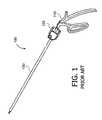
- FIG. 1depicts a typical example of an endoscopic instrument 100 .
- the instrument 100may include a handle 110 , a knob 120 , and a tubular member 130 .
- the handle 110may be one of a variety of conventional configurations, such as a grip handle shown in FIG. 1.
- a portion of the handle 110fits within a proximal end of the knob 120 , providing an axis about which the knob 120 can be rotated.
- a distal end of the knob 120may engage the proximal end of the tubular member 130 , such that any rotation of the knob 120 may cause the tubular member 130 to rotate as well.
- the distal end of the tubular member 130may include one of a variety of instruments or so-called end effectors.
- the distal endmay be equipped with jaws, cutting blades, or some other instrument, depending on the desired use of the endoscopic instrument.
- FIG. 2depicts a cross section of a knob 120 having a conventional ball and spring detent mechanism.
- a cylindrical drum 205having a plurality of detents 210 .
- a channel 215may extend partially through the knob 120 , the channel 215 being oriented radially with respect to the cylindrical drum 205 .
- the ball and spring mechanismis positioned within the channel 215 .
- a compression spring 220is used to hold a ball 225 in contact with the cylindrical drum 205 .
- a set screw 230may be used to seal the channel 215 .
- the set screw 230may also be used to adjust the amount of compression force that is applied to the spring 220 .
- the ball, spring, and set screwmay be separate components or may be integrated into a single component, as is known to the art.
- the portion of the handle that fits within the knobmay engage the cylindrical drum 205 , or the cylindrical drum 205 may be an integral part of the handle.
- the ball 225travels around the circumference of the cylindrical drum 205 .
- the spring 220pushes the ball 225 into the detent 210 . If additional rotational force is applied to the knob 120 , then the ball 225 is removed from the detent 210 .
- the amount of force needed to remove the ball 225 from the detent 210depends on a number of factors, including the shape and depth of the detent 210 , the shape and size of the ball 225 , and the amount of compression force applied by the spring 220 and/or set screw 230 .
- the spring 220is conventionally made of metal to provide sufficient compressive force. The movement of the ball 225 into and out of the detents 210 provides tactile feedback to the user.
- an endoscopic instrumenthaving a circular detent housing coupled to a first end of a knob.
- the circular detent housinghas a plurality of detents arranged along the perimeter of the detent housing.
- a tubular memberfixedly engages a second end of the knob.
- a detent ringis positioned coplanar to and within the perimeter of the detent housing.
- the detent ringhas at least one detent arm and at least a portion of the at least one detent arm engages at least a portion of the detent housing.
- a handleis coupled to the detent ring.
- the mechanismincludes a circular detent housing, a detent ring, and a handle.
- the detent housinghas a plurality of detents arranged along the circumference of the detent housing.
- the detent ringhas at least one detent arm and is positioned coplanar to and within the circumference of the detent housing, such that at least a portion of the at least one detent arm engages at least a portion of the detent housing.
- the handleengaging the detent ring such that a force applied to the handle causes the detent ring to rotate with respect to the circular detent housing.
- the circular detent housingis formed within the first end of the knob.
- the detent ringhas at least two arms.
- the two armsmay have the same length or have different lengths.
- the plurality of detentsare arranged at either regular or irregular intervals along the perimeter of the detent housing.
- FIG. 1is a plan view of an endoscopic instrument
- FIG. 2is a partial cross-section of the knob of an endoscopic instrument having a conventional ball and spring detent mechanism
- FIG. 3is an exploded view of the knob of an endoscopic instrument showing an exemplary embodiment of a detent mechanism in accordance the invention
- FIG. 4is a plan view of the proximal end of the knob
- FIGS. 5 a and 5 bare a plan views of two embodiments of the detent ring
- FIGS. 6 a , 6 b , and 6 care sequence drawings of a knob rotation
- FIG. 7is a plan view of another embodiment of the detent ring.
- the present inventionimproves upon the state of the art by providing a more reliable incremental rotational displacement mechanism for use with endoscopic instruments. Furthermore, the mechanism may be implemented using fewer components.
- FIG. 3is an exploded view of a knob 300 of an endoscopic instrument showing an exemplary embodiment of an incremental rotational displacement mechanism in accordance with the invention. It will be appreciated that the knob 300 shown in FIG. 3 replaces the knob 120 shown in FIG. 1 . Thus, from the perspective of the user, each of the knobs 300 , 120 performs an equivalent function.
- a cylindrical cavity 305is formed in a proximal end of the knob 300 .
- a plurality of scalloped detents 310Arranged around the circumference of the cavity 305 are a plurality of scalloped detents 310 .
- a detent ring 315may be disposed at least partially within the cavity 305 and in the same plane as the cavity 305 .
- a knob plug 320may be disposed at least partially within the cavity 305 and positioned proximally to the detent ring 315 .
- the knob plug 320provides a mechanical seal for the cavity 305 and retains the detent ring 315 in place.
- the shaft portion of the handle 110mates with a center hole of the detent ring 315 , thereby rotationally fixing the detent ring to the shaft portion 110 of the handle.
- FIG. 4shows a plan view of the knob 300 showing the cylindrical cavity 305 and the plurality of scalloped detents 310 .
- the knob 300may be formed from a variety of materials, such as polymers and metals, using conventional techniques.
- the knobmay be formed by injection molding an acetal resin, such as Delrin® 150 available from E.I. du Pont de Nemours and Company. If the knob 300 is injection molded, then the knob 300 , the cylindrical cavity 305 , and the plurality of scalloped detents 310 maybe formed from a single process step.
- the number of detents 310 and the distance between each of the detents 310may determine the angular resolution of the incremental rotational displacement mechanism.
- twelve detents 310are equally spaced around the perimeter of the cavity 305 , resulting in a granularity of about 30 degrees of angular resolution.
- the number of detentsmay be increased or decreased to provide a greater or lesser amount of angular resolution.
- detentsmay be absent from portions of the perimeter of the cavity, creating “dead zones”.
- FIG. 5 ashows a plan view of the detent ring 315 .
- the detent ringmay include a main body 510 and at least one arm 520 .
- One end of the arm 520may be connected to the main body 510 and the other end of the arm may terminate in a tab 530 .
- the arm 520may extend from one end of the main body 510 to another end of the main body 510 , with the tab 530 located along the length of the arm. In either case, the tab 530 may be shaped to engage the scalloped detents.
- the tab 530 and at least one arm 520are arranged such that the tab 530 moves in and out of the detents 310 as the detent ring 315 is rotated within the cavity 305 .
- the userexperiences some tactile feedback, similar to that felt with the conventional ball and spring mechanism shown in FIG. 2 .
- an opening 540may extend through the center of the main body 510 .
- the opening 540may have at least one flat portion.
- the shaft of the handlemay be “keyed” to the shape of the opening 540 , so that when the shaft is inserted into the opening, the shaft and the detent ring may be rotationally fixed.
- the material used to make the detent ring 315should be compatible with that material used to make the knob 300 . Factors used to determine compatibility may include chemical interaction. In addition, the material should be chosen to minimize any burring or wear of either the detent ring 315 or the detents 310 after repeated used.
- the detent ring 315may be formed using similar materials and techniques used to form the knob 300 . For example, the detent ring 315 may be formed by injection molding an acetal resin, such as the previously described Delrin® 150 .
- the amount of force needed to rotate the knob 300can be varied by changing the characteristics of the detent ring 315 .
- the thickness of at least one arm 540can be increased or decreased to provide a greater or lesser amount of resistance to movement with respect to the main body 510 .
- the composition of the material used to make the detent ring 315can be changed.
- other polymerscould be mixed with or substituted for the acetal resin used to make the detent ring 315 .
- metal or alloyscould be used to form all or part of the detent ring 315 . Examples of other suitable materials include stainless steel or nickel titanium alloys, such as nitinol.
- FIG. 6 ashows the detent ring 315 positioned within the cylindrical cavity 305 of the knob 300 .
- the shaft of the handle 110 and the knob plug 320are not shown.
- the tabs 530fully engage the detents 310 .
- the knob 300maybe rotated counter-clockwise with respect to the detent ring 315 , as indicated by the arrow 601 .
- a portion of the detents 310assert a radial force against the tab 530 portions of the arms 520 , pushing the arms 520 toward the main body 510 portion of the detent ring 315 . This is indicated by the arrows 602 , 603 in FIG. 6 b .
- the knob 300may continue to be rotated counter-clockwise until the tabs 530 fully engage another pair of detents 310 , as shown in FIG. 6 c .
- FIGS. 6 a , 6 b , and 6 cshow the knob 300 being rotated counter-clockwise, the knob 300 may also be rotated clockwise. Due to the symmetrical shape of the tab 530 , the detent ring 315 interacts with the detents 310 in the same manner regardless of which direction the knob 300 is rotated.
- the number of detents 310 and the distance between each of the detents 310may determine the angular resolution of the incremental rotational displacement mechanism.
- the angular resolution of the incremental rotational displacement mechanismmay also be determined by the length of the arms of the detent ring.
- FIG. 7depicts an embodiment of the detent ring 315 having arms of unequal lengths.
- a first armmay have length L 1 and a second arm may have length L 2 , where L 2 is greater than L 1 .
- one tab 530may be engaged in a detent while the other tab is situated somewhere between two adjacent detents and is thus disengaged.
- the engaged tabmay become disengaged from its detent and the previously disengaged tab may become engaged in another detent.
- the effective angular rotation of the incremental rotational displacement mechanismmay be somewhere between the angular distance between two adjacent detents.
Landscapes
- Health & Medical Sciences (AREA)
- Surgery (AREA)
- Life Sciences & Earth Sciences (AREA)
- Medical Informatics (AREA)
- Nuclear Medicine, Radiotherapy & Molecular Imaging (AREA)
- Engineering & Computer Science (AREA)
- Biomedical Technology (AREA)
- Heart & Thoracic Surgery (AREA)
- Molecular Biology (AREA)
- Animal Behavior & Ethology (AREA)
- General Health & Medical Sciences (AREA)
- Public Health (AREA)
- Veterinary Medicine (AREA)
- Ophthalmology & Optometry (AREA)
- Surgical Instruments (AREA)
- Endoscopes (AREA)
Abstract
Description
Claims (14)
Priority Applications (5)
| Application Number | Priority Date | Filing Date | Title |
|---|---|---|---|
| US09/972,170US6679874B2 (en) | 2001-10-05 | 2001-10-05 | Ratcheting mechanism for endoscopic instruments |
| EP02776147AEP1437967A1 (en) | 2001-10-05 | 2002-10-04 | Ratcheting mechanism for endoscopic instruments |
| JP2003533778AJP4295105B2 (en) | 2001-10-05 | 2002-10-04 | Ratchet mechanism for endoscopic instruments |
| PCT/US2002/031799WO2003030741A1 (en) | 2001-10-05 | 2002-10-04 | Ratcheting mechanism for endoscopic instruments |
| CA002462869ACA2462869A1 (en) | 2001-10-05 | 2002-10-04 | Ratcheting mechanism for endoscopic instruments |
Applications Claiming Priority (1)
| Application Number | Priority Date | Filing Date | Title |
|---|---|---|---|
| US09/972,170US6679874B2 (en) | 2001-10-05 | 2001-10-05 | Ratcheting mechanism for endoscopic instruments |
Publications (2)
| Publication Number | Publication Date |
|---|---|
| US20030069565A1 US20030069565A1 (en) | 2003-04-10 |
| US6679874B2true US6679874B2 (en) | 2004-01-20 |
Family
ID=25519284
Family Applications (1)
| Application Number | Title | Priority Date | Filing Date |
|---|---|---|---|
| US09/972,170Expired - LifetimeUS6679874B2 (en) | 2001-10-05 | 2001-10-05 | Ratcheting mechanism for endoscopic instruments |
Country Status (5)
| Country | Link |
|---|---|
| US (1) | US6679874B2 (en) |
| EP (1) | EP1437967A1 (en) |
| JP (1) | JP4295105B2 (en) |
| CA (1) | CA2462869A1 (en) |
| WO (1) | WO2003030741A1 (en) |
Cited By (6)
| Publication number | Priority date | Publication date | Assignee | Title |
|---|---|---|---|---|
| US20060054642A1 (en)* | 2003-01-21 | 2006-03-16 | Spray Plast S.P.A. | Simplified sprayer device |
| US20080147059A1 (en)* | 2002-12-11 | 2008-06-19 | Boston Scientific Scimed, Inc. | Angle indexer for medical devices |
| US20130205936A1 (en)* | 2012-02-06 | 2013-08-15 | Arthrex, Inc. | Arthroscope rotation mechanisms and methods of endoscopic rotation |
| US20160143512A1 (en)* | 2014-11-24 | 2016-05-26 | Gyrus Acmi, Inc. D.B.A Olympus Surgical Technologies America | Adjustable endoscope sheath |
| US20230093551A1 (en)* | 2020-02-14 | 2023-03-23 | Covidien Lp | Surgical stapling device |
| US11717143B2 (en)* | 2017-07-31 | 2023-08-08 | Sony Olympus Medical Solutions Inc. | Endoscope camera head |
Families Citing this family (5)
| Publication number | Priority date | Publication date | Assignee | Title |
|---|---|---|---|---|
| GB2563567B (en) | 2017-05-05 | 2022-01-05 | Flexicare Group Ltd | Intubation devices |
| US10918393B2 (en)* | 2017-11-05 | 2021-02-16 | Grena Usa Llc | Surgical appliance |
| PL239734B1 (en)* | 2019-12-27 | 2022-01-03 | Konmex Spolka Z Ograniczona Odpowiedzialnoscia | Laparoscopic instrument |
| EP4106604A1 (en)* | 2020-03-10 | 2022-12-28 | VTI Medical, Inc. | Multi-angle imaging platform |
| RU205495U1 (en)* | 2020-03-24 | 2021-07-16 | Государственное бюджетное учреждение здравоохранения города Москвы городская клиническая больница имени С.П. Боткина департамента здравоохранения города Москвы (ГБУЗ ГКБ им. С.П. Боткина ДЗМ) | ARTHROSCOPE LIGHT GAUGE |
Citations (7)
| Publication number | Priority date | Publication date | Assignee | Title |
|---|---|---|---|---|
| US4207873A (en)* | 1977-05-16 | 1980-06-17 | American Cystoscope Makers, Inc. | Endoscope deflection control |
| US5174300A (en)* | 1991-04-04 | 1992-12-29 | Symbiosis Corporation | Endoscopic surgical instruments having rotatable end effectors |
| US5556416A (en) | 1993-10-12 | 1996-09-17 | Valleylab, Inc. | Endoscopic instrument |
| US5827323A (en) | 1993-07-21 | 1998-10-27 | Charles H. Klieman | Surgical instrument for endoscopic and general surgery |
| US5836960A (en) | 1994-09-23 | 1998-11-17 | United States Surgical Corporation | Endoscopic surgical apparatus with rotation lock |
| US5893835A (en)* | 1997-10-10 | 1999-04-13 | Ethicon Endo-Surgery, Inc. | Ultrasonic clamp coagulator apparatus having dual rotational positioning |
| US6068647A (en) | 1997-10-10 | 2000-05-30 | Ethicon Endo-Surgery, Inc. | Ultrasonic clamp coagulator apparatus having improved clamp arm tissue pad |
- 2001
- 2001-10-05USUS09/972,170patent/US6679874B2/ennot_activeExpired - Lifetime
- 2002
- 2002-10-04EPEP02776147Apatent/EP1437967A1/ennot_activeWithdrawn
- 2002-10-04WOPCT/US2002/031799patent/WO2003030741A1/enactiveApplication Filing
- 2002-10-04CACA002462869Apatent/CA2462869A1/ennot_activeAbandoned
- 2002-10-04JPJP2003533778Apatent/JP4295105B2/ennot_activeExpired - Lifetime
Patent Citations (7)
| Publication number | Priority date | Publication date | Assignee | Title |
|---|---|---|---|---|
| US4207873A (en)* | 1977-05-16 | 1980-06-17 | American Cystoscope Makers, Inc. | Endoscope deflection control |
| US5174300A (en)* | 1991-04-04 | 1992-12-29 | Symbiosis Corporation | Endoscopic surgical instruments having rotatable end effectors |
| US5827323A (en) | 1993-07-21 | 1998-10-27 | Charles H. Klieman | Surgical instrument for endoscopic and general surgery |
| US5556416A (en) | 1993-10-12 | 1996-09-17 | Valleylab, Inc. | Endoscopic instrument |
| US5836960A (en) | 1994-09-23 | 1998-11-17 | United States Surgical Corporation | Endoscopic surgical apparatus with rotation lock |
| US5893835A (en)* | 1997-10-10 | 1999-04-13 | Ethicon Endo-Surgery, Inc. | Ultrasonic clamp coagulator apparatus having dual rotational positioning |
| US6068647A (en) | 1997-10-10 | 2000-05-30 | Ethicon Endo-Surgery, Inc. | Ultrasonic clamp coagulator apparatus having improved clamp arm tissue pad |
Cited By (14)
| Publication number | Priority date | Publication date | Assignee | Title |
|---|---|---|---|---|
| US20080147059A1 (en)* | 2002-12-11 | 2008-06-19 | Boston Scientific Scimed, Inc. | Angle indexer for medical devices |
| US8758339B2 (en)* | 2002-12-11 | 2014-06-24 | Boston Scientific Scimed, Inc. | Angle indexer for medical devices |
| US20060054642A1 (en)* | 2003-01-21 | 2006-03-16 | Spray Plast S.P.A. | Simplified sprayer device |
| US7175056B2 (en)* | 2003-01-21 | 2007-02-13 | Spray Plast S.P.A. | Simplified sprayer device |
| US20130205936A1 (en)* | 2012-02-06 | 2013-08-15 | Arthrex, Inc. | Arthroscope rotation mechanisms and methods of endoscopic rotation |
| US9146576B2 (en)* | 2012-02-06 | 2015-09-29 | Arthrex, Inc. | Arthroscope rotation mechanisms and methods of endoscopic rotation |
| US20160143512A1 (en)* | 2014-11-24 | 2016-05-26 | Gyrus Acmi, Inc. D.B.A Olympus Surgical Technologies America | Adjustable endoscope sheath |
| US9585547B2 (en)* | 2014-11-24 | 2017-03-07 | Gyrus Acmi, Inc. | Adjustable endoscope sheath |
| US10918263B2 (en) | 2014-11-24 | 2021-02-16 | Gyrus Acmi, Inc. | Adjustable endoscope sheath |
| US11684244B2 (en) | 2014-11-24 | 2023-06-27 | Gyrs ACMI, Inc. | Adjustable endoscope sheath |
| US11717143B2 (en)* | 2017-07-31 | 2023-08-08 | Sony Olympus Medical Solutions Inc. | Endoscope camera head |
| US12402785B2 (en) | 2017-07-31 | 2025-09-02 | Sony Olympus Medical Solutions Inc. | Endoscope camera head |
| US20230093551A1 (en)* | 2020-02-14 | 2023-03-23 | Covidien Lp | Surgical stapling device |
| US12220124B2 (en)* | 2020-02-14 | 2025-02-11 | Covidien Lp | Surgical stapling device |
Also Published As
| Publication number | Publication date |
|---|---|
| US20030069565A1 (en) | 2003-04-10 |
| CA2462869A1 (en) | 2003-04-17 |
| JP2005505333A (en) | 2005-02-24 |
| JP4295105B2 (en) | 2009-07-15 |
| EP1437967A1 (en) | 2004-07-21 |
| WO2003030741A1 (en) | 2003-04-17 |
Similar Documents
| Publication | Publication Date | Title |
|---|---|---|
| US12402912B2 (en) | Multi-diameter cannula depth limiter | |
| US12343038B2 (en) | Pinch-to-release cannula depth limiter | |
| US5593402A (en) | Laparoscopic device having a detachable distal tip | |
| US6432085B1 (en) | Self-retaining surgical access instrument | |
| EP1262150B1 (en) | Trocar with reinforced obturator shaft | |
| JP3421117B2 (en) | Surgical instruments | |
| EP0677275B1 (en) | Surgical instrument | |
| US9655643B2 (en) | Bladeless optical obturator | |
| US11986215B2 (en) | Universal size multi-walled elastomer cannula depth limiter | |
| US5766196A (en) | Surgical instrument with steerable distal end | |
| US5984939A (en) | Multifunctional grasping instrument with cutting member and operating channel for use in endoscopic and non-endoscopic procedures | |
| US9351751B2 (en) | Swinging bars with axial wheels to drive articulating cables | |
| US6679874B2 (en) | Ratcheting mechanism for endoscopic instruments | |
| EP1348386A1 (en) | Trocar with a reinforced seal | |
| US20150209025A1 (en) | Access Device | |
| US20100087711A1 (en) | Repeatably flexible surgical instrument | |
| WO1999030622A2 (en) | Low profile endoscopic surgical instruments | |
| JP2010099460A (en) | Laparoscopic instrument and related surgical method | |
| EP2289439A2 (en) | Surgical portal apparatus including gear and lookout assembly | |
| EP3861947B1 (en) | Surgical access device including anchor with ratchet mechanism | |
| EP1889580A2 (en) | Surgical seal assembly | |
| EP3698741A1 (en) | Access assembly including flexible cannula | |
| US12426802B2 (en) | Surgical sizer sound |
Legal Events
| Date | Code | Title | Description |
|---|---|---|---|
| AS | Assignment | Owner name:WECK CLOSURE SYSTEMS, INC., NORTH CAROLINA Free format text:ASSIGNMENT OF ASSIGNORS INTEREST;ASSIGNOR:MISER, JOHN D.;REEL/FRAME:012655/0489 Effective date:20020130 | |
| STCF | Information on status: patent grant | Free format text:PATENTED CASE | |
| AS | Assignment | Owner name:TECHNOLOGY HOLDING COMPANY II, DELAWARE Free format text:ASSIGNMENT OF ASSIGNORS INTEREST;ASSIGNOR:PILLING WECK INCORPORATED DBA WECK CLOSURE SYSTEMS;REEL/FRAME:017388/0858 Effective date:20041207 | |
| FPAY | Fee payment | Year of fee payment:4 | |
| FPAY | Fee payment | Year of fee payment:8 | |
| FPAY | Fee payment | Year of fee payment:12 | |
| AS | Assignment | Owner name:PILLING WECK INCORPORATED, PENNSYLVANIA Free format text:CERTIFICATE OF CANCELLATION;ASSIGNOR:WECK CLOSURE SYSTEMS, LLC;REEL/FRAME:041638/0422 Effective date:20030521 | |
| AS | Assignment | Owner name:JPMORGAN CHASE BANK, N.A., AS ADMINISTRATIVE AGENT Free format text:SECURITY INTEREST;ASSIGNOR:TECHNOLOGY HOLDING COMPANY II;REEL/FRAME:041760/0414 Effective date:20170217 | |
| AS | Assignment | Owner name:TECHNOLOGY HOLDING COMPANY II, DELAWARE Free format text:ASSIGNMENT OF ASSIGNORS INTEREST;ASSIGNOR:WECK CLOSURE SYSTEMS, LLC;REEL/FRAME:046800/0365 Effective date:20180809 | |
| AS | Assignment | Owner name:TELEFLEX MEDICAL INCORPORATED, PENNSYLVANIA Free format text:MERGER;ASSIGNOR:TECHNOLOGY HOLDING COMPANY II;REEL/FRAME:049342/0541 Effective date:20190503 | |
| AS | Assignment | Owner name:JPMORGAN CHASE BANK, N.A., AS ADMINISTRATIVE AGENT Free format text:SECURITY INTEREST;ASSIGNOR:TELEFLEX MEDICAL INCORPORATED;REEL/FRAME:050620/0904 Effective date:20190925 Owner name:JPMORGAN CHASE BANK, N.A., AS ADMINISTRATIVE AGENT, ILLINOIS Free format text:SECURITY INTEREST;ASSIGNOR:TELEFLEX MEDICAL INCORPORATED;REEL/FRAME:050620/0904 Effective date:20190925 |