US6679873B2 - Method for using a steerable catheter device - Google Patents
Method for using a steerable catheter deviceDownload PDFInfo
- Publication number
- US6679873B2 US6679873B2US10/462,182US46218203AUS6679873B2US 6679873 B2US6679873 B2US 6679873B2US 46218203 AUS46218203 AUS 46218203AUS 6679873 B2US6679873 B2US 6679873B2
- Authority
- US
- United States
- Prior art keywords
- catheter
- sheath
- handle
- elongated
- lock
- Prior art date
- Legal status (The legal status is an assumption and is not a legal conclusion. Google has not performed a legal analysis and makes no representation as to the accuracy of the status listed.)
- Expired - Fee Related
Links
- 238000000034methodMethods0.000titleclaimsdescription22
- 239000000463materialSubstances0.000claimsdescription13
- 239000000523sampleSubstances0.000claimsdescription13
- 210000005166vasculatureAnatomy0.000claimsdescription8
- 239000012530fluidSubstances0.000abstractdescription13
- 238000004891communicationMethods0.000abstractdescription10
- 230000002262irrigationEffects0.000abstractdescription9
- 238000003973irrigationMethods0.000abstractdescription9
- 238000010276constructionMethods0.000description4
- 230000004913activationEffects0.000description3
- 238000012986modificationMethods0.000description3
- 230000004048modificationEffects0.000description3
- 230000001954sterilising effectEffects0.000description3
- 238000004659sterilization and disinfectionMethods0.000description3
- 229920004943Delrin®Polymers0.000description2
- 230000004075alterationEffects0.000description2
- 210000003811fingerAnatomy0.000description2
- 238000002324minimally invasive surgeryMethods0.000description2
- 210000000056organAnatomy0.000description2
- 230000035945sensitivityEffects0.000description2
- 238000012800visualizationMethods0.000description2
- 206010000060Abdominal distensionDiseases0.000description1
- SXRSQZLOMIGNAQ-UHFFFAOYSA-NGlutaraldehydeChemical compoundO=CCCCC=OSXRSQZLOMIGNAQ-UHFFFAOYSA-N0.000description1
- 230000009471actionEffects0.000description1
- 239000000853adhesiveSubstances0.000description1
- 230000001070adhesive effectEffects0.000description1
- 229910045601alloyInorganic materials0.000description1
- 239000000956alloySubstances0.000description1
- 210000003484anatomyAnatomy0.000description1
- 230000008901benefitEffects0.000description1
- 239000008280bloodSubstances0.000description1
- 210000004369bloodAnatomy0.000description1
- 230000006835compressionEffects0.000description1
- 238000007906compressionMethods0.000description1
- 229940039231contrast mediaDrugs0.000description1
- 239000002872contrast mediaSubstances0.000description1
- 238000012864cross contaminationMethods0.000description1
- 238000002224dissectionMethods0.000description1
- 239000000428dustSubstances0.000description1
- 210000005224forefingerAnatomy0.000description1
- 230000006870functionEffects0.000description1
- 210000004907glandAnatomy0.000description1
- 238000003780insertionMethods0.000description1
- 230000037431insertionEffects0.000description1
- 238000004519manufacturing processMethods0.000description1
- 230000013011matingEffects0.000description1
- 239000002184metalSubstances0.000description1
- 229920001296polysiloxanePolymers0.000description1
- 230000009467reductionEffects0.000description1
- 238000007789sealingMethods0.000description1
- 239000010935stainless steelSubstances0.000description1
- 229910001220stainless steelInorganic materials0.000description1
- 210000003813thumbAnatomy0.000description1
- 238000011282treatmentMethods0.000description1
- 238000011277treatment modalityMethods0.000description1
- 230000002792vascularEffects0.000description1
Images


Classifications
- A—HUMAN NECESSITIES
- A61—MEDICAL OR VETERINARY SCIENCE; HYGIENE
- A61M—DEVICES FOR INTRODUCING MEDIA INTO, OR ONTO, THE BODY; DEVICES FOR TRANSDUCING BODY MEDIA OR FOR TAKING MEDIA FROM THE BODY; DEVICES FOR PRODUCING OR ENDING SLEEP OR STUPOR
- A61M25/00—Catheters; Hollow probes
- A61M25/01—Introducing, guiding, advancing, emplacing or holding catheters
- A61M25/0105—Steering means as part of the catheter or advancing means; Markers for positioning
- A61M25/0133—Tip steering devices
- A61M25/0152—Tip steering devices with pre-shaped mechanisms, e.g. pre-shaped stylets or pre-shaped outer tubes
- A—HUMAN NECESSITIES
- A61—MEDICAL OR VETERINARY SCIENCE; HYGIENE
- A61M—DEVICES FOR INTRODUCING MEDIA INTO, OR ONTO, THE BODY; DEVICES FOR TRANSDUCING BODY MEDIA OR FOR TAKING MEDIA FROM THE BODY; DEVICES FOR PRODUCING OR ENDING SLEEP OR STUPOR
- A61M25/00—Catheters; Hollow probes
- A61M25/0067—Catheters; Hollow probes characterised by the distal end, e.g. tips
- A61M25/0068—Static characteristics of the catheter tip, e.g. shape, atraumatic tip, curved tip or tip structure
- A61M25/0069—Tip not integral with tube
- A—HUMAN NECESSITIES
- A61—MEDICAL OR VETERINARY SCIENCE; HYGIENE
- A61M—DEVICES FOR INTRODUCING MEDIA INTO, OR ONTO, THE BODY; DEVICES FOR TRANSDUCING BODY MEDIA OR FOR TAKING MEDIA FROM THE BODY; DEVICES FOR PRODUCING OR ENDING SLEEP OR STUPOR
- A61M25/00—Catheters; Hollow probes
- A61M25/01—Introducing, guiding, advancing, emplacing or holding catheters
- A61M2025/018—Catheters having a lateral opening for guiding elongated means lateral to the catheter
- A—HUMAN NECESSITIES
- A61—MEDICAL OR VETERINARY SCIENCE; HYGIENE
- A61M—DEVICES FOR INTRODUCING MEDIA INTO, OR ONTO, THE BODY; DEVICES FOR TRANSDUCING BODY MEDIA OR FOR TAKING MEDIA FROM THE BODY; DEVICES FOR PRODUCING OR ENDING SLEEP OR STUPOR
- A61M25/00—Catheters; Hollow probes
- A61M25/01—Introducing, guiding, advancing, emplacing or holding catheters
- A61M25/06—Body-piercing guide needles or the like
- A61M25/0662—Guide tubes
- A61M2025/0681—Systems with catheter and outer tubing, e.g. sheath, sleeve or guide tube
- A—HUMAN NECESSITIES
- A61—MEDICAL OR VETERINARY SCIENCE; HYGIENE
- A61M—DEVICES FOR INTRODUCING MEDIA INTO, OR ONTO, THE BODY; DEVICES FOR TRANSDUCING BODY MEDIA OR FOR TAKING MEDIA FROM THE BODY; DEVICES FOR PRODUCING OR ENDING SLEEP OR STUPOR
- A61M25/00—Catheters; Hollow probes
- A61M25/0067—Catheters; Hollow probes characterised by the distal end, e.g. tips
- A61M25/0068—Static characteristics of the catheter tip, e.g. shape, atraumatic tip, curved tip or tip structure
- A61M25/007—Side holes, e.g. their profiles or arrangements; Provisions to keep side holes unblocked
- A—HUMAN NECESSITIES
- A61—MEDICAL OR VETERINARY SCIENCE; HYGIENE
- A61M—DEVICES FOR INTRODUCING MEDIA INTO, OR ONTO, THE BODY; DEVICES FOR TRANSDUCING BODY MEDIA OR FOR TAKING MEDIA FROM THE BODY; DEVICES FOR PRODUCING OR ENDING SLEEP OR STUPOR
- A61M25/00—Catheters; Hollow probes
- A61M25/0067—Catheters; Hollow probes characterised by the distal end, e.g. tips
- A61M25/0074—Dynamic characteristics of the catheter tip, e.g. openable, closable, expandable or deformable
- A—HUMAN NECESSITIES
- A61—MEDICAL OR VETERINARY SCIENCE; HYGIENE
- A61M—DEVICES FOR INTRODUCING MEDIA INTO, OR ONTO, THE BODY; DEVICES FOR TRANSDUCING BODY MEDIA OR FOR TAKING MEDIA FROM THE BODY; DEVICES FOR PRODUCING OR ENDING SLEEP OR STUPOR
- A61M25/00—Catheters; Hollow probes
- A61M25/01—Introducing, guiding, advancing, emplacing or holding catheters
- A61M25/0105—Steering means as part of the catheter or advancing means; Markers for positioning
- A61M25/0133—Tip steering devices
- A61M25/0136—Handles therefor
Definitions
- the present inventionrelates to a steerable catheter device, and more particularly to a device useful in minimally invasive surgery, urology, gynecology and hysteroscopy or the like.
- the present inventionis of lightweight inexpensively constructed steerable catheter device including a handle means which can be held like a pencil.
- the handle meansprovides greater sensitivity and tactile feel to the user than is possible with present day devices of this type. Greater sensitivity is provided by the reduction in weight on the handle.
- the handle meanscan be shaped as a pistol grip. When shaped as a pistol grip, the probe is constructed so that activation of the handle causes the motion of the probe to be advanced.
- the activation portion of the steerable cathetercan be designed as a reusable piece, since the activation portion is more robust.
- the small diameter catheterwould be disposable, and provide much simpler delivery to the patient. Reusing portions of the steerable catheter would also lower costs because less material is disposed of with each use.
- the handle meanssupports an elongated outer sheath and an elongated catheter extends through the sheath.
- the catheteris movable lengthwise of the sheath and is rotatable with respect to the sheath.
- the outer end of the cathetercomprises a memory tip which causes the tip to be disposed at a desired angle to the sheath when the tip is extended a certain distance from the sheath.
- the sheathmay be substantially rigid, or it may be formed of flexible material. In either case, the catheter is more flexible than the sheath. When the sheath is of flexible construction, complex shapes and bends can be created by rotating the catheter within the sheath. Moreover, with a flexible sheath, the invention may be used not only as a steering instrument but also as a dissection tool.
- the inner cathetercan be more flexible than would be normally deemed safe because inner catheter is able to secure and derive the wall thickness and strength from the sheath. This construction significantly reduces the potential for breakage.
- the handle meansincludes a body portion which is connected to the sheath and a handle portion which is connected to the catheter.
- the handle portionis movable with respect to the body portion. These two portions have engageable shoulders formed thereon to limit movement in opposite directions of the catheter relative to the sheath.
- the sheathmay be grasped in one hand of a user to hold the sheath and body portion in position while the other hand manipulates the handle portion to advance or retract the catheter with respect to the sheath and to additionally rotate the catheter with respect to the sheath.
- the handleIn the pistol grip configuration, the handle is under a spring-loaded force to maintain a backpressure on the handle. The operation may therefore be accomplished in a one handed function. Squeezing the handle causes the insertion of the inner catheter within the outer sheath (as indicated above). A knurled knob on the rotatable portion of the instrument allows the user to adjust the position of the probe by extending a finger and dialing the appropriate position.
- a suitable medical devicecan be inserted and advanced through the catheter.
- an endoscopemay be advanced to view tissue more closely, or it can be withdrawn to provide a wider field of view.
- the inner lumencan be multi lumen thereby allowing for more than one instrument or device to be inserted (up to the limits of device flexibility). For example, both a small diameter endoscope could be inserted in conjunction with another device; thus delivering both visualization and treatment modalities. Because of the lumens of the inner catheter are adjusted simultaneously (i.e. they are fixed in relative position), the user has the ability to easily move, visualize and deliver the treatment without the additional complication of relative space—relative relationship to each instrument.
- a first lock meansis supported by the handle means for adjusting the force required to advance and retract the catheter, or to lock the catheter in place relative to the sheath.
- a second lock meansis provided for locking a medical device in position within the catheter. This second lock means can also be adjusted to vary the force required to advance and retract the medical device, if so desired.
- the catheteris spaced from the sheath to provide an annular channel there between.
- the outer end of the sheathhas holes formed there through in communication with the annular channel.
- a fittingis supported by the handle means and has a bore therein in fluid communication with the annular channel.
- the fittingis also in fluid communication with an irrigation inflow and aspiration outflow tube to allow a constant interchange of fluids within a patient's body cavity or organ to clear the surgical site of debris or blood.
- the holes in the outer end of the sheathallow irrigation media to be discharged therefrom evenly without a high pressure point.
- the irrigation systemcan be used in the delivery of a distension media, a contrast media, or any other desired media.
- the relationship of irrigation and aspirationcan be altered in that the aspiration can be from the outer tube with the irrigation from the inner tube—the application of the fenestrations on the outer tube preclude the adherence to the tissue wall via the suction creating a high vacuum point.
- the steerable catheter of the present inventionis inexpensive to manufacture, and its size as it relates to anatomical structures provides a device which is far more comfortable to the patient.
- the medical device employedis an endoscope
- smaller endoscopesmay be interchanged for larger ones as the endoscopes are introduced into smaller diameter channels of the patient.
- sterilization thereofis far more a complete and simpler to perform.
- the used outer sheaths and cathetersare simply disposed of and replaced with new items, while the inner scope and other materials may (if applicable) be sterilized.
- the systemcan be used in conjunction with vascular procedure—specially in those instances where there is the use of guidewires.
- guidewiresare used as a leading device—introduced and passed into the area of the vasculature where the larger instrument could either not get to due to size, conformability—or other anatomical issues.
- the guidewireis first introduced into the human vasculature. After the guidewire is in place in the body, the guidewire is introduced into the lumen of the instrument—at the active tip. The guidewire is threaded through the catheter until the end of the guidewire exits the rear port of the instrument. The catheter is then introduced into the vasculature, and delivered to the appropriate surgical site by following the guidewire. Because the guidewire is smaller than the instrument, the use of the guidewire allows the instrument tip to reach the desired specific intervention site.
- the previously described systemcan be designed so that it mates with an ultrasonic energy source/system.
- the ultrasonic probeis introduced into the delivery catheter.
- the ultrasonic probehas a wide portion which is semi rigid. This wide portion mates with steerable catheter delivery section.
- the flexible thin portion of the proberesides within the flexible portion of the delivery system.
- the larger more rigid section of the probedoes not exhibit vibration patterns. Therefore, the mating of the two surfaces is not problematic (which might be a problem if the large section vibrated).
- the two sectionsmay be “hard mated” together.
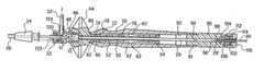
- FIG. 1is a top perspective view of the invention device
- FIG. 2is a longitudinal section through the handle means and adjacent portions of the structure of FIG. 1 showing certain elements in disassembled position;
- FIG. 3is an enlarged view of a portion of the structure shown in FIG. 2 with the handle portions in different relative position to one another;
- FIG. 4is an enlarged section taken along line 4 — 4 of FIG. 3;
- FIG. 5is an enlarged view of a portion of the structure of FIG. 3 indicated by line 5 — 5 ;
- FIG. 6is an enlarged view of a portion of the structure of FIG. 2 indicated by line 6 — 6 ;
- FIG. 7is an enlarged cross-section of a portion of the structure shown in FIG. 2;
- FIG. 8in an enlarged view partly broken away of a portion of the structure of FIG. 1 indicated by line 8 — 8 ;
- FIG. 9is a view partly broken away showing the outer end of the device shown in FIG. 1;
- FIG. 10is an enlarged view partly in section of the structure shown in FIG. 9;
- FIG. 11is an enlarged sectional view taken along line 11 — 11 of FIG. 10;
- FIG. 12is a perspective view of another embodiment of the invention.
- FIG. 1A handle means 20 is connected to a fitting 22 which is in turn connected to an attaching means 24 fixed to an outer sheath 26 .
- a catheter tip 28which is connected to a catheter hereinafter described, extends from the outer end of the sheath, and a medical device 30 such as an endoscope extends through the handle means and is supported within the catheter.
- the fitting 24is connected to an irrigation inflow and aspiration outflow tube 32 which has a suitable connector such as a female luer connector at the outer end thereof.
- the connectoris covered by a conventional dust cap 36 when it is not connected to any cooperating equipment.
- the handle meansincludes a body portion 40 and a handle portion 42 which is slidably and rotatably supported on the body portion.
- the body portion and the handle portionare preferably formed of a suitable plastic such as Delrin.
- the body portionincludes an enlarged part 44 which is adapted to be grasped and rotated during use of the device for a purpose hereinafter described.
- the enlarged part 44has a threaded bore 46 formed therein which is threadedly connected to a threaded outer surface on a cylindrical portion 48 of the fitting 22 .
- the body portion 40includes a cylindrical portion 50 having a bore 52 formed therethrough, portion 50 terminating an outer end having a radially extending annular shoulder 54 thereon.
- a longitudinally extending slot 56is formed on the outer end of the portion 50 for providing a resilient end portion.
- the cylindrical portion 50has four equally spaced radially extending slots 60 extending inwardly from the outer surface of an intermediate part of the portion 50 .
- the slotsare in communication with the bore 52 .
- Arcuate shoulders 62extend radially outwardly from the portion 50 , the shoulders extending between adjacent slot 60 . These slots provide a resilient intermediate part of the body portion 40 .
- the outer surface of the handle portion 42is configured so as to fit comfortably in the hand of a user and includes a depression 70 for receiving the thumb and forefinger of the user's hand when using the device.
- the forward part of the depressionmay be provided with a series of spaced protrusions 72 extending around the handle portion to prevent a user's fingers from slipping when rotating the handle portion.
- the handle portionhas a first bore 74 formed therein which snugly receives cylindrical part 50 of the body portion.
- the bore 74is in communication with a second bore 76 formed within the handle portion.
- An annular inwardly extending shoulder means 78is formed between bores 74 and 76 .
- annular shoulder means 80is formed on the forward end of portion 42 .
- the annular shoulder means 80is in engagement with an outwardly extending shoulder means 82 on the enlarged part 44 of the body portion 40 for limiting movement of the handle portion to the left as seen in this figure.
- the handle portion 42is moved to the right relative to the body portion 40 as seen in FIG. 3
- movement of the handle portion to the rightis limited by engagement of the shoulder means 78 of the handle portion.with the shoulders 62 on the body portion.
- the slot 56 in the end of the body portionpermits the shoulder means 54 to be deflected so that the body means may be inserted through the bore 74 of the handle portion.
- the slots 60 formed in the body meanspermit the intermediate part of the body portion to be deflected as shown in this figure so that the shoulders 62 may pass through the bore when portions 40 and 42 are assembled.
- the handle portion 42includes an element 90 which also may be formed of any suitable plastic, such as Delrin.
- the element 90has a reduced end portion 91 which is received within a bore 92 formed within the handle portion 42 .
- the portions 42 and 91are adhesively secured in position.
- the element 90has a bore 94 formed therethrough which joins with a smaller bore 96 to form an annular shoulder 98 therebetween.
- a catheter 29is snugly received within the bore 94 , and the rear end 281 of the catheter abuts shoulder 98 .
- the catheteris adhesively secured in place within element 90 .
- the element 90also includes an opposite reduced end portion 100 with an external thread formed thereon.
- a bore 102is formed within the end portion 100 and has disposed therein a resilient compressible lock member 104 in the form of a conventional silicone gland or the like having a bore formed therethrough which slidably receives a medical device 30 which extends through the catheter.
- An end cap 110also formed of a suitable plastic material includes an outer cylindrical portion 112 having an internal thread formed thereon which is in engagement with the external thread formed on end portion 100 of element 90 .
- the end capalso includes an inner cylindrical portion 114 the end surface of which is adapted to engage the lock member 104 .
- the end surface of the inner cylindrical portion 114engages the lock member 104 to compress it in a longitudinal direction. This compression causes the lock member to clamp the medical device 30 to adjust the frictional resistance to lengthwise movement of the medical device or to lock the medical device in position lengthwise of the catheter.
- the fitting 22includes a cylindrical portion 120 having an internally threaded bore 122 therein.
- the threaded bore 122is in communication with a side port 124 .
- the side port 124is connected to and is in fluid communication with the tube 32 .
- a bore 130is formed within the cylindrical portion 48 of the fitting.
- a resilient compressible lock member 132 in the form of a conventional lip sealmay be formed of the same material as lock member 104 previously described.
- the lip sealincludes a wall 134 having a hole therein for slidably receiving the catheter 29 .
- the wall 134joins with a cylindrical wall 136 which joins with a radial wall 138 which joins with a lip 140 defining a bore therethrough for slidably receiving the catheter.
- a conventional o-ring 142is disposed around the lip 140 for retaining it in sealing relationship with the catheter 29 .
- the lock member 132When the enlarged part 44 of the body portion is rotated to thread the body portion to the left as seen in FIG. 6, the lock member 132 is compressed and tightens down on the catheter extending therethrough.
- the lock membermay be compressed to varying degrees to adjust the resistance to longitudinal movement of the catheter and handle portion relative to the sheath and body portion, or it may be compressed to such extent that the catheter is locked against longitudinal movement relative to the sheath. This locking action can be accomplished in an infinite number of positions between the two spaced limits of relative movement in opposite directions of the catheter relative to the sheath.
- the attaching means 24comprises a conventional luer fitting having thread means 150 at one end thereon.
- the attaching means 24is threaded into the internally threaded bore 122 of the fitting 22 .
- a first bore 152is formed through the means 24 and is of greater diameter than the outer diameter of the catheter 29 which passes therethrough to allow fluid to pass through the bore 152 and around the catheter.
- a bore 154 of greater diameter than the bore 152is provided within the attaching means 24 , and an annular shoulder 156 is defined between the two bores.
- the inner end 261 of the sheath 26fits within the bore 154 and is adhesively secured thereto with the inner end surface abutting shoulder 156 .
- the outer surface of the catheteris spaced from the inner surface of the sheath to form an annular channel 158 therebetween.
- the outer surface of the sheathis bead-blasted to provide a frosted surface indicated at 160 on FIG. 1 .
- This surfaceprovides a non-slip portion to ensure that a user having wet gloves on his hand will have a secure grip on the device. In normal use, a user will support the device by gripping surface 160 in one hand while manipulating the handle portion with the other hand.
- the outer end of the sheath 26is tapered inwardly at 26 .
- Three rows of holes 162 , 164 and 166extend lengthwise of the sheath. There are three holes in each row and the rows are equally spaced from one another about the circumference of the sheath.
- the arrows in FIG. 10indicate the direction in which fluid may flow into the fluid flow channel 158 between the sheath 26 and the catheter 28 thence through the channel 158 , the bore 152 of the attaching means 24 and thence through the tube 32 when the tube is connected to a device providing aspiration outflow from the device.
- irrigation fluidis to be transmitted to the end of the sheath, fluid will flow in the opposite direction from that indicated in FIG.
- the symmetric arrangement of the holesallows irrigation or distention media to be discharged from the device evenly without a high pressure point.
- a constant interchange of fluids within a patient's body cavity organcan be accomplished while using the device.
- the catheter tip 28 and the catheter 29are separate components which are secured to one another.
- the outer end of the catheter 28is provided with grooves 170 which receive a suitable adhesive material to fix the catheter to the catheter tip.
- the tip 29is a shape memory tip and includes a lumen 172 which receives an endoscope 30 (as seen in FIG. 11 ).
- a second lumen 174receives an internal stiffening wire 176 such as stainless steel or other alloy which causes the tip to bend at an angle to the longitudinal axis of the device in a well-known manner.
- the end of the tipextends at substantially 90 degrees to the longitudinal axis of the device when the catheter is fully extended from the sheath.
- the cathetercan also be withdrawn so as to be entirely contained within the sheath wherein the tip is substantially aligned with the longitudinal axis of the catheter.
- the angle of the tip relative to the longitudinal axiscan be varied infinitely between about 90 degrees and 0 degrees.
- the outer end of the tip 29is rounded as indicated at 180 to provide increased comfort to a patient.
- Suitable radiopaque markingsmay be provided on the tip 28 to indicate the location and positioning of the catheter tip when radiographs are taken.
- the entire devicemay be radiolucent with the exception of the tip of the catheter.
- the inner cathetermay have a plurality of lumens which would allow the use of small flexible instruments to be introduced and delivered to the surgical site alongside an endoscope to provide direct visualization.
- a suitable mark 180is provided on the handle portion 42 .
- the mark 180is aligned with the catheter tip 28 when it is extended from the sheath so that a user can tell what the angular relationship of the tip is by observing the position of mark 180 .
- the body portion 40has external markings 182 thereon which can be aligned with the shoulder 80 on the end of the body portion to indicate the distance the catheter tip has been extended beyond the end of the sheath. The amount of extension of the catheter tip determines the angularity of the tip to the sheath, and therefore the markings 182 provide an indication of the angularity of the tip to the sheath and the longitudinal axis of the device.
- the sheath 26may be formed of metal to provide a rigid sheath, or it may be formed of a flexible material to allow it to be inserted into tortuous and difficult application areas. In either case, the catheter is formed of a material which is more flexible than the material of the sheath.
- FIG. 12shows another embodiment of the handle means 200 of the present invention.
- the handle meansis pistol-shaped, so that a user may comfortably grasp the hand means with one hand.
- the handle meanshas a handle portion 202 and a body portion 204 .
- the body portion 204is slidably and rotatably supported on the handle portion 204 .
- the body portion 204includes an enlarged part 206 which is adapted to be grasped and rotated during use of the device.
- the handle portion 202is connected to a retracting trigger 210 , which is pivoted on the body portion 204 .
- a spring in the handle portion 202provides a back pressure to the retracting trigger 210 .
- the handle portion 202has a bore for receiving a sheath 208 , and may include an aspiration fitting or luer 212 .
- the fittingis configured for connection with a flexible tube which is in turn connected to a source of reduced pressure.
- the remaining portions of the handle portion 202 and deviceare the same as described with respect to the other embodiment of 25 the handle.
- the retracting trigger 210is squeezed, a catheter within the sheath is withdrawn or extended.
- the operation of the deviceis the same as described with respect to the embodiment with the pencil shaped handle.
Landscapes
- Health & Medical Sciences (AREA)
- Life Sciences & Earth Sciences (AREA)
- Biophysics (AREA)
- Pulmonology (AREA)
- Engineering & Computer Science (AREA)
- Anesthesiology (AREA)
- Biomedical Technology (AREA)
- Heart & Thoracic Surgery (AREA)
- Hematology (AREA)
- Animal Behavior & Ethology (AREA)
- General Health & Medical Sciences (AREA)
- Public Health (AREA)
- Veterinary Medicine (AREA)
- Media Introduction/Drainage Providing Device (AREA)
Abstract
Description
Claims (20)
Priority Applications (3)
| Application Number | Priority Date | Filing Date | Title |
|---|---|---|---|
| US10/462,182US6679873B2 (en) | 1999-09-24 | 2003-06-16 | Method for using a steerable catheter device |
| US10/732,869US6802835B2 (en) | 1999-09-24 | 2003-12-10 | Apparatus and method for using a steerable catheter device |
| US10/955,522US20050038412A1 (en) | 1999-09-24 | 2004-09-30 | Apparatus and method for using a steerable catheter device |
Applications Claiming Priority (3)
| Application Number | Priority Date | Filing Date | Title |
|---|---|---|---|
| US15605199P | 1999-09-24 | 1999-09-24 | |
| US09/665,328US6579279B1 (en) | 1999-09-24 | 2000-09-19 | Steerable catheter device |
| US10/462,182US6679873B2 (en) | 1999-09-24 | 2003-06-16 | Method for using a steerable catheter device |
Related Parent Applications (1)
| Application Number | Title | Priority Date | Filing Date |
|---|---|---|---|
| US09/665,328ContinuationUS6579279B1 (en) | 1999-09-24 | 2000-09-19 | Steerable catheter device |
Related Child Applications (1)
| Application Number | Title | Priority Date | Filing Date |
|---|---|---|---|
| US10/732,869ContinuationUS6802835B2 (en) | 1999-09-24 | 2003-12-10 | Apparatus and method for using a steerable catheter device |
Publications (2)
| Publication Number | Publication Date |
|---|---|
| US20030216711A1 US20030216711A1 (en) | 2003-11-20 |
| US6679873B2true US6679873B2 (en) | 2004-01-20 |
Family
ID=22557878
Family Applications (4)
| Application Number | Title | Priority Date | Filing Date |
|---|---|---|---|
| US09/665,328Expired - Fee RelatedUS6579279B1 (en) | 1999-09-24 | 2000-09-19 | Steerable catheter device |
| US10/462,182Expired - Fee RelatedUS6679873B2 (en) | 1999-09-24 | 2003-06-16 | Method for using a steerable catheter device |
| US10/732,869Expired - Fee RelatedUS6802835B2 (en) | 1999-09-24 | 2003-12-10 | Apparatus and method for using a steerable catheter device |
| US10/955,522AbandonedUS20050038412A1 (en) | 1999-09-24 | 2004-09-30 | Apparatus and method for using a steerable catheter device |
Family Applications Before (1)
| Application Number | Title | Priority Date | Filing Date |
|---|---|---|---|
| US09/665,328Expired - Fee RelatedUS6579279B1 (en) | 1999-09-24 | 2000-09-19 | Steerable catheter device |
Family Applications After (2)
| Application Number | Title | Priority Date | Filing Date |
|---|---|---|---|
| US10/732,869Expired - Fee RelatedUS6802835B2 (en) | 1999-09-24 | 2003-12-10 | Apparatus and method for using a steerable catheter device |
| US10/955,522AbandonedUS20050038412A1 (en) | 1999-09-24 | 2004-09-30 | Apparatus and method for using a steerable catheter device |
Country Status (4)
| Country | Link |
|---|---|
| US (4) | US6579279B1 (en) |
| EP (1) | EP1231975A1 (en) |
| AU (1) | AU4023701A (en) |
| WO (1) | WO2001023030A1 (en) |
Cited By (68)
| Publication number | Priority date | Publication date | Assignee | Title |
|---|---|---|---|---|
| US20030236539A1 (en)* | 1999-10-05 | 2003-12-25 | Omnisonics Medical Technologies, Inc. | Apparatus and method for using an ultrasonic probe to clear a vascular access device |
| US20040097996A1 (en)* | 1999-10-05 | 2004-05-20 | Omnisonics Medical Technologies, Inc. | Apparatus and method of removing occlusions using an ultrasonic medical device operating in a transverse mode |
| US20040158150A1 (en)* | 1999-10-05 | 2004-08-12 | Omnisonics Medical Technologies, Inc. | Apparatus and method for an ultrasonic medical device for tissue remodeling |
| US20040176686A1 (en)* | 2002-12-23 | 2004-09-09 | Omnisonics Medical Technologies, Inc. | Apparatus and method for ultrasonic medical device with improved visibility in imaging procedures |
| US20040249401A1 (en)* | 1999-10-05 | 2004-12-09 | Omnisonics Medical Technologies, Inc. | Apparatus and method for an ultrasonic medical device with a non-compliant balloon |
| US20050043629A1 (en)* | 1999-10-05 | 2005-02-24 | Omnisonics Medical Technologies, Inc. | Apparatus and method for an ultrasonic medical device having a probe with a small proximal end |
| US20050043753A1 (en)* | 1999-10-05 | 2005-02-24 | Omnisonics Medical Technologies, Inc. | Apparatus and method for an ultrasonic medical device to treat peripheral artery disease |
| US20050065504A1 (en)* | 1999-07-14 | 2005-03-24 | Gerald Melsky | Guided cardiac ablation catheters |
| US20050119679A1 (en)* | 1999-10-05 | 2005-06-02 | Omnisonics Medical Technologies, Inc. | Apparatus and method for an ultrasonic medical device to treat chronic total occlusions |
| US20050125002A1 (en)* | 2003-10-31 | 2005-06-09 | George Baran | System and method for manipulating a catheter for delivering a substance to a body cavity |
| US20050137529A1 (en)* | 2003-10-07 | 2005-06-23 | Mantell Robert R. | System and method for delivering a substance to a body cavity |
| US20050143660A1 (en)* | 1999-10-05 | 2005-06-30 | Omnisonics Medical Technologies, Inc. | Method for removing plaque from blood vessels using ultrasonic energy |
| US20050187513A1 (en)* | 2004-02-09 | 2005-08-25 | Omnisonics Medical Technologies, Inc. | Apparatus and method for an ultrasonic medical device operating in torsional and transverse modes |
| US20050187514A1 (en)* | 2004-02-09 | 2005-08-25 | Omnisonics Medical Technologies, Inc. | Apparatus and method for an ultrasonic medical device operating in a torsional mode |
| US20050222557A1 (en)* | 1999-07-14 | 2005-10-06 | Cardiofocus, Inc. | Deflectable sheath catheters |
| US20050234436A1 (en)* | 1999-07-14 | 2005-10-20 | Cardiofocus, Inc. | Methods of cardiac ablation in the vicinity of the right inferior pulmonary vein |
| US20050234437A1 (en)* | 1999-07-14 | 2005-10-20 | Cardiofocus, Inc. | Deflectable sheath catheters with out-of-plane bent tip |
| US20050256410A1 (en)* | 2004-05-14 | 2005-11-17 | Omnisonics Medical Technologies, Inc. | Apparatus and method for an ultrasonic probe capable of bending with aid of a balloon |
| US20050267488A1 (en)* | 2004-05-13 | 2005-12-01 | Omnisonics Medical Technologies, Inc. | Apparatus and method for using an ultrasonic medical device to treat urolithiasis |
| US20060100547A1 (en)* | 2004-10-27 | 2006-05-11 | Omnisonics Medical Technologies, Inc. | Apparatus and method for using an ultrasonic medical device to reinforce bone |
| US20060116610A1 (en)* | 2004-11-30 | 2006-06-01 | Omnisonics Medical Technologies, Inc. | Apparatus and method for an ultrasonic medical device with variable frequency drive |
| US20060217697A1 (en)* | 2005-03-25 | 2006-09-28 | Liming Lau | Apparatus and method for regulating tissue welder jaws |
| US20070066978A1 (en)* | 2005-09-06 | 2007-03-22 | Schafer Mark E | Ultrasound medical devices and related methods |
| US20080033344A1 (en)* | 2006-08-04 | 2008-02-07 | Mantell Robert R | In-Dwelling Port For Access Into A Body |
| US20080071223A1 (en)* | 2006-09-15 | 2008-03-20 | Inventit, Llc | Steerable surgical guide wire introducer |
| US20080125784A1 (en)* | 2006-11-10 | 2008-05-29 | Illuminoss Medical, Inc. | Systems and methods for internal bone fixation |
| US20080195088A1 (en)* | 1999-07-14 | 2008-08-14 | Cardiofocus, Inc. | Method and device for cardiac tissue ablation |
| US7494468B2 (en) | 1999-10-05 | 2009-02-24 | Omnisonics Medical Technologies, Inc. | Ultrasonic medical device operating in a transverse mode |
| US20090054900A1 (en)* | 2006-11-10 | 2009-02-26 | Illuminoss Medical, Inc. | Systems and Methods for Internal Bone Fixation |
| US7503895B2 (en) | 1999-10-05 | 2009-03-17 | Omnisonics Medical Technologies, Inc. | Ultrasonic device for tissue ablation and sheath for use therewith |
| US20090112196A1 (en)* | 2007-10-31 | 2009-04-30 | Illuminoss Medical, Inc. | Light Source |
| US20090171275A1 (en)* | 2007-12-28 | 2009-07-02 | Isaac Ostrovsky | Controlling movement of distal portion of medical device |
| US20090221997A1 (en)* | 1994-09-09 | 2009-09-03 | Cardiofocus, Inc. | Coaxial catheter instruments for ablation with radiant energy |
| US20090234280A1 (en)* | 2008-03-17 | 2009-09-17 | Boston Scientific Scimed, Inc. | Steering mechanism |
| US20090299352A1 (en)* | 2007-12-21 | 2009-12-03 | Boston Scientific Scimed, Inc. | Steerable laser-energy delivery device |
| US20090299354A1 (en)* | 1999-07-14 | 2009-12-03 | Cardiofocus, Inc. | Cardiac ablation catheters for forming overlapping lesions |
| US20090326450A1 (en)* | 2008-06-27 | 2009-12-31 | Boston Scientific Scimed, Inc. | Steerable medical device |
| US20090326320A1 (en)* | 1999-07-14 | 2009-12-31 | Cardiofocus, Inc. | System and method for visualizing tissue during ablation procedures |
| US20100004591A1 (en)* | 2008-07-07 | 2010-01-07 | Boston Scientific Scimed, Inc. | Multi-plane motion control mechanism |
| US20100121147A1 (en)* | 2008-11-12 | 2010-05-13 | Boston Scientific Scimed, Inc. | Steering mechanism |
| US7806900B2 (en) | 2006-04-26 | 2010-10-05 | Illuminoss Medical, Inc. | Apparatus and methods for delivery of reinforcing materials to bone |
| US20100256641A1 (en)* | 2007-12-26 | 2010-10-07 | Illuminoss Medical, Inc. | Apparatus and Methods for Repairing Craniomaxillofacial Bones Using Customized Bone Plates |
| US7811290B2 (en) | 2006-04-26 | 2010-10-12 | Illuminoss Medical, Inc. | Apparatus and methods for reinforcing bone |
| US20100262069A1 (en)* | 2009-04-07 | 2010-10-14 | Illuminoss Medical, Inc. | Photodynamic Bone Stabilization Systems and Methods for Reinforcing Bone |
| US20100265733A1 (en)* | 2009-04-06 | 2010-10-21 | Illuminoss Medical, Inc. | Attachment System for Light-Conducting Fibers |
| US20100298814A1 (en)* | 2006-09-15 | 2010-11-25 | Marshall Ephraim Stauber | Steerable Surgical Guide Wire Introducer |
| US20110082450A1 (en)* | 2009-10-02 | 2011-04-07 | Cardiofocus, Inc. | Cardiac ablation system with inflatable member having multiple inflation settings |
| US20110082449A1 (en)* | 2009-10-02 | 2011-04-07 | Cardiofocus, Inc. | Cardiac ablation system with pulsed aiming light |
| US20110082451A1 (en)* | 2009-10-06 | 2011-04-07 | Cardiofocus, Inc. | Cardiac ablation image analysis system and process |
| US20110082452A1 (en)* | 2009-10-02 | 2011-04-07 | Cardiofocus, Inc. | Cardiac ablation system with automatic safety shut-off feature |
| US20110118740A1 (en)* | 2009-11-10 | 2011-05-19 | Illuminoss Medical, Inc. | Intramedullary Implants Having Variable Fastener Placement |
| US8684965B2 (en) | 2010-06-21 | 2014-04-01 | Illuminoss Medical, Inc. | Photodynamic bone stabilization and drug delivery systems |
| US8870965B2 (en) | 2009-08-19 | 2014-10-28 | Illuminoss Medical, Inc. | Devices and methods for bone alignment, stabilization and distraction |
| US8906013B2 (en) | 2010-04-09 | 2014-12-09 | Endosense Sa | Control handle for a contact force ablation catheter |
| US8936644B2 (en) | 2011-07-19 | 2015-01-20 | Illuminoss Medical, Inc. | Systems and methods for joint stabilization |
| US8939977B2 (en) | 2012-07-10 | 2015-01-27 | Illuminoss Medical, Inc. | Systems and methods for separating bone fixation devices from introducer |
| US8992470B2 (en) | 2006-05-19 | 2015-03-31 | Boston Scientific Scimed, Inc. | Control mechanism for steerable medical device |
| US9144442B2 (en) | 2011-07-19 | 2015-09-29 | Illuminoss Medical, Inc. | Photodynamic articular joint implants and methods of use |
| US9179959B2 (en) | 2010-12-22 | 2015-11-10 | Illuminoss Medical, Inc. | Systems and methods for treating conditions and diseases of the spine |
| US9572595B1 (en) | 2014-03-05 | 2017-02-21 | Northgate Technologies Inc. | In-dwelling port for access into a body |
| US9687281B2 (en) | 2012-12-20 | 2017-06-27 | Illuminoss Medical, Inc. | Distal tip for bone fixation devices |
| US10154888B2 (en) | 2014-12-03 | 2018-12-18 | Cardiofocus, Inc. | System and method for visual confirmation of pulmonary vein isolation during abalation procedures |
| US10856927B2 (en) | 2005-03-25 | 2020-12-08 | Maquet Cardiovascular Llc | Tissue welding and cutting apparatus and method |
| US10973568B2 (en) | 2008-05-27 | 2021-04-13 | Maquet Cardiovascular Llc | Surgical instrument and method |
| US11071572B2 (en) | 2018-06-27 | 2021-07-27 | Illuminoss Medical, Inc. | Systems and methods for bone stabilization and fixation |
| US11246476B2 (en) | 2014-04-28 | 2022-02-15 | Cardiofocus, Inc. | Method for visualizing tissue with an ICG dye composition during ablation procedures |
| US11419487B2 (en) | 2009-08-21 | 2022-08-23 | Maquet Cardiovascular Llc | Cleaning system for imaging devices |
| US12121282B2 (en) | 2008-05-27 | 2024-10-22 | Maquet Cardiovascular Llc | Surgical instrument and method |
Families Citing this family (80)
| Publication number | Priority date | Publication date | Assignee | Title |
|---|---|---|---|---|
| US6723063B1 (en) | 1998-06-29 | 2004-04-20 | Ekos Corporation | Sheath for use with an ultrasound element |
| US8611993B2 (en)* | 2000-03-13 | 2013-12-17 | Arrow International, Inc. | Pre-loaded lockable stimulating catheter for delivery of anaesthetic drugs |
| US7386341B2 (en)* | 2000-03-13 | 2008-06-10 | Arrow International, Inc. | Instrument and method for delivery of anaesthetic drugs |
| US7071898B2 (en)* | 2002-07-18 | 2006-07-04 | Information Decision Technologies, Llc | Method for using a wireless motorized camera mount for tracking in augmented reality |
| WO2003033050A1 (en)* | 2001-10-12 | 2003-04-24 | Applied Medical Resources Corporation | High-flow low-pressure irrigation system |
| EP1647232B1 (en)* | 2001-12-03 | 2011-08-17 | Ekos Corporation | Catheter with multiple ultrasound radiating members |
| US6860516B2 (en)* | 2001-12-07 | 2005-03-01 | Pentax Corporation | Channel tube coupling structure for anti-pollution type endoscope |
| US8226629B1 (en) | 2002-04-01 | 2012-07-24 | Ekos Corporation | Ultrasonic catheter power control |
| US7758592B2 (en) | 2002-12-02 | 2010-07-20 | Wilson-Cook Medical Inc. | Loop tip wire guide |
| US7771372B2 (en) | 2003-01-03 | 2010-08-10 | Ekos Corporation | Ultrasonic catheter with axial energy field |
| JP4744294B2 (en)* | 2003-06-19 | 2011-08-10 | ウィルソン−クック・メディカル・インコーポレーテッド | Handle for medical instrument and medical instrument assembly including the handle |
| US20040260199A1 (en)* | 2003-06-19 | 2004-12-23 | Wilson-Cook Medical, Inc. | Cytology collection device |
| GB0320016D0 (en)* | 2003-08-27 | 2003-10-01 | Smiths Group Plc | Embryo transfer catheters and assemblies |
| US7201737B2 (en)* | 2004-01-29 | 2007-04-10 | Ekos Corporation | Treatment of vascular occlusions using elevated temperatures |
| US20050209578A1 (en)* | 2004-01-29 | 2005-09-22 | Christian Evans Edward A | Ultrasonic catheter with segmented fluid delivery |
| EP1727587A1 (en)* | 2004-03-24 | 2006-12-06 | Windcrest LLC | Energizer for vascular guidewire |
| US7615032B2 (en)* | 2004-03-24 | 2009-11-10 | Windcrest Llc | Vascular guidewire control apparatus |
| WO2005097250A1 (en)* | 2004-03-30 | 2005-10-20 | Cook Urological Incorporated | Irrigation catheter |
| US20050228312A1 (en)* | 2004-03-31 | 2005-10-13 | Vihar Surti | Biopsy needle system |
| CA2563426C (en) | 2004-05-05 | 2013-12-24 | Direct Flow Medical, Inc. | Unstented heart valve with formed in place support structure |
| US20050256426A1 (en)* | 2004-05-12 | 2005-11-17 | William Brugge | Apparatus and method for collecting tissue samples |
| US10646109B1 (en)* | 2004-07-19 | 2020-05-12 | Hypermed Imaging, Inc. | Device and method of balloon endoscopy |
| EP1804885B1 (en)* | 2004-09-30 | 2009-01-07 | Wilson-Cook Medical Inc. | Steerable loop tip wire-guide |
| US8070693B2 (en)* | 2004-09-30 | 2011-12-06 | Cook Medical Technologies Llc | Articulating steerable wire guide |
| US20060241524A1 (en)* | 2005-03-11 | 2006-10-26 | Qi Yu | Intravascular ultrasound catheter device and method for ablating atheroma |
| US20060206028A1 (en)* | 2005-03-11 | 2006-09-14 | Qi Yu | Apparatus and method for ablating deposits from blood vessel |
| US8147481B2 (en)* | 2005-03-24 | 2012-04-03 | The Cleveland Clinic Foundation | Vascular guidewire control apparatus |
| EP1907041B1 (en)* | 2005-07-11 | 2019-02-20 | Catheter Precision, Inc. | Remotely controlled catheter insertion system |
| US20070049801A1 (en)* | 2005-08-24 | 2007-03-01 | Lamport Ronald B | Endoscope accessory |
| EP1951354A4 (en)* | 2005-11-08 | 2010-09-29 | Custom Med Applications Inc | Reinforced catheter with articulated distal tip |
| US7892186B2 (en)* | 2005-12-09 | 2011-02-22 | Heraeus Materials S.A. | Handle and articulator system and method |
| WO2007095541A2 (en)* | 2006-02-13 | 2007-08-23 | Gerald Moss | Plural lumen gastrostomy tube insert for placement into the duodenum and method of monitoring and managing feeding |
| JP4963319B2 (en)* | 2006-05-05 | 2012-06-27 | キャスリックス リミテッド | Modular catheter assembly |
| US7955315B2 (en)* | 2006-07-24 | 2011-06-07 | Ethicon, Inc. | Articulating laparoscopic device and method for delivery of medical fluid |
| US9008795B2 (en)* | 2006-08-04 | 2015-04-14 | Cathrx Ltd | Catheter handle assembly |
| WO2008021436A2 (en)* | 2006-08-14 | 2008-02-21 | Cardio-Optics, Inc. | Infrared endoscope for branch selection and cannulation with guidewire |
| US8715205B2 (en)* | 2006-08-25 | 2014-05-06 | Cook Medical Tecnologies Llc | Loop tip wire guide |
| US20080208329A1 (en)* | 2006-10-20 | 2008-08-28 | Gordon Bishop | Handle mechanism to adjust a medical device |
| US8192363B2 (en) | 2006-10-27 | 2012-06-05 | Ekos Corporation | Catheter with multiple ultrasound radiating members |
| US10182833B2 (en) | 2007-01-08 | 2019-01-22 | Ekos Corporation | Power parameters for ultrasonic catheter |
| US9387308B2 (en) | 2007-04-23 | 2016-07-12 | Cardioguidance Biomedical, Llc | Guidewire with adjustable stiffness |
| JP2010524631A (en)* | 2007-04-23 | 2010-07-22 | インターヴェンショナル アンド サージカル イノヴェイションズ リミテッド ライアビリティ カンパニー | Guidewire with adjustable stiffness |
| EP2170181B1 (en) | 2007-06-22 | 2014-04-16 | Ekos Corporation | Method and apparatus for treatment of intracranial hemorrhages |
| WO2009092059A2 (en) | 2008-01-16 | 2009-07-23 | Catheter Robotics, Inc. | Remotely controlled catheter insertion system |
| US8986246B2 (en) | 2008-01-16 | 2015-03-24 | Catheter Robotics Inc. | Remotely controlled catheter insertion system |
| US8740840B2 (en)* | 2008-01-16 | 2014-06-03 | Catheter Robotics Inc. | Remotely controlled catheter insertion system |
| US9211160B2 (en) | 2008-01-16 | 2015-12-15 | Luiz Geraldo Pivotto | Remotely controlled catheter insertion system with automatic control system |
| JP5596037B2 (en) | 2008-10-10 | 2014-09-24 | バイオセンサーズ インターナショナル グループ、リミテッド | Catheter system without equipment |
| WO2010096920A1 (en)* | 2009-02-24 | 2010-09-02 | George Klein | Anchoring catheter sheath |
| US8808248B2 (en)* | 2009-10-15 | 2014-08-19 | Biosense Webster, Inc. | Catheter sheath introducer with rotational lock |
| WO2011156688A2 (en) | 2010-06-10 | 2011-12-15 | Windcrest Llc | Guidewire control device |
| US9072872B2 (en) | 2010-10-29 | 2015-07-07 | Medtronic, Inc. | Telescoping catheter delivery system for left heart endocardial device placement |
| US11458290B2 (en) | 2011-05-11 | 2022-10-04 | Ekos Corporation | Ultrasound system |
| WO2013016275A1 (en) | 2011-07-22 | 2013-01-31 | Cook Medical Technologies Llc | Irrigation devices adapted to be used with a light source for the identification and treatment of bodily passages |
| US9375138B2 (en) | 2011-11-25 | 2016-06-28 | Cook Medical Technologies Llc | Steerable guide member and catheter |
| EP2826426B1 (en)* | 2012-03-15 | 2018-04-25 | Terumo Kabushiki Kaisha | Applicator |
| US9168099B2 (en) | 2012-10-25 | 2015-10-27 | Gyrus Acmi, Inc. | Lithotripsy apparatus using a flexible endoscope |
| US9186164B2 (en) | 2012-10-25 | 2015-11-17 | Gyrus Acmi, Inc. | Impact lithotripsy tip |
| US9533121B2 (en) | 2013-02-26 | 2017-01-03 | Catheter Precision, Inc. | Components and methods for accommodating guidewire catheters on a catheter controller system |
| US9993614B2 (en) | 2013-08-27 | 2018-06-12 | Catheter Precision, Inc. | Components for multiple axis control of a catheter in a catheter positioning system |
| US9724493B2 (en) | 2013-08-27 | 2017-08-08 | Catheter Precision, Inc. | Components and methods for balancing a catheter controller system with a counterweight |
| US9999751B2 (en) | 2013-09-06 | 2018-06-19 | Catheter Precision, Inc. | Adjustable nose cone for a catheter positioning system |
| US9750577B2 (en) | 2013-09-06 | 2017-09-05 | Catheter Precision, Inc. | Single hand operated remote controller for remote catheter positioning system |
| US9795764B2 (en) | 2013-09-27 | 2017-10-24 | Catheter Precision, Inc. | Remote catheter positioning system with hoop drive assembly |
| US9700698B2 (en) | 2013-09-27 | 2017-07-11 | Catheter Precision, Inc. | Components and methods for a catheter positioning system with a spreader and track |
| US9339333B2 (en)* | 2013-12-24 | 2016-05-17 | Biosense Webster (Israel) Ltd. | Torsion reduction system |
| US9937323B2 (en) | 2014-02-28 | 2018-04-10 | Cook Medical Technologies Llc | Deflectable catheters, systems, and methods for the visualization and treatment of bodily passages |
| US10390943B2 (en) | 2014-03-17 | 2019-08-27 | Evalve, Inc. | Double orifice device for transcatheter mitral valve replacement |
| US10315007B2 (en) | 2014-07-15 | 2019-06-11 | Stryker Corporation | Vascular access system and method of use |
| US10092742B2 (en) | 2014-09-22 | 2018-10-09 | Ekos Corporation | Catheter system |
| CN104224314B (en)* | 2014-10-13 | 2017-03-08 | 湖南埃普特医疗器械有限公司 | A kind of guiding catheter |
| CN107708581B (en) | 2015-06-10 | 2021-11-19 | Ekos公司 | Ultrasonic wave guide tube |
| US10363138B2 (en) | 2016-11-09 | 2019-07-30 | Evalve, Inc. | Devices for adjusting the curvature of cardiac valve structures |
| US10426616B2 (en)* | 2016-11-17 | 2019-10-01 | Evalve, Inc. | Cardiac implant delivery system |
| KR101871221B1 (en)* | 2017-02-17 | 2018-06-27 | 재단법인 아산사회복지재단 | Multi-culvature cathether and medical device for surgery |
| FR3066394B1 (en)* | 2017-05-22 | 2021-11-19 | Pierre Sarradon | ORIENTABLE CATHETER, DEVICE AND METHOD OF SURGICAL INTERVENTION |
| CN107684657B (en)* | 2017-08-17 | 2020-09-01 | 陈翔 | Double-layer elbow micro catheter for artery chronic occlusion lesion interventional operation |
| WO2020049143A1 (en)* | 2018-09-06 | 2020-03-12 | Koninklijke Philips N.V. | Valved handle assembly having a movable ring |
| CN112156325B (en)* | 2019-12-17 | 2024-07-30 | 深圳市业聚实业有限公司 | Catheter guidance device |
| KR20250116648A (en)* | 2022-10-27 | 2025-08-01 | 엔도테이아 인크. | Devices and methods for endoscopic procedures |
Citations (15)
| Publication number | Priority date | Publication date | Assignee | Title |
|---|---|---|---|---|
| US4601705A (en) | 1983-10-31 | 1986-07-22 | Mccoy William C | Steerable and aimable catheter |
| US4738666A (en) | 1985-06-11 | 1988-04-19 | Genus Catheter Technologies, Inc. | Variable diameter catheter |
| US4758222A (en) | 1985-05-03 | 1988-07-19 | Mccoy William C | Steerable and aimable catheter |
| US5055101A (en) | 1983-10-31 | 1991-10-08 | Catheter Research, Inc. | Variable shape guide apparatus |
| US5123903A (en) | 1989-08-10 | 1992-06-23 | Medical Products Development, Inc. | Disposable aspiration sleeve for ultrasonic lipectomy |
| US5152748A (en) | 1991-03-04 | 1992-10-06 | Philippe Chastagner | Medical catheters thermally manipulated by fiber optic bundles |
| US5315996A (en)* | 1991-02-15 | 1994-05-31 | Lundquist Ingemar H | Torquable catheter and method |
| US5571085A (en)* | 1995-03-24 | 1996-11-05 | Electro-Catheter Corporation | Steerable open lumen catheter |
| US5843017A (en) | 1990-07-24 | 1998-12-01 | Yoon; Inbae | Multifunctional tissue dissecting instrument |
| US6146381A (en) | 1998-05-05 | 2000-11-14 | Cardiac Pacemakers, Inc. | Catheter having distal region for deflecting axial forces |
| US6156018A (en) | 1994-11-03 | 2000-12-05 | Daig Corporation | Guiding introducer system for use in medical procedures in the left ventricle |
| US6190353B1 (en) | 1995-10-13 | 2001-02-20 | Transvascular, Inc. | Methods and apparatus for bypassing arterial obstructions and/or performing other transvascular procedures |
| US6200315B1 (en) | 1997-12-18 | 2001-03-13 | Medtronic, Inc. | Left atrium ablation catheter |
| US6283951B1 (en)* | 1996-10-11 | 2001-09-04 | Transvascular, Inc. | Systems and methods for delivering drugs to selected locations within the body |
| US6309379B1 (en) | 1991-05-23 | 2001-10-30 | Lloyd K. Willard | Sheath for selective delivery of multiple intravascular devices and methods of use thereof |
Family Cites Families (4)
| Publication number | Priority date | Publication date | Assignee | Title |
|---|---|---|---|---|
| US4846174A (en)* | 1986-08-08 | 1989-07-11 | Scimed Life Systems, Inc. | Angioplasty dilating guide wire |
| US4917104A (en)* | 1988-06-10 | 1990-04-17 | Telectronics Pacing Systems, Inc. | Electrically insulated "J" stiffener wire |
| US6017340A (en)* | 1994-10-03 | 2000-01-25 | Wiltek Medical Inc. | Pre-curved wire guided papillotome having a shape memory tip for controlled bending and orientation |
| US6231518B1 (en)* | 1998-05-26 | 2001-05-15 | Comedicus Incorporated | Intrapericardial electrophysiological procedures |
- 2000
- 2000-09-19USUS09/665,328patent/US6579279B1/ennot_activeExpired - Fee Related
- 2000-09-20WOPCT/US2000/025698patent/WO2001023030A1/ennot_activeApplication Discontinuation
- 2000-09-20EPEP00963632Apatent/EP1231975A1/ennot_activeWithdrawn
- 2000-09-20AUAU40237/01Apatent/AU4023701A/ennot_activeAbandoned
- 2003
- 2003-06-16USUS10/462,182patent/US6679873B2/ennot_activeExpired - Fee Related
- 2003-12-10USUS10/732,869patent/US6802835B2/ennot_activeExpired - Fee Related
- 2004
- 2004-09-30USUS10/955,522patent/US20050038412A1/ennot_activeAbandoned
Patent Citations (15)
| Publication number | Priority date | Publication date | Assignee | Title |
|---|---|---|---|---|
| US4601705A (en) | 1983-10-31 | 1986-07-22 | Mccoy William C | Steerable and aimable catheter |
| US5055101A (en) | 1983-10-31 | 1991-10-08 | Catheter Research, Inc. | Variable shape guide apparatus |
| US4758222A (en) | 1985-05-03 | 1988-07-19 | Mccoy William C | Steerable and aimable catheter |
| US4738666A (en) | 1985-06-11 | 1988-04-19 | Genus Catheter Technologies, Inc. | Variable diameter catheter |
| US5123903A (en) | 1989-08-10 | 1992-06-23 | Medical Products Development, Inc. | Disposable aspiration sleeve for ultrasonic lipectomy |
| US5843017A (en) | 1990-07-24 | 1998-12-01 | Yoon; Inbae | Multifunctional tissue dissecting instrument |
| US5315996A (en)* | 1991-02-15 | 1994-05-31 | Lundquist Ingemar H | Torquable catheter and method |
| US5152748A (en) | 1991-03-04 | 1992-10-06 | Philippe Chastagner | Medical catheters thermally manipulated by fiber optic bundles |
| US6309379B1 (en) | 1991-05-23 | 2001-10-30 | Lloyd K. Willard | Sheath for selective delivery of multiple intravascular devices and methods of use thereof |
| US6156018A (en) | 1994-11-03 | 2000-12-05 | Daig Corporation | Guiding introducer system for use in medical procedures in the left ventricle |
| US5571085A (en)* | 1995-03-24 | 1996-11-05 | Electro-Catheter Corporation | Steerable open lumen catheter |
| US6190353B1 (en) | 1995-10-13 | 2001-02-20 | Transvascular, Inc. | Methods and apparatus for bypassing arterial obstructions and/or performing other transvascular procedures |
| US6283951B1 (en)* | 1996-10-11 | 2001-09-04 | Transvascular, Inc. | Systems and methods for delivering drugs to selected locations within the body |
| US6200315B1 (en) | 1997-12-18 | 2001-03-13 | Medtronic, Inc. | Left atrium ablation catheter |
| US6146381A (en) | 1998-05-05 | 2000-11-14 | Cardiac Pacemakers, Inc. | Catheter having distal region for deflecting axial forces |
Cited By (160)
| Publication number | Priority date | Publication date | Assignee | Title |
|---|---|---|---|---|
| US8366705B2 (en) | 1994-09-09 | 2013-02-05 | Cardiofocus, Inc. | Coaxial catheter instruments for ablation with radiant energy |
| US20090221997A1 (en)* | 1994-09-09 | 2009-09-03 | Cardiofocus, Inc. | Coaxial catheter instruments for ablation with radiant energy |
| US8444639B2 (en) | 1994-09-09 | 2013-05-21 | Cardiofocus, Inc. | Coaxial catheter instruments for ablation with radiant energy |
| US7935108B2 (en) | 1999-07-14 | 2011-05-03 | Cardiofocus, Inc. | Deflectable sheath catheters |
| US9861437B2 (en) | 1999-07-14 | 2018-01-09 | Cardiofocus, Inc. | Guided cardiac ablation catheters |
| US8900219B2 (en) | 1999-07-14 | 2014-12-02 | Cardiofocus, Inc. | System and method for visualizing tissue during ablation procedures |
| US9033961B2 (en) | 1999-07-14 | 2015-05-19 | Cardiofocus, Inc. | Cardiac ablation catheters for forming overlapping lesions |
| US9421066B2 (en) | 1999-07-14 | 2016-08-23 | Cardiofocus, Inc. | System and method for visualizing tissue during ablation procedures |
| US20050065504A1 (en)* | 1999-07-14 | 2005-03-24 | Gerald Melsky | Guided cardiac ablation catheters |
| US20090299354A1 (en)* | 1999-07-14 | 2009-12-03 | Cardiofocus, Inc. | Cardiac ablation catheters for forming overlapping lesions |
| US20080195088A1 (en)* | 1999-07-14 | 2008-08-14 | Cardiofocus, Inc. | Method and device for cardiac tissue ablation |
| US20090326320A1 (en)* | 1999-07-14 | 2009-12-31 | Cardiofocus, Inc. | System and method for visualizing tissue during ablation procedures |
| US8267932B2 (en) | 1999-07-14 | 2012-09-18 | Cardiofocus, Inc. | Deflectable sheath catheters |
| US8231613B2 (en) | 1999-07-14 | 2012-07-31 | Cardiofocus, Inc. | Deflectable sheath catheters |
| US8152795B2 (en) | 1999-07-14 | 2012-04-10 | Cardiofocus, Inc. | Method and device for cardiac tissue ablation |
| US20050222557A1 (en)* | 1999-07-14 | 2005-10-06 | Cardiofocus, Inc. | Deflectable sheath catheters |
| US20050234436A1 (en)* | 1999-07-14 | 2005-10-20 | Cardiofocus, Inc. | Methods of cardiac ablation in the vicinity of the right inferior pulmonary vein |
| US20050234437A1 (en)* | 1999-07-14 | 2005-10-20 | Cardiofocus, Inc. | Deflectable sheath catheters with out-of-plane bent tip |
| US8540704B2 (en) | 1999-07-14 | 2013-09-24 | Cardiofocus, Inc. | Guided cardiac ablation catheters |
| US7494468B2 (en) | 1999-10-05 | 2009-02-24 | Omnisonics Medical Technologies, Inc. | Ultrasonic medical device operating in a transverse mode |
| US20050043753A1 (en)* | 1999-10-05 | 2005-02-24 | Omnisonics Medical Technologies, Inc. | Apparatus and method for an ultrasonic medical device to treat peripheral artery disease |
| US8790359B2 (en) | 1999-10-05 | 2014-07-29 | Cybersonics, Inc. | Medical systems and related methods |
| US20050119679A1 (en)* | 1999-10-05 | 2005-06-02 | Omnisonics Medical Technologies, Inc. | Apparatus and method for an ultrasonic medical device to treat chronic total occlusions |
| US20030236539A1 (en)* | 1999-10-05 | 2003-12-25 | Omnisonics Medical Technologies, Inc. | Apparatus and method for using an ultrasonic probe to clear a vascular access device |
| US20040162571A1 (en)* | 1999-10-05 | 2004-08-19 | Omnisonics Medical Technologies, Inc. | Apparatus and method for an ultrasonic medical device to treat deep vein thrombosis |
| US20040158150A1 (en)* | 1999-10-05 | 2004-08-12 | Omnisonics Medical Technologies, Inc. | Apparatus and method for an ultrasonic medical device for tissue remodeling |
| US20040097996A1 (en)* | 1999-10-05 | 2004-05-20 | Omnisonics Medical Technologies, Inc. | Apparatus and method of removing occlusions using an ultrasonic medical device operating in a transverse mode |
| US20040249401A1 (en)* | 1999-10-05 | 2004-12-09 | Omnisonics Medical Technologies, Inc. | Apparatus and method for an ultrasonic medical device with a non-compliant balloon |
| US20050143660A1 (en)* | 1999-10-05 | 2005-06-30 | Omnisonics Medical Technologies, Inc. | Method for removing plaque from blood vessels using ultrasonic energy |
| US20050043629A1 (en)* | 1999-10-05 | 2005-02-24 | Omnisonics Medical Technologies, Inc. | Apparatus and method for an ultrasonic medical device having a probe with a small proximal end |
| US7503895B2 (en) | 1999-10-05 | 2009-03-17 | Omnisonics Medical Technologies, Inc. | Ultrasonic device for tissue ablation and sheath for use therewith |
| US20040176686A1 (en)* | 2002-12-23 | 2004-09-09 | Omnisonics Medical Technologies, Inc. | Apparatus and method for ultrasonic medical device with improved visibility in imaging procedures |
| US7704223B2 (en) | 2003-10-07 | 2010-04-27 | Northgate Technologies Inc. | System and method for delivering a substance to a body cavity |
| US20050137529A1 (en)* | 2003-10-07 | 2005-06-23 | Mantell Robert R. | System and method for delivering a substance to a body cavity |
| US8105267B2 (en) | 2003-10-07 | 2012-01-31 | Northgate Technologies Inc. | System and method for delivering a substance to a body cavity |
| US20100268153A1 (en)* | 2003-10-07 | 2010-10-21 | Northgate Technologies Inc. | System and method for delivering a substance to a body cavity |
| US20050125002A1 (en)* | 2003-10-31 | 2005-06-09 | George Baran | System and method for manipulating a catheter for delivering a substance to a body cavity |
| US7914517B2 (en)* | 2003-10-31 | 2011-03-29 | Trudell Medical International | System and method for manipulating a catheter for delivering a substance to a body cavity |
| US20050187513A1 (en)* | 2004-02-09 | 2005-08-25 | Omnisonics Medical Technologies, Inc. | Apparatus and method for an ultrasonic medical device operating in torsional and transverse modes |
| US7794414B2 (en) | 2004-02-09 | 2010-09-14 | Emigrant Bank, N.A. | Apparatus and method for an ultrasonic medical device operating in torsional and transverse modes |
| US20050187514A1 (en)* | 2004-02-09 | 2005-08-25 | Omnisonics Medical Technologies, Inc. | Apparatus and method for an ultrasonic medical device operating in a torsional mode |
| US20050267488A1 (en)* | 2004-05-13 | 2005-12-01 | Omnisonics Medical Technologies, Inc. | Apparatus and method for using an ultrasonic medical device to treat urolithiasis |
| US20050256410A1 (en)* | 2004-05-14 | 2005-11-17 | Omnisonics Medical Technologies, Inc. | Apparatus and method for an ultrasonic probe capable of bending with aid of a balloon |
| US20060100547A1 (en)* | 2004-10-27 | 2006-05-11 | Omnisonics Medical Technologies, Inc. | Apparatus and method for using an ultrasonic medical device to reinforce bone |
| US20060116610A1 (en)* | 2004-11-30 | 2006-06-01 | Omnisonics Medical Technologies, Inc. | Apparatus and method for an ultrasonic medical device with variable frequency drive |
| US20060217697A1 (en)* | 2005-03-25 | 2006-09-28 | Liming Lau | Apparatus and method for regulating tissue welder jaws |
| US10856927B2 (en) | 2005-03-25 | 2020-12-08 | Maquet Cardiovascular Llc | Tissue welding and cutting apparatus and method |
| US10813681B2 (en) | 2005-03-25 | 2020-10-27 | Maquet Cardiovascular Llc | Apparatus and method for regulating tissue welder jaws |
| US7431728B2 (en) | 2005-09-06 | 2008-10-07 | Omnisonics Medical Technologies, Inc. | Ultrasound medical devices, systems and methods |
| US20070066978A1 (en)* | 2005-09-06 | 2007-03-22 | Schafer Mark E | Ultrasound medical devices and related methods |
| US20070085614A1 (en)* | 2005-09-06 | 2007-04-19 | Joseph Lockhart | Methods of enabling or disabling ultrasound vibration devices of ultrasound medical devices |
| US20070085611A1 (en)* | 2005-09-06 | 2007-04-19 | Jason Gerry | Ultrasound medical devices, systems and methods |
| US8348956B2 (en) | 2006-04-26 | 2013-01-08 | Illuminoss Medical, Inc. | Apparatus and methods for reinforcing bone |
| US11331132B2 (en) | 2006-04-26 | 2022-05-17 | Illuminoss Medical, Inc. | Apparatus for delivery of reinforcing materials to bone |
| US7811290B2 (en) | 2006-04-26 | 2010-10-12 | Illuminoss Medical, Inc. | Apparatus and methods for reinforcing bone |
| US20100331850A1 (en)* | 2006-04-26 | 2010-12-30 | Illuminoss Medical, Inc. | Apparatus for delivery of reinforcing materials to bone |
| US8668701B2 (en) | 2006-04-26 | 2014-03-11 | Illuminoss Medical, Inc. | Apparatus for delivery of reinforcing materials to bone |
| US20110009871A1 (en)* | 2006-04-26 | 2011-01-13 | Illuminoss Medical, Inc. | Apparatus and methods for reinforcing bone |
| US7806900B2 (en) | 2006-04-26 | 2010-10-05 | Illuminoss Medical, Inc. | Apparatus and methods for delivery of reinforcing materials to bone |
| US8246628B2 (en) | 2006-04-26 | 2012-08-21 | Illuminoss Medical, Inc. | Apparatus for delivery of reinforcing materials to bone |
| US10456184B2 (en) | 2006-04-26 | 2019-10-29 | Illuminoss Medical, Inc. | Apparatus for delivery of reinforcing materials to bone |
| US9265549B2 (en) | 2006-04-26 | 2016-02-23 | Illuminoss Medical, Inc. | Apparatus for delivery of reinforcing materials to bone |
| US9254156B2 (en) | 2006-04-26 | 2016-02-09 | Illuminoss Medical, Inc. | Apparatus for delivery of reinforcing materials to bone |
| US9724147B2 (en) | 2006-04-26 | 2017-08-08 | Illuminoss Medical, Inc. | Apparatus for delivery of reinforcing materials to bone |
| US8992470B2 (en) | 2006-05-19 | 2015-03-31 | Boston Scientific Scimed, Inc. | Control mechanism for steerable medical device |
| US20080033344A1 (en)* | 2006-08-04 | 2008-02-07 | Mantell Robert R | In-Dwelling Port For Access Into A Body |
| US8663271B2 (en) | 2006-08-04 | 2014-03-04 | Northgate Technologies, Inc. | In-dwelling port for access into a body |
| US9345870B2 (en) | 2006-08-04 | 2016-05-24 | Northgate Technologies Inc. | In-dwelling port for access into a body |
| US20080071223A1 (en)* | 2006-09-15 | 2008-03-20 | Inventit, Llc | Steerable surgical guide wire introducer |
| US8142416B2 (en)* | 2006-09-15 | 2012-03-27 | Marshall Ephraim Stauber | Steerable surgical guide wire introducer |
| US20100298814A1 (en)* | 2006-09-15 | 2010-11-25 | Marshall Ephraim Stauber | Steerable Surgical Guide Wire Introducer |
| US20090054900A1 (en)* | 2006-11-10 | 2009-02-26 | Illuminoss Medical, Inc. | Systems and Methods for Internal Bone Fixation |
| US11793556B2 (en) | 2006-11-10 | 2023-10-24 | Illuminoss Medical, Inc. | Systems and methods for internal bone fixation |
| US8734460B2 (en) | 2006-11-10 | 2014-05-27 | Illuminoss Medical, Inc. | Systems and methods for internal bone fixation |
| US8906030B2 (en) | 2006-11-10 | 2014-12-09 | Illuminoss Medical, Inc. | Systems and methods for internal bone fixation |
| US9433450B2 (en) | 2006-11-10 | 2016-09-06 | Illuminoss Medical, Inc. | Systems and methods for internal bone fixation |
| US9717542B2 (en) | 2006-11-10 | 2017-08-01 | Illuminoss Medical, Inc. | Systems and methods for internal bone fixation |
| US7811284B2 (en) | 2006-11-10 | 2010-10-12 | Illuminoss Medical, Inc. | Systems and methods for internal bone fixation |
| US20110098713A1 (en)* | 2006-11-10 | 2011-04-28 | Illuminoss Medical, Inc. | Systems and Methods for Internal Bone Fixation |
| US11259847B2 (en) | 2006-11-10 | 2022-03-01 | Illuminoss Medical, Inc. | Systems and methods for internal bone fixation |
| US10543025B2 (en) | 2006-11-10 | 2020-01-28 | Illuminoss Medical, Inc. | Systems and methods for internal bone fixation |
| US8366711B2 (en) | 2006-11-10 | 2013-02-05 | Illuminoss Medical, Inc. | Systems and methods for internal bone fixation |
| US12349946B2 (en) | 2006-11-10 | 2025-07-08 | Illuminoss Medical, Inc. | Systems and methods for internal bone fixation |
| US20110004213A1 (en)* | 2006-11-10 | 2011-01-06 | IlluminOss Medical , Inc. | Systems and methods for internal bone fixation |
| US7879041B2 (en) | 2006-11-10 | 2011-02-01 | Illuminoss Medical, Inc. | Systems and methods for internal bone fixation |
| US20080125784A1 (en)* | 2006-11-10 | 2008-05-29 | Illuminoss Medical, Inc. | Systems and methods for internal bone fixation |
| US8906031B2 (en) | 2006-11-10 | 2014-12-09 | Illuminoss Medical, Inc. | Systems and methods for internal bone fixation |
| US20090112196A1 (en)* | 2007-10-31 | 2009-04-30 | Illuminoss Medical, Inc. | Light Source |
| US9427289B2 (en) | 2007-10-31 | 2016-08-30 | Illuminoss Medical, Inc. | Light source |
| US20090299352A1 (en)* | 2007-12-21 | 2009-12-03 | Boston Scientific Scimed, Inc. | Steerable laser-energy delivery device |
| US20100256641A1 (en)* | 2007-12-26 | 2010-10-07 | Illuminoss Medical, Inc. | Apparatus and Methods for Repairing Craniomaxillofacial Bones Using Customized Bone Plates |
| US9005254B2 (en) | 2007-12-26 | 2015-04-14 | Illuminoss Medical, Inc. | Methods for repairing craniomaxillofacial bones using customized bone plate |
| US8672982B2 (en) | 2007-12-26 | 2014-03-18 | Illuminoss Medical, Inc. | Apparatus and methods for repairing craniomaxillofacial bones using customized bone plates |
| US8403968B2 (en) | 2007-12-26 | 2013-03-26 | Illuminoss Medical, Inc. | Apparatus and methods for repairing craniomaxillofacial bones using customized bone plates |
| US9192744B2 (en) | 2007-12-28 | 2015-11-24 | Boston Scientific Scimed, Inc. | Controlling movement of distal portion of medical device |
| US7780648B2 (en) | 2007-12-28 | 2010-08-24 | Boston Scientific Scimed, Inc. | Controlling movement of distal portion of medical device |
| US20090171275A1 (en)* | 2007-12-28 | 2009-07-02 | Isaac Ostrovsky | Controlling movement of distal portion of medical device |
| US8216210B2 (en) | 2007-12-28 | 2012-07-10 | Boston Scientific Scimed, Inc. | Controlling movement of distal portion of medical device |
| US20090234280A1 (en)* | 2008-03-17 | 2009-09-17 | Boston Scientific Scimed, Inc. | Steering mechanism |
| US10039436B2 (en) | 2008-03-17 | 2018-08-07 | Boston Scientific Scimed, Inc. | Steering mechanism |
| US8048024B2 (en) | 2008-03-17 | 2011-11-01 | Boston Scientific Scimed, Inc. | Steering mechanism |
| US8585639B2 (en) | 2008-03-17 | 2013-11-19 | Boston Scientific Scimed, Inc. | Steering mechanism |
| US9357903B2 (en) | 2008-03-17 | 2016-06-07 | Boston Scientific Scimed, Inc. | Steering mechanism |
| US10973568B2 (en) | 2008-05-27 | 2021-04-13 | Maquet Cardiovascular Llc | Surgical instrument and method |
| US12201346B2 (en) | 2008-05-27 | 2025-01-21 | Maquet Cardiovascular Llc | Surgical instrument and method |
| US12121282B2 (en) | 2008-05-27 | 2024-10-22 | Maquet Cardiovascular Llc | Surgical instrument and method |
| US9192285B2 (en) | 2008-06-27 | 2015-11-24 | Boston Scientific Scimed, Inc. | Steerable medical device |
| US10130242B2 (en) | 2008-06-27 | 2018-11-20 | Boston Scientific Scimed, Inc. | Steerable medical device |
| US8137336B2 (en) | 2008-06-27 | 2012-03-20 | Boston Scientific Scimed, Inc. | Steerable medical device |
| US20090326450A1 (en)* | 2008-06-27 | 2009-12-31 | Boston Scientific Scimed, Inc. | Steerable medical device |
| US8517984B2 (en) | 2008-07-07 | 2013-08-27 | Boston Scientific Scimed, Inc. | Multi-plane motion control mechanism |
| US8048025B2 (en) | 2008-07-07 | 2011-11-01 | Boston Scientific Scimed, Inc. | Multi-plane motion control mechanism |
| US20100004591A1 (en)* | 2008-07-07 | 2010-01-07 | Boston Scientific Scimed, Inc. | Multi-plane motion control mechanism |
| US20100121147A1 (en)* | 2008-11-12 | 2010-05-13 | Boston Scientific Scimed, Inc. | Steering mechanism |
| US8834357B2 (en) | 2008-11-12 | 2014-09-16 | Boston Scientific Scimed, Inc. | Steering mechanism |
| US9380930B2 (en) | 2008-11-12 | 2016-07-05 | Boston Scientific Scimed, Inc. | Steering mechanism |
| US20100265733A1 (en)* | 2009-04-06 | 2010-10-21 | Illuminoss Medical, Inc. | Attachment System for Light-Conducting Fibers |
| US8328402B2 (en) | 2009-04-06 | 2012-12-11 | Illuminoss Medical, Inc. | Attachment system for light-conducting fibers |
| US8936382B2 (en) | 2009-04-06 | 2015-01-20 | Illuminoss Medical, Inc. | Attachment system for light-conducting fibers |
| US8210729B2 (en) | 2009-04-06 | 2012-07-03 | Illuminoss Medical, Inc. | Attachment system for light-conducting fibers |
| US20100262069A1 (en)* | 2009-04-07 | 2010-10-14 | Illuminoss Medical, Inc. | Photodynamic Bone Stabilization Systems and Methods for Reinforcing Bone |
| US8574233B2 (en) | 2009-04-07 | 2013-11-05 | Illuminoss Medical, Inc. | Photodynamic bone stabilization systems and methods for reinforcing bone |
| US8512338B2 (en) | 2009-04-07 | 2013-08-20 | Illuminoss Medical, Inc. | Photodynamic bone stabilization systems and methods for reinforcing bone |
| US8915966B2 (en) | 2009-08-19 | 2014-12-23 | Illuminoss Medical, Inc. | Devices and methods for bone alignment, stabilization and distraction |
| US8870965B2 (en) | 2009-08-19 | 2014-10-28 | Illuminoss Medical, Inc. | Devices and methods for bone alignment, stabilization and distraction |
| US9125706B2 (en) | 2009-08-19 | 2015-09-08 | Illuminoss Medical, Inc. | Devices and methods for bone alignment, stabilization and distraction |
| US11419487B2 (en) | 2009-08-21 | 2022-08-23 | Maquet Cardiovascular Llc | Cleaning system for imaging devices |
| US8696653B2 (en) | 2009-10-02 | 2014-04-15 | Cardiofocus, Inc. | Cardiac ablation system with pulsed aiming light |
| US20110082452A1 (en)* | 2009-10-02 | 2011-04-07 | Cardiofocus, Inc. | Cardiac ablation system with automatic safety shut-off feature |
| US20110082449A1 (en)* | 2009-10-02 | 2011-04-07 | Cardiofocus, Inc. | Cardiac ablation system with pulsed aiming light |
| US20110082450A1 (en)* | 2009-10-02 | 2011-04-07 | Cardiofocus, Inc. | Cardiac ablation system with inflatable member having multiple inflation settings |
| US20110082451A1 (en)* | 2009-10-06 | 2011-04-07 | Cardiofocus, Inc. | Cardiac ablation image analysis system and process |
| US8702688B2 (en) | 2009-10-06 | 2014-04-22 | Cardiofocus, Inc. | Cardiac ablation image analysis system and process |
| US20110118740A1 (en)* | 2009-11-10 | 2011-05-19 | Illuminoss Medical, Inc. | Intramedullary Implants Having Variable Fastener Placement |
| US10034706B2 (en) | 2010-04-09 | 2018-07-31 | St. Jude Medical International Holding S.À R.L. | Control handle for a contact force ablation catheter |
| US11622806B2 (en) | 2010-04-09 | 2023-04-11 | St Jude Medical International Holding S.À R.L. | Control handle for a contact force ablation catheter |
| US8906013B2 (en) | 2010-04-09 | 2014-12-09 | Endosense Sa | Control handle for a contact force ablation catheter |
| US8684965B2 (en) | 2010-06-21 | 2014-04-01 | Illuminoss Medical, Inc. | Photodynamic bone stabilization and drug delivery systems |
| US10772664B2 (en) | 2010-12-22 | 2020-09-15 | Illuminoss Medical, Inc. | Systems and methods for treating conditions and diseases of the spine |
| US10111689B2 (en) | 2010-12-22 | 2018-10-30 | Illuminoss Medical, Inc. | Systems and methods for treating conditions and diseases of the spine |
| US9855080B2 (en) | 2010-12-22 | 2018-01-02 | Illuminoss Medical, Inc. | Systems and methods for treating conditions and diseases of the spine |
| US9179959B2 (en) | 2010-12-22 | 2015-11-10 | Illuminoss Medical, Inc. | Systems and methods for treating conditions and diseases of the spine |
| US9144442B2 (en) | 2011-07-19 | 2015-09-29 | Illuminoss Medical, Inc. | Photodynamic articular joint implants and methods of use |
| US10292823B2 (en) | 2011-07-19 | 2019-05-21 | Illuminoss Medical, Inc. | Photodynamic articular joint implants and methods of use |
| US9775661B2 (en) | 2011-07-19 | 2017-10-03 | Illuminoss Medical, Inc. | Devices and methods for bone restructure and stabilization |
| US8936644B2 (en) | 2011-07-19 | 2015-01-20 | Illuminoss Medical, Inc. | Systems and methods for joint stabilization |
| US9855145B2 (en) | 2011-07-19 | 2018-01-02 | IlluminsOss Medical, Inc. | Systems and methods for joint stabilization |
| US11141207B2 (en) | 2011-07-19 | 2021-10-12 | Illuminoss Medical, Inc. | Photodynamic articular joint implants and methods of use |
| US11559343B2 (en) | 2011-07-19 | 2023-01-24 | Illuminoss Medical, Inc. | Photodynamic articular joint implants and methods of use |
| US9254195B2 (en) | 2011-07-19 | 2016-02-09 | Illuminoss Medical, Inc. | Systems and methods for joint stabilization |
| US8939977B2 (en) | 2012-07-10 | 2015-01-27 | Illuminoss Medical, Inc. | Systems and methods for separating bone fixation devices from introducer |
| US9687281B2 (en) | 2012-12-20 | 2017-06-27 | Illuminoss Medical, Inc. | Distal tip for bone fixation devices |
| US10575882B2 (en) | 2012-12-20 | 2020-03-03 | Illuminoss Medical, Inc. | Distal tip for bone fixation devices |
| US12364521B2 (en) | 2012-12-20 | 2025-07-22 | Illuminoss Medical, Inc. | Distal tip for bone fixation devices |
| US9572595B1 (en) | 2014-03-05 | 2017-02-21 | Northgate Technologies Inc. | In-dwelling port for access into a body |
| US11246476B2 (en) | 2014-04-28 | 2022-02-15 | Cardiofocus, Inc. | Method for visualizing tissue with an ICG dye composition during ablation procedures |
| US10154888B2 (en) | 2014-12-03 | 2018-12-18 | Cardiofocus, Inc. | System and method for visual confirmation of pulmonary vein isolation during abalation procedures |
| US11419649B2 (en) | 2018-06-27 | 2022-08-23 | Illuminoss Medical, Inc. | Systems and methods for bone stabilization and fixation |
| US11071572B2 (en) | 2018-06-27 | 2021-07-27 | Illuminoss Medical, Inc. | Systems and methods for bone stabilization and fixation |
| US12161373B2 (en) | 2018-06-27 | 2024-12-10 | Illuminoss Medical, Inc. | Systems and methods for bone stabilization and fixation |
Also Published As
| Publication number | Publication date |
|---|---|
| US20040122417A1 (en) | 2004-06-24 |
| US6579279B1 (en) | 2003-06-17 |
| US20050038412A1 (en) | 2005-02-17 |
| WO2001023030A9 (en) | 2002-11-21 |
| WO2001023030A1 (en) | 2001-04-05 |
| EP1231975A1 (en) | 2002-08-21 |
| US20030216711A1 (en) | 2003-11-20 |
| US6802835B2 (en) | 2004-10-12 |
| AU4023701A (en) | 2001-04-30 |
Similar Documents
| Publication | Publication Date | Title |
|---|---|---|
| US6679873B2 (en) | Method for using a steerable catheter device | |
| US11883005B2 (en) | Steering system with locking mechanism | |
| US10448811B2 (en) | Medical device introduction and imaging system, and associated method | |
| US10926059B2 (en) | Method of making a sealed lumen and associated computing module | |
| AU657798B2 (en) | Controller for manipulation of instruments within a catheter | |
| US5772670A (en) | Forceps for the surgical introduction of catheters and the like | |
| US20080058595A1 (en) | Medical device introduction systems and methods | |
| US6976955B2 (en) | Handle for medical devices, and medical device assemblies including a handle | |
| US11992234B2 (en) | Guidewire manipulator | |
| US20160100747A1 (en) | Rigid head for a body passage device | |
| JP2021510311A (en) | Maneuverable devices and systems | |
| US12102291B2 (en) | Medical systems, devices, and related methods | |
| WO1998019732A1 (en) | Steerable instrument for use in medical procedures | |
| WO2017087579A1 (en) | Medical device introduction and imaging system, and associated method | |
| US20190216989A1 (en) | Minimally Invasive Suction Sleeve | |
| CN223158354U (en) | Articulated sleeve assembly | |
| WO2004016184A1 (en) | Curved trocar for thoracoscopy | |
| US20250009955A1 (en) | Steerable suction/irrigation system for single-port operation | |
| WO2018022673A1 (en) | Packaging system for medical device introduction and imaging system | |
| HK1141426A (en) | Surgical instrument |
Legal Events
| Date | Code | Title | Description |
|---|---|---|---|
| AS | Assignment | Owner name:OMNISONICS MEDICAL TECHNOLOGIES, INC., MASSACHUSET Free format text:ASSIGNMENT OF ASSIGNORS INTEREST;ASSIGNORS:RABINER, ROBERT A.;RABINER, DANIEL E.;REEL/FRAME:014400/0800;SIGNING DATES FROM 20000915 TO 20000916 | |
| FEPP | Fee payment procedure | Free format text:PAYOR NUMBER ASSIGNED (ORIGINAL EVENT CODE: ASPN); ENTITY STATUS OF PATENT OWNER: SMALL ENTITY | |
| FPAY | Fee payment | Year of fee payment:4 | |
| FEPP | Fee payment procedure | Free format text:PAYER NUMBER DE-ASSIGNED (ORIGINAL EVENT CODE: RMPN); ENTITY STATUS OF PATENT OWNER: SMALL ENTITY Free format text:PAYOR NUMBER ASSIGNED (ORIGINAL EVENT CODE: ASPN); ENTITY STATUS OF PATENT OWNER: SMALL ENTITY | |
| AS | Assignment | Owner name:EMIGRANT BANK, N.A.,NEW YORK Free format text:ASSIGNMENT OF ASSIGNORS INTEREST;ASSIGNOR:OMNISONICS MEDICAL TECHNOLOGIES, INC.;REEL/FRAME:024035/0138 Effective date:20091118 Owner name:EMIGRANT BANK, N.A., NEW YORK Free format text:ASSIGNMENT OF ASSIGNORS INTEREST;ASSIGNOR:OMNISONICS MEDICAL TECHNOLOGIES, INC.;REEL/FRAME:024035/0138 Effective date:20091118 | |
| AS | Assignment | Owner name:CYBERSONICS, INC., PENNSYLVANIA Free format text:ASSIGNMENT OF ASSIGNORS INTEREST;ASSIGNOR:EMIGRANT BANK, N.A.;REEL/FRAME:025779/0820 Effective date:20101201 | |
| AS | Assignment | Owner name:EMIGRANT BANK, N.A., NEW YORK Free format text:SECURITY AGREEMENT;ASSIGNOR:CYBERSONICS, INC.;REEL/FRAME:025879/0635 Effective date:20101201 | |
| REMI | Maintenance fee reminder mailed | ||
| LAPS | Lapse for failure to pay maintenance fees | ||
| STCH | Information on status: patent discontinuation | Free format text:PATENT EXPIRED DUE TO NONPAYMENT OF MAINTENANCE FEES UNDER 37 CFR 1.362 | |
| FP | Lapsed due to failure to pay maintenance fee | Effective date:20120120 |