US6679389B1 - Front piece for a merchandising display track device - Google Patents
Front piece for a merchandising display track deviceDownload PDFInfo
- Publication number
- US6679389B1 US6679389B1US10/207,319US20731902AUS6679389B1US 6679389 B1US6679389 B1US 6679389B1US 20731902 AUS20731902 AUS 20731902AUS 6679389 B1US6679389 B1US 6679389B1
- Authority
- US
- United States
- Prior art keywords
- sidewall
- end portion
- base
- face
- front panel
- Prior art date
- Legal status (The legal status is an assumption and is not a legal conclusion. Google has not performed a legal analysis and makes no representation as to the accuracy of the status listed.)
- Expired - Fee Related
Links
- 235000013361beverageNutrition0.000abstractdescription29
- 239000000463materialSubstances0.000description3
- 230000007246mechanismEffects0.000description2
- 238000012986modificationMethods0.000description2
- 230000004048modificationEffects0.000description2
- 238000005192partitionMethods0.000description2
- 230000000284resting effectEffects0.000description2
- 241000234314ZingiberSpecies0.000description1
- 235000006886Zingiber officinaleNutrition0.000description1
- 235000008397gingerNutrition0.000description1
- 230000005484gravityEffects0.000description1
- 238000001746injection mouldingMethods0.000description1
- 238000002372labellingMethods0.000description1
- 238000004519manufacturing processMethods0.000description1
Images


Classifications
- A—HUMAN NECESSITIES
- A47—FURNITURE; DOMESTIC ARTICLES OR APPLIANCES; COFFEE MILLS; SPICE MILLS; SUCTION CLEANERS IN GENERAL
- A47F—SPECIAL FURNITURE, FITTINGS, OR ACCESSORIES FOR SHOPS, STOREHOUSES, BARS, RESTAURANTS OR THE LIKE; PAYING COUNTERS
- A47F1/00—Racks for dispensing merchandise; Containers for dispensing merchandise
- A47F1/04—Racks or containers with arrangements for dispensing articles, e.g. by means of gravity or springs
- A47F1/12—Racks or containers with arrangements for dispensing articles, e.g. by means of gravity or springs dispensing from the side of an approximately horizontal stack
- A—HUMAN NECESSITIES
- A47—FURNITURE; DOMESTIC ARTICLES OR APPLIANCES; COFFEE MILLS; SPICE MILLS; SUCTION CLEANERS IN GENERAL
- A47F—SPECIAL FURNITURE, FITTINGS, OR ACCESSORIES FOR SHOPS, STOREHOUSES, BARS, RESTAURANTS OR THE LIKE; PAYING COUNTERS
- A47F7/00—Show stands, hangers, or shelves, adapted for particular articles or materials
- A47F7/28—Show stands, hangers, or shelves, adapted for particular articles or materials for containers, e.g. flasks, bottles, tins, milk packs
Definitions
- This inventionrelates generally to a adjustable length track device for a merchandising display shelf, and, more particularly, to a front piece for such a track device.
- Display racksare used to shelve merchandise awaiting purchase by a consumer. Some items, such as beverages, are best when consumed chilled, and are consequently shelved in a refrigerator. Display racks are used in the refrigerator to keep beverage containers upright for easy viewing and to separate them for dispensing one at a time. Beverages are removed one at a time from the front of the rack and the remaining inventory is urged to the front of the rack by gravity or a pusher mechanism. Restocking conveniently occurs from the rear of the rack ensuring that beverages are chilled when they reach the front of the rack. The front of the rack is important for presentation of the beverage. Accordingly, it will be appreciated that it would be highly desirable to have a display rack that promotes easy dispensing of beverage containers and promotes easy viewing of beverage container labeling.
- a display rack unitis assembled from multiple track devices for merchandising articles such as bottled on canned drink products.
- the display rack unitincludes a plurality of elongated track devices interconnected, often detachably interconnected, in side-by-side relationship.
- the number of track devices used to assemble the display rack unitis determined such that the size of the unit is suitable for placement onto an existing display shelf in a retail environment to fill the width of the shelf.
- Track devicesrequire a stop member on the front which is referred to as a front piece.
- An ideal front piecestops the forward motion of the articles to prevent inadvertent removal while allowing intentional removal by a purchaser, and provides a window for easily viewing the product label.
- a problem with the front pieceis attaching it to the body of the display shelf.
- Some front piecesare integrally formed with the body as a single unit, but the intricate molds required increase manufacturing complexity and cost. Detachable font pieces present a problem also because it sometimes breaks or becomes deformed while being installed due to complicated fastening mechanisms. It will be appreciated that it would be highly desirable to have an adjustable track device with a front piece that is easy to attach and detach.
- a front panel for a display rackcomprises a base, upstanding sidewalls connected along their bottom end portions to the base, face members connected to the front edges of the sidewalls, and an elongate connecting member connected to the top end portions of the face members.
- the base, face members and connecting memberdefine a viewing window for the display rack through which a beverage container in a display rack in a refrigerator can be viewed.
- the base and connecting membercurve outward to position a beverage container forward in the display rack for easy removal.
- a pair of downwardly extending fingersslip into receiving slots in the front segment to fasten the front panel to the front segment of the display rack.
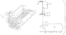
- FIG. 1is a perspective view of a preferred embodiment of a front piece attached to a front segment of a track device according to the present invention.
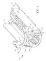
- FIG. 2is a side view of the track device of FIG. 1 .
- FIG. 3is a side view similar to FIG. 2 but showing the front piece detached from the front segment.
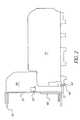
- FIG. 4is a front view of the front piece of FIG. 1 .
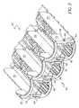
- FIG. 5is a perspective view of another preferred embodiment of a front piece attached to a multi-channel front segment of a track device according to the present invention.
- FIG. 6is a front view of the front piece of FIG. 5 .
- a display rack unit assembled from multiple track devicesis designed to merchandise articles such as bottled or canned drink products.
- the display rack unitincludes a plurality of elongated track devices interconnected in side-by-side relationship.
- the number of track devices used to assemble the display rack unitis determined such that the size of the unit is suitable for placement onto an existing display shelf in a retail environment.
- Adjacent tracksmay be formed as a single unit, or the interconnection of two adjacent track devices may be achieved by connecting means such as connector slots cooperating horizontal connector elements.
- Track devices and connector elementsare more fully described in U.S. Pat. No. 5,634,564, which issued Jun. 3, 1997 to Spamer et al., the disclosure of which is incorporated herein by reference.
- Front panel assembly 10for an elongated display track device 12 .
- Display track device 12is composed of a number of sections or segments that are frangibly connected end-to-end to one another. Such track devices are more fully described in co-pending application Ser. No. 09/999,317 filed Oct. 31, 2001,now U.S. Pat. No. 6,615,995, the disclosure of which is incorporated herein by reference.
- Front panel assembly 10is preferably a unitary structure constructed of plastic using an injection molding process, but may be constructed of other materials.
- a front track segment of track device 12has a floor or base wall with opposed upstanding sidewalls 14 , 16 forming a channel for a single row of articles to slide along between the sidewalls 14 , 16 .
- the front track segmenthas a front end portion that will be disposed at the front of the display shelf and a rear end portion that defines a keyway or other means for connecting to an intermediate track segment or a rear track segment.
- the right sidewall panel 14defines a notch 18 and an upstanding protrusion or arm 20 .
- the front track segmentdefines a slot 15 below right sidewall panel 14 .
- the slot 15is preferably formed of a three sided loop of material attached to the base wall to accept a member forced into it.
- the left sidewall panel 16defines a notch 22 and an upstanding protrusion or arm 24 .
- the front track segmentdefines a slot 17 below left sidewall panel 16 similar to the slot below the right sidewall panel.
- the front panel assembly 10has a base member with a front edge that is preferably curved or contoured to fit the contour of a beverage container.
- Front panel assembly 10is illustrated as having first and second upstanding sidewalls 26 , 30 with adjacent sidewalls forming partitions to hold a row of beverage containers therebetween. There may be as few as two sidewalls to accommodate a single row of beverage containers (FIG. 4) or as many sidewalls as are necessary for multiple rows to fill the width of a refrigerator unit (FIG. 5 ).
- Each sidewallhas a top end portion, a bottom end portion, and a front edge that extends between the top and bottom end portions of the sidewall.
- each sidewallhas a protrusion formed 30 on a rear portion thereof for resting in one of the notches 18 , 22 to help marry the front panel to the front segment of the track device 12 .
- Each sidewall 26 , 30has a slot or opening to receive one of the upstanding arms 20 , 24 therein to help marry the front panel to the front segment of the track device 12 .
- the first sidewall 26is connected along its bottom end portion to the base.
- Second sidewall 30is laterally spaced from first sidewall 16 and is connected along its bottom end portion to the base. Ideally, the lateral spacing between the first and second sidewalls 26 , 30 is slightly greater than the width of the beverage container to be displayed between the sidewalls to allow easy movement of the beverage container while preventing it from tilting askew.
- a first face member 34has a top end portion and a bottom end portion and is connected to the front edge of the first sidewall 26 . Face member 34 extends laterally a preselected distance from first sidewall 26 toward second sidewall 30 . Face member 34 extends a distance sufficient to interfere with a beverage container to thereby restrain the container from moving forward in the rack.
- a second face member 36has a top end portion and a bottom end portion and is connected the front edge of second sidewall 30 . Second face member 36 extends a preselected distance from second sidewall 30 toward first sidewall 26 . Face members 34 , 36 are preferably connected to base 12 but have sufficient structural integrity when only connected to the sidewalls 26 , 30 .
- an elongated connecting member 38has a first end connected to the top end portion of first face member 34 and has a second end portion connected to the top end portion of second face member 36 .
- connecting member 38may be attached to both the face members and sidewalls for the strongest bond.
- Connecting member 38curves outward away from face members 34 and 36 , and is shaped to fit the contour of a beverage container in the rack. It extends outward over the curved portion of the base wall.
- Connecting member 38 , face members 34 and 36 , and the baseform a viewing window through which the label of a beverage container can be viewed prior to selection of a beverage from the rack.
- a first downwardly extending finger 40fits into the slot below front segment right sidewall panel 14 .
- Finger 40has a rearwardly projecting protrusion 42 positioned to engage the underside of the base wall forming a latch that holds the front panel and front segment together.
- a corner of the finger 40 opposite projecting protrusion 42may be truncated so that the finger can fit through the slot and snap into latching contact with the base member.
- a second downwardly extending finger 44fits into the slot below front segment left sidewall panel 16 .
- Finger 44has a rearwardly projecting protrusion 46 positioned to engage the underside of the base wall forming a latch that holds the front panel and front segment together.
- a first front stop member 48extends laterally a preselected distance from the first sidewall 26 toward the second sidewall 30
- a second front stop member 50extends laterally a preselected distance from the second sidewall 30 toward the first sidewall 26 .
- First stop member 48is shorter than face member 34 and is preferably connected to face member 34 but may be attached to sidewall 26 or to the base wall.
- Second stop member 50is shorter than face member 36 and is preferably connected to face member 36 but may be attached to sidewall 30 or to the base wall.
- the base, face members, connecting member and front stop membersdefine a viewing window for the display track device.
- a front track segment of track device 52has a floor or base wall with parallel upstanding sidewalls 53 , 54 , 55 , 56 , in this example, forming a three channels, each for a single row of articles to slide along between adjacent sidewalls.
- Each sidewall paneldefines a notch 58 and an upstanding protrusion or arm 60 .
- the front track segmentdefines a slot below each sidewall panel. The slot is preferably formed of a three sided loop of material attached to the base wall to accept a member forced into it.
- the front panel assembly 62has a base member with a front edge that is preferably curved or contoured to fit the contour of a beverage container.
- Front panel assembly 62is illustrated as having four upstanding sidewalls 64 , 66 , 68 , 70 with adjacent sidewalls forming partitions to hold a row of beverage containers therebetween.
- the sidewallsmay be separate with several channels joined together or may be integrally formed with adjacent channels sharing a common sidewall.
- Each sidewallhas a top end portion, a bottom end portion, and a front edge that extends between the top and bottom end portions of the sidewall.
- each sidewallhas a protrusion 72 formed on a rear portion thereof for resting in the notch 58 to help marry the front panel to the front segment of the track device.
- Each sidewallhas a slot or opening to receive one of the upstanding arms 60 therein to help marry the front panel 62 to the front segment of the track device 48 .
- the first sidewall 64 of the front panel assembly 62is connected along its bottom end portion to the base wall.
- Second sidewall 66is laterally spaced from first sidewall 64 and is connected along its bottom end portion to the base wall. Ideally, the lateral spacing between the first and second sidewalls 64 , 66 is slightly greater than the width of the beverage container to be displayed between the sidewalls to allow easy movement of the beverage container while preventing it from tilting askew.
- Third sidewall 68is similarly laterally spaced from second sidewall 66 and fourth sidewall 70 .
- Second sidewall 66lies intermediate first and third sidewall 64 , 68
- third sidewall 68lies intermediate second and fourth sidewalls 66 , 70 .
- a first face member 74has a top end portion and a bottom end portion and is connected to the front edge of the first sidewall 64 . Face ember 74 extends laterally a preselected distance from first sidewall 64 toward second sidewall 66 .
- a second face member 76is connected to the front edge of second sidewall 66 .
- Second face member 36extends from second sidewall 66 toward first sidewall 64 .
- a third face member 78is connected to second sidewall 66 adjacent second face member 76 .
- Third face member 78extends from second sidewall 66 toward third sidewall 68 .
- a fourth face member 80is connected to third sidewall 68 adjacent a fifth face member 82 .
- Fourth face member 80extends from third sidewall 68 toward second sidewall 66 .
- Fifth face member 82extends from third sidewall 68 toward fourth sidewall 70 and sixth face member 84 .
- the face membersare preferably connected to the base wall but have sufficient structural integrity when only connected to the sidewalls.
- a first elongated connecting member 86has a first end connected to the top end portion of first face member 74 and has a second end portion connected to the top end portion of second face member 76 .
- Connecting member 86curves outward away from face members 74 and 76 , and is shaped to fit the contour of a beverage container in the rack. It extends outward over the curved portion of the base wall.
- First connecting member 86 , face members 74 and 76 , and the baseform a viewing window through which the label of a beverage container can be viewed prior to selection of a beverage from the rack.
- a second elongated connecting member 88has its ends connected to the top end portions of third and fourth face members 78 and 80 .
- a third elongated connecting member 90has its ends connected to the top end portions of fifth and sixth face members 82 and 80 .
- Downwardly extending fingers 92fit into slots below the front segment sidewall panels.
- the number of fingersis preferably equal to the number of face embers.
- Each finger 92has a rearwardly projecting protrusion positioned to engage the underside of the base wall forming a latch that holds the front panel and front segment together. A corner of the finger opposite the projecting protrusion is truncated so that the fingers can fit through the slots more easily.
- a first front stop member 94extends laterally a preselected distance from the first sidewall 64 toward the second sidewall 66
- a second front stop member 96extends laterally a preselected distance from the second sidewall 66 toward the first sidewall 64 .
- First stop member 94is shorter than its associated face member 74 and is preferably connected to face member 74 but may be attached to sidewall 64 or to the base wall.
- Second stop member 96is shorter than face member 76 and is preferably connected to face member 76 but may be attached to sidewall 66 or to the base wall.
- the base, face members 74 , 76 , connecting member 86 and front stop members 94 , 96define a first viewing window for the display track device.
- the base, face members 78 , 80 , connecting member 88 and front stop members 98 , 100define a second viewing window adjacent the first viewing window.
- the base, face members 82 , 84 , connecting member 90 and front stop members 102 , 104define a third viewing window adjacent the second viewing window.
- a front panel assembly for a display track devicehas been presented.
- a front panel for a display rackhas a base with first and second upstanding sidewalls attached to the base. The sidewalls are connected along their bottom ends to the base.
- a first face memberis connected to the first sidewall and extends laterally toward the second sidewall.
- a second face memberis connected to the second sidewall and extends laterally toward the first sidewall.
- An elongate connecting memberis connect to the tops of the first and second face members.
- a first front stop memberis connected to the first face member and extends laterally a preselected distance from the first sidewall toward the second sidewall.
- a second front stop memberis connected to the second face member and extends laterally a preselected distance from the second sidewall toward the first sidewall.
- the base, face members, stop members and connecting memberdefine the viewing window for the display track device.
- the front panel assemblyis attached to the front segment using fingers depending from the front panel that engage slots formed on the front segment. It virtually snaps into position on the rack.
- the front panelholds a beverage container in position, first for viewing, and then for selection and removal from the rack by a consumer.
- the containeris held upright and forward in the track so that a container is always ready for removal from the rack.
- the contour of the front panelallows the beverage container to fit forward in the track.
- a front piece for a multi-channel unitmay be a unitary structure or may be several individual front pieces connected using depending gingers to fit into openings in the track device, and may receive arms of the track device into openings to connected the track device and front piece.
Landscapes
- Freezers Or Refrigerated Showcases (AREA)
Abstract
Description
This invention relates generally to a adjustable length track device for a merchandising display shelf, and, more particularly, to a front piece for such a track device.
Display racks are used to shelve merchandise awaiting purchase by a consumer. Some items, such as beverages, are best when consumed chilled, and are consequently shelved in a refrigerator. Display racks are used in the refrigerator to keep beverage containers upright for easy viewing and to separate them for dispensing one at a time. Beverages are removed one at a time from the front of the rack and the remaining inventory is urged to the front of the rack by gravity or a pusher mechanism. Restocking conveniently occurs from the rear of the rack ensuring that beverages are chilled when they reach the front of the rack. The front of the rack is important for presentation of the beverage. Accordingly, it will be appreciated that it would be highly desirable to have a display rack that promotes easy dispensing of beverage containers and promotes easy viewing of beverage container labeling.
A display rack unit is assembled from multiple track devices for merchandising articles such as bottled on canned drink products. The display rack unit includes a plurality of elongated track devices interconnected, often detachably interconnected, in side-by-side relationship. The number of track devices used to assemble the display rack unit is determined such that the size of the unit is suitable for placement onto an existing display shelf in a retail environment to fill the width of the shelf.
Track devices require a stop member on the front which is referred to as a front piece. An ideal front piece stops the forward motion of the articles to prevent inadvertent removal while allowing intentional removal by a purchaser, and provides a window for easily viewing the product label. A problem with the front piece is attaching it to the body of the display shelf. Some front pieces are integrally formed with the body as a single unit, but the intricate molds required increase manufacturing complexity and cost. Detachable font pieces present a problem also because it sometimes breaks or becomes deformed while being installed due to complicated fastening mechanisms. It will be appreciated that it would be highly desirable to have an adjustable track device with a front piece that is easy to attach and detach.
The present invention is directed to overcoming one or more of the problems set forth above. Briefly summarized, according to one aspect of the present invention, a front panel for a display rack comprises a base, upstanding sidewalls connected along their bottom end portions to the base, face members connected to the front edges of the sidewalls, and an elongate connecting member connected to the top end portions of the face members. The base, face members and connecting member define a viewing window for the display rack through which a beverage container in a display rack in a refrigerator can be viewed. The base and connecting member curve outward to position a beverage container forward in the display rack for easy removal. A pair of downwardly extending fingers slip into receiving slots in the front segment to fasten the front panel to the front segment of the display rack.
These and other aspects, objects, features and advantages of the present invention will be more clearly understood and appreciated from a review of the following detailed description of the preferred embodiments and appended claims, and by reference to the accompanying drawings
FIG. 1 is a perspective view of a preferred embodiment of a front piece attached to a front segment of a track device according to the present invention.
FIG. 2 is a side view of the track device of FIG.1.
FIG. 3 is a side view similar to FIG. 2 but showing the front piece detached from the front segment.
FIG. 4 is a front view of the front piece of FIG.1.
FIG. 5 is a perspective view of another preferred embodiment of a front piece attached to a multi-channel front segment of a track device according to the present invention.
FIG. 6 is a front view of the front piece of FIG.5.
Referring to FIGS. 1-5, a display rack unit assembled from multiple track devices is designed to merchandise articles such as bottled or canned drink products. The display rack unit includes a plurality of elongated track devices interconnected in side-by-side relationship. The number of track devices used to assemble the display rack unit is determined such that the size of the unit is suitable for placement onto an existing display shelf in a retail environment. Adjacent tracks may be formed as a single unit, or the interconnection of two adjacent track devices may be achieved by connecting means such as connector slots cooperating horizontal connector elements. Track devices and connector elements are more fully described in U.S. Pat. No. 5,634,564, which issued Jun. 3, 1997 to Spamer et al., the disclosure of which is incorporated herein by reference.
Referring to FIGS. 1-4, there is illustrated afront panel assembly 10 for an elongateddisplay track device 12.Display track device 12 is composed of a number of sections or segments that are frangibly connected end-to-end to one another. Such track devices are more fully described in co-pending application Ser. No. 09/999,317 filed Oct. 31, 2001,now U.S. Pat. No. 6,615,995, the disclosure of which is incorporated herein by reference.Front panel assembly 10 is preferably a unitary structure constructed of plastic using an injection molding process, but may be constructed of other materials.
A front track segment oftrack device 12 has a floor or base wall with opposedupstanding sidewalls sidewalls right sidewall panel 14 defines anotch 18 and an upstanding protrusion orarm 20. The front track segment defines aslot 15 belowright sidewall panel 14. Theslot 15 is preferably formed of a three sided loop of material attached to the base wall to accept a member forced into it. Similarly, theleft sidewall panel 16 defines anotch 22 and an upstanding protrusion orarm 24. The front track segment defines a slot17 belowleft sidewall panel 16 similar to the slot below the right sidewall panel.
Thefront panel assembly 10 has a base member with a front edge that is preferably curved or contoured to fit the contour of a beverage container.Front panel assembly 10 is illustrated as having first and secondupstanding sidewalls notches track device 12. Eachsidewall upstanding arms track device 12.
Thefirst sidewall 26 is connected along its bottom end portion to the base.Second sidewall 30 is laterally spaced fromfirst sidewall 16 and is connected along its bottom end portion to the base. Ideally, the lateral spacing between the first andsecond sidewalls
Afirst face member 34 has a top end portion and a bottom end portion and is connected to the front edge of thefirst sidewall 26.Face member 34 extends laterally a preselected distance fromfirst sidewall 26 towardsecond sidewall 30.Face member 34 extends a distance sufficient to interfere with a beverage container to thereby restrain the container from moving forward in the rack.
Asecond face member 36 has a top end portion and a bottom end portion and is connected the front edge ofsecond sidewall 30.Second face member 36 extends a preselected distance fromsecond sidewall 30 towardfirst sidewall 26.Face members sidewalls
Still referring to FIG. 1, an elongated connectingmember 38 has a first end connected to the top end portion offirst face member 34 and has a second end portion connected to the top end portion ofsecond face member 36. By attaching the elongated connectingmember 38 to facemembers member 38 may be attached to both the face members and sidewalls for the strongest bond. Connectingmember 38 curves outward away fromface members member 38,face members
A first downwardly extendingfinger 40 fits into the slot below front segmentright sidewall panel 14.Finger 40 has a rearwardly projectingprotrusion 42 positioned to engage the underside of the base wall forming a latch that holds the front panel and front segment together. Where the slot is rigid instead of resilient, a corner of thefinger 40 opposite projectingprotrusion 42 may be truncated so that the finger can fit through the slot and snap into latching contact with the base member. Similarly, a second downwardly extendingfinger 44 fits into the slot below front segment leftsidewall panel 16.Finger 44 has a rearwardly projecting protrusion46 positioned to engage the underside of the base wall forming a latch that holds the front panel and front segment together.
A firstfront stop member 48 extends laterally a preselected distance from thefirst sidewall 26 toward thesecond sidewall 30, and a secondfront stop member 50 extends laterally a preselected distance from thesecond sidewall 30 toward thefirst sidewall 26.First stop member 48 is shorter thanface member 34 and is preferably connected to facemember 34 but may be attached to sidewall26 or to the base wall.Second stop member 50 is shorter thanface member 36 and is preferably connected to facemember 36 but may be attached to sidewall30 or to the base wall. The base, face members, connecting member and front stop members define a viewing window for the display track device.
Referring to FIGS. 5 and 6, a front track segment oftrack device 52 has a floor or base wall with parallelupstanding sidewalls notch 58 and an upstanding protrusion orarm 60. The front track segment defines a slot below each sidewall panel. The slot is preferably formed of a three sided loop of material attached to the base wall to accept a member forced into it.
Thefront panel assembly 62 has a base member with a front edge that is preferably curved or contoured to fit the contour of a beverage container.Front panel assembly 62 is illustrated as having fourupstanding sidewalls protrusion 72 formed on a rear portion thereof for resting in thenotch 58 to help marry the front panel to the front segment of the track device. Each sidewall has a slot or opening to receive one of theupstanding arms 60 therein to help marry thefront panel 62 to the front segment of thetrack device 48.
Thefirst sidewall 64 of thefront panel assembly 62 is connected along its bottom end portion to the base wall.Second sidewall 66 is laterally spaced fromfirst sidewall 64 and is connected along its bottom end portion to the base wall. Ideally, the lateral spacing between the first andsecond sidewalls Third sidewall 68 is similarly laterally spaced fromsecond sidewall 66 andfourth sidewall 70.Second sidewall 66 lies intermediate first andthird sidewall third sidewall 68 lies intermediate second andfourth sidewalls
Afirst face member 74 has a top end portion and a bottom end portion and is connected to the front edge of thefirst sidewall 64.Face ember 74 extends laterally a preselected distance fromfirst sidewall 64 towardsecond sidewall 66. Asecond face member 76 is connected to the front edge ofsecond sidewall 66.Second face member 36 extends fromsecond sidewall 66 towardfirst sidewall 64. Athird face member 78 is connected tosecond sidewall 66 adjacentsecond face member 76.Third face member 78 extends fromsecond sidewall 66 towardthird sidewall 68. Afourth face member 80 is connected tothird sidewall 68 adjacent afifth face member 82.Fourth face member 80 extends fromthird sidewall 68 towardsecond sidewall 66.Fifth face member 82 extends fromthird sidewall 68 towardfourth sidewall 70 andsixth face member 84. The face members are preferably connected to the base wall but have sufficient structural integrity when only connected to the sidewalls.
A first elongated connectingmember 86 has a first end connected to the top end portion offirst face member 74 and has a second end portion connected to the top end portion ofsecond face member 76. Connectingmember 86 curves outward away fromface members member 86,face members member 88 has its ends connected to the top end portions of third andfourth face members member 90 has its ends connected to the top end portions of fifth andsixth face members
Downwardly extendingfingers 92 fit into slots below the front segment sidewall panels. The number of fingers is preferably equal to the number of face embers. Eachfinger 92 has a rearwardly projecting protrusion positioned to engage the underside of the base wall forming a latch that holds the front panel and front segment together. A corner of the finger opposite the projecting protrusion is truncated so that the fingers can fit through the slots more easily.
A firstfront stop member 94 extends laterally a preselected distance from thefirst sidewall 64 toward thesecond sidewall 66, and a secondfront stop member 96 extends laterally a preselected distance from thesecond sidewall 66 toward thefirst sidewall 64.First stop member 94 is shorter than its associatedface member 74 and is preferably connected to facemember 74 but may be attached to sidewall64 or to the base wall.Second stop member 96 is shorter thanface member 76 and is preferably connected to facemember 76 but may be attached to sidewall66 or to the base wall. The base,face members member 86 andfront stop members face members member 88 andfront stop members face members member 90 andfront stop members
It can now be appreciated that a front panel assembly for a display track device has been presented. A front panel for a display rack has a base with first and second upstanding sidewalls attached to the base. The sidewalls are connected along their bottom ends to the base. A first face member is connected to the first sidewall and extends laterally toward the second sidewall. A second face member is connected to the second sidewall and extends laterally toward the first sidewall. An elongate connecting member is connect to the tops of the first and second face members. A first front stop member is connected to the first face member and extends laterally a preselected distance from the first sidewall toward the second sidewall. A second front stop member is connected to the second face member and extends laterally a preselected distance from the second sidewall toward the first sidewall. The base, face members, stop members and connecting member define the viewing window for the display track device.
The front panel assembly is attached to the front segment using fingers depending from the front panel that engage slots formed on the front segment. It virtually snaps into position on the rack. The front panel holds a beverage container in position, first for viewing, and then for selection and removal from the rack by a consumer. The container is held upright and forward in the track so that a container is always ready for removal from the rack. The contour of the front panel allows the beverage container to fit forward in the track.
While the invention has been described with particular reference to the preferred embodiments, it will be understood by those skilled in the art that various changes may be made and equivalents may be substituted for elements of the preferred embodiments without departing from invention. For example, a front piece for a multi-channel unit may be a unitary structure or may be several individual front pieces connected using depending gingers to fit into openings in the track device, and may receive arms of the track device into openings to connected the track device and front piece.
As is evident from the foregoing description, certain aspects of the invention are not limited to the particular details of the examples illustrated, and it is therefore contemplated that other modifications and applications will occur to those skilled in the art. For example, the lateral dimensions of the face members may be increased to accommodate narrower containers. It is accordingly intended that the claims shall cover all such modifications and applications as do not depart from the true spirit and scope of the invention.
Claims (11)
1. A front panel for a display rack, said display rack having a front segment defining first and second slots disposed substantially adjacent a lower forward edge thereof, said front panel comprising:
a base;
a first upstanding sidewall having a top end portion, a bottom end portion and a front edge, said first sidewall being connected along a bottom end portion to said base;
a second upstanding sidewall having a top end portion, a bottom end portion and a front edge, said second sidewall being laterally spaced from said first sidewall and connected along a bottom end portion to said base;
a first face member having a top end portion and a bottom end portion and being connected to said front edge of said first sidewall, said first face member extending laterally a preselected distance from said first sidewall toward said second sidewall;
a second face member having a top end portion and a bottom end portion and being connected to said front edge of said second sidewall, said second face member extending laterally a preselected distance from said second sidewall toward said first sidewall;
an elongate connecting member having a first end connected to said top end portion of said first face member and a second end portion connected to said top end portion of said second face member;
a first finger attached substantially adjacent a lower forward edge of one of said first sidewall and said base and extending downwardly therefrom, said first finger adapted to fit in said first slot to thereby fasten said front panel to said front segment; and
a second finger attached substantially adjacent a lower forward edge of one of said second sidewall and said base and extending downwardly therefrom, said second finger being laterally spaced from said first finger and adapted to fit in said second slot to thereby fasten said front panel to said front segment.
2. A front panel, as set forth inclaim 1 , including:
a first front stop member extending laterally a preselected distance from said first face member toward said second sidewall; and
a second front stop member extending laterally a preselected distance from said second face member toward said first sidewall.
3. A front panel, as set forth inclaim 2 , wherein said base, face members, connecting member and front stop members define a viewing window for said display rack.
4. A front panel, as set forth inclaim 2 , wherein said first front stop member is attached to said base.
5. A front panel, as set forth inclaim 1 , wherein said elongate connecting member curves outward away from said face members.
6. A front panel assembly for a display rack, said display rack having a front segment defining at least first and second slots disposed substantially adjacent a lower forward edge thereof, said front panel comprising:
a base;
a first upstanding sidewall having a top end portion, a bottom end portion and a front edge, said first sidewall being connected along a bottom end portion to said base;
a second upstanding sidewall having a top end portion, a bottom end portion and a front edge, said second sidewall being laterally spaced from said first sidewall and connected along bottom end portion to said base;
a third upstanding sidewall having a top end portion, a bottom end portion and a front edge, said third sidewall being laterally spaced from said second sidewall and connected along a bottom end portion to said base, said second sidewall being intermediate said first and third sidewalls;
a first face member having a top end portion and a bottom end portion and being connected to said front edge of said first sidewall, said first face member extending laterally a preselected distance from said first sidewall toward said second sidewall;
a second face member having a top end portion and a bottom end portion and being connected to said front edge of said second sidewall, said second face member extending laterally a preselected distance from said second sidewall toward said first sidewall and extending laterally a preselected distance from said second sidewall toward said third sidewall;
a third face member having a top end portion and a bottom end portion and being connected to said front edge of said third sidewall, said third face member extending laterally a preselected distance from said third sidewall toward said second sidewall;
a first elongate connecting member having a first end connected to said top end portion of said first face member and a second end portion connected to said top end portion of said second face member, said base, face members and connecting member defining a first viewing window for said display rack;
a second elongate connecting member having a first end connected to said top end portion of said second face member and a second end portion connected to said top end portion of said third face member, said base, face members and connecting member defining a second viewing window for said display rack; and
at least first and second fingers, said first finger being attached substantially adjacent a lower forward edge of one of said base and first, second and third sidewalls, said first finger extending downwardly therefrom, said first finger being adapted to fit in said first slot to thereby fasten said front panel to said front segment, said second finger being attached substantially adjacent a lower forward edge of one of said base and first, second and third sidewalls, said second finger extending downwardly therefrom and being laterally spaced from said first finger, said second finger being adapted to fit in said second slot to thereby fasten said front panel to said front segment.
7. A front panel, as set forth inclaim 6 , including:
a first front stop member extending laterally a preselected distance from said first face member toward said second sidewall; and
a second front stop member extending laterally a preselected distance from said second face member toward said first sidewall;
a third front stop member extending laterally a preselected distance from said third face member toward said third sidewall; and
a fourth front stop member extending laterally a preselected distance from said fourth face member toward said second sidewall.
8. A front panel, as set forth inclaim 7 , wherein said base, first and second face members, first connecting member and first and second front stop members define a first viewing window for said display rack.
9. A front panel, as set forth inclaim 7 , wherein said base, second and third face members, second connecting member and third and fourth front stop members define a second viewing window for said display rack.
10. A front panel, as set forth inclaim 7 , wherein said front stop members are attached to said base.
11. A front panel, as set forth inclaim 6 , wherein said elongate connecting members curve outward away from said face members.
Priority Applications (1)
| Application Number | Priority Date | Filing Date | Title |
|---|---|---|---|
| US10/207,319US6679389B1 (en) | 2002-07-29 | 2002-07-29 | Front piece for a merchandising display track device |
Applications Claiming Priority (1)
| Application Number | Priority Date | Filing Date | Title |
|---|---|---|---|
| US10/207,319US6679389B1 (en) | 2002-07-29 | 2002-07-29 | Front piece for a merchandising display track device |
Publications (1)
| Publication Number | Publication Date |
|---|---|
| US6679389B1true US6679389B1 (en) | 2004-01-20 |
Family
ID=30000136
Family Applications (1)
| Application Number | Title | Priority Date | Filing Date |
|---|---|---|---|
| US10/207,319Expired - Fee RelatedUS6679389B1 (en) | 2002-07-29 | 2002-07-29 | Front piece for a merchandising display track device |
Country Status (1)
| Country | Link |
|---|---|
| US (1) | US6679389B1 (en) |
Cited By (39)
| Publication number | Priority date | Publication date | Assignee | Title |
|---|---|---|---|---|
| US20040084391A1 (en)* | 2002-10-31 | 2004-05-06 | Bernard Primiano | Display track device with anti-torsion bar |
| US20070080166A1 (en)* | 2005-10-12 | 2007-04-12 | Rtc Industries, Inc. | Cylindrical container dispenser |
| US20070251996A1 (en)* | 2006-04-26 | 2007-11-01 | Dimitri Kanevsky | Verification of a biometric identification |
| US20070256992A1 (en)* | 2006-05-04 | 2007-11-08 | Carl Olson | Shelf divider system |
| US20080121595A1 (en)* | 2006-11-28 | 2008-05-29 | Trulaske Steven L | Shelf Organizer |
| US20080129161A1 (en)* | 2006-10-23 | 2008-06-05 | Rtc Industries, Inc. | Merchandising System with Flippable Column and/or Item Stop |
| US20080223804A1 (en)* | 2007-03-14 | 2008-09-18 | Riley Daniel C | Display rack with ventilation window in the vertical walls |
| US7823734B2 (en) | 2005-09-12 | 2010-11-02 | Rtc Industries, Inc. | Product management display system with trackless pusher mechanism |
| US20110094980A1 (en)* | 2009-10-23 | 2011-04-28 | Cousin Serge L | Display channel apparatus |
| US8312999B2 (en) | 2005-09-12 | 2012-11-20 | Rtc Industries, Inc. | Product management display system with trackless pusher mechanism |
| US20130031815A1 (en)* | 2005-09-12 | 2013-02-07 | Rtc Industries Inc. | Product Management Display System with Trackless Pusher Mechanism |
| US8453850B2 (en) | 2005-09-12 | 2013-06-04 | Rtc Industries, Inc. | Product management display system with trackless pusher mechanism |
| US8739984B2 (en) | 2005-09-12 | 2014-06-03 | Rtc Industries, Inc. | Product management display system with trackless pusher mechanism |
| US20140175032A1 (en)* | 2012-12-20 | 2014-06-26 | Hon Hai Precision Industry Co., Ltd. | Mounting apparatus for goods channel |
| US8967394B2 (en) | 2005-09-12 | 2015-03-03 | Rtc Industries, Inc. | Product management display system with trackless pusher mechanism |
| US8978904B2 (en) | 2005-09-12 | 2015-03-17 | Rtc Industries, Inc. | Product management display system with trackless pusher mechanism |
| US9060624B2 (en) | 2005-09-12 | 2015-06-23 | Rtc Industries, Inc. | Product management display system with rail mounting clip |
| US20150208830A1 (en)* | 2014-01-24 | 2015-07-30 | Rtc Industries, Inc. | Product management display system |
| US9138075B2 (en) | 2005-09-12 | 2015-09-22 | Rtc Industries, Inc. | Product management display system |
| US9173504B2 (en) | 2005-09-12 | 2015-11-03 | Rtc Industries, Inc. | Product management display system |
| US9232864B2 (en) | 2005-09-12 | 2016-01-12 | RTC Industries, Incorporated | Product management display system with trackless pusher mechanism |
| US9259102B2 (en) | 2005-09-12 | 2016-02-16 | RTC Industries, Incorporated | Product management display system with trackless pusher mechanism |
| US9265362B2 (en) | 2005-09-12 | 2016-02-23 | RTC Industries, Incorporated | Product management display system |
| US9265358B2 (en) | 2005-09-12 | 2016-02-23 | RTC Industries, Incorporated | Product management display system |
| US9486088B2 (en) | 2005-09-12 | 2016-11-08 | Rtc Industries, Inc. | Product management display system |
| US9750354B2 (en) | 2005-09-12 | 2017-09-05 | Rtc Industries, Inc. | Product management display system |
| USD801734S1 (en) | 2014-12-01 | 2017-11-07 | Retail Space Solutions Llc | Shelf management parts |
| US9955802B2 (en) | 2015-04-08 | 2018-05-01 | Fasteners For Retail, Inc. | Divider with selectively securable track assembly |
| US10154739B2 (en) | 2013-12-02 | 2018-12-18 | Retail Space Solutions Llc | Universal merchandiser and methods relating to same |
| US10178909B2 (en) | 2016-01-13 | 2019-01-15 | Rtc Industries, Inc. | Anti-splay device for merchandise display system |
| US10285510B2 (en) | 2005-09-12 | 2019-05-14 | Rtc Industries, Inc. | Product management display system |
| US10368657B2 (en) | 2014-09-26 | 2019-08-06 | Eva Lilja | Channel glide assemblies |
| US10448756B2 (en) | 2017-06-16 | 2019-10-22 | Rtc Industries, Inc. | Product management display system with trackless pusher mechanism |
| US10952546B2 (en) | 2005-09-12 | 2021-03-23 | Rtc Industries, Inc. | Product management display system with trackless pusher mechanism |
| US10959540B2 (en) | 2016-12-05 | 2021-03-30 | Retail Space Solutions Llc | Shelf management system, components thereof, and related methods |
| US11045017B2 (en) | 2017-04-27 | 2021-06-29 | Retail Space Solutions Llc | Shelf-mounted tray and methods relating to same |
| US11259652B2 (en) | 2005-09-12 | 2022-03-01 | Rtc Industries, Inc. | Product management display system |
| US11344138B2 (en) | 2005-09-12 | 2022-05-31 | Rtc Industries, Inc. | Product management display system |
| US11583109B2 (en) | 2005-09-12 | 2023-02-21 | Rtc Industries, Inc. | Product management display system with trackless pusher mechanism |
Citations (18)
| Publication number | Priority date | Publication date | Assignee | Title |
|---|---|---|---|---|
| US4598828A (en)* | 1983-02-22 | 1986-07-08 | Visual Marketing, Inc. | Storage and dispensing rack |
| US5240126A (en)* | 1992-05-29 | 1993-08-31 | The Gillette Company | Dispensing rack apparatus |
| US5531336A (en)* | 1994-03-11 | 1996-07-02 | The Mead Corporation | Device for stabilizing containers in a gravity feed tray |
| US5645176A (en)* | 1996-08-08 | 1997-07-08 | Display Technologies, Inc. | Display rack with channel front member |
| US5665304A (en)* | 1995-12-12 | 1997-09-09 | Warner-Lambert Company | Display unit |
| US5685664A (en)* | 1995-06-13 | 1997-11-11 | The Mead Corporation | Arrangement for interconnecting two objects |
| US5695074A (en)* | 1995-10-10 | 1997-12-09 | Henschel-Steinau, Inc. | Gravity feed bottle display and dispensing rack |
| US5706957A (en)* | 1996-03-18 | 1998-01-13 | Rtc Industries, Inc. | Gravity feed track system |
| US5788091A (en)* | 1996-02-16 | 1998-08-04 | The Mead Corporation | Article-dispensing system having an attraction device |
| US5971204A (en)* | 1997-10-17 | 1999-10-26 | Rehrig Pacific Company | Bottle dispenser |
| US6068139A (en)* | 1998-06-19 | 2000-05-30 | American Greetings Corporation | Retail product display system |
| US6068142A (en)* | 1999-05-27 | 2000-05-30 | Display Industries, Llc | Front panel for a display rack |
| US6082556A (en)* | 1998-05-07 | 2000-07-04 | Display Industries Llc | Merchandising display track device having attached front wall |
| US6142316A (en)* | 1997-10-08 | 2000-11-07 | Paul Flum Ideas, Inc. | Product merchandising display unit with replaceable product graphics |
| US6189734B1 (en)* | 1996-11-18 | 2001-02-20 | Rehrig Pacific Company | Merchandise dispensing device |
| US6237784B1 (en)* | 1999-12-06 | 2001-05-29 | Display Industries, Llc. | Label orienting display rack |
| US20010002658A1 (en)* | 1997-11-08 | 2001-06-07 | Mark Higgins | Merchandising display track device of multiple-piece construction |
| US20010020606A1 (en)* | 1997-10-10 | 2001-09-13 | L&P Property Management Company | Shelf assembly |
- 2002
- 2002-07-29USUS10/207,319patent/US6679389B1/ennot_activeExpired - Fee Related
Patent Citations (20)
| Publication number | Priority date | Publication date | Assignee | Title |
|---|---|---|---|---|
| US4598828A (en)* | 1983-02-22 | 1986-07-08 | Visual Marketing, Inc. | Storage and dispensing rack |
| US5240126A (en)* | 1992-05-29 | 1993-08-31 | The Gillette Company | Dispensing rack apparatus |
| US5531336A (en)* | 1994-03-11 | 1996-07-02 | The Mead Corporation | Device for stabilizing containers in a gravity feed tray |
| US5685664A (en)* | 1995-06-13 | 1997-11-11 | The Mead Corporation | Arrangement for interconnecting two objects |
| US5695074A (en)* | 1995-10-10 | 1997-12-09 | Henschel-Steinau, Inc. | Gravity feed bottle display and dispensing rack |
| US5665304A (en)* | 1995-12-12 | 1997-09-09 | Warner-Lambert Company | Display unit |
| US5788091A (en)* | 1996-02-16 | 1998-08-04 | The Mead Corporation | Article-dispensing system having an attraction device |
| US5706957A (en)* | 1996-03-18 | 1998-01-13 | Rtc Industries, Inc. | Gravity feed track system |
| US5645176A (en)* | 1996-08-08 | 1997-07-08 | Display Technologies, Inc. | Display rack with channel front member |
| US6189734B1 (en)* | 1996-11-18 | 2001-02-20 | Rehrig Pacific Company | Merchandise dispensing device |
| US6142316A (en)* | 1997-10-08 | 2000-11-07 | Paul Flum Ideas, Inc. | Product merchandising display unit with replaceable product graphics |
| US20010020606A1 (en)* | 1997-10-10 | 2001-09-13 | L&P Property Management Company | Shelf assembly |
| US6513667B2 (en)* | 1997-10-10 | 2003-02-04 | L&P Property Management Company | Shelf assembly having product holders |
| US5971204A (en)* | 1997-10-17 | 1999-10-26 | Rehrig Pacific Company | Bottle dispenser |
| US6325221B2 (en)* | 1997-11-08 | 2001-12-04 | Display Industries, Llc | Merchandising display track device of multiple-piece construction |
| US20010002658A1 (en)* | 1997-11-08 | 2001-06-07 | Mark Higgins | Merchandising display track device of multiple-piece construction |
| US6082556A (en)* | 1998-05-07 | 2000-07-04 | Display Industries Llc | Merchandising display track device having attached front wall |
| US6068139A (en)* | 1998-06-19 | 2000-05-30 | American Greetings Corporation | Retail product display system |
| US6068142A (en)* | 1999-05-27 | 2000-05-30 | Display Industries, Llc | Front panel for a display rack |
| US6237784B1 (en)* | 1999-12-06 | 2001-05-29 | Display Industries, Llc. | Label orienting display rack |
Cited By (104)
| Publication number | Priority date | Publication date | Assignee | Title |
|---|---|---|---|---|
| US20040084391A1 (en)* | 2002-10-31 | 2004-05-06 | Bernard Primiano | Display track device with anti-torsion bar |
| US7104410B2 (en)* | 2002-10-31 | 2006-09-12 | Display Industries, Llc. | Display track device with anti-torsion bar |
| US9750354B2 (en) | 2005-09-12 | 2017-09-05 | Rtc Industries, Inc. | Product management display system |
| US10702079B2 (en) | 2005-09-12 | 2020-07-07 | Rtc Industries, Inc. | Product management display system with trackless pusher mechanism |
| US11583109B2 (en) | 2005-09-12 | 2023-02-21 | Rtc Industries, Inc. | Product management display system with trackless pusher mechanism |
| US11517126B2 (en)* | 2005-09-12 | 2022-12-06 | Rtc Industries, Inc. | Product management display system |
| US11490743B2 (en) | 2005-09-12 | 2022-11-08 | Rtc Industries, Inc. | Product management display system |
| US11484131B2 (en) | 2005-09-12 | 2022-11-01 | Rtc Industries, Inc. | Product management display system with trackless pusher mechanism |
| US11464346B2 (en)* | 2005-09-12 | 2022-10-11 | Rtc Industries, Inc. | Product management display system |
| US7823734B2 (en) | 2005-09-12 | 2010-11-02 | Rtc Industries, Inc. | Product management display system with trackless pusher mechanism |
| US11452386B2 (en)* | 2005-09-12 | 2022-09-27 | Rtc Industries, Inc. | Product management display system with trackless pusher mechanism |
| US11344138B2 (en) | 2005-09-12 | 2022-05-31 | Rtc Industries, Inc. | Product management display system |
| US8127944B2 (en) | 2005-09-12 | 2012-03-06 | Rtc Industries, Inc. | Product management display system with trackless pusher mechanism |
| US8312999B2 (en) | 2005-09-12 | 2012-11-20 | Rtc Industries, Inc. | Product management display system with trackless pusher mechanism |
| US8360253B2 (en) | 2005-09-12 | 2013-01-29 | Rtc Industries, Inc. | Product management display system with trackless pusher mechanism |
| US20130031815A1 (en)* | 2005-09-12 | 2013-02-07 | Rtc Industries Inc. | Product Management Display System with Trackless Pusher Mechanism |
| US8453850B2 (en) | 2005-09-12 | 2013-06-04 | Rtc Industries, Inc. | Product management display system with trackless pusher mechanism |
| US8469205B1 (en) | 2005-09-12 | 2013-06-25 | Rtc Industries, Inc. | Product management display system with trackless pusher mechanism |
| US8550262B2 (en) | 2005-09-12 | 2013-10-08 | Rtc Industries, Inc. | Product management display system with trackless pusher mechanism |
| US8739984B2 (en) | 2005-09-12 | 2014-06-03 | Rtc Industries, Inc. | Product management display system with trackless pusher mechanism |
| US11259652B2 (en) | 2005-09-12 | 2022-03-01 | Rtc Industries, Inc. | Product management display system |
| US8863963B2 (en)* | 2005-09-12 | 2014-10-21 | Rtc Industries, Inc. | Product management display system with trackless pusher mechanism |
| US8967394B2 (en) | 2005-09-12 | 2015-03-03 | Rtc Industries, Inc. | Product management display system with trackless pusher mechanism |
| US8978904B2 (en) | 2005-09-12 | 2015-03-17 | Rtc Industries, Inc. | Product management display system with trackless pusher mechanism |
| US8978903B2 (en) | 2005-09-12 | 2015-03-17 | Rtc Industries, Inc. | Product management display system with trackless pusher mechanism |
| US8998005B2 (en) | 2005-09-12 | 2015-04-07 | Rtc Industries, Inc. | Product management display system with trackless pusher mechanism |
| US11076707B2 (en) | 2005-09-12 | 2021-08-03 | Rtc Industries, Inc. | Product management display system with trackless pusher mechanism |
| US9072394B2 (en) | 2005-09-12 | 2015-07-07 | Rtc Industries, Inc. | Product management display system with trackless pusher mechanism |
| US11058232B2 (en)* | 2005-09-12 | 2021-07-13 | Rtc Industries, Inc. | Product management display system |
| US10966546B2 (en)* | 2005-09-12 | 2021-04-06 | Rtc Industries, Inc. | Product management display system |
| US9107515B2 (en) | 2005-09-12 | 2015-08-18 | Rtc Industries, Inc. | Product management display system with trackless pusher mechanism |
| US9138075B2 (en) | 2005-09-12 | 2015-09-22 | Rtc Industries, Inc. | Product management display system |
| US10959542B2 (en) | 2005-09-12 | 2021-03-30 | Rtc Industries, Inc. | Product management display system with trackless pusher mechanism |
| US9149132B2 (en) | 2005-09-12 | 2015-10-06 | Rtc Industries, Inc. | Product management display system with trackless pusher mechanism |
| US9173504B2 (en) | 2005-09-12 | 2015-11-03 | Rtc Industries, Inc. | Product management display system |
| US9173505B2 (en) | 2005-09-12 | 2015-11-03 | Rtc Industries, Inc. | Product management display system with trackless pusher mechanism |
| US10952546B2 (en) | 2005-09-12 | 2021-03-23 | Rtc Industries, Inc. | Product management display system with trackless pusher mechanism |
| US9185999B2 (en) | 2005-09-12 | 2015-11-17 | Rtc Industries, Inc. | Product management display system with trackless pusher mechanism |
| US9232864B2 (en) | 2005-09-12 | 2016-01-12 | RTC Industries, Incorporated | Product management display system with trackless pusher mechanism |
| US9237816B2 (en) | 2005-09-12 | 2016-01-19 | RTC Industries, Incorporated | Product management display system with trackless pusher mechanism |
| US10905258B2 (en) | 2005-09-12 | 2021-02-02 | Rtc Industries, Inc. | Product management display system |
| US9265362B2 (en) | 2005-09-12 | 2016-02-23 | RTC Industries, Incorporated | Product management display system |
| US9265358B2 (en) | 2005-09-12 | 2016-02-23 | RTC Industries, Incorporated | Product management display system |
| US9402485B2 (en) | 2005-09-12 | 2016-08-02 | Rtc Industries, Inc. | Product management display system with trackless pusher mechanism |
| US9486088B2 (en) | 2005-09-12 | 2016-11-08 | Rtc Industries, Inc. | Product management display system |
| US9498057B2 (en) | 2005-09-12 | 2016-11-22 | Rtc Industries, Inc. | Product management display system with trackless pusher mechanism |
| US9504321B2 (en) | 2005-09-12 | 2016-11-29 | Rtc Industries, Inc. | Product management display system with trackless pusher mechanism |
| US9510677B2 (en) | 2005-09-12 | 2016-12-06 | Rtc Industries, Inc. | Product management display system with rail mounting clip |
| US9532658B2 (en) | 2005-09-12 | 2017-01-03 | Rtc Industries, Inc. | Product management display system |
| US9635957B2 (en) | 2005-09-12 | 2017-05-02 | Rtc Industries, Inc. | Product management display system |
| US9713393B2 (en) | 2005-09-12 | 2017-07-25 | Rtc Industries, Inc. | Product management display system |
| US9730531B2 (en) | 2005-09-12 | 2017-08-15 | Rtc Industries, Inc. | Product management display system with trackless pusher mechanism |
| US9259102B2 (en) | 2005-09-12 | 2016-02-16 | RTC Industries, Incorporated | Product management display system with trackless pusher mechanism |
| US9060624B2 (en) | 2005-09-12 | 2015-06-23 | Rtc Industries, Inc. | Product management display system with rail mounting clip |
| US10702075B2 (en) | 2005-09-12 | 2020-07-07 | Rtc Industries, Inc. | Product management display system |
| US9820585B2 (en) | 2005-09-12 | 2017-11-21 | Rtc Industries, Inc. | Product management display system with trackless pusher mechanism |
| US9820584B2 (en) | 2005-09-12 | 2017-11-21 | Rtc Industries, Inc. | Product management display system |
| US9895007B2 (en) | 2005-09-12 | 2018-02-20 | Rtc Industries, Inc. | Product management display system with trackless pusher mechanism |
| US9918565B2 (en) | 2005-09-12 | 2018-03-20 | Rtc Industries, Inc. | Product management display system |
| US9930973B2 (en) | 2005-09-12 | 2018-04-03 | Rtc Industries, Inc. | Product management display system with trackless pusher mechanism |
| US10631666B2 (en) | 2005-09-12 | 2020-04-28 | Rtc Industries, Inc. | Product management display system |
| US9968206B2 (en) | 2005-09-12 | 2018-05-15 | Rtc Industries, Inc. | Product management display system |
| US10045640B2 (en) | 2005-09-12 | 2018-08-14 | Rtc Industries, Inc. | Product management display system with trackless pusher mechanism |
| US10568438B2 (en) | 2005-09-12 | 2020-02-25 | Rtc Industries, Inc. | Product management display system with trackless pusher mechanism |
| US10165871B2 (en) | 2005-09-12 | 2019-01-01 | Rtc Industries, Inc. | Product management display system with trackless pusher mechanism |
| US10555624B2 (en) | 2005-09-12 | 2020-02-11 | Rtc Industries, Inc. | Product management display system with trackless pusher mechanism |
| US10206520B2 (en) | 2005-09-12 | 2019-02-19 | Rtc Industries, Inc. | Product management display system |
| US10226137B2 (en) | 2005-09-12 | 2019-03-12 | Rtc Industries, Inc. | Product management display system |
| US10278516B2 (en) | 2005-09-12 | 2019-05-07 | Rtc Industries, Inc. | Product management display system |
| US10285510B2 (en) | 2005-09-12 | 2019-05-14 | Rtc Industries, Inc. | Product management display system |
| US20200000245A1 (en)* | 2005-09-12 | 2020-01-02 | Rtc Industries, Inc. | Product management display system |
| US7757890B2 (en) | 2005-10-12 | 2010-07-20 | Rtc Industries, Inc. | Cylindrical container dispenser |
| US20070080166A1 (en)* | 2005-10-12 | 2007-04-12 | Rtc Industries, Inc. | Cylindrical container dispenser |
| US20070251996A1 (en)* | 2006-04-26 | 2007-11-01 | Dimitri Kanevsky | Verification of a biometric identification |
| US20070256992A1 (en)* | 2006-05-04 | 2007-11-08 | Carl Olson | Shelf divider system |
| US20080129161A1 (en)* | 2006-10-23 | 2008-06-05 | Rtc Industries, Inc. | Merchandising System with Flippable Column and/or Item Stop |
| US8056734B2 (en) | 2006-10-23 | 2011-11-15 | Rtc Industries, Inc. | Merchandising system with flippable column and/or item stop |
| US20080121595A1 (en)* | 2006-11-28 | 2008-05-29 | Trulaske Steven L | Shelf Organizer |
| US20080223804A1 (en)* | 2007-03-14 | 2008-09-18 | Riley Daniel C | Display rack with ventilation window in the vertical walls |
| US20110094980A1 (en)* | 2009-10-23 | 2011-04-28 | Cousin Serge L | Display channel apparatus |
| US20140175032A1 (en)* | 2012-12-20 | 2014-06-26 | Hon Hai Precision Industry Co., Ltd. | Mounting apparatus for goods channel |
| US10154739B2 (en) | 2013-12-02 | 2018-12-18 | Retail Space Solutions Llc | Universal merchandiser and methods relating to same |
| US9179788B2 (en)* | 2014-01-24 | 2015-11-10 | Rtc Industries, Inc. | Product management display system |
| US9138076B2 (en)* | 2014-01-24 | 2015-09-22 | Rtc Industries, Inc. | Product management display system |
| US20150216324A1 (en)* | 2014-01-24 | 2015-08-06 | Rtc Industries, Inc. | Product Management Display System |
| US20150208830A1 (en)* | 2014-01-24 | 2015-07-30 | Rtc Industries, Inc. | Product management display system |
| US9801466B2 (en)* | 2014-01-24 | 2017-10-31 | Rtc Industries, Inc. | Product management display system |
| US10806275B2 (en) | 2014-09-26 | 2020-10-20 | Eva Lilja | Channel glide assemblies |
| US10455953B2 (en) | 2014-09-26 | 2019-10-29 | Monster Energy Company | Channel glide assemblies |
| US10368657B2 (en) | 2014-09-26 | 2019-08-06 | Eva Lilja | Channel glide assemblies |
| US11439252B2 (en) | 2014-09-26 | 2022-09-13 | Eva Lilja | Channel glide assemblies |
| USD874197S1 (en) | 2014-12-01 | 2020-02-04 | Retail Space Solutions Llc | Shelf management dividers |
| USD801734S1 (en) | 2014-12-01 | 2017-11-07 | Retail Space Solutions Llc | Shelf management parts |
| US11122915B2 (en) | 2015-04-08 | 2021-09-21 | Fasteners For Retail, Inc. | Divider with selectively securable track assembly |
| US10588426B2 (en) | 2015-04-08 | 2020-03-17 | Fasteners For Retail, Inc. | Divider with selectively securable track assembly |
| US9955802B2 (en) | 2015-04-08 | 2018-05-01 | Fasteners For Retail, Inc. | Divider with selectively securable track assembly |
| US11690463B2 (en) | 2015-04-08 | 2023-07-04 | Fasteners For Retail, Inc. | Divider with selectively securable track assembly |
| US12185845B2 (en) | 2015-04-08 | 2025-01-07 | Fasteners For Retail, Inc. | Divider with selectively securable track assembly |
| US10178909B2 (en) | 2016-01-13 | 2019-01-15 | Rtc Industries, Inc. | Anti-splay device for merchandise display system |
| US10959540B2 (en) | 2016-12-05 | 2021-03-30 | Retail Space Solutions Llc | Shelf management system, components thereof, and related methods |
| US11045017B2 (en) | 2017-04-27 | 2021-06-29 | Retail Space Solutions Llc | Shelf-mounted tray and methods relating to same |
| US10448756B2 (en) | 2017-06-16 | 2019-10-22 | Rtc Industries, Inc. | Product management display system with trackless pusher mechanism |
| US10952549B2 (en) | 2017-06-16 | 2021-03-23 | Rtc Industries, Inc. | Product management display system with trackless pusher mechanism |
| US11730286B2 (en)* | 2017-06-16 | 2023-08-22 | Rtc Industries, Inc. | Product management display system with trackless pusher mechanism |
Similar Documents
| Publication | Publication Date | Title |
|---|---|---|
| US6679389B1 (en) | Front piece for a merchandising display track device | |
| US6604638B1 (en) | Merchandising display track device with bottle ramp | |
| US7086541B2 (en) | Flexible front merchandising display device | |
| US6615995B2 (en) | Merchandising display track device | |
| US10098478B2 (en) | Product merchandising system | |
| US6715621B2 (en) | Product merchandising display unit with pull through front wall members | |
| US6779670B2 (en) | Merchandising display track device | |
| US5199584A (en) | Universal floor/shelf organizer for product merchandising display units | |
| US8016139B2 (en) | Glide system with adjustable dividers and modular floor members | |
| US6237784B1 (en) | Label orienting display rack | |
| US6068142A (en) | Front panel for a display rack | |
| US6357606B1 (en) | Modular self-adjusting merchandise display system | |
| US6439400B2 (en) | Shelf assembly | |
| US5160051A (en) | Storage rack shelving system | |
| US9038833B2 (en) | Telescoping display rack | |
| US4478337A (en) | Adjustable shelving unit | |
| US20120103922A1 (en) | Product merchandiser | |
| US9427095B2 (en) | Anti-tip guide for product merchandiser | |
| US20100032392A1 (en) | Shelf bottle pusher system | |
| WO1995029611A1 (en) | Shelving system with adjustable width merchandise channels | |
| MX2010008167A (en) | Product management dispaly system with trackless pusher mechanism. | |
| US8905246B2 (en) | Article dispensing apparatus | |
| US6419099B1 (en) | Lane dividers for commercial display refrigerators | |
| CN107249399B (en) | Product management display system with trackless pusher mechanism | |
| US20160157634A1 (en) | Article dispensing apparatus |
Legal Events
| Date | Code | Title | Description |
|---|---|---|---|
| AS | Assignment | Owner name:DISPLAY INDUSTRIES, LLC, GEORGIA Free format text:ASSIGNMENT OF ASSIGNORS INTEREST;ASSIGNORS:ROBERTSON, JAMES DAVID;SUN, MING;REEL/FRAME:013301/0753;SIGNING DATES FROM 20020910 TO 20020912 | |
| FPAY | Fee payment | Year of fee payment:4 | |
| FPAY | Fee payment | Year of fee payment:8 | |
| AS | Assignment | Owner name:FCC, LLC D/B/A FIRST CAPITAL, GEORGIA Free format text:SECURITY AGREEMENT;ASSIGNOR:DISPLAY INDUSTRIES, LLC;REEL/FRAME:028467/0968 Effective date:20120625 | |
| REMI | Maintenance fee reminder mailed | ||
| AS | Assignment | Owner name:BIG SHOULDERS CAPITAL, LLC, ILLINOIS Free format text:ASSIGNMENT AND ASSUMPTION OF A SECURITY INTEREST;ASSIGNOR:FCC, LLC D/B/A FIRST CAPITAL;REEL/FRAME:036537/0820 Effective date:20150811 | |
| LAPS | Lapse for failure to pay maintenance fees | ||
| STCH | Information on status: patent discontinuation | Free format text:PATENT EXPIRED DUE TO NONPAYMENT OF MAINTENANCE FEES UNDER 37 CFR 1.362 | |
| FP | Lapsed due to failure to pay maintenance fee | Effective date:20160120 |