US6679333B2 - Top drive well casing system and method - Google Patents
Top drive well casing system and methodDownload PDFInfo
- Publication number
- US6679333B2 US6679333B2US10/076,021US7602101AUS6679333B2US 6679333 B2US6679333 B2US 6679333B2US 7602101 AUS7602101 AUS 7602101AUS 6679333 B2US6679333 B2US 6679333B2
- Authority
- US
- United States
- Prior art keywords
- casing
- joint
- gripper assembly
- coupled
- link
- Prior art date
- Legal status (The legal status is an assumption and is not a legal conclusion. Google has not performed a legal analysis and makes no representation as to the accuracy of the status listed.)
- Expired - Fee Related
Links
Images


Classifications
- E—FIXED CONSTRUCTIONS
- E21—EARTH OR ROCK DRILLING; MINING
- E21B—EARTH OR ROCK DRILLING; OBTAINING OIL, GAS, WATER, SOLUBLE OR MELTABLE MATERIALS OR A SLURRY OF MINERALS FROM WELLS
- E21B19/00—Handling rods, casings, tubes or the like outside the borehole, e.g. in the derrick; Apparatus for feeding the rods or cables
- E21B19/16—Connecting or disconnecting pipe couplings or joints
- E—FIXED CONSTRUCTIONS
- E21—EARTH OR ROCK DRILLING; MINING
- E21B—EARTH OR ROCK DRILLING; OBTAINING OIL, GAS, WATER, SOLUBLE OR MELTABLE MATERIALS OR A SLURRY OF MINERALS FROM WELLS
- E21B19/00—Handling rods, casings, tubes or the like outside the borehole, e.g. in the derrick; Apparatus for feeding the rods or cables
- E21B19/08—Apparatus for feeding the rods or cables; Apparatus for increasing or decreasing the pressure on the drilling tool; Apparatus for counterbalancing the weight of the rods
- E21B19/084—Apparatus for feeding the rods or cables; Apparatus for increasing or decreasing the pressure on the drilling tool; Apparatus for counterbalancing the weight of the rods with flexible drawing means, e.g. cables
- E—FIXED CONSTRUCTIONS
- E21—EARTH OR ROCK DRILLING; MINING
- E21B—EARTH OR ROCK DRILLING; OBTAINING OIL, GAS, WATER, SOLUBLE OR MELTABLE MATERIALS OR A SLURRY OF MINERALS FROM WELLS
- E21B3/00—Rotary drilling
- E21B3/02—Surface drives for rotary drilling
- E21B3/022—Top drives
Definitions
- the present inventionrelates to the field of oil or gas well drilling and more particularly to a method and apparatus for handling or running casing.
- a joint of casingtypically includes threaded couplings at either end. These threaded couplings allow two joints of casing to be screwed or threaded together.
- a joint of casinghas a male thread on one end of the casing with a corresponding female thread on the other end. There are various types of threads depending on the requirements of strength and the type of casing.
- the process of handling or running casingis not very different from running drill pipe.
- the casing jointis then taken up the ramp to the drill floor, latched to an elevator, suspended from the travelling block by two equal length slings or steel cables, and then hoisted by the travelling block until the casing is hanging vertically.
- the drill crewthen places the slips around the first joint of casing to secure it to the master bushing of the rotary table.
- the slipsnow suspend the casing string in the hole. Because the hole in the rotary floor is slightly tapered, the slips act as a wedge, holding the casing vertically in place by friction. Slips support the casing within a conical bushing. Subsequent joints of casing are then stabbed and screwed into the secured casing below to form the casing string.
- the process of stabbingis somewhat of an art because aligning the casing properly is both very difficult and important. Although the diameters of the casing are relatively large, the threading on each can be quite fine. As a result, the casings are very sensitive to alignment and threading.
- the act of stabbingis generally performed by a derrickman located on a stabbing board.
- the stabbing boardis a platform that is normally located about 40 feet above the drill floor, but generally it can be moved up or down depending on the length of the casing and other circumstances.
- the derrickman on the stabbing boardholds the hanging casing joint and positions it over the secured casing below.
- crew-members on the drilling decksuch as the tong operators, direct the derrickman on the stabbing board to align the casing.
- the tong operator(s)then aligns the threads of the casing and couples them together using a pair of casing tongs.
- These casing tongsare hydraulically powered and clamp onto the casing with jaws.
- the tong operatorcan use the casing tongs to rotate the hanging casing and thread it into the coupling of the secured casing below. Proper make-up of the torque is critical for a good connection.
- lifting elevatorsare attached to the casing load, which consists of the casing string or casing assembly.
- the slipsare released and the casing load is lowered further down into the hole by the elevators.
- the slipsare once again attached to secure the casing load, and the process of adding casing is repeated.
- a single-joint (transfer) elevatoris used to hoist and position the next piece of casing to be stabbed into the secured casing assembly (or casing load) below while the slip-type (lifting) elevator is used to hoist the entire casing load.
- the conventional method of stabbing casinghas many inherent risks. There are several hazards associated with having to have a derrickman perform the stabbing operation on the stabbing board.
- the stabbing boardis suspended approximately forty (40) feet in the air and as a result, the derrickman is exposed to the risk of falling or being knocked off the platform by various equipment. In addition, there is a risk of falling while climbing to or from the stabbing board.
- the stabbing boardserves only one purpose, it remains an obstacle to other equipment in other operations. Even though the stabbing board can be folded up, it can still snag or catch nearby equipment. Further, because the stabbing board is fairly complicated and because it must be positioned to avoid completely blocking other equipment and operations, the land rig crew spends a considerable amount of time setting up and breaking down the stabbing board.
- top driveis a drilling tool that hangs from the traveling block, and has one or more motors to power a drive shaft to which crewmembers attach the drill string. Because the unit's motor can rotate the drill string, no Kelly or Kelly bushing is required.
- the top drive unitalso incorporates a spinning capability and a torque wrench.
- the top drive systemhas elevators on links.
- the conventional method of handling casingrequires the use of casing tongs, a costly contract service.
- the tong equipmentgenerally also requires an outside crew to operate them. Given the power and control of the top drive, it is desirable to use the top drive system to replace the expensive services of the tong operators. In addition, it would be desirable to eliminate the need for a crewmember on a stabbing board and use of slings on the transfer elevator in the casing stabbing process.
- a well casing system and a method for using a well casing systemthat substantially eliminates or reduces the safety risk, expense, and problems associated with handling or running casing in conventional drilling rigs.
- the well casing systemincludes a link tilt, lifting elevator, transfer elevator, and casing make-up assembly.
- the well casing system of the present inventionmay be used to couple a joint of casing to a casing string that is in place in the well hole.
- the elevators of the well casing systemclamp to a joint of casing, hoist the joint of casing, align the joint of casing with the casing string that is secured in the well hole. After the joint of casing is aligned with the casing string, the joint of casing is stabbed into the casing string, and the threads of the joint of casing and the casing string are torqued together.
- One technical advantage of the present inventionis that it eliminates the hazards and inefficient use of a conventional transfer elevators. Such hazards include the possibility of snagging the casing joint on a piece of equipment and dropping it onto the deck below.
- Another technical advantage of the present inventionis that it eliminates the need for a crewmember to man a stabbing board. This eliminates the need for a crewmember to occupy a relatively dangerous location on the drilling rig. It also eliminates the need for the stabbing board, which presents itself as an obstruction to other drilling operations and equipment.
- Another technical advantage of the present inventionis that it eliminates the need for a power tong operator and specialized casing crew.
- joints of casingcan be made-up by the connection of a top drive, through a drive shaft, to a gripper assembly that is coupled to the joint of casing that is to be made up.
- Another advantage of the inventionis a system for repeatedly coupling joints of casing to an in-place casing string in which the positional alignment of each successive joint of casing is substantially identical to the alignment of the previous joint of casing. Because the position of the link tilts and elevators are known, the same positioning can be used for each successive joint of casing.
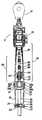
- FIG. 1is a front view of the well casing system of the present invention, including some elements of the well casing system shown in partial cross section;
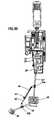
- FIG. 2is a side view of the well casing system of the present invention; depicting the top drive unit and the present invention;
- FIGS. 3 a - 3 care side views of the well casing system in which the links of the systems are extended or retracted in various arrangements.
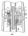
- FIG. 4depicts a cross section of the gripper assembly of the present invention.
- FIGS. 1 through 5A front view of the well casing system for a top drive is shown in FIG. 1, and a side view of the system is shown in FIG. 2 .
- the top drive unitindicated generally as 5 , is coupled to a travelling block 10 .
- a drilling lineis reeved through the sheaves of the travelling block 10 and is coupled to the drawworks of the drilling rig.
- the drawworks operatorcan draw in or release the drilling line to respectively raise or lower the travelling block 10 , which in turn raises or lowers the top drive unit 5 .
- the size of the travelling block 10depends on the depth of the well, which also affects the amount of equipment that the travelling block 10 will need to support.
- Top drive 5has a motor or drive 15 that is coupled to a drive shaft 20 .
- Top drive 5serves as a source of hydraulic power for many of the elements of the invention.
- the drilling crewstabs a tool connector into the top of the drill stem.
- the top driverotates the drill stem and the bit.
- the drilling riguses a top drive, the rig does not use a conventional swivel, Kelly, or Kelly bushing. Drilling rigs using a top drive, however, still need a rotary table and master bushing to provide a location for the slips necessary to suspend the pipes of the drilling operation.
- a lifting elevator 25 and a transfer elevator 30Coupled to the top drive 5 are a lifting elevator 25 and a transfer elevator 30 .
- the transfer elevator 30is a side-door style elevator and can clamp around a single joint of casing 35 . Elevators 25 and 30 may be remotely engaged and released by the operator. Because elevators 30 hoist casing by supporting the casing collar on the square shoulders of the casing collar, elevators 30 are known as shoulder-type elevators. Elevators 25 and 30 are coupled to top drive 5 , which is in turn coupled to the travelling block 10 . When the drawworks of the drilling rig draws in or releases the drill line, the stem or joint casing 35 that is clamped by elevators 25 and 30 is likewise raised or lowered.
- Transfer elevator 30typically has a lifting capacity of 150 tons, and lifting elevator 25 may be used to hoist loads greater than 150 tons.
- the lifting capacity of the slip-type lifting elevator 25is not limited, as is the case with shoulder-style elevators. As such, transfer elevator 30 is intended to hoist single joints of casing 35 , while lifting elevator 25 can be used to hoist the entire casing load.
- Lifting elevators 25are designed to support the entire casing string as well as a pair of secondary links 32 .
- Secondary links 32are used for the transfer of single joint casing.
- Lifting elevator 25has two sets of support ears 26 a and 26 b.
- the lower portion of a set of primary links 27have eyeholes 28 that couple to the upper support ears 26 a of lifting elevator 25 .
- the upper portion of primary links 27is coupled to the top drive 5 .
- the lower portion of each of the secondary links 32have eyeholes 33 that couple to support ears 34 of transfer elevator 30 .
- the upper portion of each of the secondary links 32includes eyeholes 31 that are coupled to support ears 26 b of lifting elevator 25 .
- coupled to secondary links 32is a secondary link tilt 40 (not shown in FIG.
- Secondary link tilts 40are coupled to primary links 27 by hinged connections 43 a and to secondary links 32 by hinged connections 43 b. Secondary link tilts 40 are coupled to links 27 and 32 such that when cylinders 42 of secondary link tilts 40 retract or extend, secondary link 32 and transfer elevator 30 pivots about support ear 26 of lifting elevator 25 as shown in FIGS. 3A-3C.
- primary links 27may be extended by primary link tilts 29 .
- Primary link tilt 29includes a rod 39 and a cylinder 37 .
- FIG. 3Asecondary links 32 are extended, and primary link 27 is not extended.
- primary links 27 and secondary links 32are extended.
- rod 39 of primary link tilt 29is extended, resulting in the extension of primary links 27 in a direction opposite primary link tilt 29 .
- the top drive well casing systemincludes a handling mechanism, which is indicated at 45 .
- Handler 45can be remotely controlled to rotate 360 degrees about its vertical axis or to rotate to a desired rotation position.
- the rotation of handler 45likewise causes elevators 25 and 30 to rotate, allowing these elevators to be rotated around their axis and to be rotated to any rotational location around their axis.
- a casing make-up assembly(CMA) (shown in part in section in FIG. 1 and FIG. 2) is coupled to a drive shaft 20 .
- CMA 55comprises a telescoping module 60 , knuckle joints 65 , rotary manifold 70 and a gripper head or gripping assembly 75 .
- the telescoping module 60provides compensation for any vertical movement and vertical position variances of the casing 35 relative to top drive 5 .
- Knuckle joints 65are similar in function to universal joints and allow for any misalignment of casing 35 relative to the vertical drive shaft 20 of top drive 5 .
- FIG. 4Shown in FIG. 4 is a cross-section of a gripper head, which is indicated generally at 75 .
- a gripper headwhich is indicated generally at 75 .
- the primary function of gripper head 75is in making up the casing.
- Gripper head 75includes a protruding section 80 that is sized to be inserted into casing 35 .
- a radial die assembly 85encircles the top of casing 35 , which may have either an integral female thread or a separate coupling.
- Radial die assembly 85comprises several die blocks 90 that are coupled to hydraulic actuators 95 . When actuators 95 are engaged, die blocks 90 are pushed in and the dies therein contact the casing 35 . The dies within die blocks 90 have teeth or are otherwise shaped to grip the casing 35 . As a result of this connection, gripper head 75 clamps or grips the top of casing 35 .
- the casingincludes the casing coupling 100 .
- rotary manifold 70includes internal pathways or channels 71 a and 71 b for the passage of hydraulic fluid or air through rotary manifold 70 .
- the channels 71 a and 71 bhave seals 113 for fluid isolation between passages.
- rotary manifold 70provides a stationary pathway for the passage of hydraulic or pneumatic power to the components of gripper head 75 .
- Bearings 77permit the rotational movement of the gripper assembly within manifold 70 .
- Bearings 77may include roller bearings or other suitable bearings that allow one body to rotate about another body.
- one or more restraints 72are coupled to the rotary manifold 70 to prevent it from turning. Coupled between rotary manifold 70 and link 27 is an anti-rotation member 73 .
- Anti-rotation member 73may comprise, for example, a hydraulic cylinder 79 that is able to retract a hydraulic rod 81 .
- Manifold 70may also be prevented from rotating by cable restraint 72 , which is coupled to a hook attachment at manifold 70 . Any other suitable restraint may be used to prevent manifold 70 from rotating, including other forms of bars or cables.
- a sealIn addition to gripping the casing 35 , another function of the gripper head 75 is to transmit the circulation of drilling fluid or mud through the casing 35 . In order to pump mud, a seal must be established between the casing 35 and the gripper head 75 . As previously mentioned, it is not desirable to establish the seal with a mechanism that screws into the casing coupling. The integrity of the well is dependent on the casing threading. Thus, it is desirable to make up the casing only once. If a seal were established by a mechanism that screws into the threading, then the casing would have to be made up twice and broken once. Therefore, although it is easy to employ a seal that screws into the casing threading, it is not desirable.
- Sealing element 110performs the function of creating a seal between the casing 35 and the gripper head 75 .
- Sealing element 110is encircled by the gripper head 75 and is preferably located between the nose section 80 and the radial die assembly 85 .
- Sealing element 110preferably comprises an elastomer element or layer over a steel body.
- Sealing element 110is self energized to establish an initial seal and further energized by the pressure inside the casing 35 , which forces the sealing element 110 against the walls of the casing 35 , thereby forming a seal to allow mud or drilling fluid to be pumped though the casing assembly. It is also possible to force seal the sealing element by activating it with hydraulic pressure.
- An air vent 120is provided to vent or release air and pressure from the interior of the casing 35 and nose section 80 .
- the well casing system of the present inventionincludes a control system that is able to manipulate the elevators, link tilts, and other elements of the well casing system.
- the control system of the well casing systemis able to open and close transfer elevator 30 and lifting elevator 25 , and retract and extend secondary link tilt 40 .
- the control system of the well casing systemis also able to clamp and unclamp die blocks 90 and to engage and disengage sealing element 110 .
- the control system of the well casing systemis also able to open and close vent 120 .
- the control system of the well casing systemis also able to monitor feedback loops that include sensors or monitors on the elements of the well casing system.
- sensors of the control system of the well casing systemmonitor the open and close status of lifting elevator 40 , the open or close status of air vent 120 , and the clamp status of die block 90 .
- the control system of the well casing systemis powered by a self-contained power source, such as a battery or generator, and is designed or rated for use in a hazardous working environment. Communication with the processor of the control system can be accomplished through a wireless communications link.
- the well casing system described hereininvolves the following steps when transferring a uncoupled joint of casing 35 from the rig floor to the casing string. Secondary link tilt 40 is extended until transfer elevator 30 is positioned over and clamped around the uncoupled joint of casing. After the transfer elevator is closed, the uncoupled joint of casing is hoisted with the top drive 5 so that the joint of casing is in a vertical position. The uncoupled joint of casing is lowered onto the existing secured casing string such that the male thread of the casing joint stabs into the casing coupling or integral female thread of existing casing string 35 .
- transfer elevator 30is used to transfer a single joint of uncoupled casing from the horizontal position to vertical orientation and stab the single joint of casing into the casing string. With the handler 45 and primary link tilt 29 , the uncoupled joint of casing is maneuvered until the threads of the casing joints are aligned and can be made up. At this time, lifting elevator 25 and transfer elevator 30 are not exerting a lifting force on the uncoupled casing joint. Lifting elevator 25 is used to guide the top of the casing joint.
- the handler 45can rotate 360 degrees about its vertical axis and because of the angle of the primary links that can be accomplished by the extension or retraction of the primary link tilt 29 , the uncoupled casing joint 35 can be placed in an almost infinite number of spatial positions to facilitate the precise alignment of the threads of the uncoupled casing joint and the secured casing string. Because of the precise alignment provided by the well casing system of the present invention, there is no need for a crewmember to stand on the stabbing board to manually align the joint of the uncoupled joint of casing to the secured casing string.
- the threads of the jointsare made up to the desired torque with CMA 55 .
- the top driveis lowered until the gripper head 75 engages at the top of the uncoupled casing joint.
- the die blocks 90are closed such that dies of the die block clamp the coupling. If no coupling is present, as in the case of an integrated female thread casing, the dies of the die blocks clamp to the casing.
- the gripper head 75With the gripper head 75 now solidly connected to the single joint, the thread can now be screwed in and torqued up.
- the rotation for the make-up and torqueis provided and controlled by top drive 5 . This operation can also be controlled and monitored with torque-turn instrumentation that is used to verify proper thread advancement.
- telescoping module 60compensates for any advance in drive shaft 20 and the casing string, permitting the uncoupled single joint to be screwed into the coupling or integrated female thread of the casing string.
- Knuckle joint 65allows the uncoupled casing joint and gripper head 75 to be at an angle to main shaft 20 .
- the ability to align an uncoupled casing joint for stabbing and proper threadingis affected by how the casing string is hanging in the slips and hole.
- the accommodation of an offset between the casing string to the main shaftis necessary to accomplish perfect thread alignment between the single joint and the casing string.
- the knuckle jointhas to be designed such that rotation with this offset is possible. It also must allow pumping liquid through the joint at high pressure (up to 7500 PSI).
- the casingcan be sealed by sealing element 110 , permitting liquids, typically drilling mud, to be pumped into the casing string.
- the entire casing stringis lifted by top drive 5 and lifting elevator 30 and the drill floor slips are released. The entire casing string can then be lowered farther into the hole.
- the floor slipsare reapplied to secure the casing string.
- Lifting elevator 30is released, and the operation of adding another uncoupled single joint to the casing string can be repeated.
- telescoping module 60permits the movement of the lifting elevator slip components.
- top drive 5is able to manipulate the position and rotation of the uncoupled casing joint and the casing string.
Landscapes
- Engineering & Computer Science (AREA)
- Life Sciences & Earth Sciences (AREA)
- Geology (AREA)
- Mining & Mineral Resources (AREA)
- Mechanical Engineering (AREA)
- Physics & Mathematics (AREA)
- Environmental & Geological Engineering (AREA)
- Fluid Mechanics (AREA)
- General Life Sciences & Earth Sciences (AREA)
- Geochemistry & Mineralogy (AREA)
- Earth Drilling (AREA)
Abstract
Description
The present invention relates to the field of oil or gas well drilling and more particularly to a method and apparatus for handling or running casing.
A joint of casing typically includes threaded couplings at either end. These threaded couplings allow two joints of casing to be screwed or threaded together. Generally, a joint of casing has a male thread on one end of the casing with a corresponding female thread on the other end. There are various types of threads depending on the requirements of strength and the type of casing.
Initially, the process of handling or running casing is not very different from running drill pipe. Once the joints of casing are brought to the site, they are inspected and measured. The casing joint is then taken up the ramp to the drill floor, latched to an elevator, suspended from the travelling block by two equal length slings or steel cables, and then hoisted by the travelling block until the casing is hanging vertically. After lowering the joint through the rotary table, the drill crew then places the slips around the first joint of casing to secure it to the master bushing of the rotary table. The slips now suspend the casing string in the hole. Because the hole in the rotary floor is slightly tapered, the slips act as a wedge, holding the casing vertically in place by friction. Slips support the casing within a conical bushing. Subsequent joints of casing are then stabbed and screwed into the secured casing below to form the casing string.
The process of stabbing is somewhat of an art because aligning the casing properly is both very difficult and important. Although the diameters of the casing are relatively large, the threading on each can be quite fine. As a result, the casings are very sensitive to alignment and threading. The act of stabbing is generally performed by a derrickman located on a stabbing board. The stabbing board is a platform that is normally located about 40 feet above the drill floor, but generally it can be moved up or down depending on the length of the casing and other circumstances. The derrickman on the stabbing board holds the hanging casing joint and positions it over the secured casing below. Generally, crew-members on the drilling deck, such as the tong operators, direct the derrickman on the stabbing board to align the casing. The tong operator(s) then aligns the threads of the casing and couples them together using a pair of casing tongs. These casing tongs are hydraulically powered and clamp onto the casing with jaws. The tong operator can use the casing tongs to rotate the hanging casing and thread it into the coupling of the secured casing below. Proper make-up of the torque is critical for a good connection. During the process of threading one piece of casing to another piece of casing, lifting elevators are attached to the casing load, which consists of the casing string or casing assembly. The slips are released and the casing load is lowered further down into the hole by the elevators. The slips are once again attached to secure the casing load, and the process of adding casing is repeated. Generally, a single-joint (transfer) elevator is used to hoist and position the next piece of casing to be stabbed into the secured casing assembly (or casing load) below while the slip-type (lifting) elevator is used to hoist the entire casing load.
The conventional method of stabbing casing has many inherent risks. There are several hazards associated with having to have a derrickman perform the stabbing operation on the stabbing board. The stabbing board is suspended approximately forty (40) feet in the air and as a result, the derrickman is exposed to the risk of falling or being knocked off the platform by various equipment. In addition, there is a risk of falling while climbing to or from the stabbing board. Although the stabbing board serves only one purpose, it remains an obstacle to other equipment in other operations. Even though the stabbing board can be folded up, it can still snag or catch nearby equipment. Further, because the stabbing board is fairly complicated and because it must be positioned to avoid completely blocking other equipment and operations, the land rig crew spends a considerable amount of time setting up and breaking down the stabbing board.
Other problems with the conventional method of stabbing casing stem from the use of the transfer elevator. Use of the transfer elevator to hoist and position the joint of casing to be stabbed is a slow and cumbersome process and involves several manual steps. The drilling rig environment is a hazardous one, and the more manual steps involved in a given process, the greater the likelihood of damaged equipment and injury to the crew. In addition, the transfer elevator presents several possible hazards. The transfer elevator supports the casing joint with relatively light slings. These slings do not allow the operator to control how the casing joint will hang. As a result, there is a real possibility that the casing joint will snag on a piece of equipment as it is hoisted up by the transfer elevator. Because the transfer elevator is powered by the rig's drawworks, there is more power associated with the transfer elevator than there is capacity to hoist. Therefore, if the casing joint does get snagged on a piece of equipment, the slings are prone to being pulled apart by the excessive power and the casing joint will drop.
Increasingly, drilling contractors are using top drive systems. A top drive is a drilling tool that hangs from the traveling block, and has one or more motors to power a drive shaft to which crewmembers attach the drill string. Because the unit's motor can rotate the drill string, no Kelly or Kelly bushing is required. The top drive unit also incorporates a spinning capability and a torque wrench. In addition the top drive system has elevators on links. The conventional method of handling casing requires the use of casing tongs, a costly contract service. The tong equipment generally also requires an outside crew to operate them. Given the power and control of the top drive, it is desirable to use the top drive system to replace the expensive services of the tong operators. In addition, it would be desirable to eliminate the need for a crewmember on a stabbing board and use of slings on the transfer elevator in the casing stabbing process.
In accordance with the present invention, a well casing system and a method for using a well casing system is provided that substantially eliminates or reduces the safety risk, expense, and problems associated with handling or running casing in conventional drilling rigs. The well casing system includes a link tilt, lifting elevator, transfer elevator, and casing make-up assembly. The well casing system of the present invention may be used to couple a joint of casing to a casing string that is in place in the well hole. The elevators of the well casing system clamp to a joint of casing, hoist the joint of casing, align the joint of casing with the casing string that is secured in the well hole. After the joint of casing is aligned with the casing string, the joint of casing is stabbed into the casing string, and the threads of the joint of casing and the casing string are torqued together.
One technical advantage of the present invention is that it eliminates the hazards and inefficient use of a conventional transfer elevators. Such hazards include the possibility of snagging the casing joint on a piece of equipment and dropping it onto the deck below. Another technical advantage of the present invention is that it eliminates the need for a crewmember to man a stabbing board. This eliminates the need for a crewmember to occupy a relatively dangerous location on the drilling rig. It also eliminates the need for the stabbing board, which presents itself as an obstruction to other drilling operations and equipment. Another technical advantage of the present invention is that it eliminates the need for a power tong operator and specialized casing crew. In place of a power tong, operator the joints of casing can be made-up by the connection of a top drive, through a drive shaft, to a gripper assembly that is coupled to the joint of casing that is to be made up. Another advantage of the invention is a system for repeatedly coupling joints of casing to an in-place casing string in which the positional alignment of each successive joint of casing is substantially identical to the alignment of the previous joint of casing. Because the position of the link tilts and elevators are known, the same positioning can be used for each successive joint of casing.
Other technical advantages of the present invention will be readily apparent to one skilled in the art from the following figures, descriptions and claims.
A more complete understanding of the present embodiments and advantages thereof may be acquired by referring to the following description taken in conjunction with the accompanying drawings, in which like reference numbers indicate like features, and wherein:
FIG. 1 is a front view of the well casing system of the present invention, including some elements of the well casing system shown in partial cross section;
FIG. 2 is a side view of the well casing system of the present invention; depicting the top drive unit and the present invention;
FIGS. 3a-3care side views of the well casing system in which the links of the systems are extended or retracted in various arrangements; and
FIG. 4 depicts a cross section of the gripper assembly of the present invention.
Preferred embodiments and their advantages are best understood by reference to FIGS. 1 through 5, wherein like numbers are used to indicate like and corresponding parts. A front view of the well casing system for a top drive is shown in FIG. 1, and a side view of the system is shown in FIG.2. The top drive unit, indicated generally as5, is coupled to a travellingblock 10. A drilling line is reeved through the sheaves of the travellingblock 10 and is coupled to the drawworks of the drilling rig. The drawworks operator can draw in or release the drilling line to respectively raise or lower the travellingblock 10, which in turn raises or lowers thetop drive unit 5. The size of the travellingblock 10 depends on the depth of the well, which also affects the amount of equipment that the travellingblock 10 will need to support.Top drive 5 has a motor or drive15 that is coupled to adrive shaft 20.Top drive 5 serves as a source of hydraulic power for many of the elements of the invention. During the drilling process, the drilling crew stabs a tool connector into the top of the drill stem. When the driller starts the top drive's motor, the top drive rotates the drill stem and the bit. Because the drilling rig uses a top drive, the rig does not use a conventional swivel, Kelly, or Kelly bushing. Drilling rigs using a top drive, however, still need a rotary table and master bushing to provide a location for the slips necessary to suspend the pipes of the drilling operation.
Coupled to thetop drive 5 are a liftingelevator 25 and atransfer elevator 30. Thetransfer elevator 30 is a side-door style elevator and can clamp around a single joint ofcasing 35.Elevators elevators 30 hoist casing by supporting the casing collar on the square shoulders of the casing collar,elevators 30 are known as shoulder-type elevators.Elevators top drive 5, which is in turn coupled to the travellingblock 10. When the drawworks of the drilling rig draws in or releases the drill line, the stem orjoint casing 35 that is clamped byelevators Transfer elevator 30 typically has a lifting capacity of 150 tons, and liftingelevator 25 may be used to hoist loads greater than 150 tons. The lifting capacity of the slip-type lifting elevator 25 is not limited, as is the case with shoulder-style elevators. As such,transfer elevator 30 is intended to hoist single joints ofcasing 35, while liftingelevator 25 can be used to hoist the entire casing load.
Liftingelevators 25 are designed to support the entire casing string as well as a pair ofsecondary links 32.Secondary links 32 are used for the transfer of single joint casing. Liftingelevator 25 has two sets ofsupport ears 26aand26b.The lower portion of a set ofprimary links 27 haveeyeholes 28 that couple to the upper support ears26aof liftingelevator 25. The upper portion ofprimary links 27 is coupled to thetop drive 5. The lower portion of each of thesecondary links 32 haveeyeholes 33 that couple to supportears 34 oftransfer elevator 30. The upper portion of each of thesecondary links 32 includeseyeholes 31 that are coupled to supportears 26bof liftingelevator 25. Referring to FIG. 2, coupled tosecondary links 32 is a secondary link tilt40 (not shown in FIG.1), which is controlled by ahydraulic mechanism 41 to retract or extend the secondary link tilts. Secondary link tilts40 are coupled toprimary links 27 by hinged connections43aand tosecondary links 32 by hingedconnections 43b.Secondary link tilts40 are coupled tolinks cylinders 42 of secondary link tilts40 retract or extend,secondary link 32 andtransfer elevator 30 pivots about support ear26 of liftingelevator 25 as shown in FIGS. 3A-3C. As shown in FIGS. 3a-3c,primary links 27 may be extended by primary link tilts29.Primary link tilt 29 includes arod 39 and acylinder 37. In FIG. 3A,secondary links 32 are extended, andprimary link 27 is not extended. In FIG. 3B,primary links 27 andsecondary links 32 are extended. In FIG. 3C,rod 39 ofprimary link tilt 29 is extended, resulting in the extension ofprimary links 27 in a direction oppositeprimary link tilt 29.
The top drive well casing system includes a handling mechanism, which is indicated at45.Handler 45 can be remotely controlled to rotate 360 degrees about its vertical axis or to rotate to a desired rotation position. The rotation ofhandler 45 likewise causeselevators drive shaft 20.CMA 55 comprises atelescoping module 60,knuckle joints 65,rotary manifold 70 and a gripper head or grippingassembly 75. Thetelescoping module 60 provides compensation for any vertical movement and vertical position variances of thecasing 35 relative totop drive 5.Knuckle joints 65 are similar in function to universal joints and allow for any misalignment ofcasing 35 relative to thevertical drive shaft 20 oftop drive 5.
Shown in FIG. 4 is a cross-section of a gripper head, which is indicated generally at75. There is often at least some metal deformation by design in the make up of the casing threading. As such, it is desirable to make-up the casing only once. The primary function ofgripper head 75 is in making up the casing.
Because of the rotation ofCMA 55, hydraulic hoses are not connected directly togripper head 75. Instead, a hydraulic supply is provided torotary manifold 70. As shown in FIG. 4,rotary manifold 70 includes internal pathways orchannels 71aand71bfor the passage of hydraulic fluid or air throughrotary manifold 70. Thechannels 71aand71bhaveseals 113 for fluid isolation between passages. As such,rotary manifold 70 provides a stationary pathway for the passage of hydraulic or pneumatic power to the components ofgripper head 75.Bearings 77 permit the rotational movement of the gripper assembly withinmanifold 70.Bearings 77 may include roller bearings or other suitable bearings that allow one body to rotate about another body. To restrainrotary manifold 70 from rotating, one ormore restraints 72 are coupled to therotary manifold 70 to prevent it from turning. Coupled betweenrotary manifold 70 andlink 27 is ananti-rotation member 73.Anti-rotation member 73 may comprise, for example, ahydraulic cylinder 79 that is able to retract ahydraulic rod 81.Manifold 70 may also be prevented from rotating bycable restraint 72, which is coupled to a hook attachment atmanifold 70. Any other suitable restraint may be used to prevent manifold70 from rotating, including other forms of bars or cables.
In addition to gripping thecasing 35, another function of thegripper head 75 is to transmit the circulation of drilling fluid or mud through thecasing 35. In order to pump mud, a seal must be established between thecasing 35 and thegripper head 75. As previously mentioned, it is not desirable to establish the seal with a mechanism that screws into the casing coupling. The integrity of the well is dependent on the casing threading. Thus, it is desirable to make up the casing only once. If a seal were established by a mechanism that screws into the threading, then the casing would have to be made up twice and broken once. Therefore, although it is easy to employ a seal that screws into the casing threading, it is not desirable.
The well casing system of the present invention includes a control system that is able to manipulate the elevators, link tilts, and other elements of the well casing system. The control system of the well casing system is able to open andclose transfer elevator 30 and liftingelevator 25, and retract and extendsecondary link tilt 40. The control system of the well casing system is also able to clamp and unclamp die blocks90 and to engage and disengage sealingelement 110. The control system of the well casing system is also able to open andclose vent 120. The control system of the well casing system is also able to monitor feedback loops that include sensors or monitors on the elements of the well casing system. For example, sensors of the control system of the well casing system monitor the open and close status of liftingelevator 40, the open or close status ofair vent 120, and the clamp status ofdie block 90. The control system of the well casing system is powered by a self-contained power source, such as a battery or generator, and is designed or rated for use in a hazardous working environment. Communication with the processor of the control system can be accomplished through a wireless communications link.
In operation, the well casing system described herein involves the following steps when transferring a uncoupled joint of casing35 from the rig floor to the casing string.Secondary link tilt 40 is extended untiltransfer elevator 30 is positioned over and clamped around the uncoupled joint of casing. After the transfer elevator is closed, the uncoupled joint of casing is hoisted with thetop drive 5 so that the joint of casing is in a vertical position. The uncoupled joint of casing is lowered onto the existing secured casing string such that the male thread of the casing joint stabs into the casing coupling or integral female thread of existingcasing string 35. In sum,transfer elevator 30 is used to transfer a single joint of uncoupled casing from the horizontal position to vertical orientation and stab the single joint of casing into the casing string. With thehandler 45 andprimary link tilt 29, the uncoupled joint of casing is maneuvered until the threads of the casing joints are aligned and can be made up. At this time, liftingelevator 25 andtransfer elevator 30 are not exerting a lifting force on the uncoupled casing joint. Liftingelevator 25 is used to guide the top of the casing joint. Because thehandler 45 can rotate 360 degrees about its vertical axis and because of the angle of the primary links that can be accomplished by the extension or retraction of theprimary link tilt 29, the uncoupled casing joint35 can be placed in an almost infinite number of spatial positions to facilitate the precise alignment of the threads of the uncoupled casing joint and the secured casing string. Because of the precise alignment provided by the well casing system of the present invention, there is no need for a crewmember to stand on the stabbing board to manually align the joint of the uncoupled joint of casing to the secured casing string.
Following the alignment of the uncoupled casing joint and the secured casing string, the threads of the joints are made up to the desired torque withCMA 55. The top drive is lowered until thegripper head 75 engages at the top of the uncoupled casing joint. At this time, the die blocks90 are closed such that dies of the die block clamp the coupling. If no coupling is present, as in the case of an integrated female thread casing, the dies of the die blocks clamp to the casing. With thegripper head 75 now solidly connected to the single joint, the thread can now be screwed in and torqued up. The rotation for the make-up and torque is provided and controlled bytop drive 5. This operation can also be controlled and monitored with torque-turn instrumentation that is used to verify proper thread advancement. During the make-up of the casing string,telescoping module 60 compensates for any advance indrive shaft 20 and the casing string, permitting the uncoupled single joint to be screwed into the coupling or integrated female thread of the casing string.Knuckle joint 65 allows the uncoupled casing joint andgripper head 75 to be at an angle tomain shaft 20. The ability to align an uncoupled casing joint for stabbing and proper threading is affected by how the casing string is hanging in the slips and hole. The accommodation of an offset between the casing string to the main shaft is necessary to accomplish perfect thread alignment between the single joint and the casing string. The knuckle joint has to be designed such that rotation with this offset is possible. It also must allow pumping liquid through the joint at high pressure (up to 7500 PSI).
Following the make-up of the casing joints, the casing can be sealed by sealingelement 110, permitting liquids, typically drilling mud, to be pumped into the casing string. Following this process, the entire casing string is lifted bytop drive 5 and liftingelevator 30 and the drill floor slips are released. The entire casing string can then be lowered farther into the hole. Once the casing string is lowered into the hole by the length of a joint, the floor slips are reapplied to secure the casing string. Liftingelevator 30 is released, and the operation of adding another uncoupled single joint to the casing string can be repeated. During the hoisting and lowering of the casing string, ifgripper head 75 is sealed oncasing 35,telescoping module 60 permits the movement of the lifting elevator slip components. Throughout the process of coupling an uncoupled casing joint to the casing string,top drive 5 is able to manipulate the position and rotation of the uncoupled casing joint and the casing string.
Although the disclosed embodiments have been described in detail, it should be understood that various changes, substitutions and alterations can be made to the embodiments without departing from their spirit and scope.
Claims (20)
1. An apparatus for coupling a joint of casing to a casing string secured in a subterranean well, comprising:
a top drive;
a first set of links, a first end of each link in the first set of links being coupled to the top drive;
a first casing elevator coupled to a second end of each link in the first set of links;
a first link tilt for pivoting each link in the first set of links about its first end; and
a gripper assembly coupled to the top drive and operable to secure and engage the joint of casing;
wherein the top drive is operable to rotate the gripper assembly, thereby rotating the joint of casing and coupling the joint of casing to the casing string.
2. The apparatus ofclaim 1 , wherein the gripper assembly comprises a nose sized to fit inside the joint of casing and shaped to guide the gripper assembly into the joint of casing.
3. The apparatus ofclaim 1 , wherein the gripper assembly further comprises,
a plurality of dies with surface suitable for gripping the outside surface of the joint of casing, wherein the dies are arranged in a radial configuration; and
a plurality of hydraulic actuators coupled to the dies wherein the hydraulic actuators may push the dies against the outer surface of the joint of casing such that the gripper assembly grips the joint of casing.
4. The apparatus ofclaim 1 , wherein the gripper assembly is coupled to a rotary manifold that includes a plurality of channels capable of delivering fluid to the gripper assembly while the gripper assembly is rotating.
5. The apparatus ofclaim 1 , further comprising a drive shaft coupled between the top drive and the gripper assembly, the drive shaft transmitting rotational force from the top drive to the gripper assembly.
6. The apparatus ofclaim 1 wherein the operation of the gripper assembly and the first link tilt can be remotely controlled.
7. The apparatus ofclaim 1 , wherein the gripper assembly comprises a sealing member to form a seal to allow fluids to be pumped into the casing.
8. The apparatus ofclaim 7 , wherein the sealing member is a self-energizing seal.
9. The apparatus ofclaim 7 , wherein the sealing member is remotely actuated to establish or release the seal.
10. The apparatus ofclaim 1 , further comprising:
a second set of links, a first end of each link in the second set of links being coupled to the top drive;
a second casing elevator coupled to a second end of each link in the second set of links; and
a second link tilt for pivoting each link in the second set of links about its first end.
11. An apparatus for coupling a joint of casing to a casing string secured in a subterranean well, comprising:
a top drive:
a first set of links, a first end of each link in the first set of links being coupled to the top drive;
a first casing elevator coupled to a second end of each link in the first set of links;
a first link tilt for pivoting each link in the first set of links about its first end;
a gripper assembly coupled to the top drive and operable to secure and engage the joint of casing; and
a drive shaft coupled between the ton drive and the gripper assembly, the drive shaft transmitting rotational force from the top drive to the gripper assembly;
wherein the top drive is operable to rotate the gripper assembly, thereby rotating the joint of casing and coupling the joint of casing to the casing string; and
wherein the drive shaft comprises,
a telescoping module capable of compensating for movement of the drive shaft along the drive shaft's vertical axis during the coupling of the casing to the casing string by the rotation of the gripper assembly; and
at least one a knuckle joint that compensates for misalignment of the gripper assembly head and the drive shaft during rotation of the drive shaft.
12. The apparatus ofclaim 11 , wherein the telescoping module is remotely actuated.
13. The apparatus ofclaim 11 , wherein the at least one knuckle joint is remotely actuated.
14. An apparatus for coupling a joint of casing to a casing string secured in a subterranean well, comprising:
a top drive:
a first set of links, a first end of each link in the first set of links being coupled to the top drive;
a first casing elevator coupled to a second end of each link in the first set of links;
a first link tilt for pivoting each link in the first set of links about its first end;
a gripper assembly coupled to the top drive and operable to secure and engage the joint of casing; and
a drive shaft coupled between the top drive and the gripper assembly, the drive shaft transmitting rotational force from the top drive to the gripper assembly;
wherein the gripper assembly comprises a sealing member to form a seal to allow fluids to be pumped into the casing and a remotely actuated air vent valve to release air from the casing; and
wherein the ton drive is operable to rotate the gripper assembly, thereby rotating the joint of casing and coupling the joint of casing to the casing string.
15. A method for hoisting a joint of casing, positioning the joint of casing above a casing string, and stabbing the joint of casing into the casing string such that the joint of casing is coupled with the casing string, comprising the steps of:
providing a top drive system, the top drive system comprising,
a lifting elevator able to be clamped around the casing string for the purpose of hoisting the casing string;
a transfer elevator able to be clamped around the joint of casing for the purpose of hoisting a joint of casing;
a drive shaft;
a drive to rotate the drive shaft;
a handler able to rotate the lifting elevator and the transfer elevator in a horizontal plane;
a link tilt comprising one or more hydraulic actuators, wherein the link tilt is coupled to the transfer elevator such that the extension or retraction of the hydraulic actuators can pivot the transfer elevator about a point located on a vertical axis;
providing a casing make-up assembly coupled to the drive shaft, the casing make-up assembly comprising,
a gripper assembly, the gripper assembly comprising,
a nose sized to be inserted in the joint of casing;
a gripping member to clamp around the joint of casing;
clamping the transfer elevator around a joint of casing;
hoisting the joint of casing above the casing string;
positioning the joint of casing directly above the casing string by pivoting and rotating the transfer elevator;
lowering the joint of casing until it rests on the casing string;
lowering the gripper head until the nose is inserted in the joint of casing;
unclamping the transfer elevator;
positioning the lifting elevator using the link tilt until thread alignment is achieved;
clamping the gripping member around the joint of casing; and
rotating the drive shaft, thereby rotating the gripper assembly and joint of casing such that the joint of casing is coupled to the casing string.
16. The method ofclaim 15 , wherein the step of positioning the joint of casing directly above the casing string by pivoting and rotating the transfer elevator is performed by remote control.
17. The method ofclaim 15 , wherein the position of the link tilt and lifting elevator at the time of the alignment of the joint of casing and the casing string is saved to memory such that the position of the link tilt and the lifting elevator is the same for successive joints of casing to be coupled to the casing string.
18. A method of adding a joint of casing to a casing string in a well bore comprising the following steps:
using a first link tilt to position a first casing elevator such that the first casing elevator can be coupled to the joint of casing;
using a gripper assembly attached to a top drive to grasp and rotate the joint of casing thereby coupling the joint of casing to the casing string; and
using a second casing elevator to lower the casing string into the well bore.
19. The method ofclaim 18 , further comprising the step of using the first link tilt to position the joint of casing over the casing string.
20. The method ofclaim 18 , further comprising the step of using a second link tilt to maneuver the second casing elevator, thereby aligning the joint of casing with the casing string prior to coupling the single joint of casing to the casing string.
Priority Applications (6)
| Application Number | Priority Date | Filing Date | Title |
|---|---|---|---|
| US10/076,021US6679333B2 (en) | 2001-10-26 | 2001-10-26 | Top drive well casing system and method |
| AU2002335886AAU2002335886A1 (en) | 2001-10-26 | 2002-10-23 | Top drive well casing system and method |
| PCT/US2002/033939WO2003038229A2 (en) | 2001-10-26 | 2002-10-23 | Top drive well casing system and method |
| CA2678206ACA2678206C (en) | 2001-10-26 | 2002-10-23 | Top drive well casing system and method |
| CA2503692ACA2503692C (en) | 2001-10-26 | 2002-10-23 | Top drive well casing system and method |
| US10/758,975US6920926B2 (en) | 2001-10-26 | 2004-01-16 | Top drive well casing system |
Applications Claiming Priority (1)
| Application Number | Priority Date | Filing Date | Title |
|---|---|---|---|
| US10/076,021US6679333B2 (en) | 2001-10-26 | 2001-10-26 | Top drive well casing system and method |
Related Child Applications (1)
| Application Number | Title | Priority Date | Filing Date |
|---|---|---|---|
| US10/758,975DivisionUS6920926B2 (en) | 2001-10-26 | 2004-01-16 | Top drive well casing system |
Publications (2)
| Publication Number | Publication Date |
|---|---|
| US20030079884A1 US20030079884A1 (en) | 2003-05-01 |
| US6679333B2true US6679333B2 (en) | 2004-01-20 |
Family
ID=22129438
Family Applications (2)
| Application Number | Title | Priority Date | Filing Date |
|---|---|---|---|
| US10/076,021Expired - Fee RelatedUS6679333B2 (en) | 2001-10-26 | 2001-10-26 | Top drive well casing system and method |
| US10/758,975Expired - Fee RelatedUS6920926B2 (en) | 2001-10-26 | 2004-01-16 | Top drive well casing system |
Family Applications After (1)
| Application Number | Title | Priority Date | Filing Date |
|---|---|---|---|
| US10/758,975Expired - Fee RelatedUS6920926B2 (en) | 2001-10-26 | 2004-01-16 | Top drive well casing system |
Country Status (4)
| Country | Link |
|---|---|
| US (2) | US6679333B2 (en) |
| AU (1) | AU2002335886A1 (en) |
| CA (2) | CA2678206C (en) |
| WO (1) | WO2003038229A2 (en) |
Cited By (121)
| Publication number | Priority date | Publication date | Assignee | Title |
|---|---|---|---|---|
| US20020189863A1 (en)* | 1999-12-22 | 2002-12-19 | Mike Wardley | Drilling bit for drilling while running casing |
| US20030164251A1 (en)* | 2000-04-28 | 2003-09-04 | Tulloch Rory Mccrae | Expandable apparatus for drift and reaming borehole |
| US20030173073A1 (en)* | 2000-04-17 | 2003-09-18 | Weatherford/Lamb, Inc. | Top drive casing system |
| US20040003490A1 (en)* | 1997-09-02 | 2004-01-08 | David Shahin | Positioning and spinning device |
| US20040069500A1 (en)* | 2001-05-17 | 2004-04-15 | Haugen David M. | Apparatus and methods for tubular makeup interlock |
| US20040118613A1 (en)* | 1994-10-14 | 2004-06-24 | Weatherford/Lamb, Inc. | Methods and apparatus for cementing drill strings in place for one pass drilling and completion of oil and gas wells |
| US20040124015A1 (en)* | 1994-10-14 | 2004-07-01 | Vail William Banning | Method and apparatus for cementing drill strings in place for one pass drilling and completion of oil and gas wells |
| US20040140128A1 (en)* | 1994-10-14 | 2004-07-22 | Weatherford/Lamb, Inc. | Methods and apparatus for cementing drill strings in place for one pass drilling and completion of oil and gas wells |
| US20040216892A1 (en)* | 2003-03-05 | 2004-11-04 | Giroux Richard L | Drilling with casing latch |
| US20040216924A1 (en)* | 2003-03-05 | 2004-11-04 | Bernd-Georg Pietras | Casing running and drilling system |
| US20040216925A1 (en)* | 1998-12-22 | 2004-11-04 | Weatherford/Lamb, Inc. | Method and apparatus for drilling and lining a wellbore |
| US20040221997A1 (en)* | 1999-02-25 | 2004-11-11 | Weatherford/Lamb, Inc. | Methods and apparatus for wellbore construction and completion |
| US20040244992A1 (en)* | 2003-03-05 | 2004-12-09 | Carter Thurman B. | Full bore lined wellbores |
| US20040256110A1 (en)* | 2001-10-26 | 2004-12-23 | Canrig Drilling Technology Ltd. | Top drive well casing system and method |
| US20040262013A1 (en)* | 2002-10-11 | 2004-12-30 | Weatherford/Lamb, Inc. | Wired casing |
| US20050000696A1 (en)* | 2003-04-04 | 2005-01-06 | Mcdaniel Gary | Method and apparatus for handling wellbore tubulars |
| US20050000684A1 (en)* | 2000-03-22 | 2005-01-06 | Slack Maurice William | Apparatus for handling tubular goods |
| US20050121232A1 (en)* | 1998-12-22 | 2005-06-09 | Weatherford/Lamb, Inc. | Downhole filter |
| US6913096B1 (en)* | 2002-07-03 | 2005-07-05 | Shawn James Nielsen | Top drive well drilling apparatus |
| US20050173154A1 (en)* | 2004-01-28 | 2005-08-11 | Gerald Lesko | Method and system for connecting pipe to a top drive motor |
| US20050194188A1 (en)* | 2003-10-03 | 2005-09-08 | Glaser Mark C. | Method of drilling and completing multiple wellbores inside a single caisson |
| US20050205250A1 (en)* | 2002-10-11 | 2005-09-22 | Weatherford/Lamb, Inc. | Apparatus and methods for drilling with casing |
| US20050257933A1 (en)* | 2004-05-20 | 2005-11-24 | Bernd-Georg Pietras | Casing running head |
| US20050269104A1 (en)* | 2004-06-07 | 2005-12-08 | Folk Robert A | Top drive systems |
| US20050269105A1 (en)* | 1998-07-22 | 2005-12-08 | Weatherford/Lamb, Inc. | Apparatus for facilitating the connection of tubulars using a top drive |
| US6976298B1 (en)* | 1998-08-24 | 2005-12-20 | Weatherford/Lamb, Inc. | Methods and apparatus for connecting tubulars using a top drive |
| US20060000600A1 (en)* | 1998-08-24 | 2006-01-05 | Bernd-Georg Pietras | Casing feeder |
| US20060032638A1 (en)* | 2004-07-30 | 2006-02-16 | Giroux Richard L | Apparatus and methods of setting and retrieving casing with drilling latch and bottom hole assembly |
| US20060096751A1 (en)* | 2004-11-09 | 2006-05-11 | Matthew Brown | Top drive assembly |
| US20060113084A1 (en)* | 2004-11-30 | 2006-06-01 | Springett Frank B | Pipe gripper and top drive systems |
| USD523210S1 (en) | 2004-06-07 | 2006-06-13 | Varco I/P, Inc. | Block becket for use in a wellbore derrick |
| US20060124357A1 (en)* | 2002-07-29 | 2006-06-15 | Weatherford/Lamb, Inc. | Adjustable rotating guides for spider or elevator |
| USD523451S1 (en) | 2004-06-07 | 2006-06-20 | Varco I/P, Inc. | Support link for wellbore apparatus |
| US20060137911A1 (en)* | 1994-10-14 | 2006-06-29 | Weatherford/Lamb, Inc. | Method and apparatus for cementing drill strings in place for one pass drilling and completion of oil and gas wells |
| USD524334S1 (en) | 2004-06-07 | 2006-07-04 | Varco I/P, Inc. | Swivel body for a well top drive system |
| USD524833S1 (en) | 2004-06-07 | 2006-07-11 | Varco I/P, Inc. | Access platform for a well top drive system |
| US20060151181A1 (en)* | 2005-01-12 | 2006-07-13 | David Shahin | One-position fill-up and circulating tool |
| US7083005B2 (en) | 2002-12-13 | 2006-08-01 | Weatherford/Lamb, Inc. | Apparatus and method of drilling with casing |
| US7090021B2 (en) | 1998-08-24 | 2006-08-15 | Bernd-Georg Pietras | Apparatus for connecting tublars using a top drive |
| US20060180315A1 (en)* | 2005-01-18 | 2006-08-17 | David Shahin | Top drive torque booster |
| US7093675B2 (en) | 2000-08-01 | 2006-08-22 | Weatherford/Lamb, Inc. | Drilling method |
| US7100710B2 (en) | 1994-10-14 | 2006-09-05 | Weatherford/Lamb, Inc. | Methods and apparatus for cementing drill strings in place for one pass drilling and completion of oil and gas wells |
| US7128154B2 (en) | 2003-01-30 | 2006-10-31 | Weatherford/Lamb, Inc. | Single-direction cementing plug |
| US7128161B2 (en) | 1998-12-24 | 2006-10-31 | Weatherford/Lamb, Inc. | Apparatus and methods for facilitating the connection of tubulars using a top drive |
| US7131505B2 (en) | 2002-12-30 | 2006-11-07 | Weatherford/Lamb, Inc. | Drilling with concentric strings of casing |
| US7140445B2 (en) | 1997-09-02 | 2006-11-28 | Weatherford/Lamb, Inc. | Method and apparatus for drilling with casing |
| US7213656B2 (en) | 1998-12-24 | 2007-05-08 | Weatherford/Lamb, Inc. | Apparatus and method for facilitating the connection of tubulars using a top drive |
| US7219744B2 (en) | 1998-08-24 | 2007-05-22 | Weatherford/Lamb, Inc. | Method and apparatus for connecting tubulars using a top drive |
| USD551682S1 (en) | 2006-09-08 | 2007-09-25 | Varco I/P, Inc. | Guard for well operations apparatus |
| USD552628S1 (en) | 2006-09-08 | 2007-10-09 | Varco I/P, Inc. | Guard for well operations apparatus |
| US20070251699A1 (en)* | 2006-04-28 | 2007-11-01 | Wells Lawrence E | Top drive systems |
| US20070251701A1 (en)* | 2006-04-27 | 2007-11-01 | Michael Jahn | Torque sub for use with top drive |
| US20070251705A1 (en)* | 2006-04-28 | 2007-11-01 | Wells Lawrence E | Multi-seal for top drive shaft |
| US7320374B2 (en) | 2004-06-07 | 2008-01-22 | Varco I/P, Inc. | Wellbore top drive systems |
| US7325610B2 (en) | 2000-04-17 | 2008-02-05 | Weatherford/Lamb, Inc. | Methods and apparatus for handling and drilling with tubulars or casing |
| US7334650B2 (en) | 2000-04-13 | 2008-02-26 | Weatherford/Lamb, Inc. | Apparatus and methods for drilling a wellbore using casing |
| US20080060818A1 (en)* | 2006-09-07 | 2008-03-13 | Joshua Kyle Bourgeois | Light-weight single joint manipulator arm |
| US20080099196A1 (en)* | 1996-10-04 | 2008-05-01 | Latiolais Burney J | Casing make-up and running tool adapted for fluid and cement control |
| US20080125876A1 (en)* | 2006-11-17 | 2008-05-29 | Boutwell Doyle F | Top drive interlock |
| US20080136109A1 (en)* | 2006-12-06 | 2008-06-12 | Neil Edward West | Top drive oil flow path seals |
| US20080135228A1 (en)* | 2006-12-12 | 2008-06-12 | Wells Lawrence E | Tubular grippers and top drive systems |
| USD572119S1 (en) | 2007-06-27 | 2008-07-01 | Varco I/P, Inc. | Support bail |
| US20080157987A1 (en)* | 2006-12-28 | 2008-07-03 | Rosemount Inc. | Automated mechanical integrity verification |
| US20080164693A1 (en)* | 2007-01-04 | 2008-07-10 | Canrig Drilling Technology Ltd. | Tubular handling device |
| WO2008102175A1 (en) | 2007-02-22 | 2008-08-28 | National Oilwell Varco, L.P. | Top drive apparatus |
| US20080210063A1 (en)* | 2005-05-03 | 2008-09-04 | Noetic Engineering Inc. | Gripping Tool |
| US20080210437A1 (en)* | 2007-03-02 | 2008-09-04 | Lawrence Edward Wells | Top drive with shaft seal isolation |
| US20080238095A1 (en)* | 2007-03-28 | 2008-10-02 | Yater Ronald W | Clamp apparatus for threadedly connected tubulars |
| US20080302525A1 (en)* | 2003-11-10 | 2008-12-11 | Beierbach K Evert | Pipe handling device, method and system |
| US20090000780A1 (en)* | 2007-06-27 | 2009-01-01 | Wells Lawrence E | Top drive systems with reverse bend bails |
| EP2028339A1 (en) | 2005-09-20 | 2009-02-25 | National Oilwell Varco, L.P. | Elevator for handling pipe |
| US20090151934A1 (en)* | 2007-12-12 | 2009-06-18 | Karsten Heidecke | Top drive system |
| US20090159271A1 (en)* | 2007-12-21 | 2009-06-25 | Bastiaan De Jong | Top drive systems for wellbore & drilling operations |
| US20090211404A1 (en)* | 2008-02-25 | 2009-08-27 | Jan Erik Pedersen | Spinning wrench systems |
| US20090321064A1 (en)* | 2008-06-26 | 2009-12-31 | Nabors Global Holdings Ltd. | Tubular handling device |
| US7650944B1 (en) | 2003-07-11 | 2010-01-26 | Weatherford/Lamb, Inc. | Vessel for well intervention |
| US20100263934A1 (en)* | 2009-04-15 | 2010-10-21 | Shawn James Nielsen | Method of protecting a top drive drilling assembly and a top drive drilling assembly modified in accordance with this method |
| US7874352B2 (en) | 2003-03-05 | 2011-01-25 | Weatherford/Lamb, Inc. | Apparatus for gripping a tubular on a drilling rig |
| US20110100621A1 (en)* | 2008-07-18 | 2011-05-05 | Noetic Technologies Inc. | Tricam axial extension to provide gripping tool with improved operational range and capacity |
| US20110109109A1 (en)* | 2008-07-18 | 2011-05-12 | Noetic Technologies Inc. | Grip extension linkage to provide gripping tool with improved operational range, and method of use of the same |
| US20110147010A1 (en)* | 2008-06-26 | 2011-06-23 | Canrig Drilling Technology Ltd. | Tubular handling device and methods |
| US20110214875A1 (en)* | 2010-03-05 | 2011-09-08 | Smith International, Inc. | Completion String Deployment in a Subterranean Well |
| US20110214919A1 (en)* | 2010-03-05 | 2011-09-08 | Mcclung Iii Guy L | Dual top drive systems and methods |
| USRE42877E1 (en) | 2003-02-07 | 2011-11-01 | Weatherford/Lamb, Inc. | Methods and apparatus for wellbore construction and completion |
| US8146671B2 (en) | 2009-02-06 | 2012-04-03 | David Sipos | Shoulder-type elevator and method of use |
| US20130168106A1 (en)* | 2011-12-28 | 2013-07-04 | Tesco Corporation | Pipe drive sealing system and method |
| US8919841B2 (en) | 2012-04-05 | 2014-12-30 | Forum Energy Technologies, Inc. | Method and apparatus for attachment of a secondary tool handling device to a primary tool handling device |
| US9010410B2 (en) | 2011-11-08 | 2015-04-21 | Max Jerald Story | Top drive systems and methods |
| US9045944B2 (en) | 2010-05-14 | 2015-06-02 | Dietmar J. Neidhardt | Pull-down method and equipment for installing well casing |
| US20170008738A1 (en)* | 2013-11-19 | 2017-01-12 | Core Laboratories Lp | System and method for a self-contained lifting device |
| US9556690B1 (en)* | 2015-05-13 | 2017-01-31 | Alpha Dog Oilfield Tools | Elevator link extension systems |
| US9725971B2 (en) | 2011-12-28 | 2017-08-08 | Tesco Corporation | System and method for continuous circulation |
| US20170254161A1 (en)* | 2016-03-07 | 2017-09-07 | Goliath Snubbing Ltd. | Standing pipe rack back system |
| US10151158B2 (en)* | 2015-04-02 | 2018-12-11 | Ensco International Incorporated | Bail mounted guide |
| US10167671B2 (en) | 2016-01-22 | 2019-01-01 | Weatherford Technology Holdings, Llc | Power supply for a top drive |
| US10247246B2 (en) | 2017-03-13 | 2019-04-02 | Weatherford Technology Holdings, Llc | Tool coupler with threaded connection for top drive |
| US10309166B2 (en) | 2015-09-08 | 2019-06-04 | Weatherford Technology Holdings, Llc | Genset for top drive unit |
| US10323484B2 (en) | 2015-09-04 | 2019-06-18 | Weatherford Technology Holdings, Llc | Combined multi-coupler for a top drive and a method for using the same for constructing a wellbore |
| US10355403B2 (en) | 2017-07-21 | 2019-07-16 | Weatherford Technology Holdings, Llc | Tool coupler for use with a top drive |
| US10428602B2 (en) | 2015-08-20 | 2019-10-01 | Weatherford Technology Holdings, Llc | Top drive torque measurement device |
| US10443326B2 (en) | 2017-03-09 | 2019-10-15 | Weatherford Technology Holdings, Llc | Combined multi-coupler |
| US10465457B2 (en) | 2015-08-11 | 2019-11-05 | Weatherford Technology Holdings, Llc | Tool detection and alignment for tool installation |
| US10480247B2 (en) | 2017-03-02 | 2019-11-19 | Weatherford Technology Holdings, Llc | Combined multi-coupler with rotating fixations for top drive |
| US10526852B2 (en) | 2017-06-19 | 2020-01-07 | Weatherford Technology Holdings, Llc | Combined multi-coupler with locking clamp connection for top drive |
| US10527104B2 (en) | 2017-07-21 | 2020-01-07 | Weatherford Technology Holdings, Llc | Combined multi-coupler for top drive |
| US10544631B2 (en) | 2017-06-19 | 2020-01-28 | Weatherford Technology Holdings, Llc | Combined multi-coupler for top drive |
| US10590744B2 (en) | 2015-09-10 | 2020-03-17 | Weatherford Technology Holdings, Llc | Modular connection system for top drive |
| US10626683B2 (en) | 2015-08-11 | 2020-04-21 | Weatherford Technology Holdings, Llc | Tool identification |
| US10704364B2 (en) | 2017-02-27 | 2020-07-07 | Weatherford Technology Holdings, Llc | Coupler with threaded connection for pipe handler |
| US10711574B2 (en) | 2017-05-26 | 2020-07-14 | Weatherford Technology Holdings, Llc | Interchangeable swivel combined multicoupler |
| US10745978B2 (en) | 2017-08-07 | 2020-08-18 | Weatherford Technology Holdings, Llc | Downhole tool coupling system |
| US10907424B2 (en)* | 2016-06-23 | 2021-02-02 | Frank's International, Llc | Clamp-on single joint manipulator for use with single joint elevator |
| US10954753B2 (en) | 2017-02-28 | 2021-03-23 | Weatherford Technology Holdings, Llc | Tool coupler with rotating coupling method for top drive |
| US11047175B2 (en) | 2017-09-29 | 2021-06-29 | Weatherford Technology Holdings, Llc | Combined multi-coupler with rotating locking method for top drive |
| US11131151B2 (en) | 2017-03-02 | 2021-09-28 | Weatherford Technology Holdings, Llc | Tool coupler with sliding coupling members for top drive |
| US11148821B2 (en)* | 2019-02-28 | 2021-10-19 | Hamilton Sundstrand Corporation | Motion limiter for ram air turbine (RAT) door linkage |
| US11162309B2 (en) | 2016-01-25 | 2021-11-02 | Weatherford Technology Holdings, Llc | Compensated top drive unit and elevator links |
| US20220136329A1 (en)* | 2019-03-01 | 2022-05-05 | Bly Ip Inc. | High speed drilling system and methods of using same |
| US11441412B2 (en) | 2017-10-11 | 2022-09-13 | Weatherford Technology Holdings, Llc | Tool coupler with data and signal transfer methods for top drive |
| US11905779B2 (en) | 2019-11-26 | 2024-02-20 | Tubular Technology Tools Llc | Systems and methods for running tubulars |
| US12281534B2 (en) | 2019-11-26 | 2025-04-22 | Tubular Technology Tools Llc | Systems and methods for running tubulars |
Families Citing this family (26)
| Publication number | Priority date | Publication date | Assignee | Title |
|---|---|---|---|---|
| US7699121B2 (en) | 1999-03-05 | 2010-04-20 | Varco I/P, Inc. | Pipe running tool having a primary load path |
| US7591304B2 (en)* | 1999-03-05 | 2009-09-22 | Varco I/P, Inc. | Pipe running tool having wireless telemetry |
| US7689915B2 (en) | 2004-07-29 | 2010-03-30 | Canon Kabushiki Kaisha | Image processing apparatus and image processing method using image attribute information and thumbnail displays for display control |
| US7350586B2 (en) | 2005-05-06 | 2008-04-01 | Guidry Mark L | Casing running tool and method of using same |
| EP1880076B1 (en)* | 2005-05-09 | 2010-11-24 | Tesco Corporation | Pipe handling device and safety mechanism |
| US7445050B2 (en)* | 2006-04-25 | 2008-11-04 | Canrig Drilling Technology Ltd. | Tubular running tool |
| US20070251700A1 (en)* | 2006-04-28 | 2007-11-01 | Mason David B | Tubular running system |
| WO2008127740A2 (en)* | 2007-04-13 | 2008-10-23 | Richard Lee Murray | Tubular running tool and methods of use |
| EP2356307A4 (en) | 2008-11-14 | 2016-04-13 | Canrig Drilling Tech Ltd | Permanent magnet direct drive top drive |
| US8672059B2 (en)* | 2008-12-22 | 2014-03-18 | Canrig Drilling Technology Ltd. | Permanent magnet direct drive drawworks |
| US8240372B2 (en)* | 2010-04-15 | 2012-08-14 | Premiere, Inc. | Fluid power conducting swivel |
| CA2822962C (en)* | 2010-12-30 | 2017-09-26 | Canrig Drilling Technology Ltd. | Tubular handling device and methods |
| CN102889061B (en)* | 2012-09-29 | 2015-04-29 | 济南光先数控机械有限公司 | Combined lift sub |
| NO2992168T3 (en)* | 2013-05-03 | 2018-01-13 | ||
| US9819236B2 (en) | 2014-02-03 | 2017-11-14 | Canrig Drilling Technology Ltd. | Methods for coupling permanent magnets to a rotor body of an electric motor |
| US9379584B2 (en) | 2014-03-13 | 2016-06-28 | Canrig Drilling Technology Ltd. | Low inertia direct drive drawworks |
| US9919903B2 (en) | 2014-03-13 | 2018-03-20 | Nabors Drilling Technologies Usa, Inc. | Multi-speed electric motor |
| CN104131781B (en)* | 2014-07-24 | 2016-08-24 | 鞍山正发表面技术工程股份有限公司 | Drilling equipment box cupling clamping type casing pipe running device and using method thereof are driven in a kind of top |
| CA2899487C (en) | 2014-08-04 | 2020-03-24 | Canrig Drilling Technology | Direct drive drawworks with bearingless motor |
| US9634599B2 (en) | 2015-01-05 | 2017-04-25 | Canrig Drilling Technology Ltd. | High speed ratio permanent magnet motor |
| US20190017326A1 (en)* | 2016-01-20 | 2019-01-17 | Schlumberger Technology Corporation | Dynamic block retraction for drilling rigs |
| WO2017172048A1 (en)* | 2016-03-29 | 2017-10-05 | Forum Us, Inc. | Link connector |
| US10641305B2 (en) | 2017-03-28 | 2020-05-05 | Forum Us, Inc. | Link extension connector |
| CN110552619B (en)* | 2019-09-10 | 2021-05-18 | 中国石油集团川庆钻探工程有限公司 | Top drive rotary casing running device |
| CN116427860B (en)* | 2022-01-04 | 2025-09-26 | 中国石油化工股份有限公司 | A casing-assisted running device and method for shallow complex formations |
| US12031388B1 (en) | 2022-12-29 | 2024-07-09 | Saudi Arabian Oil Company | Alignment sub-system with running tool and knuckle joint |
Citations (14)
| Publication number | Priority date | Publication date | Assignee | Title |
|---|---|---|---|---|
| US3766991A (en)* | 1971-04-02 | 1973-10-23 | Brown Oil Tools | Electric power swivel and system for use in rotary well drilling |
| US3776320A (en)* | 1971-12-23 | 1973-12-04 | C Brown | Rotating drive assembly |
| US4489794A (en) | 1983-05-02 | 1984-12-25 | Varco International, Inc. | Link tilting mechanism for well rigs |
| US4625796A (en)* | 1985-04-01 | 1986-12-02 | Varco International, Inc. | Well pipe stabbing and back-up apparatus |
| US4791999A (en)* | 1984-01-25 | 1988-12-20 | Maritime Hydraulics A.S. | Well drilling apparatus |
| US4800968A (en) | 1987-09-22 | 1989-01-31 | Triten Corporation | Well apparatus with tubular elevator tilt and indexing apparatus and methods of their use |
| US4867236A (en)* | 1987-10-09 | 1989-09-19 | W-N Apache Corporation | Compact casing tongs for use on top head drive earth drilling machine |
| US4997042A (en)* | 1990-01-03 | 1991-03-05 | Jordan Ronald A | Casing circulator and method |
| US5036927A (en)* | 1989-03-10 | 1991-08-06 | W-N Apache Corporation | Apparatus for gripping a down hole tubular for rotation |
| US5297833A (en)* | 1992-11-12 | 1994-03-29 | W-N Apache Corporation | Apparatus for gripping a down hole tubular for support and rotation |
| US5918673A (en)* | 1996-10-04 | 1999-07-06 | Frank's International, Inc. | Method and multi-purpose apparatus for dispensing and circulating fluid in wellbore casing |
| US6142545A (en)* | 1998-11-13 | 2000-11-07 | Bj Services Company | Casing pushdown and rotating tool |
| US20010042625A1 (en)* | 1998-07-22 | 2001-11-22 | Appleton Robert Patrick | Apparatus for facilitating the connection of tubulars using a top drive |
| US6443241B1 (en)* | 1999-03-05 | 2002-09-03 | Varco I/P, Inc. | Pipe running tool |
Family Cites Families (10)
| Publication number | Priority date | Publication date | Assignee | Title |
|---|---|---|---|---|
| US3857450A (en)* | 1973-08-02 | 1974-12-31 | W Guier | Drilling apparatus |
| US3915244A (en)* | 1974-06-06 | 1975-10-28 | Cicero C Brown | Break out elevators for rotary drive assemblies |
| US4421447A (en)* | 1981-03-09 | 1983-12-20 | Zena Equipment, Inc. | Elevator transfer and support system |
| US4605077A (en)* | 1984-12-04 | 1986-08-12 | Varco International, Inc. | Top drive drilling systems |
| US6056060A (en)* | 1996-08-23 | 2000-05-02 | Weatherford/Lamb, Inc. | Compensator system for wellbore tubulars |
| GB2340859A (en)* | 1998-08-24 | 2000-03-01 | Weatherford Lamb | Method and apparatus for facilitating the connection of tubulars using a top drive |
| US6276450B1 (en)* | 1999-05-02 | 2001-08-21 | Varco International, Inc. | Apparatus and method for rapid replacement of upper blowout preventers |
| US6736207B2 (en)* | 2001-07-06 | 2004-05-18 | Ensco International Incorporated | Internal blow-out preventer change-out tool |
| US6679333B2 (en)* | 2001-10-26 | 2004-01-20 | Canrig Drilling Technology, Ltd. | Top drive well casing system and method |
| US6832658B2 (en)* | 2002-10-11 | 2004-12-21 | Larry G. Keast | Top drive system |
- 2001
- 2001-10-26USUS10/076,021patent/US6679333B2/ennot_activeExpired - Fee Related
- 2002
- 2002-10-23AUAU2002335886Apatent/AU2002335886A1/ennot_activeAbandoned
- 2002-10-23CACA2678206Apatent/CA2678206C/ennot_activeExpired - Fee Related
- 2002-10-23CACA2503692Apatent/CA2503692C/ennot_activeExpired - Fee Related
- 2002-10-23WOPCT/US2002/033939patent/WO2003038229A2/ennot_activeApplication Discontinuation
- 2004
- 2004-01-16USUS10/758,975patent/US6920926B2/ennot_activeExpired - Fee Related
Patent Citations (14)
| Publication number | Priority date | Publication date | Assignee | Title |
|---|---|---|---|---|
| US3766991A (en)* | 1971-04-02 | 1973-10-23 | Brown Oil Tools | Electric power swivel and system for use in rotary well drilling |
| US3776320A (en)* | 1971-12-23 | 1973-12-04 | C Brown | Rotating drive assembly |
| US4489794A (en) | 1983-05-02 | 1984-12-25 | Varco International, Inc. | Link tilting mechanism for well rigs |
| US4791999A (en)* | 1984-01-25 | 1988-12-20 | Maritime Hydraulics A.S. | Well drilling apparatus |
| US4625796A (en)* | 1985-04-01 | 1986-12-02 | Varco International, Inc. | Well pipe stabbing and back-up apparatus |
| US4800968A (en) | 1987-09-22 | 1989-01-31 | Triten Corporation | Well apparatus with tubular elevator tilt and indexing apparatus and methods of their use |
| US4867236A (en)* | 1987-10-09 | 1989-09-19 | W-N Apache Corporation | Compact casing tongs for use on top head drive earth drilling machine |
| US5036927A (en)* | 1989-03-10 | 1991-08-06 | W-N Apache Corporation | Apparatus for gripping a down hole tubular for rotation |
| US4997042A (en)* | 1990-01-03 | 1991-03-05 | Jordan Ronald A | Casing circulator and method |
| US5297833A (en)* | 1992-11-12 | 1994-03-29 | W-N Apache Corporation | Apparatus for gripping a down hole tubular for support and rotation |
| US5918673A (en)* | 1996-10-04 | 1999-07-06 | Frank's International, Inc. | Method and multi-purpose apparatus for dispensing and circulating fluid in wellbore casing |
| US20010042625A1 (en)* | 1998-07-22 | 2001-11-22 | Appleton Robert Patrick | Apparatus for facilitating the connection of tubulars using a top drive |
| US6142545A (en)* | 1998-11-13 | 2000-11-07 | Bj Services Company | Casing pushdown and rotating tool |
| US6443241B1 (en)* | 1999-03-05 | 2002-09-03 | Varco I/P, Inc. | Pipe running tool |
Non-Patent Citations (4)
| Title |
|---|
| Frank's FC-1 and FC-2 Fill-Up and Circulating Tool; Facts Fill-Up and Cementing Tool. |
| Frank's Internal Grip Elevator, 2001. |
| International Search Report for International Application No. PCT/US02/33939, mailed May 2, 2003. |
| Varco's Casing Running Tool Revolutionizes the Casing Process, 2001. |
Cited By (239)
| Publication number | Priority date | Publication date | Assignee | Title |
|---|---|---|---|---|
| US7165634B2 (en) | 1994-10-14 | 2007-01-23 | Weatherford/Lamb, Inc. | Method and apparatus for cementing drill strings in place for one pass drilling and completion of oil and gas wells |
| US20060137911A1 (en)* | 1994-10-14 | 2006-06-29 | Weatherford/Lamb, Inc. | Method and apparatus for cementing drill strings in place for one pass drilling and completion of oil and gas wells |
| US7147068B2 (en) | 1994-10-14 | 2006-12-12 | Weatherford / Lamb, Inc. | Methods and apparatus for cementing drill strings in place for one pass drilling and completion of oil and gas wells |
| US7228901B2 (en) | 1994-10-14 | 2007-06-12 | Weatherford/Lamb, Inc. | Method and apparatus for cementing drill strings in place for one pass drilling and completion of oil and gas wells |
| US7108084B2 (en) | 1994-10-14 | 2006-09-19 | Weatherford/Lamb, Inc. | Methods and apparatus for cementing drill strings in place for one pass drilling and completion of oil and gas wells |
| US20040118613A1 (en)* | 1994-10-14 | 2004-06-24 | Weatherford/Lamb, Inc. | Methods and apparatus for cementing drill strings in place for one pass drilling and completion of oil and gas wells |
| US20040124015A1 (en)* | 1994-10-14 | 2004-07-01 | Vail William Banning | Method and apparatus for cementing drill strings in place for one pass drilling and completion of oil and gas wells |
| US20040140128A1 (en)* | 1994-10-14 | 2004-07-22 | Weatherford/Lamb, Inc. | Methods and apparatus for cementing drill strings in place for one pass drilling and completion of oil and gas wells |
| US7100710B2 (en) | 1994-10-14 | 2006-09-05 | Weatherford/Lamb, Inc. | Methods and apparatus for cementing drill strings in place for one pass drilling and completion of oil and gas wells |
| US7866390B2 (en) | 1996-10-04 | 2011-01-11 | Frank's International, Inc. | Casing make-up and running tool adapted for fluid and cement control |
| US20080099196A1 (en)* | 1996-10-04 | 2008-05-01 | Latiolais Burney J | Casing make-up and running tool adapted for fluid and cement control |
| US20040003490A1 (en)* | 1997-09-02 | 2004-01-08 | David Shahin | Positioning and spinning device |
| US7509722B2 (en) | 1997-09-02 | 2009-03-31 | Weatherford/Lamb, Inc. | Positioning and spinning device |
| US7140445B2 (en) | 1997-09-02 | 2006-11-28 | Weatherford/Lamb, Inc. | Method and apparatus for drilling with casing |
| US7137454B2 (en) | 1998-07-22 | 2006-11-21 | Weatherford/Lamb, Inc. | Apparatus for facilitating the connection of tubulars using a top drive |
| US7665531B2 (en) | 1998-07-22 | 2010-02-23 | Weatherford/Lamb, Inc. | Apparatus for facilitating the connection of tubulars using a top drive |
| US20050269105A1 (en)* | 1998-07-22 | 2005-12-08 | Weatherford/Lamb, Inc. | Apparatus for facilitating the connection of tubulars using a top drive |
| US20070074876A1 (en)* | 1998-07-22 | 2007-04-05 | Bernd-Georg Pietras | Apparatus for facilitating the connection of tubulars using a top drive |
| US20060000600A1 (en)* | 1998-08-24 | 2006-01-05 | Bernd-Georg Pietras | Casing feeder |
| US7219744B2 (en) | 1998-08-24 | 2007-05-22 | Weatherford/Lamb, Inc. | Method and apparatus for connecting tubulars using a top drive |
| US7513300B2 (en) | 1998-08-24 | 2009-04-07 | Weatherford/Lamb, Inc. | Casing running and drilling system |
| US7617866B2 (en) | 1998-08-24 | 2009-11-17 | Weatherford/Lamb, Inc. | Methods and apparatus for connecting tubulars using a top drive |
| US20070193751A1 (en)* | 1998-08-24 | 2007-08-23 | Bernd-Georg Pietras | Casing running and drilling system |
| US7451826B2 (en) | 1998-08-24 | 2008-11-18 | Weatherford/Lamb, Inc. | Apparatus for connecting tubulars using a top drive |
| US7353880B2 (en) | 1998-08-24 | 2008-04-08 | Weatherford/Lamb, Inc. | Method and apparatus for connecting tubulars using a top drive |
| US7669662B2 (en) | 1998-08-24 | 2010-03-02 | Weatherford/Lamb, Inc. | Casing feeder |
| US7090021B2 (en) | 1998-08-24 | 2006-08-15 | Bernd-Georg Pietras | Apparatus for connecting tublars using a top drive |
| US6976298B1 (en)* | 1998-08-24 | 2005-12-20 | Weatherford/Lamb, Inc. | Methods and apparatus for connecting tubulars using a top drive |
| US20070051519A1 (en)* | 1998-08-24 | 2007-03-08 | Bernd-Georg Pietras | apparatus for connecting tubulars using a top drive |
| US8281877B2 (en) | 1998-09-02 | 2012-10-09 | Weatherford/Lamb, Inc. | Method and apparatus for drilling with casing |
| US20090101332A1 (en)* | 1998-09-02 | 2009-04-23 | David Shahin | Method and apparatus for drilling with casing |
| US7117957B2 (en) | 1998-12-22 | 2006-10-10 | Weatherford/Lamb, Inc. | Methods for drilling and lining a wellbore |
| US20040216925A1 (en)* | 1998-12-22 | 2004-11-04 | Weatherford/Lamb, Inc. | Method and apparatus for drilling and lining a wellbore |
| US7188687B2 (en) | 1998-12-22 | 2007-03-13 | Weatherford/Lamb, Inc. | Downhole filter |
| US20050121232A1 (en)* | 1998-12-22 | 2005-06-09 | Weatherford/Lamb, Inc. | Downhole filter |
| US7128161B2 (en) | 1998-12-24 | 2006-10-31 | Weatherford/Lamb, Inc. | Apparatus and methods for facilitating the connection of tubulars using a top drive |
| US7213656B2 (en) | 1998-12-24 | 2007-05-08 | Weatherford/Lamb, Inc. | Apparatus and method for facilitating the connection of tubulars using a top drive |
| US7311148B2 (en) | 1999-02-25 | 2007-12-25 | Weatherford/Lamb, Inc. | Methods and apparatus for wellbore construction and completion |
| US20040221997A1 (en)* | 1999-02-25 | 2004-11-11 | Weatherford/Lamb, Inc. | Methods and apparatus for wellbore construction and completion |
| US20020189863A1 (en)* | 1999-12-22 | 2002-12-19 | Mike Wardley | Drilling bit for drilling while running casing |
| US7216727B2 (en) | 1999-12-22 | 2007-05-15 | Weatherford/Lamb, Inc. | Drilling bit for drilling while running casing |
| US7165609B2 (en) | 2000-03-22 | 2007-01-23 | Noetic Engineering Inc. | Apparatus for handling tubular goods |
| US20050000684A1 (en)* | 2000-03-22 | 2005-01-06 | Slack Maurice William | Apparatus for handling tubular goods |
| US7334650B2 (en) | 2000-04-13 | 2008-02-26 | Weatherford/Lamb, Inc. | Apparatus and methods for drilling a wellbore using casing |
| US7325610B2 (en) | 2000-04-17 | 2008-02-05 | Weatherford/Lamb, Inc. | Methods and apparatus for handling and drilling with tubulars or casing |
| US7654325B2 (en) | 2000-04-17 | 2010-02-02 | Weatherford/Lamb, Inc. | Methods and apparatus for handling and drilling with tubulars or casing |
| US7918273B2 (en) | 2000-04-17 | 2011-04-05 | Weatherford/Lamb, Inc. | Top drive casing system |
| US20080059073A1 (en)* | 2000-04-17 | 2008-03-06 | Giroux Richard L | Methods and apparatus for handling and drilling with tubulars or casing |
| US20080110637A1 (en)* | 2000-04-17 | 2008-05-15 | Randy Gene Snider | Top drive casing system |
| US7793719B2 (en) | 2000-04-17 | 2010-09-14 | Weatherford/Lamb, Inc. | Top drive casing system |
| US7712523B2 (en) | 2000-04-17 | 2010-05-11 | Weatherford/Lamb, Inc. | Top drive casing system |
| US20110232919A1 (en)* | 2000-04-17 | 2011-09-29 | Randy Gene Snider | Top drive casing system |
| US20030173073A1 (en)* | 2000-04-17 | 2003-09-18 | Weatherford/Lamb, Inc. | Top drive casing system |
| US8230933B2 (en) | 2000-04-17 | 2012-07-31 | Weatherford/Lamb, Inc. | Top drive casing system |
| US20030164251A1 (en)* | 2000-04-28 | 2003-09-04 | Tulloch Rory Mccrae | Expandable apparatus for drift and reaming borehole |
| US7093675B2 (en) | 2000-08-01 | 2006-08-22 | Weatherford/Lamb, Inc. | Drilling method |
| US8251151B2 (en) | 2001-05-17 | 2012-08-28 | Weatherford/Lamb, Inc. | Apparatus and methods for tubular makeup interlock |
| US20060169461A1 (en)* | 2001-05-17 | 2006-08-03 | Weatherford/Lamb, Inc. | Apparatus and methods for tubular makeup interlock |
| US8517090B2 (en) | 2001-05-17 | 2013-08-27 | Weatherford/Lamb, Inc. | Apparatus and methods for tubular makeup interlock |
| US7073598B2 (en) | 2001-05-17 | 2006-07-11 | Weatherford/Lamb, Inc. | Apparatus and methods for tubular makeup interlock |
| US20040069500A1 (en)* | 2001-05-17 | 2004-04-15 | Haugen David M. | Apparatus and methods for tubular makeup interlock |
| US7896084B2 (en) | 2001-05-17 | 2011-03-01 | Weatherford/Lamb, Inc. | Apparatus and methods for tubular makeup interlock |
| US7281587B2 (en) | 2001-05-17 | 2007-10-16 | Weatherford/Lamb, Inc. | Apparatus and methods for tubular makeup interlock |
| US6920926B2 (en)* | 2001-10-26 | 2005-07-26 | Canrig Drilling Technology, Ltd. | Top drive well casing system |
| US20040256110A1 (en)* | 2001-10-26 | 2004-12-23 | Canrig Drilling Technology Ltd. | Top drive well casing system and method |
| US6913096B1 (en)* | 2002-07-03 | 2005-07-05 | Shawn James Nielsen | Top drive well drilling apparatus |
| US20060124357A1 (en)* | 2002-07-29 | 2006-06-15 | Weatherford/Lamb, Inc. | Adjustable rotating guides for spider or elevator |
| US7448456B2 (en) | 2002-07-29 | 2008-11-11 | Weatherford/Lamb, Inc. | Adjustable rotating guides for spider or elevator |
| US7090023B2 (en) | 2002-10-11 | 2006-08-15 | Weatherford/Lamb, Inc. | Apparatus and methods for drilling with casing |
| US20040262013A1 (en)* | 2002-10-11 | 2004-12-30 | Weatherford/Lamb, Inc. | Wired casing |
| US20050205250A1 (en)* | 2002-10-11 | 2005-09-22 | Weatherford/Lamb, Inc. | Apparatus and methods for drilling with casing |
| US7303022B2 (en) | 2002-10-11 | 2007-12-04 | Weatherford/Lamb, Inc. | Wired casing |
| US7083005B2 (en) | 2002-12-13 | 2006-08-01 | Weatherford/Lamb, Inc. | Apparatus and method of drilling with casing |
| US7131505B2 (en) | 2002-12-30 | 2006-11-07 | Weatherford/Lamb, Inc. | Drilling with concentric strings of casing |
| US7128154B2 (en) | 2003-01-30 | 2006-10-31 | Weatherford/Lamb, Inc. | Single-direction cementing plug |
| USRE42877E1 (en) | 2003-02-07 | 2011-11-01 | Weatherford/Lamb, Inc. | Methods and apparatus for wellbore construction and completion |
| US7413020B2 (en) | 2003-03-05 | 2008-08-19 | Weatherford/Lamb, Inc. | Full bore lined wellbores |
| US8567512B2 (en) | 2003-03-05 | 2013-10-29 | Weatherford/Lamb, Inc. | Apparatus for gripping a tubular on a drilling rig |
| US7191840B2 (en) | 2003-03-05 | 2007-03-20 | Weatherford/Lamb, Inc. | Casing running and drilling system |
| US10138690B2 (en) | 2003-03-05 | 2018-11-27 | Weatherford Technology Holdings, Llc | Apparatus for gripping a tubular on a drilling rig |
| US7360594B2 (en) | 2003-03-05 | 2008-04-22 | Weatherford/Lamb, Inc. | Drilling with casing latch |
| US20040244992A1 (en)* | 2003-03-05 | 2004-12-09 | Carter Thurman B. | Full bore lined wellbores |
| US7874352B2 (en) | 2003-03-05 | 2011-01-25 | Weatherford/Lamb, Inc. | Apparatus for gripping a tubular on a drilling rig |
| US20040216892A1 (en)* | 2003-03-05 | 2004-11-04 | Giroux Richard L | Drilling with casing latch |
| US20040216924A1 (en)* | 2003-03-05 | 2004-11-04 | Bernd-Georg Pietras | Casing running and drilling system |
| US20050000696A1 (en)* | 2003-04-04 | 2005-01-06 | Mcdaniel Gary | Method and apparatus for handling wellbore tubulars |
| US7370707B2 (en)* | 2003-04-04 | 2008-05-13 | Weatherford/Lamb, Inc. | Method and apparatus for handling wellbore tubulars |
| US7650944B1 (en) | 2003-07-11 | 2010-01-26 | Weatherford/Lamb, Inc. | Vessel for well intervention |
| US20050194188A1 (en)* | 2003-10-03 | 2005-09-08 | Glaser Mark C. | Method of drilling and completing multiple wellbores inside a single caisson |
| US7264067B2 (en) | 2003-10-03 | 2007-09-04 | Weatherford/Lamb, Inc. | Method of drilling and completing multiple wellbores inside a single caisson |
| US20080302525A1 (en)* | 2003-11-10 | 2008-12-11 | Beierbach K Evert | Pipe handling device, method and system |
| US7770654B2 (en) | 2003-11-10 | 2010-08-10 | Tesco Corporation | Pipe handling device, method and system |
| US7090035B2 (en)* | 2004-01-28 | 2006-08-15 | Gerald Lesko | Method and system for connecting pipe to a top drive motor |
| US20050173154A1 (en)* | 2004-01-28 | 2005-08-11 | Gerald Lesko | Method and system for connecting pipe to a top drive motor |
| US20050257933A1 (en)* | 2004-05-20 | 2005-11-24 | Bernd-Georg Pietras | Casing running head |
| US7284617B2 (en) | 2004-05-20 | 2007-10-23 | Weatherford/Lamb, Inc. | Casing running head |
| US7231969B2 (en) | 2004-06-07 | 2007-06-19 | Varco I/P, Inc. | Wellbore top drive power systems and methods of use |
| US20050269072A1 (en)* | 2004-06-07 | 2005-12-08 | Folk Robert A | Wellbore top drive power systems & methods of use |
| US20050279507A1 (en)* | 2004-06-07 | 2005-12-22 | Folk Robert A | Tubular clamp apparatus for top drives & methods of use |
| USD532798S1 (en) | 2004-06-07 | 2006-11-28 | Varco I/P, Inc. | Guard for derrick apparatus |
| US20050269104A1 (en)* | 2004-06-07 | 2005-12-08 | Folk Robert A | Top drive systems |
| US7228913B2 (en) | 2004-06-07 | 2007-06-12 | Varco I/P, Inc. | Tubular clamp apparatus for top drives and methods of use |
| USD524334S1 (en) | 2004-06-07 | 2006-07-04 | Varco I/P, Inc. | Swivel body for a well top drive system |
| US20050279492A1 (en)* | 2004-06-07 | 2005-12-22 | Folk Robert A | Wellbore top drive systems |
| US7222683B2 (en) | 2004-06-07 | 2007-05-29 | Varco I/P, Inc. | Wellbore top drive systems |
| USD523451S1 (en) | 2004-06-07 | 2006-06-20 | Varco I/P, Inc. | Support link for wellbore apparatus |
| USD524833S1 (en) | 2004-06-07 | 2006-07-11 | Varco I/P, Inc. | Access platform for a well top drive system |
| US7188686B2 (en) | 2004-06-07 | 2007-03-13 | Varco I/P, Inc. | Top drive systems |
| EP1961913A1 (en) | 2004-06-07 | 2008-08-27 | National Oilwell Varco, L.P. | Top drive |
| EP1961912A1 (en) | 2004-06-07 | 2008-08-27 | National Oilwell Varco, L.P. | Top drive |
| USD523210S1 (en) | 2004-06-07 | 2006-06-13 | Varco I/P, Inc. | Block becket for use in a wellbore derrick |
| USD533196S1 (en) | 2004-06-07 | 2006-12-05 | Varco I/P, Inc. | Guard for derrick apparatus |
| US7320374B2 (en) | 2004-06-07 | 2008-01-22 | Varco I/P, Inc. | Wellbore top drive systems |
| US7503397B2 (en) | 2004-07-30 | 2009-03-17 | Weatherford/Lamb, Inc. | Apparatus and methods of setting and retrieving casing with drilling latch and bottom hole assembly |
| US20060032638A1 (en)* | 2004-07-30 | 2006-02-16 | Giroux Richard L | Apparatus and methods of setting and retrieving casing with drilling latch and bottom hole assembly |
| US20060096751A1 (en)* | 2004-11-09 | 2006-05-11 | Matthew Brown | Top drive assembly |
| US7270189B2 (en)* | 2004-11-09 | 2007-09-18 | Tesco Corporation | Top drive assembly |
| US20070240908A1 (en)* | 2004-11-09 | 2007-10-18 | Tesco Corporation | Top drive assembly |
| US20060113084A1 (en)* | 2004-11-30 | 2006-06-01 | Springett Frank B | Pipe gripper and top drive systems |
| US7055594B1 (en) | 2004-11-30 | 2006-06-06 | Varco I/P, Inc. | Pipe gripper and top drive systems |
| US7694744B2 (en) | 2005-01-12 | 2010-04-13 | Weatherford/Lamb, Inc. | One-position fill-up and circulating tool and method |
| US20060151181A1 (en)* | 2005-01-12 | 2006-07-13 | David Shahin | One-position fill-up and circulating tool |
| US7845418B2 (en) | 2005-01-18 | 2010-12-07 | Weatherford/Lamb, Inc. | Top drive torque booster |
| US20060180315A1 (en)* | 2005-01-18 | 2006-08-17 | David Shahin | Top drive torque booster |
| US8042626B2 (en) | 2005-05-03 | 2011-10-25 | Noetic Technologies Inc. | Gripping tool |
| US20080210063A1 (en)* | 2005-05-03 | 2008-09-04 | Noetic Engineering Inc. | Gripping Tool |
| US7909120B2 (en) | 2005-05-03 | 2011-03-22 | Noetic Technologies Inc. | Gripping tool |
| US20110132594A1 (en)* | 2005-05-03 | 2011-06-09 | Noetic Technologies Inc. | Gripping tool |
| EP2028339A1 (en) | 2005-09-20 | 2009-02-25 | National Oilwell Varco, L.P. | Elevator for handling pipe |
| US7757759B2 (en) | 2006-04-27 | 2010-07-20 | Weatherford/Lamb, Inc. | Torque sub for use with top drive |
| US20070251701A1 (en)* | 2006-04-27 | 2007-11-01 | Michael Jahn | Torque sub for use with top drive |
| US7487848B2 (en) | 2006-04-28 | 2009-02-10 | Varco I/P, Inc. | Multi-seal for top drive shaft |
| US20090044982A1 (en)* | 2006-04-28 | 2009-02-19 | Wells Lawrence E | Top drives with shaft multi-seal |
| US7401664B2 (en) | 2006-04-28 | 2008-07-22 | Varco I/P | Top drive systems |
| WO2007125357A1 (en) | 2006-04-28 | 2007-11-08 | National Oilwell Varco, L.P. | Top drive apparatus |
| US20070251705A1 (en)* | 2006-04-28 | 2007-11-01 | Wells Lawrence E | Multi-seal for top drive shaft |
| US20070251699A1 (en)* | 2006-04-28 | 2007-11-01 | Wells Lawrence E | Top drive systems |
| US7748473B2 (en) | 2006-04-28 | 2010-07-06 | National Oilwell Varco, L.P. | Top drives with shaft multi-seal |
| US20080060818A1 (en)* | 2006-09-07 | 2008-03-13 | Joshua Kyle Bourgeois | Light-weight single joint manipulator arm |
| USD552628S1 (en) | 2006-09-08 | 2007-10-09 | Varco I/P, Inc. | Guard for well operations apparatus |
| USD551682S1 (en) | 2006-09-08 | 2007-09-25 | Varco I/P, Inc. | Guard for well operations apparatus |
| US7882902B2 (en) | 2006-11-17 | 2011-02-08 | Weatherford/Lamb, Inc. | Top drive interlock |
| US20080125876A1 (en)* | 2006-11-17 | 2008-05-29 | Boutwell Doyle F | Top drive interlock |
| US7472762B2 (en) | 2006-12-06 | 2009-01-06 | Varco I/P, Inc. | Top drive oil flow path seals |
| US20080136109A1 (en)* | 2006-12-06 | 2008-06-12 | Neil Edward West | Top drive oil flow path seals |
| WO2008072003A1 (en) | 2006-12-12 | 2008-06-19 | National Oilwell Varco, L.P. | Top drive apparatus and method for gripping a tubular |
| US20080135228A1 (en)* | 2006-12-12 | 2008-06-12 | Wells Lawrence E | Tubular grippers and top drive systems |
| US7665530B2 (en) | 2006-12-12 | 2010-02-23 | National Oilwell Varco L.P. | Tubular grippers and top drive systems |
| EP2320024A1 (en) | 2006-12-12 | 2011-05-11 | National Oilwell Varco, L.P. | Top drive apparatus and method for facilitating removal of an item connected to a main shaft of a top drive |
| US8669866B2 (en) | 2006-12-28 | 2014-03-11 | Rosemount Inc. | Proximity sensor system for industrial process transmitter for detecting a spatial relationship between the transmitter and a mounting component |
| US20100148982A1 (en)* | 2006-12-28 | 2010-06-17 | Rosemount Inc. | Proximity sensor system for industrial process transmitter |
| US7692539B2 (en) | 2006-12-28 | 2010-04-06 | Rosemount Inc. | Automated mechanical integrity verification |
| CN101595374B (en)* | 2006-12-28 | 2012-02-29 | 罗斯蒙德公司 | Process transmitter for measuring process variable |
| US20080157987A1 (en)* | 2006-12-28 | 2008-07-03 | Rosemount Inc. | Automated mechanical integrity verification |
| WO2008088421A3 (en)* | 2006-12-28 | 2009-04-09 | Rosemount Inc | Automated mechanical integrity verification |
| US20080164693A1 (en)* | 2007-01-04 | 2008-07-10 | Canrig Drilling Technology Ltd. | Tubular handling device |
| US7552764B2 (en) | 2007-01-04 | 2009-06-30 | Nabors Global Holdings, Ltd. | Tubular handling device |
| WO2008102175A1 (en) | 2007-02-22 | 2008-08-28 | National Oilwell Varco, L.P. | Top drive apparatus |
| EP3276121A1 (en) | 2007-03-02 | 2018-01-31 | National Oilwell Varco, L.P. | Top drive apparatus |
| US7748445B2 (en) | 2007-03-02 | 2010-07-06 | National Oilwell Varco, L.P. | Top drive with shaft seal isolation |
| US20080210437A1 (en)* | 2007-03-02 | 2008-09-04 | Lawrence Edward Wells | Top drive with shaft seal isolation |
| US20080238095A1 (en)* | 2007-03-28 | 2008-10-02 | Yater Ronald W | Clamp apparatus for threadedly connected tubulars |
| US20100283241A1 (en)* | 2007-03-28 | 2010-11-11 | Varco I/P, Inc. | Clamp Apparatus for Threadedly Connected Tubulars |
| US8448320B2 (en) | 2007-03-28 | 2013-05-28 | Varco I/P, Inc. | Clamp apparatus for threadedly connected tubulars |
| US20090000780A1 (en)* | 2007-06-27 | 2009-01-01 | Wells Lawrence E | Top drive systems with reverse bend bails |
| USD572119S1 (en) | 2007-06-27 | 2008-07-01 | Varco I/P, Inc. | Support bail |
| US7784535B2 (en) | 2007-06-27 | 2010-08-31 | Varco I/P, Inc. | Top drive systems with reverse bend bails |
| US8727021B2 (en) | 2007-12-12 | 2014-05-20 | Weatherford/Lamb, Inc. | Top drive system |
| US9528326B2 (en) | 2007-12-12 | 2016-12-27 | Weatherford Technology Holdings, Llc | Method of using a top drive system |
| US20090151934A1 (en)* | 2007-12-12 | 2009-06-18 | Karsten Heidecke | Top drive system |
| US8210268B2 (en) | 2007-12-12 | 2012-07-03 | Weatherford/Lamb, Inc. | Top drive system |
| US10400512B2 (en) | 2007-12-12 | 2019-09-03 | Weatherford Technology Holdings, Llc | Method of using a top drive system |
| US20140274549A1 (en)* | 2007-12-21 | 2014-09-18 | National Oilwell Varco L.P. | Top drive systems for wellbore and drilling operations |
| US9347265B2 (en)* | 2007-12-21 | 2016-05-24 | National Oilwell Varco, L.P. | Top drive systems for wellbore and drilling operations |
| US20090159271A1 (en)* | 2007-12-21 | 2009-06-25 | Bastiaan De Jong | Top drive systems for wellbore & drilling operations |
| US20090211404A1 (en)* | 2008-02-25 | 2009-08-27 | Jan Erik Pedersen | Spinning wrench systems |
| US9303472B2 (en) | 2008-06-26 | 2016-04-05 | Canrig Drilling Technology Ltd. | Tubular handling methods |
| US20110147010A1 (en)* | 2008-06-26 | 2011-06-23 | Canrig Drilling Technology Ltd. | Tubular handling device and methods |
| US9903168B2 (en) | 2008-06-26 | 2018-02-27 | First Subsea Limited | Tubular handling methods |
| US20090321064A1 (en)* | 2008-06-26 | 2009-12-31 | Nabors Global Holdings Ltd. | Tubular handling device |
| US8720541B2 (en) | 2008-06-26 | 2014-05-13 | Canrig Drilling Technology Ltd. | Tubular handling device and methods |
| US8074711B2 (en) | 2008-06-26 | 2011-12-13 | Canrig Drilling Technology Ltd. | Tubular handling device and methods |
| US8851164B2 (en) | 2008-06-26 | 2014-10-07 | Canrig Drilling Technology Ltd. | Tubular handling device and methods |
| US10309167B2 (en) | 2008-06-26 | 2019-06-04 | Nabors Drilling Technologies Usa, Inc. | Tubular handling device and methods |
| US8454066B2 (en) | 2008-07-18 | 2013-06-04 | Noetic Technologies Inc. | Grip extension linkage to provide gripping tool with improved operational range, and method of use of the same |
| US20110100621A1 (en)* | 2008-07-18 | 2011-05-05 | Noetic Technologies Inc. | Tricam axial extension to provide gripping tool with improved operational range and capacity |
| US20110109109A1 (en)* | 2008-07-18 | 2011-05-12 | Noetic Technologies Inc. | Grip extension linkage to provide gripping tool with improved operational range, and method of use of the same |
| US8146671B2 (en) | 2009-02-06 | 2012-04-03 | David Sipos | Shoulder-type elevator and method of use |
| US20100263934A1 (en)* | 2009-04-15 | 2010-10-21 | Shawn James Nielsen | Method of protecting a top drive drilling assembly and a top drive drilling assembly modified in accordance with this method |
| US8381840B2 (en) | 2009-04-15 | 2013-02-26 | Shawn James Nielsen | Method of protecting a top drive drilling assembly and a top drive drilling assembly modified in accordance with this method |
| US20110214875A1 (en)* | 2010-03-05 | 2011-09-08 | Smith International, Inc. | Completion String Deployment in a Subterranean Well |
| US20110214919A1 (en)* | 2010-03-05 | 2011-09-08 | Mcclung Iii Guy L | Dual top drive systems and methods |
| US8534354B2 (en) | 2010-03-05 | 2013-09-17 | Schlumberger Technology Corporation | Completion string deployment in a subterranean well |
| US9045944B2 (en) | 2010-05-14 | 2015-06-02 | Dietmar J. Neidhardt | Pull-down method and equipment for installing well casing |
| US9010410B2 (en) | 2011-11-08 | 2015-04-21 | Max Jerald Story | Top drive systems and methods |
| US9359835B2 (en)* | 2011-12-28 | 2016-06-07 | Tesco Corporation | Pipe drive sealing system and method |
| US9725971B2 (en) | 2011-12-28 | 2017-08-08 | Tesco Corporation | System and method for continuous circulation |
| US9896893B2 (en) | 2011-12-28 | 2018-02-20 | Tesco Corporation | Pipe drive sealing system and method |
| US20130168106A1 (en)* | 2011-12-28 | 2013-07-04 | Tesco Corporation | Pipe drive sealing system and method |
| US8919841B2 (en) | 2012-04-05 | 2014-12-30 | Forum Energy Technologies, Inc. | Method and apparatus for attachment of a secondary tool handling device to a primary tool handling device |
| US20170008738A1 (en)* | 2013-11-19 | 2017-01-12 | Core Laboratories Lp | System and method for a self-contained lifting device |
| US10526174B2 (en)* | 2013-11-19 | 2020-01-07 | Core Laboratories Lp | System and method for a self-contained lifting device |
| US10151158B2 (en)* | 2015-04-02 | 2018-12-11 | Ensco International Incorporated | Bail mounted guide |
| US9556690B1 (en)* | 2015-05-13 | 2017-01-31 | Alpha Dog Oilfield Tools | Elevator link extension systems |
| US10626683B2 (en) | 2015-08-11 | 2020-04-21 | Weatherford Technology Holdings, Llc | Tool identification |
| US10465457B2 (en) | 2015-08-11 | 2019-11-05 | Weatherford Technology Holdings, Llc | Tool detection and alignment for tool installation |
| US10428602B2 (en) | 2015-08-20 | 2019-10-01 | Weatherford Technology Holdings, Llc | Top drive torque measurement device |
| US10323484B2 (en) | 2015-09-04 | 2019-06-18 | Weatherford Technology Holdings, Llc | Combined multi-coupler for a top drive and a method for using the same for constructing a wellbore |
| US10309166B2 (en) | 2015-09-08 | 2019-06-04 | Weatherford Technology Holdings, Llc | Genset for top drive unit |
| US10590744B2 (en) | 2015-09-10 | 2020-03-17 | Weatherford Technology Holdings, Llc | Modular connection system for top drive |
| US10738535B2 (en) | 2016-01-22 | 2020-08-11 | Weatherford Technology Holdings, Llc | Power supply for a top drive |
| US10167671B2 (en) | 2016-01-22 | 2019-01-01 | Weatherford Technology Holdings, Llc | Power supply for a top drive |
| US11162309B2 (en) | 2016-01-25 | 2021-11-02 | Weatherford Technology Holdings, Llc | Compensated top drive unit and elevator links |
| US10519728B2 (en)* | 2016-03-07 | 2019-12-31 | Goliath Snubbing Ltd. | Standing pipe rack back system |
| US20170254161A1 (en)* | 2016-03-07 | 2017-09-07 | Goliath Snubbing Ltd. | Standing pipe rack back system |
| US10907424B2 (en)* | 2016-06-23 | 2021-02-02 | Frank's International, Llc | Clamp-on single joint manipulator for use with single joint elevator |
| US10704364B2 (en) | 2017-02-27 | 2020-07-07 | Weatherford Technology Holdings, Llc | Coupler with threaded connection for pipe handler |
| US10954753B2 (en) | 2017-02-28 | 2021-03-23 | Weatherford Technology Holdings, Llc | Tool coupler with rotating coupling method for top drive |
| US11131151B2 (en) | 2017-03-02 | 2021-09-28 | Weatherford Technology Holdings, Llc | Tool coupler with sliding coupling members for top drive |
| US10480247B2 (en) | 2017-03-02 | 2019-11-19 | Weatherford Technology Holdings, Llc | Combined multi-coupler with rotating fixations for top drive |
| US11920411B2 (en) | 2017-03-02 | 2024-03-05 | Weatherford Technology Holdings, Llc | Tool coupler with sliding coupling members for top drive |
| US10443326B2 (en) | 2017-03-09 | 2019-10-15 | Weatherford Technology Holdings, Llc | Combined multi-coupler |
| US11078732B2 (en) | 2017-03-09 | 2021-08-03 | Weatherford Technology Holdings, Llc | Combined multi-coupler |
| US10837495B2 (en) | 2017-03-13 | 2020-11-17 | Weatherford Technology Holdings, Llc | Tool coupler with threaded connection for top drive |
| US10247246B2 (en) | 2017-03-13 | 2019-04-02 | Weatherford Technology Holdings, Llc | Tool coupler with threaded connection for top drive |
| US11572762B2 (en) | 2017-05-26 | 2023-02-07 | Weatherford Technology Holdings, Llc | Interchangeable swivel combined multicoupler |
| US10711574B2 (en) | 2017-05-26 | 2020-07-14 | Weatherford Technology Holdings, Llc | Interchangeable swivel combined multicoupler |
| US10526852B2 (en) | 2017-06-19 | 2020-01-07 | Weatherford Technology Holdings, Llc | Combined multi-coupler with locking clamp connection for top drive |
| US10544631B2 (en) | 2017-06-19 | 2020-01-28 | Weatherford Technology Holdings, Llc | Combined multi-coupler for top drive |
| US10527104B2 (en) | 2017-07-21 | 2020-01-07 | Weatherford Technology Holdings, Llc | Combined multi-coupler for top drive |
| US10355403B2 (en) | 2017-07-21 | 2019-07-16 | Weatherford Technology Holdings, Llc | Tool coupler for use with a top drive |
| US10745978B2 (en) | 2017-08-07 | 2020-08-18 | Weatherford Technology Holdings, Llc | Downhole tool coupling system |
| US11047175B2 (en) | 2017-09-29 | 2021-06-29 | Weatherford Technology Holdings, Llc | Combined multi-coupler with rotating locking method for top drive |
| US11441412B2 (en) | 2017-10-11 | 2022-09-13 | Weatherford Technology Holdings, Llc | Tool coupler with data and signal transfer methods for top drive |
| US11148821B2 (en)* | 2019-02-28 | 2021-10-19 | Hamilton Sundstrand Corporation | Motion limiter for ram air turbine (RAT) door linkage |
| US20220136329A1 (en)* | 2019-03-01 | 2022-05-05 | Bly Ip Inc. | High speed drilling system and methods of using same |
| US11905779B2 (en) | 2019-11-26 | 2024-02-20 | Tubular Technology Tools Llc | Systems and methods for running tubulars |
| US12281534B2 (en) | 2019-11-26 | 2025-04-22 | Tubular Technology Tools Llc | Systems and methods for running tubulars |
| US12297710B2 (en) | 2019-11-26 | 2025-05-13 | Tubular Technology Tools Llc | Systems and methods for running tubulars |
Also Published As
| Publication number | Publication date |
|---|---|
| AU2002335886A1 (en) | 2003-05-12 |
| WO2003038229A3 (en) | 2003-10-16 |
| WO2003038229A9 (en) | 2004-01-15 |
| CA2503692C (en) | 2010-10-19 |
| CA2678206A1 (en) | 2003-05-08 |
| WO2003038229A2 (en) | 2003-05-08 |
| US20040256110A1 (en) | 2004-12-23 |
| CA2503692A1 (en) | 2003-05-08 |
| CA2678206C (en) | 2012-03-20 |
| US6920926B2 (en) | 2005-07-26 |
| US20030079884A1 (en) | 2003-05-01 |
Similar Documents
| Publication | Publication Date | Title |
|---|---|---|
| US6679333B2 (en) | Top drive well casing system and method | |
| US7377324B2 (en) | Pipe handling device, method and system | |
| US7140443B2 (en) | Pipe handling device, method and system | |
| CA2122622C (en) | Oilfield make-up and breakout tool for top drive drilling systems | |
| CA2646014C (en) | Apparatus and method for running tubulars | |
| RU2470137C2 (en) | Device and method for handling tube elements | |
| RU2446268C2 (en) | Top drive and method of pipe holder | |
| US7140445B2 (en) | Method and apparatus for drilling with casing | |
| CA2649781C (en) | Tubular running tool | |
| US7467676B2 (en) | Method and device for preventing pipeskidding | |
| EP2066865B1 (en) | Light-weight single joint manipulator arm | |
| US9175527B2 (en) | Apparatus for handling tubulars | |
| NO317789B1 (en) | Method and apparatus for interconnecting rudders using a top-powered rotary system | |
| WO1999010130A1 (en) | Duplex drill pipe wrench | |
| US20120085550A1 (en) | Method and apparatus for stabbing tubular goods | |
| EP1475512B1 (en) | Pipe running tool | |
| CA2714327C (en) | Method and apparatus for drilling with casing | |
| CA2517993C (en) | Method and apparatus for drilling with casing |
Legal Events
| Date | Code | Title | Description |
|---|---|---|---|
| AS | Assignment | Owner name:CANRIG DRILLING TECHNOLOGY, LTD., TEXAS Free format text:ASSIGNMENT OF ASSIGNORS INTEREST;ASSIGNORS:YORK, LEMUEL T.;RICHARDSON, ALLAN S.;KUTTEL, BEAT;REEL/FRAME:013478/0698;SIGNING DATES FROM 20020703 TO 20021025 | |
| REMI | Maintenance fee reminder mailed | ||
| FPAY | Fee payment | Year of fee payment:4 | |
| SULP | Surcharge for late payment | ||
| FPAY | Fee payment | Year of fee payment:8 | |
| REMI | Maintenance fee reminder mailed | ||
| LAPS | Lapse for failure to pay maintenance fees | ||
| STCH | Information on status: patent discontinuation | Free format text:PATENT EXPIRED DUE TO NONPAYMENT OF MAINTENANCE FEES UNDER 37 CFR 1.362 | |
| FP | Lapsed due to failure to pay maintenance fee | Effective date:20160120 |