US6678549B2 - Combined physiological monitoring system - Google Patents
Combined physiological monitoring systemDownload PDFInfo
- Publication number
- US6678549B2 US6678549B2US10/002,942US294201AUS6678549B2US 6678549 B2US6678549 B2US 6678549B2US 294201 AUS294201 AUS 294201AUS 6678549 B2US6678549 B2US 6678549B2
- Authority
- US
- United States
- Prior art keywords
- circuit
- signal
- cpms
- specified
- person
- Prior art date
- Legal status (The legal status is an assumption and is not a legal conclusion. Google has not performed a legal analysis and makes no representation as to the accuracy of the status listed.)
- Expired - Lifetime, expires
Links
Images


Classifications
- A—HUMAN NECESSITIES
- A61—MEDICAL OR VETERINARY SCIENCE; HYGIENE
- A61B—DIAGNOSIS; SURGERY; IDENTIFICATION
- A61B5/00—Measuring for diagnostic purposes; Identification of persons
- A61B5/103—Measuring devices for testing the shape, pattern, colour, size or movement of the body or parts thereof, for diagnostic purposes
- A61B5/11—Measuring movement of the entire body or parts thereof, e.g. head or hand tremor or mobility of a limb
- A61B5/1121—Determining geometric values, e.g. centre of rotation or angular range of movement
- A—HUMAN NECESSITIES
- A61—MEDICAL OR VETERINARY SCIENCE; HYGIENE
- A61B—DIAGNOSIS; SURGERY; IDENTIFICATION
- A61B5/00—Measuring for diagnostic purposes; Identification of persons
- A61B5/22—Ergometry; Measuring muscular strength or the force of a muscular blow
- A61B5/224—Measuring muscular strength
- A—HUMAN NECESSITIES
- A61—MEDICAL OR VETERINARY SCIENCE; HYGIENE
- A61B—DIAGNOSIS; SURGERY; IDENTIFICATION
- A61B5/00—Measuring for diagnostic purposes; Identification of persons
- A61B5/24—Detecting, measuring or recording bioelectric or biomagnetic signals of the body or parts thereof
- A61B5/316—Modalities, i.e. specific diagnostic methods
- A61B5/389—Electromyography [EMG]
- A—HUMAN NECESSITIES
- A61—MEDICAL OR VETERINARY SCIENCE; HYGIENE
- A61B—DIAGNOSIS; SURGERY; IDENTIFICATION
- A61B5/00—Measuring for diagnostic purposes; Identification of persons
- A61B5/40—Detecting, measuring or recording for evaluating the nervous system
- A61B5/4029—Detecting, measuring or recording for evaluating the nervous system for evaluating the peripheral nervous systems
- A61B5/4041—Evaluating nerves condition
- A—HUMAN NECESSITIES
- A61—MEDICAL OR VETERINARY SCIENCE; HYGIENE
- A61B—DIAGNOSIS; SURGERY; IDENTIFICATION
- A61B5/00—Measuring for diagnostic purposes; Identification of persons
- A61B5/02—Detecting, measuring or recording for evaluating the cardiovascular system, e.g. pulse, heart rate, blood pressure or blood flow
- A61B5/024—Measuring pulse rate or heart rate
- A—HUMAN NECESSITIES
- A61—MEDICAL OR VETERINARY SCIENCE; HYGIENE
- A61B—DIAGNOSIS; SURGERY; IDENTIFICATION
- A61B5/00—Measuring for diagnostic purposes; Identification of persons
- A61B5/02—Detecting, measuring or recording for evaluating the cardiovascular system, e.g. pulse, heart rate, blood pressure or blood flow
- A61B5/026—Measuring blood flow
- A—HUMAN NECESSITIES
- A61—MEDICAL OR VETERINARY SCIENCE; HYGIENE
- A61B—DIAGNOSIS; SURGERY; IDENTIFICATION
- A61B5/00—Measuring for diagnostic purposes; Identification of persons
- A61B5/24—Detecting, measuring or recording bioelectric or biomagnetic signals of the body or parts thereof
- A61B5/25—Bioelectric electrodes therefor
- A61B5/276—Protection against electrode failure
- A—HUMAN NECESSITIES
- A61—MEDICAL OR VETERINARY SCIENCE; HYGIENE
- A61B—DIAGNOSIS; SURGERY; IDENTIFICATION
- A61B5/00—Measuring for diagnostic purposes; Identification of persons
- A61B5/24—Detecting, measuring or recording bioelectric or biomagnetic signals of the body or parts thereof
- A61B5/316—Modalities, i.e. specific diagnostic methods
- A61B5/318—Heart-related electrical modalities, e.g. electrocardiography [ECG]
Definitions
- This inventionpertains to the general field of electro-diagnostic systems and more particularly to a system which monitors muscles in various ranges of motion such as lifting, pulling, pushing, gripping and pinching while simultaneously monitoring physiological functions such as temperature, heart rate and skin response.
- Range of motion testingis often relied upon to determine the cause, yet measuring the muscle activity during range of Motion testing is difficult.
- the extent to which a patient exerts him or herselfalso presents a subjective bias. If muscle activity could be recorded during range of motion testing, the extent to which the muscles or muscle groups are activated and to what degree would provide helpful information about the nature of the soft tissue injury.
- the Mayo Clinicconfirmed in their studies on sagittal gait patterns and knee joint functions that static measurements do not correlate well with true functional assessment of movement. As part of their conclusions, they recommended the use of functional assessments as a routine diagnostic tool in a similar manner as an electrocardiogram (EKG). In this setting, the use of tests like magnetic resonance imaging (MRI) or X-rays are of little use, since they are static tests and not specifically designed to evaluate soft tissue damage and the subsequent change in function. Therefore, there is a growing need within the medical, insurance and industrial communities for an objective analysis of biomechanics on a functional level.
- MRImagnetic resonance imaging
- X-raysare of little use, since they are static tests and not specifically designed to evaluate soft tissue damage and the subsequent change in function. Therefore, there is a growing need within the medical, insurance and industrial communities for an objective analysis of biomechanics on a functional level.
- CTSCarpal tunnel syndrome
- RSIrepetitive stress injuries
- the inventive combined physiological monitoring systemsolves many of the above problems on data gathering by combining up to 32 channels of proprietary surface EMG, up to 12 range of motion channels, two CPMS sensors and a grip strength. There is also room for at least two cables of electromyography (EMG).
- EMGelectromyography
- the CPMSalso combines two channels of nerve conduction velocity (NCV) to apply a current to monitor NCV with temperature control and pre-set electrodes.
- NCVnerve conduction velocity
- the CPMScan also be designed to operate with utility power or to be battery operated to allow an individual to be monitored anywhere, including the worksite.
- the U.S. Pat. Nos. 5,513,651 and 5,462,065disclose an integrated movement analyzing system that utilizes surface electromyography in combination with range of motion and functional capacity testing to monitor muscle groups in the human body.
- the systemconsists of an integrated movement analyzer (IMA) that receives inputs from surface EMG electrodes, a range of motion arm (ROMA), and a functional capacity sensor.
- IMAintegrated movement analyzer
- ROMArange of motion arm
- the ROMAis connected between the patient's upper back and lower back by a shoulder harness and a waist belt.
- the ROMAis connected between the patient's head and upper back by a cervical cap and the shoulder harness.
- the output of the IMAis provided via an analog to digital converter to a computer.
- the computerin combination with a software program produces an output consisting of comparative analytical data.
- the U.S. Pat. No. 5,042,505discloses an electronic device for measuring relative angular positional displacement and annular range of motion for body segments and articulating joints of the human skeleton.
- the devicehas a hand-held interface unit which is placed against the body segment or joint to be tested.
- Mounted within the housings of the interface unitis a shaft with a pendulum at one end and an optical encoder at the other.
- the optical encodergenerates an electrical signal representative of the amount of rotation of the shaft.
- the generated signalis fed to a microprocessor which processes the information and can produce on a display the change in angular position relative to initial angular position or the angular range of motion of the body segment or articulating joint.
- the U.S. Pat. No. 4,688,581discloses an apparatus and a method for non-invasive in vivo determination of muscle fiber composition.
- the methodincludes the steps of electrically stimulating a chosen muscle; determining the stimulation current; measuring the electrical potential of the muscle; the contraction timer and the force produced by the contraction; and by intercorrelating the data by multiple regression, determining the type, percentage and size of muscle fibers within the muscle stimulated.
- Apparatus for determining the muscle compositionincludes a muscle stimulator of controlled voltage electromyogram equipment, and a force transducer providing a tension curve as well as force measurements.
- the U.S. Pat. No. 4,667,513discloses an apparatus and a method for estimating the degree of the fatigue and pain of muscles.
- the apparatuscomposes subjects of different weights on the same basis by deriving the variation in the muscular strength such as dorsal muscular strength, shoulder muscular strength, grasping power and the like.
- An analogous electric signalintegrates the muscular output on one hand, and provides an integrated value of the electromyogrammatic amplitude by processing the voltage induced from the muscle to be tested through an electromyogram amplitude and a waveform processor. The ratio between these integrated values, after correcting the ratio with a weight/muscular strength coefficient is digitally displayed.
- the combined physiological monitoring systemconsist of a portable, non-loading electronic unit that simultaneously monitors muscle activity with standard electrode.
- the CPMSalso uses the gold standard in combination with a load cell and strain gauge to determine a person's lifting, gripping and range-of-motion capability.
- the CPMSfunctions with a dedicated computer and a proprietary software program, entitled Patient Data Acquisition System (PDAS) which correlates muscle activity with a force produced by a person.
- PDASPatient Data Acquisition System
- the design of the CPMSallows electromyography (EMG), range-of-motion, grip assessment and functional assessment to be conducted during a single testing session.
- the EMG provided by the CPMSwill record a signal of increased amplitude and frequency from a muscle which is characteristic of an acute injury.
- the process of aging an injuryis multi-factorial and involves not only muscle groups, but their interrelationship with each other.
- An electrodiagnostic functional assessment (EFA) provided by the CPMScan monitor up to a total of 19 muscle groups simultaneously.
- the relative age of an injurycan be determined.
- the CPMSis comprised of the following elements, which are shown in FIG. 1 and described in the Best Mode for Carrying out the invention:
- the primary object of the CPMSis to monitor selective muscle activity in a human body, which includes cervical, thoraic, upper and lower extremities and lumbosacral.
- the CPMScan simultaneously correlate the muscle activity with EMG, range-of-motion, grip assessment and a functional assessment.
- the CPMSidentifies the severity of injuries allows future diagnostic and treatment programs to be established that take into account both the needs of the injured person and the need to contain the runaway costs of potential long term or unsubstantiated cases.
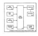
- FIG. 1is a block diagram showing the basic elements that comprise the combined physiological monitoring system (CPMS).
- CPMScombined physiological monitoring system
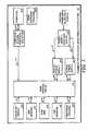
- FIG. 2is a detailed block diagram of the overall combined physiological monitoring system (CPMS).
- CPMScombined physiological monitoring system
- FIG. 3is a detailed block diagram of the CPMS control circuit which is integral element of the CPMS.
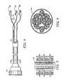
- FIG. 4is a side elevational view of an electromyography (EMG) cable assembly.
- EMGelectromyography
- FIG. 5is an elevational view of the multi-pin connector of the EMG cable assembly.
- FIG. 6is a sectional view of the EMG cable assembly taken along the lines 5 — 5 of FIG. 3 .
- FIG. 7is a module flow diagram of the CPMS spatent Data Acquisition System (PDAS) software program.
- PDASCPMS spatent Data Acquisition System
- the best mode for carrying out the inventionis presented in terms of a preferred embodiment for a combined physiological monitoring system (CPMS) 10 .
- the CPMSPerforms an electrodiagnostic functional assessment (EFA) by analyzing muscle activity by means of electromyography (EM).
- EAAelectrodiagnostic functional assessment
- EMelectromyography
- a standard silver—silver chloride electrodeis attached to a muscle or muscle group. The electrical activity of the muscle or muscle group is measured and recorded.
- the muscle groups monitored by the CPMS 10are: cervical, thoraic, upper extremity, lower extremity and lumbosacral. Data pertaining to each muscle group is typically taken in the following five steps, while the monitored muscle or muscle group is:
- the above testallow the CPMS 10 to determine muscle tone (contracture amplitude) muscle spasms (frequency) blood flow to muscles (vasoconstrive states), muscle activity (frequency and recruitment patterns), and muscle responses (fatigue).
- the CPMScan assess the condition and the dynamic functions of any particular muscle or muscle group.
- the CPMS 10is comprised of:
- EMSsurface electromyography
- ADCanalog-to-digital converter
- NVMnerve conductive velocity
- the electrodiagnostic functional assessmentcan be conducted one test at a time or can be combined with EMG, ROM, FCE and the grip and pinch strengths to provide an integrated test, which is conducted during a single test session.
- the CPMS 10can also be configured to function as an electrocardiagram (EKG) and to allow additional physiological functions to be added such as temperature, heart rate and skin response.
- EKGelectrocardiagram
- the CPMSis modified by using only eight channel(s).
- the EKG Provided by the CPMSis better because there is no movement artifact and can simultaneously monitor blood flow.
- the preferred embodiment of the CPMS 10is comprised of the following major elements: a CPMS control circuit 14 , a leads-off circuit 50 , an EMG sensor 52 , a range of motion (ROM) arm 54 , functional capacity evaluation (FCE) sensors 56 , a grip and a pinch sensor 58 , a power supply interface circuit 62 , an analog power supply 64 , a digital power supply 66 , an EMG cable assembly 70 , a patient data acquisition system (PDAS) software program 80 which resides in a PC computer 62 , and a computer/system interface circuit 84 .
- a CPMS control circuit 14a leads-off circuit 50 , an EMG sensor 52 , a range of motion (ROM) arm 54 , functional capacity evaluation (FCE) sensors 56 , a grip and a pinch sensor 58 , a power supply interface circuit 62 , an analog power supply 64 , a digital power supply 66 , an EMG cable assembly 70 , a patient data acquisition system (PDAS
- the CPMS control circuit 14has means for processing the digital and analog signals which operate the CPMS 10 .
- the circuit 14which is shown in its overall relationship with the CPMS 10 in FIG. 2 and in detail in FIG. 3, is partitioned into an analog section 16 , a digital section 40 and a power distribution circuit 48 .
- the analog section 16is comprised of an electromyography (EMG) leads connection circuit 18 , an EMG front end circuit 20 , a leads-off detection circuit 22 , a leads-off display circuit 24 , a range of motion (ROM)/functional capacity evaluation (FCE)/grip and pinch interface circuit 26 , a ROM front end circuit 28 , an FCE/grip and pinch front end circuit 30 , and a data acquisition circuit 34 .
- EMGelectromyography
- ROMrange of motion
- FCEfunctional capacity evaluation
- the EMG leads connection circuit 18has means for determining the structural integrity of the leads from the EMG sensors 52 , and can accommodate from one to nineteen leads.
- the circuit 18is connected to a first signal, a second signal and a third signal.
- the first signalis connected to the EMG sensor 52 and the second signal is connected to the EMG front end circuit 20 which has means for assessing the muscle activity sensed by the EMG sensors 52 .
- the circuit 20produces a fourth signal that is applied to the data acquisition circuit 34 for further processing.
- the third signal from the circuit 18is connected to the leads-off detection circuit 22 , which has means for determining if the EMG sensor leads are properly attached by measuring the impedance of the muscle and the surrounding skin area.
- the circuit 22is also connected to a fifth, sixth and seventh signal.
- the fifth signalis applied to the data acquisition circuit 34 for further processing
- the seventh signalis connected to the EMG sensors 52
- the sixth signalis applied to the leads-off display circuit 24 which has means for producing a display when an electrode attached to a muscle or the surrounding skin area is not properly attached. This determination is made by measuring the impedance of each electrode. If the impedance is not at a correct level, a corresponding LED illuminates.
- the circuit 24allows up to 32 electrodes to be utilized, wherein each electrode pertains to a specific muscle placement.
- the circuit 24which functions in combination with the circuit 22 , is connected to the circuit 22 Via the sixth signal.
- the range of motion (ROM)/functional capacity evaluation FCE/grip and pinch interface circuit 26is shown as a single element for purposes of explanation.
- the circuit 26is connected to an eighth, ninth and tenth signal which are connected respectively to a ROM sensor 54 , a plurality of FCE sensors 56 and a grip and pinch sensor 58 , which are further described infra.
- the circuit 26also produces an eleventh signal which is applied to the ROM front end circuit 28 and a twelfth signal applied to the FCE/grip and pinch front end circuit 30 .
- the ROM front end circuit 28has means for receiving and processing the data applied from the circuit 26 via the eleventh signal. The received data is amplified and filtered prior to producing a thirteenth digital signal that is applied to the data acquisition circuit 34 for further processing.
- the FCE/grip and pinch front end circuit 30has means for receiving and processing the data applied from the circuit 26 Via the twelfth signal.
- the received datais amplified and filtered prior to producing a fourteenth digital signal that is applied to the data acquisition circuit 34 for further processing.
- the data acquisition circuit 34is designed to include a first DAQ module 34 A and a second DAQ module 34 B.
- the DAQ modulesfunction in combination to receive the fourth signal from the circuit 20 , the fifth signal from the circuit 22 , the thirteenth signal from the circuit 28 and the fourteenth signal from the circuit 30 .
- the input signalsare processed by the circuit 34 to produce a fifteenth digital signal that is applied to the digital section 40 for further processing as shown in FIG. 3 .
- the digital section 40 of the CPMS control circuit 14is comprised of an optical isolation circuit 42 , a date processing circuit 44 and a computer interface circuit 46 .
- the optical isolation circuit 42has means for isolating a person from external electrical power sources which may harm a person and can cause erroneous test readings.
- the circuit 42is connected to the data acquisition circuit 34 via the fifteenth signal, to the data processing circuit 44 via a seventeenth signal, and to the computer interface circuit 46 via an eighteenth signal.
- the circuit 42also has connected a sixteenth digital power signal.
- the data processing circuit 44which is designed to process, transfer and store data, is also connected to the computer interface circuit 46 via a nineteenth signal.
- the computer interface circuit 46is also connected to a twenty-sixth signal, as shown in FIGS. 2 and 3, that is applied from the computer/system interface circuit 84 which interfaces with the computer 82 via a twenty-fifth signal.
- the circuit 46can be designed to operate with a Universal Serial BUS (USB), a Firewire (IEEE 1394) bus or a parallel port.
- the circuit 46is designed to interface with the software 80 via the computer 82 .
- the final element of the CPMS control circuit 14is the power distribution circuit 48 , which is applied a twenty second analog power signal and a twenty-fourth digital power signal as shown in FIG. 2 .
- the circuit 48has means for regulating and distributing digital power to the digital circuits in the CPMS control circuit 14 via the optical isolation circuit 42 , which is applied the sixteenth signal from the circuit 48 .
- the circuit 48also applies analog power to the analog section 16 of the CPMS control circuit 14 via a twentieth signal.
- the preferred embodiment of the overall combined physiological monitoring system (CPMS) 10is shown in FIG. 2, which includes the signal inputs applied to the CPMS control circuit 14 as described above.
- the first signal applied to the circuit 14is from the leads-off circuit 50 , which includes a means for determining if an electrode is not properly attached to a muscle.
- the first signalis sent sequentially to the circuit 18 and 22 , and to the leads-off display circuit 24 where an improperly-attached lead is displayed and a signal is sent to the software 80 to shut off the CPMS 10 .
- the EMG sensors 52produce the seventh signal which is applied to the leads-off detection circuit 22 in the CPMS circuit 14 .
- the EMS sensors 52sense the amplitude and frequency of various muscles or muscle groups. This data is used to monitor muscle, EKG or blood flow activity.
- the range of motion (ROM) arm 54includes a means for measuring the range of motion in the cervical, thoracic, lumbosacral, upper extremity, lower extremity and digits.
- the RON arm 54measures a person's lateral movement, flexion, extension and rotation, each having six degrees of freedom.
- the ROM arm 54incorporates two triaxial, silicon, micromatched accelerometer systems, wherein each system includes three hermetically-sealed ADXL05 accelerometers.
- the device 54has a bandwidth of 1 kHz to 4 kHz and, if required, can be a-c coupled.
- the ROM arm 54can be designed with precision potentiometers having three joints for monitoring segmental changes plus range of motion. All the analog data collected is converted to a d-c signal that is applied via an eighth signal to the ROM interface circuit 26 located in the CPMS control circuit 14 .
- the functional capacity evaluation (FCE) sensors 56include a means for measuring a person's lift, pull and push capability.
- the FCE sensorfunction by utilizing load cells which convert an analog signal produced by the sensors to a corresponding digital signal that is applied via a ninth signal to the FCE interface circuit 26 located in the CPMS control circuit 14 .
- the grip/pinch sensors 58include a means for measuring a person's hand grip strength and pinch strength.
- the hand grip strengthis measured by a load sensor that produces an analog signal proportional to the grip force.
- the analog grip force signalis converted by an ADO to a corresponding digital signal that is applied via a tenth signal to a grip interface circuit 26 located in the CPMS control circuit 14 .
- the pinch strengthis comprised of a load button-load cell.
- the load button-load cellwhich has a range of 0 to 50 lbs, is placed between the thumb and index finger and squeezed to produce an analog signal which is likewise converted to a digital signal that is applied, via the tenth signal, a pinch interface circuit 26 , also located in the CPMS control circuit 14 .
- the power input to the CPMS 10is provided by an external power source that is applied to a power supply interface circuit 62 .
- the circuit 62has means for receiving and processing a power input ranging from 120-250 volts at a frequency of 50 or 60 Hz.
- the circuit 62which incorporates circuit protection in the form of a circuit breaker or fuse, produces a twenty-first analog power signal and a twenty-third digital power signal.
- the analog powers supply 64which is connected to the twenty-first signal, produces a twenty-second output signal consisting of a regulated 5-volts d-c which powers the analog circuits in the CPMS control circuit 14 .
- the digital power supply 66which is isolated from the analog power supply 64 , is connected to the twenty-third signal and produces a twenty-fourth output signal consisting of a regulated 5-volt d-c which powers the CPMS 10 .
- the EMG cable assembly 70is designed to connect the EMG sensors to the muscle or muscle group of a person being tested.
- the cable 70includes a multi-pin connector 72 , as shown in FIGS. 4 and 5, ten shielded wire pairs 74 , as shown in FIG. 6, and three EMG electrodes 76 , 77 and 78 , as shown in FIG. 4 .
- the first electrode 76is active and is common with the second electrode 77 which is also active.
- the third electrode 78attaches to circuit ground.
- the EMG cable assembly 70incorporates a separation bar 79 , as shown in FIG. 4, which can be locked at a distance between 3 to 5 inches.
- the separation bar 79allows the two active electrodes 76 , 77 to remain isolated from each other.
- the EMG cable assembly 70can be designed to include a temperature sensor (not shown) which allows temperature readings to be taken in combination with other EMG sensor readings.
- the Patient Data Acquisition system (PDAS) software program 90is designed to provide control and data collection for the combined Physiological monitoring System (CPMS) 10 .
- the software 80provides error detection, interactive computer interface and resides in a dedicated PC computer 82 , which preferably consists of a laptop computer 82 which operates at least 400 MHz and has 64 to 256 megabytes of RAM. Additionally, the computer 82 incorporates at least a 10-gigabyte hard drive, a 14-inch active matrix LCD, an enhanced parallel port (EPP), a Universal Serial Bus (USB), a V.90 modem and 10baseT network cards.
- the operating systempreferably consists of Ms windows or Linux, and the overall design methodology is Booch's object oriented design (OOD).
- Thee computer 82is connected via a twenty-fifth signal to a computer/system interface circuit 84 which allots the computer 82 to communicate with the CPMS 10 via the CPMS control circuit 14 as shown in FIG. 1 .
- the software 80is comprised of nine major modules:
- PDAS Startprovides start up routines and initialization routines for the CPMS 10 .
- Upon startupa main window is displayed and user commands are concurrently sent to selected elements of the CPMS 10 .
- Select Patientprovides services to add a new patient, selects a previous patient for retest and selects a patient for demonstration, This module also calls Patient Info (described below) to collect patent information.
- Patient InfoProvides interactive forms for the collection of patient information. Five patient information forms are available: Info 1 , Info 2 , Info 3 , Info 4 and Info-note. After all data is validated, control is returned to the Select Patient module which then returns control to the PDAS 74 Start module.
- Select Protocolprovides control and message passing for eight specialized protocols and one custom protocol. Each protocol provides instructions to the patient and instructions on the placement of the EMG sensors. This module also provides support for the muscle groups: Cervical, thoraic, Upper Extremity, Lower Extremity, Lumbosacral, and chest.
- Acquireprovide data captures routines based on messages from the Select Protocol module via the PDAS Start module. Data is collected and monitored via the CPMS. If a lead fail is detected during the data capture, the Acquire module cancels the data capture and sends a warnings to the SelectProtocol module via the PDAS Start module. A successful data capture results in a data file being saved to a disk.
- ScanEMGprovides testing of the EMG channels. This module provides services to select a single channel or to select all channels for verification.
- TestPlotprovides a strip chart for testing all channels and their functions.
- EFAelectrodiagnostic functional assessment
- ROMrange of motion
- emeasures the foot muscle group by placing the ROM arm on the persons ankle, take measurements while the person is:
- the muscle groupsare classified as follows:
- the cervical muscle groupcomprises: sternocleidomastoid, scalene, paracervical, and upper trapzii,
- the thoraic muscle groupcomprises: mid trapezii, lower trapezii, paraspinal muscles T5-T8, T8-T12, terses, and seratus
- the lumbosacral muscle groupcomprises: paraspinal muscles L1-L3, L5-L51, quaratus lumborum, gluteal muscles, abdominal, and hamstrings,
- the lower extremities muscle groupcomprises: all muscles in pelvis, legs and feet,
- the foot muscle groupcomprises: all muscles in feet
- the upper extremities muscle groupcomprises: bilateral SCUM, scalene, deltoid, biceps, triceps and wrist flexors/extensors,
- the hand muscle groupcomprises: all muscles in the hands
- the face muscle groupcomprises: fontalis, massater TMJ
Landscapes
- Health & Medical Sciences (AREA)
- Life Sciences & Earth Sciences (AREA)
- Physics & Mathematics (AREA)
- Molecular Biology (AREA)
- Animal Behavior & Ethology (AREA)
- Pathology (AREA)
- Engineering & Computer Science (AREA)
- Biomedical Technology (AREA)
- Heart & Thoracic Surgery (AREA)
- Medical Informatics (AREA)
- Veterinary Medicine (AREA)
- Surgery (AREA)
- Biophysics (AREA)
- General Health & Medical Sciences (AREA)
- Public Health (AREA)
- Neurology (AREA)
- Neurosurgery (AREA)
- Physiology (AREA)
- Physical Education & Sports Medicine (AREA)
- Geometry (AREA)
- Dentistry (AREA)
- Oral & Maxillofacial Surgery (AREA)
- Measurement And Recording Of Electrical Phenomena And Electrical Characteristics Of The Living Body (AREA)
Abstract
Description
| U.S. Pat. No. | INVENTOR | ISSUED |
| 5,513,651 | Cusimano, et al | 7 May 1996 |
| 5,462,065 | Cusimano, et al | 31 Oct. 1995 |
| 5,042,505 | Mayer, et al | 27 Aug. 1991 |
| 4,688,581 | Moss | 25 Aug. 1987 |
| 4,667,513 | Konno | 26 May 1987 |
| U.S. Pat. No. | INVENTOR | ISSUED |
| 5,056,530 | Butler, et al | 15 Oct. 1991 |
| 5,050,618 | Larsen | 24 Sep. 1991 |
| 5,042,505 | Meyer, et al | 27 Aug. 1991 |
| 5,038,795 | Roush, et al | 13 Aug. 1991 |
| 5,012,820 | Meyer | 7 May 1991 |
| 4,938,476 | Brunell, et al | 3 Jul. 1990 |
| 4,928,709 | Allison, et al | 29 May 1990 |
| 4,886,073 | Dillion, et al | 12 Dec. 1989 |
| 4,845,987 | Kenneth | 11 Jul. 1989 |
| 4,834,057 | McLeod, Jr. | 30 May 1989 |
| 4,805,636 | Barry, et al | 21 Feb. 1989 |
| 4,800,897 | Nilsson | 31 Jan. 1989 |
| 4,742,832 | Kauffmann, et al | 10 May 1988 |
| 4,667,513 | Konno | 26 May 1987 |
| 4,586,515 | Berger | 6 May 1986 |
Claims (30)
Priority Applications (1)
| Application Number | Priority Date | Filing Date | Title |
|---|---|---|---|
| US10/002,942US6678549B2 (en) | 2001-03-26 | 2001-11-15 | Combined physiological monitoring system |
Applications Claiming Priority (3)
| Application Number | Priority Date | Filing Date | Title |
|---|---|---|---|
| USPCT/US01/09418 | 2001-03-26 | ||
| PCT/US2001/009418WO2002076293A1 (en) | 2001-03-26 | 2001-03-26 | Combined physiological monitoring system |
| US10/002,942US6678549B2 (en) | 2001-03-26 | 2001-11-15 | Combined physiological monitoring system |
Publications (2)
| Publication Number | Publication Date |
|---|---|
| US20030135129A1 US20030135129A1 (en) | 2003-07-17 |
| US6678549B2true US6678549B2 (en) | 2004-01-13 |
Family
ID=26671055
Family Applications (1)
| Application Number | Title | Priority Date | Filing Date |
|---|---|---|---|
| US10/002,942Expired - LifetimeUS6678549B2 (en) | 2001-03-26 | 2001-11-15 | Combined physiological monitoring system |
Country Status (1)
| Country | Link |
|---|---|
| US (1) | US6678549B2 (en) |
Cited By (42)
| Publication number | Priority date | Publication date | Assignee | Title |
|---|---|---|---|---|
| US20030149379A1 (en)* | 1999-12-22 | 2003-08-07 | Tensor B.V. | Methods for treatment and prevention of disorders resulting from hypertension of neck and shoulder muscles |
| US20040113498A1 (en)* | 2002-12-12 | 2004-06-17 | Thomas Kroenke | Electrical isolation interface for medical instrumentation |
| WO2005055815A3 (en)* | 2003-12-09 | 2005-08-25 | Univ State San Diego | Systems and methods for dynamic analysis of muscle function and metabolism |
| US20060100546A1 (en)* | 2004-11-10 | 2006-05-11 | Silk Jeffrey E | Self-contained real-time gait therapy device |
| US20070015611A1 (en)* | 2005-07-13 | 2007-01-18 | Ultimate Balance, Inc. | Orientation and motion sensing in athletic training systems, physical rehabilitation and evaluation systems, and hand-held devices |
| US20070085690A1 (en)* | 2005-10-16 | 2007-04-19 | Bao Tran | Patient monitoring apparatus |
| US20070148624A1 (en)* | 2005-12-23 | 2007-06-28 | Avinoam Nativ | Kinesthetic training system with composite feedback |
| US20070265533A1 (en)* | 2006-05-12 | 2007-11-15 | Bao Tran | Cuffless blood pressure monitoring appliance |
| US20070276270A1 (en)* | 2006-05-24 | 2007-11-29 | Bao Tran | Mesh network stroke monitoring appliance |
| US20080004904A1 (en)* | 2006-06-30 | 2008-01-03 | Tran Bao Q | Systems and methods for providing interoperability among healthcare devices |
| US20080200827A1 (en)* | 2005-05-11 | 2008-08-21 | Charles Dean Cyphery | Apparatus For Converting Electromyographic (Emg) Signals For Transference to a Personal Computer |
| US20080221398A1 (en)* | 2004-05-25 | 2008-09-11 | Ronchi Andrew J | Apparatus and Method for Monitoring and/or Load Applied to a Mammal |
| US20080288200A1 (en)* | 2007-05-18 | 2008-11-20 | Noble Christopher R | Newtonian physical activity monitor |
| US20080294019A1 (en)* | 2007-05-24 | 2008-11-27 | Bao Tran | Wireless stroke monitoring |
| US7502498B2 (en) | 2004-09-10 | 2009-03-10 | Available For Licensing | Patient monitoring apparatus |
| US7539533B2 (en) | 2006-05-16 | 2009-05-26 | Bao Tran | Mesh network monitoring appliance |
| US7593769B1 (en) | 2006-02-14 | 2009-09-22 | Iq Biolabs, Inc. | Surface electromyography index |
| US20090259413A1 (en)* | 2003-04-09 | 2009-10-15 | Loadstar Sensors, Inc. | Resistive force sensing device and method with an advanced communication interface |
| US20100145219A1 (en)* | 2008-12-10 | 2010-06-10 | Iq Biolabs, Inc. | Stations for performing physiological stress tests |
| RU2417740C2 (en)* | 2009-01-29 | 2011-05-10 | Государственное образовательное учреждение высшего профессионального образования "Северный государственный медицинский университет" (г. Архангельск) Федерального агентства по здравоохранению и социальному развитию" "ГОУ ВПО СГМУ Росздрава" | Method for detecting neuroreflex reactions of finger skin vessels in patients with anterior scalene muscle syndrome |
| US20110201904A1 (en)* | 2010-02-18 | 2011-08-18 | Mary Rose Cusimano Reaston | Electro diagnostic functional assessment unit (EFA-2) |
| US20110224503A1 (en)* | 2010-03-12 | 2011-09-15 | Cusimano Reaston Maryrose | Electro diagnostic functional assessment unit (EFA-3) |
| US8082786B1 (en)* | 2004-01-15 | 2011-12-27 | Robert Akins | Work capacities testing apparatus and method |
| US8117047B1 (en)* | 2007-04-16 | 2012-02-14 | Insight Diagnostics Inc. | Healthcare provider organization |
| WO2012051628A1 (en)* | 2010-10-15 | 2012-04-19 | Lgch, Inc. | Method and apparatus for detecting seizures |
| US20120130202A1 (en)* | 2010-11-24 | 2012-05-24 | Fujitsu Limited | Diagnosis and Monitoring of Musculoskeletal Pathologies |
| US8323189B2 (en) | 2006-05-12 | 2012-12-04 | Bao Tran | Health monitoring appliance |
| US8461988B2 (en) | 2005-10-16 | 2013-06-11 | Bao Tran | Personal emergency response (PER) system |
| US8500636B2 (en) | 2006-05-12 | 2013-08-06 | Bao Tran | Health monitoring appliance |
| US8684922B2 (en) | 2006-05-12 | 2014-04-01 | Bao Tran | Health monitoring system |
| US8684900B2 (en) | 2006-05-16 | 2014-04-01 | Bao Tran | Health monitoring appliance |
| US8752428B2 (en) | 2004-01-15 | 2014-06-17 | Robert Akins | Work capacities testing apparatus and method |
| US8928671B2 (en) | 2010-11-24 | 2015-01-06 | Fujitsu Limited | Recording and analyzing data on a 3D avatar |
| US8968195B2 (en) | 2006-05-12 | 2015-03-03 | Bao Tran | Health monitoring appliance |
| US9060683B2 (en) | 2006-05-12 | 2015-06-23 | Bao Tran | Mobile wireless appliance |
| US9186105B2 (en) | 2011-07-05 | 2015-11-17 | Brain Sentinel, Inc. | Method and apparatus for detecting seizures |
| US9782624B2 (en) | 2015-02-03 | 2017-10-10 | Kiio Inc. | Interchangeable grip and pinch strength assessor and exerciser |
| US9865176B2 (en) | 2012-12-07 | 2018-01-09 | Koninklijke Philips N.V. | Health monitoring system |
| US10045730B2 (en) | 2014-09-11 | 2018-08-14 | The Mitre Corporation | Methods and systems for rapid screening of mild traumatic brain injury |
| US10226209B2 (en) | 2010-10-15 | 2019-03-12 | Brain Sentinel, Inc. | Method and apparatus for classification of seizure type and severity using electromyography |
| US10610148B2 (en) | 2015-04-17 | 2020-04-07 | Brain Sentinel, Inc. | Method of monitoring a patient for seizure activity |
| US10736525B2 (en) | 2016-04-19 | 2020-08-11 | Brain Sentinel, Inc. | Systems and methods for characterization of seizures |
Families Citing this family (27)
| Publication number | Priority date | Publication date | Assignee | Title |
|---|---|---|---|---|
| US8346367B2 (en) | 2002-09-11 | 2013-01-01 | Meagan Medical, Inc. | Apparatus and method for stabilizing, improving mobility, and controlling cartilage matrix degradation of weight-bearing articular joints |
| US8060210B1 (en)* | 2002-09-11 | 2011-11-15 | International Rehabilitative Sciences, Inc. | Methods for improving mobility and controlling cartilage matrix degradation of weight-bearing articular joints |
| US7182738B2 (en)* | 2003-04-23 | 2007-02-27 | Marctec, Llc | Patient monitoring apparatus and method for orthosis and other devices |
| WO2005006956A2 (en)* | 2003-07-09 | 2005-01-27 | Medical Technologies Unlimited, Inc. | Comprehensive neuromuscular profiler |
| US8187209B1 (en)* | 2005-03-17 | 2012-05-29 | Great Lakes Neurotechnologies Inc | Movement disorder monitoring system and method |
| US7844340B2 (en)* | 2007-01-31 | 2010-11-30 | Pawlowicz Iii John S | Devices and methods for transcutaneous electrical neural stimulation |
| US8260425B2 (en)* | 2007-10-12 | 2012-09-04 | Intelect Medical, Inc. | Deep brain stimulation system with inputs |
| JP2011519684A (en) | 2008-05-05 | 2011-07-14 | マシモ コーポレイション | Pulse oximeter system with electrical disconnect circuit |
| US11557073B2 (en) | 2008-06-02 | 2023-01-17 | Precision Biometrics, Inc. | System for generating medical diagnostic images |
| AU2009256441B2 (en)* | 2008-06-02 | 2013-06-13 | Precision Biometrics, Inc. | Systems and methods for performing surface electromyography and range-of-motion tests |
| EP2358450A4 (en)* | 2008-12-03 | 2015-09-09 | Hilla Sarig-Bahat | Motion assessment system and method |
| US9106038B2 (en) | 2009-10-15 | 2015-08-11 | Masimo Corporation | Pulse oximetry system with low noise cable hub |
| WO2011069122A1 (en) | 2009-12-04 | 2011-06-09 | Masimo Corporation | Calibration for multi-stage physiological monitors |
| US20120143064A1 (en)* | 2010-11-05 | 2012-06-07 | Charles Dean Cyphery | Muscle function evaluating system |
| CN103190924B (en)* | 2012-01-09 | 2014-12-17 | 上海理工大学 | Portable sitting and standing function evaluation and training device |
| ES2425293B1 (en)* | 2012-03-09 | 2014-08-25 | Universidad De Zaragoza | DEVICE AND METHOD FOR THE ASSESSMENT OF FUNCTIONAL CAPACITY |
| JP2017512115A (en)* | 2014-03-12 | 2017-05-18 | モビューティーク アグシャセルスガーッブMovotec A/S | Muscle stiffness measurement system, apparatus, and method |
| US20160100775A1 (en)* | 2014-10-12 | 2016-04-14 | Mary Reaston | Integrated Movement Assessment System |
| CN104490390B (en)* | 2014-12-30 | 2017-03-08 | 天津大学 | Human Stamina method of discrimination based on the analysis of Electrophysiology combined signal |
| TWI598073B (en)* | 2016-12-15 | 2017-09-11 | 財團法人工業技術研究院 | Physiological signal measurement method and physiological signal measurement device |
| CN108261197A (en)* | 2018-03-19 | 2018-07-10 | 上海理工大学 | Upper limb healing evaluation system and method based on surface myoelectric and motion module |
| US11446191B2 (en) | 2019-04-19 | 2022-09-20 | Hill-Rom Services, Inc. | Patient bed having exercise therapy apparatus |
| US20210174929A1 (en)* | 2019-12-06 | 2021-06-10 | The Boeing Company | Soft tissue material cumulative damage model for reducing repetitive stress injuries in performing a process |
| US12300376B2 (en) | 2021-01-21 | 2025-05-13 | The Boeing Company | Characterizing soft tissue stress for ameliorating injury in performing a process |
| AU2022268224A1 (en) | 2021-04-27 | 2023-12-14 | The Boeing Company | Combining multiple ergonomic risk factors in a single predictive finite element model |
| US12144684B2 (en) | 2021-09-01 | 2024-11-19 | The Boeing Company | Characterizing soft tissue subrupture damage and incomplete tear damage for performing a process |
| US20240115855A1 (en)* | 2022-10-06 | 2024-04-11 | Mary Reaston | System For Management Of Musculoskeletal Disorders |
Citations (3)
| Publication number | Priority date | Publication date | Assignee | Title |
|---|---|---|---|---|
| US5513651A (en)* | 1994-08-17 | 1996-05-07 | Cusimano; Maryrose | Integrated movement analyzing system |
| US5885231A (en)* | 1997-01-07 | 1999-03-23 | The General Hospital Corporation | Digital motor event recording system |
| US6152855A (en)* | 1999-02-03 | 2000-11-28 | Synergy Innovations, Inc. | In-bed exercise machine and method of use |
- 2001
- 2001-11-15USUS10/002,942patent/US6678549B2/ennot_activeExpired - Lifetime
Patent Citations (3)
| Publication number | Priority date | Publication date | Assignee | Title |
|---|---|---|---|---|
| US5513651A (en)* | 1994-08-17 | 1996-05-07 | Cusimano; Maryrose | Integrated movement analyzing system |
| US5885231A (en)* | 1997-01-07 | 1999-03-23 | The General Hospital Corporation | Digital motor event recording system |
| US6152855A (en)* | 1999-02-03 | 2000-11-28 | Synergy Innovations, Inc. | In-bed exercise machine and method of use |
Cited By (91)
| Publication number | Priority date | Publication date | Assignee | Title |
|---|---|---|---|---|
| US7074198B2 (en)* | 1999-12-22 | 2006-07-11 | Tensor, B.V. | Methods for treatment and prevention of disorders resulting from hypertension of neck and shoulder muscles |
| US20030149379A1 (en)* | 1999-12-22 | 2003-08-07 | Tensor B.V. | Methods for treatment and prevention of disorders resulting from hypertension of neck and shoulder muscles |
| US20040113498A1 (en)* | 2002-12-12 | 2004-06-17 | Thomas Kroenke | Electrical isolation interface for medical instrumentation |
| US20090259413A1 (en)* | 2003-04-09 | 2009-10-15 | Loadstar Sensors, Inc. | Resistive force sensing device and method with an advanced communication interface |
| WO2005055815A3 (en)* | 2003-12-09 | 2005-08-25 | Univ State San Diego | Systems and methods for dynamic analysis of muscle function and metabolism |
| US8082786B1 (en)* | 2004-01-15 | 2011-12-27 | Robert Akins | Work capacities testing apparatus and method |
| US9439594B2 (en)* | 2004-01-15 | 2016-09-13 | Robert Akins | Work capacities testing apparatus and method |
| US20140295391A1 (en)* | 2004-01-15 | 2014-10-02 | Robert Akins | Work Capacities Testing Apparatus and Method |
| US8752428B2 (en) | 2004-01-15 | 2014-06-17 | Robert Akins | Work capacities testing apparatus and method |
| US8167799B2 (en) | 2004-05-25 | 2012-05-01 | Andrew J Ronchi | Apparatus and method for monitoring strain and/or load applied to a mammal |
| US20080221398A1 (en)* | 2004-05-25 | 2008-09-11 | Ronchi Andrew J | Apparatus and Method for Monitoring and/or Load Applied to a Mammal |
| US7502498B2 (en) | 2004-09-10 | 2009-03-10 | Available For Licensing | Patient monitoring apparatus |
| US7648441B2 (en) | 2004-11-10 | 2010-01-19 | Silk Jeffrey E | Self-contained real-time gait therapy device |
| US20060100546A1 (en)* | 2004-11-10 | 2006-05-11 | Silk Jeffrey E | Self-contained real-time gait therapy device |
| US20080200827A1 (en)* | 2005-05-11 | 2008-08-21 | Charles Dean Cyphery | Apparatus For Converting Electromyographic (Emg) Signals For Transference to a Personal Computer |
| US7383728B2 (en) | 2005-07-13 | 2008-06-10 | Ultimate Balance, Inc. | Orientation and motion sensing in athletic training systems, physical rehabilitation and evaluation systems, and hand-held devices |
| US20070015611A1 (en)* | 2005-07-13 | 2007-01-18 | Ultimate Balance, Inc. | Orientation and motion sensing in athletic training systems, physical rehabilitation and evaluation systems, and hand-held devices |
| US7420472B2 (en) | 2005-10-16 | 2008-09-02 | Bao Tran | Patient monitoring apparatus |
| US8747336B2 (en) | 2005-10-16 | 2014-06-10 | Bao Tran | Personal emergency response (PER) system |
| US8461988B2 (en) | 2005-10-16 | 2013-06-11 | Bao Tran | Personal emergency response (PER) system |
| US20070085690A1 (en)* | 2005-10-16 | 2007-04-19 | Bao Tran | Patient monitoring apparatus |
| US8531291B2 (en) | 2005-10-16 | 2013-09-10 | Bao Tran | Personal emergency response (PER) system |
| US7365647B2 (en)* | 2005-12-23 | 2008-04-29 | Avinoam Nativ | Kinesthetic training system with composite feedback |
| US20070148624A1 (en)* | 2005-12-23 | 2007-06-28 | Avinoam Nativ | Kinesthetic training system with composite feedback |
| US7593769B1 (en) | 2006-02-14 | 2009-09-22 | Iq Biolabs, Inc. | Surface electromyography index |
| US8708903B2 (en) | 2006-05-12 | 2014-04-29 | Bao Tran | Patient monitoring appliance |
| US20070265533A1 (en)* | 2006-05-12 | 2007-11-15 | Bao Tran | Cuffless blood pressure monitoring appliance |
| US8968195B2 (en) | 2006-05-12 | 2015-03-03 | Bao Tran | Health monitoring appliance |
| US7539532B2 (en) | 2006-05-12 | 2009-05-26 | Bao Tran | Cuffless blood pressure monitoring appliance |
| US8652038B2 (en) | 2006-05-12 | 2014-02-18 | Bao Tran | Health monitoring appliance |
| US9215980B2 (en) | 2006-05-12 | 2015-12-22 | Empire Ip Llc | Health monitoring appliance |
| US8747313B2 (en) | 2006-05-12 | 2014-06-10 | Bao Tran | Health monitoring appliance |
| US9801542B2 (en) | 2006-05-12 | 2017-10-31 | Koninklijke Philips N.V. | Health monitoring appliance |
| US8727978B2 (en) | 2006-05-12 | 2014-05-20 | Bao Tran | Health monitoring appliance |
| US9820657B2 (en) | 2006-05-12 | 2017-11-21 | Koninklijke Philips N.V. | Mobile wireless appliance |
| US8684922B2 (en) | 2006-05-12 | 2014-04-01 | Bao Tran | Health monitoring system |
| US8500636B2 (en) | 2006-05-12 | 2013-08-06 | Bao Tran | Health monitoring appliance |
| US9060683B2 (en) | 2006-05-12 | 2015-06-23 | Bao Tran | Mobile wireless appliance |
| US8328718B2 (en) | 2006-05-12 | 2012-12-11 | Bao Tran | Health monitoring appliance |
| US8425415B2 (en) | 2006-05-12 | 2013-04-23 | Bao Tran | Health monitoring appliance |
| US8475368B2 (en) | 2006-05-12 | 2013-07-02 | Bao Tran | Health monitoring appliance |
| US8323189B2 (en) | 2006-05-12 | 2012-12-04 | Bao Tran | Health monitoring appliance |
| US8684900B2 (en) | 2006-05-16 | 2014-04-01 | Bao Tran | Health monitoring appliance |
| US8323188B2 (en) | 2006-05-16 | 2012-12-04 | Bao Tran | Health monitoring appliance |
| US9028405B2 (en) | 2006-05-16 | 2015-05-12 | Bao Tran | Personal monitoring system |
| US7539533B2 (en) | 2006-05-16 | 2009-05-26 | Bao Tran | Mesh network monitoring appliance |
| US9107586B2 (en) | 2006-05-24 | 2015-08-18 | Empire Ip Llc | Fitness monitoring |
| US8449471B2 (en) | 2006-05-24 | 2013-05-28 | Bao Tran | Health monitoring appliance |
| US7558622B2 (en) | 2006-05-24 | 2009-07-07 | Bao Tran | Mesh network stroke monitoring appliance |
| US20070276270A1 (en)* | 2006-05-24 | 2007-11-29 | Bao Tran | Mesh network stroke monitoring appliance |
| US8764651B2 (en) | 2006-05-24 | 2014-07-01 | Bao Tran | Fitness monitoring |
| US10307060B2 (en) | 2006-06-30 | 2019-06-04 | Koninklijke Philips N.V. | Mesh network personal emergency response appliance |
| US8525673B2 (en) | 2006-06-30 | 2013-09-03 | Bao Tran | Personal emergency response appliance |
| US10729336B1 (en) | 2006-06-30 | 2020-08-04 | Bao Tran | Smart watch |
| US10610111B1 (en) | 2006-06-30 | 2020-04-07 | Bao Tran | Smart watch |
| US10517479B2 (en) | 2006-06-30 | 2019-12-31 | Koninklijke Philips N.V. | Mesh network personal emergency response appliance |
| US11051704B1 (en) | 2006-06-30 | 2021-07-06 | Bao Tran | Smart watch |
| US9204796B2 (en) | 2006-06-30 | 2015-12-08 | Empire Ip Llc | Personal emergency response (PER) system |
| US11696682B2 (en) | 2006-06-30 | 2023-07-11 | Koninklijke Philips N.V. | Mesh network personal emergency response appliance |
| US9901252B2 (en) | 2006-06-30 | 2018-02-27 | Koninklijke Philips N.V. | Mesh network personal emergency response appliance |
| US8525687B2 (en) | 2006-06-30 | 2013-09-03 | Bao Tran | Personal emergency response (PER) system |
| US9820658B2 (en) | 2006-06-30 | 2017-11-21 | Bao Q. Tran | Systems and methods for providing interoperability among healthcare devices |
| US20080004904A1 (en)* | 2006-06-30 | 2008-01-03 | Tran Bao Q | Systems and methods for providing interoperability among healthcare devices |
| US9775520B2 (en) | 2006-06-30 | 2017-10-03 | Empire Ip Llc | Wearable personal monitoring system |
| US9351640B2 (en) | 2006-06-30 | 2016-05-31 | Koninklijke Philips N.V. | Personal emergency response (PER) system |
| US8117047B1 (en)* | 2007-04-16 | 2012-02-14 | Insight Diagnostics Inc. | Healthcare provider organization |
| US7634379B2 (en) | 2007-05-18 | 2009-12-15 | Ultimate Balance, Inc. | Newtonian physical activity monitor |
| US20080288200A1 (en)* | 2007-05-18 | 2008-11-20 | Noble Christopher R | Newtonian physical activity monitor |
| US20080294019A1 (en)* | 2007-05-24 | 2008-11-27 | Bao Tran | Wireless stroke monitoring |
| US8750971B2 (en) | 2007-05-24 | 2014-06-10 | Bao Tran | Wireless stroke monitoring |
| US9549691B2 (en) | 2007-05-24 | 2017-01-24 | Bao Tran | Wireless monitoring |
| US20100145219A1 (en)* | 2008-12-10 | 2010-06-10 | Iq Biolabs, Inc. | Stations for performing physiological stress tests |
| US8126542B2 (en) | 2008-12-10 | 2012-02-28 | Somaxis, Inc. | Methods for performing physiological stress tests |
| RU2417740C2 (en)* | 2009-01-29 | 2011-05-10 | Государственное образовательное учреждение высшего профессионального образования "Северный государственный медицинский университет" (г. Архангельск) Федерального агентства по здравоохранению и социальному развитию" "ГОУ ВПО СГМУ Росздрава" | Method for detecting neuroreflex reactions of finger skin vessels in patients with anterior scalene muscle syndrome |
| US20110201904A1 (en)* | 2010-02-18 | 2011-08-18 | Mary Rose Cusimano Reaston | Electro diagnostic functional assessment unit (EFA-2) |
| US8535224B2 (en) | 2010-02-18 | 2013-09-17 | MaryRose Cusimano Reaston | Electro diagnostic functional assessment unit (EFA-2) |
| US8568312B2 (en) | 2010-03-12 | 2013-10-29 | MaryRose Cusimano Reaston | Electro diagnostic functional assessment unit (EFA-3) |
| US20110224503A1 (en)* | 2010-03-12 | 2011-09-15 | Cusimano Reaston Maryrose | Electro diagnostic functional assessment unit (EFA-3) |
| US8983591B2 (en) | 2010-10-15 | 2015-03-17 | Brain Sentinel, Inc. | Method and apparatus for detecting seizures |
| US10226209B2 (en) | 2010-10-15 | 2019-03-12 | Brain Sentinel, Inc. | Method and apparatus for classification of seizure type and severity using electromyography |
| AU2011315819B2 (en)* | 2010-10-15 | 2014-12-11 | Brain Sentinel, Inc. | Method and apparatus for detecting seizures |
| WO2012051628A1 (en)* | 2010-10-15 | 2012-04-19 | Lgch, Inc. | Method and apparatus for detecting seizures |
| US20120130202A1 (en)* | 2010-11-24 | 2012-05-24 | Fujitsu Limited | Diagnosis and Monitoring of Musculoskeletal Pathologies |
| US8928671B2 (en) | 2010-11-24 | 2015-01-06 | Fujitsu Limited | Recording and analyzing data on a 3D avatar |
| US9186105B2 (en) | 2011-07-05 | 2015-11-17 | Brain Sentinel, Inc. | Method and apparatus for detecting seizures |
| US9865176B2 (en) | 2012-12-07 | 2018-01-09 | Koninklijke Philips N.V. | Health monitoring system |
| US10045730B2 (en) | 2014-09-11 | 2018-08-14 | The Mitre Corporation | Methods and systems for rapid screening of mild traumatic brain injury |
| US10874343B2 (en) | 2014-09-11 | 2020-12-29 | The Mitre Corporation | Methods and systems for rapid screening of mild traumatic brain injury |
| US9782624B2 (en) | 2015-02-03 | 2017-10-10 | Kiio Inc. | Interchangeable grip and pinch strength assessor and exerciser |
| US10610148B2 (en) | 2015-04-17 | 2020-04-07 | Brain Sentinel, Inc. | Method of monitoring a patient for seizure activity |
| US10736525B2 (en) | 2016-04-19 | 2020-08-11 | Brain Sentinel, Inc. | Systems and methods for characterization of seizures |
Also Published As
| Publication number | Publication date |
|---|---|
| US20030135129A1 (en) | 2003-07-17 |
Similar Documents
| Publication | Publication Date | Title |
|---|---|---|
| US6678549B2 (en) | Combined physiological monitoring system | |
| US8535224B2 (en) | Electro diagnostic functional assessment unit (EFA-2) | |
| US8568312B2 (en) | Electro diagnostic functional assessment unit (EFA-3) | |
| US5513651A (en) | Integrated movement analyzing system | |
| US5462065A (en) | Integrated movement analyziing system | |
| Netto et al. | Reliability of normalisation methods for EMG analysis of neck muscles | |
| US8323190B2 (en) | Comprehensive neuromuscular profiler | |
| US6280395B1 (en) | System and method for determining muscle dysfunction | |
| Clancy et al. | Relating agonist-antagonist electromyograms to joint torque during isometric, quasi-isotonic, nonfatiguing contractions | |
| US4444205A (en) | Apparatus for assessing joint mobility | |
| US9402579B2 (en) | Real-time assessment of absolute muscle effort during open and closed chain activities | |
| KR102421547B1 (en) | Muscular deficiency diagnosis platform and muscle deficiency analysis method using the same | |
| JPH08501713A (en) | How to measure the effects of joints and related muscles | |
| Pulkovski et al. | Tissue Doppler imaging for detecting onset of muscle activity | |
| WO2002076293A1 (en) | Combined physiological monitoring system | |
| Norasi et al. | Development and assessment of a method to estimate the value of a maximum voluntary isometric contraction electromyogram from submaximal electromyographic data | |
| Riemer et al. | Effect of familiarization on the reproducibility of maximum isometric normalization contractions in a worker-specific sample | |
| US20040138583A1 (en) | Sincerity index system and program therefor | |
| Chen et al. | Direct measurement of elbow joint angle using galvanic couple system | |
| Deepashini et al. | Reliability study of plantar pressure measurement among low back pain patients carrying different loads | |
| De Boer et al. | Reliability of dynamometry in patients with a neuromuscular disorder | |
| Morozumi et al. | A new tissue hardness meter and algometer; a new meter incorporating the functions of a tissue hardness meter and an algometer | |
| Cenkovich et al. | A quantitative electromyographic index that is independent of the force of contraction | |
| AU711074B2 (en) | An integrated movement analyzing system | |
| Shankhwar et al. | Effect of Muscle Fatigue on Heart Signal on Physical Activity with Electromyogram and Electrocardiogram Monitoring Signals |
Legal Events
| Date | Code | Title | Description |
|---|---|---|---|
| AS | Assignment | Owner name:REASTON, PHIL, NEVADA Free format text:ASSIGNMENT OF ASSIGNORS INTEREST;ASSIGNOR:CUSIMANO, MARYROSE;REEL/FRAME:014029/0537 Effective date:20030523 | |
| STCF | Information on status: patent grant | Free format text:PATENTED CASE | |
| AS | Assignment | Owner name:INSIGHT DIAGNOSTICS INC., NEVADA Free format text:ASSIGNMENT OF ASSIGNORS INTEREST;ASSIGNOR:REASTON, PHIL;REEL/FRAME:016630/0995 Effective date:20051013 | |
| REMI | Maintenance fee reminder mailed | ||
| FPAY | Fee payment | Year of fee payment:4 | |
| SULP | Surcharge for late payment | ||
| FPAY | Fee payment | Year of fee payment:8 | |
| AS | Assignment | Owner name:OKTX, LLC, OKLAHOMA Free format text:ASSIGNMENT OF ASSIGNORS INTEREST;ASSIGNOR:IDI-DX, INC., F/K/A INSIGHT DIAGNOSTICS, INC.;REEL/FRAME:029993/0677 Effective date:20120618 | |
| REMI | Maintenance fee reminder mailed | ||
| FPAY | Fee payment | Year of fee payment:12 | |
| SULP | Surcharge for late payment | Year of fee payment:11 | |
| AS | Assignment | Owner name:WESTERN ALLIANCE BANK, AN ARIZONA CORPORATION, CAL Free format text:SECURITY INTEREST;ASSIGNOR:EMERGE DIAGNOSTICS, INC.;REEL/FRAME:045755/0034 Effective date:20180509 | |
| AS | Assignment | Owner name:EMERGE DIAGNOSTICS INC., CALIFORNIA Free format text:RELEASE BY SECURED PARTY;ASSIGNOR:WESTERN ALLIANCE BANK;REEL/FRAME:067184/0920 Effective date:20240410 |