US6678496B1 - Skive mechanism for reproduction apparatus fuser rollers - Google Patents
Skive mechanism for reproduction apparatus fuser rollersDownload PDFInfo
- Publication number
- US6678496B1 US6678496B1US10/216,985US21698502AUS6678496B1US 6678496 B1US6678496 B1US 6678496B1US 21698502 AUS21698502 AUS 21698502AUS 6678496 B1US6678496 B1US 6678496B1
- Authority
- US
- United States
- Prior art keywords
- skive
- fuser apparatus
- receiver member
- finger
- pin
- Prior art date
- Legal status (The legal status is an assumption and is not a legal conclusion. Google has not performed a legal analysis and makes no representation as to the accuracy of the status listed.)
- Expired - Lifetime
Links
Images


Classifications
- G—PHYSICS
- G03—PHOTOGRAPHY; CINEMATOGRAPHY; ANALOGOUS TECHNIQUES USING WAVES OTHER THAN OPTICAL WAVES; ELECTROGRAPHY; HOLOGRAPHY
- G03G—ELECTROGRAPHY; ELECTROPHOTOGRAPHY; MAGNETOGRAPHY
- G03G15/00—Apparatus for electrographic processes using a charge pattern
- G03G15/20—Apparatus for electrographic processes using a charge pattern for fixing, e.g. by using heat
- G03G15/2003—Apparatus for electrographic processes using a charge pattern for fixing, e.g. by using heat using heat
- G03G15/2014—Apparatus for electrographic processes using a charge pattern for fixing, e.g. by using heat using heat using contact heat
- G03G15/2017—Structural details of the fixing unit in general, e.g. cooling means, heat shielding means
- G03G15/2028—Structural details of the fixing unit in general, e.g. cooling means, heat shielding means with means for handling the copy material in the fixing nip, e.g. introduction guides, stripping means
- Y—GENERAL TAGGING OF NEW TECHNOLOGICAL DEVELOPMENTS; GENERAL TAGGING OF CROSS-SECTIONAL TECHNOLOGIES SPANNING OVER SEVERAL SECTIONS OF THE IPC; TECHNICAL SUBJECTS COVERED BY FORMER USPC CROSS-REFERENCE ART COLLECTIONS [XRACs] AND DIGESTS
- Y10—TECHNICAL SUBJECTS COVERED BY FORMER USPC
- Y10S—TECHNICAL SUBJECTS COVERED BY FORMER USPC CROSS-REFERENCE ART COLLECTIONS [XRACs] AND DIGESTS
- Y10S271/00—Sheet feeding or delivering
- Y10S271/90—Stripper
Definitions
- the present inventionrelates in general to a skive mechanism for stripping receiver members from fuser apparatus rollers of reproduction apparatus, and more particularly to a skive mechanism including a contact skive assembly and an air skive for fuser apparatus rollers which will substantially prevent damage to the rollers and to the fused image on the receiver members stripped from the rollers.
- a latent image charge patternis formed on a uniformly charged dielectric member. Pigmented marking particles are attracted to the latent image charge pattern to develop such image on the dielectric member.
- a receiver memberis then brought into contact with the dielectric member.
- An electric fieldsuch as provided by a corona charger or an electrically biased roller, is applied to transfer the marking particle developed image to the receiver member from the dielectric member.
- the receiver member bearing the transferred imageis separated from the dielectric member and transported away from the dielectric member to a fuser apparatus at a downstream location. There the image is fixed to the receiver member by heat and/or pressure from the fuser apparatus to form a permanent reproduction on the receiver member.
- One type of fuser apparatusutilized in typical reproduction apparatus, includes at least one heated roller and at least one pressure roller in nip relation with the heated roller.
- the fuser apparatus rollersare rotated to transport a receiver member, bearing a marking particle image, through the nip between the rollers.
- the pigmented marking particles of the transferred image on the surface of the receiver membersoften and become tacky in the heat. Under the pressure, the softened tacky marking particles attach to each other and are partially imbibed into the interstices of the fibers at the surface of the receiver member.
- the marking particle imageis permanently fixed to the receiver member. It sometimes happens that the marking particles stick to the peripheral surface of the heated roller and result in the receiver member adhering to such roller; or the marking particles may stick to the heated roller and subsequently transfer to the peripheral surface of the pressure roller resulting in a receiver member adhering to the pressure roller.
- a skive mechanismincluding mechanical skive fingers or separator pawls for example, has been employed to engage the respective peripheral surfaces of the fuser apparatus rollers to strip any adhering receiver member from the rollers in order to substantially prevent receiver member jams in the fuser apparatus.
- a fuser apparatus skive mechanismincludes a plurality of skive fingers.
- the skive fingersare generally formed as elongated members respectively having a relatively sharp leading edge urged into engagement with a fuser apparatus roller.
- the skive fingersmay be thin, relatively flexible, metal shim stock.
- the respective leading edge of each of the skive fingersis directed in the opposite direction to rotation of the fuser apparatus roller with which such skive finger is associated so as to act like a chisel to strip any receiver member adhering to such roller from the peripheral surface thereof.
- the receiver membermay adhere to a fuser apparatus roller with such force that engagement with the skive fingers does not completely strip the receiver member from the roller.
- the receiver memberwill cause a jam in the fuser apparatus. This destroys the reproduction formed on the receiver member and shuts down the reproduction apparatus until the receiver member is cleared from the fuser apparatus.
- the stripped portions of the receiver memberare forced into engagement with their associated skive fingers by the non-stripped portions of the receiver member.
- the engagement force of the receiver member on the skive fingersmay be sufficient to flex those skive fingers so as to engage the associated peripheral surface of the fuser apparatus roller at a substantially increased attack angle. This increased attack angle may then damage the roller by gouging its peripheral surface or may damage the skive finger itself. Alternatively, as the receiver member is transported through the fuser apparatus, the receiver member may apply such force to the skive fingers on initial engagement therewith so as to cause such fingers to buckle in the direction which will flex those skive fingers to engage the associated fuser apparatus roller at an increased attack angle. Again, this increased attack angle may damage the roller by gouging its peripheral surface or may damage the skive finger itself.
- Another skive mechanismwhich can overcome problems generated by mechanical skive fingers, includes air jets directed at the rollers to strip any adhering receiver member from the rollers (see for example U.S. Pat. No. 4,420,152 (issued Dec. 13, 1983, in the name of Miyashita). It provides an air chamber with exhaust nozzles which direct escaping air at high speeds for separating receiver members from the fuser rollers.
- air jetsdirected at the rollers to strip any adhering receiver member from the rollers.
- this inventionis directed to a fuser apparatus having a pair of rollers in nip relation to transport a receiver member therebetween to permanently fix a marking particle image to such receiver member, and a skive mechanism for stripping a receiver member adhering to a fuser apparatus roller from the said roller.
- the skive mechanismincludes a frame located in spaced relation with one of the rollers of the pair of fuser apparatus rollers.
- a plurality of skive assemblies, mounted on the frameeach include a skive finger and a support body for supporting such skive finger in operative relation to such one of the rollers.
- the skive fingersare elongated, thin, flexible members to substantially prevent damage to such associated fuser apparatus roller.
- an air plenumis provided in operative relation to the other of the pair of rollers of the fuser apparatus rollers.
- the air plenumhas a nozzle arrangement directed at an angle to the fuser apparatus roller associated with the air plenum so as to provide a positive air flow to substantially assure that a receiver member adhering to such fuser apparatus roller is stripped therefrom.
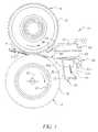
- FIG. 1is a side elevational view of a reproduction apparatus fuser having a receiver member skive assembly, according to this invention, with portions removed or broken away to facilitate viewing;
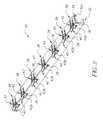
- FIG. 2is a view, in perspective, of the receiver member skive assembly of FIG. 1, with portions removed or broken away to facilitate viewing;
- FIG. 3is a top plan view, on an enlarged scale, of a receiver member skive finger from the skive assembly, according to this invention, as shown in FIG. 1;
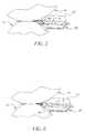
- FIGS. 4, 5 , 6 , and 7are respective side elevational views of the receiver member skive assembly, similar to that shown in FIG. 1, showing removal of various modes of for jammed sheets;
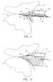
- FIG. 8is a side elevational view, on an enlarged scale, of the receiver member skive assembly, similar to that shown in FIG. 1, showing the air flow created thereby;
- FIG. 9is a side elevational view, on an enlarged scale, of the receiver member skive assembly, similar to that shown in FIG. 8 with a receiver member jam being removed from the fuser nip;
- FIG. 10is a side elevational view, on an enlarged scale, of an alternate embodiment of the receiver member skive assembly, according to this invention, to improve air flow therethrough;
- FIG. 11is a side elevational view, on an enlarged scale, of the alternate receiver member skive assembly, according to this invention, similar to that shown in FIG. 10, with a receiver member being skived from a fuser roller;
- FIG. 12is a front elevational view, on an enlarged scale, of the receiver member skive assembly, according to this invention, similar to that shown in FIG. 10, with a receiver member being skived from a fuser roller;
- FIG. 13is a side elevational view, on an enlarged scale, of another alternate embodiment of the receiver member skive assembly, according to this invention, showing a slide support therefor;
- FIG. 14is a side elevational view, on an enlarged scale, of the alternate receiver member skive assembly, according to this invention, as shown in FIG. 13, showing finger stops;
- FIG. 15is a side elevational view, on an enlarged scale, of yet another alternate embodiment of the receiver member skive assembly, according to this invention.
- FIGS. 16-18are side elevational views, on an enlarged scale, of the alternate receiver member skive assembly according to this invention, as shown in FIG. 15, respectively showing operating conditions thereof.
- FIG. 1shows a typical fuser apparatus, designated generally by the numeral 10 , for a common commercial electrographic reproduction apparatus.
- the fuser apparatus 10includes a fuser roller 12 in nip relation with a pressure roller 14 . Rotation of the fuser rollers by any suitable drive mechanism (not shown) will serve to transport a receiver member (designated for example by the letter R in FIG. 1 ), bearing a marking particle image I, through the nip under the application of heat and pressure.
- the receiver membermay be, for example, a sheet of plain bond paper, or transparency material.
- the heatwill soften the marking particles and the pressure will force the particles into intimate contact with each other and with the surface of the receiver material, such that the particles are at least partially imbibed into the receiver material fibers.
- the marking particlescool, they are permanently fixed to the receiver member in an image-wise fashion.
- the fuser roller 12includes a core 16 with a cylindrical fusing blanket 18 supported on the core.
- the blanket 18is typically made of a rubber material particularly formulated to be heat conductive or heat insulative depending upon whether the fuser heat source is located within the core 16 or in juxtaposition with the periphery of the blanket.
- the heat sourceis an internal heater lamp designated by the numeral 20 .
- a well known suitable surface coatingmay be applied to the blanket 18 to substantially prevent offsetting of the marking particle image to the fuser roller 12 .
- the pressure roller 14has a hard outer shell 22 .
- the shell 22is made of metal, such as aluminum or steel for example.
- the shell 22may also have a well known suitable surface coating (not shown) applied thereto to substantially prevent offsetting of the marking particle image to the pressure roller 14 .
- a cleaning assembly(not shown) may be provided to remove residual marking particle, paper fibers, and dust from the fuser apparatus rollers.
- a skive mechanismdesignated generally by the numeral 30 , is provided according to this invention.
- the skive mechanism 30shown in FIG. 1 in operative relation with the fuser roller 12 , includes a frame 32 having a portion 32 a mounted on a pivot rod 34 .
- the pivot rod 34has its longitudinal axis parallel to the longitudinal axis of the fuser roller 12 , and extends for a length substantially equal to the length of the fuser roller.
- the frame 32defines a plurality of openings 36 for a plurality of skive finger assemblies 38 respectively (see FIG. 2 ).
- a resilient member 44(see FIG. 1 ), such as a coil spring, urges the frame 32 in a direction about the pivot rod 34 to maintain the skive assemblies of the skive mechanism in operative engagement with the fuser roller.
- Each skive finger assembly 38includes a skive finger 40 and a skive finger support 42 .
- the skive finger 40is formed as an elongated, substantially planar, relatively flexible element having a sharp chisel-like leading edge (for example, formed from a thin metal sheet).
- the skive finger support 42is formed as a main body having features for capturing and supporting a skive finger.
- the body of the skive finger support 42includes a slot 42 a and a lead edge 42 b .
- the slot 42 ais adapted to be received on the pivot rod 34 to locate each skive finger support 42 adjacent to a respective opening 36 such that the skive fingers 40 extend through the openings toward the fuser roller 12 .
- the action of the resilient member 44causes the lead edge of the skive finger 40 to contact the fuser roller, and the lead edge 42 b to be normally spaced from the fuser roller 12 .
- the skive finger support 42will pivot about the rod 34 until the lead edge 42 a of the support engages the fuser roller 12 .
- the skive fingers 40are of a particular preferred configuration best suited for engaging the roller of the fuser apparatus 10 which is relatively softer than the other nip-forming roller such that the nip shape is curved around the harder roller. Therefore, the receiver member on the exit from the nip is forced away from the skive finger-bearing softer roller.
- the thin flexible fingerscould be placed very close to the nip (preferably 2 to 5 millimeters) under very low tip load (2 to 10 grams).
- the preferred skive fingersare long (free span 25 to 40 mms) and thin (0.1 to 0.13 mms).
- skive fingers 40are very thin, therefore, it is possible to place them very close to the fuser roller nip, and further when combined with the softer skive finger-bearing roller enables the skive fingers to work as guides rather than strippers for the receiver. Furthermore, when the skive fingers 40 are used as receiver member guides, a high tip force is not needed and thus roller surface damage is avoided. Such a skive finger arrangement works best when the harder roller of the fuser nip rollers has an air knife 50 (see FIG. 1) for the receiver release from its surface.
- the air knife 50(see FIG. 1) includes an air plenum 52 having a nozzle arrangement 54 .
- the air knifeis located in a particular relation to the skive finger assemblies 38 such that the air knife is in operative relation to the roller nip of the fuser apparatus 10 .
- the air plenum 52is in flow communication with a pressurized air source P.
- the nozzle arrangement 54includes a plurality of nozzle jets 56 (only one shown in the drawings) which are aligned parallel to an element of the pressure roller 14 .
- the jets 56are directed at an angle to the pressure roller 14 so as to provide a positive air flow to strip a receiver member adhering to the pressure roller therefrom.
- FIGS. 4, 5 , 6 , and 7various possible receiver member jam modes are depicted.
- FIG. 4an accordion type jam is represented; in FIG. 5, an underneath jam is depicted; in FIG. 6, a buckle-up jam is shown; and in FIG. 7, a buckle-down jam is represented.
- FIG. 4An accordion type jam is represented; in FIG. 5, an underneath jam is depicted; in FIG. 6, a buckle-up jam is shown; and in FIG. 7, a buckle-down jam is represented.
- These possible receiver member jam scenarioswere all tested, and no surface damage to either of the fuser apparatus rollers or to the skive fingers was noticed.
- the fuser apparatus roller wear and gouging problemis accordingly obviated by the very flexible, thin, long skive fingers 40 . This is due to the fact that the skive fingers according to this invention tend to buckle under much less force than the force which would damage the surfaces of the fuser apparatus rollers.
- FIGS. 8 and 9the effect of the air flow from the air knife 50 is shown. While the air knife 50 serves to substantially avoid skive marks on reproductions, FIG. 8 shows the turbulent air flow of the deflected high pressure air between the air knife and the skive fingers 40 which form a receiver member guide plate with the support body 42 . The effect of this deflected turbulent air flow on a receiver member is shown in FIG. 9 .
- the receiver memberafter the release from the roller 14 by airflow from the high pressure air jet 56 , is deflected down towards the roller 12 and guided outwards from the fuser apparatus 10 by the skive fingers 40 and the guide plate they form with the support body 42 .
- FIGS. 10-12show an alternate embodiment of the air knife, designated by the numeral 50 ′, for overcoming the aforementioned problems caused by high friction forces and turbulent air flow.
- the support members 42 ′ for the skive fingers 40 ′together forming the receiver member guide plate, are configured to provide an extended flow path for deflected air.
- the support member 42 ′includes a plurality of low friction fins 58 on either side of respective skive fingers (see FIG. 12 ). Accordingly, on exiting the fuser apparatus roller nip, the receiver member R′ (FIGS. 11 and 12) is guided and transported over the low friction fins 58 .
- the fins 58not only reduce the friction forces that oppose the receiver member motion, but also corrugate the receiver member in the cross-track direction (i.e., the direction transverse to the travel direction).
- the corrugationserves to impart a greater degree of stiffness to the receiver member, and thus the transportation of the receiver member is very smooth as it glides over the low friction fins (waves and cockles in the receiver member are substantially prevented).
- FIGS. 13 and 14show an alternate embodiment of the skive assembly, designated by the numeral 30 ′′, which further serves to substantially prevent gouging of the fuser apparatus roller by the skive fingers.
- Each of the skive assemblies 30 ′′has a slide mechanism 60 .
- the slide mechanism 60includes a mounting shaft 62 having a clevis 62 a at one end mounted on a pin 64 for rotation about the longitudinal axis of such pin.
- the pin 64is fixed in a bracket 66 connected to the frame 32 ′′ of the skive assembly 30 ′′.
- a linear guide 68is supported on the mounting shaft 62 , in suitable linear bearings 70 , so as to enable the linear guide to move linearly on the mounting shaft.
- the linear guide 68is urged by a coil spring 72 , for example, into engagement with the clevis 62 a to properly locate the linear guide under normal operating circumstances.
- a respective skive finger 40 ′′ and support body 42 ′′are fixed to the linear guide 68 via a pin 74 . Accordingly, when a skive finger 40 ′′ is engaged by a receiver member and a jam condition occurs, the linear guide 68 is capable of moving linearly on the mounting shaft 62 , against the urging of the spring 72 , and can pivot about the pin 64 .
- the force of the receiver member on the skive fingers 40 ′′causes the linear guide 68 of the slide mechanism 60 to slide, and also rotate (change the tilt angle about pin 64 ) when the linear guide is retracting back or sliding, to thus clear the skive fingers from the associated fuser apparatus roller.
- the movement of the skive fingers due to rotation of the linear guide 68 about the pin 64is restricted by a stopper pin 76 and a stopper plate 78 (see FIG. 14 ).
- the skive fingersare stopped by the stopper plate 78 , thus not allowing the skive fingers to pivot (clockwise in the drawings) to an extent sufficient to touch the upper roller, while enough force is generated by the jammed receiver member to push the linear guide 68 away from the rollers.
- the skive fingersare stopped by the stopper pin 76 , thus not allowing the skive fingers to pivot (counter-clockwise in the drawings) to an extent sufficient to gouge the lower roller, while enough force is generated by the jammed receiver member to push the linear guide 68 away from the rollers.
- the slide mechanism 60is at an inclined plane (setting angle) so that enough force of the jammed receiver member is generated along the longitudinal axis of the mounting shaft 62 to make the slide mechanism (and thus the respective skive finger) move away from the fuser apparatus rollers during a receiver member jam irrespective of whether the jam is under or above the skive fingers.
- the skive assembly parametersi.e. the attack angle, the setting angle, and the tilt angle, are optimized based on the fuser apparatus roller size and the nip geometry.
- FIGS. 15-18demonstrate schematically the critical parameters and method for determining the preferred configuration for a further embodiment of the skive fingers designated 40 ′′′.
- the skive finger tip force (P)is determined by the deflection of the finger as it presses into the elastomer cover of the fuser apparatus roller 12 .
- the finger tip force (P)generates a friction force (F) due to the resistance between the skive finger and the roller as the roller rotates in the direction in opposition to the finger tip.
- the finger strength (S)should be greater than the friction force (F) (FIG. 16 ).
- Ffriction force
- an additional forcewould be generated which would make the friction force higher than the skive finger strength. Without the considerations of this invention, this would make the skive finger bend or dig into the fuser apparatus roller surface. Of course, such action would be detrimental in that either the skive finger or the roller surface would be damaged.
- the skive finger tip forceis reduced whenever the skive finger is pushed back due to an increased load (friction force) during receiver member jams or receiver members sticking to the skive fingers.
- the skive finger tip force reductionoccurs because the skive finger free length increases from L to L 1 (as shown in FIG. 15; L 1 >L). That is to say, the skive finger's normal free length L is measured from the tip of the skive finger to the mid-support point provided by a cross-pin 84 .
- the skive fingermoves such that it separates from the cross-pin 84 .
- the free length L for the calculationis measured from the tip of the skive finger to the screw connection 86 with the support body 42 ′′′.
- a bottom support 82 for the fingeris also provided to avoid large bending or buckling of the finger and thus reducing the chances of skive finger damage or roller surface gouging.
- the skive finger 40 ′′′is pressed against the fuser apparatus roller 12 and the cross-pin 84 to generate a predetermined tip force P (see FIG. 15 ).
- the skive finger 40 ′′′separates from the cross-pin 84 .
- the free span of the skive finger(as discussed above) will increase from L to L 1 (L 1 >L); therefore the skive finger tip force, as calculated by using the formula above, decreases because of the increased free length of the finger.
- the decrease in the skive finger tip forcewill decrease the frictional forces and consequently the finger will try to return to its original setting (see FIG. 17 ).
Landscapes
- Physics & Mathematics (AREA)
- General Physics & Mathematics (AREA)
- Separation, Sorting, Adjustment, Or Bending Of Sheets To Be Conveyed (AREA)
- Fixing For Electrophotography (AREA)
Abstract
Description
Claims (18)
Priority Applications (2)
| Application Number | Priority Date | Filing Date | Title |
|---|---|---|---|
| US10/216,985US6678496B1 (en) | 2002-08-12 | 2002-08-12 | Skive mechanism for reproduction apparatus fuser rollers |
| DE10332950ADE10332950A1 (en) | 2002-08-12 | 2003-07-18 | Scraper mechanism for fuser rollers in a duplicator |
Applications Claiming Priority (1)
| Application Number | Priority Date | Filing Date | Title |
|---|---|---|---|
| US10/216,985US6678496B1 (en) | 2002-08-12 | 2002-08-12 | Skive mechanism for reproduction apparatus fuser rollers |
Publications (1)
| Publication Number | Publication Date |
|---|---|
| US6678496B1true US6678496B1 (en) | 2004-01-13 |
Family
ID=29780283
Family Applications (1)
| Application Number | Title | Priority Date | Filing Date |
|---|---|---|---|
| US10/216,985Expired - LifetimeUS6678496B1 (en) | 2002-08-12 | 2002-08-12 | Skive mechanism for reproduction apparatus fuser rollers |
Country Status (2)
| Country | Link |
|---|---|
| US (1) | US6678496B1 (en) |
| DE (1) | DE10332950A1 (en) |
Cited By (19)
| Publication number | Priority date | Publication date | Assignee | Title |
|---|---|---|---|---|
| US20030165348A1 (en)* | 2002-03-01 | 2003-09-04 | Akiyasu Amita | Fixing device with a peeler and image forming apparatus including the same |
| US20040084838A1 (en)* | 2002-10-29 | 2004-05-06 | Susumu Murakami | Paper separator and processor cartridge |
| US20040146323A1 (en)* | 2002-11-07 | 2004-07-29 | Seiko Epson Corporation | Fixing device |
| US6892047B1 (en)* | 2002-09-25 | 2005-05-10 | Eastman Kodak Company | Air baffle for paper travel path within an electrophotographic machine |
| US20050260020A1 (en)* | 2004-05-21 | 2005-11-24 | Eastman Kodak Company | Skiving device and methods of use |
| US20050260916A1 (en)* | 2004-05-21 | 2005-11-24 | Eastman Kodak Company | Method of making an electronic display |
| US20050259215A1 (en)* | 2004-05-21 | 2005-11-24 | Eastman Kodak Company | Method of making an electronic display |
| US20050257811A1 (en)* | 2004-05-21 | 2005-11-24 | Eastman Kodak Company | Nozzle tip and methods of use |
| US20050259213A1 (en)* | 2004-05-21 | 2005-11-24 | Eastman Kodak Company | Method of making an electronic display |
| US20060000338A1 (en)* | 2004-05-21 | 2006-01-05 | Eastman Kodak Company | Roller and methods of use |
| US20070071512A1 (en)* | 2005-09-23 | 2007-03-29 | Xerox Corporation | Non-gouging sheet stripper assembly |
| US20080101830A1 (en)* | 2006-10-30 | 2008-05-01 | Seiko Epson Corporation | Post-Fixing Support Unit and Image Forming Apparatus Using the Same |
| US20090087234A1 (en)* | 2007-09-27 | 2009-04-02 | Xerox Corporation | Enhanced fuser stripping system |
| US20100158580A1 (en)* | 2008-12-19 | 2010-06-24 | Eastman Kodak Company | Metering skive for a developer roller |
| US20110079354A1 (en)* | 2009-10-07 | 2011-04-07 | Xerox Corporation | Apparatuses useful in printing, fixing devices and methods of stripping substrates from surfaces in apparatuses useful in printing |
| CN102193459A (en)* | 2010-03-19 | 2011-09-21 | 柯尼卡美能达商用科技株式会社 | Fixing device and image forming apparatus |
| US20130266351A1 (en)* | 2012-04-10 | 2013-10-10 | Konica Minolta Business Technologies, Inc. | Fixing unit and image forming apparatus |
| JP2016206511A (en)* | 2015-04-27 | 2016-12-08 | 京セラドキュメントソリューションズ株式会社 | Fixing apparatus and image forming apparatus having the same |
| JP2017016032A (en)* | 2015-07-03 | 2017-01-19 | キヤノン株式会社 | Image forming apparatus |
Citations (9)
| Publication number | Priority date | Publication date | Assignee | Title |
|---|---|---|---|---|
| US4806985A (en)* | 1986-07-11 | 1989-02-21 | Xerox Corporation | Stripper fingers |
| US4859831A (en)* | 1988-06-15 | 1989-08-22 | Xerox Corporation | Fuser system |
| US4866485A (en)* | 1988-09-19 | 1989-09-12 | Eastman Kodak Company | Molded skive and guide |
| US5448347A (en)* | 1994-04-28 | 1995-09-05 | Eastman Kodak Company | Fuser skive mount |
| US5589925A (en)* | 1994-11-08 | 1996-12-31 | Eastman Kodak Company | Anti-gouging skive mechanism with replaceable fingers |
| US5623720A (en)* | 1996-09-30 | 1997-04-22 | Xerox Corporation | Method and apparatus for stripper bar rotation |
| US6208827B1 (en)* | 1998-11-20 | 2001-03-27 | Eastman Kodak Company | Dual function air skive assembly for reproduction apparatus fuser rollers |
| US6295436B1 (en)* | 2000-09-27 | 2001-09-25 | Heidelberg Digital L.L.C. | Installation of lower skive plate in the fuser section of an electrophotographic machine |
| US6490428B1 (en)* | 2001-12-21 | 2002-12-03 | Xerox Corporation | Stripper fingers and associated mounts for a fuser in a printing apparatus |
- 2002
- 2002-08-12USUS10/216,985patent/US6678496B1/ennot_activeExpired - Lifetime
- 2003
- 2003-07-18DEDE10332950Apatent/DE10332950A1/ennot_activeWithdrawn
Patent Citations (9)
| Publication number | Priority date | Publication date | Assignee | Title |
|---|---|---|---|---|
| US4806985A (en)* | 1986-07-11 | 1989-02-21 | Xerox Corporation | Stripper fingers |
| US4859831A (en)* | 1988-06-15 | 1989-08-22 | Xerox Corporation | Fuser system |
| US4866485A (en)* | 1988-09-19 | 1989-09-12 | Eastman Kodak Company | Molded skive and guide |
| US5448347A (en)* | 1994-04-28 | 1995-09-05 | Eastman Kodak Company | Fuser skive mount |
| US5589925A (en)* | 1994-11-08 | 1996-12-31 | Eastman Kodak Company | Anti-gouging skive mechanism with replaceable fingers |
| US5623720A (en)* | 1996-09-30 | 1997-04-22 | Xerox Corporation | Method and apparatus for stripper bar rotation |
| US6208827B1 (en)* | 1998-11-20 | 2001-03-27 | Eastman Kodak Company | Dual function air skive assembly for reproduction apparatus fuser rollers |
| US6295436B1 (en)* | 2000-09-27 | 2001-09-25 | Heidelberg Digital L.L.C. | Installation of lower skive plate in the fuser section of an electrophotographic machine |
| US6490428B1 (en)* | 2001-12-21 | 2002-12-03 | Xerox Corporation | Stripper fingers and associated mounts for a fuser in a printing apparatus |
Cited By (37)
| Publication number | Priority date | Publication date | Assignee | Title |
|---|---|---|---|---|
| US20030165348A1 (en)* | 2002-03-01 | 2003-09-04 | Akiyasu Amita | Fixing device with a peeler and image forming apparatus including the same |
| US6813464B2 (en)* | 2002-03-01 | 2004-11-02 | Ricoh Company, Ltd. | Fixing device with a peeler and biasing devices and image forming apparatus including the same |
| US6892047B1 (en)* | 2002-09-25 | 2005-05-10 | Eastman Kodak Company | Air baffle for paper travel path within an electrophotographic machine |
| US7251450B2 (en)* | 2002-10-29 | 2007-07-31 | Sharp Kabushiki Kaisha | Paper separator and processor cartridge |
| US20040084838A1 (en)* | 2002-10-29 | 2004-05-06 | Susumu Murakami | Paper separator and processor cartridge |
| US7149463B2 (en)* | 2002-11-07 | 2006-12-12 | Seiko Epson Corporation | Fixing device |
| US20060291917A1 (en)* | 2002-11-07 | 2006-12-28 | Seiko Epson Corporation | Fixing device |
| US20040146323A1 (en)* | 2002-11-07 | 2004-07-29 | Seiko Epson Corporation | Fixing device |
| US7187896B2 (en) | 2002-11-07 | 2007-03-06 | Seiko Epson Corporation | Fixing device |
| US7485191B2 (en) | 2004-05-21 | 2009-02-03 | Industrial Technology Research Institute | Nozzle tip and methods of use |
| US20060000338A1 (en)* | 2004-05-21 | 2006-01-05 | Eastman Kodak Company | Roller and methods of use |
| US7024153B2 (en) | 2004-05-21 | 2006-04-04 | Eastman Kodak Company | Skiving device and methods of use |
| US20050260916A1 (en)* | 2004-05-21 | 2005-11-24 | Eastman Kodak Company | Method of making an electronic display |
| US20050259213A1 (en)* | 2004-05-21 | 2005-11-24 | Eastman Kodak Company | Method of making an electronic display |
| US20050257811A1 (en)* | 2004-05-21 | 2005-11-24 | Eastman Kodak Company | Nozzle tip and methods of use |
| US7685692B2 (en) | 2004-05-21 | 2010-03-30 | Industrial Technology Research Institute | Process for removing material from a substrate |
| US7245346B2 (en) | 2004-05-21 | 2007-07-17 | Eastman Kodak Company | Method of making an electronic display |
| US20050260020A1 (en)* | 2004-05-21 | 2005-11-24 | Eastman Kodak Company | Skiving device and methods of use |
| US20050259215A1 (en)* | 2004-05-21 | 2005-11-24 | Eastman Kodak Company | Method of making an electronic display |
| US7310491B2 (en)* | 2005-09-23 | 2007-12-18 | Xerox Corporation | Non-gouging sheet stripper assembly |
| US20070071512A1 (en)* | 2005-09-23 | 2007-03-29 | Xerox Corporation | Non-gouging sheet stripper assembly |
| US7672628B2 (en)* | 2006-10-30 | 2010-03-02 | Seiko Epson Corporation | Post-fixing support unit and image forming apparatus using the same |
| US20080101830A1 (en)* | 2006-10-30 | 2008-05-01 | Seiko Epson Corporation | Post-Fixing Support Unit and Image Forming Apparatus Using the Same |
| US20090087234A1 (en)* | 2007-09-27 | 2009-04-02 | Xerox Corporation | Enhanced fuser stripping system |
| US7676187B2 (en)* | 2007-09-27 | 2010-03-09 | Xerox Corporation | Enhanced fuser stripping system |
| US8145104B2 (en) | 2008-12-19 | 2012-03-27 | Eastman Kodak Company | Metering skive for a developer roller |
| US20100158580A1 (en)* | 2008-12-19 | 2010-06-24 | Eastman Kodak Company | Metering skive for a developer roller |
| US20110079354A1 (en)* | 2009-10-07 | 2011-04-07 | Xerox Corporation | Apparatuses useful in printing, fixing devices and methods of stripping substrates from surfaces in apparatuses useful in printing |
| US8408270B2 (en)* | 2009-10-07 | 2013-04-02 | Xerox Corporation | Apparatuses useful in printing, fixing devices and methods of stripping substrates from surfaces in apparatuses useful in printing |
| US20110229220A1 (en)* | 2010-03-19 | 2011-09-22 | Koji Yamamoto | Fixing device and image forming apparatus |
| CN102193459A (en)* | 2010-03-19 | 2011-09-21 | 柯尼卡美能达商用科技株式会社 | Fixing device and image forming apparatus |
| US8583017B2 (en)* | 2010-03-19 | 2013-11-12 | Konica Minolta Business Technologies, Inc. | Fixing device including an air separation section |
| CN102193459B (en)* | 2010-03-19 | 2014-10-08 | 柯尼卡美能达商用科技株式会社 | Fixing device and image forming apparatus |
| US20130266351A1 (en)* | 2012-04-10 | 2013-10-10 | Konica Minolta Business Technologies, Inc. | Fixing unit and image forming apparatus |
| US8942608B2 (en)* | 2012-04-10 | 2015-01-27 | Konica Minolta Business Technologies, Inc. | Fixing unit and image forming apparatus |
| JP2016206511A (en)* | 2015-04-27 | 2016-12-08 | 京セラドキュメントソリューションズ株式会社 | Fixing apparatus and image forming apparatus having the same |
| JP2017016032A (en)* | 2015-07-03 | 2017-01-19 | キヤノン株式会社 | Image forming apparatus |
Also Published As
| Publication number | Publication date |
|---|---|
| DE10332950A1 (en) | 2004-02-26 |
Similar Documents
| Publication | Publication Date | Title |
|---|---|---|
| US6678496B1 (en) | Skive mechanism for reproduction apparatus fuser rollers | |
| JP3386235B2 (en) | Transfer paper guide device | |
| US5532810A (en) | Fuser roller skive mechanism having anti-gouging skive fingers | |
| US5589925A (en) | Anti-gouging skive mechanism with replaceable fingers | |
| JP2004212954A (en) | Peeling device, and fixing device and image forming apparatus using the same | |
| US5517292A (en) | Fusing apparatus having a paper separating unit | |
| EP1333339B1 (en) | Stripper fingers and associated mounts for a xerographic fusing apparatus | |
| US20040067079A1 (en) | Stripper fingers and roller assembly for a fuser in a printing apparatus | |
| US20020044803A1 (en) | Image heating apparatus for heating image formed on recording material | |
| US6029039A (en) | Retractable contact skive assembly for reproduction apparatus fuser rollers | |
| JP4666585B2 (en) | Image forming apparatus | |
| US6735412B2 (en) | Capillary micro-groove skive fingers | |
| US6208827B1 (en) | Dual function air skive assembly for reproduction apparatus fuser rollers | |
| US5822668A (en) | Fuser subsystem module for an electrophotographic printer which pivots open for jam clearance | |
| US4561756A (en) | Short paper path copy sheet transport system | |
| US20160349677A1 (en) | Fixing device and image forming apparatus | |
| US7890037B2 (en) | Self adjusting metal stripper fingers | |
| US6104000A (en) | Dual function air skive assembly for reproduction apparatus fuser rollers | |
| US5708946A (en) | Fuser skive mechanism mounting for facilitating jam clearance | |
| US5231457A (en) | Method and apparatus for preventing attraction of a work sheet to a toner image forming surface | |
| JPH0328438Y2 (en) | ||
| JP2003270995A (en) | Fixing device and image forming device | |
| JP4773927B2 (en) | Sheet discharging apparatus and image forming apparatus | |
| US7013572B1 (en) | Skive plate assembly | |
| JP2018010221A (en) | Image forming apparatus |
Legal Events
| Date | Code | Title | Description |
|---|---|---|---|
| AS | Assignment | Owner name:NEXPRESS SOLUTIONS LLC, NEW YORK Free format text:ASSIGNMENT OF ASSIGNORS INTEREST;ASSIGNORS:ASLAM, MUHAMMED;MIURA, TSUTOMU;WU, FANGSHENG;REEL/FRAME:013353/0745;SIGNING DATES FROM 20020822 TO 20020910 | |
| FEPP | Fee payment procedure | Free format text:PAYOR NUMBER ASSIGNED (ORIGINAL EVENT CODE: ASPN); ENTITY STATUS OF PATENT OWNER: LARGE ENTITY | |
| STCF | Information on status: patent grant | Free format text:PATENTED CASE | |
| AS | Assignment | Owner name:EASTMAN KODAK COMPANY, NEW YORK Free format text:ASSIGNMENT OF ASSIGNORS INTEREST;ASSIGNOR:NEXPRESS SOLUTIONS, INC. (FORMERLY NEXPRESS SOLUTIONS LLC);REEL/FRAME:015928/0176 Effective date:20040909 | |
| FPAY | Fee payment | Year of fee payment:4 | |
| FPAY | Fee payment | Year of fee payment:8 | |
| AS | Assignment | Owner name:CITICORP NORTH AMERICA, INC., AS AGENT, NEW YORK Free format text:SECURITY INTEREST;ASSIGNORS:EASTMAN KODAK COMPANY;PAKON, INC.;REEL/FRAME:028201/0420 Effective date:20120215 | |
| AS | Assignment | Owner name:WILMINGTON TRUST, NATIONAL ASSOCIATION, AS AGENT, MINNESOTA Free format text:PATENT SECURITY AGREEMENT;ASSIGNORS:EASTMAN KODAK COMPANY;PAKON, INC.;REEL/FRAME:030122/0235 Effective date:20130322 Owner name:WILMINGTON TRUST, NATIONAL ASSOCIATION, AS AGENT, Free format text:PATENT SECURITY AGREEMENT;ASSIGNORS:EASTMAN KODAK COMPANY;PAKON, INC.;REEL/FRAME:030122/0235 Effective date:20130322 | |
| AS | Assignment | Owner name:BANK OF AMERICA N.A., AS AGENT, MASSACHUSETTS Free format text:INTELLECTUAL PROPERTY SECURITY AGREEMENT (ABL);ASSIGNORS:EASTMAN KODAK COMPANY;FAR EAST DEVELOPMENT LTD.;FPC INC.;AND OTHERS;REEL/FRAME:031162/0117 Effective date:20130903 Owner name:BARCLAYS BANK PLC, AS ADMINISTRATIVE AGENT, NEW YORK Free format text:INTELLECTUAL PROPERTY SECURITY AGREEMENT (SECOND LIEN);ASSIGNORS:EASTMAN KODAK COMPANY;FAR EAST DEVELOPMENT LTD.;FPC INC.;AND OTHERS;REEL/FRAME:031159/0001 Effective date:20130903 Owner name:JPMORGAN CHASE BANK, N.A., AS ADMINISTRATIVE, DELAWARE Free format text:INTELLECTUAL PROPERTY SECURITY AGREEMENT (FIRST LIEN);ASSIGNORS:EASTMAN KODAK COMPANY;FAR EAST DEVELOPMENT LTD.;FPC INC.;AND OTHERS;REEL/FRAME:031158/0001 Effective date:20130903 Owner name:PAKON, INC., NEW YORK Free format text:RELEASE OF SECURITY INTEREST IN PATENTS;ASSIGNORS:CITICORP NORTH AMERICA, INC., AS SENIOR DIP AGENT;WILMINGTON TRUST, NATIONAL ASSOCIATION, AS JUNIOR DIP AGENT;REEL/FRAME:031157/0451 Effective date:20130903 Owner name:BARCLAYS BANK PLC, AS ADMINISTRATIVE AGENT, NEW YO Free format text:INTELLECTUAL PROPERTY SECURITY AGREEMENT (SECOND LIEN);ASSIGNORS:EASTMAN KODAK COMPANY;FAR EAST DEVELOPMENT LTD.;FPC INC.;AND OTHERS;REEL/FRAME:031159/0001 Effective date:20130903 Owner name:EASTMAN KODAK COMPANY, NEW YORK Free format text:RELEASE OF SECURITY INTEREST IN PATENTS;ASSIGNORS:CITICORP NORTH AMERICA, INC., AS SENIOR DIP AGENT;WILMINGTON TRUST, NATIONAL ASSOCIATION, AS JUNIOR DIP AGENT;REEL/FRAME:031157/0451 Effective date:20130903 Owner name:JPMORGAN CHASE BANK, N.A., AS ADMINISTRATIVE, DELA Free format text:INTELLECTUAL PROPERTY SECURITY AGREEMENT (FIRST LIEN);ASSIGNORS:EASTMAN KODAK COMPANY;FAR EAST DEVELOPMENT LTD.;FPC INC.;AND OTHERS;REEL/FRAME:031158/0001 Effective date:20130903 | |
| FPAY | Fee payment | Year of fee payment:12 | |
| AS | Assignment | Owner name:KODAK AMERICAS, LTD., NEW YORK Free format text:RELEASE BY SECURED PARTY;ASSIGNOR:JP MORGAN CHASE BANK, N.A., AS ADMINISTRATIVE AGENT;REEL/FRAME:050239/0001 Effective date:20190617 Owner name:KODAK IMAGING NETWORK, INC., NEW YORK Free format text:RELEASE BY SECURED PARTY;ASSIGNOR:JP MORGAN CHASE BANK, N.A., AS ADMINISTRATIVE AGENT;REEL/FRAME:050239/0001 Effective date:20190617 Owner name:CREO MANUFACTURING AMERICA LLC, NEW YORK Free format text:RELEASE BY SECURED PARTY;ASSIGNOR:JP MORGAN CHASE BANK, N.A., AS ADMINISTRATIVE AGENT;REEL/FRAME:050239/0001 Effective date:20190617 Owner name:KODAK (NEAR EAST), INC., NEW YORK Free format text:RELEASE BY SECURED PARTY;ASSIGNOR:JP MORGAN CHASE BANK, N.A., AS ADMINISTRATIVE AGENT;REEL/FRAME:050239/0001 Effective date:20190617 Owner name:FPC, INC., NEW YORK Free format text:RELEASE BY SECURED PARTY;ASSIGNOR:JP MORGAN CHASE BANK, N.A., AS ADMINISTRATIVE AGENT;REEL/FRAME:050239/0001 Effective date:20190617 Owner name:KODAK AVIATION LEASING LLC, NEW YORK Free format text:RELEASE BY SECURED PARTY;ASSIGNOR:JP MORGAN CHASE BANK, N.A., AS ADMINISTRATIVE AGENT;REEL/FRAME:050239/0001 Effective date:20190617 Owner name:PAKON, INC., NEW YORK Free format text:RELEASE BY SECURED PARTY;ASSIGNOR:JP MORGAN CHASE BANK, N.A., AS ADMINISTRATIVE AGENT;REEL/FRAME:050239/0001 Effective date:20190617 Owner name:NPEC, INC., NEW YORK Free format text:RELEASE BY SECURED PARTY;ASSIGNOR:JP MORGAN CHASE BANK, N.A., AS ADMINISTRATIVE AGENT;REEL/FRAME:050239/0001 Effective date:20190617 Owner name:KODAK REALTY, INC., NEW YORK Free format text:RELEASE BY SECURED PARTY;ASSIGNOR:JP MORGAN CHASE BANK, N.A., AS ADMINISTRATIVE AGENT;REEL/FRAME:050239/0001 Effective date:20190617 Owner name:KODAK PORTUGUESA LIMITED, NEW YORK Free format text:RELEASE BY SECURED PARTY;ASSIGNOR:JP MORGAN CHASE BANK, N.A., AS ADMINISTRATIVE AGENT;REEL/FRAME:050239/0001 Effective date:20190617 Owner name:QUALEX, INC., NEW YORK Free format text:RELEASE BY SECURED PARTY;ASSIGNOR:JP MORGAN CHASE BANK, N.A., AS ADMINISTRATIVE AGENT;REEL/FRAME:050239/0001 Effective date:20190617 Owner name:KODAK PHILIPPINES, LTD., NEW YORK Free format text:RELEASE BY SECURED PARTY;ASSIGNOR:JP MORGAN CHASE BANK, N.A., AS ADMINISTRATIVE AGENT;REEL/FRAME:050239/0001 Effective date:20190617 Owner name:EASTMAN KODAK COMPANY, NEW YORK Free format text:RELEASE BY SECURED PARTY;ASSIGNOR:JP MORGAN CHASE BANK, N.A., AS ADMINISTRATIVE AGENT;REEL/FRAME:050239/0001 Effective date:20190617 Owner name:FAR EAST DEVELOPMENT LTD., NEW YORK Free format text:RELEASE BY SECURED PARTY;ASSIGNOR:JP MORGAN CHASE BANK, N.A., AS ADMINISTRATIVE AGENT;REEL/FRAME:050239/0001 Effective date:20190617 Owner name:LASER PACIFIC MEDIA CORPORATION, NEW YORK Free format text:RELEASE BY SECURED PARTY;ASSIGNOR:JP MORGAN CHASE BANK, N.A., AS ADMINISTRATIVE AGENT;REEL/FRAME:050239/0001 Effective date:20190617 | |
| AS | Assignment | Owner name:FAR EAST DEVELOPMENT LTD., NEW YORK Free format text:RELEASE BY SECURED PARTY;ASSIGNOR:JP MORGAN CHASE BANK, N.A., AS ADMINISTRATIVE AGENT;REEL/FRAME:049901/0001 Effective date:20190617 Owner name:KODAK PHILIPPINES, LTD., NEW YORK Free format text:RELEASE BY SECURED PARTY;ASSIGNOR:JP MORGAN CHASE BANK, N.A., AS ADMINISTRATIVE AGENT;REEL/FRAME:049901/0001 Effective date:20190617 Owner name:NPEC, INC., NEW YORK Free format text:RELEASE BY SECURED PARTY;ASSIGNOR:JP MORGAN CHASE BANK, N.A., AS ADMINISTRATIVE AGENT;REEL/FRAME:049901/0001 Effective date:20190617 Owner name:KODAK AMERICAS, LTD., NEW YORK Free format text:RELEASE BY SECURED PARTY;ASSIGNOR:JP MORGAN CHASE BANK, N.A., AS ADMINISTRATIVE AGENT;REEL/FRAME:049901/0001 Effective date:20190617 Owner name:KODAK PORTUGUESA LIMITED, NEW YORK Free format text:RELEASE BY SECURED PARTY;ASSIGNOR:JP MORGAN CHASE BANK, N.A., AS ADMINISTRATIVE AGENT;REEL/FRAME:049901/0001 Effective date:20190617 Owner name:CREO MANUFACTURING AMERICA LLC, NEW YORK Free format text:RELEASE BY SECURED PARTY;ASSIGNOR:JP MORGAN CHASE BANK, N.A., AS ADMINISTRATIVE AGENT;REEL/FRAME:049901/0001 Effective date:20190617 Owner name:PAKON, INC., NEW YORK Free format text:RELEASE BY SECURED PARTY;ASSIGNOR:JP MORGAN CHASE BANK, N.A., AS ADMINISTRATIVE AGENT;REEL/FRAME:049901/0001 Effective date:20190617 Owner name:KODAK AVIATION LEASING LLC, NEW YORK Free format text:RELEASE BY SECURED PARTY;ASSIGNOR:JP MORGAN CHASE BANK, N.A., AS ADMINISTRATIVE AGENT;REEL/FRAME:049901/0001 Effective date:20190617 Owner name:EASTMAN KODAK COMPANY, NEW YORK Free format text:RELEASE BY SECURED PARTY;ASSIGNOR:JP MORGAN CHASE BANK, N.A., AS ADMINISTRATIVE AGENT;REEL/FRAME:049901/0001 Effective date:20190617 Owner name:KODAK IMAGING NETWORK, INC., NEW YORK Free format text:RELEASE BY SECURED PARTY;ASSIGNOR:JP MORGAN CHASE BANK, N.A., AS ADMINISTRATIVE AGENT;REEL/FRAME:049901/0001 Effective date:20190617 Owner name:PFC, INC., NEW YORK Free format text:RELEASE BY SECURED PARTY;ASSIGNOR:JP MORGAN CHASE BANK, N.A., AS ADMINISTRATIVE AGENT;REEL/FRAME:049901/0001 Effective date:20190617 Owner name:QUALEX, INC., NEW YORK Free format text:RELEASE BY SECURED PARTY;ASSIGNOR:JP MORGAN CHASE BANK, N.A., AS ADMINISTRATIVE AGENT;REEL/FRAME:049901/0001 Effective date:20190617 Owner name:KODAK REALTY, INC., NEW YORK Free format text:RELEASE BY SECURED PARTY;ASSIGNOR:JP MORGAN CHASE BANK, N.A., AS ADMINISTRATIVE AGENT;REEL/FRAME:049901/0001 Effective date:20190617 Owner name:KODAK (NEAR EAST), INC., NEW YORK Free format text:RELEASE BY SECURED PARTY;ASSIGNOR:JP MORGAN CHASE BANK, N.A., AS ADMINISTRATIVE AGENT;REEL/FRAME:049901/0001 Effective date:20190617 Owner name:LASER PACIFIC MEDIA CORPORATION, NEW YORK Free format text:RELEASE BY SECURED PARTY;ASSIGNOR:JP MORGAN CHASE BANK, N.A., AS ADMINISTRATIVE AGENT;REEL/FRAME:049901/0001 Effective date:20190617 | |
| AS | Assignment | Owner name:KODAK REALTY INC., NEW YORK Free format text:RELEASE BY SECURED PARTY;ASSIGNOR:BARCLAYS BANK PLC;REEL/FRAME:052773/0001 Effective date:20170202 Owner name:LASER PACIFIC MEDIA CORPORATION, NEW YORK Free format text:RELEASE BY SECURED PARTY;ASSIGNOR:BARCLAYS BANK PLC;REEL/FRAME:052773/0001 Effective date:20170202 Owner name:QUALEX INC., NEW YORK Free format text:RELEASE BY SECURED PARTY;ASSIGNOR:BARCLAYS BANK PLC;REEL/FRAME:052773/0001 Effective date:20170202 Owner name:EASTMAN KODAK COMPANY, NEW YORK Free format text:RELEASE BY SECURED PARTY;ASSIGNOR:BARCLAYS BANK PLC;REEL/FRAME:052773/0001 Effective date:20170202 Owner name:KODAK AMERICAS LTD., NEW YORK Free format text:RELEASE BY SECURED PARTY;ASSIGNOR:BARCLAYS BANK PLC;REEL/FRAME:052773/0001 Effective date:20170202 Owner name:KODAK (NEAR EAST) INC., NEW YORK Free format text:RELEASE BY SECURED PARTY;ASSIGNOR:BARCLAYS BANK PLC;REEL/FRAME:052773/0001 Effective date:20170202 Owner name:KODAK PHILIPPINES LTD., NEW YORK Free format text:RELEASE BY SECURED PARTY;ASSIGNOR:BARCLAYS BANK PLC;REEL/FRAME:052773/0001 Effective date:20170202 Owner name:FPC INC., NEW YORK Free format text:RELEASE BY SECURED PARTY;ASSIGNOR:BARCLAYS BANK PLC;REEL/FRAME:052773/0001 Effective date:20170202 Owner name:FAR EAST DEVELOPMENT LTD., NEW YORK Free format text:RELEASE BY SECURED PARTY;ASSIGNOR:BARCLAYS BANK PLC;REEL/FRAME:052773/0001 Effective date:20170202 Owner name:NPEC INC., NEW YORK Free format text:RELEASE BY SECURED PARTY;ASSIGNOR:BARCLAYS BANK PLC;REEL/FRAME:052773/0001 Effective date:20170202 | |
| AS | Assignment | Owner name:ALTER DOMUS (US) LLC, ILLINOIS Free format text:INTELLECTUAL PROPERTY SECURITY AGREEMENT;ASSIGNOR:EASTMAN KODAK COMPANY;REEL/FRAME:056733/0681 Effective date:20210226 Owner name:ALTER DOMUS (US) LLC, ILLINOIS Free format text:INTELLECTUAL PROPERTY SECURITY AGREEMENT;ASSIGNOR:EASTMAN KODAK COMPANY;REEL/FRAME:056734/0001 Effective date:20210226 Owner name:ALTER DOMUS (US) LLC, ILLINOIS Free format text:INTELLECTUAL PROPERTY SECURITY AGREEMENT;ASSIGNOR:EASTMAN KODAK COMPANY;REEL/FRAME:056734/0233 Effective date:20210226 Owner name:BANK OF AMERICA, N.A., AS AGENT, MASSACHUSETTS Free format text:NOTICE OF SECURITY INTERESTS;ASSIGNOR:EASTMAN KODAK COMPANY;REEL/FRAME:056984/0001 Effective date:20210226 |