US6678425B1 - Method and apparatus for decoding angular orientation of lattice codes - Google Patents
Method and apparatus for decoding angular orientation of lattice codesDownload PDFInfo
- Publication number
- US6678425B1 US6678425B1US09/455,304US45530499AUS6678425B1US 6678425 B1US6678425 B1US 6678425B1US 45530499 AUS45530499 AUS 45530499AUS 6678425 B1US6678425 B1US 6678425B1
- Authority
- US
- United States
- Prior art keywords
- glyph
- image
- lattice
- glyphs
- centroid
- Prior art date
- Legal status (The legal status is an assumption and is not a legal conclusion. Google has not performed a legal analysis and makes no representation as to the accuracy of the status listed.)
- Expired - Fee Related
Links
Images


Classifications
- G—PHYSICS
- G06—COMPUTING OR CALCULATING; COUNTING
- G06T—IMAGE DATA PROCESSING OR GENERATION, IN GENERAL
- G06T7/00—Image analysis
- G06T7/70—Determining position or orientation of objects or cameras
- G—PHYSICS
- G06—COMPUTING OR CALCULATING; COUNTING
- G06V—IMAGE OR VIDEO RECOGNITION OR UNDERSTANDING
- G06V10/00—Arrangements for image or video recognition or understanding
- G06V10/10—Image acquisition
- G06V10/17—Image acquisition using hand-held instruments
- G—PHYSICS
- G06—COMPUTING OR CALCULATING; COUNTING
- G06V—IMAGE OR VIDEO RECOGNITION OR UNDERSTANDING
- G06V10/00—Arrangements for image or video recognition or understanding
- G06V10/20—Image preprocessing
- G06V10/24—Aligning, centring, orientation detection or correction of the image
- G06V10/245—Aligning, centring, orientation detection or correction of the image by locating a pattern; Special marks for positioning
- G—PHYSICS
- G06—COMPUTING OR CALCULATING; COUNTING
- G06V—IMAGE OR VIDEO RECOGNITION OR UNDERSTANDING
- G06V10/00—Arrangements for image or video recognition or understanding
- G06V10/10—Image acquisition
- G06V10/19—Image acquisition by sensing codes defining pattern positions
Definitions
- Apparatus, methods, and articles of manufacture consistent with the inventionrelate generally to spatial registration of information, and in particular to capturing an image of first information having embedded data, decoding the embedded data in the captured image, retrieving second information based on the decoding, and spatially registering the second information with respect to the first information.
- Augmented realityis implemented by creating a composite view of physical reality registered with computer-generated information related to the physical reality.
- a first set of informationsuch as an image of physical reality
- a second set of informationsuch as information related to the image of physical reality.
- One conventional approach to creating augmented realityis to capture an image of a physical scene, identify objects in the scene using a scene recognition algorithm, retrieve information based on the identified objects, and create a combined display of an image of the physical scene and information related to the identified objects, thus augmenting the physical scene.
- One drawback of such a systemis that a large amount of processing power is required to execute the scene recognition algorithm, especially when it must differentiate between many different objects of a scene, and identify the location of the objects in the scene. Identifying the location of the objects allows the retrieved information to be placed at a location in the composite display that is registered with the identified object. The retrieved information is “registered” by spatially relating the retrieved information to the identified object.
- Another drawbackis that registration generally cannot be determined from a partial capture of the scene.
- Apparatus, methods, and articles of manufacture consistent with the present inventionprovide a registration scheme wherein a first set of information on a substrate having embedded data embodied thereon is registered with a second set of information, based on the embedded data.
- an image capture devicecaptures an image that includes embedded code and causes a display to be created that includes a combination of the captured image and information that augments the image with additional information. The additional information is registered with the captured image in the combined display.
- a precise orientation angle for registrationis determined based on the lattice of glyph images.
- An angular orientation of a lattice image patternis found by forming a composite image of superimposed portions of a lattice image by aligning centroids of a lattice element in each portion, and determining a lattice axis from a line fit through centroids of lattice elements in the composite image.
- the composite imageis formed by superimposing subsamples of the lattice image based on glyph centroids.
- the composite imageis then analyzed to determine a lattice axis through centroids in the composite image, and determining a quadrant image based on the lattice axis.
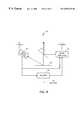
- FIG. 1illustrates an overview of the properties of glyph marks and codes embodied in the glyph marks
- FIG. 2illustrates an embodiment of an image combining graphics and glyphs consistent with the present invention
- FIG. 3illustrates an enlarged view of a portion of the image illustrated in FIG. 2;
- FIG. 4illustrates an image of a pictorial comprising glyphtones consistent with the principles of the present invention
- FIG. 5illustrates an example of a portion of a glyph address carpet code with overlay tiled label code
- FIG. 6illustrates a system for reading an image having embedded data, decoding the embedded data in the image, and developing human-sensible information based on the decoded embedded data
- FIG. 7illustrates a logical configuration of elements consistent with principles of the present invention
- FIG. 8illustrates another embodiment of a system consistent with the principles of the invention
- FIG. 9is another embodiment of a system built in accordance with the principles of the present invention.
- FIG. 10is a diagram illustrating registration of information consistent with the principles of the invention.
- FIG. 11is a block diagram illustrating one embodiment of a lens apparatus consistent with the principles of the invention.
- FIG. 12is a cutaway side view of the lens apparatus shown in FIG. 11;
- FIG. 13illustrates an example of a substrate, an overlay image, and the substrate overlaid with the overlay image as seen through the lens viewport illustrated in FIG. 11 and FIG. 12;
- FIG. 14illustrates another example of a substrate, an overlay image, and the substrate overlaid with the overlay image as seen through the lens viewport illustrated in FIG. 11 and FIG. 12;
- FIG. 15is a flowchart showing the processing performed by computer 400 to register an image
- FIG. 16graphically illustrates the process of creating an image of superimposed neighborhood images in a glyph lattice image, in accordance with the flowchart of FIG. 17;
- FIG. 17is a flowchart showing the processing performed by a computer to determine a quadrant offset angle using a lattice image
- FIG. 18is a flowchart showing the processing performed by a computer to create a composite lattice image for use in determining a quadrant offset angle using a composite lattice image;
- FIG. 19illustrates finding a glyph centroid
- FIG. 20 and FIG. 21illustrate analyzing the composite image, as illustrated in FIG. 16, to accurately determine the rotation angle of the composite image
- FIG. 22illustrates an embodiment of address codes encoded in a portion of a glyph address carpet
- FIG. 23 and FIG. 24form a flow chart showing the disambiguation and address decoding processes performed by a computer
- FIG. 25illustrates a binary data matrix formed from a glyph lattice
- FIG. 26is a flowchart showing an embodiment of correlation steps of FIG. 24;
- FIG. 27illustrates why the correlations determine which way the codes in every other row are shifting
- FIG. 28shows a method for expedited processing when successive captures are processed from an image capture device
- FIG. 29is a block diagram of a user interface image capture system that may be used to capture a user-selected portion of a graphical user interface
- FIG. 30is a block diagram illustrating another embodiment of an image registration system consistent with the principles of the invention.
- FIG. 31is a block diagram showing a cutaway side view of the camera mouse.
- FIG. 1illustrates glyph marks and codes embodied in the glyph marks.
- Glyph marksare typically implemented as a fine pattern on a substrate, such as glyph marks 21 on substrate 24 . Glyph marks are not easily resolved by the unaided human eye. Thus, glyph marks typically appear to the unaided eye as having a uniform gray scale appearance or texture, as illustrated by glyph marks 21 in FIG. 1 .
- Enlarged area 23shows an area of glyph marks 21 .
- Glyph marks 21are comprised of elongated slash-like marks, such as glyph 22 , and are typically distributed evenly widthwise and lengthwise on a lattice of glyph center points to form a rectangular pattern of glyphs. Glyphs are usually tilted backward or forward, representing the binary values of “0” or “1,” respectively. For example, glyphs may be tilted at +45° or ⁇ 45° with respect to the longitudinal dimension of substrate 24 . Using these binary properties, the glyph marks can be used to create a series of glyph marks representing 0's and 1's embodying a particular coding system.
- the glyph marks of enlarged area 23can be read by an image capture device.
- the captured image of glyph markscan then be decoded into 0's and 1's by a decoding device.
- Decoding the glyphs into 0's and 1'screates a glyph code pattern 25 .
- the 0's and 1's of glyph code pattern 25can be further decoded in accordance with the particular coding system used to create glyph marks 21 . Additional processing might be necessary in the decoding stage to resolve ambiguities created by distorted or erased glyphs.
- Glyph markscan be implemented in many ways. Apparatus and methods consistent with the invention read and decode various types of glyph code implementations. For example, glyphs can be combined with graphics or may be used as halftones for creating images.
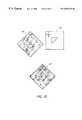
- FIG. 2illustrates an embodiment of an image 210 combining graphics and glyphs consistent with the present invention.
- the graphicscomprise user interface icons.
- Each iconcomprises a graphic overlaid on glyphs.
- the glyphsform an address carpet.
- the glyph address carpetestablishes a unique address space of positions and orientations for the image by appropriate coding of the glyph values.
- FIG. 3illustrates an enlarged view of a portion of image 210 illustrated in FIG. 2 . More particularly, portion 212 illustrates the Lab.avi icon overlaying a portion of the address carpet, which unambiguously identifies the icon location and orientation.
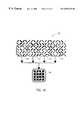
- FIG. 4illustrates an image of a pictorial comprising glyphtones consistent with the present invention.
- Glyphtonesare halftone cells having area-modulated glyphs that can be used to create halftone images incorporating a glyph code.
- FIG. 5illustrates an example of a portion of a glyph address carpet code with overlay tiled label code.
- the u and v glyph address codescomprise the address carpet, and the d codes comprise the overlay tiled label code.
- rows of u address codesare interleaved with rows of v codes.
- Each row of u address codesis offset by two positions so that a diagonal line running down and to the right at 45° cuts across identical u codes in every other row.
- each row of v address codesis offset by two positions so that a diagonal line running down and to the left at 45° cuts across identical v codes in every other row. This property of the u and v address codes allows determination of the precise location within the code from a captured image of glyphs.
- Every sixth column of the address carpetis substituted by d codes, which comprise a label code.
- a label codemay represent additional information, such as a page number of context.
- the label code in FIG. 5is a four-bit label code, comprising bits d 01 , d 02 , d 03 , and d 04 .
- the d codesrepeat throughout the address carpet.
- the d codessubstitute for u and v codes. For example, in the top row, v 13 , v 19 , v 25 , and v 31 are substituted for d 03 , d 04 , d 01 , and d 02 , respectively. In each row, the u and v codes in every sixth column are over written by corresponding d codes.
- the d codescan be decoded to provide a label providing information.
- the d codescould represent, for example, a page number or context information.
- the proper logical identity of the code elementsi.e., addressing is provided by the address code.
- orientation, location, and a labelcan be determined.
- the u and v address codescan be used to determine position, as will be explained in greater detail below, and the d codes provide label information.
- Apparatus and methods consistent with the inventionread embedded data from a substrate, decode the embedded data to determine registration of the substrate relative to a reference in an apparatus, and develop and present human-sensible information based on the registration information.
- the human-sensible informationis visual information registered with the substrate.
- the human-sensible informationmay also comprise, for example, tactile, audible, or other sensory information.
- FIG. 6illustrates a system for reading an image having embedded data, decoding the embedded data in the image, and developing human-sensible information based on the decoded embedded data. More particularly, image capture 470 reads substrate 468 to capture an image having embedded data, decoder 472 decodes the embedded data in the captured image, and information generator 474 develops human-sensible information based on the decoded embedded data, and outputs the information to information output 476 , which represents one or more information output devices.
- the human-sensible informationmay be visual information registered with substrate 468 , and additionally or alternatively may comprise other human-sensible information, such as tactile, audible, or other human-sensible information.
- FIG. 7is a block diagram illustrating a logical configuration of elements in accordance with principles consistent with the invention.
- An image capture device 70captures an image from a substrate 68 .
- Substrate 68has embedded data, such as glyphs embodied thereon.
- Image capture device 70transfers the captured substrate image to a decoder 72 and an image generator 74 .
- the embedded data on substrate 68comprises an address carpet and tiled label code.
- Decoder 72analyzes the embedded data in the captured substrate image to determine information regarding the registration of the substrate, such as orientation, location, and label information. These results are transferred to image generator 74 for further processing.
- Image generator 74processes the results from decoder 72 and the captured substrate image from image capture device 70 .
- image generator 74receives a context code, a location code, and a rotation code from decoder 72 .
- the context codedefines a particular context of substrate 68 , such as a substrate page number.
- the location codedefines the location on substrate 68 where the captured image was taken from.
- the rotationgives the orientation of the substrate relative to the image capture device.
- image generator 74accesses information related to the context code and location code.
- image generator 74retrieves corresponding information and generates an image registered to the substrate.
- the rotation codeenables registering the orientation of the generated image.
- the retrieved informationincludes two types of information: image information in the form of a bit map image representation of substrate page iv, and icon information defining the locations and meaning of icons on substrate page iv.
- image informationin the form of a bit map image representation of substrate page iv
- icon informationdefining the locations and meaning of icons on substrate page iv.
- the size of the retrieved informationmay vary.
- image generator 74retrieves an image of substrate 68 that is the same size as the footprint of display 76 and corresponds to the area of substrate 68 directly under the footprint of display 76 . Because display 76 is aligned with substrate 68 , observer 78 looking at display 76 is given the illusion of looking directly onto substrate 68 . Image generator 74 may also add information to the image, or alter the retrieved image before sending it to display 76 .
- the image sent to display 76may be generated by image generator 74 in many ways.
- image generator 74may merely pass on the image captured by image capture 70 , or a representation of the image captured by image capture 70 .
- a bitmap representation of the entire substrate 68could be stored locally in image generator 74 or on a remote device, such as a device on a network.
- image generator 74retrieves an area corresponding to the codes from the bitmap representation, and forwards the area representation to display 76 for display to a user.
- the area representation retrieved by image generator 74may be the same size as the image captured by image capture 70 , or may be an extended view, including not only a representation of the captured area, but also a representation of an area outside the captured area.
- the extended view approachonly requires image capture 70 to be as large as is necessary to capture an image from substrate 68 that is large enough for the codes to be derived, yet still provides a perception to the user of seeing a larger area.
- FIG. 8is a block diagram illustrating an embodiment of a system consistent with the principles of the invention.
- a substrate 89 having embedded data thereonis positioned below a semitransparent mirror 82 .
- An image from substrate 89is captured by an image capture device 80 .
- Image capture device 80sends the captured image to a decoder 88 , which decodes the image and determines codes from the captured image.
- Decoder 88sends the codes to an image generator 84 .
- Image generator 84processes the codes, creates and/or retrieves image information based on the codes, and sends the image information to semitransparent mirror 82 .
- An observer 86 looking down onto semitransparent mirror 82sees the image generated by image generator 84 overlaid on the image from substrate 89 .
- the overlaid informationcan be dynamically updated and registered with information on substrate 89 based on the decoded image captured by image capture device 80 .
- image capture 80receives the substrate image reflected from semitransparent mirror 82 .
- FIG. 9is another embodiment of a system built in accordance with the principles of the present invention.
- An image from substrate 98is reflected off semitransparent mirror 96 onto projection surface 102 .
- the image from substrate 98is also captured by an image capture device 90 .
- Image capture device 90transfers the image to a decoder 92 , which processes the image to decode registration information and to determine whether further information should be generated. Based on the determination, decoder 92 passes signals to image generator 94 , directing image generator 94 to generate an image.
- Image generator 94generates an image, which is projected onto projection surface 102 .
- Observer 100 viewing projection surface 102sees the image from substrate 98 overlaid and registered with the image generated by image generator 94 .
- the systemmay also include illumination source 104 for illuminating substrate 98 .
- the elementsmay send information to and receive information from network devices. This allows the elements to interact with devices on a network. For example, programs and data may be sent to the elements from network devices, and the devices may send information to the devices on networks.
- FIG. 10is a diagram illustrating registration of information consistent with the principles of the invention. The process may be carried out by the apparatus discussed above.
- Substrate 364has embedded code embodied thereon, and may have images, such as a triangle.
- the embedded codeembodies a code system from which x,y positions on substrate 364 can be determined.
- An image capture devicecaptures a portion of substrate 364 , to thereby capture an image of a portion of the embedded code embodied thereon.
- the embedded codeis decoded to determine an x,y location within the embedded code, and the orientation of substrate 364 , represented by the crosshair arrow on substrate 364 .
- a label codemay also be decoded from the captured embedded code.
- image information 366is retrieved from storage.
- the x,y location information and orientation information decoded from the embedded code embodied on substrate 364are then used to register image information 366 with substrate 364 . These may be used to form a composite image 368 .
- FIG. 11is a block diagram illustrating an embodiment of a lens apparatus consistent with the principles of the invention.
- Lens apparatus 328is comprised of lens viewport 334 , which is supported by support arm 330 .
- a viewer looking down through lens viewport 334observes substrate 332 , which has embedded code embodied thereon.
- a camera(not shown) captures an image of substrate 332 .
- the imageis sent to a computer (not shown), which decodes the x,y location of substrate 332 appearing under lens viewport 334 , the orientation of substrate 332 under lens viewport 334 , and the label code, if any, in the embedded code on substrate 332 .
- the computerBased on the label, x,y location and orientation of substrate 332 , the computer generates overlay image information which is displayed in lens viewport 334 in such a way that the generated image information is registered with substrate 332 .
- the registered overlay imageis projected by an image generator (not shown).
- FIG. 12is a cutaway side view of the lens apparatus shown in FIG. 11 .
- Lens apparatus 328further comprises camera 392 , display 394 , lamp 396 , display controller 398 , computer 400 and semitransparent mirror 402 .
- Lamp 396illuminates substrate 332 (not shown).
- Camera 392which corresponds to image capture devices 70 , 80 , 90 illustrated in FIG. 7, FIG. 8, and FIG. 9, respectively, captures an image of the substrate, and transmits the image to computer 400 .
- Computer 400performs the function of decoders 72 , 82 , 92 illustrated in FIG. 7, FIG. 8, and FIG. 9, respectively.
- Computer 400in combination with display controller 398 and display 394 , performs a function most similar to image generator 84 illustrated in FIG. 8 because the generated image is reflected off semitransparent mirror 402 .
- Computer 400decodes the embedded data in the captured image to determine the x,y location of the captured image, which represents the location of the area on substrate appearing under lens viewport 334 .
- Computer 400also decodes the embedded data in the captured image to determine the orientation of substrate 332 under lens viewport 334 , and the label code, if any, in the embedded code of the captured image. From this information, computer 400 generates the overlay image information, which is sent to display controller 398 . Display controller 398 sends the overlay image information to display 394 . Display 394 generates an overlay image based on the overlay image information from display controller 398 . Observer 390 looking through viewport 334 sees substrate 332 through semitransparent mirror 402 overlaid with the overlay image information generated by image generator 394 .
- FIG. 13illustrates an example of a substrate, an overlay image, and the substrate overlaid with the overlay image as seen through the lens viewport illustrated in FIG. 11 and FIG. 12 .
- the substrate 480is comprised of images of North and South America and embedded data. In one embodiment, the substrate is covered entirely with embedded data.
- a userplaces substrate 480 under lens viewport 334 and camera 392 captures the image appearing under lens viewport 334 and transmits the image to computer 400 .
- Computer 400decodes the embedded data in the captured image from substrate 480 to determine the x,y location of the captured image, which represents the location of the area on substrate appearing under lens viewport 334 .
- Computer 400also decodes the embedded data in the captured image to determine the orientation of substrate 480 under lens viewport 334 , and the label code, if any, in the embedded code of the captured image.
- computer 400From this information, computer 400 generates overlay image information 482 , which is sent to display controller 398 .
- Display controller 398sends overlay image information 482 to display 394 .
- Display 394generates overlay image information 482 , which is reflected off semitransparent mirror 402 through lens viewport 334 .
- Observer 390 looking through viewport 334sees substrate 332 through semitransparent mirror 402 overlaid with overlay image information 482 generated by image generator 394 .
- the usersees borders overlaid on North America.
- FIG. 14illustrates another example of a substrate, an overlay image, and the substrate overlaid with the overlay image as seen through the lens viewport illustrated in FIG. 11 and FIG. 12 . More particularly, FIG. 14 illustrates how the system responds when the user moves substrate 430 under lens viewport 334 .
- substrate 430comprises the lowercase letters “e1” and “world.”
- Substrate 430also includes embedded data embodied thereon (not shown).
- camera 400captures an image of the substrate area under lens viewport 334 .
- Computer 400decodes the embedded data in the captured image from substrate 430 to determine the x,y location of the captured image, which represents the location of the area on substrate appearing under lens viewport 334 . Computer 400 also decodes the embedded data in the captured image to determine the orientation of substrate 430 under lens viewport 334 , and the label code, if any, in the embedded code of the captured image.
- computer 400From this information, computer 400 generates overlay image information “H1,” which is sent to display controller 398 and reflected off semitransparent mirror 402 .
- a user looking through lens viewport 334sees the “e” overlaid with overlay image information “H1,” as illustrated in the upper right of 14 .
- camera 392captures an image of the new area under lens viewport 334 .
- Computer 400decodes the embedded data in the new area, and generates an image of “o,” which is sent to display controller 398 .
- a user looking through lens viewport 334sees the “1” overlaid with overlay image information “o,” as illustrated in the lower right of 14 .
- the overlay image informationis dynamically modified to appear in lens viewport 334 . More particularly, the overlay image information is dynamically modified to maintain registration with the area of substrate 430 appearing under lens viewport 334 .
- Registering the overlay image with the substraterequires a precise determination of the orientation of the substrate with respect to the image capture device.
- computer 400resolves the angle between 0° and 360°. This is done in two steps. First, the quadrant offset angle (between ⁇ 45° and +45°) from the lattice axis to the nearest quadrant axis is determined. Second, the quadrant angle of 0°, 90°, 180° or 270° is determined. The sum of the quadrant offset angle and the quadrant angle is the orientation angle.
- FIG. 15is a flowchart showing the processing performed by computer 400 to register an image.
- Computer 400first captures an image of the substrate, including a lattice of glyphs (step 130 ), and then determines the quadrant offset angle of the lattice of glyphs between ⁇ 45° and +45° relative to the image capture device (step 132 ).
- Computer 400then decodes the glyphs in the image into data composed of 0's and 1's (step 134 ). From the decoded data, computer 400 determines the quadrant angle of 0°, 90°, 180°, or 270°, and then correlates the data from step 134 with the address carpet code used to create the address carpet to determine the x,y location of the captured image (step 136 ).
- Computer 400sums the quadrant offset angle and the quadrant angle to determine the orientation angle between the lattice code and the image capture device.
- Computer 400also determines a context code from the decoded data (step 138 ). Using the context code, computer 400 generates a context-specific overlay (step 140 ), and applies a context-specific x,y, scale and rotation offset values to the overlay (step 142 ). Finally, computer 400 applies the calculated x,y and rotation values to the overlay (step 144 ), and generates image information for display of the image (step 146 ).
- the glyphsdo not include a context label.
- step 138is not performed and retrieval of image information is based only on location code.
- FIG. 16illustrates graphically the process of creating an image of superimposed neighborhood images in a glyph lattice image, in accordance with the flowchart of FIG. 17 . More particularly, in the embodiment shown in FIG. 16, representative neighborhood images 204 , 206 , 208 , and 210 of glyph lattice image 200 are superimposed to form the composite image 202 of superimposed neighborhood images. From composite image 202 , a quadrant angle can be determined, as discussed in detail below.
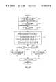
- FIG. 17is a flowchart showing the processing performed by computer 400 to create a composite lattice image for use in determining the quadrant offset angle.
- Computer 400first selects a seed pixel from the image captured by camera 392 (step 162 ). In one embodiment, the selection of seed pixels begins at captured image coordinate 0 , 0 .
- Computer 400finds a local minimum in the vicinity of the seed pixel, indicating the presence of a glyph (step 164 ). Computer 400 then finds the centroid of this glyph (step 166 ), and determines whether the glyph has sufficient contrast with its immediate surround to be reliably decoded (step 168 ). Glyph centroids are discussed in greater detail with respect to FIG. 19 .
- Computer 400determines whether there have already been too many sampling attempts (step 174 ). If too many sampling attempts, the process fails (step 172 ). If not too many, processing continues at step 162 by selecting the next seed pixel for analysis at a particular x and y interval from the previously analyzed seed pixel (step 162 ). The particular x and y interval is based on the height and width of the composite image.
- step 168computer 400 , using the glyph centroid as the origin, adds a subsample of size w ⁇ h of the captured image to the composite image (step 176 ). Computer 400 then determines whether enough samples have been taken (step 178 ). If the limit is not exceeded, computer 400 determines whether there have been too many sampling attempts (step 170 ).
- computer 400divides the values of the composite image by the number of successful samples to determine an average of the values of pixels in the subsample regions (step 180 ). From the resulting composite image, computer 400 determines the quadrant offset angle (step 182 ). One way to determine the quadrant offset angle is illustrated in FIG. 18 . The preciseness of the quadrant angle is proportional to the size of the composite image. Put another way, a large composite image will provide a more precise quadrant angle than a small composite image.
- FIG. 18is a flowchart showing the processing performed by computer 400 to determine a quadrant offset angle using a composite lattice image generated in accordance with the flowchart of FIG. 17 .
- Computer 400first finds the darkest pixel along an arc between zero and 90 degrees at a distance from the origin equal to the glyph pitch, the distance between adjacent glyphs on the lattice of glyphs (step 230 ), and then finds the centroid of the shape containing this pixel (step 232 ). Once the centroid is found, computer 400 assumes that the lattice axis passes through this centroid and the origin, so it then estimates the approximate location of the next minimum along the lattice axis based on the centroid position and the glyph pitch (step 234 ).
- computer 400finds the local minimum around the estimated location (step 236 ), and finds the centroid of the shape containing that minimum (step 238 ). Based on the size of the composite image, computer 400 determines whether the last possible minimum along the lattice axis has been found (step 240 ). If the last possible minimum has not been found, processing continues at step 234 . If the last possible minimum has been found, computer 400 fits a straight line, referred to as the axis line, from the origin through the centroids (step 242 ). Computer 400 then determines the angle of the axis line, between 0° and 90° (step 244 ), and this angle is then offset to fall between ⁇ 45 degrees and +45 degrees by subtracting 45° (step 246 ).
- FIG. 19illustrates graphically one way to find a glyph centroid consistent with the principles of the invention.
- Centroidsare used in the present invention in two ways: to align the subimages, and in the case of angle finding the centroid is used to more accurately establish the axis of the lattice, thus providing the angle.
- FIG. 20 and FIG. 21illustrate the process of analyzing the composite image, as illustrated in FIG. 16, to accurately determine the rotation angle of the composite image.
- the quadrant offset angle of the composite imagerepresents an accurate determination of the orientation of the glyph lattice in the original captured image, subject to determination of the proper angular quadrant. Combining the quadrant offset angle and the angular quadrant provides a complete determination of the relative angle of the image capture device and the substrate.
- FIG. 20illustrates one example where the quadrant offset angle is 0°
- FIG. 21illustrates another example where the quadrant offset angle is the finite angle theta.
- Apparatus and methods consistent with the inventionuse address carpet codes and associated processes similar to those shown in U.S. Pat. No. 6,327,395, entitled GLYPH ADDRESS CARPET METHODS AND APPARATUS FOR PROVIDING LOCATION INFORMATION IN A MULTIDIMENSIONAL ADDRESS SPACE, issued Dec. 4, 2001, which is hereby incorporated by reference.
- FIG. 22illustrates an embodiment of the address codes encoded in a portion of a glyph address carpet similar to the u and v codes described above.
- the addressesare encoded by alternating rows of “A” address code sequences and “B” address code sequences.
- the position along each sequence in each rowshould be unambiguously determinable from a predetermined length subsequence. For example, an N-bit shift register maximal length code can be uniquely determined in position from an N-bit subsequence.
- Each address code sequenceis a fifteen bit sequence, with the A sequence indexed running left to right, and the B sequence indexed running in a reverse direction, right to left.
- Each row of A code sequencesis offset by two glyph positions relative to the previous and next row of A addresses.
- each row of B code sequencesis offset in the opposite direction by two positions.
- the encoding schemehas two key characteristics: parallel rows including two sets of one-dimensional unique address codes and relative offsets among members of the two sets so that the offset between each pair from the two sets is unique. This establishes two-dimensional unique address locations.
- Computer 400decodes address information encoded in the glyphs by analyzing the captured image area in two steps.
- image capture devices 70 , 80 , 90 , and 392capture an area of a substrate that is angularly aligned as shown in the pattern of bits shown in 22 .
- the substrate and image capture devicemay not be aligned to one another.
- the relative angle between the twocould be oriented anywhere from 0° to 360°. Therefore, computer 400 must first determine the orientation of the image as part of decoding and interpreting the address information.
- the orientation of the imageis determined by analyzing the captured image. This process is called disambiguation.
- disambiguationOne method of disambiguation is described in U.S. Pat. No. 5,521,372 to Hecht et al. expressly incorporated herein by reference.
- computer 400After determining the proper orientation of the image, computer 400 decodes the address of the selected location in the address carpet. Disambiguation and address decoding processes performed by computer 400 and consistent with the present invention will now be described in greater detail.
- FIG. 23 and FIG. 24form a flow chart showing exemplary disambiguation and address decoding processes performed by computer 400 on the captured image area.
- Computer 400begins the disambiguation process by image processing the captured portion of the address carpet to find a glyph seed.
- a glyph seedis a first-identified glyph having readable glyphs around it. Once a glyph seed has been found, the glyph lattice can be determined by processing neighbors of the glyph seed. The glyphs are then decoded as 1's or 0's, which are filled into a binary data matrix having rows and columns corresponding to the glyph lattice rows. The orientation may still be ambiguous with respect to 901 and 1801 rotations.
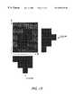
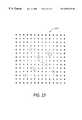
- FIG. 25illustrates a binary data matrix (BDM) 2310 formed from a glyph lattice captured by the image capture device. Locations in the BDM correspond to locations in the glyph lattice, and thus the size of the BDM corresponds closely to the size of the glyph lattice.
- BDMbinary data matrix
- Each location of the glyph latticeis analyzed to determine which value should be placed in the corresponding location of the BDM.
- the BDMis filled with a value, for example ⁇ , which indicates that no attempt has been made to read the glyph.
- ⁇is replaced by a value indicating the result of the glyph analysis.
- a Bindicates a border location
- an Xindicates that no interpretable glyph was found at the corresponding location of the glyph lattice
- an Eindicates a glyph at the edge of the captured image portion
- a 0indicates a back slash glyph
- a 1indicates a forward slash glyph
- dindicates a label code.
- the area of the matrix corresponding to the captured imageis filled with 0's and 1's
- the edgeis bounded by E's
- the X'scorrespond to locations that have no readable glyphs.
- the image capture devicemight be oriented relative to the substrate at any angle. Therefore, the captured image could be oriented at any angle.
- a BDM of 0's and 1'sis derived from the captured image, it is uncertain whether the BDM is oriented at 0° (i.e., correctly oriented), 90°, 180°, or 270° relative to the original code pattern in the glyph address carpet from which the image was captured.
- the orientationcould be provided by auxiliary information such as physical system constraints. However, the orientation can be uniquely determined directly from the address codes.
- a reference glyph locationis selected (step 2211 ). This location may be chosen in a variety of ways, but is typically a location which represents the selection. For example, the reference glyph location could be at the center of the BDM.
- BDM 1The original BDM developed from the captured image is referred to as BDM 1 .
- Computer 400makes a copy of BDM 1 and rotates the copy clockwise 90° to form a second binary data matrix, BDM 2 (step 2214 ).
- BDM 2By rotating BDM 1 by 90°, the rows of BDM 1 become the columns of BDM 2 , and the columns of BDM 1 become the rows of BDM 2 .
- all bit values in BDM 2are flipped from 0 to 1, and 1 to 0, because a 45° slash glyph rotated 90° appears as the opposite state of the non-rotated glyph.
- Computer 400then performs a correlation separately on the odd and even rows of BDM 1 (step 2216 ) to determine whether code in the rows are staggered forward or backward.
- the correlationis also performed for the odd and even rows of BDM 2 (step 2218 ).
- the correlationis performed over all the rows of each BDM, and results in correlation value C 1 for BDM 1 and correlation value C 2 for BDM 2 .
- FIG. 26is a flowchart showing an embodiment of correlation steps 2216 and 2218 of FIG. 23 .
- the processdetermines a correlation value for every other line of a BDM along diagonals in each direction, and sums the row correlation values to form a final correlation value for the odd or even rows.
- the processis performed on the odd rows of BDM 1 to form correlation value C 1 ODD for BDM 1 , the even rows of BDM 1 to form correlation value C 1 EVEN for BDM 1 , the odd rows of BDM 2 to form correlation value C 2 ODD for BDM 2 , the even rows of BDM 2 to form correlation value C 2 EVEN for BDM 2 .
- the BDM that is oriented at 01 or 1801will have a larger C ODD +C EVEN than the other BDM.
- Computer 400first inputs the BDM (step 2410 ), and then copies every other row to a temporary matrix (step 2412 ). Identical processes are then performed for diagonals to the right and to the left. Steps 2414 , 2416 , 2418 , 2420 , 2422 and 2424 process the diagonals to the right. For example, in FIG. 27 the steps correlate along the diagonals moving from the upper left to lower right. First, row count N and correlation value C_RIGHT are each initialized to zero (step 2414 ). Row N is shifted two places to the right, and correlated with the next row (step 2416 ). C_N is then set to this value (step 2418 ).
- the steps on the right of FIG. 26are similar to steps 2414 , 2416 , 2418 , 2420 , 2422 and 2424 , but process diagonals running from the upper right to lower left to develop correlation value C_LEFT. After correlating the right and left diagonals to determine C_RIGHT and C_LEFT, a final correlation value C is determined by subtracting C_LEFT from C_RIGHT. For example, if odd rows for BDM 1 are processed, the C value becomes C 1 ODD for BDM 1 .
- the process steps of FIG. 26are performed for the odd and even rows of BDM 1 and the odd and even rows of BDM 2 . From this information, the correlation value C 1 for BDM 1 is set to C 1 EVEN +C 1 ODD (as determined by FIG. 26 for the rows of BDM 1 ), and the correlation value C 2 for BDM 2 is set to C 2 EVEN +C 2 ODD (as determined by FIG. 26 for the rows of BDM 1 ).
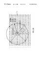
- FIG. 27illustrates why the correlations determine which way the codes in every other row are shifting.
- the codes along the diagonal starting at A 1 in the first position of the second rowshould have the same value in every other row along the diagonal, except for erasures and errors.
- the codes along the diagonal starting at B 1 in the upper right cornershould have the same value in every other row along the diagonal, except for erasures or errors. This is true for each value along the diagonal in the odd rows running respectively from B 2 , B 3 , . . . B 15 in the top row.
- the strong correlations along the diagonals running down and to the left on the odd rowsand the strong correlations along the diagonals running down and to the right on the even rows indicate that the codes in the even rows are shifting to the right, and the codes in the odd rows are shifting to the left.
- each BDMtherefore, four correlation values are developed: 1) odd rows, right to left, 2) odd rows, left to right, 3) even rows, right to left and 4) even rows, left to right.
- the strongest correlation value for the even rows, and strongest correlation value for the odd rowsis chosen, and these become C EVEN and C ODD for that BDM (steps 2216 and 2218 ).
- C EVEN and C ODDare then added to form a final C correlation value for that BDM.
- the BDM with the strongest correlation valueis the BDM that is oriented at either 0° or 180° because of the relative orientation of the codes in the odd and even rows.
- step 2230is performed to determine which direction the code in each line runs (as opposed to which way the code is staggered).
- the codes in the odd linesare staggered in one direction, and the codes in the even lines are staggered in the other. This staggering property of the code, in conjunction with knowing the respective codes that run in the odd lines and even lines, allows determination of the proper 0° orientation of the BDM.
- C 1is greater than C 2 (step 2220 )
- BDM 1is selected for further processing.
- C 1 being greater than C 2indicates that the one-dimensional codes of BDM 1 are most strongly correlated and are, therefore, oriented at either 0° or 180° (step 2222 ).
- C 2is greater than C 1
- BDM 2is selected for further processing, because the higher correlation indicates that BDM 2 is oriented at either 0° or 180° (step 2224 ).
- computer 400Before determining the address location of the captured image, however, computer 400 must first determine whether the selected BDM is at 0° (i.e., oriented correctly), or rotated by 180°.
- FIG. 24is a flowchart showing the steps of how computer 400 determines the address of the captured area of the glyph carpet.
- bit positions along a diagonal in the BDMwhen the BDM is oriented at 0°, have the same value at every other row.
- the image capture process and interference from the visual indicia and substitution label codes d(as shown in FIG. 25 ), however, may result in errors and erasures in the BDM data.
- computer 400performs a majority vote along each diagonal of the odd rows in the direction the odd rows are staggered, and repeats the majority vote process for even rows along the each diagonal in the direction the even rows are staggered (step 2225 ).
- first and second code sequencesshould match a subsequence of the original pseudo noise address sequence respectively corresponding to the odd or even set of rows.
- Computer 400then retrieves the original pseudo noise address code (Get Code 1 ) for rows staggered forward (step 2226 ), and retrieves the original pseudo noise address code for (Get Code 2 ) for rows staggered backward (step 2228 ). Using the original pseudo noise address code for each code set A and B, and the code from the majority voting, computer 400 performs four cross correlations (step 2230 ) to establishes the best match of the glyph sequence with the PN sequence location for the odd and even rows.
- two adjacent rows of the BDM closest to the reference element chosen in step 2211are correlated with the respective complete PN sequences that created the original address carpet.
- the PN sequencescould be identical.
- a forward and backward correlationis performed for each row.
- the four correlationsdevelop four pairs of peak correlation and position values:
- U 1 and V 1are used to calculate the X, Y position of the reference glyph location chosen in step 2211 (step 2236 ).
- U 2 and V 2are used to calculate the X, Y position of the reference glyph location chosen in step 2211 (step 2234 ).
- the address informationis determined in accordance with the following equations:
- the calculated X, Y positionis then returned (step 2238 ). Note that diagonals correspond to constant values of U and V, respectively, while rows and columns correspond to constant X and Y. Note also that U and V could be used directly as address parameters.
- an X, Y value associated with the reference point chosen in step 2211has been determined.
- computer 400associates the X, Y coordinates with a logical reference, or a combination of a logical reference and a control signal (e.g., a button click), with a particular operation to be performed.
- the X, Y coordinatescould be used as an index into a table of operations performable by computer 400 or other device under direction of computer 400 .
- the X, Y coordinatescould be associated with a file open command that opens a file associated with an icon located near the X, Y coordinates in the address space.
- Virtually any operation that can be performed by computer 400could be associated with a particular X, Y coordinate, or range of X, Y coordinates.
- FIG. 28shows a method for expedited processing when successive image captures are processed from an image capture device when there is relative motion between the image capture device and the substrate at a velocity less than or equal to a predetermined value V.
- a first imageis captured, and the entire address space is searched in accordance with the teachings above to determine the location coordinates of location # 1 .
- location # 1has coordinates u 16 , v 22 .
- the index range used in searching for a correlation maximum indicating location # 2can be limited to the index range u i ,v j of locations within the circle of radius R around the coordinates of location # 1 . If a suitable correlation peak is not found, processing returns to searching the entire address space. Not finding a suitable correlation peak might indicate that motion has jumped outside the circle or the substrate has been changed.
- the methodexpedites processing of information extraction and can enable applications such as real-time frame-to-frame image capture. This can be used for smoothed motion display and for gesture motion capture.
- FIG. 29is a block diagram of a user interface image capture system that may be used to capture a user-selected portion of a graphical user interface, such as glyph address carpet 1732 , and decode the glyphs in the captured portion.
- computer system 1712is a general purpose computer system, such as a conventional personal computer or laptop computer, that includes main memory 1716 , read only memory (ROM) 1718 , storage device 1720 , processor 1722 , and communication interface 1724 , all interconnected by bus 1726 .
- Bus 1726also connects to registered image system 1754 , cursor control 1714 , and frame capture 1728 .
- Registered image system 1754may be comprised of a system embodying principles as shown and described with respect to FIG. 7, FIG. 8, FIG. 9, and FIG. 12, or other registered image system consistent with the principles of the invention.
- registration system 328 of FIG. 12may be implemented with the system of FIG. 29 by using computer system 1712 as computer 400 in FIG. 12 .
- Frame capture 1728receives a captured image from registered image system 1754 and provides the captured image to processor 1722 .
- Processor 1722decodes embedded data in the image to determine information, such as x,y location, label, and orientation information as described above, and sends image information based on the decoded information to registered image system 1754 .
- Registered image system 1754generates an image registered with the substrate based on the image information from processor 1722 .
- Registered image system 1754may receive information from the other devices illustrated in FIG. 29, and may transmit information to the devices. This allows other devices, for example on a network, to interact with registered image system 1754 .
- Camera pen 1710 and mouse 1752can provide control signals to processor 1722 in conjunction with the operation of registered image system 1754 .
- user interface substrate 1732may be used as the substrate from which registered image system 1754 captures an image.
- Camera pen 1710is connected to frame capture 1728 and mouse 1752 and acts as an auxiliary pointing device. Camera pen 1710 transmits image information to frame capture 1728 .
- button 1714 of camera pen 1710is wired to mouse 1752 so that when a user presses button 1714 a signal travels through the circuitry of mouse 1752 to cursor control 1714 .
- the signalcauses processor 1722 to run a program that directs frame capture 1728 to capture the image from camera pen 1710 .
- both the image line and signal line from camera pen 1710are input directly into frame capture 1728 .
- the lines between camera pen 1710 and computer 1712can be wired in any way that provides capture of the image from camera pen 1710 .
- the usermakes a selection by placing camera pen 1710 on or near visual indicia on glyph address carpet 1732 , and pressing button 1714 .
- Pressing button 1714causes camera pen 1710 to capture the portion of the address carpet 1732 under the tip of camera pen 1710 , and transmit the image to computer 1712 , via frame capture 1728 , for analysis.
- the button 1714or multiple buttons, can be used for additional signaling, as in a double click, hold down.
- Computer 1712is also connected to local area network (LAN) 1734 for communicating with devices connected to LAN 1734 .
- LAN 1734may be connected to a computer 1740 , a printer 1736 , and a mass storage 1738 .
- LAN 1734may be also connected to a gateway 1742 for connecting to another network 1744 .
- Network 1744may be connected to a computer 1746 , a printer 1748 , and a database 1750 .
- computer 1712can perform operations using the devices connected to these networks. For example, a document selected for printing by camera pen 1710 or mouse 1752 can be printed on printer 1736 or printer 1748 . Similarly, a user may use computer 1712 to request a file on database 1750 .
- main memory 1716is a random access memory (RAM) or a dynamic storage device that stores instructions executed by processor 1722 .
- Main memory 1716may also store information used in executing instructions.
- ROM 1718is used for storing static information and instructions used by processor 1722 .
- Storage device 1720such as a magnetic or optical disk, also stores instructions and data used in the operation of computer system 1712 .
- Display 1730may be a CRT or other type of display device.
- Cursor control 1714controls cursor movement on display 1730 .
- Cursor control 1714may be, for example, a mouse, a trackball or cursor direction keys.
- the system shown in FIG. 29can be used to implement the glyph address carpet capture and translation system described herein.
- the apparatus and methods described hereinmay be implemented by computer system 1712 using hardware, software, or a combination of hardware and software.
- the apparatus and methods described hereinmay be implemented as a program in any one or more of main memory 1716 , ROM 1718 , or storage device 1720 .
- processor 1722executes programs which analyze captured portions of a glyph address carpet to determine address information encoded in the glyphs.
- Such programsmay be read into main memory 1716 from another computer-readable medium, such as storage device 1720 .
- Execution of sequences of instructions contained in main memory 1716causes processor 1722 to perform the process steps consistent with the present invention described herein.
- Execution of sequences of instructions contained in main memory 1716also causes processor to implement apparatus elements that perform the process steps.
- Hard-wired circuitrymay be used in place of or in combination with software instructions to implement the invention. Thus, embodiments of the invention are not limited to any specific combination of hardware circuitry and software.
- Non-volatile memory mediaincludes, for example, optical or magnetic disks, such as storage device 1720 .
- Volatile memory mediaincludes RAM, such as main memory 1716 .
- Transmission mediaincludes coaxial cables, copper wire and fiber optics, including the wires that comprise bus 1726 . Transmission media can also take the form of acoustic or light waves, such as those generated during radiowave and infrared data communications.
- Computer-readable mediainclude, for example, a floppy disk, a flexible disk, hard disk, magnetic tape, or any other magnetic storage medium, a CD-ROM, any other optical medium, punchcards, papertape, any other physical medium with patterns of holes, a RAM, a PROM, an EPROM, a FLASH-EPROM, any other memory chip or cartridge, a carrier wave as described hereinafter, or any other medium from which a computer can read and use.
- Various forms of computer readable mediamay be involved in carrying one or more sequences of instructions to processor 1722 for execution.
- the instructionsmay initially be carried on a magnetic disk or a remote computer.
- the remote computercan load the instructions into its dynamic memory and send the instructions over a telephone line using a modem.
- a modem local to computer system 1712can receive the data on the telephone line and use an infrared transmitter to convert the data to an infrared signal.
- An infrared detectorcoupled to appropriate circuitry can receive the data carried in the infrared signal and place the data on bus 1726 .
- Bus 1726carries the data to main memory 1716 , from which processor 1722 retrieves and executes the instructions.
- the instructions received by main memory 1716may optionally be stored on storage device 1720 either before or after execution by processor 1722 .
- Computer system 1712also includes a communication interface 1724 coupled to bus 1726 .
- Communication interface 1724provides two way communications to other systems.
- communication interface 1724may be an integrated services digital network (ISDN) card or a modem to provide a data communication connection to a corresponding type of telephone line.
- ISDNintegrated services digital network
- Communicationmay also be, for example, a local area network (LAN) card to provide communication to a LAN.
- LANlocal area network
- Communication interface 1724may also be a wireless card for implementing wireless communication between computer system 1712 and wireless systems. In any such implementation, communication interface 1724 sends and receives electrical, electromagnetic or optical signals that carry data streams representing various types of information.
- the link between communication interface 1724 and external devices and systemstypically provides data communication through one or more networks or other devices.
- the linkmay provide a connection to a local network (not shown) to a host computer or to data equipment operated by an Internet Service Provider (ISP).
- ISPInternet Service Provider
- An ISPprovides data communication services through the world wide packet data communications network now commonly referred to as the “Internet.”
- InternetWorld wide packet data communications network now commonly referred to as the “Internet.”
- Local networks and the Internetboth use electrical, electromagnetic or optical signals that carry digital data streams.
- the signals through the various networks and the signals between the networks and communication interface 1724which carry the digital data to and from computer system 1712 , are exemplary forms of carrier waves transporting the information.
- Computer system 1712can send messages and receive data, including program code, through the network(s) via the link between communication interface 1724 and the external systems and devices.
- a servermight transmit a requested code for an application program through the Internet, an ISP, a local network, and communication interface 1724 .
- Program code received over the networkmay be executed by processor 1722 as it is received, and/or stored in memory, such as in storage device 1720 , for later execution. In this manner, computer system 1712 may obtain application code in the form of a carrier wave.
- FIG. 30illustrates another embodiment of an image registration system consistent with the principles of the invention.
- Camera mouse 118is comprised of camera mouse buttons 110 , 112 , 114 , and a signal cable 120 .
- a micro camera (not shown) in camera mouse 118captures the area of substrate 122 defined by the target area indicators in response to the observer activating one or more of camera mouse buttons 110 , 112 , 114 .
- the image captured by the micro cameracan be processed locally in mouse 118 by a processing element (not shown) or sent over signal cable 120 for processing by a processing element in a device attached to camera mouse 118 .
- the embedded data captured in the imagecan be decoded.
- camera mouse 118allows a user to place camera mouse 118 over a particular area of substrate 122 and capture an image of the area of substrate 122 , which is then displayed in display 150 .
- the embedded code in the captured imageis decoded by a processing element to develop decoded information.
- the decoded informationmay represent anything about the substrate, such as context, location, and/or orientation.
- the processing elementanalyzes the decoded information and may perform an operation based on the decoded information and button controls, or queue the codes and button controls in a syntax queue to await further codes and button controls.
- image informationis generated and displayed as an image on display 150 .
- image informationmay comprise the actual image captured by micro camera 134 , a representation of the captured image, the actual image captured in addition to other information related to the captured image, or simply information related to the captured image without the captured image.
- a representation of the substrateis retrieved and combined with the captured image to form a composite image on display 150 that shows the captured image and the extended area surrounding the captured image.
- Display 150shows David's Docum icon, which is the captured image, with superimposed cross hairs. Display 150 also shows an image 250 of David's Docum, indicating that that icon has been selected by the user. For example, if the user places the mouse over David's Docum, the mouse captures the image of David's Docum from substrate 122 , and displays the captured image on display 150 . If the user then activates a mouse button to select the icon, a representation of the David's Docum icon is displayed in display 150 as David's Docum icon 250 .
- FIG. 31is a block diagram showing a cutaway side view of camera mouse 118 .
- Camera mouse 118includes a micro camera 134 , an XY motion sensor 136 , illuminators 152 , and processing element 138 .
- Processing element 138processes signals from XY motion sensor 136 and images from micro camera 134 .
- XY sensor 136may be removed.
- Micro camera 134receives an image of substrate 122 reflected off semitransparent mirror 116 .
- An observer 130 viewing an image on display 150may capture the image by pressing one or more of camera mouse buttons 110 , 112 , or 114 .
- the area of substrate 122 captured by micro camera 134is then processed by processing element 138 .
- FIG. 31illustrates processing element 138 located in mouse 118 , all or part of the processing may be performed externally by processing elements connected to camera mouse 118 by signal cable 120 .
Landscapes
- Engineering & Computer Science (AREA)
- Physics & Mathematics (AREA)
- General Physics & Mathematics (AREA)
- Theoretical Computer Science (AREA)
- Multimedia (AREA)
- Computer Vision & Pattern Recognition (AREA)
- Image Processing (AREA)
Abstract
Description


Claims (13)
Priority Applications (6)
| Application Number | Priority Date | Filing Date | Title |
|---|---|---|---|
| US09/455,304US6678425B1 (en) | 1999-12-06 | 1999-12-06 | Method and apparatus for decoding angular orientation of lattice codes |
| DE60022969TDE60022969T2 (en) | 1999-12-06 | 2000-12-04 | Method and device for registration of spatial information |
| DE60039314TDE60039314D1 (en) | 1999-12-06 | 2000-12-04 | Method and device for registration, presentation and decoding of information for spatial registration |
| EP00310774AEP1107184B1 (en) | 1999-12-06 | 2000-12-04 | Method and apparatus for registering spatial information |
| EP05009155AEP1557793B1 (en) | 1999-12-06 | 2000-12-04 | Method and apparatus for registering, displaying and decoding of information for spatial registration |
| JP2000371332AJP4651184B2 (en) | 1999-12-06 | 2000-12-06 | Method and apparatus for registering, displaying and decoding spatially aligned information |
Applications Claiming Priority (1)
| Application Number | Priority Date | Filing Date | Title |
|---|---|---|---|
| US09/455,304US6678425B1 (en) | 1999-12-06 | 1999-12-06 | Method and apparatus for decoding angular orientation of lattice codes |
Publications (1)
| Publication Number | Publication Date |
|---|---|
| US6678425B1true US6678425B1 (en) | 2004-01-13 |
Family
ID=29780597
Family Applications (1)
| Application Number | Title | Priority Date | Filing Date |
|---|---|---|---|
| US09/455,304Expired - Fee RelatedUS6678425B1 (en) | 1999-12-06 | 1999-12-06 | Method and apparatus for decoding angular orientation of lattice codes |
Country Status (1)
| Country | Link |
|---|---|
| US (1) | US6678425B1 (en) |
Cited By (38)
| Publication number | Priority date | Publication date | Assignee | Title |
|---|---|---|---|---|
| US20020084335A1 (en)* | 2000-03-21 | 2002-07-04 | Petter Ericson | Apparatus and methods relating to image coding |
| US20020170970A1 (en)* | 2001-05-15 | 2002-11-21 | Welch Allyn Data Collection, Inc. | Optical reader having decoding and image capturing functionality |
| US20020171745A1 (en)* | 2001-05-15 | 2002-11-21 | Welch Allyn Data Collection, Inc. | Multimode image capturing and decoding optical reader |
| US20030115470A1 (en)* | 2001-12-14 | 2003-06-19 | Cousins Steve B. | Method and apparatus for embedding encrypted images of signatures and other data on checks |
| US20040003024A1 (en)* | 2002-06-26 | 2004-01-01 | Jarkko Sairanen | Method, system and computer program product for personalizing the functionality of a personal communication device |
| US20040010446A1 (en)* | 2002-07-08 | 2004-01-15 | Marko Vanska | Mobile customer relationship management |
| US20040087273A1 (en)* | 2002-10-31 | 2004-05-06 | Nokia Corporation | Method and system for selecting data items for service requests |
| US20040093274A1 (en)* | 2002-11-08 | 2004-05-13 | Marko Vanska | Method and apparatus for making daily shopping easier |
| US20040155110A1 (en)* | 2001-07-13 | 2004-08-12 | Michael Ehrhart | Optical reader having a color imager |
| US20050125745A1 (en)* | 2003-12-08 | 2005-06-09 | Jyri Engestrom | Apparatus, system, method and computer program product for creating shortcuts to functions in a personal communication device |
| US20050222918A1 (en)* | 2002-11-01 | 2005-10-06 | Marko Vanska | Disposable mini-applications |
| US20060002610A1 (en)* | 2004-07-02 | 2006-01-05 | Hartti Suomela | Initiation of actions with compressed action language representations |
| US20070057060A1 (en)* | 2005-09-14 | 2007-03-15 | Fuij Xerox Co., Ltd | Scanner apparatus and arrangement reproduction method |
| US20070274561A1 (en)* | 1999-05-19 | 2007-11-29 | Rhoads Geoffrey B | Methods and devices employing optical sensors and/or steganography |
| US20090254954A1 (en)* | 2004-11-02 | 2009-10-08 | Yong-Seok Jeong | Method and apparatus for requesting service using multi-dimensional code |
| US20090262569A1 (en)* | 2007-10-17 | 2009-10-22 | Naoharu Shinozaki | Semiconductor memory device with stacked memory cell structure |
| US20100096458A1 (en)* | 1999-10-01 | 2010-04-22 | Anoto Aktiebolag (Anoto Ab) | Product provided with a coding pattern and apparatus and method for reading the pattern |
| US20100295783A1 (en)* | 2009-05-21 | 2010-11-25 | Edge3 Technologies Llc | Gesture recognition systems and related methods |
| US7991153B1 (en) | 2008-08-26 | 2011-08-02 | Nanoglyph, LLC | Glyph encryption system and related methods |
| US20120067954A1 (en)* | 2010-09-16 | 2012-03-22 | Madhav Moganti | Sensors, scanners, and methods for automatically tagging content |
| US20120128539A1 (en)* | 2008-11-05 | 2012-05-24 | Johnson Control Technology Company | Air purification system for vehicles |
| US8391851B2 (en) | 1999-11-03 | 2013-03-05 | Digimarc Corporation | Gestural techniques with wireless mobile phone devices |
| US8396252B2 (en) | 2010-05-20 | 2013-03-12 | Edge 3 Technologies | Systems and related methods for three dimensional gesture recognition in vehicles |
| US8467599B2 (en) | 2010-09-02 | 2013-06-18 | Edge 3 Technologies, Inc. | Method and apparatus for confusion learning |
| US8533192B2 (en) | 2010-09-16 | 2013-09-10 | Alcatel Lucent | Content capture device and methods for automatically tagging content |
| US8582866B2 (en) | 2011-02-10 | 2013-11-12 | Edge 3 Technologies, Inc. | Method and apparatus for disparity computation in stereo images |
| US20130308773A1 (en)* | 2012-05-21 | 2013-11-21 | Video Expressions LLC | Capturing video of an image with embedded code to access content |
| US8655093B2 (en) | 2010-09-02 | 2014-02-18 | Edge 3 Technologies, Inc. | Method and apparatus for performing segmentation of an image |
| US8655881B2 (en) | 2010-09-16 | 2014-02-18 | Alcatel Lucent | Method and apparatus for automatically tagging content |
| US8657200B2 (en) | 2011-06-20 | 2014-02-25 | Metrologic Instruments, Inc. | Indicia reading terminal with color frame processing |
| US8666978B2 (en) | 2010-09-16 | 2014-03-04 | Alcatel Lucent | Method and apparatus for managing content tagging and tagged content |
| US8666144B2 (en) | 2010-09-02 | 2014-03-04 | Edge 3 Technologies, Inc. | Method and apparatus for determining disparity of texture |
| US8705877B1 (en) | 2011-11-11 | 2014-04-22 | Edge 3 Technologies, Inc. | Method and apparatus for fast computational stereo |
| US20140185871A1 (en)* | 2012-12-27 | 2014-07-03 | Sony Corporation | Information processing apparatus, content providing method, and computer program |
| US20140294297A1 (en)* | 2012-11-19 | 2014-10-02 | Nta Enterprise, Inc. | Image processing for forming realistic stratum detritus detail in a camouflage pattern and a camouflage pattern formed thereby |
| US8970589B2 (en) | 2011-02-10 | 2015-03-03 | Edge 3 Technologies, Inc. | Near-touch interaction with a stereo camera grid structured tessellations |
| US10721448B2 (en) | 2013-03-15 | 2020-07-21 | Edge 3 Technologies, Inc. | Method and apparatus for adaptive exposure bracketing, segmentation and scene organization |
| CN111832680A (en)* | 2020-07-16 | 2020-10-27 | 网易有道信息技术(北京)有限公司 | Encoding method, reading method, encoding device and reading device of dot matrix codes |
Citations (37)
| Publication number | Priority date | Publication date | Assignee | Title |
|---|---|---|---|---|
| US4641244A (en)* | 1985-04-05 | 1987-02-03 | Opti-Copy, Inc. | Method and apparatus for registering color separation film |
| US4781463A (en)* | 1984-11-20 | 1988-11-01 | Birkbeck College | Method and apparatus for use in measurement of the position of a line or edge of an object |
| US4803737A (en)* | 1984-08-07 | 1989-02-07 | Nec Corporation | Optical digitizer |
| US4985930A (en)* | 1987-09-24 | 1991-01-15 | Hitachi, Ltd. | Image data filing system and image data correcting method |
| US5055923A (en)* | 1988-11-24 | 1991-10-08 | Dainippon Screen Mfg. Co., Ltd. | Method of and apparatus for recording halftone images and halftone images produced thereby |
| EP0469864A2 (en) | 1990-07-31 | 1992-02-05 | Xerox Corporation | Method of encoding digital information |
| US5091966A (en)* | 1990-07-31 | 1992-02-25 | Xerox Corporation | Adaptive scaling for decoding spatially periodic self-clocking glyph shape codes |
| US5315407A (en)* | 1992-07-10 | 1994-05-24 | Dainippon Screen Mfg. Co., Ltd. | Method of and apparatus for generating halftone dots |
| US5444779A (en) | 1993-10-18 | 1995-08-22 | Xerox Corporation | Electronic copyright royalty accounting system using glyphs |
| US5521372A (en) | 1993-12-22 | 1996-05-28 | Xerox Corporation | Framing codes for robust synchronization and addressing of self-clocking glyph codes |
| US5594809A (en)* | 1995-04-28 | 1997-01-14 | Xerox Corporation | Automatic training of character templates using a text line image, a text line transcription and a line image source model |
| US5625765A (en) | 1993-09-03 | 1997-04-29 | Criticom Corp. | Vision systems including devices and methods for combining images for extended magnification schemes |
| US5636292A (en) | 1995-05-08 | 1997-06-03 | Digimarc Corporation | Steganography methods employing embedded calibration data |
| US5637849A (en)* | 1995-05-31 | 1997-06-10 | Metanetics Corporation | Maxicode data extraction using spatial domain features |
| US5765176A (en) | 1996-09-06 | 1998-06-09 | Xerox Corporation | Performing document image management tasks using an iconic image having embedded encoded information |
| US5862270A (en)* | 1995-12-08 | 1999-01-19 | Matsushita Electric Industrial Co., Ltd. | Clock free two-dimensional barcode and method for printing and reading the same |
| US5862255A (en)* | 1996-06-18 | 1999-01-19 | Xerox Corporation | Broad bandwidth image domain communication channel with symbol interference suppression |
| US5870499A (en)* | 1996-02-09 | 1999-02-09 | Massachusetts Institute Of Technology | Method and apparatus for data hiding in images |
| US5905819A (en) | 1996-02-05 | 1999-05-18 | Eastman Kodak Company | Method and apparatus for hiding one image or pattern within another |
| US5951056A (en) | 1994-10-14 | 1999-09-14 | Olympus Optical Co., Ltd. | Information reproduction system for reproducing a two-dimensional, optically readable code |
| US5988505A (en) | 1996-06-03 | 1999-11-23 | Symbol Technologies, Inc. | Omnidirectional reading of two-dimensional symbols |
| JP2000059794A (en) | 1998-08-14 | 2000-02-25 | Nippon Telegr & Teleph Corp <Ntt> | Image encoded data creation method, program storage medium for the same, image encoded data creation device, image communication method, and image communication system |
| US6037936A (en) | 1993-09-10 | 2000-03-14 | Criticom Corp. | Computer vision system with a graphic user interface and remote camera control |
| JP2000099257A (en) | 1998-08-31 | 2000-04-07 | Xerox Corp | Glyph address carpet method and device for providing position information of multidimensional address space |
| US6094509A (en)* | 1994-06-07 | 2000-07-25 | United Parcel Service Of America, Inc. | Method and apparatus for decoding two-dimensional symbols in the spatial domain |
| US6122403A (en) | 1995-07-27 | 2000-09-19 | Digimarc Corporation | Computer system linked by using information in data objects |
| US6141441A (en) | 1998-09-28 | 2000-10-31 | Xerox Corporation | Decoding data from patterned color modulated image regions in a color image |
| WO2000073981A1 (en) | 1999-05-28 | 2000-12-07 | Anoto Ab | Recording of information |
| WO2001001670A1 (en) | 1999-06-28 | 2001-01-04 | Anoto Ab | Recording of information |
| US6176427B1 (en)* | 1996-03-01 | 2001-01-23 | Cobblestone Software, Inc. | Variable formatting of digital data into a pattern |
| US6192138B1 (en) | 1997-05-08 | 2001-02-20 | Kabushiki Kaisha Toshiba | Apparatus and method for embedding/unembedding supplemental information |
| US6201901B1 (en)* | 1998-06-01 | 2001-03-13 | Matsushita Electronic Industrial Co., Ltd. | Border-less clock free two-dimensional barcode and method for printing and reading the same |
| US6201879B1 (en) | 1996-02-09 | 2001-03-13 | Massachusetts Institute Of Technology | Method and apparatus for logo hiding in images |
| US6275621B1 (en)* | 1998-03-02 | 2001-08-14 | Texas Instruments Incorporated | Moire overlay target |
| US6360948B1 (en)* | 1998-11-27 | 2002-03-26 | Denso Corporation | Method of reading two-dimensional code and storage medium thereof |
| US6400834B1 (en)* | 1998-06-10 | 2002-06-04 | Micron Electonics, Inc. | Method for detecting photocopied or laser-printed documents |
| US6470096B2 (en)* | 1998-11-13 | 2002-10-22 | Xerox Corporation | Method for locating user interface tags in a document processing system |
- 1999
- 1999-12-06USUS09/455,304patent/US6678425B1/ennot_activeExpired - Fee Related
Patent Citations (38)
| Publication number | Priority date | Publication date | Assignee | Title |
|---|---|---|---|---|
| US4803737A (en)* | 1984-08-07 | 1989-02-07 | Nec Corporation | Optical digitizer |
| US4781463A (en)* | 1984-11-20 | 1988-11-01 | Birkbeck College | Method and apparatus for use in measurement of the position of a line or edge of an object |
| US4641244A (en)* | 1985-04-05 | 1987-02-03 | Opti-Copy, Inc. | Method and apparatus for registering color separation film |
| US4985930A (en)* | 1987-09-24 | 1991-01-15 | Hitachi, Ltd. | Image data filing system and image data correcting method |
| US5055923A (en)* | 1988-11-24 | 1991-10-08 | Dainippon Screen Mfg. Co., Ltd. | Method of and apparatus for recording halftone images and halftone images produced thereby |
| US5091966A (en)* | 1990-07-31 | 1992-02-25 | Xerox Corporation | Adaptive scaling for decoding spatially periodic self-clocking glyph shape codes |
| EP0469864A2 (en) | 1990-07-31 | 1992-02-05 | Xerox Corporation | Method of encoding digital information |
| US5315407A (en)* | 1992-07-10 | 1994-05-24 | Dainippon Screen Mfg. Co., Ltd. | Method of and apparatus for generating halftone dots |
| US5625765A (en) | 1993-09-03 | 1997-04-29 | Criticom Corp. | Vision systems including devices and methods for combining images for extended magnification schemes |
| US6037936A (en) | 1993-09-10 | 2000-03-14 | Criticom Corp. | Computer vision system with a graphic user interface and remote camera control |
| US5444779A (en) | 1993-10-18 | 1995-08-22 | Xerox Corporation | Electronic copyright royalty accounting system using glyphs |
| US5521372A (en) | 1993-12-22 | 1996-05-28 | Xerox Corporation | Framing codes for robust synchronization and addressing of self-clocking glyph codes |
| US6094509A (en)* | 1994-06-07 | 2000-07-25 | United Parcel Service Of America, Inc. | Method and apparatus for decoding two-dimensional symbols in the spatial domain |
| US5951056A (en) | 1994-10-14 | 1999-09-14 | Olympus Optical Co., Ltd. | Information reproduction system for reproducing a two-dimensional, optically readable code |
| US5594809A (en)* | 1995-04-28 | 1997-01-14 | Xerox Corporation | Automatic training of character templates using a text line image, a text line transcription and a line image source model |
| US5636292C1 (en) | 1995-05-08 | 2002-06-18 | Digimarc Corp | Steganography methods employing embedded calibration data |
| US5636292A (en) | 1995-05-08 | 1997-06-03 | Digimarc Corporation | Steganography methods employing embedded calibration data |
| US5637849A (en)* | 1995-05-31 | 1997-06-10 | Metanetics Corporation | Maxicode data extraction using spatial domain features |
| US6122403A (en) | 1995-07-27 | 2000-09-19 | Digimarc Corporation | Computer system linked by using information in data objects |
| US5862270A (en)* | 1995-12-08 | 1999-01-19 | Matsushita Electric Industrial Co., Ltd. | Clock free two-dimensional barcode and method for printing and reading the same |
| US5905819A (en) | 1996-02-05 | 1999-05-18 | Eastman Kodak Company | Method and apparatus for hiding one image or pattern within another |
| US6201879B1 (en) | 1996-02-09 | 2001-03-13 | Massachusetts Institute Of Technology | Method and apparatus for logo hiding in images |
| US5870499A (en)* | 1996-02-09 | 1999-02-09 | Massachusetts Institute Of Technology | Method and apparatus for data hiding in images |
| US6176427B1 (en)* | 1996-03-01 | 2001-01-23 | Cobblestone Software, Inc. | Variable formatting of digital data into a pattern |
| US5988505A (en) | 1996-06-03 | 1999-11-23 | Symbol Technologies, Inc. | Omnidirectional reading of two-dimensional symbols |
| US5862255A (en)* | 1996-06-18 | 1999-01-19 | Xerox Corporation | Broad bandwidth image domain communication channel with symbol interference suppression |
| US5765176A (en) | 1996-09-06 | 1998-06-09 | Xerox Corporation | Performing document image management tasks using an iconic image having embedded encoded information |
| US6192138B1 (en) | 1997-05-08 | 2001-02-20 | Kabushiki Kaisha Toshiba | Apparatus and method for embedding/unembedding supplemental information |
| US6275621B1 (en)* | 1998-03-02 | 2001-08-14 | Texas Instruments Incorporated | Moire overlay target |
| US6201901B1 (en)* | 1998-06-01 | 2001-03-13 | Matsushita Electronic Industrial Co., Ltd. | Border-less clock free two-dimensional barcode and method for printing and reading the same |
| US6400834B1 (en)* | 1998-06-10 | 2002-06-04 | Micron Electonics, Inc. | Method for detecting photocopied or laser-printed documents |
| JP2000059794A (en) | 1998-08-14 | 2000-02-25 | Nippon Telegr & Teleph Corp <Ntt> | Image encoded data creation method, program storage medium for the same, image encoded data creation device, image communication method, and image communication system |
| JP2000099257A (en) | 1998-08-31 | 2000-04-07 | Xerox Corp | Glyph address carpet method and device for providing position information of multidimensional address space |
| US6141441A (en) | 1998-09-28 | 2000-10-31 | Xerox Corporation | Decoding data from patterned color modulated image regions in a color image |
| US6470096B2 (en)* | 1998-11-13 | 2002-10-22 | Xerox Corporation | Method for locating user interface tags in a document processing system |
| US6360948B1 (en)* | 1998-11-27 | 2002-03-26 | Denso Corporation | Method of reading two-dimensional code and storage medium thereof |
| WO2000073981A1 (en) | 1999-05-28 | 2000-12-07 | Anoto Ab | Recording of information |
| WO2001001670A1 (en) | 1999-06-28 | 2001-01-04 | Anoto Ab | Recording of information |
Non-Patent Citations (3)
| Title |
|---|
| B. Ullmer, et al., "The metaDESK: Models and Prototypes for Tangible User Interfaces," Proceedings of UIST '97, Oct. 14-17, 199, ACM, pp. 1-10. |
| D. Schmalstieg, et al., "Using Transparent Props For Interaction With The Virtual Table," 1999 Symposium on Interactive 3D Graphics, Atlanta GA, USA, ACM, pp. 147-153, and 232. |
| EP Search Report for application EP 00 31 0774 (U.S. Counterparts 09/454,304 and 09/456,105) dated Apr. 25, 2003. |
Cited By (109)
| Publication number | Priority date | Publication date | Assignee | Title |
|---|---|---|---|---|
| US20070274561A1 (en)* | 1999-05-19 | 2007-11-29 | Rhoads Geoffrey B | Methods and devices employing optical sensors and/or steganography |
| US8520900B2 (en) | 1999-05-19 | 2013-08-27 | Digimarc Corporation | Methods and devices involving imagery and gestures |
| US20110066658A1 (en)* | 1999-05-19 | 2011-03-17 | Rhoads Geoffrey B | Methods and Devices Employing Content Identifiers |
| US8538064B2 (en) | 1999-05-19 | 2013-09-17 | Digimarc Corporation | Methods and devices employing content identifiers |
| US8160304B2 (en) | 1999-05-19 | 2012-04-17 | Digimarc Corporation | Interactive systems and methods employing wireless mobile devices |
| US7406214B2 (en)* | 1999-05-19 | 2008-07-29 | Digimarc Corporation | Methods and devices employing optical sensors and/or steganography |
| US8534566B2 (en) | 1999-10-01 | 2013-09-17 | Anoto Ab | Product provided with a coding pattern and apparatus and method for reading the pattern |
| US8162220B2 (en) | 1999-10-01 | 2012-04-24 | Anoto Ab | Product provided with a coding pattern and apparatus and method for reading the pattern |
| US20100096458A1 (en)* | 1999-10-01 | 2010-04-22 | Anoto Aktiebolag (Anoto Ab) | Product provided with a coding pattern and apparatus and method for reading the pattern |
| US8391851B2 (en) | 1999-11-03 | 2013-03-05 | Digimarc Corporation | Gestural techniques with wireless mobile phone devices |
| US20020084335A1 (en)* | 2000-03-21 | 2002-07-04 | Petter Ericson | Apparatus and methods relating to image coding |
| US7143952B2 (en)* | 2000-03-21 | 2006-12-05 | Anoto Ab | Apparatus and methods relating to image coding |
| US20070075151A1 (en)* | 2000-03-21 | 2007-04-05 | Petter Ericson | Apparatus and methods relating to image coding |
| US7422154B2 (en) | 2000-03-21 | 2008-09-09 | Anoto Ab | Apparatus and methods relating to image coding |
| US8439262B2 (en) | 2001-05-15 | 2013-05-14 | Hand Held Products, Inc. | Image capture apparatus and method |
| US7111787B2 (en) | 2001-05-15 | 2006-09-26 | Hand Held Products, Inc. | Multimode image capturing and decoding optical reader |
| US20020170970A1 (en)* | 2001-05-15 | 2002-11-21 | Welch Allyn Data Collection, Inc. | Optical reader having decoding and image capturing functionality |
| US20060255143A1 (en)* | 2001-05-15 | 2006-11-16 | Michael Ehrhart | Image capture apparatus and method |
| US20020171745A1 (en)* | 2001-05-15 | 2002-11-21 | Welch Allyn Data Collection, Inc. | Multimode image capturing and decoding optical reader |
| US7543747B2 (en) | 2001-05-15 | 2009-06-09 | Hand Held Products, Inc. | Image capture apparatus and method |
| US6942151B2 (en)* | 2001-05-15 | 2005-09-13 | Welch Allyn Data Collection, Inc. | Optical reader having decoding and image capturing functionality |
| US8794522B2 (en) | 2001-05-15 | 2014-08-05 | Hand Held Products, Inc. | Image capture apparatus and method |
| US20040155110A1 (en)* | 2001-07-13 | 2004-08-12 | Michael Ehrhart | Optical reader having a color imager |
| US7287697B2 (en) | 2001-07-13 | 2007-10-30 | Hand Held Products, Inc. | Optical reader having a color imager |
| US8292180B2 (en) | 2001-07-13 | 2012-10-23 | Hand Held Products, Inc. | Optical reader having an imager |
| US7413127B2 (en) | 2001-07-13 | 2008-08-19 | Hand Held Products, Inc. | Optical reader for classifying an image |
| US20090045259A1 (en)* | 2001-07-13 | 2009-02-19 | Hand Held Products, Inc. | Optical reader having a color imager |
| US8528818B2 (en) | 2001-07-13 | 2013-09-10 | Hand Held Products, Inc. | Optical reader having an imager |
| US7686222B2 (en) | 2001-07-13 | 2010-03-30 | Hand Held Products, Inc. | Optical reader having a color imager |
| US20030115470A1 (en)* | 2001-12-14 | 2003-06-19 | Cousins Steve B. | Method and apparatus for embedding encrypted images of signatures and other data on checks |
| US20040003024A1 (en)* | 2002-06-26 | 2004-01-01 | Jarkko Sairanen | Method, system and computer program product for personalizing the functionality of a personal communication device |
| US7107009B2 (en) | 2002-06-26 | 2006-09-12 | Nokia Corporation | Method, system and computer program product for personalizing the functionality of a personal communication device |
| US20040010446A1 (en)* | 2002-07-08 | 2004-01-15 | Marko Vanska | Mobile customer relationship management |
| US7274909B2 (en) | 2002-10-31 | 2007-09-25 | Nokia Corporation | Method and system for selecting data items for service requests |
| US7606533B2 (en) | 2002-10-31 | 2009-10-20 | Nokia Corporation | Method and system for selecting data items for service requests |
| US20040087273A1 (en)* | 2002-10-31 | 2004-05-06 | Nokia Corporation | Method and system for selecting data items for service requests |
| US20060128408A1 (en)* | 2002-10-31 | 2006-06-15 | Marko Perttila | Method and system for selecting data items for service requests |
| US7130622B2 (en) | 2002-11-01 | 2006-10-31 | Nokia Corporation | Disposable mini-applications |
| US20050222918A1 (en)* | 2002-11-01 | 2005-10-06 | Marko Vanska | Disposable mini-applications |
| US20040093274A1 (en)* | 2002-11-08 | 2004-05-13 | Marko Vanska | Method and apparatus for making daily shopping easier |
| US20050125745A1 (en)* | 2003-12-08 | 2005-06-09 | Jyri Engestrom | Apparatus, system, method and computer program product for creating shortcuts to functions in a personal communication device |
| US7407107B2 (en) | 2003-12-08 | 2008-08-05 | Nokia Corporation | Apparatus, system, method and computer program product for creating shortcuts to functions in a personal communication device |
| US7304585B2 (en) | 2004-07-02 | 2007-12-04 | Nokia Corporation | Initiation of actions with compressed action language representations |
| US20060002610A1 (en)* | 2004-07-02 | 2006-01-05 | Hartti Suomela | Initiation of actions with compressed action language representations |
| US20090254954A1 (en)* | 2004-11-02 | 2009-10-08 | Yong-Seok Jeong | Method and apparatus for requesting service using multi-dimensional code |
| US8812369B2 (en)* | 2004-11-02 | 2014-08-19 | Yong-Seok Jeong | Method and apparatus for requesting service using multi-dimensional code |
| US20070057060A1 (en)* | 2005-09-14 | 2007-03-15 | Fuij Xerox Co., Ltd | Scanner apparatus and arrangement reproduction method |
| US20090262569A1 (en)* | 2007-10-17 | 2009-10-22 | Naoharu Shinozaki | Semiconductor memory device with stacked memory cell structure |
| US7991153B1 (en) | 2008-08-26 | 2011-08-02 | Nanoglyph, LLC | Glyph encryption system and related methods |
| US20120128539A1 (en)* | 2008-11-05 | 2012-05-24 | Johnson Control Technology Company | Air purification system for vehicles |
| US9586460B2 (en)* | 2008-11-05 | 2017-03-07 | Johnson Controls Technology Company | Air purification system for vehicles |
| US11703951B1 (en) | 2009-05-21 | 2023-07-18 | Edge 3 Technologies | Gesture recognition systems |
| US9417700B2 (en) | 2009-05-21 | 2016-08-16 | Edge3 Technologies | Gesture recognition systems and related methods |
| US20100295783A1 (en)* | 2009-05-21 | 2010-11-25 | Edge3 Technologies Llc | Gesture recognition systems and related methods |
| US12105887B1 (en) | 2009-05-21 | 2024-10-01 | Golden Edge Holding Corporation | Gesture recognition systems |
| US8396252B2 (en) | 2010-05-20 | 2013-03-12 | Edge 3 Technologies | Systems and related methods for three dimensional gesture recognition in vehicles |
| US8625855B2 (en) | 2010-05-20 | 2014-01-07 | Edge 3 Technologies Llc | Three dimensional gesture recognition in vehicles |
| US9152853B2 (en) | 2010-05-20 | 2015-10-06 | Edge 3Technologies, Inc. | Gesture recognition in vehicles |
| US9891716B2 (en) | 2010-05-20 | 2018-02-13 | Microsoft Technology Licensing, Llc | Gesture recognition in vehicles |
| US8467599B2 (en) | 2010-09-02 | 2013-06-18 | Edge 3 Technologies, Inc. | Method and apparatus for confusion learning |
| US11023784B2 (en) | 2010-09-02 | 2021-06-01 | Edge 3 Technologies, Inc. | Method and apparatus for employing specialist belief propagation networks |
| US8666144B2 (en) | 2010-09-02 | 2014-03-04 | Edge 3 Technologies, Inc. | Method and apparatus for determining disparity of texture |
| US11967083B1 (en) | 2010-09-02 | 2024-04-23 | Golden Edge Holding Corporation | Method and apparatus for performing segmentation of an image |
| US11710299B2 (en) | 2010-09-02 | 2023-07-25 | Edge 3 Technologies | Method and apparatus for employing specialist belief propagation networks |
| US12087044B2 (en) | 2010-09-02 | 2024-09-10 | Golden Edge Holding Corporation | Method and apparatus for employing specialist belief propagation networks |
| US11398037B2 (en) | 2010-09-02 | 2022-07-26 | Edge 3 Technologies | Method and apparatus for performing segmentation of an image |
| US8798358B2 (en) | 2010-09-02 | 2014-08-05 | Edge 3 Technologies, Inc. | Apparatus and method for disparity map generation |
| US9723296B2 (en) | 2010-09-02 | 2017-08-01 | Edge 3 Technologies, Inc. | Apparatus and method for determining disparity of textured regions |
| US8644599B2 (en) | 2010-09-02 | 2014-02-04 | Edge 3 Technologies, Inc. | Method and apparatus for spawning specialist belief propagation networks |
| US8655093B2 (en) | 2010-09-02 | 2014-02-18 | Edge 3 Technologies, Inc. | Method and apparatus for performing segmentation of an image |
| US8983178B2 (en) | 2010-09-02 | 2015-03-17 | Edge 3 Technologies, Inc. | Apparatus and method for performing segment-based disparity decomposition |
| US8891859B2 (en) | 2010-09-02 | 2014-11-18 | Edge 3 Technologies, Inc. | Method and apparatus for spawning specialist belief propagation networks based upon data classification |
| US10909426B2 (en) | 2010-09-02 | 2021-02-02 | Edge 3 Technologies, Inc. | Method and apparatus for spawning specialist belief propagation networks for adjusting exposure settings |
| US10586334B2 (en) | 2010-09-02 | 2020-03-10 | Edge 3 Technologies, Inc. | Apparatus and method for segmenting an image |
| US9990567B2 (en) | 2010-09-02 | 2018-06-05 | Edge 3 Technologies, Inc. | Method and apparatus for spawning specialist belief propagation networks for adjusting exposure settings |
| US8666978B2 (en) | 2010-09-16 | 2014-03-04 | Alcatel Lucent | Method and apparatus for managing content tagging and tagged content |
| US8655881B2 (en) | 2010-09-16 | 2014-02-18 | Alcatel Lucent | Method and apparatus for automatically tagging content |
| US8849827B2 (en) | 2010-09-16 | 2014-09-30 | Alcatel Lucent | Method and apparatus for automatically tagging content |
| US8533192B2 (en) | 2010-09-16 | 2013-09-10 | Alcatel Lucent | Content capture device and methods for automatically tagging content |
| US20120067954A1 (en)* | 2010-09-16 | 2012-03-22 | Madhav Moganti | Sensors, scanners, and methods for automatically tagging content |
| US8582866B2 (en) | 2011-02-10 | 2013-11-12 | Edge 3 Technologies, Inc. | Method and apparatus for disparity computation in stereo images |
| US9323395B2 (en) | 2011-02-10 | 2016-04-26 | Edge 3 Technologies | Near touch interaction with structured light |
| US10599269B2 (en) | 2011-02-10 | 2020-03-24 | Edge 3 Technologies, Inc. | Near touch interaction |
| US10061442B2 (en) | 2011-02-10 | 2018-08-28 | Edge 3 Technologies, Inc. | Near touch interaction |
| US8970589B2 (en) | 2011-02-10 | 2015-03-03 | Edge 3 Technologies, Inc. | Near-touch interaction with a stereo camera grid structured tessellations |
| US9652084B2 (en) | 2011-02-10 | 2017-05-16 | Edge 3 Technologies, Inc. | Near touch interaction |
| US8657200B2 (en) | 2011-06-20 | 2014-02-25 | Metrologic Instruments, Inc. | Indicia reading terminal with color frame processing |
| US8910875B2 (en) | 2011-06-20 | 2014-12-16 | Metrologic Instruments, Inc. | Indicia reading terminal with color frame processing |
| US9672609B1 (en) | 2011-11-11 | 2017-06-06 | Edge 3 Technologies, Inc. | Method and apparatus for improved depth-map estimation |
| US10825159B2 (en) | 2011-11-11 | 2020-11-03 | Edge 3 Technologies, Inc. | Method and apparatus for enhancing stereo vision |
| US12131452B1 (en) | 2011-11-11 | 2024-10-29 | Golden Edge Holding Corporation | Method and apparatus for enhancing stereo vision |
| US9324154B2 (en) | 2011-11-11 | 2016-04-26 | Edge 3 Technologies | Method and apparatus for enhancing stereo vision through image segmentation |
| US10037602B2 (en) | 2011-11-11 | 2018-07-31 | Edge 3 Technologies, Inc. | Method and apparatus for enhancing stereo vision |
| US8705877B1 (en) | 2011-11-11 | 2014-04-22 | Edge 3 Technologies, Inc. | Method and apparatus for fast computational stereo |
| US8718387B1 (en) | 2011-11-11 | 2014-05-06 | Edge 3 Technologies, Inc. | Method and apparatus for enhanced stereo vision |
| US8761509B1 (en) | 2011-11-11 | 2014-06-24 | Edge 3 Technologies, Inc. | Method and apparatus for fast computational stereo |
| US11455712B2 (en) | 2011-11-11 | 2022-09-27 | Edge 3 Technologies | Method and apparatus for enhancing stereo vision |
| US9226043B2 (en) | 2012-05-21 | 2015-12-29 | Video Expressions, LLC | Displaying content associated with code embedded in an image |
| US20140348325A1 (en)* | 2012-05-21 | 2014-11-27 | Video Expressions LLC | Displaying video retrieved from embedded code in a still image |
| US9167314B2 (en) | 2012-05-21 | 2015-10-20 | Video Expressions LLC | Embedding information in an image |
| US9438964B2 (en)* | 2012-05-21 | 2016-09-06 | Video Expressions LLC | Capturing video of an image with embedded code to access content |
| US20130308773A1 (en)* | 2012-05-21 | 2013-11-21 | Video Expressions LLC | Capturing video of an image with embedded code to access content |
| US9055349B2 (en)* | 2012-05-21 | 2015-06-09 | Video Expressions LLC | Displaying video retrieved from embedded code in a still image |
| US20140294297A1 (en)* | 2012-11-19 | 2014-10-02 | Nta Enterprise, Inc. | Image processing for forming realistic stratum detritus detail in a camouflage pattern and a camouflage pattern formed thereby |
| US9208398B2 (en)* | 2012-11-19 | 2015-12-08 | Nta Enterprise, Inc. | Image processing for forming realistic stratum detritus detail in a camouflage pattern and a camouflage pattern formed thereby |
| US20140185871A1 (en)* | 2012-12-27 | 2014-07-03 | Sony Corporation | Information processing apparatus, content providing method, and computer program |
| US9418293B2 (en)* | 2012-12-27 | 2016-08-16 | Sony Corporation | Information processing apparatus, content providing method, and computer program |
| US10721448B2 (en) | 2013-03-15 | 2020-07-21 | Edge 3 Technologies, Inc. | Method and apparatus for adaptive exposure bracketing, segmentation and scene organization |
| CN111832680A (en)* | 2020-07-16 | 2020-10-27 | 网易有道信息技术(北京)有限公司 | Encoding method, reading method, encoding device and reading device of dot matrix codes |
Similar Documents
| Publication | Publication Date | Title |
|---|---|---|
| US6678425B1 (en) | Method and apparatus for decoding angular orientation of lattice codes | |
| US6935562B2 (en) | Operations on images having glyph carpets | |
| US6880755B2 (en) | Method and apparatus for display of spatially registered information using embedded data | |
| EP0984390B1 (en) | Apparatus for providing location information in a multidimensional address space | |
| US6594406B1 (en) | Multi-level selection methods and apparatus using context identification for embedded data graphical user interfaces | |
| Rohs | Real-world interaction with camera phones | |
| US6310988B1 (en) | Methods and apparatus for camera pen | |
| EP1553485B1 (en) | Positionally encoded document image analysis and labeling | |
| US7580576B2 (en) | Stroke localization and binding to electronic document | |
| US7317557B2 (en) | Paper-to-computer interfaces | |
| RU2375740C2 (en) | DETERMINATION OF LOCATION OF LINES BY m-ARRAY DECODING AND FAST COMPARISON OF IMAGES | |
| US6774889B1 (en) | System and method for transforming an ordinary computer monitor screen into a touch screen | |
| US7619607B2 (en) | Embedding a pattern design onto a liquid crystal display | |
| US7136054B2 (en) | Camera-pen-tip mapping and calibration | |
| EP1416435A2 (en) | Decoding and error correction in 2-D arrays | |
| US7817816B2 (en) | Embedded interaction code enabled surface type identification | |
| US20070003150A1 (en) | Embedded interaction code decoding for a liquid crystal display | |
| CN101101505A (en) | A method and system for realizing three-dimensional augmented reality | |
| US20030082505A1 (en) | Assisted reading method and apparatus | |
| US20060204101A1 (en) | Spatial transforms from displayed codes | |
| EP1553486A1 (en) | Global localization by fast image matching | |
| KR100834905B1 (en) | Marker recognition and method using marker pattern recognition and attitude estimation | |
| EP1107184B1 (en) | Method and apparatus for registering spatial information | |
| EP1107171A2 (en) | Method and apparatus for implementing a camera mouse | |
| JP2006114943A (en) | Numerical input method and apparatus, and numerical input program |
Legal Events
| Date | Code | Title | Description |
|---|---|---|---|
| AS | Assignment | Owner name:XEROX CORPORATION, NEW YORK Free format text:ASSIGNMENT OF ASSIGNORS INTEREST;ASSIGNORS:FLORES, L. NOAH;GORBET, MATTHEW G.;HECHT, DAVID L.;REEL/FRAME:010583/0115;SIGNING DATES FROM 20000131 TO 20000202 | |
| AS | Assignment | Owner name:BANK ONE, NA, AS ADMINISTRATIVE AGENT, ILLINOIS Free format text:SECURITY AGREEMENT;ASSIGNOR:XEROX CORPORATION;REEL/FRAME:013111/0001 Effective date:20020621 Owner name:BANK ONE, NA, AS ADMINISTRATIVE AGENT,ILLINOIS Free format text:SECURITY AGREEMENT;ASSIGNOR:XEROX CORPORATION;REEL/FRAME:013111/0001 Effective date:20020621 | |
| AS | Assignment | Owner name:JPMORGAN CHASE BANK, AS COLLATERAL AGENT, TEXAS Free format text:SECURITY AGREEMENT;ASSIGNOR:XEROX CORPORATION;REEL/FRAME:015134/0476 Effective date:20030625 Owner name:JPMORGAN CHASE BANK, AS COLLATERAL AGENT,TEXAS Free format text:SECURITY AGREEMENT;ASSIGNOR:XEROX CORPORATION;REEL/FRAME:015134/0476 Effective date:20030625 | |
| AS | Assignment | Owner name:JPMORGAN CHASE BANK, AS COLLATERAL AGENT, TEXAS Free format text:SECURITY AGREEMENT;ASSIGNOR:XEROX CORPORATION;REEL/FRAME:015722/0119 Effective date:20030625 Owner name:JPMORGAN CHASE BANK, AS COLLATERAL AGENT,TEXAS Free format text:SECURITY AGREEMENT;ASSIGNOR:XEROX CORPORATION;REEL/FRAME:015722/0119 Effective date:20030625 | |
| FPAY | Fee payment | Year of fee payment:4 | |
| FPAY | Fee payment | Year of fee payment:8 | |
| REMI | Maintenance fee reminder mailed | ||
| LAPS | Lapse for failure to pay maintenance fees | ||
| STCH | Information on status: patent discontinuation | Free format text:PATENT EXPIRED DUE TO NONPAYMENT OF MAINTENANCE FEES UNDER 37 CFR 1.362 | |
| FP | Lapsed due to failure to pay maintenance fee | Effective date:20160113 | |
| AS | Assignment | Owner name:XEROX CORPORATION, CONNECTICUT Free format text:RELEASE BY SECURED PARTY;ASSIGNOR:JPMORGAN CHASE BANK, N.A. AS SUCCESSOR-IN-INTEREST ADMINISTRATIVE AGENT AND COLLATERAL AGENT TO BANK ONE, N.A.;REEL/FRAME:061360/0501 Effective date:20220822 | |
| AS | Assignment | Owner name:XEROX CORPORATION, CONNECTICUT Free format text:RELEASE BY SECURED PARTY;ASSIGNOR:JPMORGAN CHASE BANK, N.A. AS SUCCESSOR-IN-INTEREST ADMINISTRATIVE AGENT AND COLLATERAL AGENT TO BANK ONE, N.A.;REEL/FRAME:061388/0388 Effective date:20220822 Owner name:XEROX CORPORATION, CONNECTICUT Free format text:RELEASE BY SECURED PARTY;ASSIGNOR:JPMORGAN CHASE BANK, N.A. AS SUCCESSOR-IN-INTEREST ADMINISTRATIVE AGENT AND COLLATERAL AGENT TO JPMORGAN CHASE BANK;REEL/FRAME:066728/0193 Effective date:20220822 |