US6677814B2 - Method and apparatus for filter tuning - Google Patents
Method and apparatus for filter tuningDownload PDFInfo
- Publication number
- US6677814B2 US6677814B2US10/051,416US5141602AUS6677814B2US 6677814 B2US6677814 B2US 6677814B2US 5141602 AUS5141602 AUS 5141602AUS 6677814 B2US6677814 B2US 6677814B2
- Authority
- US
- United States
- Prior art keywords
- value
- real
- cycles
- predetermined
- values
- Prior art date
- Legal status (The legal status is an assumption and is not a legal conclusion. Google has not performed a legal analysis and makes no representation as to the accuracy of the status listed.)
- Expired - Lifetime
Links
- 238000000034methodMethods0.000titleclaimsdescription59
- 239000003990capacitorSubstances0.000claimsabstractdescription80
- 238000012545processingMethods0.000description26
- 238000004519manufacturing processMethods0.000description11
- 238000013461designMethods0.000description9
- 238000010586diagramMethods0.000description8
- 230000004044responseEffects0.000description3
- 238000010276constructionMethods0.000description1
- 239000013078crystalSubstances0.000description1
- 238000001914filtrationMethods0.000description1
- 230000006870functionEffects0.000description1
- 238000012986modificationMethods0.000description1
- 230000004048modificationEffects0.000description1
Images


Classifications
- H—ELECTRICITY
- H03—ELECTRONIC CIRCUITRY
- H03H—IMPEDANCE NETWORKS, e.g. RESONANT CIRCUITS; RESONATORS
- H03H21/00—Adaptive networks
- H03H21/0001—Analogue adaptive filters
Definitions
- the present inventionrelates generally to the field of communications devices and, more specifically, to filter tuning.
- a filter circuitis designed to function with particular results based on definite resistance and capacitance values.
- ICintegrated chip
- slight fabrication errorscause variations in the values of the resistors and capacitors in the filter circuit. These variations can be as large as ⁇ 20% for resistors and ⁇ 15% for capacitors.
- the filter circuitmay exhibit significant errors in the filter response. Consequently, to overcome the undesirable variations in resistors and capacitors, a tuning circuit is required.
- FIG. 1is a diagram of one embodiment of a tuning circuit 100 configured according to the present invention.
- FIG. 2is a flow diagram of one embodiment of a method 200 for tuning a filter circuit.
- FIG. 3is a flow diagram of one embodiment of a method 300 for varying a real RC value until it is closest to a predetermined RC value in a filter tuning circuit.
- FIG. 4is a flow diagram of one embodiment of a method 400 for tuning a filter circuit.
- FIG. 5is an exemplary embodiment of a method 500 of measuring an RC time constant.
- a method and apparatus for filter circuit tuningincludes determining a real RC time constant value for a filter circuit, then comparing the real RC value to a predetermined RC value. If the real RC value does not match the predetermined RC value, the method continues with varying the real RC value until it matches the predetermined RC value.
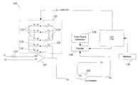
- FIG. 1is a diagram of one embodiment of a tuning circuit 100 configured according to the present invention.
- tuning circuit 100includes an op-amp 102 , a resistor 110 , and a capacitor array 120 .
- the op-amp 102includes first and second inputs 104 and 106 , and an output 108 .
- the op-amp 102may be any kind of op-amp known in the art.
- the resistor 110has an arbitrary design value and is coupled to the first input 104 of the op-amp. In one embodiment, the resistor value is 265.08 k ⁇ , however due to fabrication errors in the manufacturing process, a resistor's value may vary by as much as ⁇ 20% of the design value for current CMOS IC fabrication.
- the capacitor array 120is coupled in a feedback path between the first input 104 and the op-amp output 108 .
- the capacitor array 120includes a plurality of capacitors 124 (C 1 -C N ) connected in parallel to each other, each capacitor having a particular value, and each of the plurality of capacitors 124 having a corresponding switches 122 (S 1 -S N ).
- capacitor array 120further has a base capacitor value C b 129 , with an associated switch 128 (S b ).
- the capacitance values of the plurality of capacitors 124 in the capacitor array 120should be such that when switched together in combination, at least one combination of values will provide an optimal capacitance required by a filter circuit, thus producing a tuning effect that will tune the filter circuit as close as possible to a predetermined RC value.
- the predetermined RC valueis arbitrary and is determined by the design rules of the circuit
- the capacitor array 120consists of 16 capacitors (including the base capacitor) with the following values:
- one switch 126does not have a corresponding capacitor and creates a short circuit across the capacitor array when closed to initialize the capacitor array 120 .
- switch 126When switch 126 is closed and switches 122 and 128 are closed, the plurality of capacitors 122 and 129 discharge, or reset.
- switch 126may also be referred to, herein, as a reset switch.
- the tuning circuit 100further includes a CPU 170 , a clock signal generator 150 , a memory 130 , and a counter 140 .
- the CPU 170is used to control which switches are to be opened and closed.
- the clock signal generator 150may be any kind of clock signal generator known in the art, such as a crystal oscillator, and is configured to produce a clock signal with a certain frequency.
- the frequency of the clock signalcan be arbitrary, but may be determined by design rules.
- the clock signalhas a frequency of 24 MHz.
- the memory 130is used to store the codes which the CPU 170 will execute.
- the clock signal generator 150produces a clock signal at a predetermined frequency (e.g., 24 MHz).
- the counter 140is configured to determine the number of cycles of the clock signal that occur during a measurable time period corresponding to an RC time constant of the tuning circuit.
- the RC time constant of the tuning circuitis equivalent to the product of the resistance value of the resistor 110 and the capacitance value of the capacitor array 120 .
- the tuning circuit 100further includes a comparator 160 which is configured to generate an output signal to the counter 140 so that the corresponding RC time constant of the tuning circuit can be measured.
- a comparator 160which is configured to generate an output signal to the counter 140 so that the corresponding RC time constant of the tuning circuit can be measured.
- the desired RC time constantis equivalently represented, in terms of the number of clock cycles, by a predetermined number stored in memory.
- the predetermined numbermay be determined by design rules and may be the equivalent of the clock signal generator frequency multiplied by the designed RC value for the filter circuit.
- the predetermined RC time constanti.e. designed RC value
- the predetermined RC time constantis 2 ⁇ s. Exemplary embodiments of a method of utilizing the tuning circuit 100 will follow in further detail below.
- V 1 , V 2 and V 3when the tuning circuit 100 is in use, voltages V 1 , V 2 and V 3 must be provided.
- the voltages provided to op-amp 102 and comparator 160are denoted by V 1 , V 2 and V 3 where V 1 >V 2 >V 3 .
- the voltages V 1 , V 2 and V 3can be generated by using any state-of-art bias circuits.
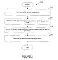
- FIG. 2is a flow diagram of one embodiment of a method 200 for tuning a filter circuit.
- Method 200begins, at processing block 202 , with determining a real RC time constant value (also referred to herein as an “RC value”) for the tuning circuit. This is the actual RC value according to the circuit as fabricated, not merely as designed.
- method 200continues, at processing block 204 , with comparing the real RC value to a predetermined RC value.
- the predetermined RC valueis the designed value of the time constant.
- method 200concludes, at processing block 206 by varying the real RC value (e.g., by opening and closing appropriate combinations of capacitor array switches 122 ) until the RC product equals, or closely approximates to within an acceptable error, the predetermined RC value. Method 200 may then continue, at processing block 208 , with applying the real RC value of the tuning circuit to the filter circuit. A method of finding the appropriate the RC value is described in further detail below in conjunction with FIG. 3 .
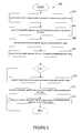
- FIG. 3is a flow diagram of one embodiment of a method 300 for varying a real RC value until it is closest to a predetermined RC value in a filter tuning circuit.
- Method 300begins, at processing block 302 , with varying the capacitance value (also referred to herein as “C value” or “C”) of the real RC value by a first increment to produce a first real RC value.
- Method 300continues, at processing block 304 , with varying the C value by a second increment to produce a second real RC value.
- Method 300then continues, at processing block 306 , with comparing the first and second real RC values to the predetermined RC value.
- Method 300concludes, at processing block 308 , with storing in a memory which ever of the first or second real RC value is closest to the predetermined RC value.
- method 300may further include, as shown in processing block 310 , varying the C value in further increments to produce subsequent real RC values (fourth, fifth, and so on). Then, at processing block 312 , method 300 may further include comparing the subsequent real RC values and the stored real RC value to the predetermined RC value. Finally, method 300 may further include, as shown in processing block 314 , storing in memory the subsequent real RC values if closer to the predetermined RC value than the stored real RC value. In one embodiment, the real RC value may be incremented up to 16 times. These increments correspond to different open/closed combinations of capacitor array switches 122 and 128 .
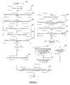
- FIG. 4is a flow diagram of one embodiment of a method 400 for tuning a filter circuit.
- Method 400utilizes elements described in conjunction with tuning circuit 100 further above.
- method 400begins, at processing block 402 , with initializing the capacitor array 120 .
- Initializing the capacitor array 120includes closing all the switches in the capacitor array 122 and 128 , then closing the reset switch 126 to discharge the base capacitor 129 and the plurality of capacitors 124 . In one embodiment, it is advantageous to wait at least one microsecond for the capacitors to discharge.
- method 400continues, at processing block 404 , with switching (closing and/or opening) a first combination of switches to provide a first capacitance in the capacitor array 120 .
- the combination of switchescan be determined by a computing algorithm stored in memory 130 and effectuated by CPU 170 .
- a (4+1)-bit control linemay be connected to the CPU 170 and configured to switch the capacitors in 16 different combinations (4 bits) as well as to control the reset switch (1 bit).
- method 400continues with measuring the RC time constant corresponding to the first capacitance value.
- An exemplary method 500 of measuring the RC timefollows, is shown in FIG. 5 .
- method 500includes opening the reset switch immediately after, or simultaneously with, the switching of the first combination of switches.
- method 500continues, as shown in processing block 504 , with starting the counter 140 immediately after, or simultaneously with, the opening of the reset switch.
- the combination of switched capacitors in the capacitor array 120will charge, causing output 108 to decrease as time passes.
- Method 500may then continue, as shown at processing block 506 , by stopping the counter 140 once the capacitors in the capacitor array 120 have charged.
- the time it takes for the capacitor combination to chargecorresponds to the RC time constant of the capacitor combination.
- the comparator 160can be configured to so that the voltage signal (V 3 ) received at the first comparator input 112 is at a low level thus causing the output 109 of the comparator 160 to go high when the output of the op-amp 108 drops below the other comparator input voltage signal (V 3 ).
- the counter 140will stop counting.
- the counter 140then has stored in it the number of clock cycles that cycled during the charging of the first combination of switched capacitors. This number of clock cycles represents the measurable time period it takes for the first combination of switched capacitors to reach their real RC time constant value.
- method 400continues with determining an RC time constant for the first capacitance value.
- the RC time constantis determined by the multiplying the value of the resistor 110 , the capacitance value of the capacitor array 120 for any given capacitor combination, and the design value (V 2 -V 3 )/(V 1 -V 2 ).
- capacitor array 120may have 16 different capacitors (i.e. C b and C 1 -C 15 ).
- a (4+1)-bit control linemay also be used to switch the capacitors in 16 different combinations (4 bits) as well as to control the reset switch (1 bit).
- One exemplary combinationwould be, for instance, when capacitor array switches S b , S 1 , S 2 and S 3 are switched on (which corresponding to the case of 4 bit control signal equal to 3).
- the corresponding RC time constant valuewould be the real resistance value (e.g. 265.08 k ⁇ manufacturing error ) multiplied by the sum of C b (e.g. 5.4529 pF ⁇ manufacturing error), C 1 (e.g. 419.454 fF ⁇ manufacturing error), C 2 (e.g. 419.454 fF ⁇ manufacturing error), and C 3 (e.g.
- the first RC time constanthas a measurable time period (e.g. 1.809 ⁇ s).
- method 400continues, at processing block 410 , with determining a first number of cycles of a clock signal.
- the clock signal generator 150produces the clock signal at a particular frequency (e.g. 24 MHz).
- the number of cyclesis computed by multiplying the frequency of the clock signal generator 150 (e.g. 24 MHz) by the measurable time period of the first RC time constant (e.g.
- the number of cyclesis a scalar value.
- method 400continues, at processing step 412 , with comparing the first number of cycles (e.g., Y ⁇ 24 MHz, or 43) to a predetermined number of cycles.
- the predetermined RC valueis the designed RC value for a filter circuit.
- the predetermined number of cyclesalso results in a scalar value and may be stored in memory 130 .
- the scalar valuesmay each be stored in registers and compared to each other using hardware logic.
- method 400may continue in various ways depending on the outcome.
- method 400may continue, at processing block 414 , with storing the bit value associated with the first combination and ending the process (e.g., storing the bit value of the control line that corresponds to the combination of switched switches S b , S 1 , S 2 and S 3 ).
- method 400may continue, as shown in processing blocks 416 - 422 with (1) storing the bit value of the first combination, (2) closing a second combination of switches to produce a second capacitance value, (3) turning on the clock signal generator and determining a second number of cycles, and (4) comparing the second number of cycles to the predetermined number of cycles.
- the predetermined number of cyclese.g., Y ⁇ 24 MHz ⁇ 2 ⁇ s ⁇ 24 MHz
- the CPU 170may intelligently compare how close the first number of cycles was to the predetermined number of cycles and accordingly compute a second combination that will attempt to bring the second number of cycles closer to the predetermined number of cycles than the first. For instance, if the first number of cycles is 43, as shown in the example above, and the predetermined number of cycles is 48, then the CPU 170 can determine that 43 is lower than 48 and thus determine that the capacitance value of the capacitor array 120 must increase (i.e., switch on more capacitors, or switch off lower valued capacitors and switch on higher valued capacitors.)
- method 400may continue, at processing block 424 , with storing the bit value associated with the second combination. If, however, the second number of cycles is not closer to the predetermined number of cycles than the first number of cycles, then method 400 may continue, as shown in processing block 426 , with repeating for subsequent combinations until one of the subsequent combinations of capacitance values produces a number of cycles equal to the predetermined number of cycles. In one embodiment, repeating may occur for a limited number of combinations until a subsequent value of clock cycles closely approximates the predetermined number of cycles (e.g., within an acceptable error tolerance). Then, at processing block 428 , method 400 continues with storing the bit value of the subsequent combination associated with the subsequent number of cycles equal to, or most approximately equal to, the predetermined number of cycles.
- a filter circuitmay have an RC filter design with a capacitor array similar to that of the tuning circuit.
- Method 400may continue, as shown in processing block 430 , with applying the bit value associated with any one of the first, second, or subsequent combination of switches to a capacitor array of a filter circuit.
- the filter circuitmay have a similar capacitor array and resistor as those of the tuning circuit, thus the RC value can be applied to the filter circuit by switching the capacitors in the capacitor array of the filter circuit to have the same switched configuration as the capacitors in the capacitor array of the tuning circuit.
- the filter circuitwill have an RC response equal to, or very close to, that of the filter circuit, which should approximate that of the designed RC response.
Landscapes
- Networks Using Active Elements (AREA)
- Measurement Of Resistance Or Impedance (AREA)
Abstract
Description
| Cb= 5.4529 pF | C1= 419.454 fF | C2= 419.454 fF | C3= |
| 209.727 fF | |||
| C4= 209.727 fF | C5= 209.727 fF | C6= 209.727 fF | C7= |
| 209.727 fF | |||
| C8= 209.727 fF | C9= 419.454 fF | C10= 419.454 fF | C11= |
| 419.454 fF | |||
| C12= 419.454 fF | C13= 629.18 fF | C14= 629.18 fF | C15= |
| 629.18 fF | |||


Claims (13)
Priority Applications (2)
| Application Number | Priority Date | Filing Date | Title |
|---|---|---|---|
| US10/051,416US6677814B2 (en) | 2002-01-17 | 2002-01-17 | Method and apparatus for filter tuning |
| PCT/US2003/001302WO2003063352A1 (en) | 2002-01-17 | 2003-01-15 | Method and apparatus for filter tuning |
Applications Claiming Priority (1)
| Application Number | Priority Date | Filing Date | Title |
|---|---|---|---|
| US10/051,416US6677814B2 (en) | 2002-01-17 | 2002-01-17 | Method and apparatus for filter tuning |
Publications (2)
| Publication Number | Publication Date |
|---|---|
| US20030132799A1 US20030132799A1 (en) | 2003-07-17 |
| US6677814B2true US6677814B2 (en) | 2004-01-13 |
Family
ID=21971168
Family Applications (1)
| Application Number | Title | Priority Date | Filing Date |
|---|---|---|---|
| US10/051,416Expired - LifetimeUS6677814B2 (en) | 2002-01-17 | 2002-01-17 | Method and apparatus for filter tuning |
Country Status (2)
| Country | Link |
|---|---|
| US (1) | US6677814B2 (en) |
| WO (1) | WO2003063352A1 (en) |
Cited By (67)
| Publication number | Priority date | Publication date | Assignee | Title |
|---|---|---|---|---|
| US20040155703A1 (en)* | 2003-01-28 | 2004-08-12 | Stmicroelectronics S.A. | Method and circuit for correcting the offset of an amplification chain |
| US6842710B1 (en)* | 2002-08-22 | 2005-01-11 | Cypress Semiconductor Corporation | Calibration of integrated circuit time constants |
| US20050242873A1 (en)* | 2004-04-30 | 2005-11-03 | Hung-I Chen | Frequency tuning loop for active RC filters |
| US20050253646A1 (en)* | 2004-05-14 | 2005-11-17 | Joanna Lin | Global Automatic RC Time Constant Tuning Circuit and Method for on Chip RC Filters |
| US7002404B2 (en)* | 2003-02-27 | 2006-02-21 | Infineon Technologies Ag | Tuning circuit for a filter |
| US7019586B2 (en)* | 2004-03-23 | 2006-03-28 | Silicon Laboratories Inc. | High-speed Gm-C tuning |
| US20060119400A1 (en)* | 2004-12-06 | 2006-06-08 | Frank Ohnhauser | Window comparator and method of providing a window comparator function |
| US7078961B2 (en)* | 2003-05-12 | 2006-07-18 | Infineon Technologies Ag | Device and method for calibrating R/C filter circuits |
| US20060214725A1 (en)* | 2005-03-25 | 2006-09-28 | Rotchford Chris J | Digital time constant tracking technique and apparatus |
| US20060294523A1 (en)* | 2005-06-23 | 2006-12-28 | Paul Beard | Touch wake for electronic devices |
| US20070008046A1 (en)* | 2005-07-07 | 2007-01-11 | Freescale Semiconductor, Inc. | Baseband RC filter pole and on-chip current tracking system |
| US7176754B2 (en)* | 2003-02-26 | 2007-02-13 | Stmicroelectronics, S.R.L. | Control system for the characteristic parameters of an active filter |
| US20070043540A1 (en)* | 2005-06-30 | 2007-02-22 | Cleland Donald A | Adaptive energy performance monitoring and control system |
| US7212068B2 (en)* | 2004-04-02 | 2007-05-01 | Integration Associates Inc. | Tunable Sallen-Key filter stage and filter assembly |
| US20070109063A1 (en)* | 2005-11-14 | 2007-05-17 | Wai Lau | On-chip R-C time constant calibration |
| US20070127169A1 (en)* | 2005-12-07 | 2007-06-07 | Rambus, Inc. | Integrated circuit with configurable bypass capacitance |
| US20080096514A1 (en)* | 2006-10-18 | 2008-04-24 | Freescale Semiconductor, Inc. | Controlling the bandwidth of an analog filter |
| US20080191795A1 (en)* | 2007-02-08 | 2008-08-14 | Mediatek Singapore Pte Ltd | Method and apparatus for tuning an active filter |
| US20080191794A1 (en)* | 2007-02-08 | 2008-08-14 | Mediatek Inc. | Method and apparatus for tuning an active filter |
| US20080258804A1 (en)* | 2007-04-17 | 2008-10-23 | Cypress Semiconductor Corporation | Numerical band gap |
| US20090066540A1 (en)* | 2007-09-07 | 2009-03-12 | Dimitri Marinakis | Centralized route calculation for a multi-hop streetlight network |
| US20090066258A1 (en)* | 2007-09-07 | 2009-03-12 | Streetlight Intelligence, Inc. | Streelight monitoring and control |
| US20100013546A1 (en)* | 2006-12-01 | 2010-01-21 | Jung-Hoon Yoo | Systems and methods for filter tuning using binary search algorithm |
| US20100073048A1 (en)* | 2008-09-24 | 2010-03-25 | Mediatek Inc. | Phase locked loop and calibration method |
| US7737724B2 (en) | 2007-04-17 | 2010-06-15 | Cypress Semiconductor Corporation | Universal digital block interconnection and channel routing |
| US7761845B1 (en) | 2002-09-09 | 2010-07-20 | Cypress Semiconductor Corporation | Method for parameterizing a user module |
| US7765095B1 (en) | 2000-10-26 | 2010-07-27 | Cypress Semiconductor Corporation | Conditional branching in an in-circuit emulation system |
| US7770113B1 (en) | 2001-11-19 | 2010-08-03 | Cypress Semiconductor Corporation | System and method for dynamically generating a configuration datasheet |
| US7774190B1 (en) | 2001-11-19 | 2010-08-10 | Cypress Semiconductor Corporation | Sleep and stall in an in-circuit emulation system |
| US7816978B1 (en) | 2009-07-20 | 2010-10-19 | Mediatek Inc. | Operating circuit with RC calibration and RC calibration method |
| US7825688B1 (en) | 2000-10-26 | 2010-11-02 | Cypress Semiconductor Corporation | Programmable microcontroller architecture(mixed analog/digital) |
| US7825715B1 (en)* | 2008-10-03 | 2010-11-02 | Marvell International Ltd. | Digitally tunable capacitor |
| US7844437B1 (en) | 2001-11-19 | 2010-11-30 | Cypress Semiconductor Corporation | System and method for performing next placements and pruning of disallowed placements for programming an integrated circuit |
| US7893724B2 (en) | 2004-03-25 | 2011-02-22 | Cypress Semiconductor Corporation | Method and circuit for rapid alignment of signals |
| US20110057570A1 (en)* | 2005-06-30 | 2011-03-10 | Streetlight Intelligence, Inc. | Method and System for Luminance Characterization |
| US7952425B2 (en) | 2008-09-11 | 2011-05-31 | Siemens Medical Solutions Usa, Inc. | Adaptive filtering system for patient signal monitoring |
| US8026739B2 (en) | 2007-04-17 | 2011-09-27 | Cypress Semiconductor Corporation | System level interconnect with programmable switching |
| US8040266B2 (en) | 2007-04-17 | 2011-10-18 | Cypress Semiconductor Corporation | Programmable sigma-delta analog-to-digital converter |
| US8049569B1 (en) | 2007-09-05 | 2011-11-01 | Cypress Semiconductor Corporation | Circuit and method for improving the accuracy of a crystal-less oscillator having dual-frequency modes |
| US8067948B2 (en) | 2006-03-27 | 2011-11-29 | Cypress Semiconductor Corporation | Input/output multiplexer bus |
| US8069436B2 (en) | 2004-08-13 | 2011-11-29 | Cypress Semiconductor Corporation | Providing hardware independence to automate code generation of processing device firmware |
| US8069428B1 (en) | 2001-10-24 | 2011-11-29 | Cypress Semiconductor Corporation | Techniques for generating microcontroller configuration information |
| US8069405B1 (en) | 2001-11-19 | 2011-11-29 | Cypress Semiconductor Corporation | User interface for efficiently browsing an electronic document using data-driven tabs |
| US8078894B1 (en) | 2007-04-25 | 2011-12-13 | Cypress Semiconductor Corporation | Power management architecture, method and configuration system |
| US8078970B1 (en) | 2001-11-09 | 2011-12-13 | Cypress Semiconductor Corporation | Graphical user interface with user-selectable list-box |
| US8085100B2 (en) | 2005-02-04 | 2011-12-27 | Cypress Semiconductor Corporation | Poly-phase frequency synthesis oscillator |
| US8085067B1 (en) | 2005-12-21 | 2011-12-27 | Cypress Semiconductor Corporation | Differential-to-single ended signal converter circuit and method |
| US8092083B2 (en) | 2007-04-17 | 2012-01-10 | Cypress Semiconductor Corporation | Temperature sensor with digital bandgap |
| US8103497B1 (en) | 2002-03-28 | 2012-01-24 | Cypress Semiconductor Corporation | External interface for event architecture |
| US8103496B1 (en) | 2000-10-26 | 2012-01-24 | Cypress Semicondutor Corporation | Breakpoint control in an in-circuit emulation system |
| US8120408B1 (en) | 2005-05-05 | 2012-02-21 | Cypress Semiconductor Corporation | Voltage controlled oscillator delay cell and method |
| US8149048B1 (en) | 2000-10-26 | 2012-04-03 | Cypress Semiconductor Corporation | Apparatus and method for programmable power management in a programmable analog circuit block |
| US8160864B1 (en) | 2000-10-26 | 2012-04-17 | Cypress Semiconductor Corporation | In-circuit emulator and pod synchronized boot |
| US8176296B2 (en) | 2000-10-26 | 2012-05-08 | Cypress Semiconductor Corporation | Programmable microcontroller architecture |
| US8286125B2 (en) | 2004-08-13 | 2012-10-09 | Cypress Semiconductor Corporation | Model for a hardware device-independent method of defining embedded firmware for programmable systems |
| US8402313B1 (en) | 2002-05-01 | 2013-03-19 | Cypress Semiconductor Corporation | Reconfigurable testing system and method |
| US8499270B1 (en) | 2007-04-25 | 2013-07-30 | Cypress Semiconductor Corporation | Configuration of programmable IC design elements |
| US8498606B1 (en)* | 2007-06-15 | 2013-07-30 | Marvell International Ltd. | Data rate tracking filter |
| US8516025B2 (en) | 2007-04-17 | 2013-08-20 | Cypress Semiconductor Corporation | Clock driven dynamic datapath chaining |
| US8533677B1 (en) | 2001-11-19 | 2013-09-10 | Cypress Semiconductor Corporation | Graphical user interface for dynamically reconfiguring a programmable device |
| US8692574B2 (en) | 2009-10-01 | 2014-04-08 | Rambus Inc. | Methods and systems for reducing supply and termination noise |
| US8862216B2 (en) | 2012-03-15 | 2014-10-14 | Siemens Medical Solutions Usa, Inc. | Adaptive cardiac data patient filter system |
| US9448964B2 (en) | 2009-05-04 | 2016-09-20 | Cypress Semiconductor Corporation | Autonomous control in a programmable system |
| US9564902B2 (en) | 2007-04-17 | 2017-02-07 | Cypress Semiconductor Corporation | Dynamically configurable and re-configurable data path |
| US9720805B1 (en) | 2007-04-25 | 2017-08-01 | Cypress Semiconductor Corporation | System and method for controlling a target device |
| US10698662B2 (en) | 2001-11-15 | 2020-06-30 | Cypress Semiconductor Corporation | System providing automatic source code generation for personalization and parameterization of user modules |
| US10849509B2 (en) | 2014-11-21 | 2020-12-01 | Siemens Healthcare Gmbh | Patient signal filtering |
Families Citing this family (2)
| Publication number | Priority date | Publication date | Assignee | Title |
|---|---|---|---|---|
| DE102006034581A1 (en)* | 2006-07-26 | 2008-01-31 | Infineon Technologies Ag | Filter device i.e. second order phase locked loop filter, has switched capacitor circuit arranged between input and output of operational amplifier, where capacitor circuit comprises capacitor and switching device |
| CN101926230B (en)* | 2008-01-24 | 2014-02-19 | 奥斯兰姆有限公司 | Electronic ballast and method for energizing at least one light source |
Citations (4)
| Publication number | Priority date | Publication date | Assignee | Title |
|---|---|---|---|---|
| US5187445A (en)* | 1991-10-28 | 1993-02-16 | Motorola, Inc. | Tuning circuit for continuous-time filters and method therefor |
| US5245646A (en)* | 1992-06-01 | 1993-09-14 | Motorola, Inc. | Tuning circuit for use with an integrated continuous time analog filter |
| US5625316A (en) | 1994-07-01 | 1997-04-29 | Motorola, Inc. | Tuning circuit for an RC filter |
| US5914633A (en)* | 1997-08-08 | 1999-06-22 | Lucent Technologies Inc. | Method and apparatus for tuning a continuous time filter |
- 2002
- 2002-01-17USUS10/051,416patent/US6677814B2/ennot_activeExpired - Lifetime
- 2003
- 2003-01-15WOPCT/US2003/001302patent/WO2003063352A1/ennot_activeApplication Discontinuation
Patent Citations (4)
| Publication number | Priority date | Publication date | Assignee | Title |
|---|---|---|---|---|
| US5187445A (en)* | 1991-10-28 | 1993-02-16 | Motorola, Inc. | Tuning circuit for continuous-time filters and method therefor |
| US5245646A (en)* | 1992-06-01 | 1993-09-14 | Motorola, Inc. | Tuning circuit for use with an integrated continuous time analog filter |
| US5625316A (en) | 1994-07-01 | 1997-04-29 | Motorola, Inc. | Tuning circuit for an RC filter |
| US5914633A (en)* | 1997-08-08 | 1999-06-22 | Lucent Technologies Inc. | Method and apparatus for tuning a continuous time filter |
Non-Patent Citations (1)
| Title |
|---|
| PCT Search Report for PCT/US 03/01302, 5 pages, Jun. 3, 2003. |
Cited By (100)
| Publication number | Priority date | Publication date | Assignee | Title |
|---|---|---|---|---|
| US10248604B2 (en) | 2000-10-26 | 2019-04-02 | Cypress Semiconductor Corporation | Microcontroller programmable system on a chip |
| US8358150B1 (en) | 2000-10-26 | 2013-01-22 | Cypress Semiconductor Corporation | Programmable microcontroller architecture(mixed analog/digital) |
| US8176296B2 (en) | 2000-10-26 | 2012-05-08 | Cypress Semiconductor Corporation | Programmable microcontroller architecture |
| US8160864B1 (en) | 2000-10-26 | 2012-04-17 | Cypress Semiconductor Corporation | In-circuit emulator and pod synchronized boot |
| US8149048B1 (en) | 2000-10-26 | 2012-04-03 | Cypress Semiconductor Corporation | Apparatus and method for programmable power management in a programmable analog circuit block |
| US8555032B2 (en) | 2000-10-26 | 2013-10-08 | Cypress Semiconductor Corporation | Microcontroller programmable system on a chip with programmable interconnect |
| US8103496B1 (en) | 2000-10-26 | 2012-01-24 | Cypress Semicondutor Corporation | Breakpoint control in an in-circuit emulation system |
| US10261932B2 (en) | 2000-10-26 | 2019-04-16 | Cypress Semiconductor Corporation | Microcontroller programmable system on a chip |
| US7765095B1 (en) | 2000-10-26 | 2010-07-27 | Cypress Semiconductor Corporation | Conditional branching in an in-circuit emulation system |
| US8736303B2 (en) | 2000-10-26 | 2014-05-27 | Cypress Semiconductor Corporation | PSOC architecture |
| US9843327B1 (en) | 2000-10-26 | 2017-12-12 | Cypress Semiconductor Corporation | PSOC architecture |
| US9766650B2 (en) | 2000-10-26 | 2017-09-19 | Cypress Semiconductor Corporation | Microcontroller programmable system on a chip with programmable interconnect |
| US10725954B2 (en) | 2000-10-26 | 2020-07-28 | Monterey Research, Llc | Microcontroller programmable system on a chip |
| US10020810B2 (en) | 2000-10-26 | 2018-07-10 | Cypress Semiconductor Corporation | PSoC architecture |
| US7825688B1 (en) | 2000-10-26 | 2010-11-02 | Cypress Semiconductor Corporation | Programmable microcontroller architecture(mixed analog/digital) |
| US8793635B1 (en) | 2001-10-24 | 2014-07-29 | Cypress Semiconductor Corporation | Techniques for generating microcontroller configuration information |
| US8069428B1 (en) | 2001-10-24 | 2011-11-29 | Cypress Semiconductor Corporation | Techniques for generating microcontroller configuration information |
| US10466980B2 (en) | 2001-10-24 | 2019-11-05 | Cypress Semiconductor Corporation | Techniques for generating microcontroller configuration information |
| US8078970B1 (en) | 2001-11-09 | 2011-12-13 | Cypress Semiconductor Corporation | Graphical user interface with user-selectable list-box |
| US10698662B2 (en) | 2001-11-15 | 2020-06-30 | Cypress Semiconductor Corporation | System providing automatic source code generation for personalization and parameterization of user modules |
| US7770113B1 (en) | 2001-11-19 | 2010-08-03 | Cypress Semiconductor Corporation | System and method for dynamically generating a configuration datasheet |
| US8533677B1 (en) | 2001-11-19 | 2013-09-10 | Cypress Semiconductor Corporation | Graphical user interface for dynamically reconfiguring a programmable device |
| US8069405B1 (en) | 2001-11-19 | 2011-11-29 | Cypress Semiconductor Corporation | User interface for efficiently browsing an electronic document using data-driven tabs |
| US8370791B2 (en) | 2001-11-19 | 2013-02-05 | Cypress Semiconductor Corporation | System and method for performing next placements and pruning of disallowed placements for programming an integrated circuit |
| US7844437B1 (en) | 2001-11-19 | 2010-11-30 | Cypress Semiconductor Corporation | System and method for performing next placements and pruning of disallowed placements for programming an integrated circuit |
| US7774190B1 (en) | 2001-11-19 | 2010-08-10 | Cypress Semiconductor Corporation | Sleep and stall in an in-circuit emulation system |
| US8103497B1 (en) | 2002-03-28 | 2012-01-24 | Cypress Semiconductor Corporation | External interface for event architecture |
| US8402313B1 (en) | 2002-05-01 | 2013-03-19 | Cypress Semiconductor Corporation | Reconfigurable testing system and method |
| US6842710B1 (en)* | 2002-08-22 | 2005-01-11 | Cypress Semiconductor Corporation | Calibration of integrated circuit time constants |
| US7761845B1 (en) | 2002-09-09 | 2010-07-20 | Cypress Semiconductor Corporation | Method for parameterizing a user module |
| US20040155703A1 (en)* | 2003-01-28 | 2004-08-12 | Stmicroelectronics S.A. | Method and circuit for correcting the offset of an amplification chain |
| US7057452B2 (en)* | 2003-01-28 | 2006-06-06 | Stmicroelectronics S.A. | Method and circuit for correcting the offset of an amplification chain |
| US7176754B2 (en)* | 2003-02-26 | 2007-02-13 | Stmicroelectronics, S.R.L. | Control system for the characteristic parameters of an active filter |
| US7002404B2 (en)* | 2003-02-27 | 2006-02-21 | Infineon Technologies Ag | Tuning circuit for a filter |
| US7078961B2 (en)* | 2003-05-12 | 2006-07-18 | Infineon Technologies Ag | Device and method for calibrating R/C filter circuits |
| US7019586B2 (en)* | 2004-03-23 | 2006-03-28 | Silicon Laboratories Inc. | High-speed Gm-C tuning |
| US7893724B2 (en) | 2004-03-25 | 2011-02-22 | Cypress Semiconductor Corporation | Method and circuit for rapid alignment of signals |
| US7212068B2 (en)* | 2004-04-02 | 2007-05-01 | Integration Associates Inc. | Tunable Sallen-Key filter stage and filter assembly |
| US7279962B2 (en)* | 2004-04-30 | 2007-10-09 | Industrial Technology Research Institute | Frequency tuning loop for active RC filters |
| US20050242873A1 (en)* | 2004-04-30 | 2005-11-03 | Hung-I Chen | Frequency tuning loop for active RC filters |
| US20050253646A1 (en)* | 2004-05-14 | 2005-11-17 | Joanna Lin | Global Automatic RC Time Constant Tuning Circuit and Method for on Chip RC Filters |
| US8069436B2 (en) | 2004-08-13 | 2011-11-29 | Cypress Semiconductor Corporation | Providing hardware independence to automate code generation of processing device firmware |
| US8286125B2 (en) | 2004-08-13 | 2012-10-09 | Cypress Semiconductor Corporation | Model for a hardware device-independent method of defining embedded firmware for programmable systems |
| US20060119400A1 (en)* | 2004-12-06 | 2006-06-08 | Frank Ohnhauser | Window comparator and method of providing a window comparator function |
| US7157945B2 (en)* | 2004-12-06 | 2007-01-02 | Texas Instruments Incorporated | Window comparator and method of providing a window comparator function |
| US8085100B2 (en) | 2005-02-04 | 2011-12-27 | Cypress Semiconductor Corporation | Poly-phase frequency synthesis oscillator |
| US7190213B2 (en) | 2005-03-25 | 2007-03-13 | Freescale Semiconductor, Inc. | Digital time constant tracking technique and apparatus |
| US20060214725A1 (en)* | 2005-03-25 | 2006-09-28 | Rotchford Chris J | Digital time constant tracking technique and apparatus |
| US8120408B1 (en) | 2005-05-05 | 2012-02-21 | Cypress Semiconductor Corporation | Voltage controlled oscillator delay cell and method |
| US8089461B2 (en) | 2005-06-23 | 2012-01-03 | Cypress Semiconductor Corporation | Touch wake for electronic devices |
| US20060294523A1 (en)* | 2005-06-23 | 2006-12-28 | Paul Beard | Touch wake for electronic devices |
| US8264156B2 (en) | 2005-06-30 | 2012-09-11 | Led Roadway Lighting Ltd. | Method and system for luminance characterization |
| US20110057570A1 (en)* | 2005-06-30 | 2011-03-10 | Streetlight Intelligence, Inc. | Method and System for Luminance Characterization |
| US20070043540A1 (en)* | 2005-06-30 | 2007-02-22 | Cleland Donald A | Adaptive energy performance monitoring and control system |
| US9144135B2 (en) | 2005-06-30 | 2015-09-22 | Led Roadway Lighting Ltd. | Adaptive energy performance monitoring and control system |
| US8433426B2 (en) | 2005-06-30 | 2013-04-30 | Led Roadway Lighting Ltd | Adaptive energy performance monitoring and control system |
| US20070008046A1 (en)* | 2005-07-07 | 2007-01-11 | Freescale Semiconductor, Inc. | Baseband RC filter pole and on-chip current tracking system |
| US7339442B2 (en) | 2005-07-07 | 2008-03-04 | Freescale Semiconductor, Inc. | Baseband RC filter pole and on-chip current tracking system |
| US7548129B2 (en)* | 2005-11-14 | 2009-06-16 | Quantek, Inc. | On-chip R-C time constant calibration |
| US20070109063A1 (en)* | 2005-11-14 | 2007-05-17 | Wai Lau | On-chip R-C time constant calibration |
| US20070127169A1 (en)* | 2005-12-07 | 2007-06-07 | Rambus, Inc. | Integrated circuit with configurable bypass capacitance |
| US8085067B1 (en) | 2005-12-21 | 2011-12-27 | Cypress Semiconductor Corporation | Differential-to-single ended signal converter circuit and method |
| US8067948B2 (en) | 2006-03-27 | 2011-11-29 | Cypress Semiconductor Corporation | Input/output multiplexer bus |
| US8717042B1 (en) | 2006-03-27 | 2014-05-06 | Cypress Semiconductor Corporation | Input/output multiplexer bus |
| US20080096514A1 (en)* | 2006-10-18 | 2008-04-24 | Freescale Semiconductor, Inc. | Controlling the bandwidth of an analog filter |
| US7937058B2 (en) | 2006-10-18 | 2011-05-03 | Freescale Semiconductor, Inc. | Controlling the bandwidth of an analog filter |
| US20100013546A1 (en)* | 2006-12-01 | 2010-01-21 | Jung-Hoon Yoo | Systems and methods for filter tuning using binary search algorithm |
| US7944286B2 (en)* | 2006-12-01 | 2011-05-17 | Xronet Corporation | Systems and methods for filter tuning using binary search algorithm |
| US7477098B2 (en)* | 2007-02-08 | 2009-01-13 | Mediatek Singapore Pte Ltd | Method and apparatus for tuning an active filter |
| US20080191794A1 (en)* | 2007-02-08 | 2008-08-14 | Mediatek Inc. | Method and apparatus for tuning an active filter |
| US20080191795A1 (en)* | 2007-02-08 | 2008-08-14 | Mediatek Singapore Pte Ltd | Method and apparatus for tuning an active filter |
| US20080258804A1 (en)* | 2007-04-17 | 2008-10-23 | Cypress Semiconductor Corporation | Numerical band gap |
| US8026739B2 (en) | 2007-04-17 | 2011-09-27 | Cypress Semiconductor Corporation | System level interconnect with programmable switching |
| US9564902B2 (en) | 2007-04-17 | 2017-02-07 | Cypress Semiconductor Corporation | Dynamically configurable and re-configurable data path |
| US8092083B2 (en) | 2007-04-17 | 2012-01-10 | Cypress Semiconductor Corporation | Temperature sensor with digital bandgap |
| US8516025B2 (en) | 2007-04-17 | 2013-08-20 | Cypress Semiconductor Corporation | Clock driven dynamic datapath chaining |
| US7737724B2 (en) | 2007-04-17 | 2010-06-15 | Cypress Semiconductor Corporation | Universal digital block interconnection and channel routing |
| US8130025B2 (en) | 2007-04-17 | 2012-03-06 | Cypress Semiconductor Corporation | Numerical band gap |
| US8040266B2 (en) | 2007-04-17 | 2011-10-18 | Cypress Semiconductor Corporation | Programmable sigma-delta analog-to-digital converter |
| US8476928B1 (en) | 2007-04-17 | 2013-07-02 | Cypress Semiconductor Corporation | System level interconnect with programmable switching |
| US9720805B1 (en) | 2007-04-25 | 2017-08-01 | Cypress Semiconductor Corporation | System and method for controlling a target device |
| US8078894B1 (en) | 2007-04-25 | 2011-12-13 | Cypress Semiconductor Corporation | Power management architecture, method and configuration system |
| US8499270B1 (en) | 2007-04-25 | 2013-07-30 | Cypress Semiconductor Corporation | Configuration of programmable IC design elements |
| US8909960B1 (en) | 2007-04-25 | 2014-12-09 | Cypress Semiconductor Corporation | Power management architecture, method and configuration system |
| US8498606B1 (en)* | 2007-06-15 | 2013-07-30 | Marvell International Ltd. | Data rate tracking filter |
| US8049569B1 (en) | 2007-09-05 | 2011-11-01 | Cypress Semiconductor Corporation | Circuit and method for improving the accuracy of a crystal-less oscillator having dual-frequency modes |
| US8570190B2 (en) | 2007-09-07 | 2013-10-29 | Led Roadway Lighting Ltd. | Centralized route calculation for a multi-hop streetlight network |
| US20090066258A1 (en)* | 2007-09-07 | 2009-03-12 | Streetlight Intelligence, Inc. | Streelight monitoring and control |
| US20090066540A1 (en)* | 2007-09-07 | 2009-03-12 | Dimitri Marinakis | Centralized route calculation for a multi-hop streetlight network |
| US8694256B2 (en) | 2007-09-07 | 2014-04-08 | Led Roadway Lighting Ltd. | Streetlight monitoring and control |
| US8290710B2 (en)* | 2007-09-07 | 2012-10-16 | Led Roadway Lighting Ltd. | Streetlight monitoring and control |
| US7952425B2 (en) | 2008-09-11 | 2011-05-31 | Siemens Medical Solutions Usa, Inc. | Adaptive filtering system for patient signal monitoring |
| US20100073048A1 (en)* | 2008-09-24 | 2010-03-25 | Mediatek Inc. | Phase locked loop and calibration method |
| US7825715B1 (en)* | 2008-10-03 | 2010-11-02 | Marvell International Ltd. | Digitally tunable capacitor |
| US9448964B2 (en) | 2009-05-04 | 2016-09-20 | Cypress Semiconductor Corporation | Autonomous control in a programmable system |
| US7816978B1 (en) | 2009-07-20 | 2010-10-19 | Mediatek Inc. | Operating circuit with RC calibration and RC calibration method |
| US8692574B2 (en) | 2009-10-01 | 2014-04-08 | Rambus Inc. | Methods and systems for reducing supply and termination noise |
| US9059695B2 (en) | 2009-10-01 | 2015-06-16 | Rambus Inc. | Methods and systems for reducing supply and termination noise |
| US8862216B2 (en) | 2012-03-15 | 2014-10-14 | Siemens Medical Solutions Usa, Inc. | Adaptive cardiac data patient filter system |
| US10849509B2 (en) | 2014-11-21 | 2020-12-01 | Siemens Healthcare Gmbh | Patient signal filtering |
Also Published As
| Publication number | Publication date |
|---|---|
| WO2003063352A1 (en) | 2003-07-31 |
| US20030132799A1 (en) | 2003-07-17 |
Similar Documents
| Publication | Publication Date | Title |
|---|---|---|
| US6677814B2 (en) | Method and apparatus for filter tuning | |
| US6842710B1 (en) | Calibration of integrated circuit time constants | |
| US7477098B2 (en) | Method and apparatus for tuning an active filter | |
| US11544349B2 (en) | Method for combining analog neural net with FPGA routing in a monolithic integrated circuit | |
| US6728891B2 (en) | Method and circuit for performing automatic power on reset of an integrated circuit | |
| JP3340373B2 (en) | Integrated circuit with programmable internal clock | |
| KR100284109B1 (en) | Precision RC Oscillator with Peak-Peak Voltage Control | |
| US20080191794A1 (en) | Method and apparatus for tuning an active filter | |
| JPH0496505A (en) | Cr oscillator | |
| US6894501B1 (en) | Selecting multiple settings for an integrated circuit function using a single integrated circuit terminal | |
| US8364433B1 (en) | Accurate resistance capacitance (RC) time constant calibration with metal-oxide-metal (MOM) capacitors for precision frequency response of integrated filters | |
| US10581438B2 (en) | Digitally reconfigurable ultra-high precision internal oscillator | |
| US6903602B2 (en) | Calibrated fully differential RC filter | |
| US20050035772A1 (en) | Method and device for determining the ratio between an RC time constant in an integrated circuit and a set value | |
| US5721501A (en) | Frequency multiplier and semiconductor integrated circuit employing the same | |
| US6825490B1 (en) | On chip resistor calibration structure and method | |
| JPH10229326A (en) | Frequency adjustment device for oscillation circuit | |
| US8258798B2 (en) | On chip duty cycle measurement module | |
| US12028034B2 (en) | Accurate calibration of analog integrated-circuits continuous-time complex filters | |
| US7548129B2 (en) | On-chip R-C time constant calibration | |
| JP4492907B2 (en) | PLL circuit, lock determination circuit thereof, and test method and apparatus | |
| US7880518B2 (en) | Method and apparatus for measuring and compensating for static phase error in phase locked loops | |
| JPH10229327A (en) | Frequency adjustment device for oscillation circuit | |
| CN100438335C (en) | Circuit and method for automatically coordinating resistance-capacitance time constant of semiconductor element | |
| US10969416B2 (en) | System and method of duplicate circuit block swapping for noise reduction |
Legal Events
| Date | Code | Title | Description |
|---|---|---|---|
| AS | Assignment | Owner name:TRANSILLICA, INC., CALIFORNIA Free format text:ASSIGNMENT OF ASSIGNORS INTEREST;ASSIGNORS:LOW, ENG CHUAN;CHEAH, JONATHON;YANG, SHIH-TSUNG;AND OTHERS;REEL/FRAME:012593/0392 Effective date:20020411 | |
| AS | Assignment | Owner name:MICROTUNE (SAN DIEGO), INC., CALIFORNIA Free format text:CHANGE OF NAME;ASSIGNOR:TRANSILICA INC.;REEL/FRAME:013675/0084 Effective date:20020701 | |
| FEPP | Fee payment procedure | Free format text:PAYOR NUMBER ASSIGNED (ORIGINAL EVENT CODE: ASPN); ENTITY STATUS OF PATENT OWNER: LARGE ENTITY Free format text:PAYER NUMBER DE-ASSIGNED (ORIGINAL EVENT CODE: RMPN); ENTITY STATUS OF PATENT OWNER: LARGE ENTITY | |
| STCF | Information on status: patent grant | Free format text:PATENTED CASE | |
| FPAY | Fee payment | Year of fee payment:4 | |
| AS | Assignment | Owner name:MICROTUNE, INC., TEXAS Free format text:MERGER;ASSIGNOR:MICROTUNE (SAN DIEGO), INC.;REEL/FRAME:025793/0877 Effective date:20101217 Owner name:ZORAN CORPORATION, CALIFORNIA Free format text:MERGER;ASSIGNOR:MICROTUNE, INC.;REEL/FRAME:025782/0047 Effective date:20101217 | |
| FPAY | Fee payment | Year of fee payment:8 | |
| AS | Assignment | Owner name:CSR TECHNOLOGY INC., CALIFORNIA Free format text:ASSIGNMENT OF ASSIGNORS INTEREST;ASSIGNOR:ZORAN CORPORATION;REEL/FRAME:027550/0695 Effective date:20120101 | |
| FPAY | Fee payment | Year of fee payment:12 | |
| AS | Assignment | Owner name:CSR TECHNOLOGY INC., CALIFORNIA Free format text:ASSIGNMENT OF ASSIGNORS INTEREST;ASSIGNOR:ZORAN CORPORATION;REEL/FRAME:036642/0395 Effective date:20150915 | |
| AS | Assignment | Owner name:QUALCOMM INCORPORATED, CALIFORNIA Free format text:ASSIGNMENT OF ASSIGNORS INTEREST;ASSIGNOR:CSR TECHNOLOGY INC.;REEL/FRAME:069221/0001 Effective date:20241004 |