US6677551B2 - Process for operating a plasma arc torch - Google Patents
Process for operating a plasma arc torchDownload PDFInfo
- Publication number
- US6677551B2 US6677551B2US10/200,865US20086502AUS6677551B2US 6677551 B2US6677551 B2US 6677551B2US 20086502 AUS20086502 AUS 20086502AUS 6677551 B2US6677551 B2US 6677551B2
- Authority
- US
- United States
- Prior art keywords
- plasma
- electrode
- gas
- flow
- post
- Prior art date
- Legal status (The legal status is an assumption and is not a legal conclusion. Google has not performed a legal analysis and makes no representation as to the accuracy of the status listed.)
- Expired - Fee Related
Links
- 238000000034methodMethods0.000titleclaimsabstractdescription46
- 230000008569processEffects0.000titleclaimsabstractdescription33
- 229910052782aluminiumInorganic materials0.000claimsabstractdescription22
- XAGFODPZIPBFFR-UHFFFAOYSA-NaluminiumChemical compound[Al]XAGFODPZIPBFFR-UHFFFAOYSA-N0.000claimsabstractdescription22
- 230000003247decreasing effectEffects0.000claimsdescription12
- 238000004891communicationMethods0.000claimsdescription5
- 230000015572biosynthetic processEffects0.000abstractdescription12
- 239000007789gasSubstances0.000description69
- 239000000463materialSubstances0.000description13
- 229910052735hafniumInorganic materials0.000description10
- VBJZVLUMGGDVMO-UHFFFAOYSA-Nhafnium atomChemical compound[Hf]VBJZVLUMGGDVMO-UHFFFAOYSA-N0.000description10
- 230000003628erosive effectEffects0.000description7
- 230000003647oxidationEffects0.000description6
- 238000007254oxidation reactionMethods0.000description6
- QCWXUUIWCKQGHC-UHFFFAOYSA-NZirconiumChemical compound[Zr]QCWXUUIWCKQGHC-UHFFFAOYSA-N0.000description5
- 230000004048modificationEffects0.000description5
- 238000012986modificationMethods0.000description5
- 229910052726zirconiumInorganic materials0.000description5
- IJGRMHOSHXDMSA-UHFFFAOYSA-NAtomic nitrogenChemical compoundN#NIJGRMHOSHXDMSA-UHFFFAOYSA-N0.000description4
- 230000008859changeEffects0.000description4
- 229910052751metalInorganic materials0.000description4
- 239000002184metalSubstances0.000description4
- 230000008901benefitEffects0.000description3
- 230000006872improvementEffects0.000description3
- 239000000956alloySubstances0.000description2
- 229910045601alloyInorganic materials0.000description2
- QVGXLLKOCUKJST-UHFFFAOYSA-Natomic oxygenChemical compound[O]QVGXLLKOCUKJST-UHFFFAOYSA-N0.000description2
- 239000007772electrode materialSubstances0.000description2
- 230000003993interactionEffects0.000description2
- 229910052757nitrogenInorganic materials0.000description2
- 239000001301oxygenSubstances0.000description2
- 229910052760oxygenInorganic materials0.000description2
- 230000009467reductionEffects0.000description2
- 239000000758substrateSubstances0.000description2
- 238000012546transferMethods0.000description2
- RYGMFSIKBFXOCR-UHFFFAOYSA-NCopperChemical compound[Cu]RYGMFSIKBFXOCR-UHFFFAOYSA-N0.000description1
- 238000001816coolingMethods0.000description1
- 229910052802copperInorganic materials0.000description1
- 239000010949copperSubstances0.000description1
- 230000001627detrimental effectEffects0.000description1
- 238000010586diagramMethods0.000description1
- 230000000694effectsEffects0.000description1
- 229910000449hafnium oxideInorganic materials0.000description1
- WIHZLLGSGQNAGK-UHFFFAOYSA-Nhafnium(4+);oxygen(2-)Chemical compound[O-2].[O-2].[Hf+4]WIHZLLGSGQNAGK-UHFFFAOYSA-N0.000description1
- 230000000977initiatory effectEffects0.000description1
- 150000002739metalsChemical class0.000description1
- 239000000203mixtureSubstances0.000description1
- RVTZCBVAJQQJTK-UHFFFAOYSA-Noxygen(2-);zirconium(4+)Chemical compound[O-2].[O-2].[Zr+4]RVTZCBVAJQQJTK-UHFFFAOYSA-N0.000description1
- 230000037361pathwayEffects0.000description1
- 230000035515penetrationEffects0.000description1
- 230000002028prematureEffects0.000description1
- 238000012545processingMethods0.000description1
- 230000002035prolonged effectEffects0.000description1
- 230000001105regulatory effectEffects0.000description1
- 238000004904shorteningMethods0.000description1
- 230000000087stabilizing effectEffects0.000description1
- 239000000126substanceSubstances0.000description1
- 238000012360testing methodMethods0.000description1
- 230000007704transitionEffects0.000description1
- 229910001928zirconium oxideInorganic materials0.000description1
Images


Classifications
- B—PERFORMING OPERATIONS; TRANSPORTING
- B23—MACHINE TOOLS; METAL-WORKING NOT OTHERWISE PROVIDED FOR
- B23K—SOLDERING OR UNSOLDERING; WELDING; CLADDING OR PLATING BY SOLDERING OR WELDING; CUTTING BY APPLYING HEAT LOCALLY, e.g. FLAME CUTTING; WORKING BY LASER BEAM
- B23K10/00—Welding or cutting by means of a plasma
- B23K10/02—Plasma welding
- B—PERFORMING OPERATIONS; TRANSPORTING
- B23—MACHINE TOOLS; METAL-WORKING NOT OTHERWISE PROVIDED FOR
- B23K—SOLDERING OR UNSOLDERING; WELDING; CLADDING OR PLATING BY SOLDERING OR WELDING; CUTTING BY APPLYING HEAT LOCALLY, e.g. FLAME CUTTING; WORKING BY LASER BEAM
- B23K10/00—Welding or cutting by means of a plasma
- H—ELECTRICITY
- H05—ELECTRIC TECHNIQUES NOT OTHERWISE PROVIDED FOR
- H05H—PLASMA TECHNIQUE; PRODUCTION OF ACCELERATED ELECTRICALLY-CHARGED PARTICLES OR OF NEUTRONS; PRODUCTION OR ACCELERATION OF NEUTRAL MOLECULAR OR ATOMIC BEAMS
- H05H1/00—Generating plasma; Handling plasma
- H05H1/24—Generating plasma
- H05H1/26—Plasma torches
- H05H1/32—Plasma torches using an arc
- H05H1/34—Details, e.g. electrodes, nozzles
- H05H1/36—Circuit arrangements
Definitions
- the present inventionrelates generally to a process for operating a plasma arc torch, and more particularly to a start up sequence and a shut down sequence that significantly extends the life of the electrode and nozzle.
- the operation of conventional plasma arc torchesis well understood by those in the art.
- the basic components of these torchesare a body, an electrode mounted in the body, a nozzle defining an orifice for a plasma arc, a source of ionizable gas, and an electrical supply for producing an arc in the gas.
- an electrical currentis supplied to the electrode (generally a cathode) and the pilot arc is initiated in the ionizable gas typically between the electrode and the nozzle, the nozzle defining an anode.
- a conductive flow of the ionized gasis generated from the electrode to the work piece, wherein the work piece then defines the anode, and a plasma arc is thus generated from the electrode to the work piece.
- the ionizable gascan be non-reactive, such as nitrogen, or reactive, such as oxygen or air.
- the electrodesinclude a hafnium or a zirconium insert. These materials are desired for their material properties, but are extremely costly and require frequent replacement.
- One form of electrode wearincludes the formation of an oxide such as Hafnium oxide or Zirconium oxide.
- an oxidesuch as Hafnium oxide or Zirconium oxide.
- the oxidation of the electrodeis a major contributor to electrode wear and loss.
- Applicant's prior U.S. patentdescribes a shut-down protocol for a plasma arc torch which is varied over the life of the electrode so as to beneficially remove accumulated oxide material from the electrode.
- Electrodesand particularly the inserts, have a limited number of cycles or “pierces”.
- a “pierce”refers to the starting up and initial cutting or piercing of the arc through a work piece. For each pierce there is obviously a prior shut down of the torch and an associated start up sequence. Plasma torches utilizing conventional shut down methods and operating above 100 amps have an electrode life of generally between about 400 to 800 pierces.
- the industryis constantly seeking methods for improving the plasma torches, and particularly for extending the life and improving the wear characteristics of the electrodes.
- the present inventionconcerns just such an improved method.
- An additional object of the present inventionis to provide a process for shutting down conventional plasma arc torches that can be readily practiced by conventional torches with relatively minor modifications.
- a processfor operating a plasma arc torch on shut down.
- the processoperates on the principles of substantially reducing the oxidation of the electrode and further eliminating loss of molten electrode material during the shut down sequence in order to substantially increase the life of the electrode. It has been found by Applicants that, through practice of the present invention, electrode life of conventional torches can be extended as much as four-fold.
- Applicant's start up methodeliminates nozzle damage, reduces electrode erosion, and maintains a stable arc.
- the improved start up methodologymay use conventional gas supply and control means.
- the start up methodhas the additional advantage of reducing damage to torch components caused by molten metal during piercing of the work piece during start up.
- the start up sequenceallows a more rapid penetration through material and thus minimizes molten metal blow back that may otherwise damage the torch frontend components.
- FIG. 1is a simplified schematic view of a plasma arc torch having the gas supply means and pathway useful for practicing the present invention
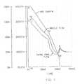
- FIG. 2is a graph illustrating an embodiment of a start up sequence according to the invention.
- FIG. 3is a graph illustrating an embodiment of a shut down sequence according to the invention.
- FIG. 1is a simplified schematic view of a conventional plasma arc torch, similar to the FL 100 plasma arc torch provided by InnerLogic, Inc. of Charleston, S.C. It should be appreciated, however, that the present inventive method is not limited to any particular type of plasma arc torch. Any manner of conventional torches may be modified by the inclusion of an aluminum sleeve which surrounds the cylindrical walls of the electrode element. When combined with the start up and shut down sequences of the present invention, greater electrode element life and operating efficiencies may be obtained.
- U.S. Pat. No. 5,070,227describes a control process applicable to a wide variety of torches, including torches sold by HyperTherm, Inc. of Hanover, N.H. The present control method is applicable to the types of torches described in the '227 patent upon modification of the electrode with the aluminum jacket as described below. The '227 patent is incorporated herein by reference in its entirety for all purposes.
- plasma arc torch 10has a basic body, generally indicated as 12 .
- Body 12includes a torch supply tube 34 defining a supply chamber 36 that is supplied with a source of pressurized ionizable gas from gas supply 24 through gas supply line 26 .
- Remotely actuated valves, such as solenoid valves 28 A, 28 B and 28 Care disposed in-line between supply tube 34 and gas source 24 to vary the supply of various gases to torch 10 upon actuation of the valve.
- Torch body 12includes an electrode body 46 , typically formed from copper.
- An electrode insert or element 50is fitted into the lower end of electrode body 46 .
- An aluminum sleeve 51forms a jacket around the cylindrical walls of element 50 .
- Element 50is typically formed of hafnium or zirconium, particularly when the plasma gas is a reactive gas.
- An insulating body 38generally surrounds the supply tube 34 and electrode body 46 .
- the cathode body 40is disposed generally surrounding supply tube 34 and an anode body 42 is disposed surrounding insulating body 38 .
- a nozzle 16is disposed at the forward end of electrode body 46 and defines an arc passageway 52 aligned with electrode element 50 .
- a swirl ring 44is disposed around the electrode body 46 and has holes defined therein to induce a swirling component to plasma gas entering the plasma gas chamber 14 , as will be discussed in greater detail below.
- a power supply 18is provided to supply electrical current to electrode body 46 and the electrode element 50 .
- a negative power lead 29is in electrical communication with supply tube 24 and cathode body 40 .
- a positive power lead 22is in electrical communication with anode body 42 through switch 23 .
- Insulating body 38electrically isolates anode body 42 from cathode body 40 .
- Positive power lead 22is also connectable to a work piece 54 that is to be cut or pierced by the plasma torch once switch 23 is opened.
- Power supply 18may constitute any conventional dc power supply sufficient to provide current to the torch at an appropriate voltage to initiate the pilot arc and then maintain the arc in the operational cutting mode of the torch.
- plasma gasflows from source 24 , through valves 28 B and 28 C, and enters supply line 26 , as generally indicated by the arrows in FIG. 1 .
- the plasma gasflows downward in chamber 36 through orifices in swirl ring 44 before entering the lower plasma gas chamber 14 .
- lower plasma gas chamber 14is in communication with the entirety of the supply chamber 36 of supply tube 34 so that a change in pressure anywhere within the system will affect a change in pressure within lower plasma gas chamber 14 .
- switch 23In the pilot arc mode of torch 10 , switch 23 is closed so that the positive lead is connected to anode body 42 .
- Power supply 20provides current at the appropriate voltage to initiate the pilot arc between electrode element 50 and nozzle 16 .
- a desired plasma gas flow and pressureare set by the operator for initiating the pilot arc.
- the pilot arcis started by a spark or other means, such as a contact starting technique, all of which are known in the art.
- the plasma gas flow during the pilot arc modeis from supply 24 , through valves 28 A, 28 B and 28 C, and through supply line 26 into supply chamber 34 , through the holes in swirl ring 44 , into lower plasma chamber 14 , and out through arc passageway 52 of nozzle 16 .
- the swirling flow generated by swirl ring 44is desired as a means for stabilizing the arc in all operational modes so that the arc does not impinge on and damage the nozzle.
- the torchIn order to transfer torch 10 to the cutting mode, the torch is brought close to workpiece 54 so that the arc transfers to the workpiece 54 as switch 23 opens.
- the transferred arcnow passes current from the electrode to workpiece 54 .
- the currentis increased to a desired level for cutting such that a plasma arc 56 is generated which extends through arc passageway 52 to workpiece 54 .
- the operational current levelsdepend on the type of torch and application desired, and typically range from about 20 to about 200 amps.
- the plasma gas within lower plasma chamber 14heats up and a decrease in plasma gas flow out of nozzle 16 results.
- pressure of the plasma gas being suppliedIn order to sustain sufficient plasma gas flow through nozzle 16 to sustain the plasma arc 56 , pressure of the plasma gas being supplied must be increased with the increase of current.
- the electrode lifeAs already described, a critical concern with conventional plasma arc torches is the electrode life, and particularly the life of the hafnium or zirconium inserts. It is known that the start up and shut down process results in severe wear of the electrode elements. The present Applicants have discovered that the electrode life can be substantially lengthened by following an improved start up sequence. Additionally, electrode life can be further lengthened by following an improved shut down sequence which substantially eliminates the oxidation of the electrode during a shut down mode. Further, the shut down protocol minimizes loss of the molten electrode insert material.
- the shut down mode of the present inventionsubstantially eliminates the formation of an oxide layer.
- the electrode lifewas about 300 to 600 pierces.
- the same model torchwas tested according to both the start up and shut down method of the present invention.
- the electrode lifewas extended to about 1,500 pierces. It is believed that this substantial increase in the electrode life was due to the chemical combination of aluminum, hafnium, and other element materials which may be present during the current reduction (insert cooling) that substantially eliminates oxide formation. Further, the loss of unsolidified electrode element's components which results from the post-flow of gases past the nozzle is further minimized by the present invention.
- FIG. 2represents a conceptual timing phase of one embodiment of a start up sequence according to the invention.
- the start up of the plasma arc torchinvolves the interaction of the plasma arc current, the plasma gas flow rate through the nozzle, and the gas pressure of the plasma gas within plasma gas chamber 14 , where chamber 14 is defined generally between the swirl ring 44 and the nozzle 16 .
- the left hand side of the graph of FIG. 2represents a start up sequence of the present invention.
- the end values on the far right hand side of the graph of FIG. 2represents the operational steady state values Io, Fo, and Po of the respective current and gas flow parameters.
- a pre-flow pressure sourceis provided through valve 28 A until time t3.
- valve 28 Bis turned on and immediately blocks the pre-flow gas from 28 A.
- the present inventionintroduces an increase in the arc current upslope rate from t4 to t5.
- the upslope increasecoincides with the increase beginning at t3 in the plasma gas flow rate through the nozzle.
- the increase in the arc current slope rate from t4 to t5in conjunction with a similar increase in the plasma gas flow rate through the nozzle, has been found to decrease erosion of the electrode during start up. When gas flow is too low relative to the current, nozzle damage may occur to the nozzle components. When gas flow is too high relative to the current, erosion of the electrode is increased.
- the arc currentis increasing between interval t2 to t5.
- the rate (slope) of the arc currentis further increased at t4.
- Increasing the arc currentis normally associated with a decrease in the nozzle flow as the arc current reduces the nozzle flow.
- This increase in the upslope rate of the arc currentoccurs immediately after the introduction at t3 of the operating nozzle flow and torch pressure.
- the upslope increase in arc currentbrings about a concomitant decrease in nozzle flow which would otherwise occur, thereby avoiding a nozzle flow gas overshoot.
- the current upslope rate increaseis timed in conjunction with the interval during which nozzle gas flow and pressure are also rapidly increasing. As the current increases, the rate of nozzle flow increase is regulated, decreasing damage to the electrode element.
- the value at interval t4 for the arc currentis 87 amps at 182 msec. It has been found in accordance with this invention that the sharp increase in arc current slope from t4 to t5 reduces damage to the torch during start up.
- the improvementrelates in part to the reduction in molten metal blowback during the piercing operation.
- the sharp current increase as reflected in the rate of risehas been found to more quickly penetrate the substrate and minimize damage of the torch components from the molten substrate.
- shut down sequencemakes use of the gas control components as seen and described in reference to FIG. 1 .
- gas control valve 28 Ais closed stopping the pre-flow gas and commencing plasma gas flow through valves 28 B (ports 1 and 2 ) and 28 C (ports 2 and 3 ) at a pressure of about 65 psi.
- a shut down sequenceis initiated at interval t0 which coincides with a de-energization of valve 28 B and thereby closes the respective port 1 .
- the de-energization of valve 28 Bthereby ceases the flow of plasma gas to the torch and results in an immediate decrease of pressure and flow rate through the nozzle as seen in reference to FIG. 3 .
- the arc currentis decreased from 200 amps to 115 amps, reducing by about four-fold the heat load on the electrode.
- the plasma arc diameterbegins to decrease, thereby exposing the molten electrode element material to the plasma gas.
- the aluminum jacketcan have a wall thickness of between 0.002 and 0.02 inches, and preferably about 0.004 inches.
- the aluminum jacket 51may actually melt and combine with the electrode element during operation of the torch.
- a hafnium electrodenormally has a uniform, dark gray coloration. Under operating conditions when oxides form, a white marbling effect occurs which is attributed to the formation of an oxide.
- the resulting electrode materialassumes a grayish color which is distinctive from the initial hafnium material and distinctly different in appearance from previously observed oxides.
- the electrode element/aluminum electrode combinationis still conductive and retains the useful properties of the hafnium and has the additional attributes of preventing the loss of efficiency associated with oxide formation on the electrode element. It is possible that the aluminum jacket eliminates the formation of oxidation products or, alternatively, the aluminum combines with the oxide to form yet another product which avoids the detrimental effects of the oxide. Irrespective of which, if any, of the above processes is occurring, the combination of the aluminum jacket with the electrode element achieves significant advantages in extending the electrode life.
- an improved electrode and electrode elementmay be provided for plasma arc torches.
- Such an electrodemay be provided by an alloy of aluminum and hafnium or an alloy of aluminum and zirconium.
- an electrode which comprises a molten mixture of aluminum and hafniumsimilar electrodes may be prepared and marketed for use in plasma arc torches.
- the relative amounts of aluminum or aluminum containing metals in combination with the zirconium or hafnium materialmay be readily determined by routine experimentation in which the resulting electrode life is monitored for various combinations of material.
- valve 28 Cis also energized which connects the pressurized post-flow, through orifice 53 of a flow restrictor 55 to the plasma torch inlet.
- the diameter or orifice 53should be selected in combination with the gas flow equipment and selected pressures so as to provide the desired post-flow pressure value.
- One having ordinary skill in the artis able to provide an appropriate flow restrictor and orifice therethrough so as to achieve the desired post-flow gas pressure needed for any individual torch.
- the post-flow pressureis maintained at a lesser pressure value than the plasma flow pressure.
- a post-flow operating pressureof about 6 pounds per square inch has been found useful. The 6 pounds of pressure is less than the pressure associated with the operating nozzle flow.
- the pressurized post-flowserves as a vent-like sink and helps maintain the correspondence between gas flow and arc current during the shut down sequence.
- the post-flow pressureis sufficiently greater than the plasma gas pressure such that the post-flow direction is now toward the rear of the torch and provides for nozzle flow rate of about 30% of the cutting flow rate at the time the arc current is shut off.
- the arc currentis shut off.
- the t2 intervalshould be selected at a point where the current is still sufficient to maintain a transferred arc.
- the swirl flowshould be high enough to maintain a stable arc while the nozzle pressure and post-flow pressures are sufficiently low to avoid a damaging level of gas flow overshoot when the arc is extinguished. It has been found useful to maintain a post-flow gas flow rate at interval t2 which is about 30% of the cutting plasma flow rate. As seen in reference to FIG. 2, the post-flow continues past interval t2 when the arc is extinguished. The resulting decrease in gas flow at the time the arc extinguishes has been found to greatly extend the electrode life.
- the gas flow apparatus and process set forth aboveprovides for a smooth transition of gas flow and gas pressures when the arc is extinguished.
- the gas flow apparatusserves as both a pressurized sink to reduce the torch plasma pressure and also provides a gas supply source prior to interval t2.
- the post-flow valveis actuated and pressure within the torch is allowed to equalize to the post-flow pressure. This results in the rapid decrease in the swirling and plasma flow gas pressures.
- the post-flowno longer operates as a sink but becomes a source, providing the swirl and post-flow pressures.
- the change over from a gas sink to a gas sourceoccurs about mid-way between intervals t1 and t2. The change over eliminates any pressure disturbances normally associated with a valve controlled gas flow.
- shut down protocol and sequencehas been found particularly useful for plasma arc torches operating at currents of 100 amps or greater.
- the present inventionhas been found to maintain a good correspondence between gas flow and arc current during both start up and shut down sequences.
- the formation of oxides on the electrodeis significantly reduced.
- the erosion of the electrode and the formation of oxides on the electrodeare reduced by maintaining an adequate swirling gas flow at the time current is cut off.
- the post-flow gas characteristicsare designed to prevent flow overshoot at current cut off, thereby minimizing damage to the electrode.
- the shut down protocolreduces the electrode temperature prior to arc current cut off, again minimizing the electrode erosion and electrode oxidation. Additional improvement is realized by use of the sink-source post-flow characteristics of the invention which minimizes the shut down processing time. By shortening the time required for the shut down protocol, erosion of the electrode element caused by premature arc current loss is eliminated.
- the present inventiondescribes a shut down protocol in which the current and the gas flow rate are sloped down in a continuous and corresponding manner. However, it is understood that similar improvements may be obtained by stepping down the current to a lower level such as 20 amps and running the torch for a brief interval while the torch cools down. Following cool down, the arc current may be shut off.
Landscapes
- Engineering & Computer Science (AREA)
- Physics & Mathematics (AREA)
- Plasma & Fusion (AREA)
- Spectroscopy & Molecular Physics (AREA)
- Mechanical Engineering (AREA)
- Plasma Technology (AREA)
Abstract
Description
Claims (17)
Priority Applications (1)
| Application Number | Priority Date | Filing Date | Title |
|---|---|---|---|
| US10/200,865US6677551B2 (en) | 1998-10-23 | 2002-07-23 | Process for operating a plasma arc torch |
Applications Claiming Priority (5)
| Application Number | Priority Date | Filing Date | Title |
|---|---|---|---|
| US09/178,206US6163009A (en) | 1998-10-23 | 1998-10-23 | Process for operating a plasma arc torch |
| US09/416,304US6093905A (en) | 1999-10-12 | 1999-10-12 | Process for operating a plasma arc torch |
| US09/540,077US6326583B1 (en) | 2000-03-31 | 2000-03-31 | Gas control system for a plasma arc torch |
| US09/824,177US6498317B2 (en) | 1998-10-23 | 2001-04-02 | Process for operating a plasma arc torch |
| US10/200,865US6677551B2 (en) | 1998-10-23 | 2002-07-23 | Process for operating a plasma arc torch |
Related Parent Applications (1)
| Application Number | Title | Priority Date | Filing Date |
|---|---|---|---|
| US09/824,177ContinuationUS6498317B2 (en) | 1998-10-23 | 2001-04-02 | Process for operating a plasma arc torch |
Publications (2)
| Publication Number | Publication Date |
|---|---|
| US20020185477A1 US20020185477A1 (en) | 2002-12-12 |
| US6677551B2true US6677551B2 (en) | 2004-01-13 |
Family
ID=27497274
Family Applications (1)
| Application Number | Title | Priority Date | Filing Date |
|---|---|---|---|
| US10/200,865Expired - Fee RelatedUS6677551B2 (en) | 1998-10-23 | 2002-07-23 | Process for operating a plasma arc torch |
Country Status (1)
| Country | Link |
|---|---|
| US (1) | US6677551B2 (en) |
Cited By (19)
| Publication number | Priority date | Publication date | Assignee | Title |
|---|---|---|---|---|
| US20050173381A1 (en)* | 2004-01-27 | 2005-08-11 | L'air Liquide, Societe Anonyme A Directoire Et Conseil De Surveillance Pour I'etude Et I'exploita | Plasma cutting process and unit with current slaved to the plasma gas |
| US20050258151A1 (en)* | 2004-05-18 | 2005-11-24 | The Esab Group, Inc. | Plasma arc torch |
| US20060151446A1 (en)* | 2005-01-03 | 2006-07-13 | Schneider Joseph C | Method and System of Conserving Plasma Torch Consumable |
| US20070045241A1 (en)* | 2005-08-29 | 2007-03-01 | Schneider Joseph C | Contact start plasma torch and method of operation |
| US20070235432A1 (en)* | 2006-03-30 | 2007-10-11 | Schneider Joseph C | Plasma torch with post flow control |
| US20110031224A1 (en)* | 2009-08-10 | 2011-02-10 | The Esab Group, Inc. | Retract start plasma torch with reversible coolant flow |
| US20120261392A1 (en)* | 2011-04-14 | 2012-10-18 | Thermal Dynamics Corporation | Method for starting a multi-gas plasma arc torch |
| US8395074B2 (en) | 2010-12-03 | 2013-03-12 | Kaliburn, Inc. | Plasma ARC systems with cutting and marking functions |
| US8981253B2 (en) | 2006-09-13 | 2015-03-17 | Hypertherm, Inc. | Forward flow, high access consumables for a plasma arc cutting torch |
| US9560732B2 (en) | 2006-09-13 | 2017-01-31 | Hypertherm, Inc. | High access consumables for a plasma arc cutting system |
| US20170095879A1 (en)* | 2015-10-06 | 2017-04-06 | Hypertherm, Inc. | Controlling Plasma Arc Torches and Related Systems and Methods |
| US9662747B2 (en) | 2006-09-13 | 2017-05-30 | Hypertherm, Inc. | Composite consumables for a plasma arc torch |
| US20170203381A1 (en)* | 2015-10-06 | 2017-07-20 | Hypertherm, Inc. | Controlling and Delivering Gases in a Plasma Arc Torch and Related Systems and Methods |
| USRE46925E1 (en) | 2001-03-09 | 2018-06-26 | Hypertherm, Inc. | Composite electrode for a plasma arc torch |
| US10098217B2 (en) | 2012-07-19 | 2018-10-09 | Hypertherm, Inc. | Composite consumables for a plasma arc torch |
| US10194516B2 (en) | 2006-09-13 | 2019-01-29 | Hypertherm, Inc. | High access consumables for a plasma arc cutting system |
| US10625359B2 (en) | 2018-04-06 | 2020-04-21 | The Esab Group Inc. | Automatic identification of components for welding and cutting torches |
| US11267069B2 (en) | 2018-04-06 | 2022-03-08 | The Esab Group Inc. | Recognition of components for welding and cutting torches |
| US11701734B2 (en) | 2019-07-25 | 2023-07-18 | The Esab Group, Inc. | Apparatus and methods associated with operating a plasma torch |
Families Citing this family (6)
| Publication number | Priority date | Publication date | Assignee | Title |
|---|---|---|---|---|
| US6805055B1 (en) | 2003-06-25 | 2004-10-19 | Gamma Recherches & Technologies Patent Sa | Plasma firing mechanism and method for firing ammunition |
| US7375303B2 (en)* | 2004-11-16 | 2008-05-20 | Hypertherm, Inc. | Plasma arc torch having an electrode with internal passages |
| JP2007275971A (en)* | 2006-04-11 | 2007-10-25 | Koike Sanso Kogyo Co Ltd | Plasma torch |
| FR2943568A1 (en)* | 2009-03-25 | 2010-10-01 | Air Liquide | Plasma cutting and fine cutting a metallic piece using torch supplied with gas and current, comprises progressively decreasing intensity of current, stopping supply of gas to torch, and evacuating towards outside of the gas supply line |
| FR2988975B1 (en)* | 2012-03-27 | 2014-05-09 | Air Liquide | METHOD FOR CONTROLLING THE EXTINGUISHING OF THE ELECTRIC ARC OF A ARC PLASMA TORCH |
| US9427820B2 (en)* | 2012-10-19 | 2016-08-30 | Hypertherm, Inc. | Thermal torch lead gas delivery methods and related systems and devices |
Citations (110)
| Publication number | Priority date | Publication date | Assignee | Title |
|---|---|---|---|---|
| US2906858A (en) | 1957-10-10 | 1959-09-29 | Union Carbide Corp | Liquid vortex arc torch process |
| US3082314A (en) | 1959-04-20 | 1963-03-19 | Shin Meiwa Kogyo Kabushiki Kai | Plasma arc torch |
| US3131288A (en) | 1961-08-07 | 1964-04-28 | Thermal Dynamics Corp | Electric arc torch |
| US3204076A (en) | 1962-10-04 | 1965-08-31 | Thermal Dynamics Corp | Electric arc torch |
| US3242305A (en) | 1963-07-03 | 1966-03-22 | Union Carbide Corp | Pressure retract arc torch |
| US3272962A (en) | 1965-05-03 | 1966-09-13 | Union Carbide Corp | Electric arc working process |
| US3373306A (en) | 1964-10-27 | 1968-03-12 | Northern Natural Gas Co | Method and apparatus for the control of ionization in a distributed electrical discharge |
| US3403211A (en) | 1965-03-31 | 1968-09-24 | Centre Nat Rech Scient | Methods and devices for heating substances |
| US3476906A (en) | 1966-11-21 | 1969-11-04 | United Aircraft Corp | Resistance monitoring apparatus |
| US3534388A (en) | 1968-03-13 | 1970-10-13 | Hitachi Ltd | Plasma jet cutting process |
| US3536885A (en) | 1965-10-25 | 1970-10-27 | Ass Elect Ind | Plasma torch assemblies |
| US3567898A (en) | 1968-07-01 | 1971-03-02 | Crucible Inc | Plasma arc cutting torch |
| US3575568A (en) | 1967-06-08 | 1971-04-20 | Rikagaku Kenkyusho | Arc torch |
| US3588594A (en) | 1968-01-19 | 1971-06-28 | Hitachi Ltd | Device for bending a plasma flame |
| US3601578A (en) | 1969-07-01 | 1971-08-24 | Siemens Ag | High-pressure plasma burner |
| US3619549A (en) | 1970-06-19 | 1971-11-09 | Union Carbide Corp | Arc torch cutting process |
| US3641308A (en) | 1970-06-29 | 1972-02-08 | Chemetron Corp | Plasma arc torch having liquid laminar flow jet for arc constriction |
| US3644782A (en) | 1969-12-24 | 1972-02-22 | Sheet Korman Associates Inc | Method of energy transfer utilizing a fluid convection cathode plasma jet |
| US3643580A (en) | 1969-12-01 | 1972-02-22 | Matthew Siegel | Fluid distribution apparatus preserving alignment of longitudinal axes of flow |
| FR2135469A1 (en) | 1971-05-06 | 1972-12-22 | Soudure Autogene Francaise | Plasma welding torch - with centring system for central electrode |
| US3770935A (en) | 1970-12-25 | 1973-11-06 | Rikagaku Kenkyusho | Plasma jet generator |
| US3787247A (en)* | 1972-04-06 | 1974-01-22 | Hypertherm Inc | Water-scrubber cutting table |
| US3833787A (en)* | 1972-06-12 | 1974-09-03 | Hypotherm Inc | Plasma jet cutting torch having reduced noise generating characteristics |
| JPS5082357A (en) | 1973-11-24 | 1975-07-03 | ||
| JPS50135721A (en) | 1974-04-03 | 1975-10-28 | ||
| US3930139A (en) | 1974-05-28 | 1975-12-30 | David Grigorievich Bykhovsky | Nonconsumable electrode for oxygen arc working |
| JPS5116379A (en) | 1974-07-31 | 1976-02-09 | Mitsubishi Heavy Ind Ltd | Haikibutsukara enkabinirukeijushio bunbetsukaishusuruhoho |
| JPS5121945A (en) | 1974-08-12 | 1976-02-21 | Ohara Minoru | Hakimonookoseisuru kakubuhinno yochakuhoho |
| US3949188A (en)* | 1973-07-20 | 1976-04-06 | Rikagaku Kenkyusho | Method and apparatus for operating an arc-transfer type torch |
| US3988566A (en)* | 1972-06-05 | 1976-10-26 | Metco Inc. | Automatic plasma flame spraying process and apparatus |
| JPS5236725A (en) | 1975-09-17 | 1977-03-22 | Matsushita Electric Industrial Co Ltd | Battery |
| US4029930A (en)* | 1972-09-04 | 1977-06-14 | Mitsubishi Jukogyo Kabushiki Kaisha | Welding torch for underwater welding |
| US4060088A (en)* | 1976-01-16 | 1977-11-29 | Valleylab, Inc. | Electrosurgical method and apparatus for establishing an electrical discharge in an inert gas flow |
| US4133987A (en)* | 1977-12-07 | 1979-01-09 | Institut Elektrosvarki Imeni E.O. Patona Adakemii Nauk | Electrode assembly for plasma arc torches |
| US4163891A (en)* | 1977-05-20 | 1979-08-07 | Origin Electric Co., Ltd. | Active gas plasma arc torch and a method of operating the same |
| US4174477A (en)* | 1973-04-09 | 1979-11-13 | U.S. Philips Corporation | Method of and device for arc welding |
| US4175225A (en) | 1977-09-19 | 1979-11-20 | General Atomic Company | Gas flow control circuit for plasma arc welding |
| US4195216A (en)* | 1977-03-18 | 1980-03-25 | Rolls-Royce Limited | Plasma welding |
| US4203022A (en)* | 1977-10-31 | 1980-05-13 | Hypertherm, Incorporated | Method and apparatus for positioning a plasma arc cutting torch |
| JPS55144337A (en) | 1979-04-27 | 1980-11-11 | Aida Eng Ltd | Connector of feed bar |
| US4275287A (en)* | 1978-09-28 | 1981-06-23 | Daidoto Kushuko Kabushikaisha | Plasma torch and a method of producing a plasma |
| US4282418A (en)* | 1978-09-11 | 1981-08-04 | Siemens Aktiengesellschaft | Plasma torch for micro-plasma welding |
| US4291217A (en)* | 1978-09-30 | 1981-09-22 | Messer Griesheim | Process for underwater plasma cutting of workpieces |
| JPS5768270A (en) | 1980-10-17 | 1982-04-26 | Hitachi Ltd | Control method for plasma cutting |
| US4341941A (en)* | 1979-03-01 | 1982-07-27 | Rikagaku Kenkyusho | Method of operating a plasma generating apparatus |
| JPS57165370A (en) | 1981-03-18 | 1982-10-12 | Ici Ltd | Triazole or imidazole compounds, manufacture and fungicidal or plant growth regulant agent |
| US4361748A (en)* | 1981-01-30 | 1982-11-30 | Couch Jr Richard W | Cooling and height sensing system for a plasma arc cutting tool |
| US4382170A (en)* | 1980-08-30 | 1983-05-03 | Trumpf Gmbh & Co. | Thermal cutting jet device with suction apparatus |
| US4389559A (en)* | 1981-01-28 | 1983-06-21 | Eutectic Corporation | Plasma-transferred-arc torch construction |
| US4410788A (en)* | 1980-04-16 | 1983-10-18 | Summers John E | Power and fluid supply source with multi-function cutting and welding capabilities |
| JPS58205676A (en) | 1982-05-26 | 1983-11-30 | Rikagaku Kenkyusho | Method for starting plasma torch equipped with cathode mantle |
| US4421970A (en)* | 1981-01-30 | 1983-12-20 | Hypertherm, Incorporated | Height sensing system for a plasma arc cutting tool |
| JPS59141371A (en) | 1983-01-31 | 1984-08-14 | Rikagaku Kenkyusho | How to start a plasma torch with a cathode jacket |
| US4506136A (en)* | 1982-10-12 | 1985-03-19 | Metco, Inc. | Plasma spray gun having a gas vortex producing nozzle |
| JPS6055221A (en) | 1983-09-06 | 1985-03-30 | Anritsu Corp | Running thickness gauge |
| US4521666A (en)* | 1982-12-23 | 1985-06-04 | Union Carbide Corporation | Plasma arc torch |
| US4567346A (en)* | 1983-12-07 | 1986-01-28 | L'air Liquide, Societe Anonyme Pour L'etude Et L'exploitation Des Procedes Georges Claude | Arc-striking method for a welding or cutting torch and a torch adapted to carry out said method |
| US4625094A (en)* | 1982-10-01 | 1986-11-25 | L'air Liquide, Societe Anonyme Pour L'etude Et L'exploitation Des Procedes Georges Claude | Plasma torches |
| JPS6228084A (en) | 1985-07-30 | 1987-02-06 | Akira Kanekawa | Plasma jet torch |
| US4645899A (en)* | 1984-09-28 | 1987-02-24 | Fried. Krupp Gesellschaft Mit Beschrankter Haftung | Plasma torch with hollow fluid cooled nozzle |
| US4647082A (en)* | 1986-03-17 | 1987-03-03 | Aeroquip Corporation | Releasable push-in connect fitting |
| US4663512A (en)* | 1985-11-04 | 1987-05-05 | Thermal Dynamics Corporation | Plasma-arc torch interlock with pressure sensing |
| US4692582A (en)* | 1985-02-22 | 1987-09-08 | L'air Liquide, Societe Anonyme Pour L'etude Et L'exploitation Des Procedes Georges Claude | Plasma welding or cutting system provided with a delay |
| US4701590A (en)* | 1986-04-17 | 1987-10-20 | Thermal Dynamics Corporation | Spring loaded electrode exposure interlock device |
| JPS6310082A (en) | 1986-06-27 | 1988-01-16 | ダブリユテイ−シ− ホ−ルデイングズ リミテツド | Torch for air plasma arc |
| JPS63101076A (en) | 1986-10-16 | 1988-05-06 | Mitsubishi Electric Corp | How to start the arc of a plasma arc welding machine |
| US4743734A (en)* | 1985-04-25 | 1988-05-10 | N P K Za Kontrolno Zavarachni Raboti | Nozzle for plasma arc torch |
| US4748312A (en)* | 1986-04-10 | 1988-05-31 | Thermal Dynamics Corporation | Plasma-arc torch with gas cooled blow-out electrode |
| JPS63180378A (en) | 1987-01-21 | 1988-07-25 | Matsushita Electric Ind Co Ltd | Torch for generating plasma jet |
| US4762977A (en)* | 1987-04-15 | 1988-08-09 | Browning James A | Double arc prevention for a transferred-arc flame spray system |
| US4764656A (en)* | 1987-05-15 | 1988-08-16 | Browning James A | Transferred-arc plasma apparatus and process with gas heating in excess of anode heating at the workpiece |
| US4782210A (en)* | 1987-06-26 | 1988-11-01 | Thermal Dynamics Corporation | Ridged electrode |
| US4791268A (en)* | 1987-01-30 | 1988-12-13 | Hypertherm, Inc. | Arc plasma torch and method using contact starting |
| WO1989000476A1 (en) | 1987-07-16 | 1989-01-26 | S P T Plasmateknik Aktiebolag | Burner for plasma cutting and welding |
| US4861962A (en)* | 1988-06-07 | 1989-08-29 | Hypertherm, Inc. | Nozzle shield for a plasma arc torch |
| US4866240A (en)* | 1988-09-08 | 1989-09-12 | Stoody Deloro Stellite, Inc. | Nozzle for plasma torch and method for introducing powder into the plasma plume of a plasma torch |
| US4882465A (en)* | 1987-10-01 | 1989-11-21 | Olin Corporation | Arcjet thruster with improved arc attachment for enhancement of efficiency |
| US4902871A (en) | 1987-01-30 | 1990-02-20 | Hypertherm, Inc. | Apparatus and process for cooling a plasma arc electrode |
| US4909914A (en) | 1985-05-11 | 1990-03-20 | Canon Kabushiki Kaisha | Reaction apparatus which introduces one reacting substance within a convergent-divergent nozzle |
| US4918283A (en) | 1986-08-13 | 1990-04-17 | Hitachi, Ltd. | Method of and apparatus for conducting plasma welding |
| WO1991002619A1 (en) | 1989-08-17 | 1991-03-07 | Hypertherm, Inc. | Plasma arc torch with improved nozzle shield and step flow |
| US5013885A (en) | 1990-02-28 | 1991-05-07 | Esab Welding Products, Inc. | Plasma arc torch having extended nozzle of substantially hourglass |
| US5017752A (en) | 1990-03-02 | 1991-05-21 | Esab Welding Products, Inc. | Plasma arc torch starting process having separated generated flows of non-oxidizing and oxidizing gas |
| US5023425A (en) | 1990-01-17 | 1991-06-11 | Esab Welding Products, Inc. | Electrode for plasma arc torch and method of fabricating same |
| US5070227A (en) | 1990-04-24 | 1991-12-03 | Hypertherm, Inc. | Proceses and apparatus for reducing electrode wear in a plasma arc torch |
| US5089221A (en) | 1990-10-25 | 1992-02-18 | General Electric Company | Composite spacer with Inconel grid and Zircaloy band |
| US5105061A (en) | 1991-02-15 | 1992-04-14 | The Lincoln Electric Company | Vented electrode for a plasma torch |
| US5132512A (en) | 1988-06-07 | 1992-07-21 | Hypertherm, Inc. | Arc torch nozzle shield for plasma |
| US5164568A (en) | 1989-10-20 | 1992-11-17 | Hypertherm, Inc. | Nozzle for a plasma arc torch having an angled inner surface to facilitate and control arc ignition |
| US5166494A (en) | 1990-04-24 | 1992-11-24 | Hypertherm, Inc. | Process and apparatus for reducing electrode wear in a plasma arc torch |
| JPH05104251A (en) | 1991-03-20 | 1993-04-27 | Komatsu Ltd | Plasma cutting machine and control method thereof |
| US5235162A (en) | 1992-05-26 | 1993-08-10 | Tescom Corporation | Plasma pilot arc ignition system |
| JPH05233025A (en) | 1992-02-19 | 1993-09-10 | Keyence Corp | Monitor information display device for programming console |
| US5290995A (en) | 1991-12-20 | 1994-03-01 | Esab Welding Products, Inc. | Plasma arc cutting system having fluid metering and power control systems |
| US5317126A (en) | 1992-01-14 | 1994-05-31 | Hypertherm, Inc. | Nozzle and method of operation for a plasma arc torch |
| US5393952A (en) | 1991-02-28 | 1995-02-28 | Kabushiki Kaisha Komatsu Seisakusho | Plasma torch for cutting use with nozzle protection cap having annular secondary GPS passage and insulator disposed in the secondary gas passage |
| US5396043A (en) | 1988-06-07 | 1995-03-07 | Hypertherm, Inc. | Plasma arc cutting process and apparatus using an oxygen-rich gas shield |
| US5414237A (en) | 1993-10-14 | 1995-05-09 | The Esab Group, Inc. | Plasma arc torch with integral gas exchange |
| US5468026A (en) | 1993-08-03 | 1995-11-21 | American Metal Products Company | Spacer clip for chimney |
| US5473140A (en) | 1994-03-14 | 1995-12-05 | Miller Electric Mfg. Co. | Welding nozzle retaining ring |
| US5506384A (en) | 1994-04-21 | 1996-04-09 | Kabushiki Kaisha Komatsu Seisakusho | Plasma arc cutting machine with variable constant current source and variable resistor |
| US5548097A (en) | 1993-03-30 | 1996-08-20 | Hypertherm, Inc. | Plasma arc cutting torch ignition circuit and method providing a forced arc transfer function |
| US5624586A (en) | 1995-01-04 | 1997-04-29 | Hypertherm, Inc. | Alignment device and method for a plasma arc torch system |
| US5653895A (en) | 1993-10-14 | 1997-08-05 | Komatsu Ltd. | Plasma cutting method suitable for cutting thin stainless steel sheet material |
| US5695662A (en) | 1988-06-07 | 1997-12-09 | Hypertherm, Inc. | Plasma arc cutting process and apparatus using an oxygen-rich gas shield |
| US5734144A (en) | 1993-03-26 | 1998-03-31 | Kabushiki Kaisha Komatsu Seisakusho | Plasma arc welding method and apparatus in which a swirling flow is imparted to a plasma gas to stabilize a plasma arc |
| US5841095A (en) | 1996-10-28 | 1998-11-24 | Hypertherm, Inc. | Apparatus and method for improved assembly concentricity in a plasma arc torch |
| US6028287A (en) | 1997-07-25 | 2000-02-22 | Hyperthem, Inc. | Plasma arc torch position control |
| US6054669A (en) | 1998-05-20 | 2000-04-25 | The Esab Group, Inc. | Plasma marking torch and method of operating same |
| US6093905A (en) | 1999-10-12 | 2000-07-25 | Innerlogic, Inc. | Process for operating a plasma arc torch |
- 2002
- 2002-07-23USUS10/200,865patent/US6677551B2/ennot_activeExpired - Fee Related
Patent Citations (115)
| Publication number | Priority date | Publication date | Assignee | Title |
|---|---|---|---|---|
| US2906858A (en) | 1957-10-10 | 1959-09-29 | Union Carbide Corp | Liquid vortex arc torch process |
| US3082314A (en) | 1959-04-20 | 1963-03-19 | Shin Meiwa Kogyo Kabushiki Kai | Plasma arc torch |
| US3131288A (en) | 1961-08-07 | 1964-04-28 | Thermal Dynamics Corp | Electric arc torch |
| US3204076A (en) | 1962-10-04 | 1965-08-31 | Thermal Dynamics Corp | Electric arc torch |
| US3242305A (en) | 1963-07-03 | 1966-03-22 | Union Carbide Corp | Pressure retract arc torch |
| US3373306A (en) | 1964-10-27 | 1968-03-12 | Northern Natural Gas Co | Method and apparatus for the control of ionization in a distributed electrical discharge |
| US3403211A (en) | 1965-03-31 | 1968-09-24 | Centre Nat Rech Scient | Methods and devices for heating substances |
| US3272962A (en) | 1965-05-03 | 1966-09-13 | Union Carbide Corp | Electric arc working process |
| US3536885A (en) | 1965-10-25 | 1970-10-27 | Ass Elect Ind | Plasma torch assemblies |
| US3476906A (en) | 1966-11-21 | 1969-11-04 | United Aircraft Corp | Resistance monitoring apparatus |
| US3575568A (en) | 1967-06-08 | 1971-04-20 | Rikagaku Kenkyusho | Arc torch |
| US3588594A (en) | 1968-01-19 | 1971-06-28 | Hitachi Ltd | Device for bending a plasma flame |
| US3534388A (en) | 1968-03-13 | 1970-10-13 | Hitachi Ltd | Plasma jet cutting process |
| US3567898A (en) | 1968-07-01 | 1971-03-02 | Crucible Inc | Plasma arc cutting torch |
| US3601578A (en) | 1969-07-01 | 1971-08-24 | Siemens Ag | High-pressure plasma burner |
| US3643580A (en) | 1969-12-01 | 1972-02-22 | Matthew Siegel | Fluid distribution apparatus preserving alignment of longitudinal axes of flow |
| US3644782A (en) | 1969-12-24 | 1972-02-22 | Sheet Korman Associates Inc | Method of energy transfer utilizing a fluid convection cathode plasma jet |
| US3619549A (en) | 1970-06-19 | 1971-11-09 | Union Carbide Corp | Arc torch cutting process |
| US3641308A (en) | 1970-06-29 | 1972-02-08 | Chemetron Corp | Plasma arc torch having liquid laminar flow jet for arc constriction |
| US3770935A (en) | 1970-12-25 | 1973-11-06 | Rikagaku Kenkyusho | Plasma jet generator |
| FR2135469A1 (en) | 1971-05-06 | 1972-12-22 | Soudure Autogene Francaise | Plasma welding torch - with centring system for central electrode |
| US3787247A (en)* | 1972-04-06 | 1974-01-22 | Hypertherm Inc | Water-scrubber cutting table |
| US3988566A (en)* | 1972-06-05 | 1976-10-26 | Metco Inc. | Automatic plasma flame spraying process and apparatus |
| US3833787A (en)* | 1972-06-12 | 1974-09-03 | Hypotherm Inc | Plasma jet cutting torch having reduced noise generating characteristics |
| US4029930A (en)* | 1972-09-04 | 1977-06-14 | Mitsubishi Jukogyo Kabushiki Kaisha | Welding torch for underwater welding |
| US4174477A (en)* | 1973-04-09 | 1979-11-13 | U.S. Philips Corporation | Method of and device for arc welding |
| US3949188A (en)* | 1973-07-20 | 1976-04-06 | Rikagaku Kenkyusho | Method and apparatus for operating an arc-transfer type torch |
| JPS5082357A (en) | 1973-11-24 | 1975-07-03 | ||
| JPS50135721A (en) | 1974-04-03 | 1975-10-28 | ||
| US3930139A (en) | 1974-05-28 | 1975-12-30 | David Grigorievich Bykhovsky | Nonconsumable electrode for oxygen arc working |
| JPS5116379A (en) | 1974-07-31 | 1976-02-09 | Mitsubishi Heavy Ind Ltd | Haikibutsukara enkabinirukeijushio bunbetsukaishusuruhoho |
| JPS5121945A (en) | 1974-08-12 | 1976-02-21 | Ohara Minoru | Hakimonookoseisuru kakubuhinno yochakuhoho |
| JPS5236725A (en) | 1975-09-17 | 1977-03-22 | Matsushita Electric Industrial Co Ltd | Battery |
| US4060088A (en)* | 1976-01-16 | 1977-11-29 | Valleylab, Inc. | Electrosurgical method and apparatus for establishing an electrical discharge in an inert gas flow |
| US4195216A (en)* | 1977-03-18 | 1980-03-25 | Rolls-Royce Limited | Plasma welding |
| US4163891A (en)* | 1977-05-20 | 1979-08-07 | Origin Electric Co., Ltd. | Active gas plasma arc torch and a method of operating the same |
| US4175225A (en) | 1977-09-19 | 1979-11-20 | General Atomic Company | Gas flow control circuit for plasma arc welding |
| US4203022A (en)* | 1977-10-31 | 1980-05-13 | Hypertherm, Incorporated | Method and apparatus for positioning a plasma arc cutting torch |
| US4133987A (en)* | 1977-12-07 | 1979-01-09 | Institut Elektrosvarki Imeni E.O. Patona Adakemii Nauk | Electrode assembly for plasma arc torches |
| US4282418A (en)* | 1978-09-11 | 1981-08-04 | Siemens Aktiengesellschaft | Plasma torch for micro-plasma welding |
| US4275287A (en)* | 1978-09-28 | 1981-06-23 | Daidoto Kushuko Kabushikaisha | Plasma torch and a method of producing a plasma |
| US4291217A (en)* | 1978-09-30 | 1981-09-22 | Messer Griesheim | Process for underwater plasma cutting of workpieces |
| US4341941A (en)* | 1979-03-01 | 1982-07-27 | Rikagaku Kenkyusho | Method of operating a plasma generating apparatus |
| JPS55144337A (en) | 1979-04-27 | 1980-11-11 | Aida Eng Ltd | Connector of feed bar |
| US4410788A (en)* | 1980-04-16 | 1983-10-18 | Summers John E | Power and fluid supply source with multi-function cutting and welding capabilities |
| US4382170A (en)* | 1980-08-30 | 1983-05-03 | Trumpf Gmbh & Co. | Thermal cutting jet device with suction apparatus |
| JPS5768270A (en) | 1980-10-17 | 1982-04-26 | Hitachi Ltd | Control method for plasma cutting |
| US4389559A (en)* | 1981-01-28 | 1983-06-21 | Eutectic Corporation | Plasma-transferred-arc torch construction |
| US4361748A (en)* | 1981-01-30 | 1982-11-30 | Couch Jr Richard W | Cooling and height sensing system for a plasma arc cutting tool |
| US4421970A (en)* | 1981-01-30 | 1983-12-20 | Hypertherm, Incorporated | Height sensing system for a plasma arc cutting tool |
| JPS57165370A (en) | 1981-03-18 | 1982-10-12 | Ici Ltd | Triazole or imidazole compounds, manufacture and fungicidal or plant growth regulant agent |
| JPS58205676A (en) | 1982-05-26 | 1983-11-30 | Rikagaku Kenkyusho | Method for starting plasma torch equipped with cathode mantle |
| US4625094A (en)* | 1982-10-01 | 1986-11-25 | L'air Liquide, Societe Anonyme Pour L'etude Et L'exploitation Des Procedes Georges Claude | Plasma torches |
| US4506136A (en)* | 1982-10-12 | 1985-03-19 | Metco, Inc. | Plasma spray gun having a gas vortex producing nozzle |
| US4521666A (en)* | 1982-12-23 | 1985-06-04 | Union Carbide Corporation | Plasma arc torch |
| JPS59141371A (en) | 1983-01-31 | 1984-08-14 | Rikagaku Kenkyusho | How to start a plasma torch with a cathode jacket |
| JPS6055221A (en) | 1983-09-06 | 1985-03-30 | Anritsu Corp | Running thickness gauge |
| US4567346A (en)* | 1983-12-07 | 1986-01-28 | L'air Liquide, Societe Anonyme Pour L'etude Et L'exploitation Des Procedes Georges Claude | Arc-striking method for a welding or cutting torch and a torch adapted to carry out said method |
| US4645899A (en)* | 1984-09-28 | 1987-02-24 | Fried. Krupp Gesellschaft Mit Beschrankter Haftung | Plasma torch with hollow fluid cooled nozzle |
| US4692582A (en)* | 1985-02-22 | 1987-09-08 | L'air Liquide, Societe Anonyme Pour L'etude Et L'exploitation Des Procedes Georges Claude | Plasma welding or cutting system provided with a delay |
| US4743734A (en)* | 1985-04-25 | 1988-05-10 | N P K Za Kontrolno Zavarachni Raboti | Nozzle for plasma arc torch |
| US4909914A (en) | 1985-05-11 | 1990-03-20 | Canon Kabushiki Kaisha | Reaction apparatus which introduces one reacting substance within a convergent-divergent nozzle |
| JPS6228084A (en) | 1985-07-30 | 1987-02-06 | Akira Kanekawa | Plasma jet torch |
| US4663512A (en)* | 1985-11-04 | 1987-05-05 | Thermal Dynamics Corporation | Plasma-arc torch interlock with pressure sensing |
| US4647082A (en)* | 1986-03-17 | 1987-03-03 | Aeroquip Corporation | Releasable push-in connect fitting |
| US4748312A (en)* | 1986-04-10 | 1988-05-31 | Thermal Dynamics Corporation | Plasma-arc torch with gas cooled blow-out electrode |
| US4701590A (en)* | 1986-04-17 | 1987-10-20 | Thermal Dynamics Corporation | Spring loaded electrode exposure interlock device |
| JPS6310082A (en) | 1986-06-27 | 1988-01-16 | ダブリユテイ−シ− ホ−ルデイングズ リミテツド | Torch for air plasma arc |
| US4918283A (en) | 1986-08-13 | 1990-04-17 | Hitachi, Ltd. | Method of and apparatus for conducting plasma welding |
| JPS63101076A (en) | 1986-10-16 | 1988-05-06 | Mitsubishi Electric Corp | How to start the arc of a plasma arc welding machine |
| JPS63180378A (en) | 1987-01-21 | 1988-07-25 | Matsushita Electric Ind Co Ltd | Torch for generating plasma jet |
| US4791268A (en)* | 1987-01-30 | 1988-12-13 | Hypertherm, Inc. | Arc plasma torch and method using contact starting |
| US4902871A (en) | 1987-01-30 | 1990-02-20 | Hypertherm, Inc. | Apparatus and process for cooling a plasma arc electrode |
| US4762977A (en)* | 1987-04-15 | 1988-08-09 | Browning James A | Double arc prevention for a transferred-arc flame spray system |
| US4764656A (en)* | 1987-05-15 | 1988-08-16 | Browning James A | Transferred-arc plasma apparatus and process with gas heating in excess of anode heating at the workpiece |
| US4782210A (en)* | 1987-06-26 | 1988-11-01 | Thermal Dynamics Corporation | Ridged electrode |
| WO1989000476A1 (en) | 1987-07-16 | 1989-01-26 | S P T Plasmateknik Aktiebolag | Burner for plasma cutting and welding |
| US4882465A (en)* | 1987-10-01 | 1989-11-21 | Olin Corporation | Arcjet thruster with improved arc attachment for enhancement of efficiency |
| US5120930A (en) | 1988-06-07 | 1992-06-09 | Hypertherm, Inc. | Plasma arc torch with improved nozzle shield and step flow |
| US4861962A (en)* | 1988-06-07 | 1989-08-29 | Hypertherm, Inc. | Nozzle shield for a plasma arc torch |
| US4861962B1 (en)* | 1988-06-07 | 1996-07-16 | Hypertherm Inc | Nozzle shield for a plasma arc torch |
| US5591357A (en) | 1988-06-07 | 1997-01-07 | Hypertherm, Inc. | Plasma arc cutting process and apparatus using an oxygen-rich gas shield |
| US5132512A (en) | 1988-06-07 | 1992-07-21 | Hypertherm, Inc. | Arc torch nozzle shield for plasma |
| US5396043A (en) | 1988-06-07 | 1995-03-07 | Hypertherm, Inc. | Plasma arc cutting process and apparatus using an oxygen-rich gas shield |
| US5695662A (en) | 1988-06-07 | 1997-12-09 | Hypertherm, Inc. | Plasma arc cutting process and apparatus using an oxygen-rich gas shield |
| US4866240A (en)* | 1988-09-08 | 1989-09-12 | Stoody Deloro Stellite, Inc. | Nozzle for plasma torch and method for introducing powder into the plasma plume of a plasma torch |
| WO1991002619A1 (en) | 1989-08-17 | 1991-03-07 | Hypertherm, Inc. | Plasma arc torch with improved nozzle shield and step flow |
| US5164568A (en) | 1989-10-20 | 1992-11-17 | Hypertherm, Inc. | Nozzle for a plasma arc torch having an angled inner surface to facilitate and control arc ignition |
| US5023425A (en) | 1990-01-17 | 1991-06-11 | Esab Welding Products, Inc. | Electrode for plasma arc torch and method of fabricating same |
| US5013885A (en) | 1990-02-28 | 1991-05-07 | Esab Welding Products, Inc. | Plasma arc torch having extended nozzle of substantially hourglass |
| US5017752A (en) | 1990-03-02 | 1991-05-21 | Esab Welding Products, Inc. | Plasma arc torch starting process having separated generated flows of non-oxidizing and oxidizing gas |
| US5070227A (en) | 1990-04-24 | 1991-12-03 | Hypertherm, Inc. | Proceses and apparatus for reducing electrode wear in a plasma arc torch |
| US5166494A (en) | 1990-04-24 | 1992-11-24 | Hypertherm, Inc. | Process and apparatus for reducing electrode wear in a plasma arc torch |
| US5170033A (en) | 1990-04-24 | 1992-12-08 | Hypertherm, Inc. | Swirl ring and flow control process for a plasma arc torch |
| US5089221A (en) | 1990-10-25 | 1992-02-18 | General Electric Company | Composite spacer with Inconel grid and Zircaloy band |
| US5105061A (en) | 1991-02-15 | 1992-04-14 | The Lincoln Electric Company | Vented electrode for a plasma torch |
| US5393952A (en) | 1991-02-28 | 1995-02-28 | Kabushiki Kaisha Komatsu Seisakusho | Plasma torch for cutting use with nozzle protection cap having annular secondary GPS passage and insulator disposed in the secondary gas passage |
| US5424507A (en) | 1991-03-20 | 1995-06-13 | Kabushiki Kaisha Komatsu Seisakusho | Controlling working gas flow rate and arc current level in plasma arc cutting machine |
| JPH05104251A (en) | 1991-03-20 | 1993-04-27 | Komatsu Ltd | Plasma cutting machine and control method thereof |
| US5290995A (en) | 1991-12-20 | 1994-03-01 | Esab Welding Products, Inc. | Plasma arc cutting system having fluid metering and power control systems |
| US5317126A (en) | 1992-01-14 | 1994-05-31 | Hypertherm, Inc. | Nozzle and method of operation for a plasma arc torch |
| JPH05233025A (en) | 1992-02-19 | 1993-09-10 | Keyence Corp | Monitor information display device for programming console |
| US5235162A (en) | 1992-05-26 | 1993-08-10 | Tescom Corporation | Plasma pilot arc ignition system |
| US5734144A (en) | 1993-03-26 | 1998-03-31 | Kabushiki Kaisha Komatsu Seisakusho | Plasma arc welding method and apparatus in which a swirling flow is imparted to a plasma gas to stabilize a plasma arc |
| US5548097A (en) | 1993-03-30 | 1996-08-20 | Hypertherm, Inc. | Plasma arc cutting torch ignition circuit and method providing a forced arc transfer function |
| US5468026A (en) | 1993-08-03 | 1995-11-21 | American Metal Products Company | Spacer clip for chimney |
| US5653895A (en) | 1993-10-14 | 1997-08-05 | Komatsu Ltd. | Plasma cutting method suitable for cutting thin stainless steel sheet material |
| US5414237A (en) | 1993-10-14 | 1995-05-09 | The Esab Group, Inc. | Plasma arc torch with integral gas exchange |
| US5473140A (en) | 1994-03-14 | 1995-12-05 | Miller Electric Mfg. Co. | Welding nozzle retaining ring |
| US5506384A (en) | 1994-04-21 | 1996-04-09 | Kabushiki Kaisha Komatsu Seisakusho | Plasma arc cutting machine with variable constant current source and variable resistor |
| US5624586A (en) | 1995-01-04 | 1997-04-29 | Hypertherm, Inc. | Alignment device and method for a plasma arc torch system |
| US5841095A (en) | 1996-10-28 | 1998-11-24 | Hypertherm, Inc. | Apparatus and method for improved assembly concentricity in a plasma arc torch |
| US6028287A (en) | 1997-07-25 | 2000-02-22 | Hyperthem, Inc. | Plasma arc torch position control |
| US6054669A (en) | 1998-05-20 | 2000-04-25 | The Esab Group, Inc. | Plasma marking torch and method of operating same |
| US6093905A (en) | 1999-10-12 | 2000-07-25 | Innerlogic, Inc. | Process for operating a plasma arc torch |
Cited By (33)
| Publication number | Priority date | Publication date | Assignee | Title |
|---|---|---|---|---|
| USRE46925E1 (en) | 2001-03-09 | 2018-06-26 | Hypertherm, Inc. | Composite electrode for a plasma arc torch |
| US20050173381A1 (en)* | 2004-01-27 | 2005-08-11 | L'air Liquide, Societe Anonyme A Directoire Et Conseil De Surveillance Pour I'etude Et I'exploita | Plasma cutting process and unit with current slaved to the plasma gas |
| US20050258151A1 (en)* | 2004-05-18 | 2005-11-24 | The Esab Group, Inc. | Plasma arc torch |
| US6969819B1 (en)* | 2004-05-18 | 2005-11-29 | The Esab Group, Inc. | Plasma arc torch |
| US20060151446A1 (en)* | 2005-01-03 | 2006-07-13 | Schneider Joseph C | Method and System of Conserving Plasma Torch Consumable |
| US7807937B2 (en)* | 2005-01-03 | 2010-10-05 | Illinois Tool Works Inc. | Method and system of conserving plasma torch consumable |
| US20070045241A1 (en)* | 2005-08-29 | 2007-03-01 | Schneider Joseph C | Contact start plasma torch and method of operation |
| US20070235432A1 (en)* | 2006-03-30 | 2007-10-11 | Schneider Joseph C | Plasma torch with post flow control |
| US7781699B2 (en) | 2006-03-30 | 2010-08-24 | Illinois Tool Works Inc. | Plasma torch with post flow control |
| US9560732B2 (en) | 2006-09-13 | 2017-01-31 | Hypertherm, Inc. | High access consumables for a plasma arc cutting system |
| US8981253B2 (en) | 2006-09-13 | 2015-03-17 | Hypertherm, Inc. | Forward flow, high access consumables for a plasma arc cutting torch |
| US9662747B2 (en) | 2006-09-13 | 2017-05-30 | Hypertherm, Inc. | Composite consumables for a plasma arc torch |
| US10194516B2 (en) | 2006-09-13 | 2019-01-29 | Hypertherm, Inc. | High access consumables for a plasma arc cutting system |
| US8633414B2 (en) | 2009-08-10 | 2014-01-21 | The Esab Group, Inc. | Retract start plasma torch with reversible coolant flow |
| US8258423B2 (en) | 2009-08-10 | 2012-09-04 | The Esab Group, Inc. | Retract start plasma torch with reversible coolant flow |
| US20110031224A1 (en)* | 2009-08-10 | 2011-02-10 | The Esab Group, Inc. | Retract start plasma torch with reversible coolant flow |
| US8395074B2 (en) | 2010-12-03 | 2013-03-12 | Kaliburn, Inc. | Plasma ARC systems with cutting and marking functions |
| US20120261392A1 (en)* | 2011-04-14 | 2012-10-18 | Thermal Dynamics Corporation | Method for starting a multi-gas plasma arc torch |
| US9024230B2 (en)* | 2011-04-14 | 2015-05-05 | Victor Equipment Company | Method for starting a multi-gas plasma arc torch |
| US10098217B2 (en) | 2012-07-19 | 2018-10-09 | Hypertherm, Inc. | Composite consumables for a plasma arc torch |
| US20170095879A1 (en)* | 2015-10-06 | 2017-04-06 | Hypertherm, Inc. | Controlling Plasma Arc Torches and Related Systems and Methods |
| US20170203381A1 (en)* | 2015-10-06 | 2017-07-20 | Hypertherm, Inc. | Controlling and Delivering Gases in a Plasma Arc Torch and Related Systems and Methods |
| US10279417B2 (en)* | 2015-10-06 | 2019-05-07 | Hypertherm, Inc. | Controlling and delivering gases in a plasma arc torch and related systems and methods |
| US10562125B2 (en) | 2015-10-06 | 2020-02-18 | Hypertherm, Inc. | Controlling plasma arc torches and related systems and methods |
| US10722971B2 (en)* | 2015-10-06 | 2020-07-28 | Hypertherm, Inc. | Controlling plasma arc torches and related systems and methods |
| US10722970B2 (en) | 2015-10-06 | 2020-07-28 | Hypertherm, Inc. | Controlling plasma arc torches and related systems and methods |
| US11040412B2 (en) | 2015-10-06 | 2021-06-22 | Hypertherm, Inc. | Controlling and delivering gases in a plasma arc torch and related systems and methods |
| US11826847B2 (en) | 2015-10-06 | 2023-11-28 | Hypertherm, Inc. | Controlling plasma arc torches and related systems and methods |
| US12325082B2 (en)* | 2015-10-06 | 2025-06-10 | Hypertherm, Inc. | Controlling and delivering gases in a plasma arc torch and related systems and methods |
| US10625359B2 (en) | 2018-04-06 | 2020-04-21 | The Esab Group Inc. | Automatic identification of components for welding and cutting torches |
| US11267069B2 (en) | 2018-04-06 | 2022-03-08 | The Esab Group Inc. | Recognition of components for welding and cutting torches |
| US11883896B2 (en) | 2018-04-06 | 2024-01-30 | The Esab Group, Inc. | Recognition of components for welding and cutting torches |
| US11701734B2 (en) | 2019-07-25 | 2023-07-18 | The Esab Group, Inc. | Apparatus and methods associated with operating a plasma torch |
Also Published As
| Publication number | Publication date |
|---|---|
| US20020185477A1 (en) | 2002-12-12 |
Similar Documents
| Publication | Publication Date | Title |
|---|---|---|
| US6677551B2 (en) | Process for operating a plasma arc torch | |
| US6498317B2 (en) | Process for operating a plasma arc torch | |
| US5166494A (en) | Process and apparatus for reducing electrode wear in a plasma arc torch | |
| JP3100157B2 (en) | Method and apparatus for reducing electrode wear in a plasma arc torch | |
| CA2133498C (en) | Plasma arc torch with integral gas exchange | |
| US6248972B1 (en) | Plasma cutting method, device and gas supply system for plasma cutting torch | |
| JP3783014B2 (en) | Plasma arc torch and method of operating the same | |
| US20040211760A1 (en) | Plasma cutting process with dual gas flow | |
| US5801355A (en) | Plasma piercing with non-oxidative plasma gas and plasma cutting with oxidative plasma gas | |
| US6163009A (en) | Process for operating a plasma arc torch | |
| KR100272917B1 (en) | Plasma cutting method | |
| CA2330069C (en) | Method and apparatus for improving plasma arc consumable life | |
| US6093905A (en) | Process for operating a plasma arc torch | |
| JP2950986B2 (en) | Vortex ring and flow control method for plasma arc torch | |
| KR100960845B1 (en) | Plasma cutting device and method | |
| US6933463B2 (en) | Main arc ignition device and main arc ignition control method of plasma cutting machine | |
| US6069336A (en) | Plasma or TIG welding or cutting process with a non-oxidizing gas having a low H2 O and/or O2 impurity content | |
| EP1131181B1 (en) | Improved welding apparatus and method | |
| US6686557B1 (en) | Nonflammable ternary gas mix for high pressure plasmas | |
| Carlson et al. | High definition single-wire-arc-spray | |
| JPH11192558A (en) | Plasma cutting method and plasma cutting device | |
| JPH06328258A (en) | Plasma cutting method and cutting device | |
| WO1996025265A1 (en) | Plasma cutting method |
Legal Events
| Date | Code | Title | Description |
|---|---|---|---|
| AS | Assignment | Owner name:HARDWICK, STEVEN F., SOUTH CAROLINA Free format text:ASSIGNMENT OF ASSIGNORS INTEREST;ASSIGNOR:KALIBURN, INC. F/K/A INNERLOGIC, INC.;REEL/FRAME:018490/0776 Effective date:20060825 | |
| AS | Assignment | Owner name:RAYZR, LLC, SOUTH CAROLINA Free format text:ASSIGNMENT OF ASSIGNORS INTEREST;ASSIGNOR:HARDWICK, STEVEN F.;REEL/FRAME:018420/0181 Effective date:20061011 | |
| FPAY | Fee payment | Year of fee payment:4 | |
| FEPP | Fee payment procedure | Free format text:PAYOR NUMBER ASSIGNED (ORIGINAL EVENT CODE: ASPN); ENTITY STATUS OF PATENT OWNER: LARGE ENTITY | |
| AS | Assignment | Owner name:KALIBURN, INC., SOUTH CAROLINA Free format text:CHANGE OF NAME;ASSIGNOR:INNERLOGIC, INC.;REEL/FRAME:020403/0855 Effective date:20060620 | |
| AS | Assignment | Owner name:KALIBURN, INC., SOUTH CAROLINA Free format text:ASSIGNMENT OF ASSIGNORS INTEREST;ASSIGNOR:RAYZR, LLC;REEL/FRAME:020741/0536 Effective date:20080403 | |
| FPAY | Fee payment | Year of fee payment:8 | |
| FEPP | Fee payment procedure | Free format text:PAT HOLDER NO LONGER CLAIMS SMALL ENTITY STATUS, ENTITY STATUS SET TO UNDISCOUNTED (ORIGINAL EVENT CODE: STOL); ENTITY STATUS OF PATENT OWNER: LARGE ENTITY | |
| AS | Assignment | Owner name:LINCOLN GLOBAL, INC., CALIFORNIA Free format text:ASSIGNMENT OF ASSIGNORS INTEREST;ASSIGNOR:KALIBURN, INC.;REEL/FRAME:031432/0581 Effective date:20130919 | |
| REMI | Maintenance fee reminder mailed | ||
| LAPS | Lapse for failure to pay maintenance fees | ||
| STCH | Information on status: patent discontinuation | Free format text:PATENT EXPIRED DUE TO NONPAYMENT OF MAINTENANCE FEES UNDER 37 CFR 1.362 | |
| FP | Lapsed due to failure to pay maintenance fee | Effective date:20160113 |