US6677520B1 - Fanning tray - Google Patents
Fanning trayDownload PDFInfo
- Publication number
- US6677520B1 US6677520B1US10/201,623US20162302AUS6677520B1US 6677520 B1US6677520 B1US 6677520B1US 20162302 AUS20162302 AUS 20162302AUS 6677520 B1US6677520 B1US 6677520B1
- Authority
- US
- United States
- Prior art keywords
- cable
- drawer
- tray
- fanning
- cables
- Prior art date
- Legal status (The legal status is an assumption and is not a legal conclusion. Google has not performed a legal analysis and makes no representation as to the accuracy of the status listed.)
- Expired - Lifetime
Links
Images


Classifications
- H—ELECTRICITY
- H02—GENERATION; CONVERSION OR DISTRIBUTION OF ELECTRIC POWER
- H02G—INSTALLATION OF ELECTRIC CABLES OR LINES, OR OF COMBINED OPTICAL AND ELECTRIC CABLES OR LINES
- H02G3/00—Installations of electric cables or lines or protective tubing therefor in or on buildings, equivalent structures or vehicles
- H02G3/02—Details
- H02G3/04—Protective tubing or conduits, e.g. cable ladders or cable troughs
- H02G3/0437—Channels
- G—PHYSICS
- G02—OPTICS
- G02B—OPTICAL ELEMENTS, SYSTEMS OR APPARATUS
- G02B6/00—Light guides; Structural details of arrangements comprising light guides and other optical elements, e.g. couplings
- G02B6/44—Mechanical structures for providing tensile strength and external protection for fibres, e.g. optical transmission cables
- G02B6/4439—Auxiliary devices
- G02B6/444—Systems or boxes with surplus lengths
- G02B6/4453—Cassettes
- H—ELECTRICITY
- H05—ELECTRIC TECHNIQUES NOT OTHERWISE PROVIDED FOR
- H05K—PRINTED CIRCUITS; CASINGS OR CONSTRUCTIONAL DETAILS OF ELECTRIC APPARATUS; MANUFACTURE OF ASSEMBLAGES OF ELECTRICAL COMPONENTS
- H05K7/00—Constructional details common to different types of electric apparatus
- H05K7/18—Construction of rack or frame
- H05K7/186—Construction of rack or frame for supporting telecommunication equipment
- Y—GENERAL TAGGING OF NEW TECHNOLOGICAL DEVELOPMENTS; GENERAL TAGGING OF CROSS-SECTIONAL TECHNOLOGIES SPANNING OVER SEVERAL SECTIONS OF THE IPC; TECHNICAL SUBJECTS COVERED BY FORMER USPC CROSS-REFERENCE ART COLLECTIONS [XRACs] AND DIGESTS
- Y10—TECHNICAL SUBJECTS COVERED BY FORMER USPC
- Y10S—TECHNICAL SUBJECTS COVERED BY FORMER USPC CROSS-REFERENCE ART COLLECTIONS [XRACs] AND DIGESTS
- Y10S439/00—Electrical connectors
- Y10S439/944—Coaxial connector having circuit-interrupting provision effected by mating or having "dead" contact activated after mating
Definitions
- the present inventionrelates to cable management devices and methods for telecommunications cables.
- the present inventionconcerns cable management devices and methods.
- the devicesare mounted to a rack for managing cables extending to and from equipment on the rack.
- Equipmentis mounted to the rack and extends across the width of the rack. Cables from the equipment extend vertically downwardly in one preferred embodiment.
- a fanning traydirects the vertical cables to one or more vertical cable guides.
- the rackincludes cable slack management devices.
- the rackalso includes termination locations for terminating the cables and for connecting the cables to other cables. In one preferred embodiment, cable slack storage locations and the termination locations are located in slideable drawers.
- the present inventionrelates to an optical fiber cable management panel including a drawer assembly including a chassis and a drawer wherein the drawer is slidably mounted within the chassis.
- the drawer assemblydefines a storage interior and a first cable access entry to permit optical fiber cable to enter into the storage interior.
- a cable radius limiteris slidably mounted relative to the drawer assembly.
- a releasable lockallows selective release of the cable radius limiter for releasing slack at a desired time.
- the preferred drawer assemblycan be mounted to a rack with other drawers or other equipment.
- the preferred drawer assemblyalso includes a second cable radius limiter which moves in a synchronized manner with the drawer to manage cables at the first cable access entry point.
- the present inventionalso relates to an optical fiber cable management panel including a drawer assembly including a chassis and a drawer wherein the drawer is slidably mounted within the chassis.
- the drawer assemblydefines a storage interior and a first cable access entry to permit optical fiber cable to enter into the storage interior.
- a slidable termination panelis positioned within the storage interior. This slidable panel slides vertically when the drawer is positioned out of the chassis.
- Slidable mountsmount the panel and include two slide mechanisms on opposite ends of the panel.
- the preferred mountsinclude locks for retaining the panel in the closed, or down position.
- the preferred drawer assemblycan be mounted to a rack with other drawers or other equipment.
- the preferred drawer assemblyalso includes a cable radius limiter which moves in a synchronized manner with the drawer to manage cables at the first cable access entry point.
- the present inventionfurther relates to a fanning tray for receiving cables extending in a vertical direction.
- the fanning traydirects cables from the vertical direction to the horizontal direction.
- the fanning traycan be mounted on a rack for receiving cables extending downwardly from equipment mounted on the rack above the fanning tray. Cables can be extended horizontally through the fanning tray toward side exits and vertical cable guides for directing the cables to other locations on the rack, or to other racks.
- One preferred fanning trayincludes hinges for hingedly mounting to the rack to allow access to the area behind the fanning tray on the rack.
- the fanning trayis used in combination with an optical fiber cable management panel including a slidably mounted cable radius limiter.
- a releasable lockallows selective movement of the cable radius limiter.
- the cable radius limitercan be used to take up slack.
- slackis desired, such as when it is desired to rotate the fanning tray upwardly about the hinges, the releasable lock is released allowing release of the slack.
- the cable radius limiterslidably moved and relocked into position to take up the slack.
- One preferred embodiment of the fanning trayincludes a hinge lock for locking the fanning tray in rotated up position.
- the lock of the fanning trayis activated and deactivated by the user.
- the lockincludes a sliding lock tab.
- fanning trayincludes a removable front cover.
- a horizontal tray within the fanning traymanages the cables extending toward the side exits. Radius limiters can be provided for the cables extending out the side exits and in a downward direction.
- FIG. 1is a front view of a first embodiment of a telecommunications system including an equipment rack in accordance with the present invention.
- FIG. 2is a front perspective view of one of the vertical cable guides from the system of FIG. 1 .
- FIG. 3is a front exploded perspective view of the vertical cable guide of FIG. 2 .
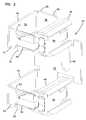
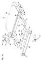
- FIG. 4is a front perspective view of the fanning tray of the system of FIG. 1 .
- FIG. 5is a perspective view of the fanning tray of FIG. 4 with the front cover removed, and various other elements shown exploded from a remainder of the device.
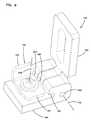
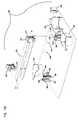
- FIG. 6is a front perspective view of the fanning tray of the system of FIG. 1, with the fanning tray pivoted to the up position.
- FIG. 7is a front perspective view of the fanning tray of FIG. 6 locked in the up position.
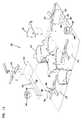
- FIG. 8is a perspective view of one of the hinges for connecting the fanning tray to the rack.
- FIG. 9is a perspective view of the hinge of FIG. 8, shown in the pivoted up position.
- FIG. 10is a perspective view of the hinge of FIG. 9 locked in the pivoted up position.
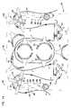
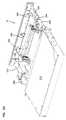
- FIG. 11is a perspective view of a first embodiment of a cable management panel including a chassis and a drawer, with the drawer in the open position, and the tray insert shown exploded from the drawer.
- FIG. 12is a perspective view of the tray insert of FIG. 11 .
- FIG. 13is an exploded perspective view of the tray insert of FIG. 12 .
- FIG. 14is a top view of the tray insert of FIG. 12 .
- FIG. 15is an exploded perspective view of the drawer of FIG. 11 .
- FIG. 16is a further exploded perspective view of the drawer of FIG. 11 .
- FIG. 17is a perspective view of a second embodiment of a cable management panel including a chassis and a drawer, with the drawer in the open position, and the tray insert shown exploded from the drawer.
- FIG. 18is a perspective view of the tray insert of FIG. 17 .
- FIG. 19is an exploded perspective view of the tray insert of FIG. 18 .
- FIG. 20is a top view of the tray insert of FIG. 18 .
- FIG. 21is a perspective view of the tray insert of FIG. 18 with the termination panel in the upper position; adapters are shown in the termination panel, and fanouts are shown in the fanout mounts.
- FIG. 22is a rear perspective view of the tray insert of FIG. 21 with portions exploded.
- FIG. 23is a front elevational of the tray insert of FIG. 21 with portions exploded.
- FIG. 24is a rear perspective of the panel of FIG. 17 with the tray insert positioned in the drawer.
- FIG. 25is a schematic drawing of a telecommunications system showing various cables.
- a telecommunications system 10including an upright rack 12 with two posts 13 for holding various pieces of telecommunications equipment and cable management devices.
- telecommunications equipment 14such as in-line cards 15 behind a cover 17 mounted to rack 12 are linked to other equipment.
- Fanning tray 16assists with management of the cabling between equipment 14 and other equipment such as panels 20 and 21 defining sliding drawers.
- Other equipmentcan include cable storage, or termination or patch panels to cross-connect the equipment 14 , or to inter-connect or cross-connect to other equipment in an adjacent rack or at a remote location.
- first panels 20assist with management and storage of the cables connected to equipment 14 .
- Second panels 21allow for patching of the cables to each other or to other cables.
- Vertical cable guides 22further assist with cable management.
- vertical cable guides 22define vertical cable pathways 23 on rack 12 .
- Vertical cable guides 22 in the preferred embodimentare comprised of individual elements or guides 30 which define a vertical channel 32 extending along rack 12 in the desired locations for cable management.
- Guides 30each include a main body 34 with a base 36 defining a fastener hole 38 for mounting to rack 12 with a fastener.
- First and second arms 40 , 42 on one side of base 36cooperate with third and fourth arms 44 , 46 on an opposite side of base 36 to define vertical channel 32 .
- Arms 40 , 42each include a finger 41 , 43 facing base 36 , and extending toward third and fourth arms 44 , 46 .
- Bend radius limiters 48snap onto third and fourth arms 44 , 46 to provide cable bend radius protection for cable guides 22 .
- First and second tabs 50 , 52snap mount to apertures 54 , 56 in third and fourth arms to further provide an enclosed area for holding cables in vertical channel 32 .
- Tabs 50 , 52are made from flexible material such as molded polyethylene propylene. Ends 51 , 53 can be flexed outside of fingers 41 , 43 to allow cables to be inserted or removed from channel 32 .
- Tabs 50 , 52are flexed outwardly as shown in FIG. 2 .
- Tabs 50 , 52are flexed back inwardly behind fingers 41 , 43 to retain the cables.
- Guides 30are mounted in vertical alignment to define channel 32 along each side of rack 12 .
- Guides 30define gaps 33 for cables to exit channel 32 .
- Guides 30are spaced vertically along posts 13 to define gaps 35 between guides 30 for cables to exit.
- Other vertical cable guidesare anticipated for defining the vertical channels along the sides of rack 12 .
- Guides 30are flipped upside down to populate the other side of the rack.
- fanning tray 16includes a fanning strip 124 for receiving cables extending in a vertical direction toward fanning tray 16 (as shown in FIG. 1 ).
- Fanning strip 124includes a base 130 with horizontal fingers 134 and spaces 136 .
- a cover 125is removable from fanning strip 124 to expose an interior 138 of fanning tray 16 which communicates with spaces 136 and open ends or exits 130 , 132 .
- Fanning strip 124includes a horizontal bottom tray 126 .
- Fingers 134include bend radius limiters 148 snap mounted to a main body 142 . At an end of main body 142 of each finger 134 is a downward tab 144 to assist with cable retention.
- Hinges 140allow for mounting of fanning tray 16 to rack 12 with fasteners.
- Cover 125includes two apertures 150 , 152 for receipt of upper tabs 154 , 156 on fanning tray 16 .
- Fingers 158 , 160 on cover 125include latches 162 , 164 for releasably latching cover 125 to lower tabs 166 , 168 of fanning tray 16 .
- Expandable boss 165is expanded by flipping latch 162 , 164 to the closed position as shown, wherein the boss is held in slot 167 of lower tabs 166 , 168 . Lips 169 help support cover 125 .
- radius limiters 170 , 172 , 174 , and 176are positioned adjacent to ends 130 , 132 to protect cables exiting and entering fanning tray 16 at ends 130 , 132 .
- Each limiter 170 , 177 , 174 , 176further includes a retention tab 177 .
- fanning tray 16pivots upwardly about a hinge axis 178 .
- the pivoted up positionis approximately 90 degrees from the vertical axis.
- Hinges 140allow for the upward movement of fanning tray 16 so as to allow access by the user to the space behind fanning tray 16 in rack 12 .
- Such spacemay include rack mounted equipment 27 , such as equipment cooling fans, as shown in FIG. 1 .
- Fanning tray 16is mounted outside the rack space, the space between posts 13 , so that the space can be used by additional equipment, such as the cooling fans.
- Hinge 140includes a first portion 180 defining an aperture 182 for receipt of a fastener for mounting hinge 140 to rack 12 .
- a second portion 184 of hinge 140is hingedly mounted to first portion 180 about hinge axis 176 .
- a hinge pin 186defines hinge axis 176 linking first portion 180 to second portion 184 .
- Second portion 184defines an aperture 188 for receipt of a fastener 190 for receipt in opening 192 of fanning tray 16 to mount second portion 184 to fanning tray 16 .
- Fanning tray 16includes a lock 192 for locking the fanning tray in the pivoted up position as shown in FIGS. 6 and 7.
- Lock 192includes a rotating tab 193 .
- Tab 193includes a handle end 194 and a distal end 195 .
- First portion 180 of hinge 140includes a slot 196
- second portionincludes slots 197 .
- slots 196 , 197are aligned.
- Tab 193can be rotated 90 degrees about an axis 198 from the position of FIGS. 6 and 9, to the position of FIGS. 7 and 10. In the rotated position, distal end 195 of tab 193 is positioned in slots 196 , 197 .
- tab 193prevents fanning tray 16 from rotating back to the down position.
- Lock 192allows for hands-free access to the area behind fanning tray 16 .
- Tab 193is rotated back to the position of FIGS. 6 and 9 to allow the fanning tray to rotate back to the down position.
- Cables 24 , 25 from equipment 14enter fanning tray 16 through spaces 136 and onto interior 138 .
- the cablesextend horizontally in bottom tray 126 to exit on either end 130 , 132 into vertical cable guides 22 .
- From vertical cable guides 22the cables enter one of first panels 20 or are directed to another rack.
- From panel 20the cables are directed to one of second panels 21 .
- From panels 20 or 21the cables can be further directed back to equipment 14 or to another rack.
- Panels 20 , 21can be in accordance with any of a variety of structures for storing, managing, or terminating optical fibers.
- panels 20 , 21include movable drawers 212 (See FIGS. 15 and 16) which allow for selective opening to expose an interior of the drawer, and for selective closing to protect the drawer's interior.
- Panels 20 , 21can include structures for cable management as in accordance with copending application Ser. No. 09/900,465, which is incorporated by reference herein.
- Panels 20 , 21preferably include a cable take-up mechanism 248 for managing the cables entering or exiting panels 20 , 21 . Cable take-up mechanism 248 operates in a similar manner as in application Ser. No. 09/900,485, to take up slack associated with a sliding drawer.
- Panels 20 , 21may include cable management structure, for example, devices for storing the cables or connecting the cables to other cables or fiberoptic devices. Panels 20 , 21 may also include attenuators, couplers, switches, wave division multiplexers, splitters or splices. Panel 20 include a chassis 210 with a drawer 212 slidably mounted within chassis 210 . Together chassis 210 and drawer 211 define a drawer assembly 25 . Drawer 212 is slidable relative to chassis 210 by way of one, preferably two drawer slides 213 on opposite sides of chassis 210 . The drawer slides 213 can be any type of linear slide that allows drawer 212 to slide out to the position of FIG. 9, and to then slide horizontally into chassis 210 .
- Each drawer 212includes two latches 214 to secure the drawer 212 in a closed position.
- a latch tab 215engages an aperture 216 in chassis 210 to hold the drawer in the closed position.
- Panel 20includes brackets 220 on opposite sides to mount panel 20 to rack 12 .
- Each drawer 212includes a base 242 , a front wall 244 , and a rear wall 246 . Note that the drawer 212 is absent of sidewalls, or is “sidewall free.” This structure allows for cable entry and exit and prevents cable damage during sliding movement of drawer 212 when accessing the cables and connectors or other devices in drawer 212 .
- Base 242 , front wall 244 , and rear wall 247together define a storage interior 245 for holding and storing the cables. Cable access to storage interior 245 is through cable access or entries 218 , 219 .
- Front wall 244includes a front faceplate 245 and a front plate 253 fastened together at front tabs 255 of base 242 .
- Each storage interior 245is sized for receiving cable management and/or distribution structures.
- the cables and management or distribution structures in the storage interior 245are protected.
- the distribution structurescan be conveniently mounted on a tray insert 230 that drops into storage interior 245 . This allows for convenient structuring of the drawer 212 to serve one or more desired functions in the panel 20 . Examples of tray inserts are described in co-pending and commonly assigned U.S. patent application Ser. No. 09/649,398, which is a continuation-in-part of application Ser. No. 09/490,379 (also co-pending and commonly assigned), and application Ser. No. 09/900,465, each of which is incorporated by reference herein.
- Each drawer 212includes a take-up mechanism 248 on each side to manage optical fibers entering and exiting panel 20 .
- each take-up mechanism 248includes a push member or radius limiter 250 .
- radius limiter 250includes a vertically oriented curved wall 252 and a trough section 254 adjacent to the vertically curved wall 252 .
- Cover members 256help to retain cables in the trough section 254 .
- Ends 258 of cover members 256pivot upwardly to allow cable access.
- Radius limiter 250snap mounts to slide member 251 beneath base 242 .
- Radius limiter 248is preferably slidably mounted relative to drawer 212 . Movement of radius limiter 248 is controlled with synchronized movement with drawer 212 to insure that the cables do not bend too sharply when the drawer is being opened or closed relative to chassis 210 . If the cables were bent too sharply, this may cause of signal strength or loss of transmission.
- the cable management panel 20includes a control mechanism 260 that is secured to the drawer to synchronize slidable movement of cable radius limiter 250 relative to slidable movement of drawer 212 within chassis 210 .
- the control mechanism 260includes a rotating wheel 262 connected to slide member 251 .
- a preferred 262 wheelwill include a compressible ring that circumscribes the wheel to help provide for a smooth interface and to introduce some friction for smooth operation.
- the axis of rotation of wheel 262is a vertical in the preferred embodiment.
- Tray insert 230includes various cable management devices, such as guides 232 including curved walls 234 and cable retention tabs 236 arranged on tray insert 230 to provide for cable management pathways for winding of slack loops of cable that enter drawer 212 through side entries 218 , 219 and take up mechanisms 248 . Further cable guides 233 including vertical walls 236 and tabs 237 also provide for cable management. Together guides 232 , 233 define selectable cable pathways to take up the length of cable so no excess slack hangs out of the drawer.
- FIG. 14shows one example cable pathway A on tray insert 230 .
- a further cable radius limiter 270is slidably mounted to tray insert 230 .
- Cable radius limiter 270includes an outer curved surface 272 , and cable retention tabs 274 .
- An elongated slide 276extends from cable radius limiter 270 and includes an inner slot 278 between elongated arms 288 , 289 and opposed outer edges 280 .
- Tray insert 230includes a threaded shaft 282 projecting upwardly and received in slot 278 .
- a threaded wheel 284mounts to threaded'shaft 282 to selectively lock cable radius limiter 270 in position. Slide 276 and cable radius limiter 270 are held in place through a clamping force generated by threaded wheel 284 on slide 276 . Once threaded wheel 284 is loosened, cable radius limiter 270 through slide 276 can slide toward the front edge of the drawer insert 230 as desired, such as to selectively release the slack held by cable radius limiter 270 .
- Two tabs 286capture elongated arm 288 of slide 276 to guide slide 276 linearly. One tab 286 engages one of outer edges 280 , and the other tab 286 is positioned in slot 278 .
- Tray insert 230is held in drawer 212 by latches 290 mounted to front tabs 255 . Rear tabs 292 of tray insert 230 fit into rear slots 294 of drawer 212 to further retain tray insert 230 .
- second panel 21 with a tray insert 330is shown.
- Various cable guides 334 , 336 , 338 , and 340are positioned around drawer insert 330 for defining various cable pathways.
- Cable fanout mounts 344are also provided on drawer insert 330 . Fanout mounts 344 allow for multi-fiber cables to fan out into individual fibers, such as for termination at a panel 350 .
- Panel 350can hold fiber optic adapters 349 received in openings 352 .
- Each adapterreceives one or more fiberoptic connectors on opposite sides of the adapter. Any type of mating adapter/connector system can be used, such as MU adapter/connector types.
- panel 350is slidably mounted to tray insert 330 through slide module 360 .
- Each slide module 360is modular and includes a pivoting handle 362 .
- Handles 362allow for release of panel 350 from a locked position to slide upwardly on slide walls 364 .
- Slide handle 370retains panel 350 with slide walls 364 .
- Slide handle 370is spring loaded to resist movement of handle portion 372 away from slide wall 364 .
- Slide handle 370can be moved manually to allow panel 350 to be removed from slide walls 364 , such as for repair or replacement.
- a groove and rail arrangementallows for vertical sliding of panel 350 and slide modules 360 . Grooves 376 on slide walls 364 receive rails 374 on slide module 360 .
- both handles 362are pivoted upwardly to withdraw tab 378 of slide handles 370 from lower notch 380 .
- Handlesinclude end 365 which pulls slide module 360 upwardly.
- Lower notch 380includes an upper ramp surface 381 which allows tab 378 to be withdrawn against the spring (not shown) of slide handle 370 .
- Panel 350is slid upwardly in the direction of arrow C (see FIG. 18 ). In the upper position, panel 350 and its termination locations are more easily accessed, for making corrections or disconnecting connectors from adapters (See FIG. 22 ). Panel 350 remains in the upper position when tabs 378 reside in upper notches 382 .
- Notch 382has a lower ramp surface 384 to withdraw tab 378 , to allow downwardly sliding by downward pushing on panel 350 and/or slide modules 360 .
- FIG. 20shows an example cabling for tray insert 330 .
- Cables D and Eenter drawer 21 at side entry 218 (when the drawer is closed), pass through cable radius limiter 248 on the right side and terminate at panel 350 .
- multi-fiber cables D, Eare used.
- the cables D, Efan out at fanouts 345 into individual cables DD, EE.
- Cables DD and EEeach include connectorized ends for mating with an adapter.
- jumper cables Fcan be used to connect cables DD to EE, or DD to DD.
- cables Gcan be used to exit drawer 212 on an opposite side entry 219 .
- Further cables Hcan be used to exit at side entry 218 .
- FIG. 25shows a schematic system 11 where rack 12 holds equipment 14 , fanning trays 16 , storage panels 20 , and patching drawers 21 .
- Multifiber cables 1000(32 in number for example) extend from equipment 14 , labeled EQUIPMENT 1 , to fanning tray 16 labeled FANNING 1 .
- From fanning tray 16sixteen cables extend into one storage panel 20 , labeled STORE 1 , and sixteen extend into another storage panel 20 , labeled STORE 2 .
Landscapes
- Engineering & Computer Science (AREA)
- Physics & Mathematics (AREA)
- Architecture (AREA)
- Civil Engineering (AREA)
- Structural Engineering (AREA)
- Microelectronics & Electronic Packaging (AREA)
- General Physics & Mathematics (AREA)
- Optics & Photonics (AREA)
- Light Guides In General And Applications Therefor (AREA)
Abstract
Description
Claims (9)
Priority Applications (1)
| Application Number | Priority Date | Filing Date | Title |
|---|---|---|---|
| US10/201,623US6677520B1 (en) | 2002-07-22 | 2002-07-22 | Fanning tray |
Applications Claiming Priority (1)
| Application Number | Priority Date | Filing Date | Title |
|---|---|---|---|
| US10/201,623US6677520B1 (en) | 2002-07-22 | 2002-07-22 | Fanning tray |
Publications (2)
| Publication Number | Publication Date |
|---|---|
| US6677520B1true US6677520B1 (en) | 2004-01-13 |
| US20040011546A1 US20040011546A1 (en) | 2004-01-22 |
Family
ID=29780250
Family Applications (1)
| Application Number | Title | Priority Date | Filing Date |
|---|---|---|---|
| US10/201,623Expired - LifetimeUS6677520B1 (en) | 2002-07-22 | 2002-07-22 | Fanning tray |
Country Status (1)
| Country | Link |
|---|---|
| US (1) | US6677520B1 (en) |
Cited By (88)
| Publication number | Priority date | Publication date | Assignee | Title |
|---|---|---|---|---|
| US20050025444A1 (en)* | 2003-07-31 | 2005-02-03 | Barnes Kathleen M. | Slide arrangement for cable drawer |
| US20050115736A1 (en)* | 2003-12-01 | 2005-06-02 | Levesque Stewart A. | Cable management system |
| US6983046B2 (en)* | 2002-02-08 | 2006-01-03 | Massey Mike L | Routing and labeling system for wires, cables, fibers, and the like |
| US20080085092A1 (en)* | 2006-10-04 | 2008-04-10 | Barnes Kathleen M | Slide arrangement for cable drawer |
| US20080093958A1 (en)* | 2006-10-20 | 2008-04-24 | Peterson Karl J | High density telecommunications mounting drawer |
| US20090310929A1 (en)* | 2007-10-10 | 2009-12-17 | Adc Telecommunications, Inc. | Optical fiber interconnection apparatus |
| US20100054682A1 (en)* | 2008-08-29 | 2010-03-04 | Cooke Terry L | Independently Translatable Modules and Fiber Optic Equipment Trays in Fiber Optic Equipment |
| US20100054683A1 (en)* | 2008-08-29 | 2010-03-04 | Cooke Terry L | Rear-Installable Fiber Optic Modules and Equipment |
| US20100061691A1 (en)* | 2008-09-08 | 2010-03-11 | Ortronics, Inc. | Horizontal fiber optic patching assembly |
| US20100220967A1 (en)* | 2009-02-27 | 2010-09-02 | Cooke Terry L | Hinged Fiber Optic Module Housing and Module |
| US20100272410A1 (en)* | 2009-04-24 | 2010-10-28 | Dennis Krampotich | Radius limiter cable retention bracket, clamp and panel |
| US20100296790A1 (en)* | 2009-05-21 | 2010-11-25 | Cooke Terry L | Fiber Optic Equipment Supporting Moveable Fiber Optic Equipment Tray(s) and Module(s), and Related Equipment and Methods |
| US20100301720A1 (en)* | 2009-05-12 | 2010-12-02 | Chad Anderson | Cable management module with pivot cover assembly |
| US20110116757A1 (en)* | 2008-07-04 | 2011-05-19 | Tyco Electronics Raychem Bvba | Optical fibre distribution module with storage reels and organiser |
| US8433171B2 (en) | 2009-06-19 | 2013-04-30 | Corning Cable Systems Llc | High fiber optic cable packing density apparatus |
| US20130240469A1 (en)* | 2010-11-03 | 2013-09-19 | Telefonaktiebolaget Lm Ericsson (Publ) | Rack module |
| US8542973B2 (en) | 2010-04-23 | 2013-09-24 | Ccs Technology, Inc. | Fiber optic distribution device |
| US8593828B2 (en) | 2010-02-04 | 2013-11-26 | Corning Cable Systems Llc | Communications equipment housings, assemblies, and related alignment features and methods |
| US8625950B2 (en) | 2009-12-18 | 2014-01-07 | Corning Cable Systems Llc | Rotary locking apparatus for fiber optic equipment trays and related methods |
| US8660397B2 (en) | 2010-04-30 | 2014-02-25 | Corning Cable Systems Llc | Multi-layer module |
| US8662760B2 (en) | 2010-10-29 | 2014-03-04 | Corning Cable Systems Llc | Fiber optic connector employing optical fiber guide member |
| US8699838B2 (en) | 2009-05-14 | 2014-04-15 | Ccs Technology, Inc. | Fiber optic furcation module |
| US8705926B2 (en) | 2010-04-30 | 2014-04-22 | Corning Optical Communications LLC | Fiber optic housings having a removable top, and related components and methods |
| US8712206B2 (en) | 2009-06-19 | 2014-04-29 | Corning Cable Systems Llc | High-density fiber optic modules and module housings and related equipment |
| US8718436B2 (en) | 2010-08-30 | 2014-05-06 | Corning Cable Systems Llc | Methods, apparatuses for providing secure fiber optic connections |
| CN103828161A (en)* | 2011-03-16 | 2014-05-28 | 迪特尔·拉姆绍尔 | cable grabber |
| US8879881B2 (en) | 2010-04-30 | 2014-11-04 | Corning Cable Systems Llc | Rotatable routing guide and assembly |
| US8913866B2 (en) | 2010-03-26 | 2014-12-16 | Corning Cable Systems Llc | Movable adapter panel |
| US8953924B2 (en) | 2011-09-02 | 2015-02-10 | Corning Cable Systems Llc | Removable strain relief brackets for securing fiber optic cables and/or optical fibers to fiber optic equipment, and related assemblies and methods |
| US8985862B2 (en) | 2013-02-28 | 2015-03-24 | Corning Cable Systems Llc | High-density multi-fiber adapter housings |
| US8989547B2 (en) | 2011-06-30 | 2015-03-24 | Corning Cable Systems Llc | Fiber optic equipment assemblies employing non-U-width-sized housings and related methods |
| US8995812B2 (en) | 2012-10-26 | 2015-03-31 | Ccs Technology, Inc. | Fiber optic management unit and fiber optic distribution device |
| US9002166B2 (en) | 2011-10-07 | 2015-04-07 | Adc Telecommunications, Inc. | Slidable fiber optic connection module with cable slack management |
| US9008485B2 (en) | 2011-05-09 | 2015-04-14 | Corning Cable Systems Llc | Attachment mechanisms employed to attach a rear housing section to a fiber optic housing, and related assemblies and methods |
| US9020320B2 (en) | 2008-08-29 | 2015-04-28 | Corning Cable Systems Llc | High density and bandwidth fiber optic apparatuses and related equipment and methods |
| US9022814B2 (en) | 2010-04-16 | 2015-05-05 | Ccs Technology, Inc. | Sealing and strain relief device for data cables |
| US20150122751A1 (en)* | 2012-06-07 | 2015-05-07 | Intal Tech Ltd. | Electrononic equipment building blocks for rack mounting |
| US9042702B2 (en) | 2012-09-18 | 2015-05-26 | Corning Cable Systems Llc | Platforms and systems for fiber optic cable attachment |
| US9038832B2 (en) | 2011-11-30 | 2015-05-26 | Corning Cable Systems Llc | Adapter panel support assembly |
| US9059578B2 (en) | 2009-02-24 | 2015-06-16 | Ccs Technology, Inc. | Holding device for a cable or an assembly for use with a cable |
| US9057859B2 (en) | 2011-10-07 | 2015-06-16 | Adc Telecommunications, Inc. | Slidable fiber optic connection module with cable slack management |
| US9075217B2 (en) | 2010-04-30 | 2015-07-07 | Corning Cable Systems Llc | Apparatuses and related components and methods for expanding capacity of fiber optic housings |
| US9075216B2 (en) | 2009-05-21 | 2015-07-07 | Corning Cable Systems Llc | Fiber optic housings configured to accommodate fiber optic modules/cassettes and fiber optic panels, and related components and methods |
| US9075203B2 (en) | 2012-01-17 | 2015-07-07 | Adc Telecommunications, Inc. | Fiber optic adapter block |
| US9116324B2 (en) | 2010-10-29 | 2015-08-25 | Corning Cable Systems Llc | Stacked fiber optic modules and fiber optic equipment configured to support stacked fiber optic modules |
| US9128262B2 (en) | 2013-02-05 | 2015-09-08 | Adc Telecommunications, Inc. | Slidable telecommunications tray with cable slack management |
| US9170391B2 (en) | 2011-10-07 | 2015-10-27 | Adc Telecommunications, Inc. | Slidable fiber optic connection module with cable slack management |
| US9195021B2 (en) | 2012-09-21 | 2015-11-24 | Adc Telecommunications, Inc. | Slidable fiber optic connection module with cable slack management |
| US9213161B2 (en) | 2010-11-05 | 2015-12-15 | Corning Cable Systems Llc | Fiber body holder and strain relief device |
| US9250409B2 (en) | 2012-07-02 | 2016-02-02 | Corning Cable Systems Llc | Fiber-optic-module trays and drawers for fiber-optic equipment |
| US9279951B2 (en) | 2010-10-27 | 2016-03-08 | Corning Cable Systems Llc | Fiber optic module for limited space applications having a partially sealed module sub-assembly |
| US9285557B2 (en) | 2012-06-27 | 2016-03-15 | Tyco Electronics Raychem Bvba | High density telecommunications chassis with cable management |
| US9360648B2 (en) | 2011-09-16 | 2016-06-07 | Commscope Technologies Llc | Systems and methods for the management of fiber optic cables |
| US9389384B2 (en) | 2013-02-27 | 2016-07-12 | Commscope Technologies Llc | Slidable fiber optic connection module with cable slack management |
| US20160223770A1 (en)* | 2013-09-13 | 2016-08-04 | Tyco Electronics Raychem Bvba | Fiber optic termination assembly |
| US9500829B2 (en) | 2011-09-16 | 2016-11-22 | Commscope Technologies Llc | Systems and methods for the management of fiber optic cables |
| US9519118B2 (en) | 2010-04-30 | 2016-12-13 | Corning Optical Communications LLC | Removable fiber management sections for fiber optic housings, and related components and methods |
| US9521766B2 (en) | 2012-06-27 | 2016-12-13 | CommScope Connectivity Belgium BVBA | High density telecommunications systems with cable management and heat dissipation features |
| US9541726B2 (en) | 2013-04-24 | 2017-01-10 | Adc Czech Republic, S.R.O. | Optical fiber distribution system |
| US9568699B2 (en) | 2013-01-29 | 2017-02-14 | CommScope Connectivity Belgium BVBA | Optical fiber distribution system |
| US9632270B2 (en) | 2010-04-30 | 2017-04-25 | Corning Optical Communications LLC | Fiber optic housings configured for tool-less assembly, and related components and methods |
| US9645317B2 (en) | 2011-02-02 | 2017-05-09 | Corning Optical Communications LLC | Optical backplane extension modules, and related assemblies suitable for establishing optical connections to information processing modules disposed in equipment racks |
| US9720195B2 (en) | 2010-04-30 | 2017-08-01 | Corning Optical Communications LLC | Apparatuses and related components and methods for attachment and release of fiber optic housings to and from an equipment rack |
| US10082636B2 (en) | 2012-09-21 | 2018-09-25 | Commscope Technologies Llc | Slidable fiber optic connection module with cable slack management |
| US10247886B2 (en) | 2014-12-10 | 2019-04-02 | Commscope Technologies Llc | Fiber optic cable slack management module |
| US10261281B2 (en) | 2015-04-03 | 2019-04-16 | CommScope Connectivity Belgium BVBA | Telecommunications distribution elements |
| US10409020B2 (en) | 2013-04-24 | 2019-09-10 | CommScope Connectivity Belgium BVBA | Universal mounting mechanism for mounting a telecommunications chassis to a telecommunciations fixture |
| US10539757B2 (en) | 2016-04-19 | 2020-01-21 | Commscope, Inc. Of North Carolina | Telecommunications chassis with slidable trays |
| US10670822B2 (en) | 2017-06-28 | 2020-06-02 | Afl Telecommunications Llc | High density patch panel with modular cassettes |
| US11215767B2 (en) | 2017-06-07 | 2022-01-04 | Commscope Technologies Llc | Fiber optic adapter and cassette |
| US11237348B2 (en) | 2019-04-17 | 2022-02-01 | Afl Ig Llc | Patch panel with lifting cassette removal |
| US11256054B2 (en) | 2018-04-16 | 2022-02-22 | Commscope Technologies Llc | Adapter structure |
| US11294136B2 (en) | 2008-08-29 | 2022-04-05 | Corning Optical Communications LLC | High density and bandwidth fiber optic apparatuses and related equipment and methods |
| US11385429B2 (en) | 2017-10-18 | 2022-07-12 | Commscope Technologies Llc | Fiber optic connection cassette |
| US11409067B2 (en) | 2018-08-31 | 2022-08-09 | CommScope Connectivity Belgium BVBA | Frame assemblies for optical fiber distribution elements |
| US11448845B2 (en) | 2018-08-31 | 2022-09-20 | CommScope Connectivity Belgium BVBA | Frame assemblies for optical fiber distribution elements |
| US11448831B2 (en) | 2018-08-31 | 2022-09-20 | CommScope Connectivity Belgium BVBA | Frame assemblies for optical fiber distribution elements |
| US11448844B2 (en) | 2018-08-31 | 2022-09-20 | CommScope Connectivity Belgium BVBA | Frame assemblies for optical fiber distribution elements |
| US11635578B2 (en) | 2018-04-17 | 2023-04-25 | CommScope Connectivity Belgium BVBA | Telecommunications distribution elements |
| US11674345B2 (en) | 2016-04-19 | 2023-06-13 | Commscope, Inc. Of North Carolina | Door assembly for a telecommunications chassis with a combination hinge structure |
| US20230314751A1 (en)* | 2020-08-14 | 2023-10-05 | Commscope Technologies Llc | Optical fiber sheath holders for fiber optic closure organizers |
| US11852882B2 (en) | 2018-02-28 | 2023-12-26 | Commscope Technologies Llc | Packaging assembly for telecommunications equipment |
| US11947177B2 (en) | 2019-01-25 | 2024-04-02 | CommScope Connectivity Belgium BVBA | Frame assemblies for optical fiber distribution elements |
| US12007615B2 (en) | 2018-10-23 | 2024-06-11 | CommScope Connectivity Belgium BVBA | Frame assemblies for optical fiber distribution elements |
| US12050358B2 (en) | 2018-08-31 | 2024-07-30 | CommScope Connectivity Belgium BVBA | Frame assemblies for optical fiber distribution elements |
| US12099246B2 (en) | 2020-01-24 | 2024-09-24 | CommScope Connectivity Belgium BVBA | Telecommunications distribution elements |
| US12174443B2 (en) | 2020-01-22 | 2024-12-24 | CommScope Connectivity Belgium BVBA | Cable termination units for optical fiber distribution elements |
| US12366717B2 (en)* | 2014-09-16 | 2025-07-22 | CommScope Connectivity Belgium BVBA | Telecommunications tray assembly |
Families Citing this family (6)
| Publication number | Priority date | Publication date | Assignee | Title |
|---|---|---|---|---|
| US7945136B2 (en)* | 2009-06-19 | 2011-05-17 | Corning Cable Systems Llc | Mounting of fiber optic cable assemblies within fiber optic shelf assemblies |
| GB2476225B (en)* | 2009-10-14 | 2014-05-07 | Mode Al Ltd | Improvements in racking systems |
| WO2014077792A1 (en)* | 2012-11-16 | 2014-05-22 | Canovate Elektroni̇k Endüstri̇ Ve Ti̇caret Anoni̇m Şi̇rketi̇ | Fiber optic cassettes |
| US10429495B1 (en)* | 2018-04-03 | 2019-10-01 | Hesai Photonics Technology Co., Ltd. | Lidar system and method |
| NL2020934B1 (en)* | 2018-05-15 | 2019-11-21 | Squarell B V | Housing enclosing a printed circuit board |
| WO2019237581A1 (en) | 2018-06-13 | 2019-12-19 | Hesai Photonics Technology Co., Ltd. | Lidar systems and methods |
Citations (9)
| Publication number | Priority date | Publication date | Assignee | Title |
|---|---|---|---|---|
| US3660613A (en)* | 1971-01-21 | 1972-05-02 | Bell Telephone Labor Inc | Serving area connector |
| US4594044A (en)* | 1983-08-08 | 1986-06-10 | Olaf Soot | Rotating truck lift |
| US5640482A (en)* | 1995-08-31 | 1997-06-17 | The Whitaker Corporation | Fiber optic cable management rack |
| US5659655A (en)* | 1996-04-29 | 1997-08-19 | Mcdonnell Douglas Corporation | Optical ribbon cable fanout boxes |
| US5758003A (en)* | 1996-03-15 | 1998-05-26 | Adc Telecommunications, Inc. | High density fiber management |
| US5885112A (en)* | 1997-11-17 | 1999-03-23 | Adc Telecommunications, Inc. | Coax connector bay and drawer |
| US6245998B1 (en)* | 1999-10-27 | 2001-06-12 | Avaya Technology Corp. | Cable management assembly for equipment racks |
| WO2002019005A2 (en) | 2000-08-28 | 2002-03-07 | Adc Telecommunications, Inc. | Cable management panel with sliding drawer |
| US6438310B1 (en) | 2000-01-24 | 2002-08-20 | Adc Telecommunications, Inc. | Cable management panel with sliding drawer |
- 2002
- 2002-07-22USUS10/201,623patent/US6677520B1/ennot_activeExpired - Lifetime
Patent Citations (10)
| Publication number | Priority date | Publication date | Assignee | Title |
|---|---|---|---|---|
| US3660613A (en)* | 1971-01-21 | 1972-05-02 | Bell Telephone Labor Inc | Serving area connector |
| US4594044A (en)* | 1983-08-08 | 1986-06-10 | Olaf Soot | Rotating truck lift |
| US5640482A (en)* | 1995-08-31 | 1997-06-17 | The Whitaker Corporation | Fiber optic cable management rack |
| US5758003A (en)* | 1996-03-15 | 1998-05-26 | Adc Telecommunications, Inc. | High density fiber management |
| US5659655A (en)* | 1996-04-29 | 1997-08-19 | Mcdonnell Douglas Corporation | Optical ribbon cable fanout boxes |
| US5885112A (en)* | 1997-11-17 | 1999-03-23 | Adc Telecommunications, Inc. | Coax connector bay and drawer |
| US6245998B1 (en)* | 1999-10-27 | 2001-06-12 | Avaya Technology Corp. | Cable management assembly for equipment racks |
| US6438310B1 (en) | 2000-01-24 | 2002-08-20 | Adc Telecommunications, Inc. | Cable management panel with sliding drawer |
| US6504988B1 (en) | 2000-01-24 | 2003-01-07 | Adc Telecommunications, Inc. | Cable management panel with sliding drawer |
| WO2002019005A2 (en) | 2000-08-28 | 2002-03-07 | Adc Telecommunications, Inc. | Cable management panel with sliding drawer |
Cited By (211)
| Publication number | Priority date | Publication date | Assignee | Title |
|---|---|---|---|---|
| US6983046B2 (en)* | 2002-02-08 | 2006-01-03 | Massey Mike L | Routing and labeling system for wires, cables, fibers, and the like |
| US20090226142A1 (en)* | 2003-07-31 | 2009-09-10 | Adc Telecommunications, Inc | Slide arragement for cable drawer |
| US10884210B2 (en) | 2003-07-31 | 2021-01-05 | Commscope Technologies Llc | Slide arrangement for cable drawer |
| US8027558B2 (en) | 2003-07-31 | 2011-09-27 | Adc Telecommunications, Inc. | Slide arrangement for cable drawer |
| US20110110639A1 (en)* | 2003-07-31 | 2011-05-12 | Adc Telecommunications, Inc. | Slide arrangement for cable drawer |
| US7869683B2 (en) | 2003-07-31 | 2011-01-11 | Adc Telecommunications, Inc. | Slide arrangement for cable drawer |
| US7171099B2 (en)* | 2003-07-31 | 2007-01-30 | Adc Telecommunications, Inc. | Slide arrangement for cable drawer |
| US20070098347A1 (en)* | 2003-07-31 | 2007-05-03 | Adc Telecommunications, Inc. | Slide arrangement for cable drawer |
| US7308184B2 (en)* | 2003-07-31 | 2007-12-11 | Adc Telecommunications, Inc. | Slide arrangement for cable drawer |
| US20080069512A1 (en)* | 2003-07-31 | 2008-03-20 | Adc Telecommunications, Inc. | Slide arrangement for cable drawer |
| US11624886B2 (en) | 2003-07-31 | 2023-04-11 | Commscope Technologies Llc | Slide arrangement for cable drawer |
| US9167897B2 (en) | 2003-07-31 | 2015-10-27 | Tyco Electronics Services Gmbh | Slide arrangement for cable drawer |
| US11287594B2 (en) | 2003-07-31 | 2022-03-29 | Commscope Technologies Llc | Slide arrangement for cable drawer |
| US7499623B2 (en) | 2003-07-31 | 2009-03-03 | Adc Telecommunications, Inc. | Slide arrangement for cable drawer |
| US8639081B2 (en) | 2003-07-31 | 2014-01-28 | Adc Telecommunications, Inc. | Slide arrangement for cable drawer |
| US20050025444A1 (en)* | 2003-07-31 | 2005-02-03 | Barnes Kathleen M. | Slide arrangement for cable drawer |
| US9844266B2 (en) | 2003-07-31 | 2017-12-19 | Commscope Technologies Llc | Slide arrangement for cable drawer |
| US10226123B2 (en) | 2003-07-31 | 2019-03-12 | Commscope Technologies Llc | Slide arrangement for cable drawer |
| US10598885B2 (en) | 2003-07-31 | 2020-03-24 | Commscope Technologies Llc | Slide arrangement for cable drawer |
| US9565938B2 (en) | 2003-07-31 | 2017-02-14 | Commscope Technologies Llc | Slide arrangement for cable drawer |
| US20050115737A1 (en)* | 2003-12-01 | 2005-06-02 | Levesque Stewart A. | Cable management system |
| US7026553B2 (en) | 2003-12-01 | 2006-04-11 | Ortronics, Inc. | Cable management system |
| US20050115736A1 (en)* | 2003-12-01 | 2005-06-02 | Levesque Stewart A. | Cable management system |
| US6946605B2 (en)* | 2003-12-01 | 2005-09-20 | Ortronics, Inc. | Cable management system |
| US7409137B2 (en) | 2006-10-04 | 2008-08-05 | Adc Telecommunications, Inc. | Slide arrangement for cable drawer |
| US20080085092A1 (en)* | 2006-10-04 | 2008-04-10 | Barnes Kathleen M | Slide arrangement for cable drawer |
| US20080093958A1 (en)* | 2006-10-20 | 2008-04-24 | Peterson Karl J | High density telecommunications mounting drawer |
| US8727458B2 (en) | 2006-10-20 | 2014-05-20 | Adc Telecommunications, Inc. | High density telecommunications mounting drawer |
| US20090310929A1 (en)* | 2007-10-10 | 2009-12-17 | Adc Telecommunications, Inc. | Optical fiber interconnection apparatus |
| US20110116757A1 (en)* | 2008-07-04 | 2011-05-19 | Tyco Electronics Raychem Bvba | Optical fibre distribution module with storage reels and organiser |
| US11086089B2 (en) | 2008-08-29 | 2021-08-10 | Corning Optical Communications LLC | High density and bandwidth fiber optic apparatuses and related equipment and methods |
| US20100054683A1 (en)* | 2008-08-29 | 2010-03-04 | Cooke Terry L | Rear-Installable Fiber Optic Modules and Equipment |
| US11294135B2 (en) | 2008-08-29 | 2022-04-05 | Corning Optical Communications LLC | High density and bandwidth fiber optic apparatuses and related equipment and methods |
| US8452148B2 (en) | 2008-08-29 | 2013-05-28 | Corning Cable Systems Llc | Independently translatable modules and fiber optic equipment trays in fiber optic equipment |
| US11609396B2 (en) | 2008-08-29 | 2023-03-21 | Corning Optical Communications LLC | High density and bandwidth fiber optic apparatuses and related equipment and methods |
| US20100054682A1 (en)* | 2008-08-29 | 2010-03-04 | Cooke Terry L | Independently Translatable Modules and Fiber Optic Equipment Trays in Fiber Optic Equipment |
| US10416405B2 (en) | 2008-08-29 | 2019-09-17 | Corning Optical Communications LLC | Independently translatable modules and fiber optic equipment trays in fiber optic equipment |
| US11294136B2 (en) | 2008-08-29 | 2022-04-05 | Corning Optical Communications LLC | High density and bandwidth fiber optic apparatuses and related equipment and methods |
| US11092767B2 (en) | 2008-08-29 | 2021-08-17 | Corning Optical Communications LLC | High density and bandwidth fiber optic apparatuses and related equipment and methods |
| US8184938B2 (en) | 2008-08-29 | 2012-05-22 | Corning Cable Systems Llc | Rear-installable fiber optic modules and equipment |
| US10126514B2 (en) | 2008-08-29 | 2018-11-13 | Corning Optical Communications, Llc | Independently translatable modules and fiber optic equipment trays in fiber optic equipment |
| US10422971B2 (en) | 2008-08-29 | 2019-09-24 | Corning Optical Communicatinos LLC | High density and bandwidth fiber optic apparatuses and related equipment and methods |
| US10222570B2 (en) | 2008-08-29 | 2019-03-05 | Corning Optical Communications LLC | Independently translatable modules and fiber optic equipment trays in fiber optic equipment |
| US10120153B2 (en) | 2008-08-29 | 2018-11-06 | Corning Optical Communications, Llc | Independently translatable modules and fiber optic equipment trays in fiber optic equipment |
| US10852499B2 (en) | 2008-08-29 | 2020-12-01 | Corning Optical Communications LLC | High density and bandwidth fiber optic apparatuses and related equipment and methods |
| US10094996B2 (en) | 2008-08-29 | 2018-10-09 | Corning Optical Communications, Llc | Independently translatable modules and fiber optic equipment trays in fiber optic equipment |
| US10606014B2 (en) | 2008-08-29 | 2020-03-31 | Corning Optical Communications LLC | Independently translatable modules and fiber optic equipment trays in fiber optic equipment |
| US10444456B2 (en) | 2008-08-29 | 2019-10-15 | Corning Optical Communications LLC | High density and bandwidth fiber optic apparatuses and related equipment and methods |
| US10459184B2 (en) | 2008-08-29 | 2019-10-29 | Corning Optical Communications LLC | High density and bandwidth fiber optic apparatuses and related equipment and methods |
| US9910236B2 (en) | 2008-08-29 | 2018-03-06 | Corning Optical Communications LLC | High density and bandwidth fiber optic apparatuses and related equipment and methods |
| US9020320B2 (en) | 2008-08-29 | 2015-04-28 | Corning Cable Systems Llc | High density and bandwidth fiber optic apparatuses and related equipment and methods |
| US11754796B2 (en) | 2008-08-29 | 2023-09-12 | Corning Optical Communications LLC | Independently translatable modules and fiber optic equipment trays in fiber optic equipment |
| US12072545B2 (en) | 2008-08-29 | 2024-08-27 | Corning Optical Communications LLC | High density and bandwidth fiber optic apparatuses and related equipment and methods |
| US10564378B2 (en) | 2008-08-29 | 2020-02-18 | Corning Optical Communications LLC | High density and bandwidth fiber optic apparatuses and related equipment and methods |
| US20100061691A1 (en)* | 2008-09-08 | 2010-03-11 | Ortronics, Inc. | Horizontal fiber optic patching assembly |
| US7697811B2 (en)* | 2008-09-08 | 2010-04-13 | Ortronics, Inc. | Horizontal fiber optic patching assembly |
| US9059578B2 (en) | 2009-02-24 | 2015-06-16 | Ccs Technology, Inc. | Holding device for a cable or an assembly for use with a cable |
| US20100220967A1 (en)* | 2009-02-27 | 2010-09-02 | Cooke Terry L | Hinged Fiber Optic Module Housing and Module |
| US20100272410A1 (en)* | 2009-04-24 | 2010-10-28 | Dennis Krampotich | Radius limiter cable retention bracket, clamp and panel |
| WO2010123992A3 (en)* | 2009-04-24 | 2011-07-21 | Adc Telecommunications, Inc. | Radius limiter cable retention bracket, clamp and panel |
| US20100301720A1 (en)* | 2009-05-12 | 2010-12-02 | Chad Anderson | Cable management module with pivot cover assembly |
| US8699838B2 (en) | 2009-05-14 | 2014-04-15 | Ccs Technology, Inc. | Fiber optic furcation module |
| US8280216B2 (en) | 2009-05-21 | 2012-10-02 | Corning Cable Systems Llc | Fiber optic equipment supporting moveable fiber optic equipment tray(s) and module(s), and related equipment and methods |
| US20100296790A1 (en)* | 2009-05-21 | 2010-11-25 | Cooke Terry L | Fiber Optic Equipment Supporting Moveable Fiber Optic Equipment Tray(s) and Module(s), and Related Equipment and Methods |
| US9075216B2 (en) | 2009-05-21 | 2015-07-07 | Corning Cable Systems Llc | Fiber optic housings configured to accommodate fiber optic modules/cassettes and fiber optic panels, and related components and methods |
| US20100296791A1 (en)* | 2009-05-21 | 2010-11-25 | Elli Makrides-Saravanos | Fiber Optic Equipment Guides and Rails Configured with Stopping Position(s), and Related Equipment and Methods |
| US8538226B2 (en) | 2009-05-21 | 2013-09-17 | Corning Cable Systems Llc | Fiber optic equipment guides and rails configured with stopping position(s), and related equipment and methods |
| US8712206B2 (en) | 2009-06-19 | 2014-04-29 | Corning Cable Systems Llc | High-density fiber optic modules and module housings and related equipment |
| US8433171B2 (en) | 2009-06-19 | 2013-04-30 | Corning Cable Systems Llc | High fiber optic cable packing density apparatus |
| US8625950B2 (en) | 2009-12-18 | 2014-01-07 | Corning Cable Systems Llc | Rotary locking apparatus for fiber optic equipment trays and related methods |
| US8992099B2 (en) | 2010-02-04 | 2015-03-31 | Corning Cable Systems Llc | Optical interface cards, assemblies, and related methods, suited for installation and use in antenna system equipment |
| US8593828B2 (en) | 2010-02-04 | 2013-11-26 | Corning Cable Systems Llc | Communications equipment housings, assemblies, and related alignment features and methods |
| US8913866B2 (en) | 2010-03-26 | 2014-12-16 | Corning Cable Systems Llc | Movable adapter panel |
| US9022814B2 (en) | 2010-04-16 | 2015-05-05 | Ccs Technology, Inc. | Sealing and strain relief device for data cables |
| US8542973B2 (en) | 2010-04-23 | 2013-09-24 | Ccs Technology, Inc. | Fiber optic distribution device |
| US9720195B2 (en) | 2010-04-30 | 2017-08-01 | Corning Optical Communications LLC | Apparatuses and related components and methods for attachment and release of fiber optic housings to and from an equipment rack |
| US8705926B2 (en) | 2010-04-30 | 2014-04-22 | Corning Optical Communications LLC | Fiber optic housings having a removable top, and related components and methods |
| US9632270B2 (en) | 2010-04-30 | 2017-04-25 | Corning Optical Communications LLC | Fiber optic housings configured for tool-less assembly, and related components and methods |
| US9519118B2 (en) | 2010-04-30 | 2016-12-13 | Corning Optical Communications LLC | Removable fiber management sections for fiber optic housings, and related components and methods |
| US8660397B2 (en) | 2010-04-30 | 2014-02-25 | Corning Cable Systems Llc | Multi-layer module |
| US8879881B2 (en) | 2010-04-30 | 2014-11-04 | Corning Cable Systems Llc | Rotatable routing guide and assembly |
| US9075217B2 (en) | 2010-04-30 | 2015-07-07 | Corning Cable Systems Llc | Apparatuses and related components and methods for expanding capacity of fiber optic housings |
| US8718436B2 (en) | 2010-08-30 | 2014-05-06 | Corning Cable Systems Llc | Methods, apparatuses for providing secure fiber optic connections |
| US9279951B2 (en) | 2010-10-27 | 2016-03-08 | Corning Cable Systems Llc | Fiber optic module for limited space applications having a partially sealed module sub-assembly |
| US8662760B2 (en) | 2010-10-29 | 2014-03-04 | Corning Cable Systems Llc | Fiber optic connector employing optical fiber guide member |
| US9116324B2 (en) | 2010-10-29 | 2015-08-25 | Corning Cable Systems Llc | Stacked fiber optic modules and fiber optic equipment configured to support stacked fiber optic modules |
| US9521903B2 (en)* | 2010-11-03 | 2016-12-20 | Telefonaktiebolaget Lm Ericsson (Publ) | Rack module |
| US20130240469A1 (en)* | 2010-11-03 | 2013-09-19 | Telefonaktiebolaget Lm Ericsson (Publ) | Rack module |
| US9213161B2 (en) | 2010-11-05 | 2015-12-15 | Corning Cable Systems Llc | Fiber body holder and strain relief device |
| US10481335B2 (en) | 2011-02-02 | 2019-11-19 | Corning Optical Communications, Llc | Dense shuttered fiber optic connectors and assemblies suitable for establishing optical connections for optical backplanes in equipment racks |
| US9645317B2 (en) | 2011-02-02 | 2017-05-09 | Corning Optical Communications LLC | Optical backplane extension modules, and related assemblies suitable for establishing optical connections to information processing modules disposed in equipment racks |
| CN103828161A (en)* | 2011-03-16 | 2014-05-28 | 迪特尔·拉姆绍尔 | cable grabber |
| US20140158419A1 (en)* | 2011-03-16 | 2014-06-12 | Dieter Ramsauer | Cable retainer |
| US9008485B2 (en) | 2011-05-09 | 2015-04-14 | Corning Cable Systems Llc | Attachment mechanisms employed to attach a rear housing section to a fiber optic housing, and related assemblies and methods |
| US8989547B2 (en) | 2011-06-30 | 2015-03-24 | Corning Cable Systems Llc | Fiber optic equipment assemblies employing non-U-width-sized housings and related methods |
| US8953924B2 (en) | 2011-09-02 | 2015-02-10 | Corning Cable Systems Llc | Removable strain relief brackets for securing fiber optic cables and/or optical fibers to fiber optic equipment, and related assemblies and methods |
| US9500829B2 (en) | 2011-09-16 | 2016-11-22 | Commscope Technologies Llc | Systems and methods for the management of fiber optic cables |
| US9360648B2 (en) | 2011-09-16 | 2016-06-07 | Commscope Technologies Llc | Systems and methods for the management of fiber optic cables |
| US10437000B2 (en) | 2011-10-07 | 2019-10-08 | Commscope Technologies Llc | Slidable fiber optic connection module with cable slack management |
| US11698501B2 (en) | 2011-10-07 | 2023-07-11 | Commscope Technologies Llc | Slidable fiber optic connection module with cable slack management |
| US9715075B2 (en) | 2011-10-07 | 2017-07-25 | Commscope Technologies Llc | Slidable fiber optic connection module with cable slack management |
| US10948675B2 (en) | 2011-10-07 | 2021-03-16 | Commscope Technologies Llc | Slidable fiber optic connection module with cable slack management |
| US9170391B2 (en) | 2011-10-07 | 2015-10-27 | Adc Telecommunications, Inc. | Slidable fiber optic connection module with cable slack management |
| US11340417B2 (en) | 2011-10-07 | 2022-05-24 | Commscope Technologies Llc | Slidable fiber optic connection module with cable slack management |
| US9977213B2 (en) | 2011-10-07 | 2018-05-22 | Commscope Technologies Llc | Slidable fiber optic connection module with cable slack management |
| US11693203B2 (en) | 2011-10-07 | 2023-07-04 | Commscope Technologies Llc | Slidable fiber optic connection module with cable slack management |
| US10678010B2 (en) | 2011-10-07 | 2020-06-09 | Commscope Technologies Llc | Slidable fiber optic connection module with cable slack management |
| US9057859B2 (en) | 2011-10-07 | 2015-06-16 | Adc Telecommunications, Inc. | Slidable fiber optic connection module with cable slack management |
| US9002166B2 (en) | 2011-10-07 | 2015-04-07 | Adc Telecommunications, Inc. | Slidable fiber optic connection module with cable slack management |
| US9069150B2 (en) | 2011-10-07 | 2015-06-30 | Adc Telecommunications, Inc. | Slidable fiber optic connection module with cable slack management |
| US9541725B2 (en) | 2011-10-07 | 2017-01-10 | Commscope Technologies Llc | Slidable fiber optic connection module with cable slack management |
| US9354416B2 (en) | 2011-10-07 | 2016-05-31 | Commscope Technologies Llc | Slidable fiber optic connection module with cable slack management |
| US9329353B2 (en) | 2011-10-07 | 2016-05-03 | Commscope Technologies Llc | Slidable fiber optic connection module with cable slack management |
| US9038832B2 (en) | 2011-11-30 | 2015-05-26 | Corning Cable Systems Llc | Adapter panel support assembly |
| US11262508B2 (en) | 2012-01-17 | 2022-03-01 | Commscope Technologies Llc | Fiber optic adapter block |
| US11604317B2 (en) | 2012-01-17 | 2023-03-14 | Commscope Technologies Llc | Fiber optic adapter block |
| US11988877B2 (en) | 2012-01-17 | 2024-05-21 | Commscope Technologies Llc | Fiber optic adapter block |
| US10247887B2 (en) | 2012-01-17 | 2019-04-02 | Commscope Technologies Llc | Fiber optic adapter block |
| US9784923B2 (en) | 2012-01-17 | 2017-10-10 | Commscope Technologies Llc | Fiber optic adapter block |
| US9429714B2 (en) | 2012-01-17 | 2016-08-30 | Commscope Technologies Llc | Fiber optic adapter block |
| US10884194B2 (en) | 2012-01-17 | 2021-01-05 | Commscope Technologies Llc | Fiber optic adapter block |
| US9075203B2 (en) | 2012-01-17 | 2015-07-07 | Adc Telecommunications, Inc. | Fiber optic adapter block |
| US20150122751A1 (en)* | 2012-06-07 | 2015-05-07 | Intal Tech Ltd. | Electrononic equipment building blocks for rack mounting |
| US9420715B2 (en)* | 2012-06-07 | 2016-08-16 | Intal Tech Ltd. | Electrononic equipment building blocks for rack mounting |
| US9986654B2 (en) | 2012-06-27 | 2018-05-29 | CommScope Connectivity Belgium BVBA | High density telecommunications chassis with cable management |
| US9285557B2 (en) | 2012-06-27 | 2016-03-15 | Tyco Electronics Raychem Bvba | High density telecommunications chassis with cable management |
| US10182512B2 (en) | 2012-06-27 | 2019-01-15 | CommScope Connectivity Belgium BVBA | High density telecommunications system with cable management and heat dissipation features |
| US9521766B2 (en) | 2012-06-27 | 2016-12-13 | CommScope Connectivity Belgium BVBA | High density telecommunications systems with cable management and heat dissipation features |
| US9250409B2 (en) | 2012-07-02 | 2016-02-02 | Corning Cable Systems Llc | Fiber-optic-module trays and drawers for fiber-optic equipment |
| US9042702B2 (en) | 2012-09-18 | 2015-05-26 | Corning Cable Systems Llc | Platforms and systems for fiber optic cable attachment |
| US9195021B2 (en) | 2012-09-21 | 2015-11-24 | Adc Telecommunications, Inc. | Slidable fiber optic connection module with cable slack management |
| US10495833B2 (en) | 2012-09-21 | 2019-12-03 | Commscope Technologies Llc | Slidable fiber optic connection module with cable slack management |
| US11585997B2 (en) | 2012-09-21 | 2023-02-21 | Commscope Technologies Llc | Slidable fiber optic connection module with cable slack management |
| US10082636B2 (en) | 2012-09-21 | 2018-09-25 | Commscope Technologies Llc | Slidable fiber optic connection module with cable slack management |
| US11022771B2 (en) | 2012-09-21 | 2021-06-01 | Commscope Technologies Llc | Slidable fiber optic connection module with cable slack management |
| US9519119B2 (en) | 2012-09-21 | 2016-12-13 | Commscope Technologies Llc | Slidable fiber optic connection module with cable slack management |
| US8995812B2 (en) | 2012-10-26 | 2015-03-31 | Ccs Technology, Inc. | Fiber optic management unit and fiber optic distribution device |
| US12019300B2 (en) | 2013-01-29 | 2024-06-25 | CommScope Connectivity Belgium BVBA | Optical fiber distribution system |
| US10732373B2 (en) | 2013-01-29 | 2020-08-04 | CommScope Connectivity Belgium BVBA | Optical fiber distribution system |
| US9568699B2 (en) | 2013-01-29 | 2017-02-14 | CommScope Connectivity Belgium BVBA | Optical fiber distribution system |
| US11320618B2 (en) | 2013-01-29 | 2022-05-03 | CommScope Connectivity Belgium BVBA | Optical fiber distribution system |
| US10126515B2 (en) | 2013-01-29 | 2018-11-13 | CommScope Connectivity Belgium BVBA | Optical fiber distribution system |
| US11614594B2 (en) | 2013-01-29 | 2023-03-28 | CommScope Connectivity Belgium BVBA | Optical fiber distribution system |
| US12422640B2 (en) | 2013-01-29 | 2025-09-23 | CommScope Connectivity Belgium BVBA | Optical fiber distribution system |
| US10209471B2 (en) | 2013-02-05 | 2019-02-19 | Commscope Technologies Llc | Slidable telecommunications tray with cable slack management |
| US9128262B2 (en) | 2013-02-05 | 2015-09-08 | Adc Telecommunications, Inc. | Slidable telecommunications tray with cable slack management |
| US11073672B2 (en) | 2013-02-05 | 2021-07-27 | Commscope Technologies Llc | Slidable telecommunications tray with cable slack management |
| US11506854B2 (en) | 2013-02-05 | 2022-11-22 | Commscope Technologies Llc | Slidable telecommunications tray with cable slack management |
| US9810869B2 (en) | 2013-02-05 | 2017-11-07 | Commscope Technologies Llc | Slidable telecommunications tray with cable slack management |
| US10732371B2 (en) | 2013-02-05 | 2020-08-04 | Commscope Technologies Llc | Slidable telecommunications tray with cable slack management |
| US9523833B2 (en) | 2013-02-05 | 2016-12-20 | Commscope Technologies Llc | Slidable telecommunications tray with cable slack management |
| US9958629B2 (en) | 2013-02-27 | 2018-05-01 | Commscope Technologies Llc | Slidable fiber optic connection module with cable slack management |
| US10684435B2 (en) | 2013-02-27 | 2020-06-16 | Commscope Technologies Llc | Slidable fiber optic connection module with cable slack management |
| US9389384B2 (en) | 2013-02-27 | 2016-07-12 | Commscope Technologies Llc | Slidable fiber optic connection module with cable slack management |
| US11131818B2 (en) | 2013-02-27 | 2021-09-28 | Commscope Technologies Llc | Slidable fiber optic connection module with cable slack management |
| US11662538B2 (en) | 2013-02-27 | 2023-05-30 | Commscope Technologies Llc | Slidable fiber optic connection module with cable slack management |
| US8985862B2 (en) | 2013-02-28 | 2015-03-24 | Corning Cable Systems Llc | High-density multi-fiber adapter housings |
| US11092766B2 (en) | 2013-04-24 | 2021-08-17 | CommScope Connectivity Belgium BVBA | Universal mounting mechanism for mounting a telecommunications chassis to a telecommunications fixture |
| US11579395B2 (en) | 2013-04-24 | 2023-02-14 | CommScope Connectivity Belgium BVBA | Optical fiber distribution system |
| US10409020B2 (en) | 2013-04-24 | 2019-09-10 | CommScope Connectivity Belgium BVBA | Universal mounting mechanism for mounting a telecommunications chassis to a telecommunciations fixture |
| US11982855B2 (en) | 2013-04-24 | 2024-05-14 | CommScope Connectivity Belgium BVBA | Universal mounting mechanism for mounting a telecommunications chassis to a telecommunications fixture |
| US11988887B2 (en) | 2013-04-24 | 2024-05-21 | CommScope Connectivity Belgium BVBA | Optical fiber distribution system |
| US10746950B2 (en) | 2013-04-24 | 2020-08-18 | CommScope Connectivity Belgium BVBA | Optical fiber distribution system |
| US11002936B2 (en) | 2013-04-24 | 2021-05-11 | CommScope Connectivity Belgium BVBA | Optical fiber distribution system |
| US10107984B2 (en) | 2013-04-24 | 2018-10-23 | CommScope Connectivity Belgium BVBA | Optical fiber distribution system |
| US9541726B2 (en) | 2013-04-24 | 2017-01-10 | Adc Czech Republic, S.R.O. | Optical fiber distribution system |
| US20160223770A1 (en)* | 2013-09-13 | 2016-08-04 | Tyco Electronics Raychem Bvba | Fiber optic termination assembly |
| US12366717B2 (en)* | 2014-09-16 | 2025-07-22 | CommScope Connectivity Belgium BVBA | Telecommunications tray assembly |
| US10830959B2 (en) | 2014-12-10 | 2020-11-10 | Commscope Technologies Llc | Fiber optic cable slack management module |
| US10247886B2 (en) | 2014-12-10 | 2019-04-02 | Commscope Technologies Llc | Fiber optic cable slack management module |
| US11656413B2 (en) | 2014-12-10 | 2023-05-23 | Commscope Technologies Llc | Fiber optic cable slack management module |
| US11592639B2 (en) | 2015-04-03 | 2023-02-28 | CommScope Connectivity Belgium BVBA | Telecommunications distribution elements |
| US10908375B2 (en) | 2015-04-03 | 2021-02-02 | CommScope Connectivity Belgium BVBA | Telecommunications distribution elements |
| US12055779B2 (en) | 2015-04-03 | 2024-08-06 | CommScope Connectivity Belgium BVBA | Telecommunications distribution elements |
| US10261281B2 (en) | 2015-04-03 | 2019-04-16 | CommScope Connectivity Belgium BVBA | Telecommunications distribution elements |
| US11674345B2 (en) | 2016-04-19 | 2023-06-13 | Commscope, Inc. Of North Carolina | Door assembly for a telecommunications chassis with a combination hinge structure |
| US11585996B2 (en) | 2016-04-19 | 2023-02-21 | Commscope, Inc. Of North Carolina | Telecommunications chassis with slidable trays |
| US10539757B2 (en) | 2016-04-19 | 2020-01-21 | Commscope, Inc. Of North Carolina | Telecommunications chassis with slidable trays |
| US11042001B2 (en) | 2016-04-19 | 2021-06-22 | Commscope, Inc. Of North Carolina | Telecommunications chassis with slidable trays |
| US11650378B2 (en) | 2017-06-07 | 2023-05-16 | Commscope Technologies Llc | Fiber optic adapter and cassette |
| US11215767B2 (en) | 2017-06-07 | 2022-01-04 | Commscope Technologies Llc | Fiber optic adapter and cassette |
| US10670822B2 (en) | 2017-06-28 | 2020-06-02 | Afl Telecommunications Llc | High density patch panel with modular cassettes |
| US10823928B2 (en) | 2017-06-28 | 2020-11-03 | AFL Telecommuncations LLC | High density patch panel with modular cassettes |
| US12265275B2 (en) | 2017-06-28 | 2025-04-01 | Afl Telecommunications Llc | High density patch panel with modular cassettes |
| US11822140B2 (en) | 2017-06-28 | 2023-11-21 | Afl Telecommunications Llc | High density patch panel with modular cassettes |
| US11169347B2 (en) | 2017-06-28 | 2021-11-09 | Afl Telecommunications Llc | High density patch panel with modular cassettes |
| US11782230B2 (en) | 2017-10-18 | 2023-10-10 | Commscope Technologies Llc | Fiber optic connection cassette |
| US11385429B2 (en) | 2017-10-18 | 2022-07-12 | Commscope Technologies Llc | Fiber optic connection cassette |
| US11852882B2 (en) | 2018-02-28 | 2023-12-26 | Commscope Technologies Llc | Packaging assembly for telecommunications equipment |
| US12055778B2 (en) | 2018-04-16 | 2024-08-06 | Commscope Technologies Llc | Adapter structure |
| US11256054B2 (en) | 2018-04-16 | 2022-02-22 | Commscope Technologies Llc | Adapter structure |
| US11635580B2 (en) | 2018-04-16 | 2023-04-25 | Commscope Technologies Llc | Adapter structure |
| US11635578B2 (en) | 2018-04-17 | 2023-04-25 | CommScope Connectivity Belgium BVBA | Telecommunications distribution elements |
| US11409067B2 (en) | 2018-08-31 | 2022-08-09 | CommScope Connectivity Belgium BVBA | Frame assemblies for optical fiber distribution elements |
| US12197027B2 (en) | 2018-08-31 | 2025-01-14 | CommScope Connectivity Belgium BVBA | Frame assemblies for optical fiber distribution elements |
| US11448831B2 (en) | 2018-08-31 | 2022-09-20 | CommScope Connectivity Belgium BVBA | Frame assemblies for optical fiber distribution elements |
| US12050358B2 (en) | 2018-08-31 | 2024-07-30 | CommScope Connectivity Belgium BVBA | Frame assemblies for optical fiber distribution elements |
| US11448845B2 (en) | 2018-08-31 | 2022-09-20 | CommScope Connectivity Belgium BVBA | Frame assemblies for optical fiber distribution elements |
| US11448844B2 (en) | 2018-08-31 | 2022-09-20 | CommScope Connectivity Belgium BVBA | Frame assemblies for optical fiber distribution elements |
| US12306451B2 (en) | 2018-08-31 | 2025-05-20 | CommScope Connectivity Belgium BVBA | Frame assemblies for optical fiber distribution elements |
| US12197026B2 (en) | 2018-08-31 | 2025-01-14 | CommScope Connectivity Belgium BVBA | Frame assemblies for optical fiber distribution elements |
| US12197025B2 (en) | 2018-08-31 | 2025-01-14 | CommScope Connectivity Belgium BVBA | Frame assemblies for optical fiber distribution elements |
| US12189188B2 (en) | 2018-08-31 | 2025-01-07 | CommScope Connectivity Belgium BVBA | Frame assemblies for optical fiber distribution elements |
| US12007615B2 (en) | 2018-10-23 | 2024-06-11 | CommScope Connectivity Belgium BVBA | Frame assemblies for optical fiber distribution elements |
| US11947177B2 (en) | 2019-01-25 | 2024-04-02 | CommScope Connectivity Belgium BVBA | Frame assemblies for optical fiber distribution elements |
| US12169319B2 (en) | 2019-04-17 | 2024-12-17 | Afl Telecommunications Llc | Patch panel with lifting cassette removal |
| US11726288B2 (en) | 2019-04-17 | 2023-08-15 | Afl Telecommunications Llc | Patch panel with lifting cassette removal |
| US11237348B2 (en) | 2019-04-17 | 2022-02-01 | Afl Ig Llc | Patch panel with lifting cassette removal |
| US12174443B2 (en) | 2020-01-22 | 2024-12-24 | CommScope Connectivity Belgium BVBA | Cable termination units for optical fiber distribution elements |
| US12099246B2 (en) | 2020-01-24 | 2024-09-24 | CommScope Connectivity Belgium BVBA | Telecommunications distribution elements |
| US20230314751A1 (en)* | 2020-08-14 | 2023-10-05 | Commscope Technologies Llc | Optical fiber sheath holders for fiber optic closure organizers |
Also Published As
| Publication number | Publication date |
|---|---|
| US20040011546A1 (en) | 2004-01-22 |
Similar Documents
| Publication | Publication Date | Title |
|---|---|---|
| US6677520B1 (en) | Fanning tray | |
| US6715619B2 (en) | Fiber management drawer and patch panel | |
| US6748155B2 (en) | Fiber management drawer and sliding cable slack limiter | |
| US9810868B2 (en) | Optical fiber distribution frame with outside plant enclosure | |
| US7397996B2 (en) | Cable management panel with rear entry | |
| US7200316B2 (en) | Connector housing for a communication network | |
| US9519118B2 (en) | Removable fiber management sections for fiber optic housings, and related components and methods | |
| US8965168B2 (en) | Fiber management devices for fiber optic housings, and related components and methods | |
| US9075217B2 (en) | Apparatuses and related components and methods for expanding capacity of fiber optic housings | |
| US8705926B2 (en) | Fiber optic housings having a removable top, and related components and methods | |
| US7302154B2 (en) | Cable management panel with sliding drawer | |
| US9632270B2 (en) | Fiber optic housings configured for tool-less assembly, and related components and methods | |
| US20110268408A1 (en) | Door fiber management for fiber optic housings, and related components and methods | |
| US20090245745A1 (en) | Rear latch arrangement for sliding drawer | |
| US20110274402A1 (en) | Removable fiber management devices for fiber optic housings, and related components and methods | |
| US20110268406A1 (en) | Apparatuses and related components and methods for attachment and release of fiber optic housings to and from an equipment rack | |
| AU2011245165A1 (en) | Fiber optic housings with removable panel clips | |
| HK1151938B (en) | Rear latch arrangement for sliding drawer |
Legal Events
| Date | Code | Title | Description |
|---|---|---|---|
| AS | Assignment | Owner name:ADC TELECOMMUNICATIONS, INC., MINNESOTA Free format text:ASSIGNMENT OF ASSIGNORS INTEREST;ASSIGNORS:KIM, MATTHEW;WENTWORTH, MICHAEL J.;SMITH, TREVOR D.;REEL/FRAME:013481/0513;SIGNING DATES FROM 20021022 TO 20021031 | |
| STCF | Information on status: patent grant | Free format text:PATENTED CASE | |
| CC | Certificate of correction | ||
| FPAY | Fee payment | Year of fee payment:4 | |
| FPAY | Fee payment | Year of fee payment:8 | |
| AS | Assignment | Owner name:TYCO ELECTRONICS SERVICES GMBH, SWITZERLAND Free format text:ASSIGNMENT OF ASSIGNORS INTEREST;ASSIGNOR:ADC TELECOMMUNICATIONS, INC.;REEL/FRAME:036060/0174 Effective date:20110930 | |
| FPAY | Fee payment | Year of fee payment:12 | |
| AS | Assignment | Owner name:COMMSCOPE EMEA LIMITED, IRELAND Free format text:ASSIGNMENT OF ASSIGNORS INTEREST;ASSIGNOR:TYCO ELECTRONICS SERVICES GMBH;REEL/FRAME:036956/0001 Effective date:20150828 | |
| AS | Assignment | Owner name:COMMSCOPE TECHNOLOGIES LLC, NORTH CAROLINA Free format text:ASSIGNMENT OF ASSIGNORS INTEREST;ASSIGNOR:COMMSCOPE EMEA LIMITED;REEL/FRAME:037012/0001 Effective date:20150828 | |
| AS | Assignment | Owner name:JPMORGAN CHASE BANK, N.A., AS COLLATERAL AGENT, ILLINOIS Free format text:PATENT SECURITY AGREEMENT (TERM);ASSIGNOR:COMMSCOPE TECHNOLOGIES LLC;REEL/FRAME:037513/0709 Effective date:20151220 Owner name:JPMORGAN CHASE BANK, N.A., AS COLLATERAL AGENT, ILLINOIS Free format text:PATENT SECURITY AGREEMENT (ABL);ASSIGNOR:COMMSCOPE TECHNOLOGIES LLC;REEL/FRAME:037514/0196 Effective date:20151220 Owner name:JPMORGAN CHASE BANK, N.A., AS COLLATERAL AGENT, IL Free format text:PATENT SECURITY AGREEMENT (ABL);ASSIGNOR:COMMSCOPE TECHNOLOGIES LLC;REEL/FRAME:037514/0196 Effective date:20151220 Owner name:JPMORGAN CHASE BANK, N.A., AS COLLATERAL AGENT, IL Free format text:PATENT SECURITY AGREEMENT (TERM);ASSIGNOR:COMMSCOPE TECHNOLOGIES LLC;REEL/FRAME:037513/0709 Effective date:20151220 | |
| AS | Assignment | Owner name:ALLEN TELECOM LLC, ILLINOIS Free format text:RELEASE BY SECURED PARTY;ASSIGNOR:JPMORGAN CHASE BANK, N.A.;REEL/FRAME:048840/0001 Effective date:20190404 Owner name:ANDREW LLC, NORTH CAROLINA Free format text:RELEASE BY SECURED PARTY;ASSIGNOR:JPMORGAN CHASE BANK, N.A.;REEL/FRAME:048840/0001 Effective date:20190404 Owner name:REDWOOD SYSTEMS, INC., NORTH CAROLINA Free format text:RELEASE BY SECURED PARTY;ASSIGNOR:JPMORGAN CHASE BANK, N.A.;REEL/FRAME:048840/0001 Effective date:20190404 Owner name:COMMSCOPE, INC. OF NORTH CAROLINA, NORTH CAROLINA Free format text:RELEASE BY SECURED PARTY;ASSIGNOR:JPMORGAN CHASE BANK, N.A.;REEL/FRAME:048840/0001 Effective date:20190404 Owner name:COMMSCOPE TECHNOLOGIES LLC, NORTH CAROLINA Free format text:RELEASE BY SECURED PARTY;ASSIGNOR:JPMORGAN CHASE BANK, N.A.;REEL/FRAME:048840/0001 Effective date:20190404 Owner name:COMMSCOPE TECHNOLOGIES LLC, NORTH CAROLINA Free format text:RELEASE BY SECURED PARTY;ASSIGNOR:JPMORGAN CHASE BANK, N.A.;REEL/FRAME:049260/0001 Effective date:20190404 Owner name:COMMSCOPE, INC. OF NORTH CAROLINA, NORTH CAROLINA Free format text:RELEASE BY SECURED PARTY;ASSIGNOR:JPMORGAN CHASE BANK, N.A.;REEL/FRAME:049260/0001 Effective date:20190404 Owner name:REDWOOD SYSTEMS, INC., NORTH CAROLINA Free format text:RELEASE BY SECURED PARTY;ASSIGNOR:JPMORGAN CHASE BANK, N.A.;REEL/FRAME:049260/0001 Effective date:20190404 Owner name:ALLEN TELECOM LLC, ILLINOIS Free format text:RELEASE BY SECURED PARTY;ASSIGNOR:JPMORGAN CHASE BANK, N.A.;REEL/FRAME:049260/0001 Effective date:20190404 Owner name:ANDREW LLC, NORTH CAROLINA Free format text:RELEASE BY SECURED PARTY;ASSIGNOR:JPMORGAN CHASE BANK, N.A.;REEL/FRAME:049260/0001 Effective date:20190404 | |
| AS | Assignment | Owner name:WILMINGTON TRUST, NATIONAL ASSOCIATION, AS COLLATE Free format text:PATENT SECURITY AGREEMENT;ASSIGNOR:COMMSCOPE TECHNOLOGIES LLC;REEL/FRAME:049892/0051 Effective date:20190404 Owner name:JPMORGAN CHASE BANK, N.A., NEW YORK Free format text:ABL SECURITY AGREEMENT;ASSIGNORS:COMMSCOPE, INC. OF NORTH CAROLINA;COMMSCOPE TECHNOLOGIES LLC;ARRIS ENTERPRISES LLC;AND OTHERS;REEL/FRAME:049892/0396 Effective date:20190404 Owner name:JPMORGAN CHASE BANK, N.A., NEW YORK Free format text:TERM LOAN SECURITY AGREEMENT;ASSIGNORS:COMMSCOPE, INC. OF NORTH CAROLINA;COMMSCOPE TECHNOLOGIES LLC;ARRIS ENTERPRISES LLC;AND OTHERS;REEL/FRAME:049905/0504 Effective date:20190404 Owner name:WILMINGTON TRUST, NATIONAL ASSOCIATION, AS COLLATERAL AGENT, CONNECTICUT Free format text:PATENT SECURITY AGREEMENT;ASSIGNOR:COMMSCOPE TECHNOLOGIES LLC;REEL/FRAME:049892/0051 Effective date:20190404 | |
| AS | Assignment | Owner name:WILMINGTON TRUST, DELAWARE Free format text:SECURITY INTEREST;ASSIGNORS:ARRIS SOLUTIONS, INC.;ARRIS ENTERPRISES LLC;COMMSCOPE TECHNOLOGIES LLC;AND OTHERS;REEL/FRAME:060752/0001 Effective date:20211115 | |
| AS | Assignment | Owner name:RUCKUS WIRELESS, LLC (F/K/A RUCKUS WIRELESS, INC.), NORTH CAROLINA Free format text:RELEASE OF SECURITY INTEREST AT REEL/FRAME 049905/0504;ASSIGNOR:JPMORGAN CHASE BANK, N.A., AS COLLATERAL AGENT;REEL/FRAME:071477/0255 Effective date:20241217 Owner name:COMMSCOPE TECHNOLOGIES LLC, NORTH CAROLINA Free format text:RELEASE OF SECURITY INTEREST AT REEL/FRAME 049905/0504;ASSIGNOR:JPMORGAN CHASE BANK, N.A., AS COLLATERAL AGENT;REEL/FRAME:071477/0255 Effective date:20241217 Owner name:COMMSCOPE, INC. OF NORTH CAROLINA, NORTH CAROLINA Free format text:RELEASE OF SECURITY INTEREST AT REEL/FRAME 049905/0504;ASSIGNOR:JPMORGAN CHASE BANK, N.A., AS COLLATERAL AGENT;REEL/FRAME:071477/0255 Effective date:20241217 Owner name:ARRIS SOLUTIONS, INC., NORTH CAROLINA Free format text:RELEASE OF SECURITY INTEREST AT REEL/FRAME 049905/0504;ASSIGNOR:JPMORGAN CHASE BANK, N.A., AS COLLATERAL AGENT;REEL/FRAME:071477/0255 Effective date:20241217 Owner name:ARRIS TECHNOLOGY, INC., NORTH CAROLINA Free format text:RELEASE OF SECURITY INTEREST AT REEL/FRAME 049905/0504;ASSIGNOR:JPMORGAN CHASE BANK, N.A., AS COLLATERAL AGENT;REEL/FRAME:071477/0255 Effective date:20241217 Owner name:ARRIS ENTERPRISES LLC (F/K/A ARRIS ENTERPRISES, INC.), NORTH CAROLINA Free format text:RELEASE OF SECURITY INTEREST AT REEL/FRAME 049905/0504;ASSIGNOR:JPMORGAN CHASE BANK, N.A., AS COLLATERAL AGENT;REEL/FRAME:071477/0255 Effective date:20241217 |