US6677151B2 - Device and method for thermal cycling - Google Patents
Device and method for thermal cyclingDownload PDFInfo
- Publication number
- US6677151B2 US6677151B2US10/058,927US5892702AUS6677151B2US 6677151 B2US6677151 B2US 6677151B2US 5892702 AUS5892702 AUS 5892702AUS 6677151 B2US6677151 B2US 6677151B2
- Authority
- US
- United States
- Prior art keywords
- link
- thermal cycling
- sample block
- sample
- cycling device
- Prior art date
- Legal status (The legal status is an assumption and is not a legal conclusion. Google has not performed a legal analysis and makes no representation as to the accuracy of the status listed.)
- Expired - Lifetime, expires
Links
Images


Classifications
- B—PERFORMING OPERATIONS; TRANSPORTING
- B01—PHYSICAL OR CHEMICAL PROCESSES OR APPARATUS IN GENERAL
- B01L—CHEMICAL OR PHYSICAL LABORATORY APPARATUS FOR GENERAL USE
- B01L7/00—Heating or cooling apparatus; Heat insulating devices
- B01L7/52—Heating or cooling apparatus; Heat insulating devices with provision for submitting samples to a predetermined sequence of different temperatures, e.g. for treating nucleic acid samples
- B—PERFORMING OPERATIONS; TRANSPORTING
- B01—PHYSICAL OR CHEMICAL PROCESSES OR APPARATUS IN GENERAL
- B01L—CHEMICAL OR PHYSICAL LABORATORY APPARATUS FOR GENERAL USE
- B01L9/00—Supporting devices; Holding devices
- B01L9/52—Supports specially adapted for flat sample carriers, e.g. for plates, slides, chips
- B01L9/523—Supports specially adapted for flat sample carriers, e.g. for plates, slides, chips for multisample carriers, e.g. used for microtitration plates
- C—CHEMISTRY; METALLURGY
- C12—BIOCHEMISTRY; BEER; SPIRITS; WINE; VINEGAR; MICROBIOLOGY; ENZYMOLOGY; MUTATION OR GENETIC ENGINEERING
- C12Q—MEASURING OR TESTING PROCESSES INVOLVING ENZYMES, NUCLEIC ACIDS OR MICROORGANISMS; COMPOSITIONS OR TEST PAPERS THEREFOR; PROCESSES OF PREPARING SUCH COMPOSITIONS; CONDITION-RESPONSIVE CONTROL IN MICROBIOLOGICAL OR ENZYMOLOGICAL PROCESSES
- C12Q1/00—Measuring or testing processes involving enzymes, nucleic acids or microorganisms; Compositions therefor; Processes of preparing such compositions
- C12Q1/68—Measuring or testing processes involving enzymes, nucleic acids or microorganisms; Compositions therefor; Processes of preparing such compositions involving nucleic acids
- C12Q1/6844—Nucleic acid amplification reactions
- C12Q1/686—Polymerase chain reaction [PCR]
- B—PERFORMING OPERATIONS; TRANSPORTING
- B01—PHYSICAL OR CHEMICAL PROCESSES OR APPARATUS IN GENERAL
- B01L—CHEMICAL OR PHYSICAL LABORATORY APPARATUS FOR GENERAL USE
- B01L2300/00—Additional constructional details
- B01L2300/06—Auxiliary integrated devices, integrated components
- B01L2300/0627—Sensor or part of a sensor is integrated
- B01L2300/0654—Lenses; Optical fibres
- B—PERFORMING OPERATIONS; TRANSPORTING
- B01—PHYSICAL OR CHEMICAL PROCESSES OR APPARATUS IN GENERAL
- B01L—CHEMICAL OR PHYSICAL LABORATORY APPARATUS FOR GENERAL USE
- B01L2300/00—Additional constructional details
- B01L2300/08—Geometry, shape and general structure
- B01L2300/0809—Geometry, shape and general structure rectangular shaped
- B01L2300/0829—Multi-well plates; Microtitration plates
- B—PERFORMING OPERATIONS; TRANSPORTING
- B01—PHYSICAL OR CHEMICAL PROCESSES OR APPARATUS IN GENERAL
- B01L—CHEMICAL OR PHYSICAL LABORATORY APPARATUS FOR GENERAL USE
- B01L2300/00—Additional constructional details
- B01L2300/18—Means for temperature control
- B01L2300/1805—Conductive heating, heat from thermostatted solids is conducted to receptacles, e.g. heating plates, blocks
Definitions
- the present inventionrelates generally to a thermal cycling device and method of performing nucleic acid amplification on a plurality of biological samples positioned in a sample well tray. More particularly, the present invention relates in one aspect to a thermal cycling device and method of real-time detection of a nucleic acid amplification process such as polymerase chain reaction (PCR).
- PCRpolymerase chain reaction
- Biological testinghas become an important tool in detecting and monitoring diseases.
- thermal cyclingis used to amplify nucleic acids by, for example, performing PCR and other reactions.
- PCRin particular has become a valuable research tool with applications such as cloning, analysis of genetic expression, DNA sequencing, and drug discovery.
- Various aspects of the inventiongenerally relate to a thermal cycling device in which the sample block assembly may be vertically moved so that the sample well tray may be inserted and removed from the thermal cycling device.
- the thermal cycling devicecan be a real-time device. During such movement of the sample block assembly and sample well tray, the optical detection system can remain substantially stationary.
- the inventioncomprises a thermal cycling device.
- the thermal cycling deviceincludes a sample block assembly, an optical detection system, and a sample well tray holder.
- the sample well tray holderincludes a tray-receiving region configured to hold a sample well tray.
- the optical detection systemis positioned above the sample block assembly.
- the sample well tray holderis configured to translate the sample well tray into alignment with the sample block assembly.
- the sample block assemblyis adapted for movement between a first position permitting the translation of the sample well tray into alignment with the sample block assembly, and a second position, upward relative to the first position, where the sample block assembly contacts the sample well tray.
- the optical detection systemis adapted to remain substantially stationary during insertion and removal of the sample well tray from the thermal cycling device.
- the thermal cycling devicefurther includes a positioning mechanism configured to translate the sample block between the first and second positions.
- the inventioncomprises a method of performing nucleic acid amplification on a plurality of biological samples positioned in a sample well tray in a thermal cycling device.
- the methodincludes the step of placing the sample well tray into a sample well tray holder.
- the methodfurther includes the step of translating the sample well tray holder and sample well tray into the thermal cycling device until the sample well tray is aligned with a sample block assembly positioned beneath the sample well tray.
- the methodfurther includes the step of translating the sample block assembly from a first position to a second position. In the first position, the sample block assembly permits the sample well tray to translate into alignment with the sample block assembly. In the second position, the sample block assembly is positioned vertically upward relative to the first position to contact the sample well tray.
- the methodcan further comprise the step of thermally cycling the device while simultaneously optically detecting the samples.
- the methodcan further comprise translating the sample block assembly from the second position to the first position.
- the methodcan comprise the step of removing the sample well tray holder and sample well tray from the thermal cycling device.
- the optical detection systemremains substantially stationary throughout the above steps.
- the inventioncomprises a thermal cycling device.
- the thermal cycling deviceincludes an optical detection system, a sample block, and a sample well tray holder.
- the sample blockis adapted for movement along a first path, toward and away from the optical detection system.
- the sample well tray holderincludes a tray-receiving region.
- the sample well tray holderis adapted for movement along a second path, toward and away from a position whereat the tray-receiving region is disposed between the optical detection system and the sample block.
- the optical detection systemcan be adapted to remain substantially stationary during movement of the sample block and the sample well tray holder along the first and second paths.
- FIG. 1is a front view of an exemplary embodiment of a thermal cycling device according to the present invention
- FIG. 2Ais side view of an embodiment of the device of FIG. 1, with a sample well tray positioned outside of the device;
- FIG. 2Bis a side view of the device of FIG. 1, with the sample well tray inserted into the device;
- FIG. 2Cis a side view of the device of FIG. 1, with the sample well tray inserted into the device and a sample block assembly in an upward position for engaging the sample well tray;
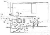
- FIG. 3Ais a side view of another embodiment of the thermal cycling device of the invention, with a sample well tray positioned outside of the device;
- FIG. 3Bis a side view of the device of FIG. 3A, with the sample well tray inserted into the device;
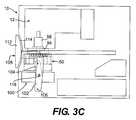
- FIG. 3Cis a side view of the device of FIG. 3A, with the sample well tray inserted into the device and a sample block assembly in an upward position for engaging the sample well tray;
- FIG. 4Ais side view of yet another embodiment of the thermal cycling device of the invention, with the sample well tray positioned outside of the device;
- FIG. 4Bis a side view of the device of FIG. 4A, with the sample well tray inserted into the device;
- FIG. 4Cis a side view of the device of FIG. 4A, with the sample well tray inserted into the device and a sample block assembly in an upward position for engaging the sample well tray;
- FIG. 5is a side cross sectional view of a sample well tray holder, used with the present invention, with a sample well tray positioned thereon;
- FIG. 6is a perspective view of one embodiment of a sample block assembly used in the device of the invention.
- a thermal cycling devicemay perform nucleic acid amplification on a plurality of biological samples positioned in a sample well tray.
- the thermal cycling deviceincludes a sample block assembly, an optical detection system positioned above the sample block assembly, and a sample well tray holder with a tray-receiving region configured to hold the sample well tray.
- the sample block assemblyis adapted for movement between a first position permitting the translation of the sample well tray into alignment with the sample block assembly, and a second position, upward relative to the first position, where the sample block assembly contacts the sample well tray.
- the thermal cycling devicemay also include a positioning mechanism for translating the sample block between the first and second positions.
- the thermal cycling device 10 for performing nucleic acid amplification on a plurality of biological samplesincludes one or more of: a sample block assembly 50 ; an optical detection system 12 for detecting the characteristics of the samples positioned in a sample well tray 14 ; a sample well tray holder 30 ; and a positioning mechanism 70 connected to the sample block assembly, the positioning mechanism being configured to impart vertical movement on the sample block assembly.
- the thermal cycling deviceis typically configured to perform nucleic acid amplification.
- One common method of performing nucleic acid amplification of biological samplesis polymerase chain reaction (PCR).
- PCRpolymerase chain reaction
- Various PCR methodsare known in the art, as described in, for example, U.S. Pat. Nos. 5,928,907 and 6,015,674 to Woudenberg et al., the complete disclosures of which are hereby incorporated by reference for any purpose.
- Other methods of nucleic acid amplificationinclude, for example, ligase chain reaction, oligonucleotide litigations assay, and hybridization assay. These and other methods are described in greater detail in U.S. Pat. Nos. 5,928,907 and 6,015,674.
- the thermal cycling deviceperforms real-time detection of the nucleic acid amplification of the samples during thermal cycling.
- Real-time detection systemsare known in the art, as also described in greater detail in, for example, U.S. Pat. Nos. 5,928,907 and 6,015,674 to Woudenberg et al., incorporated herein above.
- various characteristics of the samplesare detected during the thermal cycling in a manner known in the art. Real-time detection permits more accurate and efficient detection and monitoring of the samples during the nucleic acid amplification.
- the thermal cycling deviceincludes an optical detection system.
- an optical detection system 12is positioned above the sample block assembly 50 .
- the optical detection system 12is configured to detect and monitor the characteristics of the samples in the sample well tray 14 in real-time during the thermal cycling. Suitable structures and methods for the optical detection system 12 are well known in the art.
- the optical detection systemmay use any known structure or method.
- the optical detection systemwould include a quartz bulb with a CCD camera, in a manner known in the art.
- the optical detection systemmay include a fluorescence based system with a lens and a fiber optics for each cable as described in U.S. Pat. Nos.
- the optical detection systemmay include any known system using a single light source for each sample well, in a manner known in the art.
- the optical detection systemmay include any other type suitable for use with the thermal cycling device of the present invention.
- optical detection system 12is substantially stationarily mounted in the thermal cycling device.
- the optical detection systemcan be configured so that the optical detection system remains substantially stationary during insertion of a sample well tray holder and sample well tray into the thermal cycling device, during thermal cycling of the sample well tray, during removal of the sample well tray holder and sample well tray from the thermal cycling device, and at all stages in between the above steps. By remaining substantially stationary, the optical system reduces the potential for misalignment of the optical components.
- substantially stationarydoes not mean that the optical detection system is completely stationary, rather, the term includes any vibrations or movements caused by normal operation of the thermal cycling device.
- the thermal cycling devicemay be configured for use with any type of sample well tray, including, for example, 96-well sample well trays, 384-well sample trays, and microcard sample trays.
- sample well trayincluding, for example, 96-well sample well trays, 384-well sample trays, and microcard sample trays.
- the size and shape of these sample well traysare well known in the art. Examples of 96-well sample well trays suitable for use in the present invention are described in WO 00/25922 to Moring et al., the complete disclosure of which is hereby incorporated by reference for any purpose.
- sample well trays of the microcard type suitable for use in the present inventionare described in WO 01/28684 to Frye et al., the complete disclosure of which is hereby incorporated by reference for any purpose, WO97/36681 to Woudenberg et al., the complete disclosure of which is hereby incorporated by reference for any purpose, U.S. application Ser. No. 09/897,500, filed Jul. 3, 2001, assigned to the assignee of the present invention, the complete disclosure of which is hereby incorporated by reference for any purpose, and U.S. application Ser. No. 09/977,225, filed Oct. 16, 2001, assigned to the assignee of the present application, the complete disclosure of which is hereby incorporated by reference for any purpose.
- sample well trayshaving any number of sample wells and sample well sizes may also be used with the thermal cycling device of the present invention.
- the volume of the sample wellsmay vary anywhere from about 0.01 ⁇ l to thousands of microliters ( ⁇ l), with a volume between 10 to 500 ⁇ l being typical.
- the sample well tray 14can include a rectangular top portion 16 having a top surface 18 and bottom surface 24 .
- the top surface 18defines openings for a plurality of sample wells 20 of any known size and shape.
- the sample well trayincludes ninety-six sample wells positioned in a well-known 8 ⁇ 12 array.
- the top portion 16 of the sample well trayis rectangular.
- the sample wellsare conical shape recesses extending downwardly from the top surface 18 in a known manner.
- Each sample wellincludes a sample well bottom surface 22 for engaging with corresponding recesses in the sample block assembly 50 . It is well understood that any type of sample well configuration may be used with the present invention, including for example, a 384-well sample well tray and a microcard type sample tray.
- the thermal cycling devicecan include a sample well tray holder having a tray-receiving region configured to hold the sample well tray.
- the sample well tray holdercan be configured to translate the sample well tray into alignment with a sample block assembly.
- the sample well tray holderis generally designated by reference number 30 .
- the sample well tray holderis configured so that the sample well tray may be supported thereon, particularly during insertion of the sample well tray into the thermal cycling device, and during removal of the sample well tray from the thermal cycling device.
- the sample well tray holder 30is generally rectangular in shape.
- the sample well tray holder 30includes a top surface 32 and a side surface 34 that extends around the periphery of the sample well tray holder.
- the side surface in the front of the deviceis designated by reference number 36 .
- the sample well tray holderfurther includes a tray-receiving region configured to hold a sample well tray.
- the tray-receiving regionis defined by a downwardly projecting holder structure 38 in the top surface 32 .
- the downwardly projecting holder structure 38is positioned on a first recessed portion 40 of the top surface 32 .
- the downwardly projecting holder structure 38includes a horizontally projecting annular projection 42 for engaging the top surface of the first recessed portion 40 of the top surface 32 .
- the downwardly projecting holder structure 38further comprises a projection 44 that slopes inwardly.
- the inside of the projection 44defines a rectangular opening or recess slightly smaller than the sample well tray 16 .
- the rectangular opening or recessis dimensioned to receive a sample well tray.
- the projection 44is dimensioned so that the bottom surface 24 of the sample well tray may rest on the top surface of the projection 44 , as shown in FIG. 5 .
- the projecting holder structuremay be shaped to be angled inwardly in order to ease the removal of the sample well tray from the sample well tray holder.
- the sample well tray holder 30 and sample well tray 14are dimensioned so that they are capable of passing between the optical detection system 12 and the sample block assembly 50 without interference during insertion into and removal from the thermal cycling device.
- the sample well trayis configured so that it can horizontally translate into and out of the thermal cycling device on the sample well tray holder.
- bearing surfacesmay be provided on the sample well tray holder and/or thermal cycling device.
- the sample well tray holdermay be horizontally translated either manually or automatically.
- the thermal cycling devicecan include a sample block assembly configured to receive the sample well tray thereon.
- a sample block assemblyis generally designated by reference number 50 .
- the sample block assembly shown in FIG. 6is by way of example only, and the invention is not limited to the sample block assembly shown in FIG. 6 .
- the sample block assembly shown in FIG. 6includes a sample block 58 and a heat sink 56 .
- Sample blocksare well known in the art. Sample blocks may be made of any suitable material, such as aluminum.
- the sample block assemblytypically includes at least one heating element. In one embodiment, the at least one heating element includes a peltier heater.
- the sample block 58 shown in FIG. 6includes a top surface 54 with a plurality of recess 52 on the top surface.
- the recessesare arranged to correspond to the sample wells of the sample well tray.
- the sample block assemblyincludes ninety-six recesses for engaging with a 96-well sample well tray.
- the sample block assemblycan have any number of recesses.
- the number of recessescan equal the number of sample wells.
- the sample block assemblywould typically have at least 384 recesses.
- the sample blockneed not have recesses.
- Heat sink 56may be any known type of heat sink.
- a convection unitsuch as a fan may be positioned adjacent the sample block assembly.
- the convection unitcomprises a fan 66 positioned below the sample block assembly 50 .
- the fan 66creates a flow of cooling air against the heat sink 56 in order to cool the sample block.
- the fanmay be used with a heater in order to create a flow of hot air against the heat sink in order to heat the sample block.
- the fanis mounted so that it moves vertically with the sample block assembly. In other embodiments, the fan may be stationarily mounted in the thermal cycling device.
- the thermal cycling devicecan include a positioning mechanism connected to the sample block assembly, the positioning mechanism being configured to vertically translate the sample block assembly between a first or “downward” position and a second or “upward” position.
- the positioning mechanismcan be configured to translate the sample block assembly between the first position, where the sample block assembly permits the translation of the sample well tray into alignment with the sample block assembly, and the second position, upward relative to the first position, where the sample block assembly contacts the sample well tray.
- FIGS. 1 and 2 A- 2 CAn embodiment of the positioning mechanism is illustrated in FIGS. 1 and 2 A- 2 C.
- the positioning mechanismis generally designated by reference number 70 .
- the positioning mechanismis connected to the sample block assembly 50 .
- the positioning mechanismallows insertion and removal of the sample well tray by moving the sample block assembly in the vertical direction.
- FIGS. 2A and 2Bshow the downward or “first” position of the sample block assembly. In the downward position, a gap is created between the top of the sample block assembly 50 and a bottom portion 94 of the optical detection system of sufficient size so that the sample well tray holder and sample well tray may be inserted therebetween. In the first position, the sample block is “away” from the optical detection system.
- the sample block assembly 50In a second or “upward” position shown in FIG. 2C, the sample block assembly 50 is vertically upward relative to the downward or “first” position. In the upward position, the top surface 54 of the sample block 58 presses against the bottom of the sample well tray 14 so that the recesses 52 mate with the sample well bottom surfaces 22 . In various embodiments using a microcard, a top surface of the sample block can press against a bottom surface of the microcard. In the second position, the sample block is “toward” the optical detection system. The sample block assembly is adapted for movement toward and away from the optical detection system along a predetermined vertical path.
- the positioning mechanism 70includes a plurality of links.
- the arrangement of links shown in FIGS. 1 and 2 A- 2 Cis by way of example only.
- the plurality of linksincludes a first link 78 as shown in FIGS. 2A-2C.
- the first link 78is shown as being in the shape of a connecting rod, however, the first link may have any number of different shapes.
- First link 78includes a first end 80 rotatably connected to a motor 72 at a pivot point 74 .
- Motor 72can be any known type of motor that is capable of imparting a translational or rotational force on the first link 78 .
- the motorcauses pivot point 74 of the first end 80 to revolve around a central axis 76 of the motor. The revolution of the first end 80 about the central axis of the motor causes the first link to translate.
- a second end 82 of the first linkis rotatably connected to a first end of a second link 84 at pivot point 88 .
- the second linkhas a second end rotatably connected to stationary pivot point 86 .
- the second link 84pivots about stationary pivot point 86 when the motor causes movement of the first link 78 .
- the second end 82 of the first linkis rotatably connected to a first end of a third link 90 at pivot point 88 .
- the second end of the third link 90is rotatably connected to the sample block assembly at pivot point 92 .
- the positioning mechanismis connected to the sample block assembly by, for example, a pin at pivot point 92 .
- the positioning mechanismcauses the sample block assembly to move vertically from the downward or “first” position shown in FIGS. 2A and 2B to the upward or “second” position shown in FIG. 2 C. It should be understood that the positioning mechanism of FIGS. 2A-2C is by way of example only.
- the positioning mechanism 70may include two sets of links, one on each lateral side of the sample block assembly.
- the second set of linksis a mirror image of the first set of links.
- the second set of linksincludes first link (not shown), second link 84 ′, and third link 90 ′.
- an individual motormay be utilized for each of the sets of links, or alternatively, a single motor may be utilized for both sets of links.
- a single set of linksmay be used instead of two sets of links.
- more than two sets of linksmay be used.
- the positioning mechanismmay also include at least one guide member for guiding the sample block assembly in the vertical direction.
- the guide membercan be configured to prevent the sample block assembly from moving in the horizontal direction. Any known type of guide member may be utilized.
- the guide memberincludes a plurality of vertical shafts 96 fixedly attached to the lateral sides of the sample block assembly 50 . As shown in FIG. 1, the vertical shafts are positioned on each lateral side of the sample well tray holder 30 and sample well tray 14 . Each vertical shaft 96 is received within bearing member 98 . Bearing member is stationarily mounted adjacent the optical detection system. Each vertical shaft 96 slides within a corresponding cylindrical opening in the bearing member 98 .
- the bearing members 98 and vertical shafts 96may include any type of known bearing arrangement.
- the vertical shaftcould be stationarily fixed to the thermal cycling device so that the sample block assembly translates vertically relative to the vertical shaft.
- the bearing structureswould be mounted within cylindrical openings in the sample block assembly for receiving the vertical shafts.
- the guide membermay be any other type of known guide member capable of limiting movement of the sample block assembly in the horizontal direction as the sample block assembly is moved in the vertical direction.
- the guide membercould include any type of vertical guiding structure adjacent the sample block assembly. It should be understood that the guide member shown in FIGS. 2A-2C is by way of example only.
- FIGS. 1 and 2 A- 2 CAn operation of the thermal cycling device for the embodiment of FIGS. 1 and 2 A- 2 C is further described below.
- a sample well tray 14is placed in the sample well tray holder.
- the sample well traycan be dropped into the recess defined by downwardly projecting holder structure 38 shown in FIG. 5 .
- the sample well tray 14may be placed in the sample well tray holder 30 either manually or robotically.
- the sample block assembly 50is in a downward or “first” position so that a gap is created between the optical detection system 12 and the uppermost surface of the sample block 58 .
- the gap that is createdis larger than the vertical dimension of the sample well tray holder 30 and sample well tray 14 .
- the sample well tray holder 30is horizontally translated into the thermal cycling device 10 until the sample well tray reaches a position where the sample wells of the sample well tray align with the recesses 52 of the sample block 58 .
- the horizontal translationmay be caused by an operator or a robot pressing on the sample well tray.
- the sample well tray holder 30can be horizontally translated until each of the ninety-six sample wells align with a corresponding recess 52 in the sample block 58 .
- FIG. 2Bshows the sample well tray holder 30 and sample well tray 14 in the position where the sample wells 20 are aligned with corresponding recesses in the sample block 58 .
- the sample block assembly 50can remain in the downward position until the sample well tray is fully inserted into the thermal cycling device and aligned.
- the motor 72can be actuated to begin a revolution of the first end 80 of the first link 78 .
- the pivot point 88is moved leftward as shown in FIG. 2C, and the pivot point 92 of the second end of the third link imparts an upward force on the sample block assembly 50 .
- the sample block assembly 50is moved upward so that the top surface 54 of the sample block firmly contacts the bottom surface of the sample well tray 14 .
- the sample block assembly 50In the upward position (also referred to as the “second position”) shown in FIG. 2C, the sample block assembly 50 is firmly positioned against the sample well tray 14 so that the sample wells 22 are seated against the sample block.
- the thermal cycling device 10is now ready for thermal cycling processes.
- the sample well tray 14can be removed by actuating the motor so that the sample block assembly 50 moves to a downward position (as shown in FIG. 2 B), and then horizontally translating the sample well tray holder 30 and sample well tray 14 to the position shown in FIG. 2 A. The sample well tray 14 may then be removed from the sample well tray holder 30 .
- the amount of vertical displacement of the sample block assembly 50 between the downward (“first”) and upward (“second”) positionsdepends on the specific application, the type and size of sample well tray that is utilized, and other practical concerns. For example, in an application for use with a 96-well sample well tray, the amount of vertical displacement would typically be between about 0.5 to 1.5 inches, but it could be much greater or much less. In an application with a 384-well sample tray having smaller sample wells, or a microcard, the amount of vertical displacement of the sample block assembly may be less. For practical purposes however, it may also be desirable to vertically displace the sample block assembly a much greater distance in order to provide better access to the inside of the device for inspection or maintenance.
- the optical detection system 12can be mounted in a substantially stationary manner in the thermal cycling device during insertion and removal of the sample well tray to and from the thermal cycling device, during thermal cycling, and during all steps therebetween.
- the plurality of linkscomprises a first link and a second link.
- the first linkhas a first end rotatably connected to a stationary pivot point.
- the first linkalso has a second end comprising a handle for manual manipulation of the first link.
- the second linkhas a first end rotatably connected to a pivot point on the first link.
- the second linkalso has a second end rotatably connected to the sample block assembly.
- the positioning mechanismis generally designated by the reference number 100 in FIGS. 3A-3C.
- the positioning mechanismincludes a plurality of links such as first link 102 and second link 104 .
- the first link 102has a first end rotatably connected to a stationary pivot point 106 and a second end defining a handle 108 for manual manipulation of the first link.
- the first link 102is in the shape of a connecting rod with a bend as shown in FIG. 3 A.
- the handle 108 of the first link 102defines a door 112 corresponding to an opening 114 in the thermal cycling device.
- the door 112is configured to cover the opening 114 in the thermal cycling device when the handle is actuated in a manner described below.
- the dooris shown having an arcuate shape on the inner surface, any other suitable shape is also acceptable.
- the second link 104has a first end rotatably connected to a pivot point 118 positioned on first link 102 .
- the second link 104has a second end rotatably connected to the sample block assembly 50 at pivot point 120 .
- FIG. 3Ashows the sample well tray holder 30 and sample well tray 14 in an outward position.
- the sample block assembly 50is in the downward or “first” position.
- the sample well tray holder 30is then inserted into the thermal cycling device 10 by translating in the horizontal direction until the sample well tray 14 reaches its proper aligned position (shown in FIG. 3B) between the optical detection system and the sample block assembly.
- the handle 108may be rotated robotically.
- the clockwise rotation (in reference to FIGS. 3A-3C) of the first link 102results in the pivot point 118 moving upward, thereby causing the pivot point 120 on the second link 104 to move upward.
- the upward movement of the second linkresults in translation of the sample block assembly 50 in an upward vertical direction to an upward or “second” position (shown in FIG. 3 C).
- the positioning mechanismis configured so that the door 112 is fully closed as shown in FIG. 3C when the top surface of the sample block firmly contacts the sample well tray.
- the handle 108may be rotated counterclockwise, thereby translating the sample block assembly 50 back to the downward position shown in FIG. 3 B.
- the sample well tray holdercan then be slid from the thermal cycling device and returned to the position shown in FIG. 3A, and the sample well tray 14 may be removed from the sample well tray holder.
- the plurality of linkscan comprise a first link and a second link.
- the first linkis rotatably connected to a stationary pivot point.
- the first linkhas a first end rotatably connected to the second link and a second end comprising a handle for manual manipulation of the first link.
- the second linkhas a first end rotatably connected to the first end of the first link and a second end rotatably connected to the sample block assembly.
- the positioning mechanism 130includes a plurality of links such as first link 132 and second link 134 .
- first link 132is rotatably connected to a stationary pivot point 136 .
- the first link 132has a first end rotatably connected to the second link 134 at a pivot point 138 .
- the first linkincludes a second end comprising a handle 140 for manual or automatic manipulation of the first link 132 .
- the second link 134includes a first end rotatably connected to the first end of the first link at pivot point 138 .
- the second link 134further includes a second end rotatably connected to the sample block assembly 50 at pivot point 142 .
- the first link 132includes a first segment 144 and a second segment 146 .
- the first segment 144 and second segment 146 of the first linkare substantially perpendicular to each other. This angle is by way of example only, as the linkages may have various configurations.
- FIG. 4Ashows the sample well tray holder 30 and sample well tray 14 in an outward position.
- the sample block assembly 50is in the downward or “first” position.
- the sample well tray holder 30is then inserted into the thermal cycling device 10 by translating in the horizontal direction until the sample well tray reaches its proper aligned position (shown in FIG. 4 B).
- FIG. 4Cshows the sample block assembly in the upward or “second” position.
- the handle 104may be rotated clockwise, thereby translating the sample block assembly 50 back to the downward position as shown in FIG. 4 B.
- the sample well tray holder 30can then be slid from the thermal cycling device and returned to the position shown in FIG. 4A, and the sample well tray 14 may be removed from the sample well tray holder.
- sample block assembly positioning mechanisms shown in the figuresare provided for purposes of example only. Other positioning mechanisms could be, for example, a hydraulic, a spring, a lever, a cam, a solenoid, or any other suitable motion-producing device.
- the present inventionincludes a method of performing nucleic acid amplification on a plurality of biological samples positioned in a sample well tray in a thermal cycling device.
- the methodincludes the step of placing the sample well tray into a sample well tray holder.
- the sample well tray 14 shown in the figuresis configured for placement into a corresponding recess in the sample well tray holder 30 .
- the methodfurther includes the step of translating the sample well tray holder and sample well tray into the thermal cycling device until the sample well tray is aligned with a sample block assembly positioned beneath the sample well tray.
- the translation of the sample well tray holderis in the horizontal direction.
- the aligned positionis shown for example in FIG. 2 B.
- the methodfurther includes the step of translating the sample block assembly from a first position to a second position.
- the translation of the sample block assemblyis in the vertical direction.
- the sample block assemblypermits the sample well tray to translate into alignment with the sample block assembly.
- the first position of the sample block assembly 50is shown for example in FIG. 2 B.
- the sample block assemblyis positioned vertically upward relative to the first position in order to contact the sample block assembly to the sample well tray.
- the second position of the sample block assembly 50is shown for example in FIG. 2 C.
- the methodfurther comprises thermally cycling the device while simultaneously optically detecting the samples.
- An optical detection system 12is positioned within the thermal cycling device 10 for detecting the characteristics of the sample.
- the methodfurther comprises translating the sample block assembly from the second position to the first position.
- the methodcomprises the step of removing the sample well tray from the thermal cycling device.
- the optical detection systemremains substantially stationary throughout the above steps.
- thermal cycling devicecould be configured to handle several sample well trays, e.g., positioned side by side. Such an arrangement could include a corresponding optical system and sample block.
Landscapes
- Chemical & Material Sciences (AREA)
- Health & Medical Sciences (AREA)
- Chemical Kinetics & Catalysis (AREA)
- Life Sciences & Earth Sciences (AREA)
- Clinical Laboratory Science (AREA)
- Organic Chemistry (AREA)
- Biochemistry (AREA)
- General Health & Medical Sciences (AREA)
- Molecular Biology (AREA)
- Proteomics, Peptides & Aminoacids (AREA)
- Engineering & Computer Science (AREA)
- Zoology (AREA)
- Wood Science & Technology (AREA)
- Biophysics (AREA)
- Microbiology (AREA)
- Immunology (AREA)
- Biotechnology (AREA)
- Bioinformatics & Cheminformatics (AREA)
- General Engineering & Computer Science (AREA)
- Analytical Chemistry (AREA)
- Genetics & Genomics (AREA)
- Physics & Mathematics (AREA)
- Apparatus Associated With Microorganisms And Enzymes (AREA)
Abstract
Description
Claims (35)
Priority Applications (10)
| Application Number | Priority Date | Filing Date | Title |
|---|---|---|---|
| US10/058,927US6677151B2 (en) | 2002-01-30 | 2002-01-30 | Device and method for thermal cycling |
| CA002473806ACA2473806A1 (en) | 2002-01-30 | 2003-01-28 | Device and method for thermal cycling |
| EP03705761.9AEP1470253B1 (en) | 2002-01-30 | 2003-01-28 | Device and method for thermal cycling |
| PCT/US2003/001061WO2003064697A1 (en) | 2002-01-30 | 2003-01-28 | Device and method for thermal cycling |
| AU2003207550AAU2003207550B2 (en) | 2002-01-30 | 2003-01-28 | Device and method for thermal cycling |
| JP2003564286AJP4125240B2 (en) | 2002-01-30 | 2003-01-28 | Devices and methods for thermal cycling |
| US10/756,219US20040142459A1 (en) | 2002-01-30 | 2004-01-12 | Device and method for thermal cycling |
| US12/406,711US20090176282A1 (en) | 2002-01-30 | 2009-03-18 | Device and Method for Thermal Cycling |
| US13/247,393US8993237B2 (en) | 2002-01-30 | 2011-09-28 | Device and method for thermal cycling |
| US14/635,506US9889448B2 (en) | 2002-01-30 | 2015-03-02 | Device and method for thermal cycling |
Applications Claiming Priority (1)
| Application Number | Priority Date | Filing Date | Title |
|---|---|---|---|
| US10/058,927US6677151B2 (en) | 2002-01-30 | 2002-01-30 | Device and method for thermal cycling |
Related Child Applications (1)
| Application Number | Title | Priority Date | Filing Date |
|---|---|---|---|
| US10/756,219ContinuationUS20040142459A1 (en) | 2002-01-30 | 2004-01-12 | Device and method for thermal cycling |
Publications (2)
| Publication Number | Publication Date |
|---|---|
| US20030143723A1 US20030143723A1 (en) | 2003-07-31 |
| US6677151B2true US6677151B2 (en) | 2004-01-13 |
Family
ID=27609712
Family Applications (5)
| Application Number | Title | Priority Date | Filing Date |
|---|---|---|---|
| US10/058,927Expired - LifetimeUS6677151B2 (en) | 2002-01-30 | 2002-01-30 | Device and method for thermal cycling |
| US10/756,219AbandonedUS20040142459A1 (en) | 2002-01-30 | 2004-01-12 | Device and method for thermal cycling |
| US12/406,711AbandonedUS20090176282A1 (en) | 2002-01-30 | 2009-03-18 | Device and Method for Thermal Cycling |
| US13/247,393Expired - Fee RelatedUS8993237B2 (en) | 2002-01-30 | 2011-09-28 | Device and method for thermal cycling |
| US14/635,506Expired - LifetimeUS9889448B2 (en) | 2002-01-30 | 2015-03-02 | Device and method for thermal cycling |
Family Applications After (4)
| Application Number | Title | Priority Date | Filing Date |
|---|---|---|---|
| US10/756,219AbandonedUS20040142459A1 (en) | 2002-01-30 | 2004-01-12 | Device and method for thermal cycling |
| US12/406,711AbandonedUS20090176282A1 (en) | 2002-01-30 | 2009-03-18 | Device and Method for Thermal Cycling |
| US13/247,393Expired - Fee RelatedUS8993237B2 (en) | 2002-01-30 | 2011-09-28 | Device and method for thermal cycling |
| US14/635,506Expired - LifetimeUS9889448B2 (en) | 2002-01-30 | 2015-03-02 | Device and method for thermal cycling |
Country Status (6)
| Country | Link |
|---|---|
| US (5) | US6677151B2 (en) |
| EP (1) | EP1470253B1 (en) |
| JP (1) | JP4125240B2 (en) |
| AU (1) | AU2003207550B2 (en) |
| CA (1) | CA2473806A1 (en) |
| WO (1) | WO2003064697A1 (en) |
Cited By (41)
| Publication number | Priority date | Publication date | Assignee | Title |
|---|---|---|---|---|
| US20020192716A1 (en)* | 1999-03-19 | 2002-12-19 | Volker Schellenberger | Multi-through hole testing plate for high throughput screening |
| US20040023371A1 (en)* | 2002-07-30 | 2004-02-05 | Adrian Fawcett | Sample block apparatus and method for maintaining a microcard on a sample block |
| US20040037748A1 (en)* | 2002-08-23 | 2004-02-26 | Leila Hasan | Voltage-aided transfer pins |
| US20040142459A1 (en)* | 2002-01-30 | 2004-07-22 | Applera Corporation | Device and method for thermal cycling |
| US20040191924A1 (en)* | 1998-01-12 | 2004-09-30 | Massachusetts Institute Of Technology | Reformatted through-hole arrays |
| US20040208792A1 (en)* | 2002-12-20 | 2004-10-21 | John Linton | Assay apparatus and method using microfluidic arrays |
| US20040265884A1 (en)* | 2003-06-04 | 2004-12-30 | Jochem Knoche | Thermocycler |
| US20050201901A1 (en)* | 2004-01-25 | 2005-09-15 | Fluidigm Corp. | Crystal forming devices and systems and methods for using the same |
| US20050214173A1 (en)* | 2004-01-25 | 2005-09-29 | Fluidigm Corporation | Integrated chip carriers with thermocycler interfaces and methods of using the same |
| US20060030037A1 (en)* | 2004-05-28 | 2006-02-09 | Victor Joseph | Thermo-controllable high-density chips for multiplex analyses |
| US20060094108A1 (en)* | 2002-12-20 | 2006-05-04 | Karl Yoder | Thermal cycler for microfluidic array assays |
| US20070084279A1 (en)* | 2005-10-13 | 2007-04-19 | Chien-Chih Huang | Apparatus and method for controlling micro-fluid temperature |
| US20080003649A1 (en)* | 2006-05-17 | 2008-01-03 | California Institute Of Technology | Thermal cycling system |
| US20080176290A1 (en)* | 2007-01-22 | 2008-07-24 | Victor Joseph | Apparatus for high throughput chemical reactions |
| EP1958695A2 (en) | 2007-02-13 | 2008-08-20 | Eppendorf AG | Cover for an array of reaction containers for a single-step operational mode |
| US20090155855A1 (en)* | 2007-02-13 | 2009-06-18 | Eppendorf Ag | Cover for sample with homogenous pressure application |
| US7604983B2 (en) | 2000-02-18 | 2009-10-20 | Board Of Trustees Of The Leland Stanford Junior University | Apparatus and methods for parallel processing of micro-volume liquid reactions |
| US20100279299A1 (en)* | 2009-04-03 | 2010-11-04 | Helixis, Inc. | Devices and Methods for Heating Biological Samples |
| US20110056661A1 (en)* | 2009-09-01 | 2011-03-10 | Life Technologies Corporation | Thermal Block Assemblies and Instruments Providing Low Thermal Non-Uniformity for Rapid Thermal Cycling |
| US20110057117A1 (en)* | 2009-09-09 | 2011-03-10 | Helixis, Inc. | Optical system for multiple reactions |
| US20110156090A1 (en)* | 2008-03-25 | 2011-06-30 | Lin Charles W C | Semiconductor chip assembly with post/base/post heat spreader and asymmetric posts |
| US8105554B2 (en) | 2004-03-12 | 2012-01-31 | Life Technologies Corporation | Nanoliter array loading |
| US20120177549A1 (en)* | 2009-07-14 | 2012-07-12 | Mantis Deposition Limited | Sample Holder |
| US20120244048A1 (en)* | 2011-03-22 | 2012-09-27 | Teng Ping-Hua | Apparatus for insulated isothermal polymerase chain reaction |
| US20150044726A1 (en)* | 2012-03-09 | 2015-02-12 | Genereach Biotechnology Corp. | Device for controlling thermal convection velocity of biochemical reaction and method for the same |
| WO2014179483A3 (en)* | 2013-05-02 | 2015-04-02 | Bio-Rad Laboratories, Inc. | Drawer handle mechanism |
| US9289769B2 (en) | 2007-02-13 | 2016-03-22 | Eppendorf Ag | Cover for sample with sample-size independent height adjustment |
| US9623415B2 (en) | 2014-12-31 | 2017-04-18 | Click Diagnostics, Inc. | Devices and methods for molecular diagnostic testing |
| USD800331S1 (en) | 2016-06-29 | 2017-10-17 | Click Diagnostics, Inc. | Molecular diagnostic device |
| USD800913S1 (en) | 2016-06-30 | 2017-10-24 | Click Diagnostics, Inc. | Detection window for molecular diagnostic device |
| USD800914S1 (en) | 2016-06-30 | 2017-10-24 | Click Diagnostics, Inc. | Status indicator for molecular diagnostic device |
| US9829696B2 (en) | 2013-05-01 | 2017-11-28 | Bio-Rad Laboratories, Inc. | Adjustable digital microscope display |
| US10195610B2 (en) | 2014-03-10 | 2019-02-05 | Click Diagnostics, Inc. | Cartridge-based thermocycler |
| US10441953B2 (en)* | 2013-11-08 | 2019-10-15 | Biovices Ipr Holdings A/S | Device and method for heating a fluid chamber |
| US10641772B2 (en) | 2015-02-20 | 2020-05-05 | Takara Bio Usa, Inc. | Method for rapid accurate dispensing, visualization and analysis of single cells |
| US10675623B2 (en) | 2016-06-29 | 2020-06-09 | Visby Medical, Inc. | Devices and methods for the detection of molecules using a flow cell |
| US10987674B2 (en) | 2016-04-22 | 2021-04-27 | Visby Medical, Inc. | Printed circuit board heater for an amplification module |
| US11162130B2 (en) | 2017-11-09 | 2021-11-02 | Visby Medical, Inc. | Portable molecular diagnostic device and methods for the detection of target viruses |
| US11193119B2 (en) | 2016-05-11 | 2021-12-07 | Visby Medical, Inc. | Devices and methods for nucleic acid extraction |
| US11460405B2 (en) | 2016-07-21 | 2022-10-04 | Takara Bio Usa, Inc. | Multi-Z imaging and dispensing with multi-well devices |
| USD1055307S1 (en) | 2021-08-13 | 2024-12-24 | Visby Medical, Inc. | Molecular diagnostic device |
Families Citing this family (10)
| Publication number | Priority date | Publication date | Assignee | Title |
|---|---|---|---|---|
| US7133726B1 (en)* | 1997-03-28 | 2006-11-07 | Applera Corporation | Thermal cycler for PCR |
| DE102005027555B3 (en)* | 2005-06-14 | 2006-10-05 | Eppendorf Ag | Thermocycler for carrying out polymerase chain reactions, has thermostatically controlled area, in which reaction vessel is placed, lid being placed over this incorporating an optical unit adjusted using pins on base and sleeves on lid |
| JP5178149B2 (en)* | 2007-10-31 | 2013-04-10 | キヤノン株式会社 | Real-time PCR method and apparatus for target nucleic acid |
| FI20095059A0 (en)* | 2009-01-26 | 2009-01-26 | Wallac Oy | Apparatus and method for optical measurement of samples |
| GB2511692A (en)* | 2009-08-08 | 2014-09-10 | Bibby Scient Ltd | An apparatus for treating a test sample |
| DE102018131127A1 (en)* | 2018-12-06 | 2020-06-10 | Analytik Jena Ag | Automated temperature control device |
| CN119951603A (en)* | 2019-01-30 | 2025-05-09 | 生命技术控股私人有限公司 | Bioanalysis systems and methods |
| EP4314760A4 (en)* | 2021-03-31 | 2025-03-26 | ASP Health Inc. | Benchtop instrument and consumables for sample deposition and staining |
| WO2022251515A2 (en)* | 2021-05-28 | 2022-12-01 | Proof Diagnostics | Device for processing reaction cartridge |
| CN115193504B (en)* | 2022-08-02 | 2023-09-01 | 吴堡县农产品质量安全中心 | Purification workbench for livestock product detection |
Citations (21)
| Publication number | Priority date | Publication date | Assignee | Title |
|---|---|---|---|---|
| US4097116A (en) | 1975-11-10 | 1978-06-27 | Nippon Kogaku K.K. | Microscope stage |
| US4313679A (en) | 1979-11-29 | 1982-02-02 | The United States Of America As Represented By The Secretary Of The Air Force | Test sample support assembly |
| US4577141A (en) | 1983-11-30 | 1986-03-18 | Nippon Kogaku K.K. | System for driving a movable stage |
| EP0311440A2 (en) | 1987-10-09 | 1989-04-12 | Seiko Instruments Inc. | Apparatus for carrying out a liquid reaction |
| US4865461A (en) | 1988-02-25 | 1989-09-12 | Purdue Research Foundation | Apparatus for use in determining a thermal characteristic of a specimen |
| US5416329A (en) | 1990-05-08 | 1995-05-16 | Wallac Oy | Apparatus for counting liquid scintillation samples |
| US5489532A (en) | 1988-05-04 | 1996-02-06 | Charm Sciences, Inc. | Automatic test apparatus for antimicrobial drugs |
| US5616301A (en) | 1993-09-10 | 1997-04-01 | Hoffmann-La Roche Inc. | Thermal cycler |
| WO1997036681A1 (en) | 1996-04-03 | 1997-10-09 | The Perkin-Elmer Corporation | Device and method for multiple analyte detection |
| US5720923A (en) | 1993-07-28 | 1998-02-24 | The Perkin-Elmer Corporation | Nucleic acid amplification reaction apparatus |
| US5736106A (en) | 1995-01-26 | 1998-04-07 | Tosoh Corporation | Thermal cycling reaction apparatus and reactor therefor |
| US5897842A (en) | 1996-05-01 | 1999-04-27 | Visible Genetics Inc. | Method and apparatus for thermal cycling and for automated sample preparation with thermal cycling |
| US5928907A (en) | 1994-04-29 | 1999-07-27 | The Perkin-Elmer Corporation., Applied Biosystems Division | System for real time detection of nucleic acid amplification products |
| US6036920A (en)* | 1996-05-09 | 2000-03-14 | 3-Dimensional Pharmaceuticals, Inc. | Microplate thermal shift assay apparatus for ligand development and multi-variable protein chemistry optimization |
| US6043880A (en) | 1997-09-15 | 2000-03-28 | Becton Dickinson And Company | Automated optical reader for nucleic acid assays |
| WO2000025922A2 (en) | 1998-10-29 | 2000-05-11 | The Perkin-Elmer Corporation | Multi-well microfiltration apparatus |
| US6132996A (en) | 1996-06-17 | 2000-10-17 | The Board Of Trustees Of The Leland Stanford Junior University | Thermocycling apparatus and method |
| US6197572B1 (en) | 1998-05-04 | 2001-03-06 | Roche Diagnostics Corporation | Thermal cycler having an automatically positionable lid |
| US6210958B1 (en) | 1996-11-08 | 2001-04-03 | Eppendorf-Netheler-Hinz, Gbmh | Temperature regulating block with receivers |
| WO2001028684A2 (en) | 1999-10-15 | 2001-04-26 | Pe Corporation (Ny) | System and method for filling a substrate with a liquid sample |
| US6448066B1 (en) | 1998-12-07 | 2002-09-10 | Her Majesty The Queen In Right Of Canada, As Represented By The Minister Of Agriculture And Agri-Food | Rotary thermocycling apparatus |
Family Cites Families (7)
| Publication number | Priority date | Publication date | Assignee | Title |
|---|---|---|---|---|
| US3645690A (en)* | 1968-01-22 | 1972-02-29 | Beckman Instruments Inc | Automated chemical analyzer |
| CA2031912A1 (en)* | 1989-12-22 | 1991-06-23 | Robert Fred Pfost | Heated cover device |
| US5525300A (en)* | 1993-10-20 | 1996-06-11 | Stratagene | Thermal cycler including a temperature gradient block |
| DE29623597U1 (en) | 1996-11-08 | 1999-01-07 | Eppendorf - Netheler - Hinz Gmbh, 22339 Hamburg | Temperature control block with temperature control devices |
| US6719949B1 (en)* | 2000-06-29 | 2004-04-13 | Applera Corporation | Apparatus and method for transporting sample well trays |
| US6514750B2 (en)* | 2001-07-03 | 2003-02-04 | Pe Corporation (Ny) | PCR sample handling device |
| US6677151B2 (en)* | 2002-01-30 | 2004-01-13 | Applera Corporation | Device and method for thermal cycling |
- 2002
- 2002-01-30USUS10/058,927patent/US6677151B2/ennot_activeExpired - Lifetime
- 2003
- 2003-01-28AUAU2003207550Apatent/AU2003207550B2/ennot_activeCeased
- 2003-01-28EPEP03705761.9Apatent/EP1470253B1/ennot_activeExpired - Lifetime
- 2003-01-28WOPCT/US2003/001061patent/WO2003064697A1/enactiveApplication Filing
- 2003-01-28CACA002473806Apatent/CA2473806A1/ennot_activeAbandoned
- 2003-01-28JPJP2003564286Apatent/JP4125240B2/ennot_activeExpired - Lifetime
- 2004
- 2004-01-12USUS10/756,219patent/US20040142459A1/ennot_activeAbandoned
- 2009
- 2009-03-18USUS12/406,711patent/US20090176282A1/ennot_activeAbandoned
- 2011
- 2011-09-28USUS13/247,393patent/US8993237B2/ennot_activeExpired - Fee Related
- 2015
- 2015-03-02USUS14/635,506patent/US9889448B2/ennot_activeExpired - Lifetime
Patent Citations (24)
| Publication number | Priority date | Publication date | Assignee | Title |
|---|---|---|---|---|
| US4097116A (en) | 1975-11-10 | 1978-06-27 | Nippon Kogaku K.K. | Microscope stage |
| US4313679A (en) | 1979-11-29 | 1982-02-02 | The United States Of America As Represented By The Secretary Of The Air Force | Test sample support assembly |
| US4577141A (en) | 1983-11-30 | 1986-03-18 | Nippon Kogaku K.K. | System for driving a movable stage |
| EP0311440A2 (en) | 1987-10-09 | 1989-04-12 | Seiko Instruments Inc. | Apparatus for carrying out a liquid reaction |
| US4865461A (en) | 1988-02-25 | 1989-09-12 | Purdue Research Foundation | Apparatus for use in determining a thermal characteristic of a specimen |
| US5489532A (en) | 1988-05-04 | 1996-02-06 | Charm Sciences, Inc. | Automatic test apparatus for antimicrobial drugs |
| US5416329A (en) | 1990-05-08 | 1995-05-16 | Wallac Oy | Apparatus for counting liquid scintillation samples |
| US6033880A (en) | 1993-07-28 | 2000-03-07 | The Perkin-Elmer Corporation | Nucleic acid amplification reaction apparatus and method |
| US5720923A (en) | 1993-07-28 | 1998-02-24 | The Perkin-Elmer Corporation | Nucleic acid amplification reaction apparatus |
| US5616301A (en) | 1993-09-10 | 1997-04-01 | Hoffmann-La Roche Inc. | Thermal cycler |
| US5795547A (en) | 1993-09-10 | 1998-08-18 | Roche Diagnostic Systems, Inc. | Thermal cycler |
| US5928907A (en) | 1994-04-29 | 1999-07-27 | The Perkin-Elmer Corporation., Applied Biosystems Division | System for real time detection of nucleic acid amplification products |
| US6015674A (en) | 1994-04-29 | 2000-01-18 | Perkin-Elmer Corporation Applied Biosystems Division | Apparatus and method for detecting nucleic acid amplification products |
| US5736106A (en) | 1995-01-26 | 1998-04-07 | Tosoh Corporation | Thermal cycling reaction apparatus and reactor therefor |
| WO1997036681A1 (en) | 1996-04-03 | 1997-10-09 | The Perkin-Elmer Corporation | Device and method for multiple analyte detection |
| US5897842A (en) | 1996-05-01 | 1999-04-27 | Visible Genetics Inc. | Method and apparatus for thermal cycling and for automated sample preparation with thermal cycling |
| US6036920A (en)* | 1996-05-09 | 2000-03-14 | 3-Dimensional Pharmaceuticals, Inc. | Microplate thermal shift assay apparatus for ligand development and multi-variable protein chemistry optimization |
| US6132996A (en) | 1996-06-17 | 2000-10-17 | The Board Of Trustees Of The Leland Stanford Junior University | Thermocycling apparatus and method |
| US6210958B1 (en) | 1996-11-08 | 2001-04-03 | Eppendorf-Netheler-Hinz, Gbmh | Temperature regulating block with receivers |
| US6043880A (en) | 1997-09-15 | 2000-03-28 | Becton Dickinson And Company | Automated optical reader for nucleic acid assays |
| US6197572B1 (en) | 1998-05-04 | 2001-03-06 | Roche Diagnostics Corporation | Thermal cycler having an automatically positionable lid |
| WO2000025922A2 (en) | 1998-10-29 | 2000-05-11 | The Perkin-Elmer Corporation | Multi-well microfiltration apparatus |
| US6448066B1 (en) | 1998-12-07 | 2002-09-10 | Her Majesty The Queen In Right Of Canada, As Represented By The Minister Of Agriculture And Agri-Food | Rotary thermocycling apparatus |
| WO2001028684A2 (en) | 1999-10-15 | 2001-04-26 | Pe Corporation (Ny) | System and method for filling a substrate with a liquid sample |
Non-Patent Citations (3)
| Title |
|---|
| Co-pending application No. 09/897,500, Inventors: Bordenkircher et al., filed Jul. 3, 2001, Title: PCR sample handling device. |
| Co-pending application No. 09/977,225, Inventors: Freudenthal et al., filed Oct. 16, 2001, Title: System for filling substrate chambers with liquid. |
| International Search Report dated Apr. 21, 2003 issued in PCT/US03/01061. |
Cited By (124)
| Publication number | Priority date | Publication date | Assignee | Title |
|---|---|---|---|---|
| US20040191924A1 (en)* | 1998-01-12 | 2004-09-30 | Massachusetts Institute Of Technology | Reformatted through-hole arrays |
| US8029745B2 (en) | 1998-01-12 | 2011-10-04 | Massachusetts Institute Of Technology | Systems for filling a sample array by droplet dragging |
| US20050079105A1 (en)* | 1998-01-12 | 2005-04-14 | Massachusetts Institute Of Technology | Methods for filing a sample array by droplet dragging |
| US7547556B2 (en) | 1998-01-12 | 2009-06-16 | Massachusetts Institute Of Technology | Methods for filing a sample array by droplet dragging |
| US10195579B2 (en) | 1999-03-19 | 2019-02-05 | Life Technologies Corporation | Multi-through hole testing plate for high throughput screening |
| US20020192716A1 (en)* | 1999-03-19 | 2002-12-19 | Volker Schellenberger | Multi-through hole testing plate for high throughput screening |
| US7666360B2 (en) | 1999-03-19 | 2010-02-23 | Biotrove, Inc. | Multi-through hole testing plate for high throughput screening |
| US10378049B2 (en) | 2000-02-18 | 2019-08-13 | The Board Of Trustees Of The Leland Stanford Junior University | Apparatus and methods for parallel processing of microvolume liquid reactions |
| US10227644B2 (en) | 2000-02-18 | 2019-03-12 | The Board Of Trustees Of The Leland Stanford Junior University | Apparatus and methods for parallel processing of microvolume liquid reactions |
| US7604983B2 (en) | 2000-02-18 | 2009-10-20 | Board Of Trustees Of The Leland Stanford Junior University | Apparatus and methods for parallel processing of micro-volume liquid reactions |
| US9518299B2 (en) | 2000-02-18 | 2016-12-13 | The Board Of Trustees Of The Leland Stanford Junior University | Apparatus and methods for parallel processing of micro-volume liquid reactions |
| US8906618B2 (en) | 2000-02-18 | 2014-12-09 | The Board Of Trustees Of The Leland Stanford Junior University | Apparatus and methods for parallel processing of micro-volume liquid reactions |
| US20100311060A1 (en)* | 2000-04-05 | 2010-12-09 | Fluidigm Corporation | Integrated Chip Carriers With Thermocycler Interfaces And Methods Of Using The Same |
| US9623413B2 (en) | 2000-04-05 | 2017-04-18 | Fluidigm Corporation | Integrated chip carriers with thermocycler interfaces and methods of using the same |
| US8993237B2 (en) | 2002-01-30 | 2015-03-31 | Applied Biosystems, Llc | Device and method for thermal cycling |
| US9889448B2 (en)* | 2002-01-30 | 2018-02-13 | Applied Biosystems, Llc | Device and method for thermal cycling |
| US20090176282A1 (en)* | 2002-01-30 | 2009-07-09 | Life Technologies Corporation | Device and Method for Thermal Cycling |
| US20040142459A1 (en)* | 2002-01-30 | 2004-07-22 | Applera Corporation | Device and method for thermal cycling |
| US20150165439A1 (en)* | 2002-01-30 | 2015-06-18 | Applied Biosystems, Llc | Device and method for Thermal Cycling |
| US20090029454A1 (en)* | 2002-07-30 | 2009-01-29 | Applera Corporation | Sample block apparatus and method for maintaining a microcard on a sample block |
| US7452712B2 (en)* | 2002-07-30 | 2008-11-18 | Applied Biosystems Inc. | Sample block apparatus and method of maintaining a microcard on a sample block |
| US8247221B2 (en) | 2002-07-30 | 2012-08-21 | Applied Biosystems, Llc | Sample block apparatus and method for maintaining a microcard on sample block |
| US7858365B2 (en) | 2002-07-30 | 2010-12-28 | Applied Biosystems, Llc | Sample block apparatus and method for maintaining a microcard on a sample block |
| US10253361B2 (en) | 2002-07-30 | 2019-04-09 | Applied Biosystems, Llc | Sample block apparatus and method for maintaining a microcard on a sample block |
| US20040023371A1 (en)* | 2002-07-30 | 2004-02-05 | Adrian Fawcett | Sample block apparatus and method for maintaining a microcard on a sample block |
| US20090054266A1 (en)* | 2002-08-23 | 2009-02-26 | Biotrove, Inc. | Microfluidic transfer pin |
| US8277753B2 (en) | 2002-08-23 | 2012-10-02 | Life Technologies Corporation | Microfluidic transfer pin |
| US20040037748A1 (en)* | 2002-08-23 | 2004-02-26 | Leila Hasan | Voltage-aided transfer pins |
| US8685340B2 (en) | 2002-08-23 | 2014-04-01 | Life Technologies Corporation | Microfluidic transfer pin |
| US7682565B2 (en) | 2002-12-20 | 2010-03-23 | Biotrove, Inc. | Assay apparatus and method using microfluidic arrays |
| US9428800B2 (en) | 2002-12-20 | 2016-08-30 | Life Technologies Corporation | Thermal cycling apparatus and method |
| US20040208792A1 (en)* | 2002-12-20 | 2004-10-21 | John Linton | Assay apparatus and method using microfluidic arrays |
| US8697452B2 (en) | 2002-12-20 | 2014-04-15 | Life Technologies Corporation | Thermal cycling assay apparatus and method |
| US20060094108A1 (en)* | 2002-12-20 | 2006-05-04 | Karl Yoder | Thermal cycler for microfluidic array assays |
| US20110003699A1 (en)* | 2002-12-20 | 2011-01-06 | Biotrove, Inc. | Thermal Cycler for Microfluidic Array Assays |
| US20090062152A1 (en)* | 2002-12-20 | 2009-03-05 | Biotrove, Inc. | Thermal cycling apparatus and method |
| US20090062134A1 (en)* | 2002-12-20 | 2009-03-05 | Biotrove, Inc. | Assay imaging apparatus and methods |
| US20040265884A1 (en)* | 2003-06-04 | 2004-12-30 | Jochem Knoche | Thermocycler |
| US7030340B2 (en)* | 2003-06-04 | 2006-04-18 | Siemens Aktiengesellschaft | Thermocycler |
| US8105553B2 (en) | 2004-01-25 | 2012-01-31 | Fluidigm Corporation | Crystal forming devices and systems and methods for using the same |
| US20050214173A1 (en)* | 2004-01-25 | 2005-09-29 | Fluidigm Corporation | Integrated chip carriers with thermocycler interfaces and methods of using the same |
| US7704735B2 (en) | 2004-01-25 | 2010-04-27 | Fluidigm Corporation | Integrated chip carriers with thermocycler interfaces and methods of using the same |
| US20050201901A1 (en)* | 2004-01-25 | 2005-09-15 | Fluidigm Corp. | Crystal forming devices and systems and methods for using the same |
| US20070196912A1 (en)* | 2004-01-25 | 2007-08-23 | Fluidigm Corporation | Integrated chip carriers with thermocycler interfaces and methods of using the same |
| US8105824B2 (en) | 2004-01-25 | 2012-01-31 | Fluidigm Corporation | Integrated chip carriers with thermocycler interfaces and methods of using the same |
| US9266108B2 (en) | 2004-03-12 | 2016-02-23 | Life Technologies Corporation | Nanoliter array loading |
| US10065189B2 (en) | 2004-03-12 | 2018-09-04 | Life Technologies Corporation | Nanoliter array loading |
| US8105554B2 (en) | 2004-03-12 | 2012-01-31 | Life Technologies Corporation | Nanoliter array loading |
| US10974247B2 (en) | 2004-03-12 | 2021-04-13 | Life Technologies Corporation | Nanoliter array loading |
| US8545772B2 (en) | 2004-03-12 | 2013-10-01 | Life Technologies Corporation | Nanoliter array loading |
| US10718014B2 (en) | 2004-05-28 | 2020-07-21 | Takara Bio Usa, Inc. | Thermo-controllable high-density chips for multiplex analyses |
| US7833709B2 (en) | 2004-05-28 | 2010-11-16 | Wafergen, Inc. | Thermo-controllable chips for multiplex analyses |
| US9909171B2 (en) | 2004-05-28 | 2018-03-06 | Takara Bio Usa, Inc. | Thermo-controllable high-density chips for multiplex analyses |
| US20060030035A1 (en)* | 2004-05-28 | 2006-02-09 | Victor Joseph | Thermo-controllable chips for multiplex analyses |
| US20060030037A1 (en)* | 2004-05-28 | 2006-02-09 | Victor Joseph | Thermo-controllable high-density chips for multiplex analyses |
| US9228933B2 (en) | 2004-05-28 | 2016-01-05 | Wafergen, Inc. | Apparatus and method for multiplex analysis |
| US20100233698A1 (en)* | 2004-05-28 | 2010-09-16 | Wafergen, Inc. | Apparatus and method for multiplex analysis |
| US20070084279A1 (en)* | 2005-10-13 | 2007-04-19 | Chien-Chih Huang | Apparatus and method for controlling micro-fluid temperature |
| US8003370B2 (en) | 2006-05-17 | 2011-08-23 | California Institute Of Technology | Thermal cycling apparatus |
| US20080003649A1 (en)* | 2006-05-17 | 2008-01-03 | California Institute Of Technology | Thermal cycling system |
| US8232091B2 (en) | 2006-05-17 | 2012-07-31 | California Institute Of Technology | Thermal cycling system |
| US9316586B2 (en) | 2006-05-17 | 2016-04-19 | California Institute Of Technology | Apparatus for thermal cycling |
| US8008046B2 (en) | 2006-05-17 | 2011-08-30 | California Institute Of Technology | Thermal cycling method |
| US20090275113A1 (en)* | 2006-05-17 | 2009-11-05 | California Institute Of Technology | Thermal cycling apparatus |
| US20090275014A1 (en)* | 2006-05-17 | 2009-11-05 | California Institute Of Technology Office Of Technology Transfer | Thermal cycling method |
| US8252581B2 (en) | 2007-01-22 | 2012-08-28 | Wafergen, Inc. | Apparatus for high throughput chemical reactions |
| US11643681B2 (en) | 2007-01-22 | 2023-05-09 | Takara Bio Usa, Inc. | Apparatus for high throughput chemical reactions |
| US9132427B2 (en) | 2007-01-22 | 2015-09-15 | Wafergen, Inc. | Apparatus for high throughput chemical reactions |
| US20080176290A1 (en)* | 2007-01-22 | 2008-07-24 | Victor Joseph | Apparatus for high throughput chemical reactions |
| US9951381B2 (en) | 2007-01-22 | 2018-04-24 | Takara Bio Usa, Inc. | Apparatus for high throughput chemical reactions |
| US20080318280A1 (en)* | 2007-02-13 | 2008-12-25 | Eppendorf Ag | Cover for an array of reaction vessels for one-step operation modus |
| US8492137B2 (en) | 2007-02-13 | 2013-07-23 | Eppendorf Ag | Cover for sample with homogenous pressure application |
| US9289769B2 (en) | 2007-02-13 | 2016-03-22 | Eppendorf Ag | Cover for sample with sample-size independent height adjustment |
| EP1958695A2 (en) | 2007-02-13 | 2008-08-20 | Eppendorf AG | Cover for an array of reaction containers for a single-step operational mode |
| US20090155855A1 (en)* | 2007-02-13 | 2009-06-18 | Eppendorf Ag | Cover for sample with homogenous pressure application |
| US20110156090A1 (en)* | 2008-03-25 | 2011-06-30 | Lin Charles W C | Semiconductor chip assembly with post/base/post heat spreader and asymmetric posts |
| US20100279299A1 (en)* | 2009-04-03 | 2010-11-04 | Helixis, Inc. | Devices and Methods for Heating Biological Samples |
| US20120177549A1 (en)* | 2009-07-14 | 2012-07-12 | Mantis Deposition Limited | Sample Holder |
| WO2011028834A3 (en)* | 2009-09-01 | 2011-07-07 | Life Technologies Corporation | Thermal block assemblies and instruments providing low thermal non-uniformity for rapid thermal cycling |
| US20110056661A1 (en)* | 2009-09-01 | 2011-03-10 | Life Technologies Corporation | Thermal Block Assemblies and Instruments Providing Low Thermal Non-Uniformity for Rapid Thermal Cycling |
| US10049895B2 (en) | 2009-09-01 | 2018-08-14 | Life Technologies Corporation | Thermal block assemblies and instruments providing low thermal non-uniformity for rapid thermal cycling |
| US8987685B2 (en) | 2009-09-09 | 2015-03-24 | Pcr Max Limited | Optical system for multiple reactions |
| US20110057117A1 (en)* | 2009-09-09 | 2011-03-10 | Helixis, Inc. | Optical system for multiple reactions |
| US8574516B2 (en)* | 2011-03-22 | 2013-11-05 | Genereach Biotechnology Corp. | Apparatus for insulated isothermal polymerase chain reaction |
| US20120244048A1 (en)* | 2011-03-22 | 2012-09-27 | Teng Ping-Hua | Apparatus for insulated isothermal polymerase chain reaction |
| US9505004B2 (en)* | 2012-03-09 | 2016-11-29 | Genereach Biotechnology Corp. | Device for controlling thermal convection velocity of biochemical reaction and method for the same |
| US20150044726A1 (en)* | 2012-03-09 | 2015-02-12 | Genereach Biotechnology Corp. | Device for controlling thermal convection velocity of biochemical reaction and method for the same |
| US9829696B2 (en) | 2013-05-01 | 2017-11-28 | Bio-Rad Laboratories, Inc. | Adjustable digital microscope display |
| US11592658B2 (en) | 2013-05-01 | 2023-02-28 | Bio-Rad Laboratories, Inc. | Adjustable digital microscope display |
| US12085705B2 (en) | 2013-05-01 | 2024-09-10 | Bio-Rad Laboratories, Inc. | Adjustable digital microscope display |
| US9885862B2 (en) | 2013-05-01 | 2018-02-06 | Bio-Rad Laboratories, Inc. | Adjustable digital microscope display |
| US10802264B2 (en) | 2013-05-01 | 2020-10-13 | Bio-Rad Laboratories, Inc. | Adjustable digital microscope display |
| WO2014179483A3 (en)* | 2013-05-02 | 2015-04-02 | Bio-Rad Laboratories, Inc. | Drawer handle mechanism |
| US10441953B2 (en)* | 2013-11-08 | 2019-10-15 | Biovices Ipr Holdings A/S | Device and method for heating a fluid chamber |
| US10960399B2 (en) | 2014-03-10 | 2021-03-30 | Visby Medical, Inc. | Cartridge-based thermocycler |
| US10195610B2 (en) | 2014-03-10 | 2019-02-05 | Click Diagnostics, Inc. | Cartridge-based thermocycler |
| US9623415B2 (en) | 2014-12-31 | 2017-04-18 | Click Diagnostics, Inc. | Devices and methods for molecular diagnostic testing |
| US12138624B2 (en) | 2014-12-31 | 2024-11-12 | Visby Medical, Inc. | Devices and methods for molecular diagnostic testing |
| US10456783B2 (en) | 2014-12-31 | 2019-10-29 | Click Diagnostics, Inc. | Devices and methods for molecular diagnostic testing |
| US10525469B2 (en) | 2014-12-31 | 2020-01-07 | Visby Medical, Inc. | Devices and methods for molecular diagnostic testing |
| US11273443B2 (en) | 2014-12-31 | 2022-03-15 | Visby Medical, Inc. | Devices and methods for molecular diagnostic testing |
| US11167285B2 (en) | 2014-12-31 | 2021-11-09 | Visby Medical, Inc. | Devices and methods for molecular diagnostic testing |
| US10124334B2 (en) | 2014-12-31 | 2018-11-13 | Click Diagnostics, Inc. | Devices and methods for molecular diagnostic testing |
| US10112197B2 (en) | 2014-12-31 | 2018-10-30 | Click Diagnostics, Inc. | Devices and methods for molecular diagnostic testing |
| US10112196B2 (en) | 2014-12-31 | 2018-10-30 | Click Diagnostics, Inc. | Devices and methods for molecular diagnostic testing |
| US10052629B2 (en) | 2014-12-31 | 2018-08-21 | Click Diagnostics, Inc. | Devices and methods for molecular diagnostic testing |
| US10279346B2 (en) | 2014-12-31 | 2019-05-07 | Click Diagnostics, Inc. | Devices and methods for molecular diagnostic testing |
| US11125752B2 (en) | 2015-02-20 | 2021-09-21 | Takara Bio Usa, Inc. | Method for rapid accurate dispensing, visualization and analysis of single cells |
| US10641772B2 (en) | 2015-02-20 | 2020-05-05 | Takara Bio Usa, Inc. | Method for rapid accurate dispensing, visualization and analysis of single cells |
| US12208394B2 (en) | 2016-04-22 | 2025-01-28 | Visby Medical, Inc. | Printed circuit board heater for an amplification module |
| US10987674B2 (en) | 2016-04-22 | 2021-04-27 | Visby Medical, Inc. | Printed circuit board heater for an amplification module |
| US11529633B2 (en) | 2016-04-22 | 2022-12-20 | Visby Medical, Inc. | Printed circuit board heater for an amplification module |
| US11193119B2 (en) | 2016-05-11 | 2021-12-07 | Visby Medical, Inc. | Devices and methods for nucleic acid extraction |
| US10675623B2 (en) | 2016-06-29 | 2020-06-09 | Visby Medical, Inc. | Devices and methods for the detection of molecules using a flow cell |
| USD800331S1 (en) | 2016-06-29 | 2017-10-17 | Click Diagnostics, Inc. | Molecular diagnostic device |
| USD800914S1 (en) | 2016-06-30 | 2017-10-24 | Click Diagnostics, Inc. | Status indicator for molecular diagnostic device |
| USD800913S1 (en) | 2016-06-30 | 2017-10-24 | Click Diagnostics, Inc. | Detection window for molecular diagnostic device |
| US11460405B2 (en) | 2016-07-21 | 2022-10-04 | Takara Bio Usa, Inc. | Multi-Z imaging and dispensing with multi-well devices |
| US12037635B2 (en) | 2017-11-09 | 2024-07-16 | Visby Medical, Inc. | Portable molecular diagnostic device and methods for the detection of target viruses |
| US11168354B2 (en) | 2017-11-09 | 2021-11-09 | Visby Medical, Inc. | Portable molecular diagnostic device and methods for the detection of target viruses |
| US11162130B2 (en) | 2017-11-09 | 2021-11-02 | Visby Medical, Inc. | Portable molecular diagnostic device and methods for the detection of target viruses |
| USD1055307S1 (en) | 2021-08-13 | 2024-12-24 | Visby Medical, Inc. | Molecular diagnostic device |
| USD1064314S1 (en) | 2021-08-13 | 2025-02-25 | Visby Medical, Inc. | Molecular diagnostic device |
| USD1076140S1 (en) | 2021-08-13 | 2025-05-20 | Visby Medical, Inc. | Molecular diagnostic device |
Also Published As
| Publication number | Publication date |
|---|---|
| EP1470253A1 (en) | 2004-10-27 |
| US8993237B2 (en) | 2015-03-31 |
| US9889448B2 (en) | 2018-02-13 |
| US20120021424A1 (en) | 2012-01-26 |
| CA2473806A1 (en) | 2003-08-07 |
| US20090176282A1 (en) | 2009-07-09 |
| US20150165439A1 (en) | 2015-06-18 |
| US20040142459A1 (en) | 2004-07-22 |
| EP1470253A4 (en) | 2010-05-05 |
| JP2005515793A (en) | 2005-06-02 |
| AU2003207550B2 (en) | 2006-03-02 |
| US20030143723A1 (en) | 2003-07-31 |
| EP1470253B1 (en) | 2021-07-28 |
| JP4125240B2 (en) | 2008-07-30 |
| WO2003064697A1 (en) | 2003-08-07 |
Similar Documents
| Publication | Publication Date | Title |
|---|---|---|
| US9889448B2 (en) | Device and method for thermal cycling | |
| AU2003207550A1 (en) | Device and method for thermal cycling | |
| US11966086B2 (en) | Determining temperature-varying signal emissions during automated, random-access thermal cycling processes | |
| JP5872856B2 (en) | Apparatus and method for automatic heat treatment of liquid samples | |
| CN110734854B (en) | Ultra-high-throughput single-cell nucleic acid molecule real-time fluorescence quantitative analysis integrated rapid detection system | |
| US10654038B2 (en) | Nucleic acid analysis apparatus | |
| US9347963B2 (en) | Apparatus and method for transporting sample well trays | |
| US10850281B2 (en) | Nucleic acid analysis apparatus | |
| CN113614542B (en) | Liquid handling instrument and pipette head and method for aspirating and/or dispensing liquids | |
| EP4574962A1 (en) | All-in-one machine for sample detection, and control method therefor | |
| JP2009509144A (en) | Thermal cycler for microfluidic array assays | |
| EP4227004A1 (en) | Nucleic acid amplification test apparatus, and automatic sample analysis system having same | |
| CN112262317A (en) | Analytical Instruments | |
| KR100320751B1 (en) | Multiple- Process Thermal Cycler for Enzyme Reaction and Nucleic Acid Hybridization | |
| CN216458953U (en) | Automated temperature control equipment | |
| TW202309492A (en) | Image acquisition system for acquiring an image of a liquid sample | |
| HK1168621B (en) | Instrument and method for the automated thermal treatment of liquid samples |
Legal Events
| Date | Code | Title | Description |
|---|---|---|---|
| AS | Assignment | Owner name:PE CORPORATION (NY), CALIFORNIA Free format text:ASSIGNMENT OF ASSIGNORS INTEREST;ASSIGNOR:SANDELL, DONALD R.;REEL/FRAME:012547/0385 Effective date:20020125 | |
| AS | Assignment | Owner name:APPLERA CORPORATION, CALIFORNIA Free format text:ASSIGNMENT OF ASSIGNORS INTEREST;ASSIGNOR:PE CORPORATION (NY);REEL/FRAME:013367/0173 Effective date:20020628 | |
| STCF | Information on status: patent grant | Free format text:PATENTED CASE | |
| FPAY | Fee payment | Year of fee payment:4 | |
| AS | Assignment | Owner name:BANK OF AMERICA, N.A, AS COLLATERAL AGENT, WASHING Free format text:SECURITY AGREEMENT;ASSIGNOR:APPLIED BIOSYSTEMS, LLC;REEL/FRAME:021976/0001 Effective date:20081121 Owner name:BANK OF AMERICA, N.A, AS COLLATERAL AGENT,WASHINGT Free format text:SECURITY AGREEMENT;ASSIGNOR:APPLIED BIOSYSTEMS, LLC;REEL/FRAME:021976/0001 Effective date:20081121 | |
| AS | Assignment | Owner name:APPLIED BIOSYSTEMS INC.,CALIFORNIA Free format text:CHANGE OF NAME;ASSIGNOR:APPLERA CORPORATION;REEL/FRAME:023994/0538 Effective date:20080701 Owner name:APPLIED BIOSYSTEMS, LLC,CALIFORNIA Free format text:MERGER;ASSIGNOR:APPLIED BIOSYSTEMS INC.;REEL/FRAME:023994/0587 Effective date:20081121 Owner name:APPLIED BIOSYSTEMS INC., CALIFORNIA Free format text:CHANGE OF NAME;ASSIGNOR:APPLERA CORPORATION;REEL/FRAME:023994/0538 Effective date:20080701 Owner name:APPLIED BIOSYSTEMS, LLC, CALIFORNIA Free format text:MERGER;ASSIGNOR:APPLIED BIOSYSTEMS INC.;REEL/FRAME:023994/0587 Effective date:20081121 | |
| FPAY | Fee payment | Year of fee payment:8 | |
| SULP | Surcharge for late payment | Year of fee payment:7 | |
| AS | Assignment | Owner name:APPLIED BIOSYSTEMS, INC., CALIFORNIA Free format text:LIEN RELEASE;ASSIGNOR:BANK OF AMERICA, N.A.;REEL/FRAME:030182/0677 Effective date:20100528 | |
| FPAY | Fee payment | Year of fee payment:12 |