US6677077B2 - Electrochemical cell having multiplate electrodes with differing discharge rate regions - Google Patents
Electrochemical cell having multiplate electrodes with differing discharge rate regionsDownload PDFInfo
- Publication number
- US6677077B2 US6677077B2US09/848,457US84845701AUS6677077B2US 6677077 B2US6677077 B2US 6677077B2US 84845701 AUS84845701 AUS 84845701AUS 6677077 B2US6677077 B2US 6677077B2
- Authority
- US
- United States
- Prior art keywords
- rate
- combination
- cathode
- electrochemical
- cell
- Prior art date
- Legal status (The legal status is an assumption and is not a legal conclusion. Google has not performed a legal analysis and makes no representation as to the accuracy of the status listed.)
- Expired - Lifetime, expires
Links
- 239000003792electrolyteSubstances0.000claimsabstractdescription12
- 239000000203mixtureSubstances0.000claimsdescription17
- 239000006182cathode active materialSubstances0.000claimsdescription14
- RAVDHKVWJUPFPT-UHFFFAOYSA-Nsilver;oxido(dioxo)vanadiumChemical compound[Ag+].[O-][V](=O)=ORAVDHKVWJUPFPT-UHFFFAOYSA-N0.000claimsdescription13
- XTHFKEDIFFGKHM-UHFFFAOYSA-NDimethoxyethaneChemical compoundCOCCOCXTHFKEDIFFGKHM-UHFFFAOYSA-N0.000claimsdescription8
- 229910052744lithiumInorganic materials0.000claimsdescription7
- WEVYAHXRMPXWCK-UHFFFAOYSA-NAcetonitrileChemical compoundCC#NWEVYAHXRMPXWCK-UHFFFAOYSA-N0.000claimsdescription6
- OKTJSMMVPCPJKN-UHFFFAOYSA-NCarbonChemical compound[C]OKTJSMMVPCPJKN-UHFFFAOYSA-N0.000claimsdescription6
- WHXSMMKQMYFTQS-UHFFFAOYSA-NLithiumChemical compound[Li]WHXSMMKQMYFTQS-UHFFFAOYSA-N0.000claimsdescription6
- ZMXDDKWLCZADIW-UHFFFAOYSA-NN,N-DimethylformamideChemical compoundCN(C)C=OZMXDDKWLCZADIW-UHFFFAOYSA-N0.000claimsdescription6
- SECXISVLQFMRJM-UHFFFAOYSA-NN-MethylpyrrolidoneChemical compoundCN1CCCC1=OSECXISVLQFMRJM-UHFFFAOYSA-N0.000claimsdescription6
- WYURNTSHIVDZCO-UHFFFAOYSA-NTetrahydrofuranChemical compoundC1CCOC1WYURNTSHIVDZCO-UHFFFAOYSA-N0.000claimsdescription6
- RUOJZAUFBMNUDX-UHFFFAOYSA-Npropylene carbonateChemical compoundCC1COC(=O)O1RUOJZAUFBMNUDX-UHFFFAOYSA-N0.000claimsdescription6
- 239000002904solventSubstances0.000claimsdescription6
- 238000012544monitoring processMethods0.000claimsdescription5
- IAZDPXIOMUYVGZ-UHFFFAOYSA-NDimethylsulphoxideChemical compoundCS(C)=OIAZDPXIOMUYVGZ-UHFFFAOYSA-N0.000claimsdescription4
- GAEKPEKOJKCEMS-UHFFFAOYSA-Ngamma-valerolactoneChemical compoundCC1CCC(=O)O1GAEKPEKOJKCEMS-UHFFFAOYSA-N0.000claimsdescription4
- 229910001540lithium hexafluoroarsenate(V)Inorganic materials0.000claimsdescription4
- IIPYXGDZVMZOAP-UHFFFAOYSA-Nlithium nitrateChemical compound[Li+].[O-][N+]([O-])=OIIPYXGDZVMZOAP-UHFFFAOYSA-N0.000claimsdescription4
- NUJOXMJBOLGQSY-UHFFFAOYSA-Nmanganese dioxideChemical compoundO=[Mn]=ONUJOXMJBOLGQSY-UHFFFAOYSA-N0.000claimsdescription4
- ZZXUZKXVROWEIF-UHFFFAOYSA-N1,2-butylene carbonateChemical compoundCCC1COC(=O)O1ZZXUZKXVROWEIF-UHFFFAOYSA-N0.000claimsdescription3
- OIFBSDVPJOWBCH-UHFFFAOYSA-NDiethyl carbonateChemical compoundCCOC(=O)OCCOIFBSDVPJOWBCH-UHFFFAOYSA-N0.000claimsdescription3
- KMTRUDSVKNLOMY-UHFFFAOYSA-NEthylene carbonateChemical compoundO=C1OCCO1KMTRUDSVKNLOMY-UHFFFAOYSA-N0.000claimsdescription3
- XBDQKXXYIPTUBI-UHFFFAOYSA-MPropionateChemical compoundCCC([O-])=OXBDQKXXYIPTUBI-UHFFFAOYSA-M0.000claimsdescription3
- KXKVLQRXCPHEJC-UHFFFAOYSA-Nacetic acid trimethyl esterNatural productsCOC(C)=OKXKVLQRXCPHEJC-UHFFFAOYSA-N0.000claimsdescription3
- 229910052799carbonInorganic materials0.000claimsdescription3
- VUPKGFBOKBGHFZ-UHFFFAOYSA-Ndipropyl carbonateChemical compoundCCCOC(=O)OCCCVUPKGFBOKBGHFZ-UHFFFAOYSA-N0.000claimsdescription3
- JBTWLSYIZRCDFO-UHFFFAOYSA-Nethyl methyl carbonateChemical compoundCCOC(=O)OCJBTWLSYIZRCDFO-UHFFFAOYSA-N0.000claimsdescription3
- KKQAVHGECIBFRQ-UHFFFAOYSA-Nmethyl propyl carbonateChemical compoundCCCOC(=O)OCKKQAVHGECIBFRQ-UHFFFAOYSA-N0.000claimsdescription3
- YLQBMQCUIZJEEH-UHFFFAOYSA-NtetrahydrofuranNatural productsC=1C=COC=1YLQBMQCUIZJEEH-UHFFFAOYSA-N0.000claimsdescription3
- LZDKZFUFMNSQCJ-UHFFFAOYSA-N1,2-diethoxyethaneChemical compoundCCOCCOCCLZDKZFUFMNSQCJ-UHFFFAOYSA-N0.000claimsdescription2
- CAQYAZNFWDDMIT-UHFFFAOYSA-N1-ethoxy-2-methoxyethaneChemical compoundCCOCCOCCAQYAZNFWDDMIT-UHFFFAOYSA-N0.000claimsdescription2
- QPLDLSVMHZLSFG-UHFFFAOYSA-NCopper oxideChemical compound[Cu]=OQPLDLSVMHZLSFG-UHFFFAOYSA-N0.000claimsdescription2
- 239000005751Copper oxideSubstances0.000claimsdescription2
- ZAFNJMIOTHYJRJ-UHFFFAOYSA-NDiisopropyl etherChemical compoundCC(C)OC(C)CZAFNJMIOTHYJRJ-UHFFFAOYSA-N0.000claimsdescription2
- MBMLMWLHJBBADN-UHFFFAOYSA-NFerrous sulfideChemical compound[Fe]=SMBMLMWLHJBBADN-UHFFFAOYSA-N0.000claimsdescription2
- 229910015044LiBInorganic materials0.000claimsdescription2
- 229910013375LiCInorganic materials0.000claimsdescription2
- 229910013458LiC6Inorganic materials0.000claimsdescription2
- 229910000552LiCF3SO3Inorganic materials0.000claimsdescription2
- 229910010937LiGaCl4Inorganic materials0.000claimsdescription2
- 229910001290LiPF6Inorganic materials0.000claimsdescription2
- 229910012423LiSO3FInorganic materials0.000claimsdescription2
- FXHOOIRPVKKKFG-UHFFFAOYSA-NN,N-DimethylacetamideChemical compoundCN(C)C(C)=OFXHOOIRPVKKKFG-UHFFFAOYSA-N0.000claimsdescription2
- YALCWJZSJOMTCG-UHFFFAOYSA-N[O--].[O--].[O--].[O--].[V+5].[Cu++].[Ag+]Chemical compound[O--].[O--].[O--].[O--].[V+5].[Cu++].[Ag+]YALCWJZSJOMTCG-UHFFFAOYSA-N0.000claimsdescription2
- 229910000428cobalt oxideInorganic materials0.000claimsdescription2
- IVMYJDGYRUAWML-UHFFFAOYSA-Ncobalt(ii) oxideChemical compound[Co]=OIVMYJDGYRUAWML-UHFFFAOYSA-N0.000claimsdescription2
- 229910000431copper oxideInorganic materials0.000claimsdescription2
- OMZSGWSJDCOLKM-UHFFFAOYSA-Ncopper(II) sulfideChemical compound[S-2].[Cu+2]OMZSGWSJDCOLKM-UHFFFAOYSA-N0.000claimsdescription2
- SBZXBUIDTXKZTM-UHFFFAOYSA-NdiglymeChemical compoundCOCCOCCOCSBZXBUIDTXKZTM-UHFFFAOYSA-N0.000claimsdescription2
- IEJIGPNLZYLLBP-UHFFFAOYSA-Ndimethyl carbonateChemical compoundCOC(=O)OCIEJIGPNLZYLLBP-UHFFFAOYSA-N0.000claimsdescription2
- 229940113088dimethylacetamideDrugs0.000claimsdescription2
- 229910001547lithium hexafluoroantimonate(V)Inorganic materials0.000claimsdescription2
- MHCFAGZWMAWTNR-UHFFFAOYSA-Mlithium perchlorateChemical compound[Li+].[O-]Cl(=O)(=O)=OMHCFAGZWMAWTNR-UHFFFAOYSA-M0.000claimsdescription2
- 229910001486lithium perchlorateInorganic materials0.000claimsdescription2
- 229910001537lithium tetrachloroaluminateInorganic materials0.000claimsdescription2
- 229910001496lithium tetrafluoroborateInorganic materials0.000claimsdescription2
- QLOAVXSYZAJECW-UHFFFAOYSA-Nmethane;molecular fluorineChemical compoundC.FFQLOAVXSYZAJECW-UHFFFAOYSA-N0.000claimsdescription2
- 229910000480nickel oxideInorganic materials0.000claimsdescription2
- GNRSAWUEBMWBQH-UHFFFAOYSA-NoxonickelChemical compound[Ni]=OGNRSAWUEBMWBQH-UHFFFAOYSA-N0.000claimsdescription2
- 150000003839saltsChemical class0.000claimsdescription2
- ZUHZGEOKBKGPSW-UHFFFAOYSA-NtetraglymeChemical compoundCOCCOCCOCCOCCOCZUHZGEOKBKGPSW-UHFFFAOYSA-N0.000claimsdescription2
- CFJRPNFOLVDFMJ-UHFFFAOYSA-Ntitanium disulfideChemical compoundS=[Ti]=SCFJRPNFOLVDFMJ-UHFFFAOYSA-N0.000claimsdescription2
- YFNKIDBQEZZDLK-UHFFFAOYSA-NtriglymeChemical compoundCOCCOCCOCCOCYFNKIDBQEZZDLK-UHFFFAOYSA-N0.000claimsdescription2
- YEJRWHAVMIAJKC-UHFFFAOYSA-N4-ButyrolactoneChemical compoundO=C1CCCO1YEJRWHAVMIAJKC-UHFFFAOYSA-N0.000claims2
- 229910013528LiN(SO2 CF3)2Inorganic materials0.000claims1
- IWZKULARZIVBKC-UHFFFAOYSA-N[O-2].[V+5].[Cu+2].[Fe](=S)=SChemical compound[O-2].[V+5].[Cu+2].[Fe](=S)=SIWZKULARZIVBKC-UHFFFAOYSA-N0.000claims1
- CYEDOLFRAIXARV-UHFFFAOYSA-Nethyl propyl carbonateChemical compoundCCCOC(=O)OCCCYEDOLFRAIXARV-UHFFFAOYSA-N0.000claims1
- 239000000463materialSubstances0.000description23
- 238000012360testing methodMethods0.000description17
- 229910052751metalInorganic materials0.000description13
- 239000002184metalSubstances0.000description13
- 239000011230binding agentSubstances0.000description10
- -1polyethylenePolymers0.000description10
- RTAQQCXQSZGOHL-UHFFFAOYSA-NTitaniumChemical compound[Ti]RTAQQCXQSZGOHL-UHFFFAOYSA-N0.000description7
- 239000010936titaniumSubstances0.000description7
- PXHVJJICTQNCMI-UHFFFAOYSA-NNickelChemical compound[Ni]PXHVJJICTQNCMI-UHFFFAOYSA-N0.000description6
- 229910052783alkali metalInorganic materials0.000description6
- 150000001340alkali metalsChemical class0.000description6
- 229910052782aluminiumInorganic materials0.000description6
- XAGFODPZIPBFFR-UHFFFAOYSA-NaluminiumChemical compound[Al]XAGFODPZIPBFFR-UHFFFAOYSA-N0.000description6
- 238000013461designMethods0.000description6
- 239000000843powderSubstances0.000description6
- 229910052719titaniumInorganic materials0.000description6
- 230000000747cardiac effectEffects0.000description5
- 239000003085diluting agentSubstances0.000description5
- 229910045601alloyInorganic materials0.000description4
- 239000000956alloySubstances0.000description4
- 238000006243chemical reactionMethods0.000description4
- 238000000034methodMethods0.000description4
- 229910003455mixed metal oxideInorganic materials0.000description4
- 230000036278prepulseEffects0.000description4
- 239000010935stainless steelSubstances0.000description4
- 229910001220stainless steelInorganic materials0.000description4
- 229920001169thermoplasticPolymers0.000description4
- 229910000733Li alloyInorganic materials0.000description3
- 239000004743PolypropyleneSubstances0.000description3
- 150000001875compoundsChemical class0.000description3
- 238000003487electrochemical reactionMethods0.000description3
- 239000011888foilSubstances0.000description3
- 239000001989lithium alloySubstances0.000description3
- 239000012528membraneSubstances0.000description3
- 229910044991metal oxideInorganic materials0.000description3
- 150000004706metal oxidesChemical class0.000description3
- 229910052759nickelInorganic materials0.000description3
- 229920001155polypropylenePolymers0.000description3
- 229920001343polytetrafluoroethylenePolymers0.000description3
- 239000004810polytetrafluoroethyleneSubstances0.000description3
- 230000008569processEffects0.000description3
- 239000004416thermosoftening plasticSubstances0.000description3
- 229910001209Low-carbon steelInorganic materials0.000description2
- 239000002033PVDF binderSubstances0.000description2
- 239000004698PolyethyleneSubstances0.000description2
- 239000010406cathode materialSubstances0.000description2
- 239000002482conductive additiveSubstances0.000description2
- 238000005260corrosionMethods0.000description2
- 230000007797corrosionEffects0.000description2
- 239000008151electrolyte solutionSubstances0.000description2
- QKBJDEGZZJWPJA-UHFFFAOYSA-Nethyl propyl carbonateChemical compound[CH2]COC(=O)OCCCQKBJDEGZZJWPJA-UHFFFAOYSA-N0.000description2
- 239000000835fiberSubstances0.000description2
- 239000011521glassSubstances0.000description2
- 229910000765intermetallicInorganic materials0.000description2
- 150000002500ionsChemical class0.000description2
- 229910052976metal sulfideInorganic materials0.000description2
- 239000011255nonaqueous electrolyteSubstances0.000description2
- 230000000737periodic effectEffects0.000description2
- 229920000573polyethylenePolymers0.000description2
- 229920002981polyvinylidene fluoridePolymers0.000description2
- 239000000126substanceSubstances0.000description2
- 230000008961swellingEffects0.000description2
- 238000003466weldingMethods0.000description2
- GEWWCWZGHNIUBW-UHFFFAOYSA-N1-(4-nitrophenyl)propan-2-oneChemical compoundCC(=O)CC1=CC=C([N+]([O-])=O)C=C1GEWWCWZGHNIUBW-UHFFFAOYSA-N0.000description1
- 229910018075AgxV2OyInorganic materials0.000description1
- OYPRJOBELJOOCE-UHFFFAOYSA-NCalciumChemical compound[Ca]OYPRJOBELJOOCE-UHFFFAOYSA-N0.000description1
- 229920013683CelanesePolymers0.000description1
- 229910001200FerrotitaniumInorganic materials0.000description1
- KRHYYFGTRYWZRS-UHFFFAOYSA-MFluoride anionChemical compound[F-]KRHYYFGTRYWZRS-UHFFFAOYSA-M0.000description1
- 244000043261Hevea brasiliensisSpecies0.000description1
- DGAQECJNVWCQMB-PUAWFVPOSA-MIlexoside XXIXChemical compoundC[C@@H]1CC[C@@]2(CC[C@@]3(C(=CC[C@H]4[C@]3(CC[C@@H]5[C@@]4(CC[C@@H](C5(C)C)OS(=O)(=O)[O-])C)C)[C@@H]2[C@]1(C)O)C)C(=O)O[C@H]6[C@@H]([C@H]([C@@H]([C@H](O6)CO)O)O)O.[Na+]DGAQECJNVWCQMB-PUAWFVPOSA-M0.000description1
- 229910013406LiN(SO2CF3)2Inorganic materials0.000description1
- 229910008290Li—BInorganic materials0.000description1
- 229910006742Li—Si—BInorganic materials0.000description1
- FYYHWMGAXLPEAU-UHFFFAOYSA-NMagnesiumChemical compound[Mg]FYYHWMGAXLPEAU-UHFFFAOYSA-N0.000description1
- ZOKXTWBITQBERF-UHFFFAOYSA-NMolybdenumChemical compound[Mo]ZOKXTWBITQBERF-UHFFFAOYSA-N0.000description1
- 229910000990Ni alloyInorganic materials0.000description1
- ZLMJMSJWJFRBEC-UHFFFAOYSA-NPotassiumChemical compound[K]ZLMJMSJWJFRBEC-UHFFFAOYSA-N0.000description1
- JFBZPFYRPYOZCQ-UHFFFAOYSA-N[Li].[Al]Chemical compound[Li].[Al]JFBZPFYRPYOZCQ-UHFFFAOYSA-N0.000description1
- SCGBXSUYTBKXRX-UHFFFAOYSA-N[O-2].[V+5].[Ag+].[Li+]Chemical compound[O-2].[V+5].[Ag+].[Li+]SCGBXSUYTBKXRX-UHFFFAOYSA-N0.000description1
- JKLVRIRNLLAISP-UHFFFAOYSA-N[O-2].[V+5].[Cu+2]Chemical compound[O-2].[V+5].[Cu+2]JKLVRIRNLLAISP-UHFFFAOYSA-N0.000description1
- 239000006230acetylene blackSubstances0.000description1
- 230000004913activationEffects0.000description1
- 239000011149active materialSubstances0.000description1
- 238000007259addition reactionMethods0.000description1
- 239000000443aerosolSubstances0.000description1
- 229910000272alkali metal oxideInorganic materials0.000description1
- 229910052784alkaline earth metalInorganic materials0.000description1
- 239000006183anode active materialSubstances0.000description1
- 239000010405anode materialSubstances0.000description1
- 239000000010aprotic solventSubstances0.000description1
- 239000003125aqueous solventSubstances0.000description1
- 230000008901benefitEffects0.000description1
- 230000015572biosynthetic processEffects0.000description1
- NFMAZVUSKIJEIH-UHFFFAOYSA-Nbis(sulfanylidene)ironChemical compoundS=[Fe]=SNFMAZVUSKIJEIH-UHFFFAOYSA-N0.000description1
- 229910052791calciumInorganic materials0.000description1
- 239000011575calciumSubstances0.000description1
- 238000003490calenderingMethods0.000description1
- 239000003990capacitorSubstances0.000description1
- 239000006229carbon blackSubstances0.000description1
- 150000004649carbonic acid derivativesChemical class0.000description1
- 229910010293ceramic materialInorganic materials0.000description1
- 238000005229chemical vapour depositionMethods0.000description1
- 239000011530conductive current collectorSubstances0.000description1
- 150000003950cyclic amidesChemical class0.000description1
- 150000005676cyclic carbonatesChemical class0.000description1
- 125000004122cyclic groupChemical group0.000description1
- 238000000151depositionMethods0.000description1
- 230000008021depositionEffects0.000description1
- 238000001035dryingMethods0.000description1
- 239000011532electronic conductorSubstances0.000description1
- 150000002170ethersChemical class0.000description1
- 125000000816ethylene groupChemical group[H]C([H])([*:1])C([H])([H])[*:2]0.000description1
- 238000011049fillingMethods0.000description1
- 229920002313fluoropolymerPolymers0.000description1
- 239000004811fluoropolymerSubstances0.000description1
- 239000003365glass fiberSubstances0.000description1
- 229910002804graphiteInorganic materials0.000description1
- 239000010439graphiteSubstances0.000description1
- 238000001027hydrothermal synthesisMethods0.000description1
- 229910017053inorganic saltInorganic materials0.000description1
- 230000002687intercalationEffects0.000description1
- 238000009830intercalationMethods0.000description1
- 229910000339iron disulfideInorganic materials0.000description1
- WABPQHHGFIMREM-UHFFFAOYSA-Nlead(0)Chemical compound[Pb]WABPQHHGFIMREM-UHFFFAOYSA-N0.000description1
- 229910003002lithium saltInorganic materials0.000description1
- 159000000002lithium saltsChemical class0.000description1
- QSZMZKBZAYQGRS-UHFFFAOYSA-Nlithium;bis(trifluoromethylsulfonyl)azanideChemical compound[Li+].FC(F)(F)S(=O)(=O)[N-]S(=O)(=O)C(F)(F)FQSZMZKBZAYQGRS-UHFFFAOYSA-N0.000description1
- 229910052749magnesiumInorganic materials0.000description1
- 239000011777magnesiumSubstances0.000description1
- 239000007769metal materialSubstances0.000description1
- 150000002739metalsChemical class0.000description1
- 230000005012migrationEffects0.000description1
- 238000013508migrationMethods0.000description1
- 238000012986modificationMethods0.000description1
- 230000004048modificationEffects0.000description1
- 229910052750molybdenumInorganic materials0.000description1
- 239000011733molybdenumSubstances0.000description1
- 229920003052natural elastomerPolymers0.000description1
- 229920001194natural rubberPolymers0.000description1
- 229910000510noble metalInorganic materials0.000description1
- 239000004745nonwoven fabricSubstances0.000description1
- 150000002895organic estersChemical class0.000description1
- 239000003960organic solventSubstances0.000description1
- 230000000704physical effectEffects0.000description1
- 239000004033plasticSubstances0.000description1
- 229920003023plasticPolymers0.000description1
- 230000010287polarizationEffects0.000description1
- 229910052700potassiumInorganic materials0.000description1
- 239000011591potassiumSubstances0.000description1
- 230000036316preloadEffects0.000description1
- 238000002360preparation methodMethods0.000description1
- 238000003825pressingMethods0.000description1
- 125000004805propylene groupChemical group[H]C([H])([H])C([H])([*:1])C([H])([H])[*:2]0.000description1
- 238000010278pulse chargingMethods0.000description1
- 230000004044responseEffects0.000description1
- 238000005096rolling processMethods0.000description1
- 229910052710siliconInorganic materials0.000description1
- 239000010703siliconSubstances0.000description1
- 239000002002slurrySubstances0.000description1
- 229910052708sodiumInorganic materials0.000description1
- 239000011734sodiumSubstances0.000description1
- 238000005507sprayingMethods0.000description1
- 238000003892spreadingMethods0.000description1
- 230000007480spreadingEffects0.000description1
- 238000005979thermal decomposition reactionMethods0.000description1
- 239000002759woven fabricSubstances0.000description1
Images


Classifications
- H—ELECTRICITY
- H01—ELECTRIC ELEMENTS
- H01M—PROCESSES OR MEANS, e.g. BATTERIES, FOR THE DIRECT CONVERSION OF CHEMICAL ENERGY INTO ELECTRICAL ENERGY
- H01M6/00—Primary cells; Manufacture thereof
- H01M6/04—Cells with aqueous electrolyte
- H01M6/06—Dry cells, i.e. cells wherein the electrolyte is rendered non-fluid
- H01M6/10—Dry cells, i.e. cells wherein the electrolyte is rendered non-fluid with wound or folded electrodes
- H01M6/103—Cells with electrode of only one polarity being folded or wound
- H—ELECTRICITY
- H01—ELECTRIC ELEMENTS
- H01M—PROCESSES OR MEANS, e.g. BATTERIES, FOR THE DIRECT CONVERSION OF CHEMICAL ENERGY INTO ELECTRICAL ENERGY
- H01M6/00—Primary cells; Manufacture thereof
- H01M6/14—Cells with non-aqueous electrolyte
- H01M6/16—Cells with non-aqueous electrolyte with organic electrolyte
- H—ELECTRICITY
- H01—ELECTRIC ELEMENTS
- H01M—PROCESSES OR MEANS, e.g. BATTERIES, FOR THE DIRECT CONVERSION OF CHEMICAL ENERGY INTO ELECTRICAL ENERGY
- H01M6/00—Primary cells; Manufacture thereof
- H01M6/50—Methods or arrangements for servicing or maintenance, e.g. for maintaining operating temperature
- H01M2006/5094—Aspects relating to capacity ratio of electrolyte/electrodes or anode/cathode
- H—ELECTRICITY
- H01—ELECTRIC ELEMENTS
- H01M—PROCESSES OR MEANS, e.g. BATTERIES, FOR THE DIRECT CONVERSION OF CHEMICAL ENERGY INTO ELECTRICAL ENERGY
- H01M6/00—Primary cells; Manufacture thereof
- H01M6/14—Cells with non-aqueous electrolyte
- H01M6/16—Cells with non-aqueous electrolyte with organic electrolyte
- H01M6/162—Cells with non-aqueous electrolyte with organic electrolyte characterised by the electrolyte
- H—ELECTRICITY
- H01—ELECTRIC ELEMENTS
- H01M—PROCESSES OR MEANS, e.g. BATTERIES, FOR THE DIRECT CONVERSION OF CHEMICAL ENERGY INTO ELECTRICAL ENERGY
- H01M6/00—Primary cells; Manufacture thereof
- H01M6/50—Methods or arrangements for servicing or maintenance, e.g. for maintaining operating temperature
- H01M6/5011—Methods or arrangements for servicing or maintenance, e.g. for maintaining operating temperature for several cells simultaneously or successively
- H01M6/5016—Multimode utilisation
- Y—GENERAL TAGGING OF NEW TECHNOLOGICAL DEVELOPMENTS; GENERAL TAGGING OF CROSS-SECTIONAL TECHNOLOGIES SPANNING OVER SEVERAL SECTIONS OF THE IPC; TECHNICAL SUBJECTS COVERED BY FORMER USPC CROSS-REFERENCE ART COLLECTIONS [XRACs] AND DIGESTS
- Y10—TECHNICAL SUBJECTS COVERED BY FORMER USPC
- Y10T—TECHNICAL SUBJECTS COVERED BY FORMER US CLASSIFICATION
- Y10T29/00—Metal working
- Y10T29/49—Method of mechanical manufacture
- Y10T29/49002—Electrical device making
- Y10T29/49108—Electric battery cell making
Definitions
- the present inventiongenerally relates to the conversion of chemical energy to electrical energy. More particularly, the present invention relates to an electrochemical cell dischargeable under both a constant discharge rate and a pulse discharge rate. Cardiac defibrillators present both electrical power requirements.
- the constant discharge rate portion of the multiplate cell of the present inventionpreferably includes a high mass, low surface area cathode structure associated with an alkali metal anode in a side-by-side prismatic configuration.
- the pulse discharge rate portion of the multiplate cell of the present inventionreferred to hereinafter as the high rate region, preferably includes a high surface area cathode associated with an alkali metal anode in a side-by-side prismatic configuration.
- the same anode structureis electrically associated with both the medium rate cathode region and the high rate cathode region housed within the same hermetically sealed casing. This structure defines what is meant by a medium rate region and a high rate region contained within the same electrochemical cell.
- cardiac defibrillator cellshave been built using a multiplate electrode design.
- the cell designermust decide between providing additional electrochemically active components for increased mass and energy density or providing increased surface area for greater power density. Because of the wide disparity in the energy/power requirements placed upon a cardiac defibrillator cell or battery, that being intermittent low rate and high rate operation, a compromise is often decided upon.
- any design attempt to balance the energy/power requirements placed upon the cell or battery by the defibrillator devicemust not consequently produce unwanted self-discharge reactions. This compromise can provide for inefficiency and can decrease the overall gravimetric and volumetric energy density of the cell.
- the electrodes within a cellshould have as much mass and as little surface area as possible. At the expense of power density, this provides for increased energy density while the low electrode surface area minimizes undesirable self-discharge reactions. Conversely, when larger electrical discharge currents are required, electrode surface area and power density are maximized at the expense of energy density and self-discharge rate.
- the cell of the present invention having an electrode assembly with differing discharge rate portionsfulfills this need.
- the present cellcomprises regions containing a low interelectrode surface area in a side-by-side, prismatic configuration, preferred for routine monitoring by a device, for example a cardiac defibrillator, and regions containing a high interelectrode surface area in a side-by-side, prismatic configuration for use when high rate electrical pulse charging of capacitors is required with minimal polarization. It is believed that the present electrochemical cell having multiplate electrodes with differing discharge rate regions represents a pioneering advancement wherein a medium discharge rate region and a high discharge rate region are provided within the same case for the purpose of having the cell supply at least two different electrical energy requirements.
- the present inventionprovides an improved multiplate electrode design for a cell dischargeable to provide background current intermittently interrupted by current pulse discharge.
- the disclosed cellis of a case-negative design in which the anode assembly is in electrical contact with the case.
- Two positive terminal pinsare respectively connected to two independent cathode regions.
- One cathode regionhas a relatively low surface area and high density for providing low electrical current on the order of microamperes to milliamperes and the other cathode region has a relatively high surface area for providing high electrical current on the order of several amperes.
- the medium rate, constant discharge region of the present multiplate cellcomprises a cathode structure of one or more cathode plates flanked on either side by an alkali metal anode.
- the cathode materialwhich preferably comprises a mixed metal oxide or a carbon/graphite intercalation compound, suitable conductive additive(s) and a binder, may be in a dry powder form and is pressed onto a conductive metal screen.
- the alkali metal anodeis preferably a piece of lithium or lithium-alloy foil that is also pressed onto a conductive metal screen.
- a metallic leadconnects the medium rate cathode region to a feedthrough terminal pin in the battery header which is insulated from the battery case by a glass-to-metal seal.
- the anodecan either be connected to the case resulting in a case-negative configuration or to another feedthrough pin also located in the header of the battery.
- a separatorprevents short circuiting between the couple.
- the high rate, pulse discharge region of the present multiplate cellcomprises a cathode structure of one or more cathode plates flanked on either side by the same anode that is coupled to the medium rate region.
- the interelectrode surface area of the high rate regionis greater than that of the medium rate region to deliver high current pulses during device activation.
- the medium high rate regioncontributes greater than 10% of the total energy density provided by the cell while having less than 50% of the total cathode surface area. Still more preferably, the medium rate region contributes greater than 10% of the total energy density provided by the cell while having less than 30% of the total cathode surface area.
- the present inventionoffers the advantage of having both a medium rate, constant discharge or constant drain region and a high rate, pulse discharge region provided within the same electrochemical cell.
- the electrochemical couple used for both the medium rate region and the high rate regionis, for example, an alkali metal/mixed metal oxide couple such as a lithium-silver vanadium oxide couple.
- both discharge region couplesneed not necessarily be identical.
- Multiplate electrode electrochemical cells according to the present invention having medium rate and high rate discharge regionscan be constructed/designed to meet the drain rate and current discharge requirements of a particular application.
- FIG. 1is a diagrammatic view of an electrochemical cell 10 with multiplate electrodes according to the present invention.
- FIG. 2is a schematic of the electrochemical cell shown in FIG. 1 .
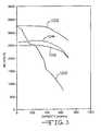
- FIG. 3is a graph constructed from the simultaneous discharge of an electrochemical cell according to the present invention having a medium rate, constant discharge region and a high rate, pulse discharge region.
- pulsemeans a short burst of electric current of a significantly greater amplitude than that of a pre-pulse current immediately prior to the pulse.
- a pulse trainconsists of at least two pulses of electrical current delivered in relatively short succession with or without open current rest between the pulses.
- a typical current pulseis of about 15.0 mA/cm 2 to about 35.0 mA/cm 2 .
- FIGS. 1 and 2show an electrochemical cell 10 with multiplate electrodes constructed according to the present invention having both a medium rate region 12 and a high rate region 14 hermetically sealed within a metallic, prismatic casing 16 .
- the medium rate region 12preferably provides a relatively constant discharge current and, the high rate region 14 preferably provides a current pulse discharge power source. Both electrode regions are activated with the same electrolyte solution.
- the present multiplate electrode cellcomprises two positive terminal leads 18 , 20 and a common negative terminal lead 22 .
- the medium rate region and the high rate regionhave separate and distinct positive terminals and the same negative terminal, i.e., the prismatic casing 16 .
- Two different loadsare applied to this battery.
- a constant resistance load 24is connected to the positive terminal 18 and the negative terminal 20 , i.e., the casing 16
- a constant current pulse “load” 26is connected to the positive terminal 20 and the casing 16 .
- the housing 16is vacuum filled with a nonaqueous electrolyte common to both the medium rate region 12 and the high rate region 14 .
- a device providing both a constant resistance load and a constant current pulse “load”is, for example, an implantable medical device such as a cardiac defibrillator.
- the anode electrode for the medium rate region and the high rate region of an electrochemical cell with multiplate electrodesis selected from Group IA of the Periodic Table of Elements, including lithium, sodium, potassium, calcium, magnesium or their alloys, or any alkali metal or alkali-earth metal capable of functioning as an anode.
- Alloys and intermetallic compoundsinclude, for example, Li—Si, Li—B and Li—Si—B alloys and intermetallic compounds.
- the preferred anodecomprises lithium, and the more preferred anode comprises a lithium alloy, the preferred lithium alloy being lithium-aluminum with the aluminum comprising from between about 0% to about 50%, by weight, of the alloy.
- the anode for the medium rate region 12 and the high rate region 14is a thin metal sheet or foil 28 of the anode metal, pressed or rolled on a metallic anode current collector, i.e., preferably comprising nickel.
- the anodehas an extended tab or lead of the same material as the anode current collector, i.e., preferably nickel, integrally formed therewith, such as by welding.
- the leadis contacted by a weld to the conductive metal casing 16 serving as the negative terminal 20 in a case-negative configuration for both regions 12 , 14 .
- the casing 16is preferably a prismatic housing that may comprise materials such as stainless steel, mild steel, nickel-plated mild steel, titanium or aluminum, but not limited thereto, so long as the metallic material is compatible for use with the other components of the cell.
- the cathode active material for both the medium rate and high rate regionsmay comprise a metal element, a metal oxide, a mixed metal oxide, a metal sulfide or carbonaceous compounds, and combinations thereof.
- Suitable cathode active materialsinclude silver vanadium oxide (SVO), copper vanadium oxide, copper silver vanadium oxide (CSVO), manganese dioxide, titanium disulfide, copper oxide, copper sulfide, iron sulfide, iron disulfide, lithiated cobalt oxide, lithiated nickel oxide, carbon and fluorinated carbon, and mixtures thereof.
- the cathode active materialcomprises a mixed metal oxide formed by a chemical addition reaction, thermal decomposition reaction, hydrothermal synthesis, sol-gel formation, chemical vapor deposition, ultrasonically generated aerosol deposition, or by a thermal spray coating process of various metal sulfides, metal oxides or metal oxide/elemental metal combinations.
- the materials thereby producedcontain metals and oxides of Groups IB, IIB, IIIB, IVB, VB, VIB, VIIB and VIII of the Periodic Table of Elements, which includes the noble metals and/or their oxide compounds.
- the cathode active materialmay be in a dry powder form pressed onto a conductive metal screen.
- Suitable materials for the cathode current collectorinclude aluminum and titanium, preferably titanium.
- the cathode active material in a finely divided formis mixed with conductive diluents and a binder material and then pressed onto the current collector screen.
- the binder materialis preferably a thermoplastic polymeric binder material.
- thermoplastic polymeric binder materialis used in its broad sense and any polymeric material which is inert in the cell and which passes through a thermoplastic state, whether or not it finally sets or cures, is included within the term “thermoplastic polymer”.
- Representative materialsinclude polyethylene, polypropylene and fluoropolymers such as fluorinated ethylene and fluorinated propylene, polyvinylidene fluoride (PVDF) and polytetrafluoroethylene (PTFE), the latter material being most preferred. Natural rubbers are also useful as the binder material with the present invention.
- Suitable discharge promoter diluentsinclude graphite powder, acetylene black powder and carbon black powder.
- Metallic powderssuch as nickel, aluminum, titanium and stainless steel in powder form are also useful as conductive diluents.
- about 80% to about 98%, by weight, of the cathode active materialis mixed with about 1% to about 5% of the conductive diluents and, about 1% to about 5% of the binder material. In some cases, no binder material or electronic conductor material is required to provide a similarly suitable cathode body.
- the cathode structure for the medium rate regionmay also be prepared by rolling, spreading or pressing a mixture of the materials mentioned above onto a suitable current collector.
- the cathode structure for the medium rate region 12is preferably in the form of one or more cathode plates 30 operatively associated with the previously described anode sheet 28 .
- the cathode plates 30have a relatively low surface area and high density.
- this electrode configurationprovides low electrical current on the order of about 1 microampere to about 100 milliamperes corresponding to a C-Rate of about C/2,300,000 to about C/23.
- at least one cathode plate 30 having a thickness of about 0.004 inches to about 0.040 inchesis flanked on either side by oppositely positioned surfaces of the anode 28 prepared as described above.
- the high rate region 14 of the present cellcomprises cathode plates 32 formed from a paste of cathode active material, including binder and conductive additives, calendared into a free-standing structure that is subsequently dried and cut to shape.
- the shaped cathode structure having a thickness of about 0.001 inches to about 0.025 inchesis then pressed onto at least one side and preferably both sides of a current collector screen of a suitable material, such as aluminum or titanium with titanium being preferred, to provide the cathode structure in the form of plates 32 .
- at least one cathode plate 32is flanked on either side by oppositely positioned surfaces of the anode 28 not facing the cathode plates 30 of the medium rate section 12 .
- this electrode configurationprovides electrical current on the order of about 1 amp to about 4 amps corresponding to a C-Rate of about C/2.3 to about C/0.575 for the high rate region.
- a process for making cathode structures useful in the high rate region of the present multiplate electrode cellis described in U.S. Pat. No. 5,435,874 to Takeuchi et al., which is assigned to the assignee of the present invention and incorporated herein by reference.
- An alternate preparation techniqueis to cast a slurry of the cathode active material onto a surface-treated metal foil followed by drying and calendaring.
- the lead 18 for the cathode plates 30 of the medium rate region 12 and the lead 20 for the cathode plates 32 of the high rate region 14are insulated from the casing 16 by respective glass-to-metal seal/terminal lead feedthroughs.
- the glass usedis of a corrosion resistant type having from between about 0% to about 50% by weight silicon such as CABAL 12, TA 23, CORNING 9013, FUSITE 425 or FUSITE 435.
- the positive terminal leads 18 , 20preferably comprise molybdenum although titanium, aluminum, nickel alloy, or stainless steel can also be used.
- the cathode plates 30 , 32 and the anode sheet 28 for both the medium rate and high rate regionsare preferably sealed in their own separator envelopes (not shown for clarity) to prevent direct physical contact between them.
- the separatorsare of an electrically insulative material to prevent an internal electrical short circuit between the active materials, and the separator material also is chemically unreactive with the anode and cathode active materials and both chemically unreactive with and insoluble in the electrolyte.
- the separator materialhas a degree of porosity sufficient to allow flow therethrough of the electrolyte during the electrochemical reaction of the cell.
- Illustrative separator materialsinclude woven and non-woven fabrics of polyolefinic fibers including polypropylene and polyethylene or fluoropolymeric fibers including polyvinylidine fluoride, polyethylenetetrafluoroethylene, and polyethylenechlorotrifluoroethylene laminated or superposed with a polyolefinic or fluoropolymeric microporous film, non-woven glass, glass fiber materials and, ceramic materials.
- Suitable microporous filmsinclude a polytetrafluoroethylene membrane commercially available under the designation ZITEX (Chemplast Inc.), a polypropylene membrane commercially available under the designation CELGARD (Celanese Plastic Company, Inc.) and a membrane commercially available under the designation DEXIGLAS (C. H. Dexter, Div., Dexter Corp.).
- the multiplate electrochemical cell of the present inventionfurther includes a nonaqueous, ionically conductive electrolyte which serves as a medium for migration of ions between the anode and the cathode structures during the electrochemical reactions of the cell.
- the electrochemical reaction at both the medium rate and high rate regionsinvolves conversion of ions in atomic or molecular forms which migrate from the anode to the cathode.
- nonaqueous electrolytes suitable for the present inventionare substantially inert to the anode and cathode materials and, they exhibit those physical properties necessary for ionic transport namely, low viscosity, low surface tension and wettability.
- Suitable electrolytesare comprised of an inorganic salt dissolved in a non-aqueous solvent system.
- the electrolytepreferably comprises an alkali metal salt dissolved in a mixture of aprotic organic solvents comprising a low viscosity solvent including organic esters, ethers, dialkyl carbonates, and mixtures thereof, and a high permittivity solvent including cyclic carbonates, cyclic esters, cyclic amides, and mixtures thereof.
- Low viscosity solventsinclude tetrahydrofuran (THF), diisopropylether, methyl acetate (MA), diglyme, triglyme, tetraglyme, 1,2-dimethoxyethane (DME), 1,2-diethoxyethane (DEE), 1-ethoxy, 2-methoxyethane (EME), dimethyl carbonate (DMC), diethyl carbonate (DEC), dipropyl carbonate (DPC), ethylmethyl carbonate (EMC), methylpropyl carbonate (MPC), ethylpropyl carbonate (EPC), and mixtures thereof.
- THFtetrahydrofuran
- MA1,2-dimethoxyethane
- DEE1,2-diethoxyethane
- EMEdimethyl carbonate
- DECdiethyl carbonate
- DPCdipropyl carbonate
- EMCethylmethyl carbonate
- MPCmethylpropyl carbonate
- High permittivity solventsinclude propylene carbonate (PC), ethylene carbonate (EC), butylene carbonate (BC), acetonitrile, dimethyl sulfoxide, dimethyl formamide, dimethyl acetamide, ⁇ -valerolactone, ⁇ -butyrolactone (GBL), N-methyl-pyrrolidinone (NMP), and mixtures thereof.
- PCpropylene carbonate
- ECethylene carbonate
- BCbutylene carbonate
- acetonitriledimethyl sulfoxide
- dimethyl formamidedimethyl acetamide
- ⁇ -valerolactone⁇ -butyrolactone
- NMPN-methyl-pyrrolidinone
- the preferred electrolyte for both a primary and a secondary cellcomprises a lithium salts selected from the group of LiPF 6 , LiBF 4 , LiAsF 6 , LiSbF 6 , LiClO 4 , LiAlCl 4 , LiGaCl 4 , LiC(SO 2 CF 3 ) 3 , LiN(SO 2 CF 3 ) 2 , LiSCN, LiO 3 SCF 2 CF 3 , LiC 6 F 5 SO 3 , LiO 2 CCF 3 , LiSO 3 F, LiNO 3 , LiB(C 6 H 5 ) 4 , LiCF 3 SO 3 , and mixtures thereof.
- Suitable salt concentrationstypically range between about 0.8 to 1.5 molar.
- the anodeis lithium metal and the preferred electrolyte is 1.0 M to 1.4 M LiAsF 6 dissolved in an aprotic solvent mixture comprising a 50/50 mixture (by volume) of propylene carbonate (PC) and dimethoxyethane (DME).
- PCpropylene carbonate
- DMEdimethoxyethane
- the casing headercomprises a metallic lid (not shown) having a sufficient number of openings to accommodate the glass-to-metal seal/terminal lead feedthroughs for the cathode plates 30 , 32 of the medium and high rate regions 12 , 14 .
- An additional openingis provided for electrolyte filling.
- the casing headercomprises elements having compatibility with the other components of the electrochemical cells and is resistant to corrosion.
- the cellis thereafter filled with the electrolyte solution described hereinabove and hermetically sealed such as by close-welding a stainless steel plug over the fill hole, but not limited thereto.
- An exemplary electrochemical cell dischargeable under both a constant discharge rate and a pulse discharge ratemay be constructed having a capacity (Qa) of the anode and a capacity (Qc) of the high rate region and of the medium rate region as follows:
- a first exemplary conditionconsists of the high rate region and the medium rate region each having a Qa:Qc ratio greater than 0.8:1.0.
- Thisprovides the cell of the present invention with adequate anode capacity (Qa) associated with both the high rate region and the medium rate region dischargeable through both the first and second voltage plateaus expected in the discharge of a conventional Li/SVO cell.
- the Qa:Qc capacity ratio for both the medium rate and high rate regionsmay be as high as 1.1:1.0 or as low as 0.8:1.0 to control cell swelling.
- a second exemplary conditionconsists of the high rate region of the cell of the present invention having a significantly lower Qa:Qc that the medium rate region.
- the Qa:Qc for the high rate regionmay be as low as 0.4:1.0 while the anode capacity to cathode capacity for the medium rate region is about 1.1:1.0.
- the overall cell balancedepends on the ratio of capacity for the high rate region to the medium rate region of the cell.
- the high rate regionis less than 50% less of the total cell capacity, while the medium rate region comprises greater than 50% of the total cell capacity.
- the respective Qa:Qc ratiosare shown in Table 1.
- Li/SVO defibrillator cellsNine lithium/silver vanadium oxide (Li/SVO) defibrillator cells were built.
- the cathode of each cellcomprised a dry mix of SVO combined with a binder material and a conductive diluent pressed into six plates.
- the casing headercontained two terminal pins for connection to the cathode. Specifically, five of six cathode plates were electronically connected to each other and welded to the first terminal pin to provide a high rate discharge region. The remaining cathode plate was welded to the second terminal pin to form a medium rate electrode region.
- the cellswere activated with an electrolyte of LiAsF 6 dissolved in a 50:50 mixture, by volume, of propylene carbonate and dimethoxyethane.
- Two of the experimental cellswere submitted for short circuit testing at 37° C. using a circuit resistance less than or equal to ten milliohms.
- the two cellsexhibited a peak current of 16.7 amps and 17.2 amps, respectively, within one second of application of the short circuit.
- One cellexhibited a peak temperature of 118.0° C. at 9:18 (minutes:seconds) into the test.
- the other cellexhibited a peak temperature of 115.0° C. at 10:30 (minutes:seconds) into the test. Both cells exhibited case swelling. Neither cell was observed to leak, vent or rupture.
- the remaining seven cellswere subjected to burn-in and acceptance pulse testing and then subjected to a modified accelerated discharge data (ADD) test. Based on electrode surface area, the electrical test parameters were modified so that the same current density was applied to the cells during various aspects of the test.
- burn-in and acceptance pulse testingthe two terminal pins were electrically connected and the cells were subjected to a burn-in load of 2.49 kohm for 17 hours.
- the mean pre-load open current volting (OCV) and post-load OCV of the cells during burn-inwas 3.477 volts and 3.200 volts, respectively.
- OCVopen current volting
- the mean pre-pulse OCVwas 3.266 volts.
- the cellswere then subjected to a 2.0 amp acceptance pulse test at 37° C.
- a pulse train sequence of four pulses each of ten seconds duration with fifteen seconds of rest between pulseswas used.
- the mean pre-pulse OCVwas 3.266 volts.
- the average P 1 edge voltage, P 1 minimum voltage, P 1 end voltage, P 4 minimum voltage and post pulse voltage during acceptance pulse testingwas 2.669 volts, 2.404 volts, 2.606 volts, 2.559 volts, and 3.083 volts, respectively.
- the external electrical connection between the two terminal pinswas removed.
- the seven cellswere then submitted for continuous discharge and pulse testing.
- the terminal pin connected to the single cathode plate of the medium rate discharge regionwas connected to a 17.4 kohm resistor. This cathode plate continuously supplied a background current for the cell throughout the test.
- a 1.7 amp pulse train of four pulses of ten seconds duration with fifteen seconds of rest between pulseswas applied to the other terminal pin connected to the five cathode plates of the high rate discharge region. All tests were conducted at 37° C.
- the background voltage of the continuous discharge and pulse discharge tested cellsexhibited the characteristic SVO discharge profile and several voltage plateaus were observed.
- the individual cellsprovided thirty-eight pulse trains through one of the terminal pins as the background voltage through the other terminal pin declined to approximately 750 millivolts.
- the pulse 4 minimum voltage of the cellsremained above 2.0 volts and the pre-pulse OCV of the electrode assembly designated for high rate pulsing remained above 2.70 volts.
- the discharge profile, voltage response and capacity provided by the seven cellswas similar.
- FIG. 3is a graph constructed from the simultaneous continuous discharge and pulse discharge of a representative one of the group of seven cells.
- curve 100was constructed from the background current of the medium rate, constant discharge region of the present invention cell and, curve 102 was constructed from the open circuit voltage of the high rate, pulse discharge region, curve 104 was constructed from the pulse 1 minimum voltage and curve 106 was constructed from the pulse 4 minimum voltage of the pulse discharge region.
Landscapes
- Engineering & Computer Science (AREA)
- Manufacturing & Machinery (AREA)
- Chemical & Material Sciences (AREA)
- Chemical Kinetics & Catalysis (AREA)
- Electrochemistry (AREA)
- General Chemical & Material Sciences (AREA)
- Battery Electrode And Active Subsutance (AREA)
- Secondary Cells (AREA)
Abstract
Description
| TABLE 1 | ||||
| High Rate | Medium Rate | Total Cell | ||
| Region (Qa:Qc) | Region (Qa:Qc) | Capacity (Qa:Qc) | ||
| 0.4:1.0 | 1.1:1.0 | 0.75:1.0 | ||
| TABLE 2 | ||||
| High Rate | Medium Rate | Total Cell | ||
| Region (Qa:Qc) | Region (Qa:Qc) | Capacity (Qa:Qc) | ||
| [0.4:1.0] | [1.1:1.0] | 0.82:1.0 | ||
| 40% of total | 60% of total | |||
| cathode capacity | cathode capacity | |||
Claims (14)
Priority Applications (1)
| Application Number | Priority Date | Filing Date | Title |
|---|---|---|---|
| US09/848,457US6677077B2 (en) | 1997-04-04 | 2001-05-03 | Electrochemical cell having multiplate electrodes with differing discharge rate regions |
Applications Claiming Priority (3)
| Application Number | Priority Date | Filing Date | Title |
|---|---|---|---|
| US08/832,803US5935724A (en) | 1997-04-04 | 1997-04-04 | Electrochemical cell having multiplate electrodes with differing discharge rate regions |
| US09/247,347US6258473B1 (en) | 1997-04-04 | 1999-02-10 | Electrochemical cell having multiplate electrodes with differing discharge rate regions |
| US09/848,457US6677077B2 (en) | 1997-04-04 | 2001-05-03 | Electrochemical cell having multiplate electrodes with differing discharge rate regions |
Related Parent Applications (1)
| Application Number | Title | Priority Date | Filing Date |
|---|---|---|---|
| US09/247,347Continuation-In-PartUS6258473B1 (en) | 1995-09-01 | 1999-02-10 | Electrochemical cell having multiplate electrodes with differing discharge rate regions |
Publications (2)
| Publication Number | Publication Date |
|---|---|
| US20010038943A1 US20010038943A1 (en) | 2001-11-08 |
| US6677077B2true US6677077B2 (en) | 2004-01-13 |
Family
ID=26938613
Family Applications (1)
| Application Number | Title | Priority Date | Filing Date |
|---|---|---|---|
| US09/848,457Expired - LifetimeUS6677077B2 (en) | 1997-04-04 | 2001-05-03 | Electrochemical cell having multiplate electrodes with differing discharge rate regions |
Country Status (1)
| Country | Link |
|---|---|
| US (1) | US6677077B2 (en) |
Cited By (21)
| Publication number | Priority date | Publication date | Assignee | Title |
|---|---|---|---|---|
| US20050084755A1 (en)* | 2003-08-08 | 2005-04-21 | David Boone | High capacity alkaline cells |
| US20050271941A1 (en)* | 2004-06-04 | 2005-12-08 | Bushong William C | Alkaline cells having high capacity |
| US20060257728A1 (en)* | 2003-08-08 | 2006-11-16 | Rovcal, Inc. | Separators for use in alkaline cells having high capacity |
| US20070281213A1 (en)* | 2006-06-02 | 2007-12-06 | Gentcorp Ltd. | Carbon Monofluoride Cathode Materials Providing Simplified Elective Replacement Indication |
| US20080038634A1 (en)* | 2003-12-10 | 2008-02-14 | Rovcal, Inc. | High Capacity Alkaline Cell Utilizing Cathode Extender |
| US20090284229A1 (en)* | 2008-05-19 | 2009-11-19 | Arizona Board Of Regents For And On Behalf Of Arizona State University | Electrochemical cell, and particularly a cell with electrodeposited fuel |
| USRE41886E1 (en) | 2002-06-05 | 2010-10-26 | Eveready Battery Company, Inc. | Nonaqueous electrochemical cell with improved energy density |
| US20110086278A1 (en)* | 2009-10-08 | 2011-04-14 | Fluidic, Inc. | Electrochemical cell with flow management system |
| US8659268B2 (en) | 2010-06-24 | 2014-02-25 | Fluidic, Inc. | Electrochemical cell with stepped scaffold fuel anode |
| US8911910B2 (en) | 2010-11-17 | 2014-12-16 | Fluidic, Inc. | Multi-mode charging of hierarchical anode |
| US20150084604A1 (en)* | 2013-09-26 | 2015-03-26 | Eaglepicher Technologies, Llc | Lithium-sulfur battery and methods of preventing insoluble solid lithium-polysulfide deposition |
| US9105946B2 (en) | 2010-10-20 | 2015-08-11 | Fluidic, Inc. | Battery resetting process for scaffold fuel electrode |
| US9178207B2 (en) | 2010-09-16 | 2015-11-03 | Fluidic, Inc. | Electrochemical cell system with a progressive oxygen evolving electrode / fuel electrode |
| US11251476B2 (en) | 2019-05-10 | 2022-02-15 | Form Energy, Inc. | Nested annular metal-air cell and systems containing same |
| US11664547B2 (en) | 2016-07-22 | 2023-05-30 | Form Energy, Inc. | Moisture and carbon dioxide management system in electrochemical cells |
| US12136723B2 (en) | 2016-07-22 | 2024-11-05 | Form Energy, Inc. | Mist elimination system for electrochemical cells |
| US12237548B2 (en) | 2018-06-29 | 2025-02-25 | Form Energy, Inc. | Stack of electric batteries including series of fluidly connected unit cells |
| US12261281B2 (en) | 2018-06-29 | 2025-03-25 | Form Energy, Inc. | Metal air electrochemical cell architecture |
| US12308414B2 (en) | 2019-06-28 | 2025-05-20 | Form Energy, Inc. | Device architectures for metal-air batteries |
| US12381244B2 (en) | 2020-05-06 | 2025-08-05 | Form Energy, Inc. | Decoupled electrode electrochemical energy storage system |
| US12444755B2 (en) | 2024-02-08 | 2025-10-14 | Form Energy, Inc. | Corrugated fuel electrode |
Families Citing this family (8)
| Publication number | Priority date | Publication date | Assignee | Title |
|---|---|---|---|---|
| JP2006524901A (en) | 2003-04-23 | 2006-11-02 | リチャージャブル バッテリー コーポレイション | Battery using electrode pellet with embedded internal electrode |
| JP4749333B2 (en)* | 2003-09-02 | 2011-08-17 | リチャージャブル バッテリー コーポレイション | Battery cell having improved power characteristics and method of manufacturing the same |
| US7288126B2 (en)* | 2003-09-02 | 2007-10-30 | Rechargeable Battery Corporation | Battery cells having improved power characteristics and methods of manufacturing same |
| US7264903B2 (en)* | 2003-09-02 | 2007-09-04 | Rechargeable Battery Corporation | Battery cells having improved power characteristics and methods of manufacturing same |
| US20070281207A1 (en)* | 2003-12-09 | 2007-12-06 | Takeuchi Esther S | Prevention of lithium deposition in nonaqueous electrolyte cells by matching device usage to cell capacity |
| CA2566658C (en)* | 2004-05-14 | 2011-05-10 | Rechargeable Battery Corporation | Embedded electrode conformations for balanced energy, power, and cost in an alkaline cell |
| US7776470B2 (en)* | 2005-09-28 | 2010-08-17 | Greatbatch Ltd. | Anode-to-cathode capacity ratios for SVO/CF x hybrid cathode electrochemical cells |
| CN112487735B (en)* | 2020-12-02 | 2024-03-15 | 浙大城市学院 | Power balance model method for fluid lithium-oxygen battery |
Citations (26)
| Publication number | Priority date | Publication date | Assignee | Title |
|---|---|---|---|---|
| US1024577A (en) | 1907-07-27 | 1912-04-30 | Charles E Hite | Primary battery. |
| GB254853A (en) | 1925-05-25 | 1926-07-15 | American Bank Note Co | Improvements in or relating to delivery mechanism for printing machines |
| US2905738A (en) | 1955-12-14 | 1959-09-22 | Yardney International Corp | Battery electrode structure |
| US3393097A (en) | 1966-07-29 | 1968-07-16 | Dow Chemical Co | Primary cell having a folded magnesium anode |
| US3861397A (en) | 1972-01-03 | 1975-01-21 | Siemens Ag | Implantable fuel cell |
| US3982966A (en) | 1974-04-01 | 1976-09-28 | Union Carbide Corporation | Alkaline cell with double collector positive, negative and third terminal connections |
| US4031899A (en) | 1976-01-22 | 1977-06-28 | Vitatron Medical B.V. | Long life cardiac pacer with switching power delivery means and method of alternately delivering power to respective circuit portions of a stimulus delivery system |
| US4154906A (en) | 1976-02-18 | 1979-05-15 | Union Carbide Corporation | Cathode or cathode collector arcuate bodies for use in various cell systems |
| US4447504A (en) | 1983-01-03 | 1984-05-08 | Gte Products Corporation | Electrochemical cell with two rate battery stacks |
| US4830940A (en) | 1986-01-14 | 1989-05-16 | Wilson Greatbatch Ltd. | Non-agueous lithium battery |
| US4879190A (en) | 1988-08-30 | 1989-11-07 | Mhb Joint Venture | Electrochemical cell |
| US5164273A (en) | 1991-07-19 | 1992-11-17 | Andras Szasz | Pseudo dual circuit battery and circuit for use |
| US5169732A (en) | 1991-02-04 | 1992-12-08 | Donald T. Beldock | Sealed battery with integral reserve cell and switch |
| US5183712A (en) | 1991-02-04 | 1993-02-02 | Donald T. Beldock | Battery having reserve cell and three or more terminals |
| US5434017A (en)* | 1993-11-19 | 1995-07-18 | Medtronic, Inc. | Isolated connection for an electrochemical cell |
| US5439756A (en) | 1994-02-28 | 1995-08-08 | Motorola, Inc. | Electrical energy storage device and method of charging and discharging same |
| US5447806A (en) | 1993-02-24 | 1995-09-05 | Varta Batterie Aktiengesellschaft | Gas-tight sealed nickel/hydride battery |
| US5458997A (en) | 1994-08-19 | 1995-10-17 | Medtronic, Inc. | Rebalancing of lithium/silver vandium oxide (Li/SVO) cells for improved performance |
| US5534369A (en) | 1994-03-10 | 1996-07-09 | Hival Ltd. | Battery having divided electrode portions |
| US5569553A (en) | 1995-03-08 | 1996-10-29 | Wilson Greatbatch Ltd. | Battery design for achieving end-of-life indication during electrical discharge |
| US5614331A (en) | 1995-12-22 | 1997-03-25 | Wilson Greatbatch Ltd. | Medium and high discharge rate combination battery and method |
| US5624767A (en) | 1995-06-07 | 1997-04-29 | Wilson Greatbatch Ltd. | Alkali metal cell having main and alternate electrodes |
| US5667910A (en) | 1996-04-03 | 1997-09-16 | Wilson Greatbatch Ltd. | Electrochemical cell having a cathode comprising differing active formulations and method |
| US5670266A (en) | 1996-10-28 | 1997-09-23 | Motorola, Inc. | Hybrid energy storage system |
| US6117585A (en) | 1997-07-25 | 2000-09-12 | Motorola, Inc. | Hybrid energy storage device |
| US6165638A (en)* | 1997-04-04 | 2000-12-26 | Wilson Greatbatch Ltd. | Electrochemical cell having multiplate and jellyroll electrodes with differing discharge rate regions |
- 2001
- 2001-05-03USUS09/848,457patent/US6677077B2/ennot_activeExpired - Lifetime
Patent Citations (26)
| Publication number | Priority date | Publication date | Assignee | Title |
|---|---|---|---|---|
| US1024577A (en) | 1907-07-27 | 1912-04-30 | Charles E Hite | Primary battery. |
| GB254853A (en) | 1925-05-25 | 1926-07-15 | American Bank Note Co | Improvements in or relating to delivery mechanism for printing machines |
| US2905738A (en) | 1955-12-14 | 1959-09-22 | Yardney International Corp | Battery electrode structure |
| US3393097A (en) | 1966-07-29 | 1968-07-16 | Dow Chemical Co | Primary cell having a folded magnesium anode |
| US3861397A (en) | 1972-01-03 | 1975-01-21 | Siemens Ag | Implantable fuel cell |
| US3982966A (en) | 1974-04-01 | 1976-09-28 | Union Carbide Corporation | Alkaline cell with double collector positive, negative and third terminal connections |
| US4031899A (en) | 1976-01-22 | 1977-06-28 | Vitatron Medical B.V. | Long life cardiac pacer with switching power delivery means and method of alternately delivering power to respective circuit portions of a stimulus delivery system |
| US4154906A (en) | 1976-02-18 | 1979-05-15 | Union Carbide Corporation | Cathode or cathode collector arcuate bodies for use in various cell systems |
| US4447504A (en) | 1983-01-03 | 1984-05-08 | Gte Products Corporation | Electrochemical cell with two rate battery stacks |
| US4830940A (en) | 1986-01-14 | 1989-05-16 | Wilson Greatbatch Ltd. | Non-agueous lithium battery |
| US4879190A (en) | 1988-08-30 | 1989-11-07 | Mhb Joint Venture | Electrochemical cell |
| US5169732A (en) | 1991-02-04 | 1992-12-08 | Donald T. Beldock | Sealed battery with integral reserve cell and switch |
| US5183712A (en) | 1991-02-04 | 1993-02-02 | Donald T. Beldock | Battery having reserve cell and three or more terminals |
| US5164273A (en) | 1991-07-19 | 1992-11-17 | Andras Szasz | Pseudo dual circuit battery and circuit for use |
| US5447806A (en) | 1993-02-24 | 1995-09-05 | Varta Batterie Aktiengesellschaft | Gas-tight sealed nickel/hydride battery |
| US5434017A (en)* | 1993-11-19 | 1995-07-18 | Medtronic, Inc. | Isolated connection for an electrochemical cell |
| US5439756A (en) | 1994-02-28 | 1995-08-08 | Motorola, Inc. | Electrical energy storage device and method of charging and discharging same |
| US5534369A (en) | 1994-03-10 | 1996-07-09 | Hival Ltd. | Battery having divided electrode portions |
| US5458997A (en) | 1994-08-19 | 1995-10-17 | Medtronic, Inc. | Rebalancing of lithium/silver vandium oxide (Li/SVO) cells for improved performance |
| US5569553A (en) | 1995-03-08 | 1996-10-29 | Wilson Greatbatch Ltd. | Battery design for achieving end-of-life indication during electrical discharge |
| US5624767A (en) | 1995-06-07 | 1997-04-29 | Wilson Greatbatch Ltd. | Alkali metal cell having main and alternate electrodes |
| US5614331A (en) | 1995-12-22 | 1997-03-25 | Wilson Greatbatch Ltd. | Medium and high discharge rate combination battery and method |
| US5667910A (en) | 1996-04-03 | 1997-09-16 | Wilson Greatbatch Ltd. | Electrochemical cell having a cathode comprising differing active formulations and method |
| US5670266A (en) | 1996-10-28 | 1997-09-23 | Motorola, Inc. | Hybrid energy storage system |
| US6165638A (en)* | 1997-04-04 | 2000-12-26 | Wilson Greatbatch Ltd. | Electrochemical cell having multiplate and jellyroll electrodes with differing discharge rate regions |
| US6117585A (en) | 1997-07-25 | 2000-09-12 | Motorola, Inc. | Hybrid energy storage device |
Cited By (30)
| Publication number | Priority date | Publication date | Assignee | Title |
|---|---|---|---|---|
| USRE41886E1 (en) | 2002-06-05 | 2010-10-26 | Eveready Battery Company, Inc. | Nonaqueous electrochemical cell with improved energy density |
| US7931981B2 (en) | 2003-08-08 | 2011-04-26 | Rovcal Inc. | Separators for alkaline electrochemical cells |
| US20060257728A1 (en)* | 2003-08-08 | 2006-11-16 | Rovcal, Inc. | Separators for use in alkaline cells having high capacity |
| US20050084755A1 (en)* | 2003-08-08 | 2005-04-21 | David Boone | High capacity alkaline cells |
| US7645540B2 (en) | 2003-08-08 | 2010-01-12 | Rovcal, Inc. | Separators for alkaline electrochemical cells |
| US7763384B2 (en) | 2003-08-08 | 2010-07-27 | Rovcal, Inc. | Alkaline cells having high capacity |
| US20080038634A1 (en)* | 2003-12-10 | 2008-02-14 | Rovcal, Inc. | High Capacity Alkaline Cell Utilizing Cathode Extender |
| US20050271941A1 (en)* | 2004-06-04 | 2005-12-08 | Bushong William C | Alkaline cells having high capacity |
| US7740984B2 (en) | 2004-06-04 | 2010-06-22 | Rovcal, Inc. | Alkaline cells having high capacity |
| US20070281213A1 (en)* | 2006-06-02 | 2007-12-06 | Gentcorp Ltd. | Carbon Monofluoride Cathode Materials Providing Simplified Elective Replacement Indication |
| US8546028B2 (en) | 2008-05-19 | 2013-10-01 | Arizona Board Of Regents For And On Behalf Of Arizona State University | Electrochemical cell, and particularly a cell with electrodeposited fuel |
| US8309259B2 (en) | 2008-05-19 | 2012-11-13 | Arizona Board Of Regents For And On Behalf Of Arizona State University | Electrochemical cell, and particularly a cell with electrodeposited fuel |
| US20090284229A1 (en)* | 2008-05-19 | 2009-11-19 | Arizona Board Of Regents For And On Behalf Of Arizona State University | Electrochemical cell, and particularly a cell with electrodeposited fuel |
| US20110086278A1 (en)* | 2009-10-08 | 2011-04-14 | Fluidic, Inc. | Electrochemical cell with flow management system |
| US8492052B2 (en) | 2009-10-08 | 2013-07-23 | Fluidic, Inc. | Electrochemical cell with spacers for flow management system |
| US8659268B2 (en) | 2010-06-24 | 2014-02-25 | Fluidic, Inc. | Electrochemical cell with stepped scaffold fuel anode |
| US9178207B2 (en) | 2010-09-16 | 2015-11-03 | Fluidic, Inc. | Electrochemical cell system with a progressive oxygen evolving electrode / fuel electrode |
| US9105946B2 (en) | 2010-10-20 | 2015-08-11 | Fluidic, Inc. | Battery resetting process for scaffold fuel electrode |
| US9214830B2 (en) | 2010-10-20 | 2015-12-15 | Fluidic, Inc. | Battery resetting process for scaffold fuel electrode |
| US8911910B2 (en) | 2010-11-17 | 2014-12-16 | Fluidic, Inc. | Multi-mode charging of hierarchical anode |
| US20150084604A1 (en)* | 2013-09-26 | 2015-03-26 | Eaglepicher Technologies, Llc | Lithium-sulfur battery and methods of preventing insoluble solid lithium-polysulfide deposition |
| US9455447B2 (en)* | 2013-09-26 | 2016-09-27 | Eaglepicher Technologies, Llc | Lithium-sulfur battery and methods of preventing insoluble solid lithium-polysulfide deposition |
| US11664547B2 (en) | 2016-07-22 | 2023-05-30 | Form Energy, Inc. | Moisture and carbon dioxide management system in electrochemical cells |
| US12136723B2 (en) | 2016-07-22 | 2024-11-05 | Form Energy, Inc. | Mist elimination system for electrochemical cells |
| US12237548B2 (en) | 2018-06-29 | 2025-02-25 | Form Energy, Inc. | Stack of electric batteries including series of fluidly connected unit cells |
| US12261281B2 (en) | 2018-06-29 | 2025-03-25 | Form Energy, Inc. | Metal air electrochemical cell architecture |
| US11251476B2 (en) | 2019-05-10 | 2022-02-15 | Form Energy, Inc. | Nested annular metal-air cell and systems containing same |
| US12308414B2 (en) | 2019-06-28 | 2025-05-20 | Form Energy, Inc. | Device architectures for metal-air batteries |
| US12381244B2 (en) | 2020-05-06 | 2025-08-05 | Form Energy, Inc. | Decoupled electrode electrochemical energy storage system |
| US12444755B2 (en) | 2024-02-08 | 2025-10-14 | Form Energy, Inc. | Corrugated fuel electrode |
Also Published As
| Publication number | Publication date |
|---|---|
| US20010038943A1 (en) | 2001-11-08 |
Similar Documents
| Publication | Publication Date | Title |
|---|---|---|
| US6258473B1 (en) | Electrochemical cell having multiplate electrodes with differing discharge rate regions | |
| US6165638A (en) | Electrochemical cell having multiplate and jellyroll electrodes with differing discharge rate regions | |
| US6677077B2 (en) | Electrochemical cell having multiplate electrodes with differing discharge rate regions | |
| US5614331A (en) | Medium and high discharge rate combination battery and method | |
| EP0930664B1 (en) | Control of swelling in alkali metal electrochemical cells | |
| US6627337B2 (en) | Conversion of low rate energy into high rate energy by parallel discharging | |
| US6228534B1 (en) | Annealing of mixed metal oxide electrodes to reduce polarization resistance | |
| US6221534B1 (en) | Alkali metal electrochemical cell having an improved cathode activated with a nonaqueous electrolyte having a carbonate additive | |
| US6551747B1 (en) | Sandwich cathode design for alkali metal electrochemical cell with high discharge rate capability | |
| US6541140B1 (en) | Electrochemical lithium ion secondary cell having multiplate electrodes with differing discharge rate regions | |
| US6641953B2 (en) | Secondary cell with high rate pulse capability | |
| US6692865B2 (en) | Double current collector cathode design using mixtures of two active materials for alkali metal or ion electrochemical cells | |
| US6008625A (en) | Use of double cells to power an implantable medical device | |
| US6623884B1 (en) | Electrochemical lithium ion secondary cell having multiplate and jellyroll electrodes with differing discharge rate regions | |
| US20030104270A1 (en) | Double current collector positive electrode for alkali metal ion electrochemical cells | |
| EP1143544A2 (en) | Application of Gamma-SVO and mixture of Gamma-SVO/ Epsilon-SVO in high rate electrochemical lithium cells containing SVO/CFx/SVO sandwich cathodes | |
| US7108942B1 (en) | Efficient electrode assembly design for cells with alkali metal anodes | |
| US6801016B2 (en) | Matching cells for a battery pack | |
| US20030113613A1 (en) | High energy density rechargeable cell for medical device applications | |
| US7432001B1 (en) | Prevention of lithium deposition in nonaqueous electrolyte cells by electrolyte-to-cathode weight ratio | |
| US7056358B2 (en) | Method for using high rate lithium electrochemical cell containing SVO/CFchi/SVo sandwich cathodes having γ-SVO and mixture of γ-SVO/ε-SVO |
Legal Events
| Date | Code | Title | Description |
|---|---|---|---|
| AS | Assignment | Owner name:WILSON GREATBATCH LTD., NEW YORK Free format text:ASSIGNMENT OF ASSIGNORS INTEREST;ASSIGNORS:SPILLMAN, DAVID M.;TAKEUCHI, ESTHER S.;REEL/FRAME:011777/0059;SIGNING DATES FROM 20010427 TO 20010430 | |
| STCF | Information on status: patent grant | Free format text:PATENTED CASE | |
| AS | Assignment | Owner name:GREATBATCH, LTD. (NEW YORK CORPORATION), NEW YORK Free format text:CHANGE OF NAME;ASSIGNOR:WILSON GREATBATCH,TD.;REEL/FRAME:019520/0743 Effective date:20050524 | |
| FPAY | Fee payment | Year of fee payment:4 | |
| AS | Assignment | Owner name:MANUFACTURERS AND TRADERS TRUST COMPANY, NEW YORK Free format text:SECURITY INTEREST;ASSIGNOR:GREATBATCH LTD.;REEL/FRAME:020571/0205 Effective date:20070522 Owner name:MANUFACTURERS AND TRADERS TRUST COMPANY,NEW YORK Free format text:SECURITY INTEREST;ASSIGNOR:GREATBATCH LTD.;REEL/FRAME:020571/0205 Effective date:20070522 | |
| FEPP | Fee payment procedure | Free format text:PAYOR NUMBER ASSIGNED (ORIGINAL EVENT CODE: ASPN); ENTITY STATUS OF PATENT OWNER: LARGE ENTITY | |
| FPAY | Fee payment | Year of fee payment:8 | |
| FPAY | Fee payment | Year of fee payment:12 | |
| AS | Assignment | Owner name:MANUFACTURERS AND TRADERS TRUST COMPANY, NEW YORK Free format text:SECURITY INTEREST;ASSIGNORS:GREATBATCH, INC.;GREATBATCH LTD.;ELECTROCHEM SOLUTIONS, INC.;AND OTHERS;REEL/FRAME:036980/0482 Effective date:20151027 | |
| AS | Assignment | Owner name:MICRO POWER ELECTRONICS, INC., NEW YORK Free format text:RELEASE BY SECURED PARTY;ASSIGNOR:MANUFACTURERS AND TRADERS TRUST COMPANY (AS ADMINISTRATIVE AGENT);REEL/FRAME:060938/0069 Effective date:20210903 Owner name:PRECIMED INC., NEW YORK Free format text:RELEASE BY SECURED PARTY;ASSIGNOR:MANUFACTURERS AND TRADERS TRUST COMPANY (AS ADMINISTRATIVE AGENT);REEL/FRAME:060938/0069 Effective date:20210903 Owner name:GREATBATCH-GLOBE TOOL, INC., NEW YORK Free format text:RELEASE BY SECURED PARTY;ASSIGNOR:MANUFACTURERS AND TRADERS TRUST COMPANY (AS ADMINISTRATIVE AGENT);REEL/FRAME:060938/0069 Effective date:20210903 Owner name:NEURONEXUS TECHNOLOGIES, INC., NEW YORK Free format text:RELEASE BY SECURED PARTY;ASSIGNOR:MANUFACTURERS AND TRADERS TRUST COMPANY (AS ADMINISTRATIVE AGENT);REEL/FRAME:060938/0069 Effective date:20210903 Owner name:ELECTROCHEM SOLUTIONS, INC., NEW YORK Free format text:RELEASE BY SECURED PARTY;ASSIGNOR:MANUFACTURERS AND TRADERS TRUST COMPANY (AS ADMINISTRATIVE AGENT);REEL/FRAME:060938/0069 Effective date:20210903 Owner name:GREATBATCH LTD., NEW YORK Free format text:RELEASE BY SECURED PARTY;ASSIGNOR:MANUFACTURERS AND TRADERS TRUST COMPANY (AS ADMINISTRATIVE AGENT);REEL/FRAME:060938/0069 Effective date:20210903 Owner name:GREATBATCH, INC., NEW YORK Free format text:RELEASE BY SECURED PARTY;ASSIGNOR:MANUFACTURERS AND TRADERS TRUST COMPANY (AS ADMINISTRATIVE AGENT);REEL/FRAME:060938/0069 Effective date:20210903 Owner name:GREATBATCH LTD., NEW YORK Free format text:RELEASE BY SECURED PARTY;ASSIGNOR:MANUFACTURERS AND TRADERS TRUST COMPANY (AS ADMINISTRATIVE AGENT);REEL/FRAME:058574/0437 Effective date:20210903 | |
| AS | Assignment | Owner name:MICRO POWER ELECTRONICS, INC., NEW YORK Free format text:RELEASE BY SECURED PARTY;ASSIGNOR:MANUFACTURERS AND TRADERS TRUST COMPANY (AS ADMINISTRATIVE AGENT);REEL/FRAME:061659/0858 Effective date:20210903 Owner name:PRECIMED INC., NEW YORK Free format text:RELEASE BY SECURED PARTY;ASSIGNOR:MANUFACTURERS AND TRADERS TRUST COMPANY (AS ADMINISTRATIVE AGENT);REEL/FRAME:061659/0858 Effective date:20210903 Owner name:GREATBATCH-GLOBE TOOL, INC., NEW YORK Free format text:RELEASE BY SECURED PARTY;ASSIGNOR:MANUFACTURERS AND TRADERS TRUST COMPANY (AS ADMINISTRATIVE AGENT);REEL/FRAME:061659/0858 Effective date:20210903 Owner name:NEURONEXUS TECHNOLOGIES, INC., NEW YORK Free format text:RELEASE BY SECURED PARTY;ASSIGNOR:MANUFACTURERS AND TRADERS TRUST COMPANY (AS ADMINISTRATIVE AGENT);REEL/FRAME:061659/0858 Effective date:20210903 Owner name:ELECTROCHEM SOLUTIONS, INC., NEW YORK Free format text:RELEASE BY SECURED PARTY;ASSIGNOR:MANUFACTURERS AND TRADERS TRUST COMPANY (AS ADMINISTRATIVE AGENT);REEL/FRAME:061659/0858 Effective date:20210903 Owner name:GREATBATCH LTD., NEW YORK Free format text:RELEASE BY SECURED PARTY;ASSIGNOR:MANUFACTURERS AND TRADERS TRUST COMPANY (AS ADMINISTRATIVE AGENT);REEL/FRAME:061659/0858 Effective date:20210903 Owner name:GREATBATCH, INC., NEW YORK Free format text:RELEASE BY SECURED PARTY;ASSIGNOR:MANUFACTURERS AND TRADERS TRUST COMPANY (AS ADMINISTRATIVE AGENT);REEL/FRAME:061659/0858 Effective date:20210903 |