US6676826B2 - Method for production of a rotor for centrifugal compressors - Google Patents
Method for production of a rotor for centrifugal compressorsDownload PDFInfo
- Publication number
- US6676826B2 US6676826B2US09/988,981US98898101AUS6676826B2US 6676826 B2US6676826 B2US 6676826B2US 98898101 AUS98898101 AUS 98898101AUS 6676826 B2US6676826 B2US 6676826B2
- Authority
- US
- United States
- Prior art keywords
- electrode
- rotor
- blades
- disk
- cavities
- Prior art date
- Legal status (The legal status is an assumption and is not a legal conclusion. Google has not performed a legal analysis and makes no representation as to the accuracy of the status listed.)
- Expired - Lifetime, expires
Links
- 238000004519manufacturing processMethods0.000titleclaimsabstractdescription16
- 238000000034methodMethods0.000claimsabstractdescription31
- 239000002184metalSubstances0.000claimsdescription10
- 238000009760electrical discharge machiningMethods0.000claimsdescription8
- 239000012530fluidSubstances0.000claimsdescription6
- 238000009763wire-cut EDMMethods0.000claimsdescription3
- 238000007373indentationMethods0.000claimsdescription2
- 238000003466weldingMethods0.000description5
- 238000005516engineering processMethods0.000description4
- 230000003628erosive effectEffects0.000description4
- 239000007789gasSubstances0.000description4
- 229910000831SteelInorganic materials0.000description2
- 239000007788liquidSubstances0.000description2
- 239000000463materialSubstances0.000description2
- 230000035945sensitivityEffects0.000description2
- 125000006850spacer groupChemical group0.000description2
- 239000010959steelSubstances0.000description2
- 239000011248coating agentSubstances0.000description1
- 238000000576coating methodMethods0.000description1
- 238000005520cutting processMethods0.000description1
- 230000000694effectsEffects0.000description1
- 238000010892electric sparkMethods0.000description1
- 238000010438heat treatmentMethods0.000description1
- 238000002347injectionMethods0.000description1
- 239000007924injectionSubstances0.000description1
- 239000000155meltSubstances0.000description1
- 238000003801millingMethods0.000description1
- 238000012544monitoring processMethods0.000description1
- 230000000737periodic effectEffects0.000description1
- 238000003672processing methodMethods0.000description1
- 230000000306recurrent effectEffects0.000description1
- 238000003860storageMethods0.000description1
Images


Classifications
- B—PERFORMING OPERATIONS; TRANSPORTING
- B23—MACHINE TOOLS; METAL-WORKING NOT OTHERWISE PROVIDED FOR
- B23H—WORKING OF METAL BY THE ACTION OF A HIGH CONCENTRATION OF ELECTRIC CURRENT ON A WORKPIECE USING AN ELECTRODE WHICH TAKES THE PLACE OF A TOOL; SUCH WORKING COMBINED WITH OTHER FORMS OF WORKING OF METAL
- B23H9/00—Machining specially adapted for treating particular metal objects or for obtaining special effects or results on metal objects
- B23H9/10—Working turbine blades or nozzles
- B—PERFORMING OPERATIONS; TRANSPORTING
- B23—MACHINE TOOLS; METAL-WORKING NOT OTHERWISE PROVIDED FOR
- B23H—WORKING OF METAL BY THE ACTION OF A HIGH CONCENTRATION OF ELECTRIC CURRENT ON A WORKPIECE USING AN ELECTRODE WHICH TAKES THE PLACE OF A TOOL; SUCH WORKING COMBINED WITH OTHER FORMS OF WORKING OF METAL
- B23H9/00—Machining specially adapted for treating particular metal objects or for obtaining special effects or results on metal objects
- F—MECHANICAL ENGINEERING; LIGHTING; HEATING; WEAPONS; BLASTING
- F04—POSITIVE - DISPLACEMENT MACHINES FOR LIQUIDS; PUMPS FOR LIQUIDS OR ELASTIC FLUIDS
- F04D—NON-POSITIVE-DISPLACEMENT PUMPS
- F04D29/00—Details, component parts, or accessories
- F04D29/18—Rotors
- F04D29/22—Rotors specially for centrifugal pumps
- F04D29/2205—Conventional flow pattern
- F04D29/2222—Construction and assembly
- F—MECHANICAL ENGINEERING; LIGHTING; HEATING; WEAPONS; BLASTING
- F04—POSITIVE - DISPLACEMENT MACHINES FOR LIQUIDS; PUMPS FOR LIQUIDS OR ELASTIC FLUIDS
- F04D—NON-POSITIVE-DISPLACEMENT PUMPS
- F04D29/00—Details, component parts, or accessories
- F04D29/26—Rotors specially for elastic fluids
- F04D29/28—Rotors specially for elastic fluids for centrifugal or helico-centrifugal pumps for radial-flow or helico-centrifugal pumps
- F04D29/284—Rotors specially for elastic fluids for centrifugal or helico-centrifugal pumps for radial-flow or helico-centrifugal pumps for compressors
- B—PERFORMING OPERATIONS; TRANSPORTING
- B23—MACHINE TOOLS; METAL-WORKING NOT OTHERWISE PROVIDED FOR
- B23H—WORKING OF METAL BY THE ACTION OF A HIGH CONCENTRATION OF ELECTRIC CURRENT ON A WORKPIECE USING AN ELECTRODE WHICH TAKES THE PLACE OF A TOOL; SUCH WORKING COMBINED WITH OTHER FORMS OF WORKING OF METAL
- B23H1/00—Electrical discharge machining, i.e. removing metal with a series of rapidly recurring electrical discharges between an electrode and a workpiece in the presence of a fluid dielectric
- Y—GENERAL TAGGING OF NEW TECHNOLOGICAL DEVELOPMENTS; GENERAL TAGGING OF CROSS-SECTIONAL TECHNOLOGIES SPANNING OVER SEVERAL SECTIONS OF THE IPC; TECHNICAL SUBJECTS COVERED BY FORMER USPC CROSS-REFERENCE ART COLLECTIONS [XRACs] AND DIGESTS
- Y10—TECHNICAL SUBJECTS COVERED BY FORMER USPC
- Y10T—TECHNICAL SUBJECTS COVERED BY FORMER US CLASSIFICATION
- Y10T29/00—Metal working
- Y10T29/49—Method of mechanical manufacture
- Y10T29/49229—Prime mover or fluid pump making
- Y10T29/49236—Fluid pump or compressor making
- Y10T29/49243—Centrifugal type
Definitions
- the present inventionrelates to a method for production of a rotor for centrifugal compressors.
- centrifugal compressornormally defines a machine which restores a compressible fluid, at a pressure which is greater than that at which it received the fluid, imparting to the latter the energy necessary for the change of pressure by means of use of one or a plurality of rotors or impellers, each of which consists of a certain number of blades, which are disposed radially such as to form a certain number of passages which converge towards the centre of the rotor.
- centrifugal compressorsare normally equipped with rotors 20 which are tested in a standard manner.
- the main parts of these rotors for centrifugal compressorsare the hub, the shroud and the blades.
- the entire dynamic behaviour of the rotoris particularly critical for this type of application, and the simplest means for increasing the rigidity of the rotor in the same operative conditions (same bearings, same temperature, same pressure of the gas, etc) is that of using shafts which have large diameters.
- the diameters both of the shafts and of the hubshave thus been increased in the known art, such as to increase the lack of sensitivity to external disturbances, and therefore to improve the characteristic rotodynamic behaviour of high-pressure centrifugal compressors.
- two ringsthe front one of which is in two pieces, and the rear one which is in a single piece, maintain the axial position, whereas a coating with a high level of hardness protects the shaft.
- the bladesare conventionally obtained by means of milling the hub (or shroud), and subsequently the welding is carried out from the interior of the aperture, in order to join the parts.
- Another techniqueis used for rotors with a low flow coefficient, in which the blades are too thin to make it possible to carry out the welding from the interior.
- the two partsare slot-welded from the rear of the hub (the blades are machined on the shroud), owing to the presence of the nose or front portion of the shroud, which has the same diameter as the main end of the blade.
- the heat treatmentis also carried out, which, as will be appreciated, reduces the residual tensions which have formed.
- Each rotoris separated from the others by a spacer, in order to create the necessary aerodynamic space at the intake of the rotor.
- the object of the present inventionis thus to provide a method for production of a rotor for centrifugal compressors, such that the above-described requirements are fulfilled.
- Another object of the present inventionis to provide a method for production of a rotor for centrifugal compressors, which makes it possible to obtain a very high level of dimensional accuracy, which is in line with the required expectations.
- Another object of the present inventionis to provide a method for production of a rotor for centrifugal compressors, which provides the possibility of obtaining a high level of structural resistance of the rotor.
- a further object of the present inventionis to provide a method for production of a rotor for centrifugal compressors, which makes it possible to obtain a high level of dimensional accuracy, as well as an optimum surface quality of the finished product.
- a method for production of a rotor for centrifugal compressorswherein the said rotor is produced from a monolithic disc, provided with a central hole, characterised in that it consists of use, within an isolating medium, of at least one first electrode which has polarity opposite that of the polarity of the said rotor, wherein the said first electrode operates starting from the outer diameter of the said monolithic disc, in order to produce the blades and the cavities of the said rotor, and wherein this processing takes place with a continuous path consisting of a first step of roughing, followed by a second step of finishing with a tool which has a shape similar to that of the electrode used for the first roughing step, in order to produce an accurate geometry of the said blades.
- the method according to the inventionincludes a further step of finishing, in which an electrode operates on the surfaces of the blades, at the inner portion of the said rotor, in order to round the main ends of the said blades, on the inner side of the disc.
- an electrode 15carries out at least the first step of roughing wherein the said electrode is shaped such as to be able to produce the profile of each of the blades, both on the pressure side and on the suction side.
- this electrodehas a first and a second portion, which are separated from one another by the space which is necessary for the presence of a blade.
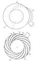
- FIG. 1represents an electrode for electroerosion, which acts on a rotor which is destined for a centrifugal compressor, according to the method of the invention, in a first operative position of erosion;
- FIG. 2represents the electrode for electroerosion in FIG. 1, which acts on the rotor of the compressor, in a second operative position;
- FIG. 3represents a second electrode for electroerosion, which acts on the rotor in FIG. 1, in another operative position;
- FIG. 4represents a third electrode for electroerosion, which acts on the inner part of the rotor in FIG. 1, in yet another operative position;
- FIG. 5represents a fourth electrode for electroerosion, which acts on the inner part of the rotor in FIG. 1, in yet another operative position.
- EDMdie-sinking EDM
- wire-cut EDMElectrical Discharge Machining
- the EDM processusually takes place in an isolating liquid, which is continually regenerated and filtered, such as to remove all the metal residues.
- EDMOwing to these special properties, EDM is considered as a technology with great future prospects.
- the shape requiredis formed negatively in the metal, with a three-dimensional electrode.
- the shape requiredis stored in the computer, and is conveyed in the form of codes which can be understood by the machine, which subsequently cuts the shape independently, guiding the wire along the path.
- the upper and lower wire guiding systemsperform the different movements depending on the cases.
- the starting pointis a monolithic disc 10 , made of steel which is perforated centrally by the hole 11 , in order to produce the radial compressor rotors by means of electroerosion.
- numerically controlled machinesare preferably used.
- the tools for the method and the rotor itselfare electrodes with opposite polarity, and the isolating means are normally oil or specific fluid with a high level of resistivity.
- a first electrodeis able to produce the blades 14 and the cavities 13 of the rotor, starting from the outer diameter of the disc 10 .
- the first electrode 12has the same shape as the aperture itself of the cavity 13 , and moves as illustrated in FIGS. 1-2, in which the initial position and the final position can be seen.
- the electrode 12Since it is a planar object, the electrode 12 must also move in an axial direction.
- the processing with a continuous pathbegins with general erosion, which is followed by a step of finishing with a specific tool, the shape of which is similar to the electrode 12 , but which makes it possible to produce accurate geometry of the blades 14 .
- the blades 14 on the inner side of the disc 10have a flat main end.
- an electrode 15which has the particular shape represented in FIG. 3 can carry out the roughing step of the electroerosion method.
- this electrode 15produces the profile of the blade 14 , both on the pressure side and on the suction side.
- the electrode 15has a first and a second portion 15 ′, 15 ′′, which are separated from one another by the space necessary for the presence of a blade 14 .
- Another important advantageis provided by the possibility of obtaining a high level of structural resistance, as well as of obtaining a high level of dimensional accuracy, and finally an optimum surface quality of the finished product.
- the method according to the inventionmakes it possible to avoid any metallurgical discontinuity inside the rotor, a fact which clearly represents a significant technological step forward.
- centrifugal compressors in questionare normally characterised by a very low flow coefficient.
- the distortion which is associated with the processing known as slot weldingcan modify the width of the blade by 5% or more, for these rotors which have a low flow level.
- the accuracy which can be obtainedis 1-2%, a fact which permits a more accurate match between the performance levels expected and those obtained.
Landscapes
- Engineering & Computer Science (AREA)
- Mechanical Engineering (AREA)
- General Engineering & Computer Science (AREA)
- Physics & Mathematics (AREA)
- Thermal Sciences (AREA)
- Structures Of Non-Positive Displacement Pumps (AREA)
Abstract
Description
Claims (10)
Applications Claiming Priority (3)
| Application Number | Priority Date | Filing Date | Title |
|---|---|---|---|
| ITMI2000A002595 | 2000-11-30 | ||
| IT2000MI002595AIT1319495B1 (en) | 2000-11-30 | 2000-11-30 | PROCEDURE FOR THE CONSTRUCTION OF A ROTOR FOR COMPRESSOR-CENTRIFUGHI. |
| ITMI2000A2595 | 2000-11-30 |
Publications (2)
| Publication Number | Publication Date |
|---|---|
| US20020062561A1 US20020062561A1 (en) | 2002-05-30 |
| US6676826B2true US6676826B2 (en) | 2004-01-13 |
Family
ID=11446154
Family Applications (1)
| Application Number | Title | Priority Date | Filing Date |
|---|---|---|---|
| US09/988,981Expired - LifetimeUS6676826B2 (en) | 2000-11-30 | 2001-11-21 | Method for production of a rotor for centrifugal compressors |
Country Status (7)
| Country | Link |
|---|---|
| US (1) | US6676826B2 (en) |
| EP (1) | EP1211009B1 (en) |
| JP (1) | JP2002235694A (en) |
| AU (1) | AU9145401A (en) |
| DE (1) | DE60142880D1 (en) |
| IT (1) | IT1319495B1 (en) |
| NO (1) | NO330344B1 (en) |
Cited By (4)
| Publication number | Priority date | Publication date | Assignee | Title |
|---|---|---|---|---|
| US20040112871A1 (en)* | 2001-03-14 | 2004-06-17 | Volvo Aero Corporation | Method and a device for manufacturing a stator component or rotor component |
| CN101368573B (en)* | 2008-09-08 | 2010-06-02 | 奇瑞汽车股份有限公司 | Water pump impeller |
| US20110108526A1 (en)* | 2008-10-06 | 2011-05-12 | Hisanori Kishimoto | Method of manufacturing impeller for centrifugal rotating machine |
| US11103945B2 (en) | 2016-07-22 | 2021-08-31 | Hoden Seimitsu Kako Kenkyusho Co., Ltd. | Integrated impeller manufacturing method |
Families Citing this family (20)
| Publication number | Priority date | Publication date | Assignee | Title |
|---|---|---|---|---|
| ITMI20021876A1 (en)* | 2002-09-03 | 2004-03-04 | Nuovo Pignone Spa | IMPROVED PROCEDURE FOR MAKING A ROTOR OF ONE |
| GB0304321D0 (en) | 2003-02-26 | 2003-04-02 | Bladon Jets Ltd | Fans and turbines |
| GB0420022D0 (en) | 2004-09-09 | 2004-10-13 | Bladon Jets Ltd | Fans and turbines |
| US8313300B2 (en) | 2007-06-14 | 2012-11-20 | Christianson Systems, Inc. | Rotor for centrifugal compressor |
| EP2177298A1 (en)* | 2008-10-20 | 2010-04-21 | Sulzer Markets and Technology AG | Manufacturing procedure for closed discs |
| JP5107306B2 (en)* | 2009-06-10 | 2012-12-26 | 三菱重工業株式会社 | Manufacturing method of impeller of centrifugal rotating machine and impeller of centrifugal rotating machine |
| IT1396512B1 (en)* | 2009-10-21 | 2012-12-14 | Nuovo Pignone Spa | METHOD AND DEVICE FOR TOOL COMPENSATION |
| US8387504B2 (en)* | 2011-01-06 | 2013-03-05 | General Electric Company | Fiber-reinforced Al-Li compressor airfoil and method of fabricating |
| JP5606358B2 (en) | 2011-02-24 | 2014-10-15 | 三菱重工業株式会社 | Impeller, rotor provided with the same, and method for manufacturing impeller |
| JP2013047479A (en) | 2011-08-29 | 2013-03-07 | Mitsubishi Heavy Ind Ltd | Impeller and rotary machine with the same, and method for manufacturing impeller |
| JP5907723B2 (en) | 2011-12-26 | 2016-04-26 | 三菱重工業株式会社 | Manufacturing method of rotating machine |
| RU2488026C1 (en)* | 2012-02-21 | 2013-07-20 | Закрытое Акционерное Общество "Русский Вентилятор" (Зао "Рувен") | Radial blower impeller vane |
| RU2522700C1 (en)* | 2013-03-21 | 2014-07-20 | Открытое акционерное общество Научно-производственное объдинение "Искра" | Rotor of centrifugal compressor |
| CN103212760B (en)* | 2013-04-08 | 2016-01-13 | 南京航空航天大学 | A kind of runner processing method between uiform section blade profile integral impeller with ring leaf |
| RU2525037C1 (en)* | 2013-04-19 | 2014-08-10 | ФГБОУ ВПО "Уральский государственный горный университет" | Centrifugal fan impeller |
| ITUA20162126A1 (en)* | 2016-03-30 | 2017-09-30 | Exergy Spa | Method for the construction of bladed discs for radial turbomachinery and bladed disc obtained by this method |
| IT201900015773A1 (en)* | 2019-09-06 | 2021-03-06 | Nuovo Pignone Tecnologie Srl | Process and electric discharge apparatus for processing elongated pieces. |
| CN110732841B (en)* | 2019-10-21 | 2021-05-14 | 山西汾西重工有限责任公司 | Cylindrical thin-wall casting shell split cutting method capable of avoiding stress concentration release |
| CN111687505B (en)* | 2020-05-19 | 2021-06-15 | 南京航空航天大学 | Double-blade nesting electrolytic machining device and its processing method |
| CN114932281B (en)* | 2022-06-07 | 2023-07-28 | 江苏集萃精密制造研究院有限公司 | Front and rear edge cathode three-element design method for precise electrolysis of aero-engine blade |
Citations (3)
| Publication number | Priority date | Publication date | Assignee | Title |
|---|---|---|---|---|
| US4502837A (en) | 1982-09-30 | 1985-03-05 | General Electric Company | Multi stage centrifugal impeller |
| US4653976A (en) | 1982-09-30 | 1987-03-31 | General Electric Company | Method of compressing a fluid flow in a multi stage centrifugal impeller |
| US4851090A (en)* | 1987-05-13 | 1989-07-25 | General Electric Company | Method and apparatus for electrochemically machining airfoil blades |
Family Cites Families (11)
| Publication number | Priority date | Publication date | Assignee | Title |
|---|---|---|---|---|
| US1774279A (en)* | 1926-08-23 | 1930-08-26 | Emil R Lochman | Electric tracer-control machine for die sinking and the like |
| US3372099A (en)* | 1963-05-01 | 1968-03-05 | John E. Clifford | Electrochemical machining using a multisegmented electrode with individual current control for each segment |
| US3288699A (en) | 1964-02-12 | 1966-11-29 | Ex Cell O Corp | Apparatus for electrochemical shaping |
| DE6907998U (en)* | 1969-02-28 | 1969-07-17 | Siemens Ag | TURBO MACHINE, IN PARTICULAR GAS TURBINE OF THE AXIAL DESIGN |
| NL7203180A (en)* | 1972-03-10 | 1973-09-12 | ||
| FR2570970B1 (en)* | 1984-09-28 | 1994-06-03 | Meon Fils Ets | MACHINING PROCESS APPLIED IN PARTICULAR TO TURBINE WHEEL AUGETS, THE MEANS AND MACHINE FOR IMPLEMENTING THIS PROCESS. |
| EP0295206A1 (en)* | 1987-06-10 | 1988-12-14 | Charmilles Technologies S.A. | Device for mounting tool in different directions |
| JPH0796166B2 (en) | 1988-03-01 | 1995-10-18 | エーピーシーエアロスペシャルティ株式会社 | Electrolytic machining method and electrolytic machining apparatus for integrated impeller |
| JPH01271126A (en) | 1988-04-20 | 1989-10-30 | Mitsubishi Electric Corp | Electric discharge machining method |
| IT1238201B (en)* | 1989-11-03 | 1993-07-09 | Varian Spa | METHOD OF MANUFACTURE BY ELECTROEROSION OF A IMPELLER OR A ROTOR TO ONE OR MORE IMPELLERS OF A TURBO PUMP, PARTICULARLY OF A TURBOMOLECULAR PUMP, AND PRODUCTS SO OBTAINED. |
| JP2939310B2 (en)* | 1990-08-14 | 1999-08-25 | 株式会社ソディック | Electric discharge machine |
- 2000
- 2000-11-30ITIT2000MI002595Apatent/IT1319495B1/enactive
- 2001
- 2001-11-21USUS09/988,981patent/US6676826B2/ennot_activeExpired - Lifetime
- 2001-11-22AUAU91454/01Apatent/AU9145401A/ennot_activeAbandoned
- 2001-11-29JPJP2001363609Apatent/JP2002235694A/enactivePending
- 2001-11-29NONO20015822Apatent/NO330344B1/ennot_activeIP Right Cessation
- 2001-11-30DEDE60142880Tpatent/DE60142880D1/ennot_activeExpired - Lifetime
- 2001-11-30EPEP01310033Apatent/EP1211009B1/ennot_activeExpired - Lifetime
Patent Citations (3)
| Publication number | Priority date | Publication date | Assignee | Title |
|---|---|---|---|---|
| US4502837A (en) | 1982-09-30 | 1985-03-05 | General Electric Company | Multi stage centrifugal impeller |
| US4653976A (en) | 1982-09-30 | 1987-03-31 | General Electric Company | Method of compressing a fluid flow in a multi stage centrifugal impeller |
| US4851090A (en)* | 1987-05-13 | 1989-07-25 | General Electric Company | Method and apparatus for electrochemically machining airfoil blades |
Cited By (7)
| Publication number | Priority date | Publication date | Assignee | Title |
|---|---|---|---|---|
| US20040112871A1 (en)* | 2001-03-14 | 2004-06-17 | Volvo Aero Corporation | Method and a device for manufacturing a stator component or rotor component |
| US6797912B2 (en)* | 2001-03-14 | 2004-09-28 | Volvo Aero Corporation | Method and a device for manufacturing a stator component or rotor component |
| CN101368573B (en)* | 2008-09-08 | 2010-06-02 | 奇瑞汽车股份有限公司 | Water pump impeller |
| US20110108526A1 (en)* | 2008-10-06 | 2011-05-12 | Hisanori Kishimoto | Method of manufacturing impeller for centrifugal rotating machine |
| US8581136B2 (en)* | 2008-10-06 | 2013-11-12 | Mitsubishi Heavy Industries, Ltd. | Method of manufacturing by electric discharge machining an impeller for centrifugal rotating machine |
| EP2305411A4 (en)* | 2008-10-06 | 2017-12-27 | Mitsubishi Heavy Industries Compressor Corporation | Method of manufacturing impeller for centrifugal rotary machine |
| US11103945B2 (en) | 2016-07-22 | 2021-08-31 | Hoden Seimitsu Kako Kenkyusho Co., Ltd. | Integrated impeller manufacturing method |
Also Published As
| Publication number | Publication date |
|---|---|
| EP1211009A1 (en) | 2002-06-05 |
| AU9145401A (en) | 2002-06-06 |
| NO20015822D0 (en) | 2001-11-29 |
| US20020062561A1 (en) | 2002-05-30 |
| EP1211009B1 (en) | 2010-08-25 |
| NO20015822L (en) | 2002-05-31 |
| JP2002235694A (en) | 2002-08-23 |
| ITMI20002595A1 (en) | 2002-05-30 |
| IT1319495B1 (en) | 2003-10-20 |
| DE60142880D1 (en) | 2010-10-07 |
| NO330344B1 (en) | 2011-03-28 |
Similar Documents
| Publication | Publication Date | Title |
|---|---|---|
| US6676826B2 (en) | Method for production of a rotor for centrifugal compressors | |
| JP5437559B2 (en) | Method for machining turbine engine components | |
| US7462273B2 (en) | Method and apparatus for forming by electrochemical material removal | |
| EP3486018B1 (en) | Method and device for machining shapes using electrical machining | |
| US8161641B2 (en) | Compound electromachining | |
| JP2015206368A (en) | Improved method of manufacturing a rotor of a centrifugal compressor | |
| JP5112867B2 (en) | Fan and turbine | |
| WO2010041431A1 (en) | Method of manufacturing impeller for centrifugal rotary machine | |
| EP2602039A1 (en) | A method of forming a slot in an article | |
| US9970309B2 (en) | Method for producing a rotor of a charging apparatus | |
| CA2366325A1 (en) | Method of forming turbine blade root | |
| JP5097877B2 (en) | Fan and turbine | |
| WO2014184368A1 (en) | Impeller with backswept circular pipes | |
| EP2483028B1 (en) | Rotary structures | |
| EP2255912B1 (en) | Electric Discharge Machining Device Using Rotating Circular Blade | |
| CN110248755B (en) | Electro-machining system and method | |
| EP2022587B1 (en) | Compound electromachining of turbine blades | |
| US4850147A (en) | Electrode shaping | |
| WO2019092679A1 (en) | Method for the construction of stator and rotor elements of turbomachines | |
| US11235403B2 (en) | Electrical discharge machining electrodes and associated methods | |
| CN110883342B (en) | Processing method of single-stage blade of air-cooled steam turbine generator | |
| EP3612721B1 (en) | Method for the construction of bladed rings for radial turbomachinery | |
| JP5301125B2 (en) | Combined electromachining method | |
| JPH0641053B2 (en) | Method for manufacturing turbine blade | |
| GB2592618A (en) | Turbine blades and methods of manufacture of turbine blades |
Legal Events
| Date | Code | Title | Description |
|---|---|---|---|
| AS | Assignment | Owner name:NUOVO PIGNONE HOLDING S.P.A., ITALY Free format text:ASSIGNMENT OF ASSIGNORS INTEREST;ASSIGNORS:BATTISTINI, VERTER;MARIOTTI, UMBERTO;REEL/FRAME:012317/0319 Effective date:20011109 | |
| FEPP | Fee payment procedure | Free format text:PAYOR NUMBER ASSIGNED (ORIGINAL EVENT CODE: ASPN); ENTITY STATUS OF PATENT OWNER: LARGE ENTITY | |
| STCF | Information on status: patent grant | Free format text:PATENTED CASE | |
| CC | Certificate of correction | ||
| FPAY | Fee payment | Year of fee payment:4 | |
| FPAY | Fee payment | Year of fee payment:8 | |
| FPAY | Fee payment | Year of fee payment:12 | |
| AS | Assignment | Owner name:NUOVO PIGNONE INTERNATIONAL S.R.L., ITALY Free format text:NUNC PRO TUNC ASSIGNMENT;ASSIGNOR:NUOVO PIGNONE HOLDING S.P.A.;REEL/FRAME:059989/0991 Effective date:20220310 | |
| AS | Assignment | Owner name:NUOVO PIGNONE S.R.L., ITALY Free format text:NUNC PRO TUNC ASSIGNMENT;ASSIGNOR:NUOVO PIGNONE INTERNATIONAL S.R.L.;REEL/FRAME:060441/0662 Effective date:20220310 | |
| AS | Assignment | Owner name:NUOVO PIGNONE TECNOLOGIE S.R.L., ITALY Free format text:NUNC PRO TUNC ASSIGNMENT;ASSIGNOR:NUOVO PIGNONE S.R.L.;REEL/FRAME:060243/0913 Effective date:20220530 |