US6676665B2 - Surgical instrumentation and method for treatment of the spine - Google Patents
Surgical instrumentation and method for treatment of the spineDownload PDFInfo
- Publication number
- US6676665B2 US6676665B2US09/928,949US92894901AUS6676665B2US 6676665 B2US6676665 B2US 6676665B2US 92894901 AUS92894901 AUS 92894901AUS 6676665 B2US6676665 B2US 6676665B2
- Authority
- US
- United States
- Prior art keywords
- distal end
- end portion
- instrumentation
- configuration
- displacement
- Prior art date
- Legal status (The legal status is an assumption and is not a legal conclusion. Google has not performed a legal analysis and makes no representation as to the accuracy of the status listed.)
- Expired - Lifetime, expires
Links
- 238000000034methodMethods0.000titleclaimsdescription29
- 238000006073displacement reactionMethods0.000claimsabstractdescription70
- 230000007246mechanismEffects0.000claimsabstractdescription23
- 210000000988bone and boneAnatomy0.000claimsabstractdescription18
- 239000013013elastic materialSubstances0.000claimsabstractdescription9
- 206010010214Compression fractureDiseases0.000claimsabstractdescription7
- 239000000463materialSubstances0.000claimsdescription54
- 238000003780insertionMethods0.000claimsdescription27
- 230000037431insertionEffects0.000claimsdescription27
- 230000004044responseEffects0.000claimsdescription10
- 239000012781shape memory materialSubstances0.000claimsdescription9
- 230000009467reductionEffects0.000claimsdescription5
- 210000001519tissueAnatomy0.000claimsdescription5
- 238000005056compactionMethods0.000claimsdescription4
- 238000012800visualizationMethods0.000claimsdescription4
- 230000007704transitionEffects0.000claimsdescription2
- 239000011521glassSubstances0.000claims1
- 230000000694effectsEffects0.000abstractdescription2
- 229920000147Styrene maleic anhydridePolymers0.000description22
- RTAQQCXQSZGOHL-UHFFFAOYSA-NTitaniumChemical compound[Ti]RTAQQCXQSZGOHL-UHFFFAOYSA-N0.000description9
- 230000006835compressionEffects0.000description9
- 238000007906compressionMethods0.000description9
- 239000010936titaniumSubstances0.000description9
- 229920001971elastomerPolymers0.000description7
- -1for exampleSubstances0.000description7
- 229910000734martensiteInorganic materials0.000description7
- 239000012528membraneSubstances0.000description7
- 239000010935stainless steelSubstances0.000description7
- 229910001220stainless steelInorganic materials0.000description7
- 230000009466transformationEffects0.000description7
- 238000003466weldingMethods0.000description7
- 230000008901benefitEffects0.000description6
- 230000001054cortical effectEffects0.000description5
- 239000007943implantSubstances0.000description5
- 229910052719titaniumInorganic materials0.000description5
- 230000015572biosynthetic processEffects0.000description4
- 229910001000nickel titaniumInorganic materials0.000description4
- 229920000642polymerPolymers0.000description4
- 208000010392Bone FracturesDiseases0.000description3
- 229910001200FerrotitaniumInorganic materials0.000description3
- 238000013459approachMethods0.000description3
- 229910001566austeniteInorganic materials0.000description3
- 239000002131composite materialSubstances0.000description3
- 239000000806elastomerSubstances0.000description3
- HLXZNVUGXRDIFK-UHFFFAOYSA-Nnickel titaniumChemical compound[Ti].[Ti].[Ti].[Ti].[Ti].[Ti].[Ti].[Ti].[Ti].[Ti].[Ti].[Ni].[Ni].[Ni].[Ni].[Ni].[Ni].[Ni].[Ni].[Ni].[Ni].[Ni].[Ni].[Ni].[Ni]HLXZNVUGXRDIFK-UHFFFAOYSA-N0.000description3
- 238000002407reformingMethods0.000description3
- 229910001285shape-memory alloyInorganic materials0.000description3
- 241001465754MetazoaSpecies0.000description2
- VVQNEPGJFQJSBK-UHFFFAOYSA-NMethyl methacrylateChemical compoundCOC(=O)C(C)=CVVQNEPGJFQJSBK-UHFFFAOYSA-N0.000description2
- PXHVJJICTQNCMI-UHFFFAOYSA-NNickelChemical compound[Ni]PXHVJJICTQNCMI-UHFFFAOYSA-N0.000description2
- 229910045601alloyInorganic materials0.000description2
- 239000000956alloySubstances0.000description2
- 239000004568cementSubstances0.000description2
- 238000004891communicationMethods0.000description2
- 238000002788crimpingMethods0.000description2
- 238000012986modificationMethods0.000description2
- 230000004048modificationEffects0.000description2
- 230000001009osteoporotic effectEffects0.000description2
- 230000002441reversible effectEffects0.000description2
- 206010017076FractureDiseases0.000description1
- 229910000990Ni alloyInorganic materials0.000description1
- 229910001069Ti alloyInorganic materials0.000description1
- QCWXUUIWCKQGHC-UHFFFAOYSA-NZirconiumChemical compound[Zr]QCWXUUIWCKQGHC-UHFFFAOYSA-N0.000description1
- 230000004075alterationEffects0.000description1
- 238000005452bendingMethods0.000description1
- 230000036760body temperatureEffects0.000description1
- 239000002639bone cementSubstances0.000description1
- 210000001185bone marrowAnatomy0.000description1
- 239000000316bone substituteSubstances0.000description1
- 230000008859changeEffects0.000description1
- 230000007797corrosionEffects0.000description1
- 238000005260corrosionMethods0.000description1
- 238000005553drillingMethods0.000description1
- 230000005489elastic deformationEffects0.000description1
- 230000035876healingEffects0.000description1
- 238000005286illuminationMethods0.000description1
- KHYBPSFKEHXSLX-UHFFFAOYSA-NiminotitaniumChemical compound[Ti]=NKHYBPSFKEHXSLX-UHFFFAOYSA-N0.000description1
- 230000000977initiatory effectEffects0.000description1
- 230000001788irregularEffects0.000description1
- 230000002262irrigationEffects0.000description1
- 238000003973irrigationMethods0.000description1
- 229920000126latexPolymers0.000description1
- 239000004816latexSubstances0.000description1
- 230000003446memory effectEffects0.000description1
- 229910052759nickelInorganic materials0.000description1
- 229920001296polysiloxanePolymers0.000description1
- 230000001737promoting effectEffects0.000description1
- 239000012858resilient materialSubstances0.000description1
- 230000007480spreadingEffects0.000description1
- 239000000126substanceSubstances0.000description1
- 230000001225therapeutic effectEffects0.000description1
- 229910052726zirconiumInorganic materials0.000description1
Images


Classifications
- A—HUMAN NECESSITIES
- A61—MEDICAL OR VETERINARY SCIENCE; HYGIENE
- A61B—DIAGNOSIS; SURGERY; IDENTIFICATION
- A61B17/00—Surgical instruments, devices or methods
- A61B17/02—Surgical instruments, devices or methods for holding wounds open, e.g. retractors; Tractors
- A61B17/025—Joint distractors
- A—HUMAN NECESSITIES
- A61—MEDICAL OR VETERINARY SCIENCE; HYGIENE
- A61B—DIAGNOSIS; SURGERY; IDENTIFICATION
- A61B17/00—Surgical instruments, devices or methods
- A61B17/56—Surgical instruments or methods for treatment of bones or joints; Devices specially adapted therefor
- A61B17/58—Surgical instruments or methods for treatment of bones or joints; Devices specially adapted therefor for osteosynthesis, e.g. bone plates, screws or setting implements
- A61B17/88—Osteosynthesis instruments; Methods or means for implanting or extracting internal or external fixation devices
- A61B17/885—Tools for expanding or compacting bones or discs or cavities therein
- A61B17/8852—Tools for expanding or compacting bones or discs or cavities therein capable of being assembled or enlarged, or changing shape, inside the bone or disc
- A61B17/8858—Tools for expanding or compacting bones or discs or cavities therein capable of being assembled or enlarged, or changing shape, inside the bone or disc laterally or radially expansible
- A—HUMAN NECESSITIES
- A61—MEDICAL OR VETERINARY SCIENCE; HYGIENE
- A61F—FILTERS IMPLANTABLE INTO BLOOD VESSELS; PROSTHESES; DEVICES PROVIDING PATENCY TO, OR PREVENTING COLLAPSING OF, TUBULAR STRUCTURES OF THE BODY, e.g. STENTS; ORTHOPAEDIC, NURSING OR CONTRACEPTIVE DEVICES; FOMENTATION; TREATMENT OR PROTECTION OF EYES OR EARS; BANDAGES, DRESSINGS OR ABSORBENT PADS; FIRST-AID KITS
- A61F2/00—Filters implantable into blood vessels; Prostheses, i.e. artificial substitutes or replacements for parts of the body; Appliances for connecting them with the body; Devices providing patency to, or preventing collapsing of, tubular structures of the body, e.g. stents
- A61F2/02—Prostheses implantable into the body
- A61F2/30—Joints
- A61F2/46—Special tools for implanting artificial joints
- A61F2/4601—Special tools for implanting artificial joints for introducing bone substitute, for implanting bone graft implants or for compacting them in the bone cavity
- A—HUMAN NECESSITIES
- A61—MEDICAL OR VETERINARY SCIENCE; HYGIENE
- A61B—DIAGNOSIS; SURGERY; IDENTIFICATION
- A61B17/00—Surgical instruments, devices or methods
- A61B2017/00831—Material properties
- A61B2017/00867—Material properties shape memory effect
- A—HUMAN NECESSITIES
- A61—MEDICAL OR VETERINARY SCIENCE; HYGIENE
- A61B—DIAGNOSIS; SURGERY; IDENTIFICATION
- A61B17/00—Surgical instruments, devices or methods
- A61B17/02—Surgical instruments, devices or methods for holding wounds open, e.g. retractors; Tractors
- A61B17/025—Joint distractors
- A61B2017/0256—Joint distractors for the spine
- A—HUMAN NECESSITIES
- A61—MEDICAL OR VETERINARY SCIENCE; HYGIENE
- A61F—FILTERS IMPLANTABLE INTO BLOOD VESSELS; PROSTHESES; DEVICES PROVIDING PATENCY TO, OR PREVENTING COLLAPSING OF, TUBULAR STRUCTURES OF THE BODY, e.g. STENTS; ORTHOPAEDIC, NURSING OR CONTRACEPTIVE DEVICES; FOMENTATION; TREATMENT OR PROTECTION OF EYES OR EARS; BANDAGES, DRESSINGS OR ABSORBENT PADS; FIRST-AID KITS
- A61F2/00—Filters implantable into blood vessels; Prostheses, i.e. artificial substitutes or replacements for parts of the body; Appliances for connecting them with the body; Devices providing patency to, or preventing collapsing of, tubular structures of the body, e.g. stents
- A61F2/02—Prostheses implantable into the body
- A61F2/30—Joints
- A61F2/44—Joints for the spine, e.g. vertebrae, spinal discs
Definitions
- the present inventionrelates generally to the field of surgical instrumentation and methods for treatment of the spine, and more particularly relates to instrumentation and methods for transversely displacing structures associated with the spine.
- Such methodsgenerally include a series of steps performed by a surgeon to correct and stabilize the compression fracture.
- a cavityis typically formed in the bone to be treated, followed by the insertion of an inflatable balloon-like device into the bone cavity. Inflation of the balloon-like device causes a compaction of the cancellous bone and/or bone marrow against the inner cortical wall of the bone, thereby resulting in enlargement of the bone cavity and/or reduction of the compression fracture.
- the balloon-like deviceis then deflated and removed from the bone cavity.
- a biocompatible filling materialsuch as methylmethacrylate cement or a synthetic bone substitute, is sometimes delivered into the bone cavity and allowed to set to a hardened condition to provide internal structural support to the bone.
- the present inventionrelates generally surgical instrumentation and methods for displacement of at least a portion of a vertebral body. While the actual nature of the invention covered herein can only be determined with reference to the claims appended hereto, certain forms of the invention that are characteristic of the preferred embodiments disclosed herein are described briefly as follows.
- instrumentationfor treatment of the spine, comprising an elongate member extending along a longitudinal axis and including a deformable distal end portion having an initial configuration for placement adjacent a spinal structure and a deformed configuration defining at least one transverse projection for transverse displacement of at least a portion of the spinal structure.
- instrumentationfor treatment of the spine, comprising a first member, a second member having a distal end portion engaged with the first member, with the distal end portion having an initial configuration for placement adjacent a spinal structure and an expanded configuration for displacement of at least a portion of the spinal structure, and wherein relative displacement between the first and second members causes the distal end portion to reform from the initial configuration toward the expanded configuration.
- instrumentationfor treatment of the spine, comprising a member including a deformable distal end portion having an initial configuration for positioning adjacent a spinal structure and a deformed configuration for displacing at least a portion of the spinal structure, and means for mechanically deforming the distal end portion from the initial configuration toward the deformed configuration to displace the spinal structure in at least one predetermined direction.
- a method for treatment of the spinecomprising providing an instrument including a distal end portion having an insertion configuration and a deformed configuration. The method further comprises positioning the distal end portion adjacent a spinal structure while in the insertion configuration and deforming the distal end portion toward the deformed configuration to displace at least a portion of the spinal structure.
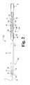
- FIG. 1is a perspective view of a surgical instrument according to one form of the present invention.
- FIG. 2is an exploded side view of a distal end portion of the surgical instrument depicted in FIG. 1 .
- FIG. 3is an exploded side view of a proximal end portion of the surgical instrument depicted in FIG. 1 .
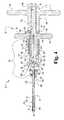
- FIG. 4is a broken cross-sectional side view of the surgical instrument depicted in FIG. 1 .
- FIG. 5is a perspective view of the distal end portion of the surgical instrument depicted in FIG. 1, as shown in an initial configuration.
- FIG. 6is a perspective view of the distal end portion depicted in FIG. 5, as shown in a deformed configuration.
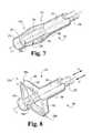
- FIG. 7is a perspective view of the distal end portion of a surgical instrument according to another form of the present invention, as shown in an initial configuration.
- FIG. 8is a perspective view of the distal end portion depicted in FIG. 7, as shown in a deformed configuration.
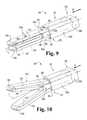
- FIG. 9is a perspective view of the distal end portion of a surgical instrument according to another form of the present invention, as shown in an initial collapsed configuration.
- FIG. 10is a perspective view of the distal end portion depicted in FIG. 9, as shown in a partially expanded configuration.
- FIG. 11is a perspective view of the distal end portion depicted in FIG. 9, as shown in a fully expanded configuration.
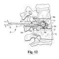
- FIG. 12is a partial cross-sectional side view of a spinal column illustrating treatment of a vertebral body using the surgical instrument illustrated in FIG. 1 .
- instrument 20for treatment of the spine according to one form of the present invention.
- Instrument 20is particularly useful for placement adjacent a spinal structure and selective displacement of at least a portion of the spinal structure.
- the spinal structureis a vertebral body.
- instrument 20may be used in intrabody applications such as, for example, a vertebral plasty procedure to compact cancellous bone within the vertebral body and/or to reduce a compression fracture of the vertebral body.
- instrument 20may be used in interbody applications such as, for example, to distract a space between adjacent vertebral bodies, such as the vertebral disc space.
- the spinal structuremay be comprised of a spinal implant such as, for example, a cage device, or any other structure used in association with treatment of the spine.
- a spinal implantsuch as, for example, a cage device, or any other structure used in association with treatment of the spine.
- instrument 20is illustrated and described in the context of treatment of a human spine, it should be understood that instrument 20 may be used to treat other animals. It should further be understood that instrument 20 may be used in association with applications outside of the spinal field such as, for example, to treat other types of bony structures.
- Instrument 20is generally comprised of an elongate member 22 extending generally along a longitudinal axis L and having a distal end portion 22 a and a proximal end portion 22 b. Although the illustrated embodiment depicts elongate member 22 as having a generally linear, unitary configuration, it should be understood that elongate member 22 may take on other configurations as well, such as, for example, a curvilinear configuration or a hinged configuration. Instrument 20 also includes an actuator mechanism 24 coupled to the proximal end portion 22 b of elongate member 22 . As will be discussed in greater detail below, the distal end portion 22 a is deformable and is configured to outwardly expand in response to a mechanically induced force. Such force may be effected, for example, by the selective actuation of actuator mechanism 24 .
- the distal end portion 22 ais reformable between an initial configuration (FIG. 5) and a deformed configuration (FIG. 6 ).
- initial configurationis broadly defined to encompass a structural configuration of elongate member 22 that is suitable for placement adjacent a spinal structure
- deformed configurationis broadly defined to encompass a structural configuration of elongate member 22 that is suitable for displacement of at least a portion of the spinal structure.
- the spinal structureis a vertebral body, and displacement of the vertebral body could be associated with either intrabody or interbody applications.
- the elongate member 22is comprised of an inner rod member 30 and an outer sleeve member 32 .
- the inner rod 30is preferably formed of a substantially rigid medical grade material such as, for example, titanium or stainless steel.
- the distal end portion 30 a of rod 30includes a tapered portion 34 , a reduced cross-section intermediate portion 36 , and a rounded distal end portion 38 .
- the intermediate portion 36has a diameter somewhat smaller than the diameter of the tapered portion 34 and the rounded distal end portion 38 so as to define a pair of opposing shoulders 40 , 42 .
- rod 30has been illustrated and described as having a substantially circular cross section, it should be understood that other shapes and configurations are also contemplated as being within the scope of the invention including, for example, elliptical, square, rectangular or other polygonal configurations.
- the outer sleeve 32preferably has a tubular configuration defining an inner passage extending therethrough generally along longitudinal axis L and sized to slidably receive rod 30 .
- Sleeve 32is preferably formed of a flexible material that is capable of facilitating deformation from an initial configuration toward a deformed configuration. Additionally, sleeve 32 is preferably formed of an elastic material that is capable of facilitating elastic deformation from the initial configuration toward the deformed configuration and reformation back toward the initial configuration.
- Sleeve 32may be formed of materials including, but not limited to, titanium, stainless steel, an elastomer, a polymer, a rubber, a composite material or a shape-memory material.
- sleeve 32may be formed of a flexible, elastic material, it should be understood that only the distal end portion 32 a of sleeve 32 need be formed of such material, with the remainder of sleeve 32 being formed of any suitable medical grade material.
- outer sleeve 32is illustrated as having a substantially tubular configuration, it should be understood that other shapes and configurations of sleeve 32 are also contemplated as being within the scope of the present invention.
- sleeve 32has been illustrated and described as being formed as a single-piece, unitary structure, it should be understood that the distal end portion 32 a could be formed separately from the remainder of sleeve 32 , and coupled together by any known method, such as, for example, by fastening, welding or adhesion.
- the distal end portion 32 a of sleeve 32includes at least one slot 50 extending generally along longitudinal axis L, and preferably includes at least a pair of slots 50 and 52 (not shown) disposed generally opposite one another so as to define a pair of longitudinally extending flexible strips of material 54 , 56 . It should be understood, however, that the distal end portion 32 a of sleeve 32 could be configured to define any number of longitudinally extending slots, including three or more slots, which would in turn define a corresponding number of longitudinally extending flexible strips of material. It should further be understood that distal end portion 32 a may include a number of slots disposed at various axial locations along longitudinal axis L. As will be described below, the slots 50 , 52 are provided to facilitate outward buckling of the distal end portion 32 a of sleeve 32 in at least one predetermined direction upon the selective actuation of the actuator mechanism 24 .
- slots 50 , 52are substantially identical in shape and configuration, and thus only slot 50 will be described in detail. However, it should be understood that slots 50 , 52 may take on different shapes and configurations. Slots 50 , 52 and strips of material 54 , 56 are illustrated as having a predetermined shape to provide a degree of control over the outward buckling of the strips of material 54 , 56 . In one embodiment of the invention, the slots 50 , 52 and strips of material 54 , 56 have an irregular shape. Slot 50 includes a relatively narrow and straight slot portion 60 , a first hourglass-shaped slot portion 62 formed by a first series of arcuate portions, and a second hourglass-shaped slot portion 64 formed by a second series of arcuate portions. As will become apparent below, the widened areas of the hourglass-shaped portions 62 and 64 serve as bending or flexion points to control the outward deformation of the flexible strips of material 54 , 56 .
- the straight slot portion 60extends longitudinally from the distal end of sleeve 32 .
- the first hourglass-shaped portion 62extends longitudinally from slot portion 60 and includes a first widened area 62 a, a narrowed area 62 b, and a second widened area 62 c.
- the second hourglass-shaped portion 64extends longitudinally from the first hourglass-shaped portion 62 and includes a first widened area 64 a, a narrow area 64 b , and a second widened area 64 c.
- the distal end portion 32 a of sleeve 32is secured to the inner rod 30 by way of a compression ring 70 .
- the distal-most portion of sleeve 32is disposed about portion 36 of rod 30 , with the distal end of sleeve 32 abutting the shoulder 42 formed by the rounded distal end portion 38 .
- the compression ring 70is positioned about the distal-most portion of sleeve 32 and is compressed thereabout, such as, for example, by mechanical crimping to secure sleeve 32 to inner rod 30 .
- slot portion 60aids in tightly compressing sleeve 32 about inner rod 30 to provide secure engagement therebetween.
- compression ring 70could alternatively be compressed about distal-most portion of sleeve 32 by other means, such as, for example, by forming compression ring 70 out of a shape-memory material that is reformable to a memorized configuration having an internal diameter that is less than the outer diameter of sleeve 32 . It should further be understood that the distal-most end portion of sleeve 32 could be secured to rod 30 by other means, such as, for example, by fastening, welding, adhesion or other methods of attachment known to those of skill in the art.
- Actuator mechanism 24is generally comprised of a rotary handle 100 , a stationary handle 102 , a connector assembly 104 , and an actuator member 106 .
- the connector assembly 104is configured to secure the elongate member 22 , and more specifically the outer sleeve 32 , to the remainder of the actuator mechanism 24 .
- the threaded actuator member 106is coupled to the inner rod 30 and is engaged with the rotary handle 100 such that rotational displacement of handle 100 about longitudinal axis L linearly displaces the actuator member 106 along longitudinal axis L.
- the linear displacement of rod 30 relative to sleeve 32causes the distal end portion 32 a of sleeve 32 to reform from its initial configuration toward its deformed configuration.
- the rotary handle 100includes a pair of lateral extensions 110 , 112 extending outwardly from a main body portion 114 to define a T-handle arrangement which aids the surgeon in rotating the handle 100 relative to the stationary handle 102 .
- the main body portion 114includes an opening extending along longitudinal axis L and having a threaded portion 116 and an unthreaded portion 118 .
- a hub portion 120extends from the main body portion 114 and defines an annular groove 122 .
- the stationary handle 102includes a pair lateral extensions 130 , 132 extending outwardly from a main body portion 134 to define a second T-handle arrangement which aids the surgeon in securely gripping instrument 20 and in maintaining the handle 102 in a stationary rotational position during rotation of handle 100 .
- the main body portion 134includes an opening extending therethrough along longitudinal axis L and defining a first cavity 136 and a second cavity 138 .
- a pair of openings 140 , 142extend through the main body portion 134 and are disposed in communication with the first cavity 136 .
- the hub portion 120 of handle 100is inserted within the first cavity 136 and a pin or fastener 148 is inserted through opening 140 and positioned within the annular groove 122 to axially couple rotary handle 100 to stationary handle 102 while permitting relative rotational displacement therebetween.
- the actuator member 106includes a threaded shank portion 150 and an unthreaded shank portion 152 .
- the threaded shank portion 150is configured to threadingly engage the threaded opening 116 in rotary handle 100 .
- the threaded shank portion 150 and the threaded opening 116each define right hand threads.
- the unthreaded shank portion 152includes a slotted opening 154 extending therethrough that is aligned with the opening 142 in the stationary handle 102 .
- a pin or fastener 155is inserted through the opening 142 and the slotted opening 154 to couple the actuator member 106 to the stationary handle 102 .
- pin 155substantially prevents relative rotational displacement between actuator member 106 and handle 102 while allowing a limited amount of relative linear displacement along longitudinal axis L.
- the distal end portion of the actuator member 106includes a socket 156 configured to accept a corresponding ball portion 158 extending from the proximal end portion 30 b of rod 30 .
- the socket opening 156includes a spherical portion 160 sized to receive the ball portion 158 therein, and a cylindrical portion 162 sized to receive the distal end portion 30 b of rod 30 therethrough to connect rod 30 to actuator member 106 . It should be understood, however, that other methods of interconnecting rod 30 and actuator member 106 are also contemplated as would occur to one of skill in the art.
- the connector assembly 104is configured to connect the elongate member 22 , and more specifically the outer sleeve 32 , to the remainder of the actuator mechanism 24 .
- the connector assembly 104is generally comprised of a gripper member 170 , a lock collar member 172 and a biasing member 174 .
- the gripper member 170includes a connecting segment 176 , a gripping segment 178 and a longitudinal passage having a first portion 180 extending through connecting segment 176 and a second portion 181 extending through the gripping segment 178 .
- the first portion 180 of the passageis sized to receive the shank portion 152 of actuator member 150 therein, and the second portion 181 of the passage is sized to receive the proximal end portion 32 b of sleeve 32 therein.
- the gripping segment 178 of gripper member 170has a generally conical shape and includes a tapered outer surface 182 .
- the gripping segment 178also includes a longitudinally extending slit 183 and a pair of transverse slots 184 that intersect slit 183 , with both the slit 183 and the slots 184 intersecting the longitudinal passage 181 .
- One purpose of the slit 183 and the slots 184is to facilitate compression of the gripping segment 178 about the proximal end portion 32 b of sleeve 32 .
- the proximal end portion 32 b of sleeve 32defines an opening or window 185 extending therethrough to further facilitate gripping of sleeve 32 by gripping segment 178 .
- slit 183Another purpose of slit 183 is to provide a passageway for the lateral insertion of the proximal end portion 30 b of rod 30 therethrough to permit assembly with the actuator member 106 .
- the gripping segment 178also includes an outer tapered surface 186 , the purpose of which will become evident below.
- the connecting segment 176 of gripper member 170defines an elongate opening 187 extending transversely therethrough and being positioned in communication with the longitudinal slit 183 .
- One purpose of the elongate opening 187is to facilitate compression of the gripping segment 178 about the proximal end portion 32 b of sleeve 32 .
- Another purpose of the transverse slot 187is to provide a passageway for the lateral insertion of the ball portion 158 of rod 30 therethrough and into engagement with the socket 156 defined in actuator member 106 .
- the connecting segment 176also includes an opening 188 extending transversely therethrough and aligned with the opening 142 in the stationary handle 102 . Pin 155 is inserted through the opening 188 to axially couple the gripper member 170 , and in turn the elongate member 22 , to the stationary handle 102 in a manner that substantially prevents relative linear and rotational displacement therebetween.
- the lock collar member 172includes a cylindrically-shaped body portion 190 , a tapered end portion 192 , and a longitudinal passage 194 extending therethrough and being sized to receive the connecting segment 176 of gripper member 170 therein.
- the cylindrical body portion 190is sized to be received within cavity 138 of stationary handle 102 .
- the longitudinal passage 194includes an inner tapered surface 196 that corresponds to the outer tapered surface 186 of gripping segment 178 .
- the biasing member 174is a coil spring. However, it should be understood that other types of biasing devices may alternatively be used as would occur to one of skill in the art.
- spring 174is disposed within the cavity 138 of stationary handle 102 and is engaged against the proximal end of the lock collar 172 to bias the lock collar 172 toward the gripping segment 178 .
- the biasing of lock collar 172engages the tapered inner surface 196 tightly against the tapered outer surface 186 of gripping segment 178 .
- Such engagementcreates an inward compression force onto the gripping segment 178 which causes the gripping segment 178 to collapse tightly about the proximal end portion 32 b of sleeve 32 to securely grip sleeve 32 within the longitudinal passage 181 .
- the tapered outer surface 192 of lock collar 172is oriented at about the same angle as the tapered outer surface 182 of gripping segment 178 to provide a relatively smooth transition between lock collar 172 and gripping segment 178 .
- actuator mechanism 24Although one specific embodiment of the actuator mechanism 24 has been illustrated and described herein, it should be understood that the use of other types and configurations of actuator mechanisms are also contemplated as would occur to one of skill in the art. As should be apparent, any type of actuator mechanism that is capable of imparting relative displacement between rod 30 and sleeve 32 to reform the distal end portion 32 a of sleeve 32 between the initial and deformed configurations may be used. It should further be understood that in an alternative form of the invention, rod 30 may be manually displaced by the surgeon relative to sleeve 32 , thereby eliminating the need for a separate actuator mechanism 24 .
- the distal end portion 22 a of elongate member 22As shown in an initial insertion configuration and a mechanically deformed expanded configuration, respectively.
- the distal end portion 32 a of sleeve 32When in the initial configuration (FIG. 5 ), the distal end portion 32 a of sleeve 32 has a relatively low profile to facilitate positioning adjacent a vertebral body.
- the rounded distal end portion 38reduces the likelihood of damage to adjacent tissue during such positioning.
- positioning of the distal end portion 32 a adjacent a vertebral bodyis meant to include positioning of the distal end portion 32 a in proximity to a vertebral body, within a vertebral body or within a space between adjacent vertebral bodies.
- instrument 20may also be used in association with spinal structures other than a vertebral body, such as, for example, a spinal implant, with the distal end portion 32 a of sleeve 32 being positioned adjacent or within the spinal implant when in the insertion configuration.
- spinal structuresother than a vertebral body, such as, for example, a spinal implant, with the distal end portion 32 a of sleeve 32 being positioned adjacent or within the spinal implant when in the insertion configuration.
- the distal end portion 32 a of sleeve 32is mechanically deformed by displacing the rod 30 relative to the sleeve 32 .
- such relative displacementis accomplished by linearly displacing rod 30 relative to sleeve 32 in the direction of arrow A, and is initiated by the selective actuation of actuator mechanism 24 .
- the distal end portion 32 a of sleeve 32may be mechanically deformed toward the expanded configuration by way of relative rotational displacement between rod 30 and sleeve 32 .
- the distal end portion 32 a of sleeve 32When reformed toward the expanded configuration (FIG. 6 ), the distal end portion 32 a of sleeve 32 is outwardly deformed relative to longitudinal axis L so as to form a number of laterally extending projections or protrusions 198 a , 198 b.
- the deformed configuration of instrument 20may define any number of laterally extending projections, including a single projection or three or more projections, and may define a number of laterally extending projections at various axial locations along longitudinal axis L. It should be apparent that the number, position, and direction of the laterally extending projections is at least partially controlled by the configuration and placement of the slots 50 in sleeve 32 .
- the distal end portion 32 a of sleeve 32may be reformed from its deformed/expanded configuration back toward its initial insertion configuration by linearly displacing rod 30 relative to sleeve 32 in the direction of arrow B.
- the distal end portion 32 a of sleeve 32may be formed of a shape-memory material, such as, for example, a shape-memory alloy (“SMA”) to aid in reforming the distal end portion 32 a from the deformed configuration back toward its initial configuration.
- SMAshape-memory alloy
- SMAsare known to exhibit a characteristic or behavior in which a particular component formed of an SMA is capable of being deformed from an initial “memorized” shape or configuration to a different shape or configuration, and then reformed back toward its initial shape or configuration.
- the ability to possess a shape-memory characteristic or behavioris a result of the fact that the SMA undergoes a reversible transformation from an austenitic state to a martensitic state. If the martensitic transformation occurs due to the imposition of stress, the shape-memory phenomena is referred to as stress-induced martensitic transformation.
- SMAsare known to display a superelastic or rubber-like behavior in which a strain attained beyond the elastic limit of the SMA material during loading is recovered during unloading. This superelastic phenomena occurs when stress is applied to an SMA article at a temperature slightly higher than the temperature at which the SMA begins to transform into austenite (sometimes referred to as the transformation temperature or A s ).
- the articleWhen stressed, the article first deforms elastically up to the yield point of the SMA material (sometimes referred to as the critical stress). However, upon the further imposition of stress, the SMA material begins to transform into stress-induced martensite. This transformation takes place at an essentially constant stress, up to the point where the SMA material is completely transformed into martensite. When the stress is removed, the SMA material will revert back into austenite and the article will automatically return toward its original, pre-programmed or memorized shape without a corresponding change in temperature.
- the critical stresssometimes referred to as the critical stress
- Nitinol®has a very low corrosion rate and excellent wear resistance, thereby providing an advantage when used as a support structure within the human body. Additionally, implant studies in animals have shown minimal elevations of nickel in the tissues in contact with the Nitinol® material. It should be understood, however, that other SMA materials that exhibit superelastic characteristics are contemplated as being within the scope of the invention.
- distal end portion 32 b of outer sleeve 32is formed of an SMA material and is reshaped or deformed while at a temperature above the transformation temperature A s , of the SMA, the distal end portion 32 b will automatically recover or reform toward its initial shape or configuration when the stress is removed from distal end portion 32 b. As illustrated in FIG. 5, when distal end portion 32 b is in its unstressed initial configuration, virtually all of the SMA material will be in an austenitic state.
- At least a portion of the SMA materialwill transform into reversible stress-induced martensite as the distal end portion 32 b is deformed toward the expanded configuration.
- the reduction or removal of the stresse.g., by turning actuator handle 100 in a counter clockwise direction
- at least a portion of the SMA materialwill be transformed back into austenite and the distal end portion 32 b will automatically reform back toward the initial configuration.
- instrument 200shown therein is the distal end portion of an instrument 200 according to another form of the present invention, as shown in an initial insertion configuration and a mechanically deformed configuration, respectively. It should be understood that instrument 200 may be used in association with applications similar to those discussed above with regard to instrument 20 , including both intrabody and interbody applications involving displacement of at least a portion of a vertebral body.
- Instrument 200is generally comprised of an elongate member 222 extending along a longitudinal axis L and having a distal end portion (as shown) and a proximal end portion (not shown) coupled to an actuator mechanism which may be configured similar to actuator mechanism 24 .
- the distal end portion of elongate member 222is deformable and is configured to outwardly expand in response to a mechanically induced force. Specifically, the distal end portion is reformable between an initial configuration (FIG. 7) for positioning adjacent a vertebral body, and a deformed configuration (FIG. 8) for displacement of at least a portion of the vertebral body.
- elongate member 222may take on other configurations as well, such as, for example, a curvilinear configuration or a hinged configuration.
- the elongate member 222is generally comprised of an inner rod member 230 and an outer sleeve member 232 .
- the inner rod 230is preferably formed of a substantially rigid medical grade material such as, for example, titanium or stainless steel.
- the rod 230includes a distal end portion 230 a that is disposed within and coupled to a distal end portion 232 a of sleeve 232 .
- rod 230has been illustrated and described as having a substantially circular cross, it should be understood that other shapes and configurations are also contemplated as being within the scope of the present invention, such as, for example, elliptical, square, rectangular or other polygonal configurations.
- the outer sleeve 232preferably has a tubular configuration defining an inner passage extending therethrough generally along longitudinal axis L and sized to slidably receive rod 230 therein.
- Sleeve 232is formed of a relatively flexible material that is capable of being reformed from an initial configuration to an expanded configuration.
- sleeve 232is formed of a relatively elastic material that is capable of being elastically deformed to the expanded configuration and reformed back toward the initial configuration.
- Sleeve 232may be formed of materials including, but not limited to, titanium, stainless steel, an elastomer, a polymer, a rubber, a composite material or a shape-memory material.
- sleeve 232may be formed of a flexible, elastic material, it should be understood that only the distal end portion 232 a need be formed of such material, with the remainder of sleeve 232 being formed of any suitable medical grade material. Additionally, although sleeve 232 is illustrated as having a substantially cylindrical or tubular configuration, it should be understood that other shapes and configurations of sleeve 232 are also contemplated as being within the scope of the present invention.
- sleeve 232has been illustrated and described as being formed as a single-piece, unitary structure, it should be understood that the distal end portion 232 a could be formed separately from the remainder of sleeve 232 , and coupled together by any known method, such as, for example, by fastening, welding or adhesion.
- the distal-most end portion 270 of sleeve 232is secured to the distal end portion 230 a of rod 230 by way of crimping.
- sleeve portion 270may be connected to rod portion 230 a by a compression ring similar to compression ring 70 , or by other connection techniques such as, for example, fastening, welding, adhesion, or other methods of attachment known to those of skill in the art.
- the distal end portion 232 a of sleeve 232includes at least one rectangular-shaped window or slot 250 extending generally along longitudinal axis L, and preferably includes at least a pair of slots 250 and 252 (not shown) disposed generally opposite one another so as to define a pair of longitudinally extending flexible strips of material 254 , 256 .
- the distal end portion 232 a of sleeve 232could define any number of longitudinally extending slots, including three or more slots, which would in turn define a corresponding number of flexible strips of material disposed between the slots.
- the slots 250 , 252are provided to facilitate outward buckling of the distal end portion 232 a of sleeve 232 upon the imposition of relative linear displacement between rod 230 and sleeve 232 .
- the flexible strips of material 254 , 256will outwardly buckle along transverse axis T at a location adjacent the midpoint of slots 250 , 252 .
- the slots 250 , 252are substantially identical in shape and configuration. However, it should be understood that slots 250 , 252 may take on different predetermined shapes and configurations. Additionally, although slots 250 , 252 and strips of material 254 , 256 are illustrated as having a generally rectangular shape, other predetermined shapes and configurations are also contemplated.
- the distal end portion 232 a of sleeve 232When in the initial configuration (FIG. 7 ), the distal end portion 232 a of sleeve 232 has a relatively low profile to facilitate positioning adjacent a vertebral body. However, once properly positioned adjacent the vertebral body, the distal end portion 232 a is mechanically deformed by displacing rod 230 relative to sleeve 232 . In the illustrated embodiment, such relative displacement is accomplished by linearly displacing rod 230 relative to sleeve 232 in the direction of arrow A. In an alternative form of the present invention, the distal end portion 232 a of sleeve 232 may be mechanically deformed toward the expanded configuration by way of relative rotational displacement between rod 230 and sleeve 232 .
- the distal end portion 232 a of sleeve 232When reformed toward the expanded configuration (FIG. 8 ), the distal end portion 232 a of sleeve 232 is outwardly deformed relative to longitudinal axis L so as to form a number of laterally extending projections or protrusions 298 a, 298 b.
- the deformed/expanded configuration of instrument 200may alternatively define any number of laterally extending projections, including a single projection or three or more projections. Similar to instrument 20 , formation of the laterally extending projections and the resulting displacement of the vertebral body by instrument 200 is directionally-controlled, and can be uniaxial, unidirectional or both uniaxial and unidirectional.
- the distal end portion 232 a of sleeve 232may be reformed back toward its initial insertion configuration by linearly displacing rod 230 relative to sleeve 232 in the direction of arrow B.
- the distal end portion 232 a of sleeve 232may be formed of a shape-memory material, such as, for example, a shape-memory alloy to aid in reforming distal end portion 232 a back toward its initial configuration.
- a flexible membrane 280is covered by a flexible membrane 280 .
- the flexible membrane 280is preferably formed of a resilient material that is capable of conforming to the shape of the distal end portion 232 a of sleeve 232 during reformation between the initial and deformed configurations.
- Such flexible materialsinclude, but are not limited to, silicone, latex, rubber, a polymer or other suitable elastomeric materials.
- One purpose of the flexible membrane 280is to prevent tissue or other foreign material from passing through the slots 250 , 252 and being deposited within the space between the strips of material 254 , 256 and the rod 230 and/or between the rod 230 and the remainder of the sleeve 232 .
- such a build-up of tissue or foreign materialmay block or otherwise inhibit reformation of the distal end portion 232 a of sleeve 232 from the deformed configuration (FIG. 8) back toward the initial configuration (FIG. 7 ).
- the flexible membrane 280is illustrated as covering the distal end portion of elongate member 222 , it should be understood that the flexible membrane 280 could be sized to cover the entire length of the elongate member 222 . It should also be understood that a flexible membrane similar to flexible membrane 280 may be used in association with the surgical instrument 20 discussed above and/or the surgical instrument 300 discussed below.
- instrument 300shown therein is the distal end portion of an instrument 300 according to another form of the present invention, as shown in an initial insertion configuration, a partially deformed intermediate configuration, and a fully deformed configuration, respectively. It should be understood that instrument 300 may be used in association with applications similar to those discussed above with regard to instrument 20 , including both intrabody and interbody applications involving displacement of at least a portion of a vertebral body.
- Instrument 300is comprised of an elongate member 322 extending generally along a longitudinal axis L and having a distal end portion (as shown) and a proximal end portion (not shown) which may be coupled to an actuator mechanism similar to actuator mechanism.
- the distal end portionis deformable and is configured to outwardly expand upon the imposition of a mechanically induced force. Specifically, the distal end portion is reformable between an initial configuration (FIG. 9) for positioning adjacent a vertebral body, and a deformed configuration (FIG. 11) for displacement of at least a portion of the vertebral body.
- elongate member 322may take on other configurations as well, such as, for example, a curvilinear configuration or a hinged configuration.
- the elongate member 322is generally comprised of an inner rod member 330 and an outer sleeve member 332 .
- the inner rod 330is preferably formed of a substantially rigid medical grade material such as, for example, titanium or stainless steel.
- Rod 330includes a distal end portion 330 a extending from a main body portion 330 b.
- the distal end portion 330 ahas a rectangular shape and the main body portion 330 b has a square shape.
- other shapes and configurations of rod 330are also contemplated as being within the scope of the present invention such as, for example, circular, elliptical or polygonal configurations.
- the outer sleeve 332has a deformable distal end portion 332 a coupled to a main body portion 332 b.
- the main body portion 332 bhas a square configuration defining an inner passage extending therethrough generally along longitudinal axis L and sized to slidably receive portion 330 b of rod 330 therein.
- the main body portion 332 bis formed of a substantially rigid material, such as, for example, titanium, stainless steel or other substantially rigid medical grade materials.
- the deformable distal end portion 332 a of sleeve 332is at least partially formed of a relatively flexible material that is capable of being reformed from the initial configuration illustrated in FIG. 9 toward the deformed configuration illustrated in FIG. 11 .
- distal end portion 332 bis formed of a relatively elastic material that is capable of being elastically deformed toward the deformed configuration and reformed back toward the initial configuration.
- the deformable distal end portion 332 bmay be formed of materials including, but not limited to, titanium, stainless steel, an elastomer, a polymer, a rubber, a composite material or a shape-memory material.
- Distal end portion 332 bis preferably formed separately from main body portion 332 a and connected thereto by any method know to one of skill in the art, such as, for example, by fastening, welding or adhesion. However, is should be understood that distal end portion 332 b could alternatively be formed integral with main body portion 332 a to define a single-piece, unitary structure.
- the deformable distal end portion 332 a of sleeve 332includes a plurality of wall elements 354 - 357 that are flexibly interconnected by a number or interconnection portions 360 .
- the interconnection portions 360are defined by forming an opening or channel 362 at locations where adjacent wall elements adjoin to one another.
- the wall elements 354 - 357are integrally formed to define a unitary, single-piece reformable structure that is collapsible to define a relatively low-profile insertion configuration and expandable to define an outwardly deformed configuration.
- the distal end portion 332 a of sleeve 332is preferably flexibly coupled to the main body portion 332 b.
- the outer wall elements 354 , 355each include a flexible interconnection portion 366 defined by forming an opening or channel 367 adjacent their respective distal end portions 354 a , 355 a.
- the distal end portions 354 a, 355 a of the outer wall elements 354 , 355are in turn coupled to inner surfaces of the main body portion 332 b of sleeve 332 , such as, for example, by fastening, welding or adhesion.
- the outer wall elements 354 , 355are separated by a distance sufficient to receive the distal end portion 330 a of rod 330 therebetween.
- the insertion configurationhas a substantially rectangular-shaped profile, with each of the wall elements 354 - 357 being disposed in a substantially uniform orientation (i.e., parallel to one another), and with the two inner wall elements 356 , 357 being disposed between the two outer wall elements 354 , 355 .
- the deformed/expanded configurationhas a substantially triangular-shaped profile, with the two inner wall elements 356 , 357 being disposed in a substantially parallel and co-linear orientation, and the two outer wall elements 354 , 355 being disposed at an angle ⁇ relative to inner wall elements 356 , 357 .
- the angle ⁇is about 30°-45°.
- reformable distal end portion 332 b of sleeve 332has been illustrated and described as including four wall elements 354 - 357 , it should be understood that any number of wall elements may be flexibly interconnected to form the reformable distal end portion 332 b.
- the deformable distal end portion 332 a of sleeve 332When in the initial folded configuration illustrated in FIG. 9, the deformable distal end portion 332 a of sleeve 332 has a relatively low profile to facilitate positioning adjacent a vertebral body. However, once properly positioned adjacent the vertebral body, the distal end portion 332 a is mechanically deformed by displacing rod 330 relative to sleeve 332 . In the illustrated embodiment, such relative displacement is accomplished by linearly displacing rod 330 relative to sleeve 332 in the direction of arrow B, and is initiated by the selective actuation of an actuator mechanism (not shown).
- the wall elements 354 - 357are unfolded and expanded outwardly relative to longitudinal axis L so as to form laterally extending projections or protrusions 398 a, 398 b disposed along a transverse axis T.
- instrument 300has been illustrated and described as including a pair of oppositely disposed projections 398 a, 398 b when in the expanded configuration, it should be understood that the distal end portion 332 a of sleeve 332 may be configured to define any number of projections, including a single projection or three or more projections.
- the expansion of the distal end portion 332 a of sleeve 332 and the resulting displacement of the spinal structure accomplished by instrument 300is directionally-controlled, and can be uniaxial, unidirectional or both uniaxial and unidirectional.
- the distal end portion 332 a of sleeve 332may be reformed toward its initial insertion configuration by linearly displacing rod 330 relative to sleeve 332 in the direction of arrow A (FIG. 11 ).
- the distal end portion 332 a of sleeve 332may be formed of a shape-memory material, such as, for example, a shape-memory alloy (“SMA”) to aid in reforming distal end portion 332 a back toward its initial configuration.
- SMAshape-memory alloy
- FIG. 12shown therein is a lateral view of a spinal column, illustrating the introduction and expansion of instrument 20 within a vertebral body V 1 to perform intrabody distraction.
- the distal end portion 32 a of sleeve 30is initially passed through an access opening (not shown) extending through an outer wall of the vertebral body V 1 while in the undeformed initial configuration illustrated in FIG. 5 .
- the distal end portion 32 a of sleeve 32is reformed by a mechanically-induced force created by linearly displacing rod 30 relative to sleeve 32 in the direction of arrow A.
- the distal end portion 32 ais outwardly deformed to form opposing projections 198 a, 198 b extending along transverse axis T.
- Such outward deformationis particularly useful, for example, to compact or compress cancellous bone against the inner cortical wall of the vertebral body V 1 to form a cavity C therein.
- Compaction of the cancellous bonemay have the effect of exerting an outward force on the inner surface of the cortical wall, making it possible to elevate or push broken and/or compressed bone back to or near its original pre-fracture condition or another desired condition.
- the opposing projections 198 a, 198 bmay bear directly against the inner surface of the cortical bone to reduce a compression fracture in the vertebral body V 1 .
- access into the inner cancellous region of the vertebral body V 1is be accomplished by drilling a relatively small access opening through an outer wall of the vertebral body, such as, for example, through the pedicular region of the vertebral body V 1 .
- the undeformed initial configuration of the distal end portion 32 a of sleeve 30is sized to pass through the small access opening to gain access to the inner cancellous region of the vertebral body V 1 . In this manner, insertion of the distal end portion 32 a of sleeve 32 is accomplished in a minimally invasive manner.
- the initial configuration of the distal end portion 32 a of sleeve 32is sized to pass through an access opening having a diameter between about 1 millimeter and about 5 millimeters. In a specific embodiment, the initial configuration of the distal end portion 32 a is sized to pass through an access opening having a diameter of about 3 millimeters.
- the deformed configuration of the distal end portion 32 a of sleeve 30is sized to displace the vertebral body V 1 within a range of about 3 millimeters to about 15 millimeters. In a specific embodiment, the deformed configuration of the distal end portion 32 a is sized to displace the vertebral body V 1 about 10 millimeters.
- the instrument 20is capable of assuming a deformed configuration that is over three times greater than its initial configuration.
- ranges and specific sizes of the initial and deformed configurations of distal end potion 32 b of sleeve 32have been set forth above, it should be understood that such ranges and specific sizes are exemplary and are not intended to limit the scope of the present invention in any manner whatsoever.
- the distal end portion 32 a of sleeve 32is reformed toward its initial insertion configuration by displacing rod 30 relative to sleeve 32 in the direction of arrow B.
- the opposing projections 198 a, 198 bare inwardly deformed to the extent necessary to provide uninhibited removal of the distal end portion 32 a of sleeve 32 from the vertebral body V 1 .
- reformation of the instrument 20 back toward its initial insertion configurationmay be facilitated by forming the distal end portion 32 a of sleeve 32 from a shape-memory material.
- the cavity Cmay be filled with a biocompatible filling material, such as, for example, methylmethacrylate cement (e.g., bone cement), a structural implant, and/or a therapeutic substance to promote healing.
- a biocompatible filling materialsuch as, for example, methylmethacrylate cement (e.g., bone cement), a structural implant, and/or a therapeutic substance to promote healing.
- the filling materialprovides internal structural support to the vertebral body V 1 , and more particularly provides structural support to the cortical bone of the vertebral body V 1 .
- a cannula assembly 400may be used to provide minimally invasive access to the vertebral bodies V 1 , V 2 and/or the disc space D. As shown in FIG. 12, use of the cannula assembly 400 permits displacement of the vertebral body V 1 via insertion and manipulation of instrument 20 through a single working channel. Further details regarding a cannula assembly suitable for use in association with the present invention are disclosed in U.S. patent application Ser. No. 09/692,932 to Foley et al., filed on Oct. 20, 2000, the contents of which are incorporated herein by reference.
- the cannula assembly 400includes a cannula 402 having a distal end 402 a and defining an inner working channel 404 extending between the distal end 402 a and a proximal end (not shown).
- the length of the cannula 402is sized such that the proximal end (not shown) of the cannula 402 is positioned beyond the skin of the patient when the distal end 402 a is positioned adjacent the vertebral body V 1 .
- One advantageous feature of the cannula assembly 400is the relatively large cross section of the working channel 404 extending through cannula 402 .
- Such a large cross sectionpermits the surgeon to introduce a wide variety of instruments or tools into the working channel 404 , as well as the simultaneous introduction of two or more instruments or tools. Furthermore, the relatively large cross section of working channel 404 permits a wide range of motion of the instruments and tools.
- the cannula assembly 400may also include an endoscope assembly (not shown) mounted to the proximal end portion of the cannula 402 to provide remote visualization of the surgical site.
- the endoscope assemblymay include, for example, a viewing element 406 disposed within the working channel 404 of cannula 402 and having a distal end 406 a positioned adjacent the surgical site.
- the viewing element 406is preferably linearly and rotatably displaceable within the working channel 404 to provide a wide degree of visualization of the surgical site.
- the endoscope assemblymay also include an illumination element (not shown), a remote viewing apparatus such as an eyepiece (not shown), and/or irrigation and aspiration components (not shown) extending along viewing element 406 .
- the cannula assembly 400may also include a microscopic viewing system (not shown) mounted to the proximal end portion of the cannula 402 to provide microscopic visualization of the surgical site.
- a microscopic viewing systemsuitable for use in association with the present invention is described in U.S. patent application Ser. No. 09/815,693 to Foley et al., filed on Mar. 23, 2001, the contents of which are incorporated herein by reference.
- FIG. 12illustrates the use of instrument 20 to at least partially displace the vertebral body V 1
- instruments 200 and 300could alternatively be used to perform the technique.
- instruments 20 , 200 and 300may be used to perform interbody distraction of one or both of the adjacent vertebral bodies V 1 , V 2 , such as, for example, to increase the height of the disc space D.
- Interbody distraction of adjacent vertebral bodies V 1 , V 2may also be effective to increase the distance between corresponding portions of the vertebral bodies V 1 , V 2 .
- shimsmay be positioned between the deformable distal end portion 32 a of sleeve 32 and the vertebral bodies V 1 , V 2 to distribute the compressive force over a larger area to avoid puncturing or crushing of the brittle portions.
- FIG. 12uses a posterior surgical approach, other surgical approaches are also contemplated, such as, for example, anterior, lateral, and postero-lateral approaches.
Landscapes
- Health & Medical Sciences (AREA)
- Life Sciences & Earth Sciences (AREA)
- Orthopedic Medicine & Surgery (AREA)
- Surgery (AREA)
- Animal Behavior & Ethology (AREA)
- General Health & Medical Sciences (AREA)
- Biomedical Technology (AREA)
- Heart & Thoracic Surgery (AREA)
- Veterinary Medicine (AREA)
- Engineering & Computer Science (AREA)
- Public Health (AREA)
- Molecular Biology (AREA)
- Nuclear Medicine, Radiotherapy & Molecular Imaging (AREA)
- Medical Informatics (AREA)
- Transplantation (AREA)
- Physical Education & Sports Medicine (AREA)
- Cardiology (AREA)
- Oral & Maxillofacial Surgery (AREA)
- Vascular Medicine (AREA)
- Surgical Instruments (AREA)
- Prostheses (AREA)
Abstract
Description
Claims (51)
Priority Applications (9)
| Application Number | Priority Date | Filing Date | Title |
|---|---|---|---|
| AU2001284857AAU2001284857B2 (en) | 2000-08-11 | 2001-08-13 | Surgical instrumentation and method for treatment of the spine |
| CA002419196ACA2419196A1 (en) | 2000-08-11 | 2001-08-13 | Surgical instrumentation and method for treatment of the spine |
| JP2002518850AJP4883874B2 (en) | 2000-08-11 | 2001-08-13 | Surgical instruments and methods for treating the spinal column |
| AU8485701AAU8485701A (en) | 2000-08-11 | 2001-08-13 | Surgical instrumentation and method for treatment of the spine |
| EP01963945AEP1309280A2 (en) | 2000-08-11 | 2001-08-13 | Surgical instrumentation and method for treatment of the spine |
| US09/928,949US6676665B2 (en) | 2000-08-11 | 2001-08-13 | Surgical instrumentation and method for treatment of the spine |
| PCT/US2001/025291WO2002013700A2 (en) | 2000-08-11 | 2001-08-13 | Surgical instrumentation and method for treatment of the spine |
| US10/756,970US20040153064A1 (en) | 2000-08-11 | 2004-01-13 | Surgical instrumentation and method for treatment of the spine |
| US11/786,595US20070198013A1 (en) | 2000-08-11 | 2007-04-12 | Surgical instrumentation and method for treatment of the spine |
Applications Claiming Priority (2)
| Application Number | Priority Date | Filing Date | Title |
|---|---|---|---|
| US22449100P | 2000-08-11 | 2000-08-11 | |
| US09/928,949US6676665B2 (en) | 2000-08-11 | 2001-08-13 | Surgical instrumentation and method for treatment of the spine |
Related Child Applications (1)
| Application Number | Title | Priority Date | Filing Date |
|---|---|---|---|
| US10/756,970ContinuationUS20040153064A1 (en) | 2000-08-11 | 2004-01-13 | Surgical instrumentation and method for treatment of the spine |
Publications (2)
| Publication Number | Publication Date |
|---|---|
| US20020026197A1 US20020026197A1 (en) | 2002-02-28 |
| US6676665B2true US6676665B2 (en) | 2004-01-13 |
Family
ID=26918772
Family Applications (3)
| Application Number | Title | Priority Date | Filing Date |
|---|---|---|---|
| US09/928,949Expired - LifetimeUS6676665B2 (en) | 2000-08-11 | 2001-08-13 | Surgical instrumentation and method for treatment of the spine |
| US10/756,970AbandonedUS20040153064A1 (en) | 2000-08-11 | 2004-01-13 | Surgical instrumentation and method for treatment of the spine |
| US11/786,595AbandonedUS20070198013A1 (en) | 2000-08-11 | 2007-04-12 | Surgical instrumentation and method for treatment of the spine |
Family Applications After (2)
| Application Number | Title | Priority Date | Filing Date |
|---|---|---|---|
| US10/756,970AbandonedUS20040153064A1 (en) | 2000-08-11 | 2004-01-13 | Surgical instrumentation and method for treatment of the spine |
| US11/786,595AbandonedUS20070198013A1 (en) | 2000-08-11 | 2007-04-12 | Surgical instrumentation and method for treatment of the spine |
Country Status (6)
| Country | Link |
|---|---|
| US (3) | US6676665B2 (en) |
| EP (1) | EP1309280A2 (en) |
| JP (1) | JP4883874B2 (en) |
| AU (2) | AU2001284857B2 (en) |
| CA (1) | CA2419196A1 (en) |
| WO (1) | WO2002013700A2 (en) |
Cited By (281)
| Publication number | Priority date | Publication date | Assignee | Title |
|---|---|---|---|---|
| US20020022856A1 (en)* | 2000-08-14 | 2002-02-21 | Wesley Johnson | Transverse cavity device and method |
| US20020123807A1 (en)* | 1999-10-20 | 2002-09-05 | Cauthen Joseph C. | Spinal disc annulus reconstruction method and spinal disc annulus stent |
| US20030153976A1 (en)* | 1999-10-20 | 2003-08-14 | Cauthen Joseph C. | Spinal disc annulus reconstruction method and spinal disc annulus stent |
| US20030181983A1 (en)* | 1999-10-20 | 2003-09-25 | Cauthen Joseph C. | Spinal disc annulus reconstruction method and spinal disc annulus stent |
| US20040092918A1 (en)* | 2002-11-08 | 2004-05-13 | Harvey Jay | Hair treatment method |
| US20040102774A1 (en)* | 2002-11-21 | 2004-05-27 | Trieu Hai H. | Systems and techniques for intravertebral spinal stabilization with expandable devices |
| US20040116777A1 (en)* | 2002-12-13 | 2004-06-17 | Jeffrey Larson | Guided retractor and methods of use |
| US20040133280A1 (en)* | 2002-11-21 | 2004-07-08 | Trieu Hai H. | Systems and techniques for interbody spinal stabilization with expandable devices |
| US20040133204A1 (en)* | 2001-01-27 | 2004-07-08 | Davies John Bruce Clayfield | Expandable bone nails |
| US20040267269A1 (en)* | 2001-06-01 | 2004-12-30 | Middleton Lance M. | Tissue cavitation device and method |
| US20050038440A1 (en)* | 2002-12-13 | 2005-02-17 | Jeffrey Larson | Guided retractor and methods of use |
| US20050043737A1 (en)* | 1998-04-06 | 2005-02-24 | Kyphon Inc. | Structures for creating cavities in interior body regions |
| US20050090852A1 (en)* | 2000-04-07 | 2005-04-28 | Kyphon Inc. | Insertion devices and method of use |
| US20050113860A1 (en)* | 2003-07-11 | 2005-05-26 | Yaron Keidar | Trans-septal sheath with splitting dilating needle and method for its use |
| US20050113836A1 (en)* | 2003-11-25 | 2005-05-26 | Lozier Antony J. | Expandable reamer |
| US20050215862A1 (en)* | 2003-11-26 | 2005-09-29 | Jeffrey Larson | Guided retractor and methods of use |
| US20050216007A1 (en)* | 2004-03-29 | 2005-09-29 | Christian Woll | Orthopedic intramedullary fixation system |
| US20050234493A1 (en)* | 2004-03-31 | 2005-10-20 | Carr John P | Methods and devices for cavity creation in mammalian bone tissue |
| US20050278036A1 (en)* | 2004-06-09 | 2005-12-15 | Ceravic | Method for restoration of human or animal bone anatomy, and expansible prosthetic implant allowing implementation of this method |
| US20050283161A1 (en)* | 2004-06-16 | 2005-12-22 | Sdgi Holdings, Inc. | Constant lift cam spreader |
| US20060052788A1 (en)* | 2003-02-04 | 2006-03-09 | Thelen Sarah L | Expandable fixation devices for minimally invasive surgery |
| US20060106461A1 (en)* | 2004-11-12 | 2006-05-18 | Embry Jill M | Implantable vertebral lift |
| US20060116690A1 (en)* | 2004-02-12 | 2006-06-01 | Pagano Paul J | Surgical instrumentation and method for treatment of a spinal structure |
| US20060116689A1 (en)* | 2004-06-16 | 2006-06-01 | Sdgi Holdings, Inc. | Surgical instrumentation and method for treatment of a spinal structure |
| US20060155170A1 (en)* | 2002-12-13 | 2006-07-13 | Synthes Spine Company, Lp | Guided retractor and methods of use |
| US20060167553A1 (en)* | 1999-10-20 | 2006-07-27 | Anulex Technologies, Inc. | Spinal disc annulus reconstruction method and deformable spinal disc annulus stent |
| US20060184192A1 (en)* | 2005-02-11 | 2006-08-17 | Markworth Aaron D | Systems and methods for providing cavities in interior body regions |
| US20060184248A1 (en)* | 2005-02-17 | 2006-08-17 | Edidin Avram A | Percutaneous spinal implants and methods |
| US20060190083A1 (en)* | 2003-07-25 | 2006-08-24 | Uri Arnin | Elastomeric spinal disc nucleus replacement |
| US20060202242A1 (en)* | 2005-03-09 | 2006-09-14 | Sony Corporation | Solid-state imaging device |
| US20060241644A1 (en)* | 1998-08-14 | 2006-10-26 | Osorio Reynaldo A | Cavity formation device |
| US20060247648A1 (en)* | 2005-04-29 | 2006-11-02 | Sdgi Holdings, Inc. | Surgical instrument and method |
| US20070005093A1 (en)* | 2005-07-01 | 2007-01-04 | Cox John A | System for tissue dissection and retraction |
| US20070001981A1 (en)* | 2005-06-29 | 2007-01-04 | Nec Electronics Corporation | Driver unit including common level shifter circuit for display panel and nonvolatile memory |
| US20070049934A1 (en)* | 2005-02-17 | 2007-03-01 | Edidin Avram A | Percutaneous spinal implants and methods |
| US20070049935A1 (en)* | 2005-02-17 | 2007-03-01 | Edidin Avram A | Percutaneous spinal implants and methods |
| US20070055265A1 (en)* | 2005-08-16 | 2007-03-08 | Laurent Schaller | Devices For Limiting the Movement Of Material Introduced Between Layers Of Spinal Tissue |
| US20070061013A1 (en)* | 1999-10-20 | 2007-03-15 | Cauthen Iii Joseph C | Methods and devices for spinal disc annulus reconstruction and repair |
| US20070060935A1 (en)* | 2005-07-11 | 2007-03-15 | Schwardt Jeffrey D | Apparatus and methods of tissue removal within a spine |
| US20070060933A1 (en)* | 2005-07-11 | 2007-03-15 | Meera Sankaran | Curette heads |
| US20070067034A1 (en)* | 2005-08-31 | 2007-03-22 | Chirico Paul E | Implantable devices and methods for treating micro-architecture deterioration of bone tissue |
| US20070100348A1 (en)* | 1999-10-20 | 2007-05-03 | Cauthen Joseph C Iii | Apparatus and methods for the treatment of the intervertebral disc |
| US20070123877A1 (en)* | 2005-11-15 | 2007-05-31 | Aoi Medical, Inc. | Inflatable Device for Restoring Anatomy of Fractured Bone |
| WO2007011994A3 (en)* | 2005-07-15 | 2007-06-21 | Stout Medical Group Lp | Device and method for fibrous tissue repair |
| US20070149990A1 (en)* | 2005-07-11 | 2007-06-28 | Palmer Erika I | Apparatus and methods of tissue removal within a spine |
| US20070156245A1 (en)* | 1999-10-20 | 2007-07-05 | Cauthen Joseph C Iii | Method and apparatus for the treatment of the intervertebral disc annulus |
| US20070156242A1 (en)* | 2003-09-02 | 2007-07-05 | Lin Kwan K | Devices and methods for the treatment of bone fracture |
| US20070185497A1 (en)* | 1999-10-20 | 2007-08-09 | Cauthen Joseph C | Method and apparatus for the treatment of the intervertebral disc annulus |
| US20070198013A1 (en)* | 2000-08-11 | 2007-08-23 | Foley Kevin T | Surgical instrumentation and method for treatment of the spine |
| US20070213717A1 (en)* | 2006-02-14 | 2007-09-13 | Sdgi Holdings, Inc. | Biological fusion in the vertebral column |
| US20070213823A1 (en)* | 2006-02-14 | 2007-09-13 | Sdgi Holdings, Inc. | Treatment of the vertebral column |
| US20070213718A1 (en)* | 2006-02-14 | 2007-09-13 | Sdgi Holdings, Inc. | Treatment of the vertebral column |
| CN100340215C (en)* | 2005-09-19 | 2007-10-03 | 吴乃庆 | Bone dilator |
| US20070233076A1 (en)* | 2006-03-31 | 2007-10-04 | Sdgi Holdings, Inc. | Methods and instruments for delivering interspinous process spacers |
| US20070227547A1 (en)* | 2006-02-14 | 2007-10-04 | Sdgi Holdings, Inc. | Treatment of the vertebral column |
| WO2006113080A3 (en)* | 2005-04-18 | 2007-10-25 | St Francis Medical Tech Inc | Interspinous process implant having deployable wings and method of implantation |
| WO2006135555A3 (en)* | 2005-06-08 | 2007-12-06 | Accelerated Innovation Llc | Vertebral facet stabilizer |
| US20070282340A1 (en)* | 2005-02-17 | 2007-12-06 | Malandain Hugues F | Percutaneous spinal implants and methods |
| US20070299526A1 (en)* | 2005-02-17 | 2007-12-27 | Malandain Hugues F | Percutaneous spinal implants and methods |
| US20080009876A1 (en)* | 2006-07-07 | 2008-01-10 | Meera Sankaran | Medical device with expansion mechanism |
| US20080027433A1 (en)* | 2005-02-17 | 2008-01-31 | Kohm Andrew C | Percutaneous spinal implants and methods |
| US20080027552A1 (en)* | 1997-01-02 | 2008-01-31 | Zucherman James F | Spine distraction implant and method |
| US20080027553A1 (en)* | 1997-01-02 | 2008-01-31 | Zucherman James F | Spine distraction implant and method |
| US20080046087A1 (en)* | 2004-09-23 | 2008-02-21 | Zucherman James F | Interspinous process implant including a binder and method of implantation |
| US20080051894A1 (en)* | 2005-02-17 | 2008-02-28 | Malandain Hugues F | Percutaneous spinal implants and methods |
| US20080058730A1 (en)* | 2006-08-31 | 2008-03-06 | Cook Incorporated | Rotationally actuated fixation mechanism |
| US20080071376A1 (en)* | 2005-02-17 | 2008-03-20 | Kohm Andrew C | Percutaneous spinal implants and methods |
| US20080114364A1 (en)* | 2006-11-15 | 2008-05-15 | Aoi Medical, Inc. | Tissue cavitation device and method |
| US20080154305A1 (en)* | 2006-12-26 | 2008-06-26 | Warsaw Orthopedic, Inc. | Minimally invasive spinal distraction devices and methods |
| US20080177272A1 (en)* | 2005-03-21 | 2008-07-24 | Zucherman James F | Interspinous process implant having deployable wing and method of implantation |
| US20080177298A1 (en)* | 2006-10-24 | 2008-07-24 | St. Francis Medical Technologies, Inc. | Tensioner Tool and Method for Implanting an Interspinous Process Implant Including a Binder |
| US20080221505A1 (en)* | 2007-03-07 | 2008-09-11 | Andres Betts | Expandable Blade Device for Stabilizing Compression Fractures |
| US20080269766A1 (en)* | 2007-04-30 | 2008-10-30 | Warsaw Orthopedic, Inc. | Intravertebral reduction device with retention balls |
| US20080272173A1 (en)* | 2000-09-08 | 2008-11-06 | Abbott Vascular Inc. | Surgical stapler |
| US20080294166A1 (en)* | 2007-05-21 | 2008-11-27 | Mark Goldin | Extendable cutting member |
| US20080294168A1 (en)* | 2007-05-23 | 2008-11-27 | Stryker Trauma Gmbh | Reaming device |
| US20080300636A1 (en)* | 2007-02-14 | 2008-12-04 | Olivier Carli | Fracture reduction instrument for osseous body |
| US20090005782A1 (en)* | 2007-03-02 | 2009-01-01 | Chirico Paul E | Fracture Fixation System and Method |
| WO2007147093A3 (en)* | 2006-06-16 | 2009-04-23 | Kyphon Sarl | Percutaneous spinal implants and methods |
| US20090131867A1 (en)* | 2007-11-16 | 2009-05-21 | Liu Y King | Steerable vertebroplasty system with cavity creation element |
| US20090131950A1 (en)* | 2007-11-16 | 2009-05-21 | Liu Y King | Vertebroplasty method with enhanced control |
| US20090131886A1 (en)* | 2007-11-16 | 2009-05-21 | Liu Y King | Steerable vertebroplasty system |
| US20090149860A1 (en)* | 2005-07-07 | 2009-06-11 | Scribner Robert M | Device for delivery of bone void filling materials |
| US20090149956A1 (en)* | 2006-05-01 | 2009-06-11 | Stout Medical Group, L.P. | Expandable support device and method of use |
| US20090163872A1 (en)* | 2007-12-19 | 2009-06-25 | Cook Incorporated | Bone cement needle |
| US20090177206A1 (en)* | 2008-01-08 | 2009-07-09 | Zimmer Spine, Inc. | Instruments, implants, and methods for fixation of vertebral compression fractures |
| US20090182427A1 (en)* | 2007-12-06 | 2009-07-16 | Osseon Therapeutics, Inc. | Vertebroplasty implant with enhanced interfacial shear strength |
| US20090198338A1 (en)* | 2008-02-04 | 2009-08-06 | Phan Christopher U | Medical implants and methods |
| US20090198241A1 (en)* | 2008-02-04 | 2009-08-06 | Phan Christopher U | Spine distraction tools and methods of use |
| US20090216260A1 (en)* | 2008-02-20 | 2009-08-27 | Souza Alison M | Interlocking handle |
| US20090270893A1 (en)* | 2008-04-25 | 2009-10-29 | Greg Arcenio | Medical device for tissue disruption with serrated expandable portion |
| US20090270862A1 (en)* | 2008-04-25 | 2009-10-29 | Greg Arcenio | Medical device with one-way rotary drive mechanism |
| US20090270892A1 (en)* | 2008-04-25 | 2009-10-29 | Greg Arcenio | Steerable medical device for tissue disruption |
| US20090276048A1 (en)* | 2007-05-08 | 2009-11-05 | Chirico Paul E | Devices and method for bilateral support of a compression-fractured vertebral body |
| US20090287244A1 (en)* | 2008-05-16 | 2009-11-19 | Abbott Laboratories Vascular Enterprises Limited | Apparatus and methods for engaging tissue |
| US20090299282A1 (en)* | 2007-11-16 | 2009-12-03 | Osseon Therapeutics, Inc. | Steerable vertebroplasty system with a plurality of cavity creation elements |
| US20100016905A1 (en)* | 2007-03-12 | 2010-01-21 | Stout Medical Group, L.P. | Expandable attachment device and method |
| US20100036381A1 (en)* | 2008-08-07 | 2010-02-11 | Ryan Vanleeuwen | Cavity creator with integral cement delivery lumen |
| US20100069913A1 (en)* | 2005-08-31 | 2010-03-18 | Chirico Paul E | Threaded bone filling material plunger |
| US20100114156A1 (en)* | 2008-10-30 | 2010-05-06 | Abbott Vascular Inc. | Closure device |
| US20100161060A1 (en)* | 2008-12-23 | 2010-06-24 | Benvenue Medical, Inc. | Tissue Removal Tools And Methods Of Use |
| US20100168748A1 (en)* | 2008-07-16 | 2010-07-01 | Knopp Peter G | Morselizer |
| US20100179567A1 (en)* | 2009-01-09 | 2010-07-15 | Abbott Vascular Inc. | Closure devices, systems, and methods |
| US20100179590A1 (en)* | 2009-01-09 | 2010-07-15 | Abbott Vascular Inc. | Vessel closure devices and methods |
| US20100179572A1 (en)* | 2009-01-09 | 2010-07-15 | Abbott Vascular Inc. | Closure devices, systems, and methods |
| US20100217132A1 (en)* | 2009-02-26 | 2010-08-26 | Abbott Laboratories | Methods and apparatus for locating a surface of a body lumen |
| US20100217335A1 (en)* | 2008-12-31 | 2010-08-26 | Chirico Paul E | Self-expanding bone stabilization devices |
| US20100274290A1 (en)* | 2006-06-29 | 2010-10-28 | Searete Llc, A Limited Liability Corporation Of The State Of Delaware | Position augmenting mechanism |
| US20100286701A1 (en)* | 2009-05-08 | 2010-11-11 | Kyphon Sarl | Distraction tool for distracting an interspinous space |
| US20110004308A1 (en)* | 2009-06-17 | 2011-01-06 | Marino James F | Expanding intervertebral device and methods of use |
| US20110015549A1 (en)* | 2005-01-13 | 2011-01-20 | Shimon Eckhouse | Method and apparatus for treating a diseased nail |
| US20110054416A1 (en)* | 2007-09-14 | 2011-03-03 | Hollowell Daniel R | Material control device for inserting material into a targeted anatomical region |
| US20110054492A1 (en)* | 2009-08-26 | 2011-03-03 | Abbott Laboratories | Medical device for repairing a fistula |
| US7935147B2 (en) | 1999-10-20 | 2011-05-03 | Anulex Technologies, Inc. | Method and apparatus for enhanced delivery of treatment device to the intervertebral disc annulus |
| US7955392B2 (en) | 2006-12-14 | 2011-06-07 | Warsaw Orthopedic, Inc. | Interspinous process devices and methods |
| US20110137319A1 (en)* | 1998-08-14 | 2011-06-09 | Kyphon Sarl | Systems and Methods for Reducing Fractured Bone Using a Fracture Reduction Cannula With a Side Discharge Port |
| US20110144766A1 (en)* | 2008-06-19 | 2011-06-16 | Shreedhar Kale | Allograft Bone Plugs, Systems and Techniques |
| US7993342B2 (en) | 2005-02-17 | 2011-08-09 | Kyphon Sarl | Percutaneous spinal implants and methods |
| US20110202096A1 (en)* | 2010-02-12 | 2011-08-18 | John White | Spinal Rod and Screw Securing Apparatus and Method |
| US20110218585A1 (en)* | 2010-03-08 | 2011-09-08 | Krinke Todd A | Apparatus and methods for bone repair |
| US20110224495A1 (en)* | 2010-03-12 | 2011-09-15 | Tyco Healthcare Group Lp | Surgical access port |
| US8096994B2 (en) | 2005-02-17 | 2012-01-17 | Kyphon Sarl | Percutaneous spinal implants and methods |
| US8114131B2 (en) | 2008-11-05 | 2012-02-14 | Kyphon Sarl | Extension limiting devices and methods of use for the spine |
| US8128698B2 (en) | 1999-10-20 | 2012-03-06 | Anulex Technologies, Inc. | Method and apparatus for the treatment of the intervertebral disc annulus |
| US8142462B2 (en) | 2004-05-28 | 2012-03-27 | Cavitech, Llc | Instruments and methods for reducing and stabilizing bone fractures |
| US8163022B2 (en) | 2008-10-14 | 2012-04-24 | Anulex Technologies, Inc. | Method and apparatus for the treatment of the intervertebral disc annulus |
| US20120136448A1 (en)* | 2008-08-29 | 2012-05-31 | Jody L Seifert | Devices and Methods for Treating Bone |
| US8202304B2 (en) | 2002-08-21 | 2012-06-19 | Theken Spine, Llc | Methods and systems for performing spinal surgery |
| US8221420B2 (en) | 2009-02-16 | 2012-07-17 | Aoi Medical, Inc. | Trauma nail accumulator |
| US8287538B2 (en) | 2008-01-14 | 2012-10-16 | Conventus Orthopaedics, Inc. | Apparatus and methods for fracture repair |
| US8366773B2 (en) | 2005-08-16 | 2013-02-05 | Benvenue Medical, Inc. | Apparatus and method for treating bone |
| US8393330B2 (en) | 2003-08-26 | 2013-03-12 | Harvey H. Jay | Hair treatment system and method |
| US8454617B2 (en) | 2005-08-16 | 2013-06-04 | Benvenue Medical, Inc. | Devices for treating the spine |
| US20130144391A1 (en)* | 2010-07-15 | 2013-06-06 | Nlt Spine Ltd | Surgical systems and methods for implanting deflectable implants |
| US8460319B2 (en) | 2010-01-11 | 2013-06-11 | Anulex Technologies, Inc. | Intervertebral disc annulus repair system and method |
| US8535327B2 (en) | 2009-03-17 | 2013-09-17 | Benvenue Medical, Inc. | Delivery apparatus for use with implantable medical devices |
| US8591583B2 (en) | 2005-08-16 | 2013-11-26 | Benvenue Medical, Inc. | Devices for treating the spine |
| US20130317617A1 (en)* | 2012-04-30 | 2013-11-28 | Peter L. Mayer | Unilaterally placed expansile spinal prosthesis |
| TWI418327B (en)* | 2011-06-03 | 2013-12-11 | Kabo Tool Co | Medical electric drill |
| WO2014028146A1 (en)* | 2012-08-17 | 2014-02-20 | Warsaw Orthopedic, Inc. | Spinal implant system and method |
| EP2724680A1 (en) | 2012-10-23 | 2014-04-30 | Spirit Spine Holdings Corporation, Inc. | Device for bone fixation |
| US8764803B2 (en) | 2012-10-04 | 2014-07-01 | Loubert S. Suddaby | Apparatus and method for aligning a spine |
| US20140187939A1 (en)* | 2012-10-10 | 2014-07-03 | Olympus Medical Systems Corp. | Treatment instrument |
| US8814873B2 (en) | 2011-06-24 | 2014-08-26 | Benvenue Medical, Inc. | Devices and methods for treating bone tissue |
| US8821506B2 (en) | 2006-05-11 | 2014-09-02 | Michael David Mitchell | Bone screw |
| US8840617B2 (en) | 2010-02-26 | 2014-09-23 | Warsaw Orthopedic, Inc. | Interspinous process spacer diagnostic parallel balloon catheter and methods of use |
| US8906022B2 (en) | 2010-03-08 | 2014-12-09 | Conventus Orthopaedics, Inc. | Apparatus and methods for securing a bone implant |
| US8926633B2 (en) | 2005-06-24 | 2015-01-06 | Abbott Laboratories | Apparatus and method for delivering a closure element |
| US8956388B2 (en) | 2000-01-05 | 2015-02-17 | Integrated Vascular Systems, Inc. | Integrated vascular device with puncture site closure component and sealant |
| US8961518B2 (en) | 2010-01-20 | 2015-02-24 | Conventus Orthopaedics, Inc. | Apparatus and methods for bone access and cavity preparation |
| US8986386B2 (en) | 2009-03-12 | 2015-03-24 | Vexim Sas | Apparatus for bone restoration of the spine and methods of use |
| US20150094815A1 (en)* | 2012-05-30 | 2015-04-02 | Newvert Ltd. | Spinal disc annulus closure device |
| US9005291B2 (en) | 2013-07-09 | 2015-04-14 | Nlt Spine Ltd. | Orthopedic implant with adjustable angle between tissue contact surfaces |
| US9050112B2 (en) | 2011-08-23 | 2015-06-09 | Flexmedex, LLC | Tissue removal device and method |
| US9050068B2 (en) | 2005-07-01 | 2015-06-09 | Abbott Laboratories | Clip applier and methods of use |
| US20150173808A1 (en)* | 2013-12-23 | 2015-06-25 | Jmea Corporation | Devices And Methods For Preparation Of Vertebral Members |
| US9089674B2 (en) | 2000-10-06 | 2015-07-28 | Integrated Vascular Systems, Inc. | Apparatus and methods for positioning a vascular sheath |
| US9138212B1 (en)* | 2010-07-19 | 2015-09-22 | Cardica, Inc. | Anchor system for PFO closure |
| EP2921142A1 (en) | 2014-03-21 | 2015-09-23 | Spirit Spine Holdings Corporation, Inc. | Device for bone fixation |
| US9149286B1 (en) | 2010-11-12 | 2015-10-06 | Flexmedex, LLC | Guidance tool and method for use |
| US9161773B2 (en) | 2008-12-23 | 2015-10-20 | Benvenue Medical, Inc. | Tissue removal tools and methods of use |
| US9173644B2 (en) | 2009-01-09 | 2015-11-03 | Abbott Vascular Inc. | Closure devices, systems, and methods |
| US9198765B1 (en) | 2011-10-31 | 2015-12-01 | Nuvasive, Inc. | Expandable spinal fusion implants and related methods |
| US9220554B2 (en) | 2010-02-18 | 2015-12-29 | Globus Medical, Inc. | Methods and apparatus for treating vertebral fractures |
| US9241729B2 (en) | 2012-12-14 | 2016-01-26 | DePuy Synthes Products, Inc. | Device to aid in the deployment of a shape memory instrument |
| US20160030058A1 (en)* | 2010-06-03 | 2016-02-04 | Biomet Microfixation, Llc | Surgical device with smart bit recognition collet assembly to set a desired application mode |
| US9259329B2 (en) | 2004-09-21 | 2016-02-16 | Stout Medical Group, L.P. | Expandable support device and method of use |
| US9271707B2 (en) | 2003-01-30 | 2016-03-01 | Integrated Vascular Systems, Inc. | Clip applier and methods of use |
| US9283092B2 (en) | 2010-07-15 | 2016-03-15 | Nlt Spine Ltd. | Laterally deflectable implant |
| US9295562B2 (en) | 2008-01-17 | 2016-03-29 | DePuy Synthes Products, Inc. | Expandable intervertebral implant and associated method of manufacturing the same |
| US9295469B2 (en) | 2002-06-04 | 2016-03-29 | Abbott Vascular Inc. | Blood vessel closure clip and delivery device |
| US9314230B2 (en) | 2009-01-09 | 2016-04-19 | Abbott Vascular Inc. | Closure device with rapidly eroding anchor |
| US9320615B2 (en) | 2010-06-29 | 2016-04-26 | DePuy Synthes Products, Inc. | Distractible intervertebral implant |
| US9320522B2 (en) | 2000-12-07 | 2016-04-26 | Integrated Vascular Systems, Inc. | Closure device and methods for making and using them |
| US9332976B2 (en) | 2011-11-30 | 2016-05-10 | Abbott Cardiovascular Systems, Inc. | Tissue closure device |
| US9364209B2 (en) | 2012-12-21 | 2016-06-14 | Abbott Cardiovascular Systems, Inc. | Articulating suturing device |
| US9393126B2 (en)* | 2012-04-20 | 2016-07-19 | Peter L. Mayer | Bilaterally placed disc prosthesis for spinal implant and method of bilateral placement |
| US9398914B2 (en) | 2003-01-30 | 2016-07-26 | Integrated Vascular Systems, Inc. | Methods of use of a clip applier |
| US9402737B2 (en) | 2007-06-26 | 2016-08-02 | DePuy Synthes Products, Inc. | Highly lordosed fusion cage |
| US9414933B2 (en) | 2011-04-07 | 2016-08-16 | Vexim Sa | Expandable orthopedic device |
| US9414824B2 (en) | 2009-01-16 | 2016-08-16 | Abbott Vascular Inc. | Closure devices, systems, and methods |
| US9414934B2 (en) | 2008-04-05 | 2016-08-16 | DePuy Synthes Products, Inc. | Expandable intervertebral implant |
| EP1744691B1 (en) | 2004-04-05 | 2016-08-17 | Expanding Orthopedics, Inc. | Expandable bone device |
| US9445918B1 (en) | 2012-10-22 | 2016-09-20 | Nuvasive, Inc. | Expandable spinal fusion implants and related instruments and methods |
| US9480519B2 (en) | 2012-10-04 | 2016-11-01 | Loubert S. Suddaby | Apparatus for aligning a spine using deployable bone anchors and method for the same |
| US9486191B2 (en) | 2009-01-09 | 2016-11-08 | Abbott Vascular, Inc. | Closure devices |
| US9498196B2 (en) | 2002-02-21 | 2016-11-22 | Integrated Vascular Systems, Inc. | Sheath apparatus and methods for delivering a closure device |
| US9510885B2 (en) | 2007-11-16 | 2016-12-06 | Osseon Llc | Steerable and curvable cavity creation system |
| US9526620B2 (en) | 2009-03-30 | 2016-12-27 | DePuy Synthes Products, Inc. | Zero profile spinal fusion cage |
| US20160374714A1 (en)* | 2015-06-26 | 2016-12-29 | Cordis Corporation | Dual-basket self-centering rotational device for treatment of arterial occlusive disease with infinitely adjustable cutting size |
| US9554786B2 (en) | 2000-12-07 | 2017-01-31 | Integrated Vascular Systems, Inc. | Closure device and methods for making and using them |
| US9561117B2 (en) | 2012-07-26 | 2017-02-07 | DePuy Synthes Products, Inc. | Expandable implant |
| US9579130B2 (en) | 2008-04-08 | 2017-02-28 | Vexim Sas | Apparatus for restoration of the spine and methods of use thereof |
| US9579091B2 (en) | 2000-01-05 | 2017-02-28 | Integrated Vascular Systems, Inc. | Closure system and methods of use |
| US9717601B2 (en) | 2013-02-28 | 2017-08-01 | DePuy Synthes Products, Inc. | Expandable intervertebral implant, system, kit and method |
| US9724207B2 (en) | 2003-02-14 | 2017-08-08 | DePuy Synthes Products, Inc. | In-situ formed intervertebral fusion device and method |
| US9730739B2 (en) | 2010-01-15 | 2017-08-15 | Conventus Orthopaedics, Inc. | Rotary-rigid orthopaedic rod |
| US9737294B2 (en) | 2013-01-28 | 2017-08-22 | Cartiva, Inc. | Method and system for orthopedic repair |
| US9737411B2 (en) | 2013-12-11 | 2017-08-22 | Nlt Spine Ltd. | Worm-gear actuated orthopedic implants and methods |
| US9750552B2 (en) | 2009-07-06 | 2017-09-05 | DePuy Synthes Products, Inc. | Expandable fixation assemblies |
| US9770339B2 (en) | 2005-07-14 | 2017-09-26 | Stout Medical Group, L.P. | Expandable support device and method of use |
| US9820865B2 (en) | 2013-10-31 | 2017-11-21 | Nlt Spine Ltd. | Adjustable implant |
| US9833334B2 (en) | 2010-06-24 | 2017-12-05 | DePuy Synthes Products, Inc. | Enhanced cage insertion assembly |
| US20180000509A1 (en)* | 2016-04-01 | 2018-01-04 | Intervene, Inc. | Intraluminal tissue modifying systems and associated devices and methods |
| US9913727B2 (en) | 2015-07-02 | 2018-03-13 | Medos International Sarl | Expandable implant |
| US9949769B2 (en) | 2004-03-06 | 2018-04-24 | DePuy Synthes Products, Inc. | Dynamized interspinal implant |
| US9962144B2 (en) | 2006-06-28 | 2018-05-08 | Abbott Laboratories | Vessel closure device |
| US9968379B2 (en) | 2012-10-04 | 2018-05-15 | Loubert S. Suddaby | Subcutaneous implantable device for gradually aligning a spine and subcutaneous implantable device for gradually lengthening a bone |
| US9980715B2 (en) | 2014-02-05 | 2018-05-29 | Trinity Orthopedics, Llc | Anchor devices and methods of use |
| US9993349B2 (en) | 2002-06-27 | 2018-06-12 | DePuy Synthes Products, Inc. | Intervertebral disc |
| US10022132B2 (en) | 2013-12-12 | 2018-07-17 | Conventus Orthopaedics, Inc. | Tissue displacement tools and methods |
| US10022153B2 (en) | 2012-10-04 | 2018-07-17 | Loubert S. Suddaby | Percutaneous method for aligning a spine using deployable bone anchors |
| US10070968B2 (en) | 2010-08-24 | 2018-09-11 | Flexmedex, LLC | Support device and method for use |
| US10085783B2 (en) | 2013-03-14 | 2018-10-02 | Izi Medical Products, Llc | Devices and methods for treating bone tissue |
| US10111664B2 (en) | 2000-01-05 | 2018-10-30 | Integrated Vascular Systems, Inc. | Closure system and methods of use |
| US20180325551A1 (en)* | 2015-12-01 | 2018-11-15 | The Industry & Academic Cooperpation In Chungnam Ational University (Iac) | Surgical trocar |
| US10159582B2 (en) | 2011-09-16 | 2018-12-25 | DePuy Synthes Products, Inc. | Removable, bone-securing cover plate for intervertebral fusion cage |
| US10179012B2 (en) | 2013-01-28 | 2019-01-15 | Cartiva, Inc. | Systems and methods for orthopedic repair |
| US10188419B2 (en) | 2014-03-24 | 2019-01-29 | Intervene, Inc. | Visualization devices for use during percutaneous tissue dissection and associated systems and methods |
| US10188280B1 (en)* | 2011-05-06 | 2019-01-29 | Simeon Wall, Jr. | Tissue separation, equalization, eradication and regeneration devices and methods |
| US10206731B2 (en) | 2013-07-19 | 2019-02-19 | Pro-Dex, Inc. | Torque-limiting screwdrivers |
| US10219851B1 (en)* | 2018-03-23 | 2019-03-05 | Lenoss Medical LLC | Transversely displacing structures in the body |
| US10231613B2 (en) | 2013-09-27 | 2019-03-19 | Intervene, Inc. | Visualization devices, systems, and methods for informing intravascular procedures on blood vessel valves |
| US10285819B2 (en) | 2008-11-12 | 2019-05-14 | Stout Medical Group, L.P. | Fixation device and method |
| US10292807B2 (en) | 2012-02-07 | 2019-05-21 | Intervene, Inc. | Systems and methods for endoluminal valve creation |
| US10314605B2 (en) | 2014-07-08 | 2019-06-11 | Benvenue Medical, Inc. | Apparatus and methods for disrupting intervertebral disc tissue |
| US10327809B2 (en) | 2016-02-29 | 2019-06-25 | Covidien Lp | Clip collar advanced fixation |
| US10369015B2 (en) | 2010-09-23 | 2019-08-06 | DePuy Synthes Products, Inc. | Implant inserter having a laterally-extending dovetail engagement feature |
| US10383674B2 (en) | 2016-06-07 | 2019-08-20 | Pro-Dex, Inc. | Torque-limiting screwdriver devices, systems, and methods |
| US10390963B2 (en) | 2006-12-07 | 2019-08-27 | DePuy Synthes Products, Inc. | Intervertebral implant |
| US10398563B2 (en) | 2017-05-08 | 2019-09-03 | Medos International Sarl | Expandable cage |
| US10433974B2 (en) | 2003-06-30 | 2019-10-08 | DePuy Synthes Products, Inc. | Intervertebral implant with conformable endplate |
| US10441295B2 (en) | 2013-10-15 | 2019-10-15 | Stryker Corporation | Device for creating a void space in a living tissue, the device including a handle with a control knob that can be set regardless of the orientation of the handle |
| US10463380B2 (en) | 2016-12-09 | 2019-11-05 | Dfine, Inc. | Medical devices for treating hard tissues and related methods |
| US10478241B2 (en) | 2016-10-27 | 2019-11-19 | Merit Medical Systems, Inc. | Articulating osteotome with cement delivery channel |
| US10492923B2 (en) | 2014-06-25 | 2019-12-03 | Seaspine, Inc. | Expanding implant with hinged arms |
| US10500062B2 (en) | 2009-12-10 | 2019-12-10 | DePuy Synthes Products, Inc. | Bellows-like expandable interbody fusion cage |
| US20190374233A1 (en)* | 2018-06-06 | 2019-12-12 | Acumed Llc | Orthopedic reamer with expandable cutting head |
| US10537436B2 (en) | 2016-11-01 | 2020-01-21 | DePuy Synthes Products, Inc. | Curved expandable cage |
| US10603080B2 (en) | 2013-12-23 | 2020-03-31 | Vexim | Expansible intravertebral implant system with posterior pedicle fixation |
| US10603018B2 (en) | 2014-12-16 | 2020-03-31 | Intervene, Inc. | Intravascular devices, systems, and methods for the controlled dissection of body lumens |
| US10624652B2 (en) | 2010-04-29 | 2020-04-21 | Dfine, Inc. | System for use in treatment of vertebral fractures |
| US10660656B2 (en) | 2017-01-06 | 2020-05-26 | Dfine, Inc. | Osteotome with a distal portion for simultaneous advancement and articulation |
| WO2020193427A1 (en)* | 2019-03-22 | 2020-10-01 | Chauvin, Jean-Luc | Vertebral spacer |
| US10874413B2 (en) | 2013-01-10 | 2020-12-29 | Intervene, Inc. | Systems and methods for endoluminal valve creation |
| US10888433B2 (en) | 2016-12-14 | 2021-01-12 | DePuy Synthes Products, Inc. | Intervertebral implant inserter and related methods |
| US10888363B2 (en) | 2017-12-06 | 2021-01-12 | Stout Medical Group, L.P. | Attachment device and method for use |
| EP3771448A1 (en) | 2019-07-31 | 2021-02-03 | Central Medical Technologies Inc. | Vertebral implant |
| US10918426B2 (en) | 2017-07-04 | 2021-02-16 | Conventus Orthopaedics, Inc. | Apparatus and methods for treatment of a bone |
| EP3782565A1 (en) | 2019-07-31 | 2021-02-24 | Central Medical Technologies Inc. | Vertebral fixation device |
| US10940016B2 (en) | 2017-07-05 | 2021-03-09 | Medos International Sarl | Expandable intervertebral fusion cage |
| US10940014B2 (en) | 2008-11-12 | 2021-03-09 | Stout Medical Group, L.P. | Fixation device and method |
| US11026744B2 (en) | 2016-11-28 | 2021-06-08 | Dfine, Inc. | Tumor ablation devices and related methods |
| US20210177609A1 (en)* | 2019-12-13 | 2021-06-17 | Colorado State University Research Foundation | Anchoring device |
| US11090128B2 (en) | 2018-08-20 | 2021-08-17 | Pro-Dex, Inc. | Torque-limiting devices, systems, and methods |
| US11197681B2 (en) | 2009-05-20 | 2021-12-14 | Merit Medical Systems, Inc. | Steerable curvable vertebroplasty drill |
| US11266513B2 (en) | 2018-12-21 | 2022-03-08 | Stryker European Operations Limited | Device for measuring intervertebral space |
| US11344424B2 (en) | 2017-06-14 | 2022-05-31 | Medos International Sarl | Expandable intervertebral implant and related methods |
| US11426286B2 (en) | 2020-03-06 | 2022-08-30 | Eit Emerging Implant Technologies Gmbh | Expandable intervertebral implant |
| US11426290B2 (en) | 2015-03-06 | 2022-08-30 | DePuy Synthes Products, Inc. | Expandable intervertebral implant, system, kit and method |
| US11446156B2 (en) | 2018-10-25 | 2022-09-20 | Medos International Sarl | Expandable intervertebral implant, inserter instrument, and related methods |
| US11452607B2 (en) | 2010-10-11 | 2022-09-27 | DePuy Synthes Products, Inc. | Expandable interspinous process spacer implant |
| US11471145B2 (en) | 2018-03-16 | 2022-10-18 | Spinal Elements, Inc. | Articulated instrumentation and methods of using the same |
| US11497619B2 (en) | 2013-03-07 | 2022-11-15 | DePuy Synthes Products, Inc. | Intervertebral implant |
| US11510788B2 (en) | 2016-06-28 | 2022-11-29 | Eit Emerging Implant Technologies Gmbh | Expandable, angularly adjustable intervertebral cages |
| US11510723B2 (en) | 2018-11-08 | 2022-11-29 | Dfine, Inc. | Tumor ablation device and related systems and methods |
| US11564811B2 (en) | 2015-02-06 | 2023-01-31 | Spinal Elements, Inc. | Graft material injector system and method |
| US11583327B2 (en) | 2018-01-29 | 2023-02-21 | Spinal Elements, Inc. | Minimally invasive interbody fusion |
| US11596419B2 (en) | 2017-03-09 | 2023-03-07 | Flower Orthopedics Corporation | Plating depth gauge and countersink instrument |
| US11596522B2 (en) | 2016-06-28 | 2023-03-07 | Eit Emerging Implant Technologies Gmbh | Expandable and angularly adjustable intervertebral cages with articulating joint |
| US20230190331A1 (en)* | 2005-09-12 | 2023-06-22 | Boston Scientific Scimed, Inc. | Endovascular devices and methods for exploiting intramural space |
| US11752009B2 (en) | 2021-04-06 | 2023-09-12 | Medos International Sarl | Expandable intervertebral fusion cage |
| US11771501B2 (en) | 2020-06-23 | 2023-10-03 | Intervene, Inc. | Endovascular valve formation system with imaging capability |
| US11771483B2 (en) | 2017-03-22 | 2023-10-03 | Spinal Elements, Inc. | Minimal impact access system to disc space |
| US11850160B2 (en) | 2021-03-26 | 2023-12-26 | Medos International Sarl | Expandable lordotic intervertebral fusion cage |
| US11849986B2 (en) | 2019-04-24 | 2023-12-26 | Stryker Corporation | Systems and methods for off-axis augmentation of a vertebral body |
| US11911287B2 (en) | 2010-06-24 | 2024-02-27 | DePuy Synthes Products, Inc. | Lateral spondylolisthesis reduction cage |
| US11986229B2 (en) | 2019-09-18 | 2024-05-21 | Merit Medical Systems, Inc. | Osteotome with inflatable portion and multiwire articulation |
| USRE49994E1 (en) | 2013-03-14 | 2024-06-04 | Spinal Elements, Inc. | Spinal fusion implants and devices and methods for deploying such implants |
| US12090064B2 (en) | 2022-03-01 | 2024-09-17 | Medos International Sarl | Stabilization members for expandable intervertebral implants, and related systems and methods |
| US12440346B2 (en) | 2023-03-31 | 2025-10-14 | DePuy Synthes Products, Inc. | Expandable intervertebral implant |
Families Citing this family (70)
| Publication number | Priority date | Publication date | Assignee | Title |
|---|---|---|---|---|
| US6068630A (en)* | 1997-01-02 | 2000-05-30 | St. Francis Medical Technologies, Inc. | Spine distraction implant |
| WO2004110300A2 (en)* | 2001-07-25 | 2004-12-23 | Disc Orthopaedic Technologies Inc. | Deformable tools and implants |
| US7621950B1 (en) | 1999-01-27 | 2009-11-24 | Kyphon Sarl | Expandable intervertebral spacer |
| JP4499327B2 (en)* | 2001-12-06 | 2010-07-07 | 松崎 浩巳 | Diameter expansion instrument and surgical instrument set |
| US20050080425A1 (en) | 2002-03-18 | 2005-04-14 | Mohit Bhatnagar | Minimally invasive bone manipulation device and method of use |
| ES2545328T3 (en) | 2003-03-14 | 2015-09-10 | Depuy Spine, Inc. | Bone cement hydraulic injection device in percutaneous vertebroplasty |
| US8066713B2 (en) | 2003-03-31 | 2011-11-29 | Depuy Spine, Inc. | Remotely-activated vertebroplasty injection device |
| JP2010274122A (en)* | 2003-06-17 | 2010-12-09 | Kyphon Sarl | Deformer |
| US8415407B2 (en) | 2004-03-21 | 2013-04-09 | Depuy Spine, Inc. | Methods, materials, and apparatus for treating bone and other tissue |
| WO2005027734A2 (en)* | 2003-09-19 | 2005-03-31 | Synecor, Llc | Method and apparatus for treating diseased or fractured bone |
| US8579908B2 (en) | 2003-09-26 | 2013-11-12 | DePuy Synthes Products, LLC. | Device for delivering viscous material |
| DE20317230U1 (en)* | 2003-11-08 | 2005-03-17 | Buchholz Juergen | Instrument for the treatment of oesteopathically altered areas of human or animal bones |
| US7722612B2 (en)* | 2004-05-19 | 2010-05-25 | Sintea Biotech S.P.A. | Devices, kit and method for kyphoplasty |
| US7172628B2 (en)* | 2004-07-27 | 2007-02-06 | Lonnie Jay Lamprich | Spinal disc prosthesis and methods |
| US7862617B2 (en) | 2004-07-27 | 2011-01-04 | Lamprich Medical, Llc | Spinal disc prosthesis apparatus and placement method |
| CN101065080B (en) | 2004-07-30 | 2021-10-29 | 德普伊新特斯产品有限责任公司 | Materials and Instruments for Manipulating Bone and Other Tissues |
| WO2006037013A1 (en)* | 2004-09-24 | 2006-04-06 | Secant Medical, Llc | Expandable support devices and methods of use |
| WO2006089085A2 (en)* | 2005-02-17 | 2006-08-24 | Kyphon Inc. | Percutaneous spinal implants and methods |
| US20060235416A1 (en)* | 2005-04-15 | 2006-10-19 | Sdgi Holdings, Inc. | Intervertebral connecting elements |
| WO2007008667A2 (en)* | 2005-07-11 | 2007-01-18 | Kyphon, Inc. | Systems and methods for providing cavities in interior body regions |
| WO2007008984A1 (en)* | 2005-07-11 | 2007-01-18 | Kyphon, Inc. | Systems and methods for inserting biocompatible filler materials in interior body regions |
| US20070010848A1 (en)* | 2005-07-11 | 2007-01-11 | Andrea Leung | Systems and methods for providing cavities in interior body regions |
| US9381024B2 (en) | 2005-07-31 | 2016-07-05 | DePuy Synthes Products, Inc. | Marked tools |
| US9918767B2 (en) | 2005-08-01 | 2018-03-20 | DePuy Synthes Products, Inc. | Temperature control system |
| US20070123889A1 (en)* | 2005-10-14 | 2007-05-31 | Malandain Hugues F | Mechanical cavity-creation surgical device and methods and kits for using such devices |
| US8360629B2 (en) | 2005-11-22 | 2013-01-29 | Depuy Spine, Inc. | Mixing apparatus having central and planetary mixing elements |
| US20070168039A1 (en)* | 2006-01-13 | 2007-07-19 | Sdgi Holdings, Inc. | Materials, devices and methods for treating multiple spinal regions including vertebral body and endplate regions |
| US20070173820A1 (en)* | 2006-01-13 | 2007-07-26 | Sdgi Holdings, Inc. | Materials, devices, and methods for treating multiple spinal regions including the anterior region |
| US20070173821A1 (en)* | 2006-01-13 | 2007-07-26 | Sdgi Holdings, Inc. | Materials, devices, and methods for treating multiple spinal regions including the posterior and spinous process regions |
| US7901409B2 (en)* | 2006-01-20 | 2011-03-08 | Canaveral Villegas Living Trust | Intramedullar devices and methods to reduce and/or fix damaged bone |
| US7758649B2 (en)* | 2006-08-04 | 2010-07-20 | Integrity Intellect Inc. | Reversibly deformable implant |
| US20090005821A1 (en) | 2007-06-29 | 2009-01-01 | Spineworks Medical, Inc. | Methods and devices for stabilizing bone compatible for use with bone screws |
| AU2007297097A1 (en) | 2006-09-14 | 2008-03-20 | Depuy Spine, Inc. | Bone cement and methods of use thereof |
| US8162952B2 (en)* | 2006-09-26 | 2012-04-24 | Ebi, Llc | Percutaneous instrument assembly |
| US8950929B2 (en)* | 2006-10-19 | 2015-02-10 | DePuy Synthes Products, LLC | Fluid delivery system |
| US8308774B2 (en) | 2007-02-14 | 2012-11-13 | Pioneer Surgical Technology, Inc. | Spinal rod reducer and cap insertion apparatus |
| WO2008137192A1 (en) | 2007-05-08 | 2008-11-13 | Spinealign Medical, Inc. | Systems, devices and methods for stabilizing bone |
| US8070779B2 (en)* | 2007-06-04 | 2011-12-06 | K2M, Inc. | Percutaneous interspinous process device and method |
| MX2007010963A (en)* | 2007-09-07 | 2009-03-09 | Itesm | Bone marrow aspiration and biopsy device. |
| US8235997B2 (en) | 2008-01-29 | 2012-08-07 | Pioneer Surgical Technology, Inc. | Rod locking instrument |
| US20090264895A1 (en)* | 2008-04-22 | 2009-10-22 | Warsaw Orthopedic, Inc. | Systems and methods for implanting a bone fastener and delivering a bone filling material |
| JP2011524791A (en)* | 2008-06-18 | 2011-09-08 | アルファテック スパイン, インコーポレイテッド | Method and device for deploying an implant |
| US20100030216A1 (en)* | 2008-07-30 | 2010-02-04 | Arcenio Gregory B | Discectomy tool having counter-rotating nucleus disruptors |
| JP5575777B2 (en) | 2008-09-30 | 2014-08-20 | ディファイン, インコーポレイテッド | System used to treat vertebral fractures |
| US8758349B2 (en) | 2008-10-13 | 2014-06-24 | Dfine, Inc. | Systems for treating a vertebral body |
| US20100114105A1 (en)* | 2008-10-31 | 2010-05-06 | Robert Reid,Inc. | System and method for vertebral interbody fusion |
| US9655658B2 (en) | 2009-10-14 | 2017-05-23 | Ebi, Llc | Deformable device for minimally invasive fixation |
| US10058336B2 (en)* | 2010-04-08 | 2018-08-28 | Dfine, Inc. | System for use in treatment of vertebral fractures |
| US9526507B2 (en) | 2010-04-29 | 2016-12-27 | Dfine, Inc. | System for use in treatment of vertebral fractures |
| CN102985015B (en) | 2010-04-29 | 2016-08-03 | Dfine有限公司 | System for treating vertebral fractures |
| ES2626256T3 (en) | 2010-11-22 | 2017-07-24 | Dfine, Inc. | System to use in the treatment of vertebral fractures |
| US9265620B2 (en) | 2011-03-18 | 2016-02-23 | Raed M. Ali, M.D., Inc. | Devices and methods for transpedicular stabilization of the spine |
| EP2685921B1 (en) | 2011-03-18 | 2019-03-13 | Raed M. Ali, M.D., Inc. | Transpedicular access to intervertebral spaces and related spinal fusion systems and methods |
| WO2012134841A1 (en)* | 2011-03-25 | 2012-10-04 | Orthopaedic International, Inc. | Bone compactor |
| US9119639B2 (en) | 2011-08-09 | 2015-09-01 | DePuy Synthes Products, Inc. | Articulated cavity creator |
| US9198769B2 (en) | 2011-12-23 | 2015-12-01 | Pioneer Surgical Technology, Inc. | Bone anchor assembly, bone plate system, and method |
| CA2868869C (en) | 2012-03-27 | 2021-01-12 | Dfine, Inc. | Methods and systems for use in controlling tissue ablation volume by temperature monitoring |
| US9918766B2 (en) | 2012-12-12 | 2018-03-20 | Dfine, Inc. | Devices, methods and systems for affixing an access device to a vertebral body for the insertion of bone cement |
| US9687302B2 (en) | 2013-01-08 | 2017-06-27 | Intuitive Surgical Operations, Inc. | Surgical instruments having improved wear resistance, and methods of making the same |
| US9439693B2 (en) | 2013-02-01 | 2016-09-13 | DePuy Synthes Products, Inc. | Steerable needle assembly for use in vertebral body augmentation |
| US10687962B2 (en) | 2013-03-14 | 2020-06-23 | Raed M. Ali, M.D., Inc. | Interbody fusion devices, systems and methods |
| US9861495B2 (en) | 2013-03-14 | 2018-01-09 | Raed M. Ali, M.D., Inc. | Lateral interbody fusion devices, systems and methods |
| US9795493B1 (en) | 2013-03-15 | 2017-10-24 | Nuvasive, Inc. | Expandable intervertebral implant and methods of use thereof |
| US9901392B2 (en) | 2015-05-11 | 2018-02-27 | Dfine, Inc. | System for use in treatment of vertebral fractures |
| US20180042518A1 (en)* | 2016-08-12 | 2018-02-15 | Cardiac Pacemakers, Inc. | Position sensor for a medical probe |
| US10271962B2 (en)* | 2016-11-16 | 2019-04-30 | Robert Heald | Bone graft dispensing device |
| WO2018097992A2 (en) | 2016-11-22 | 2018-05-31 | Dfine, Inc. | Swivel hub |
| US11058321B2 (en) | 2016-12-20 | 2021-07-13 | Boston Scientific Scimed Inc. | Current driven sensor for magnetic navigation |
| EP3576622A1 (en) | 2017-02-06 | 2019-12-11 | Boston Scientific Scimed Inc. | Sensor assemblies for electromagnetic navigation systems |
| TWI711424B (en) | 2019-11-06 | 2020-12-01 | 台灣微創醫療器材股份有限公司 | Operating tool for spinal implant |
Citations (35)
| Publication number | Priority date | Publication date | Assignee | Title |
|---|---|---|---|---|
| US817973A (en)* | 1904-06-06 | 1906-04-17 | Caspar Friedrich Hausmann | Uterine dilator. |
| US4204531A (en) | 1977-12-28 | 1980-05-27 | Yacov Aginsky | Intramedullary nail with expanding mechanism |
| US4854312A (en) | 1988-04-13 | 1989-08-08 | The University Of Toledo | Expanding intramedullary nail |
| US4995868A (en) | 1988-10-12 | 1991-02-26 | Bard Limited | Catheter |
| US5059193A (en) | 1989-11-20 | 1991-10-22 | Spine-Tech, Inc. | Expandable spinal implant and surgical method |
| US5074871A (en)* | 1989-12-07 | 1991-12-24 | Evi Corporation | Catheter atherotome |
| US5108404A (en)* | 1989-02-09 | 1992-04-28 | Arie Scholten | Surgical protocol for fixation of bone using inflatable device |
| US5171278A (en) | 1991-02-22 | 1992-12-15 | Madhavan Pisharodi | Middle expandable intervertebral disk implants |
| US5390683A (en) | 1991-02-22 | 1995-02-21 | Pisharodi; Madhavan | Spinal implantation methods utilizing a middle expandable implant |
| US5423850A (en) | 1993-10-01 | 1995-06-13 | Berger; J. Lee | Balloon compressor for internal fixation of bone fractures |
| US5480400A (en) | 1993-10-01 | 1996-01-02 | Berger; J. Lee | Method and device for internal fixation of bone fractures |
| US5554101A (en)* | 1991-08-05 | 1996-09-10 | United States Surgical Corporation | Surgical retractor |
| US5637097A (en) | 1992-04-15 | 1997-06-10 | Yoon; Inbae | Penetrating instrument having an expandable anchoring portion |
| US5685826A (en) | 1990-11-05 | 1997-11-11 | General Surgical Innovations, Inc. | Mechanically expandable arthroscopic retractors and method of using the same |
| US5690606A (en) | 1994-06-20 | 1997-11-25 | Slotman; Gus J. | Tisssue spreading surgical instrument |
| US5693100A (en) | 1991-02-22 | 1997-12-02 | Pisharodi; Madhavan | Middle expandable intervertebral disk implant |
| US5707390A (en) | 1990-03-02 | 1998-01-13 | General Surgical Innovations, Inc. | Arthroscopic retractors |
| US5755732A (en) | 1994-03-16 | 1998-05-26 | United States Surgical Corporation | Surgical instruments useful for endoscopic spinal procedures |
| US5782713A (en) | 1995-12-06 | 1998-07-21 | Yang; Shu-Chiung C. | Bicycle gear crank arresting device |
| US5782747A (en) | 1996-04-22 | 1998-07-21 | Zimmon Science Corporation | Spring based multi-purpose medical instrument |
| US5785647A (en) | 1996-07-31 | 1998-07-28 | United States Surgical Corporation | Surgical instruments useful for spinal surgery |
| US5827289A (en) | 1994-01-26 | 1998-10-27 | Reiley; Mark A. | Inflatable device for use in surgical protocols relating to treatment of fractured or diseased bones |
| US5865802A (en) | 1988-07-22 | 1999-02-02 | Yoon; Inbae | Expandable multifunctional instruments for creating spaces at obstructed sites endoscopically |
| US5882340A (en) | 1992-04-15 | 1999-03-16 | Yoon; Inbae | Penetrating instrument having an expandable anchoring portion for triggering protrusion of a safety member and/or retraction of a penetrating member |
| US5972015A (en) | 1997-08-15 | 1999-10-26 | Kyphon Inc. | Expandable, asymetric structures for deployment in interior body regions |
| US6039761A (en) | 1997-02-12 | 2000-03-21 | Li Medical Technologies, Inc. | Intervertebral spacer and tool and method for emplacement thereof |
| US6127597A (en) | 1997-03-07 | 2000-10-03 | Discotech N.V. | Systems for percutaneous bone and spinal stabilization, fixation and repair |
| US6149664A (en) | 1998-08-27 | 2000-11-21 | Micrus Corporation | Shape memory pusher introducer for vasoocclusive devices |
| US6187015B1 (en) | 1997-05-02 | 2001-02-13 | Micro Therapeutics, Inc. | Expandable stent apparatus and method |
| US6190381B1 (en) | 1995-06-07 | 2001-02-20 | Arthrocare Corporation | Methods for tissue resection, ablation and aspiration |
| US6214016B1 (en) | 1999-04-29 | 2001-04-10 | Medtronic, Inc. | Medical instrument positioning device internal to a catheter or lead and method of use |
| US6228082B1 (en) | 1995-11-22 | 2001-05-08 | Arthrocare Corporation | Systems and methods for electrosurgical treatment of vascular disorders |
| US6228068B1 (en) | 1996-05-22 | 2001-05-08 | Inbae Yoon | Expandable endoscopic portal and methods therefor |
| US6325812B1 (en)* | 1993-03-05 | 2001-12-04 | Innerdyne, Inc. | Trocar system having expandable port |
| US20020072768A1 (en)* | 2000-12-07 | 2002-06-13 | Ginn Richard S. | Apparatus and methods for providing tactile feedback while delivering a closure device |
Family Cites Families (104)
| Publication number | Priority date | Publication date | Assignee | Title |
|---|---|---|---|---|
| US72768A (en)* | 1867-12-31 | Sylyania | ||
| US3850176A (en)* | 1972-02-07 | 1974-11-26 | G Gottschalk | Nasal tampon |
| US3800788A (en)* | 1972-07-12 | 1974-04-02 | N White | Antral catheter for reduction of fractures |
| US3875595A (en)* | 1974-04-15 | 1975-04-08 | Edward C Froning | Intervertebral disc prosthesis and instruments for locating same |
| US4323071A (en)* | 1978-04-24 | 1982-04-06 | Advanced Catheter Systems, Inc. | Vascular guiding catheter assembly and vascular dilating catheter assembly and a combination thereof and methods of making the same |
| FR2447177A1 (en)* | 1979-01-24 | 1980-08-22 | Arts Tech Nles | DEVICE FOR ENDOMETER SAMPLING |
| US4313434A (en)* | 1980-10-17 | 1982-02-02 | David Segal | Fracture fixation |
| US4453539A (en)* | 1982-03-01 | 1984-06-12 | The University Of Toledo | Expandable intramedullary nail for the fixation of bone fractures |
| US4592749A (en)* | 1984-06-22 | 1986-06-03 | Gish Biomedical, Inc. | Catheter system |
| US4711238A (en)* | 1985-03-14 | 1987-12-08 | Cunningham Frank W | Meniscal cutting device |
| US4625722A (en)* | 1985-05-03 | 1986-12-02 | Murray William M | Bone cement system and method |
| US4706670A (en)* | 1985-11-26 | 1987-11-17 | Meadox Surgimed A/S | Dilatation catheter |
| US4644951A (en)* | 1985-09-16 | 1987-02-24 | Concept, Inc. | Vacuum sleeve for a surgical appliance |
| US4714478A (en)* | 1986-01-17 | 1987-12-22 | Fischer William B | Prosthesis, method, and tool for installing same |
| US4909252A (en)* | 1988-05-26 | 1990-03-20 | The Regents Of The Univ. Of California | Perfusion balloon catheter |
| US4990148A (en)* | 1989-01-13 | 1991-02-05 | Codman & Shurtleff, Inc. | Thin footplate rongeur |
| US6200320B1 (en)* | 1989-04-24 | 2001-03-13 | Gary Karlin Michelson | Surgical rongeur |
| JP2545981B2 (en)* | 1989-05-09 | 1996-10-23 | 東レ株式会社 | Balloon catheter |
| US5062845A (en)* | 1989-05-10 | 1991-11-05 | Spine-Tech, Inc. | Method of making an intervertebral reamer |
| DE3918720A1 (en)* | 1989-06-08 | 1990-12-20 | Wolf Gmbh Richard | RETROGRAD CUTTING HOOK PUNCH |
| DE3922044A1 (en)* | 1989-07-05 | 1991-02-07 | Richter Turtur Matthias Dr | Treatment of fractured vertebra - by instrument which avoids any force on intact adjacent to vertebrae |
| US5290306A (en)* | 1989-11-29 | 1994-03-01 | Cordis Corporation | Puncture resistant balloon catheter |
| US5049132A (en)* | 1990-01-08 | 1991-09-17 | Cordis Corporation | Balloon catheter for delivering therapeutic agents |
| US5197971A (en)* | 1990-03-02 | 1993-03-30 | Bonutti Peter M | Arthroscopic retractor and method of using the same |
| US5514153A (en)* | 1990-03-02 | 1996-05-07 | General Surgical Innovations, Inc. | Method of dissecting tissue layers |
| US5331975A (en)* | 1990-03-02 | 1994-07-26 | Bonutti Peter M | Fluid operated retractors |
| US5269785A (en)* | 1990-06-28 | 1993-12-14 | Bonutti Peter M | Apparatus and method for tissue removal |
| US5100423A (en)* | 1990-08-21 | 1992-03-31 | Medical Engineering & Development Institute, Inc. | Ablation catheter |
| US5102413A (en)* | 1990-11-14 | 1992-04-07 | Poddar Satish B | Inflatable bone fixation device |
| CS277533B6 (en)* | 1990-12-29 | 1993-03-17 | Krajicek Milan | Fixed osteaosynthesis appliance |
| US5176683A (en)* | 1991-04-22 | 1993-01-05 | Kimsey Timothy P | Prosthesis press and method of using the same |
| JP3307392B2 (en)* | 1991-05-29 | 2002-07-24 | オリジン・メドシステムズ・インク | Endoscope retraction device for surgery |
| US5361752A (en)* | 1991-05-29 | 1994-11-08 | Origin Medsystems, Inc. | Retraction apparatus and methods for endoscopic surgery |
| US5484441A (en)* | 1991-06-17 | 1996-01-16 | Koros; Tibor | Rongeur surgical instrument |
| US5235966A (en)* | 1991-10-17 | 1993-08-17 | Jay Jamner | Endoscopic retractor |
| US5203773A (en)* | 1991-10-18 | 1993-04-20 | United States Surgical Corporation | Tissue gripping apparatus for use with a cannula or trocar assembly |
| US5176692A (en)* | 1991-12-09 | 1993-01-05 | Wilk Peter J | Method and surgical instrument for repairing hernia |
| US5387215A (en)* | 1992-02-12 | 1995-02-07 | Sierra Surgical Inc. | Surgical instrument for cutting hard tissue and method of use |
| US5540711A (en)* | 1992-06-02 | 1996-07-30 | General Surgical Innovations, Inc. | Apparatus and method for developing an anatomic space for laparoscopic procedures with laparoscopic visualization |
| US5311858A (en)* | 1992-06-15 | 1994-05-17 | Adair Edwin Lloyd | Imaging tissue or stone removal basket |
| US5318576A (en)* | 1992-12-16 | 1994-06-07 | Plassche Jr Walter M | Endovascular surgery systems |
| EP0684787B1 (en)* | 1993-02-19 | 2004-05-12 | Boston Scientific Corporation | Surgical extractor |
| DK171747B1 (en)* | 1993-03-02 | 1997-05-05 | Metra Aps | dilatation catheter |
| US5368997A (en)* | 1993-03-11 | 1994-11-29 | Fuji Photo Film Co., Ltd. | Silver halide photographic material with polyester support |
| US5476495A (en)* | 1993-03-16 | 1995-12-19 | Ep Technologies, Inc. | Cardiac mapping and ablation systems |
| US5403348A (en)* | 1993-05-14 | 1995-04-04 | Bonutti; Peter M. | Suture anchor |
| FR2706309B1 (en)* | 1993-06-17 | 1995-10-06 | Sofamor | Instrument for surgical treatment of an intervertebral disc by the anterior route. |
| US6241734B1 (en)* | 1998-08-14 | 2001-06-05 | Kyphon, Inc. | Systems and methods for placing materials into bone |
| ATE361028T1 (en)* | 1994-01-26 | 2007-05-15 | Kyphon Inc | IMPROVED INFLATABLE DEVICE FOR USE IN SURGICAL METHODS OF FIXATION OF BONE |
| US6248110B1 (en)* | 1994-01-26 | 2001-06-19 | Kyphon, Inc. | Systems and methods for treating fractured or diseased bone using expandable bodies |
| US20030032963A1 (en)* | 2001-10-24 | 2003-02-13 | Kyphon Inc. | Devices and methods using an expandable body with internal restraint for compressing cancellous bone |
| US6716216B1 (en)* | 1998-08-14 | 2004-04-06 | Kyphon Inc. | Systems and methods for treating vertebral bodies |
| US5571189A (en)* | 1994-05-20 | 1996-11-05 | Kuslich; Stephen D. | Expandable fabric implant for stabilizing the spinal motion segment |
| US5794626A (en)* | 1994-08-18 | 1998-08-18 | Kieturakis; Maciej J. | Excisional stereotactic apparatus |
| US5601561A (en)* | 1995-01-17 | 1997-02-11 | W. L. Gore & Associates, Inc. | Guided bone rasp |
| US5814044A (en)* | 1995-02-10 | 1998-09-29 | Enable Medical Corporation | Apparatus and method for morselating and removing tissue from a patient |
| US5638997A (en)* | 1995-09-18 | 1997-06-17 | Zimmer, Inc. | Bone cement injector gun |
| US5885258A (en)* | 1996-02-23 | 1999-03-23 | Memory Medical Systems, Inc. | Medical instrument with slotted memory metal tube |
| USD382639S (en)* | 1996-02-29 | 1997-08-19 | Becton Dickinson And Company | Barbed luer |
| TW375522B (en) | 1996-10-24 | 1999-12-01 | Danek Medical Inc | Devices for percutaneous surgery under direct visualization and through an elongated cannula |
| US6033105A (en)* | 1996-11-15 | 2000-03-07 | Barker; Donald | Integrated bone cement mixing and dispensing system |
| US5913867A (en)* | 1996-12-23 | 1999-06-22 | Smith & Nephew, Inc. | Surgical instrument |
| US5984937A (en)* | 1997-03-31 | 1999-11-16 | Origin Medsystems, Inc. | Orbital dissection cannula and method |
| US6048346A (en)* | 1997-08-13 | 2000-04-11 | Kyphon Inc. | Systems and methods for injecting flowable materials into bones |
| US6468279B1 (en)* | 1998-01-27 | 2002-10-22 | Kyphon Inc. | Slip-fit handle for hand-held instruments that access interior body regions |
| US6659105B2 (en)* | 1998-02-26 | 2003-12-09 | Senorx, Inc. | Tissue specimen isolating and damaging device and method |
| US7572263B2 (en)* | 1998-04-01 | 2009-08-11 | Arthrocare Corporation | High pressure applicator |
| US6540695B1 (en)* | 1998-04-08 | 2003-04-01 | Senorx, Inc. | Biopsy anchor device with cutter |
| US6004325A (en)* | 1998-05-11 | 1999-12-21 | Vargas, Iii; Joseph H. | Biomedical cement bonding enhancement tube |
| TW436876B (en)* | 1998-05-29 | 2001-05-28 | Winbond Electronics Corp | Method and device for removing mobile ions in a wafer |
| US6719773B1 (en)* | 1998-06-01 | 2004-04-13 | Kyphon Inc. | Expandable structures for deployment in interior body regions |
| US6296639B1 (en)* | 1999-02-12 | 2001-10-02 | Novacept | Apparatuses and methods for interstitial tissue removal |
| US6554833B2 (en)* | 1998-10-26 | 2003-04-29 | Expanding Orthopedics, Inc. | Expandable orthopedic device |
| US6228022B1 (en)* | 1998-10-28 | 2001-05-08 | Sdgi Holdings, Inc. | Methods and instruments for spinal surgery |
| CA2358387C (en)* | 1998-12-31 | 2007-11-13 | Jeffrey E. Yeung | Tissue fastening devices and delivery means |
| US6395007B1 (en)* | 1999-03-16 | 2002-05-28 | American Osteomedix, Inc. | Apparatus and method for fixation of osteoporotic bone |
| US6632197B2 (en)* | 1999-04-16 | 2003-10-14 | Thomas R. Lyon | Clear view cannula |
| US6582446B1 (en)* | 1999-05-06 | 2003-06-24 | J. Alexander Marchosky | Method and apparatus for percutaneous osteoplasty |
| JP2003501198A (en)* | 1999-06-16 | 2003-01-14 | トマス ホークラント, | Method and apparatus for decompressing a herniated disc |
| US6224604B1 (en)* | 1999-07-30 | 2001-05-01 | Loubert Suddaby | Expandable orthopedic drill for vertebral interbody fusion techniques |
| US6575919B1 (en)* | 1999-10-19 | 2003-06-10 | Kyphon Inc. | Hand-held instruments that access interior body regions |
| US7081122B1 (en)* | 1999-10-19 | 2006-07-25 | Kyphon Inc. | Hand-held instruments that access interior body regions |
| US20020010471A1 (en)* | 2000-02-04 | 2002-01-24 | Wironen John F. | Methods for injecting materials into bone |
| US6383188B2 (en)* | 2000-02-15 | 2002-05-07 | The Spineology Group Llc | Expandable reamer |
| AU5326701A (en)* | 2000-04-05 | 2001-10-23 | Kyphon Inc | Methods and devices for treating fractured and/or diseased bone |
| CN101543422B (en)* | 2000-04-07 | 2012-07-04 | 科丰有限公司 | System for determining the expansion direction of an expandable structure within a bone |
| US6379364B1 (en)* | 2000-04-28 | 2002-04-30 | Synthes (Usa) | Dual drill guide for a locking bone plate |
| US7144414B2 (en)* | 2000-06-27 | 2006-12-05 | Smith & Nephew, Inc. | Surgical procedures and instruments |
| WO2002013700A2 (en)* | 2000-08-11 | 2002-02-21 | Sdgi Holdings, Inc. | Surgical instrumentation and method for treatment of the spine |
| US7114501B2 (en)* | 2000-08-14 | 2006-10-03 | Spine Wave, Inc. | Transverse cavity device and method |
| US6679886B2 (en)* | 2000-09-01 | 2004-01-20 | Synthes (Usa) | Tools and methods for creating cavities in bone |
| US7399739B2 (en)* | 2000-10-24 | 2008-07-15 | Osteotech, Inc. | Vertebral augmentation composition and method |
| US7544196B2 (en)* | 2001-02-20 | 2009-06-09 | Orthovita, Inc. | System and kit for delivery of restorative materials |
| US6575978B2 (en)* | 2001-04-05 | 2003-06-10 | Spineology, Inc. | Circumferential resecting reamer tool |
| US6746451B2 (en)* | 2001-06-01 | 2004-06-08 | Lance M. Middleton | Tissue cavitation device and method |
| US6814734B2 (en)* | 2001-06-18 | 2004-11-09 | Sdgi Holdings, Inc, | Surgical instrumentation and method for forming a passage in bone having an enlarged cross-sectional portion |
| US8002775B2 (en)* | 2001-10-24 | 2011-08-23 | Warsaw Orthopedic, Inc. | Methods and instruments for treating pseudoarthrosis |
| US6923814B1 (en)* | 2001-10-30 | 2005-08-02 | Nuvasive, Inc. | System and methods for cervical spinal fusion |
| US6582439B1 (en)* | 2001-12-28 | 2003-06-24 | Yacmur Llc | Vertebroplasty system |
| US7004947B2 (en)* | 2002-06-24 | 2006-02-28 | Endius Incorporated | Surgical instrument for moving vertebrae |
| US6730095B2 (en)* | 2002-06-26 | 2004-05-04 | Scimed Life Systems, Inc. | Retrograde plunger delivery system |
| US7901407B2 (en)* | 2002-08-02 | 2011-03-08 | Boston Scientific Scimed, Inc. | Media delivery device for bone structures |
| US7066942B2 (en)* | 2002-10-03 | 2006-06-27 | Wright Medical Technology, Inc. | Bendable needle for delivering bone graft material and method of use |
| US6979352B2 (en)* | 2002-11-21 | 2005-12-27 | Depuy Acromed | Methods of performing embolism-free vertebroplasty and devices therefor |
- 2001
- 2001-08-13WOPCT/US2001/025291patent/WO2002013700A2/enactiveIP Right Grant
- 2001-08-13AUAU2001284857Apatent/AU2001284857B2/ennot_activeCeased
- 2001-08-13USUS09/928,949patent/US6676665B2/ennot_activeExpired - Lifetime
- 2001-08-13AUAU8485701Apatent/AU8485701A/enactivePending
- 2001-08-13CACA002419196Apatent/CA2419196A1/ennot_activeAbandoned
- 2001-08-13JPJP2002518850Apatent/JP4883874B2/ennot_activeExpired - Fee Related
- 2001-08-13EPEP01963945Apatent/EP1309280A2/ennot_activeWithdrawn
- 2004
- 2004-01-13USUS10/756,970patent/US20040153064A1/ennot_activeAbandoned
- 2007
- 2007-04-12USUS11/786,595patent/US20070198013A1/ennot_activeAbandoned
Patent Citations (36)
| Publication number | Priority date | Publication date | Assignee | Title |
|---|---|---|---|---|
| US817973A (en)* | 1904-06-06 | 1906-04-17 | Caspar Friedrich Hausmann | Uterine dilator. |
| US4204531A (en) | 1977-12-28 | 1980-05-27 | Yacov Aginsky | Intramedullary nail with expanding mechanism |
| US4854312A (en) | 1988-04-13 | 1989-08-08 | The University Of Toledo | Expanding intramedullary nail |
| US5865802A (en) | 1988-07-22 | 1999-02-02 | Yoon; Inbae | Expandable multifunctional instruments for creating spaces at obstructed sites endoscopically |
| US6146401A (en) | 1988-07-22 | 2000-11-14 | Yoon; Inbae | Expandable multifunctional instruments for creating spaces at obstructed sites endoscopically |
| US4995868A (en) | 1988-10-12 | 1991-02-26 | Bard Limited | Catheter |
| US5108404A (en)* | 1989-02-09 | 1992-04-28 | Arie Scholten | Surgical protocol for fixation of bone using inflatable device |
| US5059193A (en) | 1989-11-20 | 1991-10-22 | Spine-Tech, Inc. | Expandable spinal implant and surgical method |
| US5074871A (en)* | 1989-12-07 | 1991-12-24 | Evi Corporation | Catheter atherotome |
| US5707390A (en) | 1990-03-02 | 1998-01-13 | General Surgical Innovations, Inc. | Arthroscopic retractors |
| US5685826A (en) | 1990-11-05 | 1997-11-11 | General Surgical Innovations, Inc. | Mechanically expandable arthroscopic retractors and method of using the same |
| US5390683A (en) | 1991-02-22 | 1995-02-21 | Pisharodi; Madhavan | Spinal implantation methods utilizing a middle expandable implant |
| US5693100A (en) | 1991-02-22 | 1997-12-02 | Pisharodi; Madhavan | Middle expandable intervertebral disk implant |
| US5171278A (en) | 1991-02-22 | 1992-12-15 | Madhavan Pisharodi | Middle expandable intervertebral disk implants |
| US5554101A (en)* | 1991-08-05 | 1996-09-10 | United States Surgical Corporation | Surgical retractor |
| US5637097A (en) | 1992-04-15 | 1997-06-10 | Yoon; Inbae | Penetrating instrument having an expandable anchoring portion |
| US5882340A (en) | 1992-04-15 | 1999-03-16 | Yoon; Inbae | Penetrating instrument having an expandable anchoring portion for triggering protrusion of a safety member and/or retraction of a penetrating member |
| US6325812B1 (en)* | 1993-03-05 | 2001-12-04 | Innerdyne, Inc. | Trocar system having expandable port |
| US5423850A (en) | 1993-10-01 | 1995-06-13 | Berger; J. Lee | Balloon compressor for internal fixation of bone fractures |
| US5480400A (en) | 1993-10-01 | 1996-01-02 | Berger; J. Lee | Method and device for internal fixation of bone fractures |
| US5827289A (en) | 1994-01-26 | 1998-10-27 | Reiley; Mark A. | Inflatable device for use in surgical protocols relating to treatment of fractured or diseased bones |
| US5755732A (en) | 1994-03-16 | 1998-05-26 | United States Surgical Corporation | Surgical instruments useful for endoscopic spinal procedures |
| US5690606A (en) | 1994-06-20 | 1997-11-25 | Slotman; Gus J. | Tisssue spreading surgical instrument |
| US6190381B1 (en) | 1995-06-07 | 2001-02-20 | Arthrocare Corporation | Methods for tissue resection, ablation and aspiration |
| US6228082B1 (en) | 1995-11-22 | 2001-05-08 | Arthrocare Corporation | Systems and methods for electrosurgical treatment of vascular disorders |
| US5782713A (en) | 1995-12-06 | 1998-07-21 | Yang; Shu-Chiung C. | Bicycle gear crank arresting device |
| US5782747A (en) | 1996-04-22 | 1998-07-21 | Zimmon Science Corporation | Spring based multi-purpose medical instrument |
| US6228068B1 (en) | 1996-05-22 | 2001-05-08 | Inbae Yoon | Expandable endoscopic portal and methods therefor |
| US5785647A (en) | 1996-07-31 | 1998-07-28 | United States Surgical Corporation | Surgical instruments useful for spinal surgery |
| US6039761A (en) | 1997-02-12 | 2000-03-21 | Li Medical Technologies, Inc. | Intervertebral spacer and tool and method for emplacement thereof |
| US6127597A (en) | 1997-03-07 | 2000-10-03 | Discotech N.V. | Systems for percutaneous bone and spinal stabilization, fixation and repair |
| US6187015B1 (en) | 1997-05-02 | 2001-02-13 | Micro Therapeutics, Inc. | Expandable stent apparatus and method |
| US5972015A (en) | 1997-08-15 | 1999-10-26 | Kyphon Inc. | Expandable, asymetric structures for deployment in interior body regions |
| US6149664A (en) | 1998-08-27 | 2000-11-21 | Micrus Corporation | Shape memory pusher introducer for vasoocclusive devices |
| US6214016B1 (en) | 1999-04-29 | 2001-04-10 | Medtronic, Inc. | Medical instrument positioning device internal to a catheter or lead and method of use |
| US20020072768A1 (en)* | 2000-12-07 | 2002-06-13 | Ginn Richard S. | Apparatus and methods for providing tactile feedback while delivering a closure device |
Cited By (630)
| Publication number | Priority date | Publication date | Assignee | Title |
|---|---|---|---|---|
| US8828017B2 (en) | 1997-01-02 | 2014-09-09 | Warsaw Orthopedic, Inc. | Spine distraction implant and method |
| US8157840B2 (en) | 1997-01-02 | 2012-04-17 | Kyphon Sarl | Spine distraction implant and method |
| US20080039858A1 (en)* | 1997-01-02 | 2008-02-14 | Zucherman James F | Spine distraction implant and method |
| US20080039853A1 (en)* | 1997-01-02 | 2008-02-14 | Zucherman James F | Spine distraction implant and method |
| US20080027553A1 (en)* | 1997-01-02 | 2008-01-31 | Zucherman James F | Spine distraction implant and method |
| US20080027552A1 (en)* | 1997-01-02 | 2008-01-31 | Zucherman James F | Spine distraction implant and method |
| US20050043737A1 (en)* | 1998-04-06 | 2005-02-24 | Kyphon Inc. | Structures for creating cavities in interior body regions |
| US20070055261A1 (en)* | 1998-04-06 | 2007-03-08 | Kyphon Inc. | Systems and methods for creating cavities in interior body regions by propagation of energy |
| US20060241644A1 (en)* | 1998-08-14 | 2006-10-26 | Osorio Reynaldo A | Cavity formation device |
| US8454620B2 (en)* | 1998-08-14 | 2013-06-04 | Kyphon Sarl | Systems and methods for reducing fractured bone using a fracture reduction cannula with a side discharge port |
| US20110137319A1 (en)* | 1998-08-14 | 2011-06-09 | Kyphon Sarl | Systems and Methods for Reducing Fractured Bone Using a Fracture Reduction Cannula With a Side Discharge Port |
| US8088165B2 (en) | 1999-10-20 | 2012-01-03 | Anulex Technologies, Inc. | Spinal disc annulus reconstruction method and deformable spinal disc annulus stent |
| US7615076B2 (en) | 1999-10-20 | 2009-11-10 | Anulex Technologies, Inc. | Method and apparatus for the treatment of the intervertebral disc annulus |
| US20020123807A1 (en)* | 1999-10-20 | 2002-09-05 | Cauthen Joseph C. | Spinal disc annulus reconstruction method and spinal disc annulus stent |
| US8034112B2 (en) | 1999-10-20 | 2011-10-11 | Anulex Technologies, Inc. | Spinal disc annulus reconstruction method and spinal disc annulus stent |
| US7189235B2 (en) | 1999-10-20 | 2007-03-13 | Anulex Technologies, Inc. | Spinal disc annulus reconstruction method and spinal disc annulus stent |
| US20050149197A1 (en)* | 1999-10-20 | 2005-07-07 | Anulex Technologies, Inc. | Spinal disc annulus repair device |
| US20070061013A1 (en)* | 1999-10-20 | 2007-03-15 | Cauthen Iii Joseph C | Methods and devices for spinal disc annulus reconstruction and repair |
| US9675347B2 (en) | 1999-10-20 | 2017-06-13 | Krt Investors, Inc. | Apparatus for the treatment of tissue |
| US9114025B2 (en) | 1999-10-20 | 2015-08-25 | Krt Investors, Inc. | Methods and devices for spinal disc annulus reconstruction and repair |
| US20030153976A1 (en)* | 1999-10-20 | 2003-08-14 | Cauthen Joseph C. | Spinal disc annulus reconstruction method and spinal disc annulus stent |
| US7993405B2 (en) | 1999-10-20 | 2011-08-09 | Anulex Technologies, Inc. | Spinal disc annulus repair system and methods |
| US7985257B2 (en) | 1999-10-20 | 2011-07-26 | Anulex Technologies, Inc. | Methods and devices for spinal disc annulus reconstruction and repair |
| US8128698B2 (en) | 1999-10-20 | 2012-03-06 | Anulex Technologies, Inc. | Method and apparatus for the treatment of the intervertebral disc annulus |
| US7963992B2 (en) | 1999-10-20 | 2011-06-21 | Anulex Technologies, Inc. | Method and apparatus for the treatment of the intervertebral disc annulus |
| US8048160B2 (en) | 1999-10-20 | 2011-11-01 | Anulex Technologies, Inc. | Intervertebral disc annulus stent |
| US7749273B2 (en) | 1999-10-20 | 2010-07-06 | Anulex Technologies, Inc. | Method and apparatus for the treatment of the intervertebral disc annulus |
| US20070185497A1 (en)* | 1999-10-20 | 2007-08-09 | Cauthen Joseph C | Method and apparatus for the treatment of the intervertebral disc annulus |
| US9095442B2 (en) | 1999-10-20 | 2015-08-04 | Krt Investors, Inc. | Method and apparatus for the treatment of the intervertebral disc annulus |
| US20060100711A1 (en)* | 1999-10-20 | 2006-05-11 | Anulex Technologies, Inc. | Intervertebral disc annulus stent |
| US20070156245A1 (en)* | 1999-10-20 | 2007-07-05 | Cauthen Joseph C Iii | Method and apparatus for the treatment of the intervertebral disc annulus |
| US7951201B2 (en) | 1999-10-20 | 2011-05-31 | Anulex Technologies, Inc. | Method and apparatus for the treatment of the intervertebral disc annulus |
| US7935147B2 (en) | 1999-10-20 | 2011-05-03 | Anulex Technologies, Inc. | Method and apparatus for enhanced delivery of treatment device to the intervertebral disc annulus |
| US20060129245A1 (en)* | 1999-10-20 | 2006-06-15 | Anulex Technologies, Inc. | Intervertebral disc annulus stent |
| US20090036989A1 (en)* | 1999-10-20 | 2009-02-05 | Anulex Technologies, Inc. | Method and Apparatus for the Treatment of the Intervertebral Disc Annulus |
| US20070100354A1 (en)* | 1999-10-20 | 2007-05-03 | Cauthen Iii Joseph C | Spinal Disc Annulus Repair System And Methods |
| US20060167553A1 (en)* | 1999-10-20 | 2006-07-27 | Anulex Technologies, Inc. | Spinal disc annulus reconstruction method and deformable spinal disc annulus stent |
| US20060173545A1 (en)* | 1999-10-20 | 2006-08-03 | Anulex Technologies, Inc. | Spinal disc annulus reconstruction method and deformable spinal disc annulus stent |
| US7922768B2 (en) | 1999-10-20 | 2011-04-12 | Anulex Technologies, Inc. | Spinal disc annulus reconstruction method and deformable spinal disc annulus stent |
| US7909879B2 (en) | 1999-10-20 | 2011-03-22 | Anulex Technologies, Inc. | Intervertebral disc annulus stent |
| US20070100348A1 (en)* | 1999-10-20 | 2007-05-03 | Cauthen Joseph C Iii | Apparatus and methods for the treatment of the intervertebral disc |
| US20030187508A1 (en)* | 1999-10-20 | 2003-10-02 | Cauthen Joseph C. | Spinal disc annulus reconstruction method and spinal disc annulus stent |
| US20070088438A1 (en)* | 1999-10-20 | 2007-04-19 | Cauthen Iii Joseph C | Spinal disc annulus reconstruction method and deformable spinal disc annulus stent |
| US20030181983A1 (en)* | 1999-10-20 | 2003-09-25 | Cauthen Joseph C. | Spinal disc annulus reconstruction method and spinal disc annulus stent |
| US20060241773A1 (en)* | 1999-10-20 | 2006-10-26 | Anulex Technologies, Inc. | Spinal disc annulus reconstruction method and spinal disc annulus stent |
| US8556977B2 (en) | 1999-10-20 | 2013-10-15 | Anulex Technologies, Inc. | Tissue anchoring system and method |
| US7828850B2 (en) | 1999-10-20 | 2010-11-09 | Anulex Technologies, Inc. | Methods and devices for spinal disc annulus reconstruction and repair |
| US8632590B2 (en) | 1999-10-20 | 2014-01-21 | Anulex Technologies, Inc. | Apparatus and methods for the treatment of the intervertebral disc |
| US7670379B2 (en) | 1999-10-20 | 2010-03-02 | Anulex Technologies, Inc. | Spinal disc annulus reconstruction method |
| US9050087B2 (en) | 2000-01-05 | 2015-06-09 | Integrated Vascular Systems, Inc. | Integrated vascular device with puncture site closure component and sealant and methods of use |
| US8956388B2 (en) | 2000-01-05 | 2015-02-17 | Integrated Vascular Systems, Inc. | Integrated vascular device with puncture site closure component and sealant |
| US10111664B2 (en) | 2000-01-05 | 2018-10-30 | Integrated Vascular Systems, Inc. | Closure system and methods of use |
| US9579091B2 (en) | 2000-01-05 | 2017-02-28 | Integrated Vascular Systems, Inc. | Closure system and methods of use |
| US7815649B2 (en)* | 2000-04-07 | 2010-10-19 | Kyphon SÀRL | Insertion devices and method of use |
| US20050090852A1 (en)* | 2000-04-07 | 2005-04-28 | Kyphon Inc. | Insertion devices and method of use |
| US20070198013A1 (en)* | 2000-08-11 | 2007-08-23 | Foley Kevin T | Surgical instrumentation and method for treatment of the spine |
| US20020022856A1 (en)* | 2000-08-14 | 2002-02-21 | Wesley Johnson | Transverse cavity device and method |
| US7234468B2 (en) | 2000-08-14 | 2007-06-26 | Spine Wave, Inc. | Transverse cavity device and method |
| US20090187190A1 (en)* | 2000-08-14 | 2009-07-23 | Spine Wave, Inc. | Transverse Cavity Device and Method |
| US20050182412A1 (en)* | 2000-08-14 | 2005-08-18 | Wesley Johnson | Transverse cavity device and method |
| US20050182413A1 (en)* | 2000-08-14 | 2005-08-18 | Wesley Johnson | Transverse cavity device and method |
| US7815643B2 (en) | 2000-08-14 | 2010-10-19 | Spine Wave, Inc. | Transverse cavity device and method |
| US7114501B2 (en) | 2000-08-14 | 2006-10-03 | Spine Wave, Inc. | Transverse cavity device and method |
| US20070162032A1 (en)* | 2000-08-14 | 2007-07-12 | Spine Wave, Inc. | Transverse Cavity Device and Method |
| US9402625B2 (en) | 2000-09-08 | 2016-08-02 | Abbott Vascular Inc. | Surgical stapler |
| US9060769B2 (en) | 2000-09-08 | 2015-06-23 | Abbott Vascular Inc. | Surgical stapler |
| US20090230168A1 (en)* | 2000-09-08 | 2009-09-17 | Abbott Vascular Inc. | Surgical stapler |
| US20080272173A1 (en)* | 2000-09-08 | 2008-11-06 | Abbott Vascular Inc. | Surgical stapler |
| US9089674B2 (en) | 2000-10-06 | 2015-07-28 | Integrated Vascular Systems, Inc. | Apparatus and methods for positioning a vascular sheath |
| US9585646B2 (en) | 2000-12-07 | 2017-03-07 | Integrated Vascular Systems, Inc. | Closure device and methods for making and using them |
| US9320522B2 (en) | 2000-12-07 | 2016-04-26 | Integrated Vascular Systems, Inc. | Closure device and methods for making and using them |
| US10245013B2 (en) | 2000-12-07 | 2019-04-02 | Integrated Vascular Systems, Inc. | Closure device and methods for making and using them |
| US9554786B2 (en) | 2000-12-07 | 2017-01-31 | Integrated Vascular Systems, Inc. | Closure device and methods for making and using them |
| US20040133204A1 (en)* | 2001-01-27 | 2004-07-08 | Davies John Bruce Clayfield | Expandable bone nails |
| US20040267269A1 (en)* | 2001-06-01 | 2004-12-30 | Middleton Lance M. | Tissue cavitation device and method |
| US9498196B2 (en) | 2002-02-21 | 2016-11-22 | Integrated Vascular Systems, Inc. | Sheath apparatus and methods for delivering a closure device |
| US10201340B2 (en) | 2002-02-21 | 2019-02-12 | Integrated Vascular Systems, Inc. | Sheath apparatus and methods for delivering a closure device |
| US9295469B2 (en) | 2002-06-04 | 2016-03-29 | Abbott Vascular Inc. | Blood vessel closure clip and delivery device |
| US9980728B2 (en) | 2002-06-04 | 2018-05-29 | Abbott Vascular Inc | Blood vessel closure clip and delivery device |
| US9993349B2 (en) | 2002-06-27 | 2018-06-12 | DePuy Synthes Products, Inc. | Intervertebral disc |
| US10238500B2 (en) | 2002-06-27 | 2019-03-26 | DePuy Synthes Products, Inc. | Intervertebral disc |
| US8579942B2 (en) | 2002-08-21 | 2013-11-12 | Theken Spine, Llc | Systems, methods and tools for spinal surgery |
| US8202304B2 (en) | 2002-08-21 | 2012-06-19 | Theken Spine, Llc | Methods and systems for performing spinal surgery |
| US8382802B2 (en) | 2002-08-21 | 2013-02-26 | Theken Spine, Llc | Systems, methods and devices for placement of bone anchors and connectors |
| US20050177142A1 (en)* | 2002-11-08 | 2005-08-11 | Jay Harvey H. | Device for applying electromagnetic radiation for treatment |
| US20040092918A1 (en)* | 2002-11-08 | 2004-05-13 | Harvey Jay | Hair treatment method |
| US6916316B2 (en) | 2002-11-08 | 2005-07-12 | Harvey H. Jay | Hair treatment method |
| US20060142741A1 (en)* | 2002-11-08 | 2006-06-29 | Harvey Jay | Hair treatment method |
| US20040102774A1 (en)* | 2002-11-21 | 2004-05-27 | Trieu Hai H. | Systems and techniques for intravertebral spinal stabilization with expandable devices |
| US20100249933A1 (en)* | 2002-11-21 | 2010-09-30 | Warsaw Orthopedic, Inc. | Systems and techniques for intravertebral spinal stabilization with expandable devices |
| US7758644B2 (en) | 2002-11-21 | 2010-07-20 | Warsaw Orthopedic, Inc. | Systems and techniques for intravertebral spinal stabilization with expandable devices |
| US20040133280A1 (en)* | 2002-11-21 | 2004-07-08 | Trieu Hai H. | Systems and techniques for interbody spinal stabilization with expandable devices |
| US20060155170A1 (en)* | 2002-12-13 | 2006-07-13 | Synthes Spine Company, Lp | Guided retractor and methods of use |
| US20040116777A1 (en)* | 2002-12-13 | 2004-06-17 | Jeffrey Larson | Guided retractor and methods of use |
| US20050038440A1 (en)* | 2002-12-13 | 2005-02-17 | Jeffrey Larson | Guided retractor and methods of use |
| US7014608B2 (en) | 2002-12-13 | 2006-03-21 | Synthes Spine Company, Lp | Guided retractor and methods of use |
| US10398418B2 (en) | 2003-01-30 | 2019-09-03 | Integrated Vascular Systems, Inc. | Clip applier and methods of use |
| US9398914B2 (en) | 2003-01-30 | 2016-07-26 | Integrated Vascular Systems, Inc. | Methods of use of a clip applier |
| US11589856B2 (en) | 2003-01-30 | 2023-02-28 | Integrated Vascular Systems, Inc. | Clip applier and methods of use |
| US9271707B2 (en) | 2003-01-30 | 2016-03-01 | Integrated Vascular Systems, Inc. | Clip applier and methods of use |
| US20060052788A1 (en)* | 2003-02-04 | 2006-03-09 | Thelen Sarah L | Expandable fixation devices for minimally invasive surgery |
| US10376372B2 (en) | 2003-02-14 | 2019-08-13 | DePuy Synthes Products, Inc. | In-situ formed intervertebral fusion device and method |
| US11207187B2 (en) | 2003-02-14 | 2021-12-28 | DePuy Synthes Products, Inc. | In-situ formed intervertebral fusion device and method |
| US10575959B2 (en) | 2003-02-14 | 2020-03-03 | DePuy Synthes Products, Inc. | In-situ formed intervertebral fusion device and method |
| US10555817B2 (en) | 2003-02-14 | 2020-02-11 | DePuy Synthes Products, Inc. | In-situ formed intervertebral fusion device and method |
| US10492918B2 (en) | 2003-02-14 | 2019-12-03 | DePuy Synthes Products, Inc. | In-situ formed intervertebral fusion device and method |
| US9808351B2 (en) | 2003-02-14 | 2017-11-07 | DePuy Synthes Products, Inc. | In-situ formed intervertebral fusion device and method |
| US10583013B2 (en) | 2003-02-14 | 2020-03-10 | DePuy Synthes Products, Inc. | In-situ formed intervertebral fusion device and method |
| US9801729B2 (en) | 2003-02-14 | 2017-10-31 | DePuy Synthes Products, Inc. | In-situ formed intervertebral fusion device and method |
| US10405986B2 (en) | 2003-02-14 | 2019-09-10 | DePuy Synthes Products, Inc. | In-situ formed intervertebral fusion device and method |
| US9814589B2 (en) | 2003-02-14 | 2017-11-14 | DePuy Synthes Products, Inc. | In-situ formed intervertebral fusion device and method |
| US10639164B2 (en) | 2003-02-14 | 2020-05-05 | DePuy Synthes Products, Inc. | In-situ formed intervertebral fusion device and method |
| US10085843B2 (en) | 2003-02-14 | 2018-10-02 | DePuy Synthes Products, Inc. | In-situ formed intervertebral fusion device and method |
| US11432938B2 (en) | 2003-02-14 | 2022-09-06 | DePuy Synthes Products, Inc. | In-situ intervertebral fusion device and method |
| US10420651B2 (en) | 2003-02-14 | 2019-09-24 | DePuy Synthes Products, Inc. | In-situ formed intervertebral fusion device and method |
| US9788963B2 (en) | 2003-02-14 | 2017-10-17 | DePuy Synthes Products, Inc. | In-situ formed intervertebral fusion device and method |
| US9724207B2 (en) | 2003-02-14 | 2017-08-08 | DePuy Synthes Products, Inc. | In-situ formed intervertebral fusion device and method |
| US9925060B2 (en) | 2003-02-14 | 2018-03-27 | DePuy Synthes Products, Inc. | In-situ formed intervertebral fusion device and method |
| US11096794B2 (en) | 2003-02-14 | 2021-08-24 | DePuy Synthes Products, Inc. | In-situ formed intervertebral fusion device and method |
| US9814590B2 (en) | 2003-02-14 | 2017-11-14 | DePuy Synthes Products, Inc. | In-situ formed intervertebral fusion device and method |
| US10433971B2 (en) | 2003-02-14 | 2019-10-08 | DePuy Synthes Products, Inc. | In-situ formed intervertebral fusion device and method |
| US10786361B2 (en) | 2003-02-14 | 2020-09-29 | DePuy Synthes Products, Inc. | In-situ formed intervertebral fusion device and method |
| US10433974B2 (en) | 2003-06-30 | 2019-10-08 | DePuy Synthes Products, Inc. | Intervertebral implant with conformable endplate |
| US11612493B2 (en) | 2003-06-30 | 2023-03-28 | DePuy Synthes Products, Inc. | Intervertebral implant with conformable endplate |
| US9161777B2 (en) | 2003-07-11 | 2015-10-20 | Biosense Webster, Inc. | Trans-septal sheath with splitting dilating needle and method for its use |
| US9693764B2 (en) | 2003-07-11 | 2017-07-04 | Biosense Webster, Inc. | Trans-septal sheath with splitting dilating needle and method for its use |
| US8021387B2 (en)* | 2003-07-11 | 2011-09-20 | Biosense Webster, Inc. | Trans-septal sheath with splitting dilating needle and method for its use |
| US20050113860A1 (en)* | 2003-07-11 | 2005-05-26 | Yaron Keidar | Trans-septal sheath with splitting dilating needle and method for its use |
| DE112004001370B8 (en)* | 2003-07-25 | 2010-06-10 | Impliant Ltd. | Elastomeric nucleus replacement |
| DE112004001370B4 (en)* | 2003-07-25 | 2010-01-07 | Impliant Ltd. | Elastomeric nucleus replacement |
| US7758647B2 (en)* | 2003-07-25 | 2010-07-20 | Impliant Ltd. | Elastomeric spinal disc nucleus replacement |
| US20060190083A1 (en)* | 2003-07-25 | 2006-08-24 | Uri Arnin | Elastomeric spinal disc nucleus replacement |
| US8393330B2 (en) | 2003-08-26 | 2013-03-12 | Harvey H. Jay | Hair treatment system and method |
| US20070156242A1 (en)* | 2003-09-02 | 2007-07-05 | Lin Kwan K | Devices and methods for the treatment of bone fracture |
| US9326806B2 (en) | 2003-09-02 | 2016-05-03 | Crosstrees Medical, Inc. | Devices and methods for the treatment of bone fracture |
| US20050113836A1 (en)* | 2003-11-25 | 2005-05-26 | Lozier Antony J. | Expandable reamer |
| US7144368B2 (en) | 2003-11-26 | 2006-12-05 | Synthes Spine Company, Lp | Guided retractor and methods of use |
| US20050215862A1 (en)* | 2003-11-26 | 2005-09-29 | Jeffrey Larson | Guided retractor and methods of use |
| US8034088B2 (en)* | 2004-02-12 | 2011-10-11 | Warsaw Orthopedic, Inc. | Surgical instrumentation and method for treatment of a spinal structure |
| US20060116690A1 (en)* | 2004-02-12 | 2006-06-01 | Pagano Paul J | Surgical instrumentation and method for treatment of a spinal structure |
| US20100076445A1 (en)* | 2004-02-12 | 2010-03-25 | Warsaw Orthopedic, Inc. | Surgical Instrumentation and Method for Treatment of a Spinal Structure |
| US7641664B2 (en) | 2004-02-12 | 2010-01-05 | Warsaw Orthopedic, Inc. | Surgical instrumentation and method for treatment of a spinal structure |
| US10512489B2 (en) | 2004-03-06 | 2019-12-24 | DePuy Synthes Products, Inc. | Dynamized interspinal implant |
| US9949769B2 (en) | 2004-03-06 | 2018-04-24 | DePuy Synthes Products, Inc. | Dynamized interspinal implant |
| US10433881B2 (en) | 2004-03-06 | 2019-10-08 | DePuy Synthes Products, Inc. | Dynamized interspinal implant |
| US7632277B2 (en)* | 2004-03-29 | 2009-12-15 | Woll Bioorthopedics Llc | Orthopedic intramedullary fixation system |
| US20050216007A1 (en)* | 2004-03-29 | 2005-09-29 | Christian Woll | Orthopedic intramedullary fixation system |
| US20050234493A1 (en)* | 2004-03-31 | 2005-10-20 | Carr John P | Methods and devices for cavity creation in mammalian bone tissue |
| EP1744691B1 (en) | 2004-04-05 | 2016-08-17 | Expanding Orthopedics, Inc. | Expandable bone device |
| US8142462B2 (en) | 2004-05-28 | 2012-03-27 | Cavitech, Llc | Instruments and methods for reducing and stabilizing bone fractures |
| US8562634B2 (en) | 2004-05-28 | 2013-10-22 | Cavitech, Llc | Instruments and methods for reducing and stabilizing bone fractures |
| US10813771B2 (en) | 2004-06-09 | 2020-10-27 | Vexim | Methods and apparatuses for bone restoration |
| US11752004B2 (en) | 2004-06-09 | 2023-09-12 | Stryker European Operations Limited | Systems and implants for bone restoration |
| US20060004455A1 (en)* | 2004-06-09 | 2006-01-05 | Alain Leonard | Methods and apparatuses for bone restoration |
| US10098751B2 (en) | 2004-06-09 | 2018-10-16 | Vexim | Methods and apparatuses for bone restoration |
| US9408707B2 (en) | 2004-06-09 | 2016-08-09 | Vexim Sa | Methods and apparatuses for bone restoration |
| US7846206B2 (en) | 2004-06-09 | 2010-12-07 | Vexim Sas | Methods and apparatuses for bone restoration |
| US20110046739A1 (en)* | 2004-06-09 | 2011-02-24 | Vexim | Methods and Apparatuses for Bone Restoration |
| US20050278036A1 (en)* | 2004-06-09 | 2005-12-15 | Ceravic | Method for restoration of human or animal bone anatomy, and expansible prosthetic implant allowing implementation of this method |
| US7549993B2 (en) | 2004-06-16 | 2009-06-23 | Warsaw Orthopedic, Inc. | Constant lift cam spreader |
| US20060116689A1 (en)* | 2004-06-16 | 2006-06-01 | Sdgi Holdings, Inc. | Surgical instrumentation and method for treatment of a spinal structure |
| US20050283161A1 (en)* | 2004-06-16 | 2005-12-22 | Sdgi Holdings, Inc. | Constant lift cam spreader |
| US11051954B2 (en) | 2004-09-21 | 2021-07-06 | Stout Medical Group, L.P. | Expandable support device and method of use |
| US9314349B2 (en) | 2004-09-21 | 2016-04-19 | Stout Medical Group, L.P. | Expandable support device and method of use |
| US9259329B2 (en) | 2004-09-21 | 2016-02-16 | Stout Medical Group, L.P. | Expandable support device and method of use |
| US20080046087A1 (en)* | 2004-09-23 | 2008-02-21 | Zucherman James F | Interspinous process implant including a binder and method of implantation |
| US20060106461A1 (en)* | 2004-11-12 | 2006-05-18 | Embry Jill M | Implantable vertebral lift |
| US7799078B2 (en)* | 2004-11-12 | 2010-09-21 | Warsaw Orthopedic, Inc. | Implantable vertebral lift |
| US20110015549A1 (en)* | 2005-01-13 | 2011-01-20 | Shimon Eckhouse | Method and apparatus for treating a diseased nail |
| US20060184192A1 (en)* | 2005-02-11 | 2006-08-17 | Markworth Aaron D | Systems and methods for providing cavities in interior body regions |
| US8096995B2 (en) | 2005-02-17 | 2012-01-17 | Kyphon Sarl | Percutaneous spinal implants and methods |
| US7993342B2 (en) | 2005-02-17 | 2011-08-09 | Kyphon Sarl | Percutaneous spinal implants and methods |
| US20080071376A1 (en)* | 2005-02-17 | 2008-03-20 | Kohm Andrew C | Percutaneous spinal implants and methods |
| US8029567B2 (en) | 2005-02-17 | 2011-10-04 | Kyphon Sarl | Percutaneous spinal implants and methods |
| US20080027433A1 (en)* | 2005-02-17 | 2008-01-31 | Kohm Andrew C | Percutaneous spinal implants and methods |
| US8092459B2 (en) | 2005-02-17 | 2012-01-10 | Kyphon Sarl | Percutaneous spinal implants and methods |
| US8096994B2 (en) | 2005-02-17 | 2012-01-17 | Kyphon Sarl | Percutaneous spinal implants and methods |
| US8221458B2 (en) | 2005-02-17 | 2012-07-17 | Kyphon Sarl | Percutaneous spinal implants and methods |
| US7998208B2 (en) | 2005-02-17 | 2011-08-16 | Kyphon Sarl | Percutaneous spinal implants and methods |
| US20070049934A1 (en)* | 2005-02-17 | 2007-03-01 | Edidin Avram A | Percutaneous spinal implants and methods |
| US20070049935A1 (en)* | 2005-02-17 | 2007-03-01 | Edidin Avram A | Percutaneous spinal implants and methods |
| US20070282340A1 (en)* | 2005-02-17 | 2007-12-06 | Malandain Hugues F | Percutaneous spinal implants and methods |
| US20070299526A1 (en)* | 2005-02-17 | 2007-12-27 | Malandain Hugues F | Percutaneous spinal implants and methods |
| US20080058935A1 (en)* | 2005-02-17 | 2008-03-06 | Malandain Hugues F | Percutaneous spinal implants and methods |
| US20060184248A1 (en)* | 2005-02-17 | 2006-08-17 | Edidin Avram A | Percutaneous spinal implants and methods |
| US20080051894A1 (en)* | 2005-02-17 | 2008-02-28 | Malandain Hugues F | Percutaneous spinal implants and methods |
| US7927354B2 (en) | 2005-02-17 | 2011-04-19 | Kyphon Sarl | Percutaneous spinal implants and methods |
| US8167890B2 (en) | 2005-02-17 | 2012-05-01 | Kyphon Sarl | Percutaneous spinal implants and methods |
| US20060202242A1 (en)* | 2005-03-09 | 2006-09-14 | Sony Corporation | Solid-state imaging device |
| US20080177272A1 (en)* | 2005-03-21 | 2008-07-24 | Zucherman James F | Interspinous process implant having deployable wing and method of implantation |
| WO2006113080A3 (en)* | 2005-04-18 | 2007-10-25 | St Francis Medical Tech Inc | Interspinous process implant having deployable wings and method of implantation |
| US7959652B2 (en) | 2005-04-18 | 2011-06-14 | Kyphon Sarl | Interspinous process implant having deployable wings and method of implantation |
| CN101227867B (en)* | 2005-04-18 | 2010-08-11 | 凯福恩公司 | Interspinous implant with deployable wings and method of implantation |
| AU2006237509B2 (en)* | 2005-04-18 | 2012-02-02 | Kyphon Sarl | Interspinous process implant having deployable wings and method of implantation |
| US7615052B2 (en)* | 2005-04-29 | 2009-11-10 | Warsaw Orthopedic, Inc. | Surgical instrument and method |
| US20060247648A1 (en)* | 2005-04-29 | 2006-11-02 | Sdgi Holdings, Inc. | Surgical instrument and method |
| WO2006135555A3 (en)* | 2005-06-08 | 2007-12-06 | Accelerated Innovation Llc | Vertebral facet stabilizer |
| US8926633B2 (en) | 2005-06-24 | 2015-01-06 | Abbott Laboratories | Apparatus and method for delivering a closure element |
| US20070001981A1 (en)* | 2005-06-29 | 2007-01-04 | Nec Electronics Corporation | Driver unit including common level shifter circuit for display panel and nonvolatile memory |
| US12070214B2 (en) | 2005-07-01 | 2024-08-27 | Abbott Laboratories | Clip applier and methods of use |
| US11344304B2 (en) | 2005-07-01 | 2022-05-31 | Abbott Laboratories | Clip applier and methods of use |
| US10085753B2 (en) | 2005-07-01 | 2018-10-02 | Abbott Laboratories | Clip applier and methods of use |
| US9050068B2 (en) | 2005-07-01 | 2015-06-09 | Abbott Laboratories | Clip applier and methods of use |
| US8007508B2 (en)* | 2005-07-01 | 2011-08-30 | Cox John A | System for tissue dissection and retraction |
| US20070005093A1 (en)* | 2005-07-01 | 2007-01-04 | Cox John A | System for tissue dissection and retraction |
| US20090149860A1 (en)* | 2005-07-07 | 2009-06-11 | Scribner Robert M | Device for delivery of bone void filling materials |
| US20070060935A1 (en)* | 2005-07-11 | 2007-03-15 | Schwardt Jeffrey D | Apparatus and methods of tissue removal within a spine |
| US20070060933A1 (en)* | 2005-07-11 | 2007-03-15 | Meera Sankaran | Curette heads |
| US20070068329A1 (en)* | 2005-07-11 | 2007-03-29 | Phan Christopher U | Curette system |
| US20070149990A1 (en)* | 2005-07-11 | 2007-06-28 | Palmer Erika I | Apparatus and methods of tissue removal within a spine |
| US9770339B2 (en) | 2005-07-14 | 2017-09-26 | Stout Medical Group, L.P. | Expandable support device and method of use |
| WO2007011994A3 (en)* | 2005-07-15 | 2007-06-21 | Stout Medical Group Lp | Device and method for fibrous tissue repair |
| US9044338B2 (en) | 2005-08-16 | 2015-06-02 | Benvenue Medical, Inc. | Spinal tissue distraction devices |
| US8882836B2 (en) | 2005-08-16 | 2014-11-11 | Benvenue Medical, Inc. | Apparatus and method for treating bone |
| US8057544B2 (en) | 2005-08-16 | 2011-11-15 | Benvenue Medical, Inc. | Methods of distracting tissue layers of the human spine |
| US20090182386A1 (en)* | 2005-08-16 | 2009-07-16 | Laurent Schaller | Spinal tissue distraction devices |
| US20070055265A1 (en)* | 2005-08-16 | 2007-03-08 | Laurent Schaller | Devices For Limiting the Movement Of Material Introduced Between Layers Of Spinal Tissue |
| US20070055271A1 (en)* | 2005-08-16 | 2007-03-08 | Laurent Schaller | Spinal Tissue Distraction Devices |
| US8979929B2 (en) | 2005-08-16 | 2015-03-17 | Benvenue Medical, Inc. | Spinal tissue distraction devices |
| US20070055273A1 (en)* | 2005-08-16 | 2007-03-08 | Laurent Schaller | Methods of Distracting Tissue Layers of the Human Spine |
| US8556978B2 (en) | 2005-08-16 | 2013-10-15 | Benvenue Medical, Inc. | Devices and methods for treating the vertebral body |
| US20070055275A1 (en)* | 2005-08-16 | 2007-03-08 | Laurent Schaller | Methods for Limiting the Movement of Material Introduced Between Layers of Spinal Tissue |
| US7967865B2 (en) | 2005-08-16 | 2011-06-28 | Benvenue Medical, Inc. | Devices for limiting the movement of material introduced between layers of spinal tissue |
| US7967864B2 (en) | 2005-08-16 | 2011-06-28 | Benvenue Medical, Inc. | Spinal tissue distraction devices |
| US7963993B2 (en) | 2005-08-16 | 2011-06-21 | Benvenue Medical, Inc. | Methods of distracting tissue layers of the human spine |
| US9788974B2 (en) | 2005-08-16 | 2017-10-17 | Benvenue Medical, Inc. | Spinal tissue distraction devices |
| US20100174375A1 (en)* | 2005-08-16 | 2010-07-08 | Laurent Schaller | Spinal Tissue Distraction Devices |
| US10028840B2 (en) | 2005-08-16 | 2018-07-24 | Izi Medical Products, Llc | Spinal tissue distraction devices |
| US8961609B2 (en) | 2005-08-16 | 2015-02-24 | Benvenue Medical, Inc. | Devices for distracting tissue layers of the human spine |
| US20090177207A1 (en)* | 2005-08-16 | 2009-07-09 | Laurent Schaller | Method of interdigitating flowable material with bone tissue |
| US20100174321A1 (en)* | 2005-08-16 | 2010-07-08 | Laurent Schaller | Methods of Distracting Tissue Layers of the Human Spine |
| US9066808B2 (en) | 2005-08-16 | 2015-06-30 | Benvenue Medical, Inc. | Method of interdigitating flowable material with bone tissue |
| US7955391B2 (en) | 2005-08-16 | 2011-06-07 | Benvenue Medical, Inc. | Methods for limiting the movement of material introduced between layers of spinal tissue |
| US8591583B2 (en) | 2005-08-16 | 2013-11-26 | Benvenue Medical, Inc. | Devices for treating the spine |
| US7670374B2 (en) | 2005-08-16 | 2010-03-02 | Benvenue Medical, Inc. | Methods of distracting tissue layers of the human spine |
| US8808376B2 (en) | 2005-08-16 | 2014-08-19 | Benvenue Medical, Inc. | Intravertebral implants |
| US8801787B2 (en) | 2005-08-16 | 2014-08-12 | Benvenue Medical, Inc. | Methods of distracting tissue layers of the human spine |
| US9326866B2 (en) | 2005-08-16 | 2016-05-03 | Benvenue Medical, Inc. | Devices for treating the spine |
| US8366773B2 (en) | 2005-08-16 | 2013-02-05 | Benvenue Medical, Inc. | Apparatus and method for treating bone |
| US7670375B2 (en) | 2005-08-16 | 2010-03-02 | Benvenue Medical, Inc. | Methods for limiting the movement of material introduced between layers of spinal tissue |
| US9259326B2 (en) | 2005-08-16 | 2016-02-16 | Benvenue Medical, Inc. | Spinal tissue distraction devices |
| US7666227B2 (en) | 2005-08-16 | 2010-02-23 | Benvenue Medical, Inc. | Devices for limiting the movement of material introduced between layers of spinal tissue |
| US7785368B2 (en) | 2005-08-16 | 2010-08-31 | Benvenue Medical, Inc. | Spinal tissue distraction devices |
| US7666226B2 (en) | 2005-08-16 | 2010-02-23 | Benvenue Medical, Inc. | Spinal tissue distraction devices |
| US8454617B2 (en) | 2005-08-16 | 2013-06-04 | Benvenue Medical, Inc. | Devices for treating the spine |
| US8998923B2 (en) | 2005-08-31 | 2015-04-07 | Spinealign Medical, Inc. | Threaded bone filling material plunger |
| US20100069913A1 (en)* | 2005-08-31 | 2010-03-18 | Chirico Paul E | Threaded bone filling material plunger |
| US20070067034A1 (en)* | 2005-08-31 | 2007-03-22 | Chirico Paul E | Implantable devices and methods for treating micro-architecture deterioration of bone tissue |
| US20090234398A1 (en)* | 2005-08-31 | 2009-09-17 | Chirico Paul E | Implantable devices and methods for treating micro-architecture deterioration of bone tissue |
| US20230190331A1 (en)* | 2005-09-12 | 2023-06-22 | Boston Scientific Scimed, Inc. | Endovascular devices and methods for exploiting intramural space |
| US12251128B2 (en)* | 2005-09-12 | 2025-03-18 | Boston Scientific Scimed, Inc. | Endovascular devices and methods for exploiting intramural space |
| CN100340215C (en)* | 2005-09-19 | 2007-10-03 | 吴乃庆 | Bone dilator |
| US20070123877A1 (en)* | 2005-11-15 | 2007-05-31 | Aoi Medical, Inc. | Inflatable Device for Restoring Anatomy of Fractured Bone |
| US20070213717A1 (en)* | 2006-02-14 | 2007-09-13 | Sdgi Holdings, Inc. | Biological fusion in the vertebral column |
| US7520888B2 (en) | 2006-02-14 | 2009-04-21 | Warsaw Orthopedic, Inc. | Treatment of the vertebral column |
| US20070227547A1 (en)* | 2006-02-14 | 2007-10-04 | Sdgi Holdings, Inc. | Treatment of the vertebral column |
| US8163018B2 (en) | 2006-02-14 | 2012-04-24 | Warsaw Orthopedic, Inc. | Treatment of the vertebral column |
| US20070213824A1 (en)* | 2006-02-14 | 2007-09-13 | Sdgi Holdings, Inc. | Treatment of the vertebral column |
| US20070213823A1 (en)* | 2006-02-14 | 2007-09-13 | Sdgi Holdings, Inc. | Treatment of the vertebral column |
| US20070213718A1 (en)* | 2006-02-14 | 2007-09-13 | Sdgi Holdings, Inc. | Treatment of the vertebral column |
| US7985246B2 (en) | 2006-03-31 | 2011-07-26 | Warsaw Orthopedic, Inc. | Methods and instruments for delivering interspinous process spacers |
| US20070233076A1 (en)* | 2006-03-31 | 2007-10-04 | Sdgi Holdings, Inc. | Methods and instruments for delivering interspinous process spacers |
| US20090149956A1 (en)* | 2006-05-01 | 2009-06-11 | Stout Medical Group, L.P. | Expandable support device and method of use |
| US10758289B2 (en) | 2006-05-01 | 2020-09-01 | Stout Medical Group, L.P. | Expandable support device and method of use |
| US10813677B2 (en) | 2006-05-01 | 2020-10-27 | Stout Medical Group, L.P. | Expandable support device and method of use |
| US11141208B2 (en)* | 2006-05-01 | 2021-10-12 | Stout Medical Group, L.P. | Expandable support device and method of use |
| US8821506B2 (en) | 2006-05-11 | 2014-09-02 | Michael David Mitchell | Bone screw |
| WO2007147093A3 (en)* | 2006-06-16 | 2009-04-23 | Kyphon Sarl | Percutaneous spinal implants and methods |
| US9962144B2 (en) | 2006-06-28 | 2018-05-08 | Abbott Laboratories | Vessel closure device |
| US20100274290A1 (en)* | 2006-06-29 | 2010-10-28 | Searete Llc, A Limited Liability Corporation Of The State Of Delaware | Position augmenting mechanism |
| US20080009875A1 (en)* | 2006-07-07 | 2008-01-10 | Meera Sankaran | Medical device with dual expansion mechanism |
| US9089347B2 (en)* | 2006-07-07 | 2015-07-28 | Orthophoenix, Llc | Medical device with dual expansion mechanism |
| US20080009877A1 (en)* | 2006-07-07 | 2008-01-10 | Meera Sankaran | Medical device with expansion mechanism |
| US20080009876A1 (en)* | 2006-07-07 | 2008-01-10 | Meera Sankaran | Medical device with expansion mechanism |
| US8241250B2 (en)* | 2006-08-31 | 2012-08-14 | Cook Medical Technologies Llc | Rotationally actuated fixation mechanism |
| US20080058730A1 (en)* | 2006-08-31 | 2008-03-06 | Cook Incorporated | Rotationally actuated fixation mechanism |
| US20080177298A1 (en)* | 2006-10-24 | 2008-07-24 | St. Francis Medical Technologies, Inc. | Tensioner Tool and Method for Implanting an Interspinous Process Implant Including a Binder |
| US20080114364A1 (en)* | 2006-11-15 | 2008-05-15 | Aoi Medical, Inc. | Tissue cavitation device and method |
| US11497618B2 (en) | 2006-12-07 | 2022-11-15 | DePuy Synthes Products, Inc. | Intervertebral implant |
| US11660206B2 (en) | 2006-12-07 | 2023-05-30 | DePuy Synthes Products, Inc. | Intervertebral implant |
| US11642229B2 (en) | 2006-12-07 | 2023-05-09 | DePuy Synthes Products, Inc. | Intervertebral implant |
| US11712345B2 (en) | 2006-12-07 | 2023-08-01 | DePuy Synthes Products, Inc. | Intervertebral implant |
| US10583015B2 (en) | 2006-12-07 | 2020-03-10 | DePuy Synthes Products, Inc. | Intervertebral implant |
| US11432942B2 (en) | 2006-12-07 | 2022-09-06 | DePuy Synthes Products, Inc. | Intervertebral implant |
| US11273050B2 (en) | 2006-12-07 | 2022-03-15 | DePuy Synthes Products, Inc. | Intervertebral implant |
| US10390963B2 (en) | 2006-12-07 | 2019-08-27 | DePuy Synthes Products, Inc. | Intervertebral implant |
| US10398566B2 (en) | 2006-12-07 | 2019-09-03 | DePuy Synthes Products, Inc. | Intervertebral implant |
| US7955392B2 (en) | 2006-12-14 | 2011-06-07 | Warsaw Orthopedic, Inc. | Interspinous process devices and methods |
| US7972382B2 (en) | 2006-12-26 | 2011-07-05 | Warsaw Orthopedic, Inc. | Minimally invasive spinal distraction devices and methods |
| US20080154305A1 (en)* | 2006-12-26 | 2008-06-26 | Warsaw Orthopedic, Inc. | Minimally invasive spinal distraction devices and methods |
| US8500813B2 (en) | 2006-12-26 | 2013-08-06 | Warsaw Othopedic, Inc. | Minimally invasive spinal distraction devices and methods |
| US20080300636A1 (en)* | 2007-02-14 | 2008-12-04 | Olivier Carli | Fracture reduction instrument for osseous body |
| US10426629B2 (en) | 2007-02-21 | 2019-10-01 | Benvenue Medical, Inc. | Devices for treating the spine |
| US10575963B2 (en) | 2007-02-21 | 2020-03-03 | Benvenue Medical, Inc. | Devices for treating the spine |
| US9642712B2 (en) | 2007-02-21 | 2017-05-09 | Benvenue Medical, Inc. | Methods for treating the spine |
| US8968408B2 (en) | 2007-02-21 | 2015-03-03 | Benvenue Medical, Inc. | Devices for treating the spine |
| US10285821B2 (en) | 2007-02-21 | 2019-05-14 | Benvenue Medical, Inc. | Devices for treating the spine |
| US20090005782A1 (en)* | 2007-03-02 | 2009-01-01 | Chirico Paul E | Fracture Fixation System and Method |
| US8206391B2 (en) | 2007-03-07 | 2012-06-26 | Vertech, Inc. | Expandable blade device for stabilizing compression fractures |
| US20080221505A1 (en)* | 2007-03-07 | 2008-09-11 | Andres Betts | Expandable Blade Device for Stabilizing Compression Fractures |
| US20100016905A1 (en)* | 2007-03-12 | 2010-01-21 | Stout Medical Group, L.P. | Expandable attachment device and method |
| US12207854B2 (en) | 2007-03-12 | 2025-01-28 | Stout Medical Group, L.P. | Expandable attachment device and method |
| US20080269766A1 (en)* | 2007-04-30 | 2008-10-30 | Warsaw Orthopedic, Inc. | Intravertebral reduction device with retention balls |
| US20090276048A1 (en)* | 2007-05-08 | 2009-11-05 | Chirico Paul E | Devices and method for bilateral support of a compression-fractured vertebral body |
| US20090131952A1 (en)* | 2007-05-21 | 2009-05-21 | Brian Schumacher | Delivery system and method for inflatable devices |
| US8353911B2 (en)* | 2007-05-21 | 2013-01-15 | Aoi Medical, Inc. | Extendable cutting member |
| US20080294167A1 (en)* | 2007-05-21 | 2008-11-27 | Brian Schumacher | Articulating cavitation device |
| US20080294166A1 (en)* | 2007-05-21 | 2008-11-27 | Mark Goldin | Extendable cutting member |
| US8425518B2 (en) | 2007-05-23 | 2013-04-23 | Stryker Trauma Gmbh | Reaming device |
| US8038679B2 (en) | 2007-05-23 | 2011-10-18 | Stryker Trauma Gmbh | Reaming device |
| US20080294168A1 (en)* | 2007-05-23 | 2008-11-27 | Stryker Trauma Gmbh | Reaming device |
| US11622868B2 (en) | 2007-06-26 | 2023-04-11 | DePuy Synthes Products, Inc. | Highly lordosed fusion cage |
| US9839530B2 (en) | 2007-06-26 | 2017-12-12 | DePuy Synthes Products, Inc. | Highly lordosed fusion cage |
| US10973652B2 (en) | 2007-06-26 | 2021-04-13 | DePuy Synthes Products, Inc. | Highly lordosed fusion cage |
| US9402737B2 (en) | 2007-06-26 | 2016-08-02 | DePuy Synthes Products, Inc. | Highly lordosed fusion cage |
| US8961553B2 (en) | 2007-09-14 | 2015-02-24 | Crosstrees Medical, Inc. | Material control device for inserting material into a targeted anatomical region |
| US20110054416A1 (en)* | 2007-09-14 | 2011-03-03 | Hollowell Daniel R | Material control device for inserting material into a targeted anatomical region |
| US7811291B2 (en) | 2007-11-16 | 2010-10-12 | Osseon Therapeutics, Inc. | Closed vertebroplasty bone cement injection system |
| US20090131867A1 (en)* | 2007-11-16 | 2009-05-21 | Liu Y King | Steerable vertebroplasty system with cavity creation element |
| US20090131950A1 (en)* | 2007-11-16 | 2009-05-21 | Liu Y King | Vertebroplasty method with enhanced control |
| US9510885B2 (en) | 2007-11-16 | 2016-12-06 | Osseon Llc | Steerable and curvable cavity creation system |
| US7842041B2 (en) | 2007-11-16 | 2010-11-30 | Osseon Therapeutics, Inc. | Steerable vertebroplasty system |
| US20090299282A1 (en)* | 2007-11-16 | 2009-12-03 | Osseon Therapeutics, Inc. | Steerable vertebroplasty system with a plurality of cavity creation elements |
| US20090131886A1 (en)* | 2007-11-16 | 2009-05-21 | Liu Y King | Steerable vertebroplasty system |
| US8827981B2 (en) | 2007-11-16 | 2014-09-09 | Osseon Llc | Steerable vertebroplasty system with cavity creation element |
| US20090182427A1 (en)* | 2007-12-06 | 2009-07-16 | Osseon Therapeutics, Inc. | Vertebroplasty implant with enhanced interfacial shear strength |
| US20090163872A1 (en)* | 2007-12-19 | 2009-06-25 | Cook Incorporated | Bone cement needle |
| US8282648B2 (en)* | 2007-12-19 | 2012-10-09 | Cook Medical Technologies Llc | Bone cement needle |
| US20090177206A1 (en)* | 2008-01-08 | 2009-07-09 | Zimmer Spine, Inc. | Instruments, implants, and methods for fixation of vertebral compression fractures |
| US8287538B2 (en) | 2008-01-14 | 2012-10-16 | Conventus Orthopaedics, Inc. | Apparatus and methods for fracture repair |
| US11399878B2 (en) | 2008-01-14 | 2022-08-02 | Conventus Orthopaedics, Inc. | Apparatus and methods for fracture repair |
| US9517093B2 (en) | 2008-01-14 | 2016-12-13 | Conventus Orthopaedics, Inc. | Apparatus and methods for fracture repair |
| US10603087B2 (en) | 2008-01-14 | 2020-03-31 | Conventus Orthopaedics, Inc. | Apparatus and methods for fracture repair |
| US9788870B2 (en) | 2008-01-14 | 2017-10-17 | Conventus Orthopaedics, Inc. | Apparatus and methods for fracture repair |
| US10433977B2 (en) | 2008-01-17 | 2019-10-08 | DePuy Synthes Products, Inc. | Expandable intervertebral implant and associated method of manufacturing the same |
| US9433510B2 (en) | 2008-01-17 | 2016-09-06 | DePuy Synthes Products, Inc. | Expandable intervertebral implant and associated method of manufacturing the same |
| US11737881B2 (en) | 2008-01-17 | 2023-08-29 | DePuy Synthes Products, Inc. | Expandable intervertebral implant and associated method of manufacturing the same |
| US9295562B2 (en) | 2008-01-17 | 2016-03-29 | DePuy Synthes Products, Inc. | Expandable intervertebral implant and associated method of manufacturing the same |
| US10449058B2 (en) | 2008-01-17 | 2019-10-22 | DePuy Synthes Products, Inc. | Expandable intervertebral implant and associated method of manufacturing the same |
| US20090198245A1 (en)* | 2008-02-04 | 2009-08-06 | Phan Christopher U | Tools and methods for insertion and removal of medical implants |
| US20090198241A1 (en)* | 2008-02-04 | 2009-08-06 | Phan Christopher U | Spine distraction tools and methods of use |
| US20090198338A1 (en)* | 2008-02-04 | 2009-08-06 | Phan Christopher U | Medical implants and methods |
| US8105358B2 (en) | 2008-02-04 | 2012-01-31 | Kyphon Sarl | Medical implants and methods |
| US20090198337A1 (en)* | 2008-02-04 | 2009-08-06 | Phan Christopher U | Medical implants and methods |
| US20090216260A1 (en)* | 2008-02-20 | 2009-08-27 | Souza Alison M | Interlocking handle |
| US9993350B2 (en) | 2008-04-05 | 2018-06-12 | DePuy Synthes Products, Inc. | Expandable intervertebral implant |
| US10449056B2 (en) | 2008-04-05 | 2019-10-22 | DePuy Synthes Products, Inc. | Expandable intervertebral implant |
| US11712342B2 (en) | 2008-04-05 | 2023-08-01 | DePuy Synthes Products, Inc. | Expandable intervertebral implant |
| US9474623B2 (en) | 2008-04-05 | 2016-10-25 | DePuy Synthes Products, Inc. | Expandable intervertebral implant |
| US11712341B2 (en) | 2008-04-05 | 2023-08-01 | DePuy Synthes Products, Inc. | Expandable intervertebral implant |
| US9931223B2 (en) | 2008-04-05 | 2018-04-03 | DePuy Synthes Products, Inc. | Expandable intervertebral implant |
| US11707359B2 (en) | 2008-04-05 | 2023-07-25 | DePuy Synthes Products, Inc. | Expandable intervertebral implant |
| US9414934B2 (en) | 2008-04-05 | 2016-08-16 | DePuy Synthes Products, Inc. | Expandable intervertebral implant |
| US9597195B2 (en) | 2008-04-05 | 2017-03-21 | DePuy Synthes Products, Inc. | Expandable intervertebral implant |
| US11701234B2 (en) | 2008-04-05 | 2023-07-18 | DePuy Synthes Products, Inc. | Expandable intervertebral implant |
| US9526625B2 (en) | 2008-04-05 | 2016-12-27 | DePuy Synthes Products, Inc. | Expandable intervertebral implant |
| US12011361B2 (en) | 2008-04-05 | 2024-06-18 | DePuy Synthes Products, Inc. | Expandable intervertebral implant |
| US11617655B2 (en) | 2008-04-05 | 2023-04-04 | DePuy Synthes Products, Inc. | Expandable intervertebral implant |
| US11602438B2 (en) | 2008-04-05 | 2023-03-14 | DePuy Synthes Products, Inc. | Expandable intervertebral implant |
| US9545314B2 (en) | 2008-04-05 | 2017-01-17 | DePuy Synthes Products, Inc. | Expandable intervertebral implant |
| US12023255B2 (en) | 2008-04-05 | 2024-07-02 | DePuy Synthes Products, Inc. | Expandable inter vertebral implant |
| US9579130B2 (en) | 2008-04-08 | 2017-02-28 | Vexim Sas | Apparatus for restoration of the spine and methods of use thereof |
| US20090270893A1 (en)* | 2008-04-25 | 2009-10-29 | Greg Arcenio | Medical device for tissue disruption with serrated expandable portion |
| US20090270862A1 (en)* | 2008-04-25 | 2009-10-29 | Greg Arcenio | Medical device with one-way rotary drive mechanism |
| US20090270892A1 (en)* | 2008-04-25 | 2009-10-29 | Greg Arcenio | Steerable medical device for tissue disruption |
| US10413295B2 (en) | 2008-05-16 | 2019-09-17 | Abbott Laboratories | Engaging element for engaging tissue |
| US20090287244A1 (en)* | 2008-05-16 | 2009-11-19 | Abbott Laboratories Vascular Enterprises Limited | Apparatus and methods for engaging tissue |
| US9282965B2 (en) | 2008-05-16 | 2016-03-15 | Abbott Laboratories | Apparatus and methods for engaging tissue |
| US8840677B2 (en)* | 2008-06-19 | 2014-09-23 | DePuy Synthes Products, LLC | Allograft bone plugs, systems and techniques |
| US20110144766A1 (en)* | 2008-06-19 | 2011-06-16 | Shreedhar Kale | Allograft Bone Plugs, Systems and Techniques |
| US20100168748A1 (en)* | 2008-07-16 | 2010-07-01 | Knopp Peter G | Morselizer |
| US20100036381A1 (en)* | 2008-08-07 | 2010-02-11 | Ryan Vanleeuwen | Cavity creator with integral cement delivery lumen |
| US8246627B2 (en) | 2008-08-07 | 2012-08-21 | Stryker Corporation | Cement delivery device for introducing cement into tissue, the device having a cavity creator |
| US8998992B2 (en)* | 2008-08-29 | 2015-04-07 | Globus Medical, Inc. | Devices and methods for treating bone |
| US20120136448A1 (en)* | 2008-08-29 | 2012-05-31 | Jody L Seifert | Devices and Methods for Treating Bone |
| US8454697B2 (en) | 2008-10-14 | 2013-06-04 | Anulex Technologies, Inc. | Method and apparatus for the treatment of tissue |
| US8163022B2 (en) | 2008-10-14 | 2012-04-24 | Anulex Technologies, Inc. | Method and apparatus for the treatment of the intervertebral disc annulus |
| US9192372B2 (en) | 2008-10-14 | 2015-11-24 | Krt Investors, Inc. | Method for the treatment of tissue |
| US20100114156A1 (en)* | 2008-10-30 | 2010-05-06 | Abbott Vascular Inc. | Closure device |
| US9241696B2 (en) | 2008-10-30 | 2016-01-26 | Abbott Vascular Inc. | Closure device |
| US8114131B2 (en) | 2008-11-05 | 2012-02-14 | Kyphon Sarl | Extension limiting devices and methods of use for the spine |
| US10285819B2 (en) | 2008-11-12 | 2019-05-14 | Stout Medical Group, L.P. | Fixation device and method |
| US10940014B2 (en) | 2008-11-12 | 2021-03-09 | Stout Medical Group, L.P. | Fixation device and method |
| US10285820B2 (en) | 2008-11-12 | 2019-05-14 | Stout Medical Group, L.P. | Fixation device and method |
| US10292828B2 (en) | 2008-11-12 | 2019-05-21 | Stout Medical Group, L.P. | Fixation device and method |
| US20100161060A1 (en)* | 2008-12-23 | 2010-06-24 | Benvenue Medical, Inc. | Tissue Removal Tools And Methods Of Use |
| US9161773B2 (en) | 2008-12-23 | 2015-10-20 | Benvenue Medical, Inc. | Tissue removal tools and methods of use |
| US8470043B2 (en) | 2008-12-23 | 2013-06-25 | Benvenue Medical, Inc. | Tissue removal tools and methods of use |
| US20100217335A1 (en)* | 2008-12-31 | 2010-08-26 | Chirico Paul E | Self-expanding bone stabilization devices |
| US10537313B2 (en) | 2009-01-09 | 2020-01-21 | Abbott Vascular, Inc. | Closure devices and methods |
| US20100179572A1 (en)* | 2009-01-09 | 2010-07-15 | Abbott Vascular Inc. | Closure devices, systems, and methods |
| US12383247B2 (en) | 2009-01-09 | 2025-08-12 | Abbott Vascular, Inc. | Closure devices and methods |
| US9486191B2 (en) | 2009-01-09 | 2016-11-08 | Abbott Vascular, Inc. | Closure devices |
| US11439378B2 (en) | 2009-01-09 | 2022-09-13 | Abbott Cardiovascular Systems, Inc. | Closure devices and methods |
| US9314230B2 (en) | 2009-01-09 | 2016-04-19 | Abbott Vascular Inc. | Closure device with rapidly eroding anchor |
| US9089311B2 (en) | 2009-01-09 | 2015-07-28 | Abbott Vascular Inc. | Vessel closure devices and methods |
| US20100179567A1 (en)* | 2009-01-09 | 2010-07-15 | Abbott Vascular Inc. | Closure devices, systems, and methods |
| US20100179590A1 (en)* | 2009-01-09 | 2010-07-15 | Abbott Vascular Inc. | Vessel closure devices and methods |
| US9173644B2 (en) | 2009-01-09 | 2015-11-03 | Abbott Vascular Inc. | Closure devices, systems, and methods |
| US9414820B2 (en) | 2009-01-09 | 2016-08-16 | Abbott Vascular Inc. | Closure devices, systems, and methods |
| US9414824B2 (en) | 2009-01-16 | 2016-08-16 | Abbott Vascular Inc. | Closure devices, systems, and methods |
| US8221420B2 (en) | 2009-02-16 | 2012-07-17 | Aoi Medical, Inc. | Trauma nail accumulator |
| US20100217132A1 (en)* | 2009-02-26 | 2010-08-26 | Abbott Laboratories | Methods and apparatus for locating a surface of a body lumen |
| US8905937B2 (en) | 2009-02-26 | 2014-12-09 | Integrated Vascular Systems, Inc. | Methods and apparatus for locating a surface of a body lumen |
| US8986386B2 (en) | 2009-03-12 | 2015-03-24 | Vexim Sas | Apparatus for bone restoration of the spine and methods of use |
| US8535327B2 (en) | 2009-03-17 | 2013-09-17 | Benvenue Medical, Inc. | Delivery apparatus for use with implantable medical devices |
| US12097124B2 (en) | 2009-03-30 | 2024-09-24 | DePuy Synthes Products, Inc. | Zero profile spinal fusion cage |
| US9592129B2 (en) | 2009-03-30 | 2017-03-14 | DePuy Synthes Products, Inc. | Zero profile spinal fusion cage |
| US9526620B2 (en) | 2009-03-30 | 2016-12-27 | DePuy Synthes Products, Inc. | Zero profile spinal fusion cage |
| US11612491B2 (en) | 2009-03-30 | 2023-03-28 | DePuy Synthes Products, Inc. | Zero profile spinal fusion cage |
| US10624758B2 (en) | 2009-03-30 | 2020-04-21 | DePuy Synthes Products, Inc. | Zero profile spinal fusion cage |
| US20100286701A1 (en)* | 2009-05-08 | 2010-11-11 | Kyphon Sarl | Distraction tool for distracting an interspinous space |
| US11197681B2 (en) | 2009-05-20 | 2021-12-14 | Merit Medical Systems, Inc. | Steerable curvable vertebroplasty drill |
| US20110004308A1 (en)* | 2009-06-17 | 2011-01-06 | Marino James F | Expanding intervertebral device and methods of use |
| US8529628B2 (en) | 2009-06-17 | 2013-09-10 | Trinity Orthopedics, Llc | Expanding intervertebral device and methods of use |
| US9750552B2 (en) | 2009-07-06 | 2017-09-05 | DePuy Synthes Products, Inc. | Expandable fixation assemblies |
| US9585647B2 (en) | 2009-08-26 | 2017-03-07 | Abbott Laboratories | Medical device for repairing a fistula |
| US20110054492A1 (en)* | 2009-08-26 | 2011-03-03 | Abbott Laboratories | Medical device for repairing a fistula |
| US11607321B2 (en) | 2009-12-10 | 2023-03-21 | DePuy Synthes Products, Inc. | Bellows-like expandable interbody fusion cage |
| US10500062B2 (en) | 2009-12-10 | 2019-12-10 | DePuy Synthes Products, Inc. | Bellows-like expandable interbody fusion cage |
| US8460319B2 (en) | 2010-01-11 | 2013-06-11 | Anulex Technologies, Inc. | Intervertebral disc annulus repair system and method |
| US8652153B2 (en) | 2010-01-11 | 2014-02-18 | Anulex Technologies, Inc. | Intervertebral disc annulus repair system and bone anchor delivery tool |
| US9795372B2 (en) | 2010-01-11 | 2017-10-24 | Krt Investors, Inc. | Intervertebral disc annulus repair system and bone anchor delivery tool |
| US9730739B2 (en) | 2010-01-15 | 2017-08-15 | Conventus Orthopaedics, Inc. | Rotary-rigid orthopaedic rod |
| US8961518B2 (en) | 2010-01-20 | 2015-02-24 | Conventus Orthopaedics, Inc. | Apparatus and methods for bone access and cavity preparation |
| US9848889B2 (en)* | 2010-01-20 | 2017-12-26 | Conventus Orthopaedics, Inc. | Apparatus and methods for bone access and cavity preparation |
| US8900240B2 (en) | 2010-02-12 | 2014-12-02 | Pioneer Surgical Technology, Inc. | Spinal rod and screw securing apparatus and method |
| US20110202096A1 (en)* | 2010-02-12 | 2011-08-18 | John White | Spinal Rod and Screw Securing Apparatus and Method |
| US9220554B2 (en) | 2010-02-18 | 2015-12-29 | Globus Medical, Inc. | Methods and apparatus for treating vertebral fractures |
| US20160166262A1 (en)* | 2010-02-18 | 2016-06-16 | Globus Medical, Inc. | Methods and apparatus for treating vertebral fractures |
| US10595884B2 (en)* | 2010-02-18 | 2020-03-24 | Globus Medical, Inc. | Methods and apparatus for treating vertebral fractures |
| US8840617B2 (en) | 2010-02-26 | 2014-09-23 | Warsaw Orthopedic, Inc. | Interspinous process spacer diagnostic parallel balloon catheter and methods of use |
| US8906022B2 (en) | 2010-03-08 | 2014-12-09 | Conventus Orthopaedics, Inc. | Apparatus and methods for securing a bone implant |
| US20110218585A1 (en)* | 2010-03-08 | 2011-09-08 | Krinke Todd A | Apparatus and methods for bone repair |
| US20150012096A1 (en)* | 2010-03-08 | 2015-01-08 | Conventus Orthopaedics, Inc. | Apparatus and methods for securing a bone implant |
| US9993277B2 (en)* | 2010-03-08 | 2018-06-12 | Conventus Orthopaedics, Inc. | Apparatus and methods for securing a bone implant |
| US20110224495A1 (en)* | 2010-03-12 | 2011-09-15 | Tyco Healthcare Group Lp | Surgical access port |
| US10624652B2 (en) | 2010-04-29 | 2020-04-21 | Dfine, Inc. | System for use in treatment of vertebral fractures |
| US9962169B2 (en) | 2010-06-03 | 2018-05-08 | Zimmer Biomet CMF and Thoracic, LLC | Surgical device with smart bit recognition collet assembly to set a desired application mode |
| US9585677B2 (en)* | 2010-06-03 | 2017-03-07 | Zimmer Biomet CMF and Thoracic, LLC | Surgical device with smart bit recognition collet assembly to set a desired application mode |
| US20160030058A1 (en)* | 2010-06-03 | 2016-02-04 | Biomet Microfixation, Llc | Surgical device with smart bit recognition collet assembly to set a desired application mode |
| US10792050B2 (en) | 2010-06-03 | 2020-10-06 | Zimmer Biomet CMF and Thoracic, LLC | Surgical device with smart bit recognition collet assembly to set a desired application mode |
| US11911287B2 (en) | 2010-06-24 | 2024-02-27 | DePuy Synthes Products, Inc. | Lateral spondylolisthesis reduction cage |
| US11872139B2 (en) | 2010-06-24 | 2024-01-16 | DePuy Synthes Products, Inc. | Enhanced cage insertion assembly |
| US10966840B2 (en) | 2010-06-24 | 2021-04-06 | DePuy Synthes Products, Inc. | Enhanced cage insertion assembly |
| US9833334B2 (en) | 2010-06-24 | 2017-12-05 | DePuy Synthes Products, Inc. | Enhanced cage insertion assembly |
| US10327911B2 (en) | 2010-06-24 | 2019-06-25 | DePuy Synthes Products, Inc. | Enhanced cage insertion assembly |
| US9895236B2 (en) | 2010-06-24 | 2018-02-20 | DePuy Synthes Products, Inc. | Enhanced cage insertion assembly |
| US12318304B2 (en) | 2010-06-24 | 2025-06-03 | DePuy Synthes Products, Inc. | Lateral spondylolisthesis reduction cage |
| US10548741B2 (en) | 2010-06-29 | 2020-02-04 | DePuy Synthes Products, Inc. | Distractible intervertebral implant |
| US9320615B2 (en) | 2010-06-29 | 2016-04-26 | DePuy Synthes Products, Inc. | Distractible intervertebral implant |
| US11654033B2 (en) | 2010-06-29 | 2023-05-23 | DePuy Synthes Products, Inc. | Distractible intervertebral implant |
| US9579215B2 (en) | 2010-06-29 | 2017-02-28 | DePuy Synthes Products, Inc. | Distractible intervertebral implant |
| US8986388B2 (en)* | 2010-07-15 | 2015-03-24 | N.L.T. Spine Ltd. | Surgical systems and methods for implanting deflectable implants |
| US20150142118A1 (en)* | 2010-07-15 | 2015-05-21 | Nlt Spine Ltd | Surgical systems and methods for implanting deflectable implants |
| US9408712B2 (en)* | 2010-07-15 | 2016-08-09 | NLT-Spine Ltd. | Surgical systems and methods for implanting deflectable implants |
| US20130144391A1 (en)* | 2010-07-15 | 2013-06-06 | Nlt Spine Ltd | Surgical systems and methods for implanting deflectable implants |
| US9283092B2 (en) | 2010-07-15 | 2016-03-15 | Nlt Spine Ltd. | Laterally deflectable implant |
| US9138212B1 (en)* | 2010-07-19 | 2015-09-22 | Cardica, Inc. | Anchor system for PFO closure |
| US10070968B2 (en) | 2010-08-24 | 2018-09-11 | Flexmedex, LLC | Support device and method for use |
| US12109127B2 (en) | 2010-09-23 | 2024-10-08 | DePuy Synthes Products, Inc. | Implant inserter having a laterally-extending dovetail engagement feature |
| US10369015B2 (en) | 2010-09-23 | 2019-08-06 | DePuy Synthes Products, Inc. | Implant inserter having a laterally-extending dovetail engagement feature |
| US11452607B2 (en) | 2010-10-11 | 2022-09-27 | DePuy Synthes Products, Inc. | Expandable interspinous process spacer implant |
| US9149286B1 (en) | 2010-11-12 | 2015-10-06 | Flexmedex, LLC | Guidance tool and method for use |
| US9414933B2 (en) | 2011-04-07 | 2016-08-16 | Vexim Sa | Expandable orthopedic device |
| US10188280B1 (en)* | 2011-05-06 | 2019-01-29 | Simeon Wall, Jr. | Tissue separation, equalization, eradication and regeneration devices and methods |
| TWI418327B (en)* | 2011-06-03 | 2013-12-11 | Kabo Tool Co | Medical electric drill |
| US8814873B2 (en) | 2011-06-24 | 2014-08-26 | Benvenue Medical, Inc. | Devices and methods for treating bone tissue |
| US9314252B2 (en) | 2011-06-24 | 2016-04-19 | Benvenue Medical, Inc. | Devices and methods for treating bone tissue |
| US12029655B2 (en) | 2011-07-14 | 2024-07-09 | Seaspine, Inc. | Laterally deflectable implant |
| US10617530B2 (en) | 2011-07-14 | 2020-04-14 | Seaspine, Inc. | Laterally deflectable implant |
| US9532884B2 (en) | 2011-07-14 | 2017-01-03 | Nlt Spine Ltd. | Laterally deflectable implant |
| US9050112B2 (en) | 2011-08-23 | 2015-06-09 | Flexmedex, LLC | Tissue removal device and method |
| US10159582B2 (en) | 2011-09-16 | 2018-12-25 | DePuy Synthes Products, Inc. | Removable, bone-securing cover plate for intervertebral fusion cage |
| US10813773B2 (en) | 2011-09-16 | 2020-10-27 | DePuy Synthes Products, Inc. | Removable, bone-securing cover plate for intervertebral fusion cage |
| US9655744B1 (en) | 2011-10-31 | 2017-05-23 | Nuvasive, Inc. | Expandable spinal fusion implants and related methods |
| US9198765B1 (en) | 2011-10-31 | 2015-12-01 | Nuvasive, Inc. | Expandable spinal fusion implants and related methods |
| US9332976B2 (en) | 2011-11-30 | 2016-05-10 | Abbott Cardiovascular Systems, Inc. | Tissue closure device |
| US10292807B2 (en) | 2012-02-07 | 2019-05-21 | Intervene, Inc. | Systems and methods for endoluminal valve creation |
| US11812990B2 (en) | 2012-02-07 | 2023-11-14 | Intervene, Inc. | Systems and methods for endoluminal valve creation |
| US10758335B2 (en) | 2012-02-07 | 2020-09-01 | Intervene, Inc. | Systems and methods for endoluminal valve creation |
| US9393126B2 (en)* | 2012-04-20 | 2016-07-19 | Peter L. Mayer | Bilaterally placed disc prosthesis for spinal implant and method of bilateral placement |
| US20130317617A1 (en)* | 2012-04-30 | 2013-11-28 | Peter L. Mayer | Unilaterally placed expansile spinal prosthesis |
| US9364339B2 (en)* | 2012-04-30 | 2016-06-14 | Peter L. Mayer | Unilaterally placed expansile spinal prosthesis |
| US9526623B2 (en)* | 2012-05-30 | 2016-12-27 | Newvert Ltd. | Spinal disc annulus closure device |
| US20150094815A1 (en)* | 2012-05-30 | 2015-04-02 | Newvert Ltd. | Spinal disc annulus closure device |
| US9561117B2 (en) | 2012-07-26 | 2017-02-07 | DePuy Synthes Products, Inc. | Expandable implant |
| US10058433B2 (en) | 2012-07-26 | 2018-08-28 | DePuy Synthes Products, Inc. | Expandable implant |
| US9451998B2 (en) | 2012-08-17 | 2016-09-27 | Warsaw Orthopedic, Inc. | Spinal implant system and method |
| WO2014028146A1 (en)* | 2012-08-17 | 2014-02-20 | Warsaw Orthopedic, Inc. | Spinal implant system and method |
| US9968379B2 (en) | 2012-10-04 | 2018-05-15 | Loubert S. Suddaby | Subcutaneous implantable device for gradually aligning a spine and subcutaneous implantable device for gradually lengthening a bone |
| US10022153B2 (en) | 2012-10-04 | 2018-07-17 | Loubert S. Suddaby | Percutaneous method for aligning a spine using deployable bone anchors |
| US9480519B2 (en) | 2012-10-04 | 2016-11-01 | Loubert S. Suddaby | Apparatus for aligning a spine using deployable bone anchors and method for the same |
| US8764803B2 (en) | 2012-10-04 | 2014-07-01 | Loubert S. Suddaby | Apparatus and method for aligning a spine |
| US20140187939A1 (en)* | 2012-10-10 | 2014-07-03 | Olympus Medical Systems Corp. | Treatment instrument |
| US11399954B2 (en) | 2012-10-22 | 2022-08-02 | Nuvasive, Inc. | Expandable spinal fusion implant, related instruments and methods |
| US10350084B1 (en) | 2012-10-22 | 2019-07-16 | Nuvasive, Inc. | Expandable spinal fusion implant, related instruments and methods |
| US9445918B1 (en) | 2012-10-22 | 2016-09-20 | Nuvasive, Inc. | Expandable spinal fusion implants and related instruments and methods |
| US12048635B2 (en) | 2012-10-22 | 2024-07-30 | Nuvasive, Inc. | Expandable spinal fusion implant, related instruments and methods |
| EP2724680A1 (en) | 2012-10-23 | 2014-04-30 | Spirit Spine Holdings Corporation, Inc. | Device for bone fixation |
| US10159497B2 (en) | 2012-12-14 | 2018-12-25 | DePuy Synthes Products, Inc. | Device to aid in the deployment of a shape memory instrument |
| US9241729B2 (en) | 2012-12-14 | 2016-01-26 | DePuy Synthes Products, Inc. | Device to aid in the deployment of a shape memory instrument |
| US9364209B2 (en) | 2012-12-21 | 2016-06-14 | Abbott Cardiovascular Systems, Inc. | Articulating suturing device |
| US11672518B2 (en) | 2012-12-21 | 2023-06-13 | Abbott Cardiovascular Systems, Inc. | Articulating suturing device |
| US10537312B2 (en) | 2012-12-21 | 2020-01-21 | Abbott Cardiovascular Systems, Inc. | Articulating suturing device |
| US11911061B2 (en) | 2013-01-10 | 2024-02-27 | Intervene, Inc. | Systems and methods for endoluminal valve creation |
| US10874413B2 (en) | 2013-01-10 | 2020-12-29 | Intervene, Inc. | Systems and methods for endoluminal valve creation |
| US10179012B2 (en) | 2013-01-28 | 2019-01-15 | Cartiva, Inc. | Systems and methods for orthopedic repair |
| US9737294B2 (en) | 2013-01-28 | 2017-08-22 | Cartiva, Inc. | Method and system for orthopedic repair |
| US11471199B2 (en) | 2013-01-28 | 2022-10-18 | Cartiva, Inc. | Systems and methods for orthopedic repair |
| USRE49973E1 (en) | 2013-02-28 | 2024-05-21 | DePuy Synthes Products, Inc. | Expandable intervertebral implant, system, kit and method |
| US9717601B2 (en) | 2013-02-28 | 2017-08-01 | DePuy Synthes Products, Inc. | Expandable intervertebral implant, system, kit and method |
| US11850164B2 (en) | 2013-03-07 | 2023-12-26 | DePuy Synthes Products, Inc. | Intervertebral implant |
| US11497619B2 (en) | 2013-03-07 | 2022-11-15 | DePuy Synthes Products, Inc. | Intervertebral implant |
| USRE49994E1 (en) | 2013-03-14 | 2024-06-04 | Spinal Elements, Inc. | Spinal fusion implants and devices and methods for deploying such implants |
| US10085783B2 (en) | 2013-03-14 | 2018-10-02 | Izi Medical Products, Llc | Devices and methods for treating bone tissue |
| US9005291B2 (en) | 2013-07-09 | 2015-04-14 | Nlt Spine Ltd. | Orthopedic implant with adjustable angle between tissue contact surfaces |
| US10149770B2 (en) | 2013-07-09 | 2018-12-11 | Seaspine, Inc. | Orthopedic implant with adjustable angle between tissue contact surfaces |
| US10206731B2 (en) | 2013-07-19 | 2019-02-19 | Pro-Dex, Inc. | Torque-limiting screwdrivers |
| US10231613B2 (en) | 2013-09-27 | 2019-03-19 | Intervene, Inc. | Visualization devices, systems, and methods for informing intravascular procedures on blood vessel valves |
| US11330975B2 (en) | 2013-09-27 | 2022-05-17 | Intervene, Inc. | Visualization devices, systems, and methods for informing intravascular procedures on blood vessel valves |
| US12396738B2 (en) | 2013-10-15 | 2025-08-26 | Stryker Corporation | Device including steering cables for creating a cavity or a channel in bone |
| US11259818B2 (en) | 2013-10-15 | 2022-03-01 | Stryker Corporation | Methods for creating a void within a bone |
| US10441295B2 (en) | 2013-10-15 | 2019-10-15 | Stryker Corporation | Device for creating a void space in a living tissue, the device including a handle with a control knob that can be set regardless of the orientation of the handle |
| US9820865B2 (en) | 2013-10-31 | 2017-11-21 | Nlt Spine Ltd. | Adjustable implant |
| US9737411B2 (en) | 2013-12-11 | 2017-08-22 | Nlt Spine Ltd. | Worm-gear actuated orthopedic implants and methods |
| US20190021746A1 (en)* | 2013-12-12 | 2019-01-24 | Conventus Orthopaedics, Inc. | Tissue displacement tools and methods |
| US10076342B2 (en) | 2013-12-12 | 2018-09-18 | Conventus Orthopaedics, Inc. | Tissue displacement tools and methods |
| US10022132B2 (en) | 2013-12-12 | 2018-07-17 | Conventus Orthopaedics, Inc. | Tissue displacement tools and methods |
| WO2015100195A1 (en)* | 2013-12-23 | 2015-07-02 | Jmea Corporation | Devices and methods for preparation of vertebral members |
| US9545283B2 (en)* | 2013-12-23 | 2017-01-17 | Jmea Corporation | Devices and methods for preparation of vertebral members |
| US20150173808A1 (en)* | 2013-12-23 | 2015-06-25 | Jmea Corporation | Devices And Methods For Preparation Of Vertebral Members |
| US10238508B2 (en)* | 2013-12-23 | 2019-03-26 | Jmea Corporation | Devices and methods for preparation of vertebral members |
| US10603080B2 (en) | 2013-12-23 | 2020-03-31 | Vexim | Expansible intravertebral implant system with posterior pedicle fixation |
| US20170156889A1 (en)* | 2013-12-23 | 2017-06-08 | Jmea Corporation | Devices And Methods For Preparation Of Vertebral Members |
| US11344335B2 (en) | 2013-12-23 | 2022-05-31 | Stryker European Operations Limited | Methods of deploying an intravertebral implant having a pedicle fixation element |
| US11013618B2 (en) | 2013-12-23 | 2021-05-25 | Jmea Corporation | Devices and methods for preparation of vertebral members |
| US11998245B2 (en) | 2013-12-23 | 2024-06-04 | Stryker European Operations Limited | System including an intravertebral implant and a pedicle fixation for treating a vertebral body |
| US9980715B2 (en) | 2014-02-05 | 2018-05-29 | Trinity Orthopedics, Llc | Anchor devices and methods of use |
| EP2921142A1 (en) | 2014-03-21 | 2015-09-23 | Spirit Spine Holdings Corporation, Inc. | Device for bone fixation |
| US11246623B2 (en) | 2014-03-24 | 2022-02-15 | Intervene, Inc. | Visualization devices for use during percutaneous tissue dissection and associated systems and methods |
| US10188419B2 (en) | 2014-03-24 | 2019-01-29 | Intervene, Inc. | Visualization devices for use during percutaneous tissue dissection and associated systems and methods |
| US11622866B2 (en) | 2014-06-25 | 2023-04-11 | Seaspine, Inc. | Expanding implant with hinged arms |
| US10492923B2 (en) | 2014-06-25 | 2019-12-03 | Seaspine, Inc. | Expanding implant with hinged arms |
| US10314605B2 (en) | 2014-07-08 | 2019-06-11 | Benvenue Medical, Inc. | Apparatus and methods for disrupting intervertebral disc tissue |
| US11224453B2 (en) | 2014-07-08 | 2022-01-18 | Spinal Elements, Inc. | Apparatus and methods for disrupting intervertebral disc tissue |
| US12053196B2 (en) | 2014-07-08 | 2024-08-06 | Spinal Elements, Inc. | Apparatus and methods for disrupting inter vertebral disc tissue |
| US10603018B2 (en) | 2014-12-16 | 2020-03-31 | Intervene, Inc. | Intravascular devices, systems, and methods for the controlled dissection of body lumens |
| US11564811B2 (en) | 2015-02-06 | 2023-01-31 | Spinal Elements, Inc. | Graft material injector system and method |
| US12121456B2 (en) | 2015-02-06 | 2024-10-22 | Spinal Elements, Inc. | Graft material injector system and method |
| US11426290B2 (en) | 2015-03-06 | 2022-08-30 | DePuy Synthes Products, Inc. | Expandable intervertebral implant, system, kit and method |
| US10357275B2 (en)* | 2015-06-26 | 2019-07-23 | CARDINAL HEALTH SWITZERLAND 515 GmbH | Dual-basket self-centering rotational device for treatment of arterial occlusive disease with infinitely adjustable cutting size |
| US20160374714A1 (en)* | 2015-06-26 | 2016-12-29 | Cordis Corporation | Dual-basket self-centering rotational device for treatment of arterial occlusive disease with infinitely adjustable cutting size |
| US9913727B2 (en) | 2015-07-02 | 2018-03-13 | Medos International Sarl | Expandable implant |
| US20180325551A1 (en)* | 2015-12-01 | 2018-11-15 | The Industry & Academic Cooperpation In Chungnam Ational University (Iac) | Surgical trocar |
| US11278316B2 (en) | 2016-02-29 | 2022-03-22 | Covidien Lp | Clip collar advanced fixation |
| US10327809B2 (en) | 2016-02-29 | 2019-06-25 | Covidien Lp | Clip collar advanced fixation |
| US12295613B2 (en)* | 2016-04-01 | 2025-05-13 | Intervene, Inc. | Intraluminal tissue modifying systems and associated devices and methods |
| US20180000509A1 (en)* | 2016-04-01 | 2018-01-04 | Intervene, Inc. | Intraluminal tissue modifying systems and associated devices and methods |
| US10646247B2 (en)* | 2016-04-01 | 2020-05-12 | Intervene, Inc. | Intraluminal tissue modifying systems and associated devices and methods |
| US20240216006A1 (en)* | 2016-04-01 | 2024-07-04 | Intervene, Inc. | Intraluminal tissue modifying systems and associated devices and methods |
| US11877767B2 (en)* | 2016-04-01 | 2024-01-23 | Intervene, Inc | Intraluminal tissue modifying systems and associated devices and methods |
| US20220346827A1 (en)* | 2016-04-01 | 2022-11-03 | Intervene, Inc. | Intraluminal tissue modifying systems and associated devices and methods |
| US11234727B2 (en) | 2016-04-01 | 2022-02-01 | Intervene, Inc. | Intraluminal tissue modifying systems and associated devices and methods |
| US10383674B2 (en) | 2016-06-07 | 2019-08-20 | Pro-Dex, Inc. | Torque-limiting screwdriver devices, systems, and methods |
| US11890144B2 (en) | 2016-06-07 | 2024-02-06 | Pro-Dex, Inc. | Torque-limiting screwdriver devices, systems, and methods |
| US11071575B2 (en) | 2016-06-07 | 2021-07-27 | Pro-Dex, Inc. | Torque-limiting screwdriver devices, systems, and methods |
| US12376936B2 (en) | 2016-06-07 | 2025-08-05 | Pro-Dex, Inc. | Torque-limiting screwdriver devices, systems, and methods |
| US12390343B2 (en) | 2016-06-28 | 2025-08-19 | Eit Emerging Implant Technologies Gmbh | Expandable, angularly adjustable intervertebral cages |
| US11596522B2 (en) | 2016-06-28 | 2023-03-07 | Eit Emerging Implant Technologies Gmbh | Expandable and angularly adjustable intervertebral cages with articulating joint |
| US11596523B2 (en) | 2016-06-28 | 2023-03-07 | Eit Emerging Implant Technologies Gmbh | Expandable and angularly adjustable articulating intervertebral cages |
| US12433757B2 (en) | 2016-06-28 | 2025-10-07 | Eit Emerging Implant Technologies Gmbh | Expandable, angularly adjustable and articulating intervertebral cages |
| US11510788B2 (en) | 2016-06-28 | 2022-11-29 | Eit Emerging Implant Technologies Gmbh | Expandable, angularly adjustable intervertebral cages |
| US11344350B2 (en) | 2016-10-27 | 2022-05-31 | Dfine, Inc. | Articulating osteotome with cement delivery channel and method of use |
| US10478241B2 (en) | 2016-10-27 | 2019-11-19 | Merit Medical Systems, Inc. | Articulating osteotome with cement delivery channel |
| US10537436B2 (en) | 2016-11-01 | 2020-01-21 | DePuy Synthes Products, Inc. | Curved expandable cage |
| US11116570B2 (en) | 2016-11-28 | 2021-09-14 | Dfine, Inc. | Tumor ablation devices and related methods |
| US12011215B2 (en) | 2016-11-28 | 2024-06-18 | Dfine, Inc. | Tumor ablation devices and related methods |
| US11026744B2 (en) | 2016-11-28 | 2021-06-08 | Dfine, Inc. | Tumor ablation devices and related methods |
| US12433671B2 (en) | 2016-11-28 | 2025-10-07 | Dfine, Inc. | Tumor ablation devices and related methods |
| US10463380B2 (en) | 2016-12-09 | 2019-11-05 | Dfine, Inc. | Medical devices for treating hard tissues and related methods |
| US10470781B2 (en) | 2016-12-09 | 2019-11-12 | Dfine, Inc. | Medical devices for treating hard tissues and related methods |
| US11540842B2 (en) | 2016-12-09 | 2023-01-03 | Dfine, Inc. | Medical devices for treating hard tissues and related methods |
| US10888433B2 (en) | 2016-12-14 | 2021-01-12 | DePuy Synthes Products, Inc. | Intervertebral implant inserter and related methods |
| US10660656B2 (en) | 2017-01-06 | 2020-05-26 | Dfine, Inc. | Osteotome with a distal portion for simultaneous advancement and articulation |
| US11607230B2 (en) | 2017-01-06 | 2023-03-21 | Dfine, Inc. | Osteotome with a distal portion for simultaneous advancement and articulation |
| US11596419B2 (en) | 2017-03-09 | 2023-03-07 | Flower Orthopedics Corporation | Plating depth gauge and countersink instrument |
| US11771483B2 (en) | 2017-03-22 | 2023-10-03 | Spinal Elements, Inc. | Minimal impact access system to disc space |
| US12427031B2 (en) | 2017-05-08 | 2025-09-30 | Medos International Sarl | Expandable cage |
| US10398563B2 (en) | 2017-05-08 | 2019-09-03 | Medos International Sarl | Expandable cage |
| US11446155B2 (en) | 2017-05-08 | 2022-09-20 | Medos International Sarl | Expandable cage |
| US11344424B2 (en) | 2017-06-14 | 2022-05-31 | Medos International Sarl | Expandable intervertebral implant and related methods |
| US10918426B2 (en) | 2017-07-04 | 2021-02-16 | Conventus Orthopaedics, Inc. | Apparatus and methods for treatment of a bone |
| US10940016B2 (en) | 2017-07-05 | 2021-03-09 | Medos International Sarl | Expandable intervertebral fusion cage |
| US11737800B2 (en) | 2017-12-06 | 2023-08-29 | Stout Medical Group, L.P. | Attachment device and method for use |
| US10888363B2 (en) | 2017-12-06 | 2021-01-12 | Stout Medical Group, L.P. | Attachment device and method for use |
| US12207856B2 (en) | 2018-01-29 | 2025-01-28 | Spinal Elements, Inc. | Minimally invasive interbody fusion |
| US11583327B2 (en) | 2018-01-29 | 2023-02-21 | Spinal Elements, Inc. | Minimally invasive interbody fusion |
| US12357291B2 (en) | 2018-03-16 | 2025-07-15 | Spinal Elements, Inc. | Articulated instrumentation and methods of using the same |
| US11471145B2 (en) | 2018-03-16 | 2022-10-18 | Spinal Elements, Inc. | Articulated instrumentation and methods of using the same |
| US12029463B2 (en) | 2018-03-23 | 2024-07-09 | Lenoss Medical, Inc. | Transversely displacing structures in the body |
| US10219851B1 (en)* | 2018-03-23 | 2019-03-05 | Lenoss Medical LLC | Transversely displacing structures in the body |
| US10993756B2 (en)* | 2018-03-23 | 2021-05-04 | Lenoss Medical LLC | Transversely displacing structures in the body |
| US12048440B2 (en) | 2018-06-06 | 2024-07-30 | Acumed Llc | Orthopedic reamer with expandable cutting head |
| US20190374233A1 (en)* | 2018-06-06 | 2019-12-12 | Acumed Llc | Orthopedic reamer with expandable cutting head |
| US11219466B2 (en)* | 2018-06-06 | 2022-01-11 | Acumed Llc | Orthopedic reamer with expandable cutting head |
| US11882991B2 (en) | 2018-08-20 | 2024-01-30 | Pro-Dex, Inc. | Torque-limiting devices, systems, and methods |
| US12295794B2 (en) | 2018-08-20 | 2025-05-13 | Pro-Dex, Inc. | Torque-limiting devices, systems, and methods |
| US11090128B2 (en) | 2018-08-20 | 2021-08-17 | Pro-Dex, Inc. | Torque-limiting devices, systems, and methods |
| US11446156B2 (en) | 2018-10-25 | 2022-09-20 | Medos International Sarl | Expandable intervertebral implant, inserter instrument, and related methods |
| US11510723B2 (en) | 2018-11-08 | 2022-11-29 | Dfine, Inc. | Tumor ablation device and related systems and methods |
| US11937864B2 (en) | 2018-11-08 | 2024-03-26 | Dfine, Inc. | Ablation systems with parameter-based modulation and related devices and methods |
| US11266513B2 (en) | 2018-12-21 | 2022-03-08 | Stryker European Operations Limited | Device for measuring intervertebral space |
| WO2020193427A1 (en)* | 2019-03-22 | 2020-10-01 | Chauvin, Jean-Luc | Vertebral spacer |
| US11344425B2 (en) | 2019-03-22 | 2022-05-31 | Nimesis Technology | Vertebral spacer |
| US12279799B2 (en) | 2019-04-24 | 2025-04-22 | Stryker Corporation | Systems and methods for off-axis treatment of a vertebral body |
| US11849986B2 (en) | 2019-04-24 | 2023-12-26 | Stryker Corporation | Systems and methods for off-axis augmentation of a vertebral body |
| EP3782565A1 (en) | 2019-07-31 | 2021-02-24 | Central Medical Technologies Inc. | Vertebral fixation device |
| EP3771448A1 (en) | 2019-07-31 | 2021-02-03 | Central Medical Technologies Inc. | Vertebral implant |
| US11986229B2 (en) | 2019-09-18 | 2024-05-21 | Merit Medical Systems, Inc. | Osteotome with inflatable portion and multiwire articulation |
| US11992411B2 (en)* | 2019-12-13 | 2024-05-28 | Colorado State University Research Foundation | Anchoring device |
| US20210177609A1 (en)* | 2019-12-13 | 2021-06-17 | Colorado State University Research Foundation | Anchoring device |
| US11426286B2 (en) | 2020-03-06 | 2022-08-30 | Eit Emerging Implant Technologies Gmbh | Expandable intervertebral implant |
| US11806245B2 (en) | 2020-03-06 | 2023-11-07 | Eit Emerging Implant Technologies Gmbh | Expandable intervertebral implant |
| US11771501B2 (en) | 2020-06-23 | 2023-10-03 | Intervene, Inc. | Endovascular valve formation system with imaging capability |
| US11850160B2 (en) | 2021-03-26 | 2023-12-26 | Medos International Sarl | Expandable lordotic intervertebral fusion cage |
| US11752009B2 (en) | 2021-04-06 | 2023-09-12 | Medos International Sarl | Expandable intervertebral fusion cage |
| US12023258B2 (en) | 2021-04-06 | 2024-07-02 | Medos International Sarl | Expandable intervertebral fusion cage |
| US12090064B2 (en) | 2022-03-01 | 2024-09-17 | Medos International Sarl | Stabilization members for expandable intervertebral implants, and related systems and methods |
| US12440346B2 (en) | 2023-03-31 | 2025-10-14 | DePuy Synthes Products, Inc. | Expandable intervertebral implant |
Also Published As
| Publication number | Publication date |
|---|---|
| US20040153064A1 (en) | 2004-08-05 |
| WO2002013700A3 (en) | 2002-05-02 |
| US20070198013A1 (en) | 2007-08-23 |
| AU2001284857B2 (en) | 2005-09-29 |
| WO2002013700A2 (en) | 2002-02-21 |
| EP1309280A2 (en) | 2003-05-14 |
| US20020026197A1 (en) | 2002-02-28 |
| JP2004507294A (en) | 2004-03-11 |
| CA2419196A1 (en) | 2002-02-21 |
| JP4883874B2 (en) | 2012-02-22 |
| AU8485701A (en) | 2002-02-25 |
Similar Documents
| Publication | Publication Date | Title |
|---|---|---|
| US6676665B2 (en) | Surgical instrumentation and method for treatment of the spine | |
| AU2005215373B2 (en) | Surgical instrumentation and method for treatment of a spinal structure | |
| US20060116689A1 (en) | Surgical instrumentation and method for treatment of a spinal structure | |
| US7658739B2 (en) | Methods and apparatuses for stabilizing the spine through an access device | |
| US8157806B2 (en) | Apparatus and methods for vertebral augmentation | |
| US9795428B2 (en) | Bone implantation and stabilization assembly including deployment device | |
| AU2005230734B2 (en) | Expandable bone device | |
| US8002802B2 (en) | Devices and methods for inter-vertebral orthopedic device placement | |
| US20050090822A1 (en) | Methods and apparatus for stabilizing the spine through an access device | |
| US20090105773A1 (en) | Method and apparatus for insertion of an interspinous process device | |
| WO2009143496A1 (en) | Devices and methods for spinal reduction, displacement and resection | |
| US9308001B2 (en) | Vertebral cavitation surgical tool | |
| AU2006304244A1 (en) | Apparatus and methods for vertebral augmentation | |
| JP2006081914A (en) | Surgical fastening device assembly |
Legal Events
| Date | Code | Title | Description |
|---|---|---|---|
| AS | Assignment | Owner name:SDGI HOLDINGS, INC., DELAWARE Free format text:ASSIGNMENT OF ASSIGNORS INTEREST;ASSIGNORS:FOLEY, KEVIN T.;JUSTIS, JEFF R.;REEL/FRAME:012278/0119;SIGNING DATES FROM 20010925 TO 20010928 | |
| STCF | Information on status: patent grant | Free format text:PATENTED CASE | |
| AS | Assignment | Owner name:WARSAW ORTHOPEDIC, INC., INDIANA Free format text:ASSIGNMENT OF ASSIGNORS INTEREST;ASSIGNOR:SDGI HOLDINGS, INC.;REEL/FRAME:018720/0500 Effective date:20060428 | |
| FPAY | Fee payment | Year of fee payment:4 | |
| FEPP | Fee payment procedure | Free format text:PAYOR NUMBER ASSIGNED (ORIGINAL EVENT CODE: ASPN); ENTITY STATUS OF PATENT OWNER: LARGE ENTITY | |
| FPAY | Fee payment | Year of fee payment:8 | |
| AS | Assignment | Owner name:ORTHOPHOENIX, LLC, TEXAS Free format text:ASSIGNMENT OF ASSIGNORS INTEREST;ASSIGNOR:WARSAW ORTHOPEDIC, INC.;REEL/FRAME:030529/0052 Effective date:20130425 | |
| FPAY | Fee payment | Year of fee payment:12 | |
| AS | Assignment | Owner name:DBD CREDIT FUNDING LLC, AS COLLATERAL AGENT, NEW Y Free format text:SECURITY INTEREST;ASSIGNORS:MOTHEYE TECHNOLOGIES, LLC;SYNCHRONICITY IP LLC;TRAVERSE TECHNOLOGIES CORP.;AND OTHERS;REEL/FRAME:041333/0001 Effective date:20170110 |