US6676626B1 - Ultrasound assembly with increased efficacy - Google Patents
Ultrasound assembly with increased efficacyDownload PDFInfo
- Publication number
- US6676626B1 US6676626B1US09/374,642US37464299AUS6676626B1US 6676626 B1US6676626 B1US 6676626B1US 37464299 AUS37464299 AUS 37464299AUS 6676626 B1US6676626 B1US 6676626B1
- Authority
- US
- United States
- Prior art keywords
- ultrasound
- catheter
- ultrasound transducer
- medium
- sheath
- Prior art date
- Legal status (The legal status is an assumption and is not a legal conclusion. Google has not performed a legal analysis and makes no representation as to the accuracy of the status listed.)
- Expired - Lifetime
Links
- 238000002604ultrasonographyMethods0.000titleclaimsabstractdescription393
- 230000005540biological transmissionEffects0.000abstractdescription5
- 238000012377drug deliveryMethods0.000description46
- 230000000712assemblyEffects0.000description39
- 238000000429assemblyMethods0.000description39
- 125000006850spacer groupChemical group0.000description39
- 239000002243precursorSubstances0.000description25
- 238000000034methodMethods0.000description24
- 239000003814drugSubstances0.000description21
- 229940079593drugDrugs0.000description20
- 239000000243solutionSubstances0.000description13
- 239000000463materialSubstances0.000description12
- 239000004593EpoxySubstances0.000description7
- 238000011282treatmentMethods0.000description6
- 239000004642PolyimideSubstances0.000description5
- 150000001875compoundsChemical class0.000description5
- 229920001721polyimidePolymers0.000description5
- 230000001225therapeutic effectEffects0.000description5
- XKRFYHLGVUSROY-UHFFFAOYSA-NArgonChemical compound[Ar]XKRFYHLGVUSROY-UHFFFAOYSA-N0.000description4
- IJGRMHOSHXDMSA-UHFFFAOYSA-NAtomic nitrogenChemical compoundN#NIJGRMHOSHXDMSA-UHFFFAOYSA-N0.000description4
- 238000004891communicationMethods0.000description4
- 230000008878couplingEffects0.000description4
- 238000010168coupling processMethods0.000description4
- 238000005859coupling reactionMethods0.000description4
- 229920001296polysiloxanePolymers0.000description4
- 229920002635polyurethanePolymers0.000description4
- 239000004814polyurethaneSubstances0.000description4
- 239000007787solidSubstances0.000description4
- 238000007711solidificationMethods0.000description4
- 230000008023solidificationEffects0.000description4
- 239000003570airSubstances0.000description3
- 230000015572biosynthetic processEffects0.000description3
- 229920001971elastomerPolymers0.000description3
- 238000002347injectionMethods0.000description3
- 239000007924injectionSubstances0.000description3
- 230000004044responseEffects0.000description3
- 239000005060rubberSubstances0.000description3
- 108090000373Tissue Plasminogen ActivatorProteins0.000description2
- 102000003978Tissue Plasminogen ActivatorHuman genes0.000description2
- 239000000853adhesiveSubstances0.000description2
- 230000001070adhesive effectEffects0.000description2
- 229910052786argonInorganic materials0.000description2
- 238000001816coolingMethods0.000description2
- 230000000694effectsEffects0.000description2
- 125000003700epoxy groupChemical group0.000description2
- 230000009969flowable effectEffects0.000description2
- 239000012530fluidSubstances0.000description2
- 239000001307heliumSubstances0.000description2
- 229910052734heliumInorganic materials0.000description2
- SWQJXJOGLNCZEY-UHFFFAOYSA-Nhelium atomChemical compound[He]SWQJXJOGLNCZEY-UHFFFAOYSA-N0.000description2
- 230000007246mechanismEffects0.000description2
- 230000004048modificationEffects0.000description2
- 238000012986modificationMethods0.000description2
- 229910052757nitrogenInorganic materials0.000description2
- 229920000647polyepoxidePolymers0.000description2
- 229960000187tissue plasminogen activatorDrugs0.000description2
- 238000004804windingMethods0.000description2
- HTTJABKRGRZYRN-UHFFFAOYSA-NHeparinChemical compoundOC1C(NC(=O)C)C(O)OC(COS(O)(=O)=O)C1OC1C(OS(O)(=O)=O)C(O)C(OC2C(C(OS(O)(=O)=O)C(OC3C(C(O)C(O)C(O3)C(O)=O)OS(O)(=O)=O)C(CO)O2)NS(O)(=O)=O)C(C(O)=O)O1HTTJABKRGRZYRN-UHFFFAOYSA-N0.000description1
- 239000004677NylonSubstances0.000description1
- 239000004698PolyethyleneSubstances0.000description1
- 108010023197StreptokinaseProteins0.000description1
- 230000006978adaptationEffects0.000description1
- 239000007864aqueous solutionSubstances0.000description1
- 230000008859changeEffects0.000description1
- 230000000295complement effectEffects0.000description1
- 230000001419dependent effectEffects0.000description1
- 238000006073displacement reactionMethods0.000description1
- 230000002526effect on cardiovascular systemEffects0.000description1
- 210000003238esophagusAnatomy0.000description1
- 230000002496gastric effectEffects0.000description1
- 229960002897heparinDrugs0.000description1
- 229920000669heparinPolymers0.000description1
- HFGPZNIAWCZYJU-UHFFFAOYSA-Nlead zirconate titanateChemical compound[O-2].[O-2].[O-2].[O-2].[O-2].[Ti+4].[Zr+4].[Pb+2]HFGPZNIAWCZYJU-UHFFFAOYSA-N0.000description1
- 229920001778nylonPolymers0.000description1
- 210000000496pancreasAnatomy0.000description1
- 239000004033plasticSubstances0.000description1
- 229920003023plasticPolymers0.000description1
- 229920000728polyesterPolymers0.000description1
- -1polyethylenePolymers0.000description1
- 229920000573polyethylenePolymers0.000description1
- 229920000642polymerPolymers0.000description1
- 239000004810polytetrafluoroethyleneSubstances0.000description1
- 229920001343polytetrafluoroethylenePolymers0.000description1
- 239000011148porous materialSubstances0.000description1
- 230000008569processEffects0.000description1
- 210000000664rectumAnatomy0.000description1
- 230000009467reductionEffects0.000description1
- 229960005202streptokinaseDrugs0.000description1
- 229940124597therapeutic agentDrugs0.000description1
Images


Classifications
- A—HUMAN NECESSITIES
- A61—MEDICAL OR VETERINARY SCIENCE; HYGIENE
- A61B—DIAGNOSIS; SURGERY; IDENTIFICATION
- A61B17/00—Surgical instruments, devices or methods
- A61B17/22—Implements for squeezing-off ulcers or the like on inner organs of the body; Implements for scraping-out cavities of body organs, e.g. bones; for invasive removal or destruction of calculus using mechanical vibrations; for removing obstructions in blood vessels, not otherwise provided for
- A61B17/22004—Implements for squeezing-off ulcers or the like on inner organs of the body; Implements for scraping-out cavities of body organs, e.g. bones; for invasive removal or destruction of calculus using mechanical vibrations; for removing obstructions in blood vessels, not otherwise provided for using mechanical vibrations, e.g. ultrasonic shock waves
- A61B17/22012—Implements for squeezing-off ulcers or the like on inner organs of the body; Implements for scraping-out cavities of body organs, e.g. bones; for invasive removal or destruction of calculus using mechanical vibrations; for removing obstructions in blood vessels, not otherwise provided for using mechanical vibrations, e.g. ultrasonic shock waves in direct contact with, or very close to, the obstruction or concrement
- A61B17/2202—Implements for squeezing-off ulcers or the like on inner organs of the body; Implements for scraping-out cavities of body organs, e.g. bones; for invasive removal or destruction of calculus using mechanical vibrations; for removing obstructions in blood vessels, not otherwise provided for using mechanical vibrations, e.g. ultrasonic shock waves in direct contact with, or very close to, the obstruction or concrement the ultrasound transducer being inside patient's body at the distal end of the catheter
- A—HUMAN NECESSITIES
- A61—MEDICAL OR VETERINARY SCIENCE; HYGIENE
- A61K—PREPARATIONS FOR MEDICAL, DENTAL OR TOILETRY PURPOSES
- A61K41/00—Medicinal preparations obtained by treating materials with wave energy or particle radiation ; Therapies using these preparations
- A61K41/0047—Sonopheresis, i.e. ultrasonically-enhanced transdermal delivery, electroporation of a pharmacologically active agent
- A—HUMAN NECESSITIES
- A61—MEDICAL OR VETERINARY SCIENCE; HYGIENE
- A61M—DEVICES FOR INTRODUCING MEDIA INTO, OR ONTO, THE BODY; DEVICES FOR TRANSDUCING BODY MEDIA OR FOR TAKING MEDIA FROM THE BODY; DEVICES FOR PRODUCING OR ENDING SLEEP OR STUPOR
- A61M25/00—Catheters; Hollow probes
- A61M25/0009—Making of catheters or other medical or surgical tubes
- A—HUMAN NECESSITIES
- A61—MEDICAL OR VETERINARY SCIENCE; HYGIENE
- A61M—DEVICES FOR INTRODUCING MEDIA INTO, OR ONTO, THE BODY; DEVICES FOR TRANSDUCING BODY MEDIA OR FOR TAKING MEDIA FROM THE BODY; DEVICES FOR PRODUCING OR ENDING SLEEP OR STUPOR
- A61M37/00—Other apparatus for introducing media into the body; Percutany, i.e. introducing medicines into the body by diffusion through the skin
- A61M37/0092—Other apparatus for introducing media into the body; Percutany, i.e. introducing medicines into the body by diffusion through the skin using ultrasonic, sonic or infrasonic vibrations, e.g. phonophoresis
- B—PERFORMING OPERATIONS; TRANSPORTING
- B06—GENERATING OR TRANSMITTING MECHANICAL VIBRATIONS IN GENERAL
- B06B—METHODS OR APPARATUS FOR GENERATING OR TRANSMITTING MECHANICAL VIBRATIONS OF INFRASONIC, SONIC, OR ULTRASONIC FREQUENCY, e.g. FOR PERFORMING MECHANICAL WORK IN GENERAL
- B06B1/00—Methods or apparatus for generating mechanical vibrations of infrasonic, sonic, or ultrasonic frequency
- B06B1/02—Methods or apparatus for generating mechanical vibrations of infrasonic, sonic, or ultrasonic frequency making use of electrical energy
- B06B1/06—Methods or apparatus for generating mechanical vibrations of infrasonic, sonic, or ultrasonic frequency making use of electrical energy operating with piezoelectric effect or with electrostriction
- B06B1/0644—Methods or apparatus for generating mechanical vibrations of infrasonic, sonic, or ultrasonic frequency making use of electrical energy operating with piezoelectric effect or with electrostriction using a single piezoelectric element
- B06B1/0662—Methods or apparatus for generating mechanical vibrations of infrasonic, sonic, or ultrasonic frequency making use of electrical energy operating with piezoelectric effect or with electrostriction using a single piezoelectric element with an electrode on the sensitive surface
- B06B1/0674—Methods or apparatus for generating mechanical vibrations of infrasonic, sonic, or ultrasonic frequency making use of electrical energy operating with piezoelectric effect or with electrostriction using a single piezoelectric element with an electrode on the sensitive surface and a low impedance backing, e.g. air
- B—PERFORMING OPERATIONS; TRANSPORTING
- B06—GENERATING OR TRANSMITTING MECHANICAL VIBRATIONS IN GENERAL
- B06B—METHODS OR APPARATUS FOR GENERATING OR TRANSMITTING MECHANICAL VIBRATIONS OF INFRASONIC, SONIC, OR ULTRASONIC FREQUENCY, e.g. FOR PERFORMING MECHANICAL WORK IN GENERAL
- B06B1/00—Methods or apparatus for generating mechanical vibrations of infrasonic, sonic, or ultrasonic frequency
- B06B1/02—Methods or apparatus for generating mechanical vibrations of infrasonic, sonic, or ultrasonic frequency making use of electrical energy
- B06B1/06—Methods or apparatus for generating mechanical vibrations of infrasonic, sonic, or ultrasonic frequency making use of electrical energy operating with piezoelectric effect or with electrostriction
- B06B1/0644—Methods or apparatus for generating mechanical vibrations of infrasonic, sonic, or ultrasonic frequency making use of electrical energy operating with piezoelectric effect or with electrostriction using a single piezoelectric element
- B06B1/0662—Methods or apparatus for generating mechanical vibrations of infrasonic, sonic, or ultrasonic frequency making use of electrical energy operating with piezoelectric effect or with electrostriction using a single piezoelectric element with an electrode on the sensitive surface
- B06B1/0677—Methods or apparatus for generating mechanical vibrations of infrasonic, sonic, or ultrasonic frequency making use of electrical energy operating with piezoelectric effect or with electrostriction using a single piezoelectric element with an electrode on the sensitive surface and a high impedance backing
- G—PHYSICS
- G10—MUSICAL INSTRUMENTS; ACOUSTICS
- G10K—SOUND-PRODUCING DEVICES; METHODS OR DEVICES FOR PROTECTING AGAINST, OR FOR DAMPING, NOISE OR OTHER ACOUSTIC WAVES IN GENERAL; ACOUSTICS NOT OTHERWISE PROVIDED FOR
- G10K11/00—Methods or devices for transmitting, conducting or directing sound in general; Methods or devices for protecting against, or for damping, noise or other acoustic waves in general
- G10K11/004—Mounting transducers, e.g. provided with mechanical moving or orienting device
- G—PHYSICS
- G10—MUSICAL INSTRUMENTS; ACOUSTICS
- G10K—SOUND-PRODUCING DEVICES; METHODS OR DEVICES FOR PROTECTING AGAINST, OR FOR DAMPING, NOISE OR OTHER ACOUSTIC WAVES IN GENERAL; ACOUSTICS NOT OTHERWISE PROVIDED FOR
- G10K11/00—Methods or devices for transmitting, conducting or directing sound in general; Methods or devices for protecting against, or for damping, noise or other acoustic waves in general
- G10K11/02—Mechanical acoustic impedances; Impedance matching, e.g. by horns; Acoustic resonators
- G—PHYSICS
- G10—MUSICAL INSTRUMENTS; ACOUSTICS
- G10K—SOUND-PRODUCING DEVICES; METHODS OR DEVICES FOR PROTECTING AGAINST, OR FOR DAMPING, NOISE OR OTHER ACOUSTIC WAVES IN GENERAL; ACOUSTICS NOT OTHERWISE PROVIDED FOR
- G10K11/00—Methods or devices for transmitting, conducting or directing sound in general; Methods or devices for protecting against, or for damping, noise or other acoustic waves in general
- G10K11/16—Methods or devices for protecting against, or for damping, noise or other acoustic waves in general
- G10K11/162—Selection of materials
- A—HUMAN NECESSITIES
- A61—MEDICAL OR VETERINARY SCIENCE; HYGIENE
- A61B—DIAGNOSIS; SURGERY; IDENTIFICATION
- A61B17/00—Surgical instruments, devices or methods
- A61B17/22—Implements for squeezing-off ulcers or the like on inner organs of the body; Implements for scraping-out cavities of body organs, e.g. bones; for invasive removal or destruction of calculus using mechanical vibrations; for removing obstructions in blood vessels, not otherwise provided for
- A61B17/22004—Implements for squeezing-off ulcers or the like on inner organs of the body; Implements for scraping-out cavities of body organs, e.g. bones; for invasive removal or destruction of calculus using mechanical vibrations; for removing obstructions in blood vessels, not otherwise provided for using mechanical vibrations, e.g. ultrasonic shock waves
- A61B17/22012—Implements for squeezing-off ulcers or the like on inner organs of the body; Implements for scraping-out cavities of body organs, e.g. bones; for invasive removal or destruction of calculus using mechanical vibrations; for removing obstructions in blood vessels, not otherwise provided for using mechanical vibrations, e.g. ultrasonic shock waves in direct contact with, or very close to, the obstruction or concrement
- A61B17/2202—Implements for squeezing-off ulcers or the like on inner organs of the body; Implements for scraping-out cavities of body organs, e.g. bones; for invasive removal or destruction of calculus using mechanical vibrations; for removing obstructions in blood vessels, not otherwise provided for using mechanical vibrations, e.g. ultrasonic shock waves in direct contact with, or very close to, the obstruction or concrement the ultrasound transducer being inside patient's body at the distal end of the catheter
- A61B2017/22021—Implements for squeezing-off ulcers or the like on inner organs of the body; Implements for scraping-out cavities of body organs, e.g. bones; for invasive removal or destruction of calculus using mechanical vibrations; for removing obstructions in blood vessels, not otherwise provided for using mechanical vibrations, e.g. ultrasonic shock waves in direct contact with, or very close to, the obstruction or concrement the ultrasound transducer being inside patient's body at the distal end of the catheter electric leads passing through the catheter
- A—HUMAN NECESSITIES
- A61—MEDICAL OR VETERINARY SCIENCE; HYGIENE
- A61B—DIAGNOSIS; SURGERY; IDENTIFICATION
- A61B17/00—Surgical instruments, devices or methods
- A61B17/22—Implements for squeezing-off ulcers or the like on inner organs of the body; Implements for scraping-out cavities of body organs, e.g. bones; for invasive removal or destruction of calculus using mechanical vibrations; for removing obstructions in blood vessels, not otherwise provided for
- A61B2017/22051—Implements for squeezing-off ulcers or the like on inner organs of the body; Implements for scraping-out cavities of body organs, e.g. bones; for invasive removal or destruction of calculus using mechanical vibrations; for removing obstructions in blood vessels, not otherwise provided for with an inflatable part, e.g. balloon, for positioning, blocking, or immobilisation
- A61B2017/22062—Implements for squeezing-off ulcers or the like on inner organs of the body; Implements for scraping-out cavities of body organs, e.g. bones; for invasive removal or destruction of calculus using mechanical vibrations; for removing obstructions in blood vessels, not otherwise provided for with an inflatable part, e.g. balloon, for positioning, blocking, or immobilisation to be filled with liquid
- A—HUMAN NECESSITIES
- A61—MEDICAL OR VETERINARY SCIENCE; HYGIENE
- A61B—DIAGNOSIS; SURGERY; IDENTIFICATION
- A61B17/00—Surgical instruments, devices or methods
- A61B17/22—Implements for squeezing-off ulcers or the like on inner organs of the body; Implements for scraping-out cavities of body organs, e.g. bones; for invasive removal or destruction of calculus using mechanical vibrations; for removing obstructions in blood vessels, not otherwise provided for
- A61B2017/22082—Implements for squeezing-off ulcers or the like on inner organs of the body; Implements for scraping-out cavities of body organs, e.g. bones; for invasive removal or destruction of calculus using mechanical vibrations; for removing obstructions in blood vessels, not otherwise provided for after introduction of a substance
- A61B2017/22084—Implements for squeezing-off ulcers or the like on inner organs of the body; Implements for scraping-out cavities of body organs, e.g. bones; for invasive removal or destruction of calculus using mechanical vibrations; for removing obstructions in blood vessels, not otherwise provided for after introduction of a substance stone- or thrombus-dissolving
- A—HUMAN NECESSITIES
- A61—MEDICAL OR VETERINARY SCIENCE; HYGIENE
- A61B—DIAGNOSIS; SURGERY; IDENTIFICATION
- A61B17/00—Surgical instruments, devices or methods
- A61B17/22—Implements for squeezing-off ulcers or the like on inner organs of the body; Implements for scraping-out cavities of body organs, e.g. bones; for invasive removal or destruction of calculus using mechanical vibrations; for removing obstructions in blood vessels, not otherwise provided for
- A61B2017/22082—Implements for squeezing-off ulcers or the like on inner organs of the body; Implements for scraping-out cavities of body organs, e.g. bones; for invasive removal or destruction of calculus using mechanical vibrations; for removing obstructions in blood vessels, not otherwise provided for after introduction of a substance
- A61B2017/22088—Implements for squeezing-off ulcers or the like on inner organs of the body; Implements for scraping-out cavities of body organs, e.g. bones; for invasive removal or destruction of calculus using mechanical vibrations; for removing obstructions in blood vessels, not otherwise provided for after introduction of a substance ultrasound absorbing, drug activated by ultrasound
- A—HUMAN NECESSITIES
- A61—MEDICAL OR VETERINARY SCIENCE; HYGIENE
- A61B—DIAGNOSIS; SURGERY; IDENTIFICATION
- A61B17/00—Surgical instruments, devices or methods
- A61B17/32—Surgical cutting instruments
- A61B17/320068—Surgical cutting instruments using mechanical vibrations, e.g. ultrasonic
- A61B2017/320084—Irrigation sleeves
- A—HUMAN NECESSITIES
- A61—MEDICAL OR VETERINARY SCIENCE; HYGIENE
- A61B—DIAGNOSIS; SURGERY; IDENTIFICATION
- A61B18/00—Surgical instruments, devices or methods for transferring non-mechanical forms of energy to or from the body
- A61B2018/00005—Cooling or heating of the probe or tissue immediately surrounding the probe
- A61B2018/00011—Cooling or heating of the probe or tissue immediately surrounding the probe with fluids
- A—HUMAN NECESSITIES
- A61—MEDICAL OR VETERINARY SCIENCE; HYGIENE
- A61M—DEVICES FOR INTRODUCING MEDIA INTO, OR ONTO, THE BODY; DEVICES FOR TRANSDUCING BODY MEDIA OR FOR TAKING MEDIA FROM THE BODY; DEVICES FOR PRODUCING OR ENDING SLEEP OR STUPOR
- A61M25/00—Catheters; Hollow probes
- A61M25/0043—Catheters; Hollow probes characterised by structural features
- A61M2025/0057—Catheters delivering medicament other than through a conventional lumen, e.g. porous walls or hydrogel coatings
- A—HUMAN NECESSITIES
- A61—MEDICAL OR VETERINARY SCIENCE; HYGIENE
- A61M—DEVICES FOR INTRODUCING MEDIA INTO, OR ONTO, THE BODY; DEVICES FOR TRANSDUCING BODY MEDIA OR FOR TAKING MEDIA FROM THE BODY; DEVICES FOR PRODUCING OR ENDING SLEEP OR STUPOR
- A61M2205/00—General characteristics of the apparatus
- A61M2205/05—General characteristics of the apparatus combined with other kinds of therapy
- A61M2205/058—General characteristics of the apparatus combined with other kinds of therapy with ultrasound therapy
- A—HUMAN NECESSITIES
- A61—MEDICAL OR VETERINARY SCIENCE; HYGIENE
- A61M—DEVICES FOR INTRODUCING MEDIA INTO, OR ONTO, THE BODY; DEVICES FOR TRANSDUCING BODY MEDIA OR FOR TAKING MEDIA FROM THE BODY; DEVICES FOR PRODUCING OR ENDING SLEEP OR STUPOR
- A61M25/00—Catheters; Hollow probes
- A61M25/0067—Catheters; Hollow probes characterised by the distal end, e.g. tips
- A61M25/0068—Static characteristics of the catheter tip, e.g. shape, atraumatic tip, curved tip or tip structure
- A61M25/007—Side holes, e.g. their profiles or arrangements; Provisions to keep side holes unblocked
- B—PERFORMING OPERATIONS; TRANSPORTING
- B06—GENERATING OR TRANSMITTING MECHANICAL VIBRATIONS IN GENERAL
- B06B—METHODS OR APPARATUS FOR GENERATING OR TRANSMITTING MECHANICAL VIBRATIONS OF INFRASONIC, SONIC, OR ULTRASONIC FREQUENCY, e.g. FOR PERFORMING MECHANICAL WORK IN GENERAL
- B06B2201/00—Indexing scheme associated with B06B1/0207 for details covered by B06B1/0207 but not provided for in any of its subgroups
- B06B2201/70—Specific application
- B06B2201/76—Medical, dental
Definitions
- the present inventionrelates to a catheter, and more particularly, to a catheter having an ultrasound assembly.
- ultrasound transducerMany medical treatments can be performed using catheters with an ultrasound transducer. These ultrasound transducers deliver ultrasound energy to a target site within a patient. The ultrasound energy can provide a therapeutic effect by itself or can enhance the effects of other therapeutic media exposed to the ultrasound energy. Inefficient ultrasound transducer arrangements can generate excessive heat during a medical treatment.
- the inventionrelates to a catheter system.
- the systemcomprises a catheter body having a chamber containing a low acoustic impedance medium.
- the catheter bodyincludes an elongated body with an external surface and an ultrasound transducer having an external side between a first end and a second end.
- the ultrasound transduceris positioned over the external surface of the elongated body such that the first end of the ultrasound transducer is adjacent to the chamber.
- the catheter bodyhaving an external surface.
- the catheter bodyincludes an ultrasound transducer having a side between a first end and a second end.
- a first mediumis positioned adjacent to the first end of the ultrasound transducer and a second medium is positioned adjacent to the external side of the ultrasound transducer.
- the second mediumis harder than the first medium to encourage flexibility of the catheter body adjacent to the first end of the ultrasound transducer and efficient transmission of ultrasound energy from the external side of the ultrasound transducer.
- the catheter systemcan also include a sheath for receiving the catheter.
- the inventionalso relates to a method for forming a catheter.
- the methodincludes positioning an ultrasound transducer over an external surface of an elongated body and positioning a collar over the external surface of the elongated body such that at least a portion of the collar is spaced apart from the ultrasound transducer.
- the methodalso includes positioning a transducer sheath over at least a portion of the ultrasound transducer and over at least a portion of the collar to form a chamber between the ultrasound transducer and the collar.
- Another embodiment of the methodincludes positioning a first spacer over an external surface of an elongated body and positioning a member over at least a portion of the first spacer so as to form a chamber between the member and the external surface of the elongated body.
- the methodalso includes positioning an ultrasound transducer over the member.
- Yet another embodiment of the methodincludes providing an ultrasound transducer having a side between a first end and a second end.
- the ultrasound transduceris positioned over an external surface of an elongated body.
- the methodincludes forming a first medium adjacent to the first end of the ultrasound transducer and forming a second medium adjacent to the side of the ultrasound transducer.
- the second mediumis harder than the first medium to encourage flexibility of the catheter body adjacent to the first end of the ultrasound transducer and efficient transmission of ultrasound energy from the external side of the ultrasound transducer.
- FIGS. 1A-1Hillustrate a plurality of ultrasound assembles for use with catheters according to the present invention.
- FIG. 1Ais a cross section of an ultrasound assembly having a chamber between an ultrasound transducer and an external surface of an elongated body.
- FIG. 1Billustrates the relationship between spacers and the elongated body for the embodiment of the ultrasound assembly illustrated in FIG. 1 A.
- FIG. 1Cillustrates the relationship between the ultrasound transducer and the elongated body for the embodiment of the ultrasound assembly illustrated in FIG. 1 A.
- FIG. 1Dillustrates an ultrasound assembly having a chamber adjacent to an end of the ultrasound transducer and a chamber between the ultrasound transducer and the external surface of the elongated body.
- FIG. 1Eillustrates an ultrasound assembly having chambers adjacent to both ends of the ultrasound transducer and a chamber between the ultrasound transducer and the external surface of the elongated body
- FIG. 1Fillustrates an ultrasound assembly having a chamber adjacent to an end of the ultrasound transducer.
- FIG. 1Gillustrates an ultrasound assembly having chambers adjacent to both ends of the ultrasound transducer.
- FIG. 1Hillustrates an ultrasound assembly without chambers.
- FIGS. 2A-2Dillustrate embodiments of ultrasound assemblies for use with a catheter according to the present invention.
- the ultrasound assembliesinclude a transducer sheath defining a reservoir at the end of the ultrasound assembly.
- the reservoircontains a binding medium.
- FIGS. 3A-3Dillustrate embodiments of ultrasound assemblies for use with a catheter according to the present invention.
- the ultrasound assembliesinclude an assembly sheath positioned over an ultrasound transducer.
- a volume between the ultrasound transducer and the assembly sheathcontains a binding medium.
- FIGS. 4A-4Fillustrate ultrasound assemblies having a spacer for creating a chamber between a side of an ultrasound transducer and an external surface of an elongated body.
- the ultrasound assembliesalso include a collar for creating a chamber adjacent to the ends of the ultrasound transducer.
- FIG. 4Aillustrates the collar abutting the spacer.
- FIG. 4Billustrates the collar in a spaced apart relationship to the spacer.
- FIGS. 4C and 4Dillustrate the collar positioned over the spacer.
- FIGS. 4E and 4Fillustrate the collar integral with the spacer.
- FIG. 5Aillustrates a catheter incorporating an ultrasound assembly.
- FIG. 5Billustrates catheter having a binding medium adjacent to the ends of the ultrasound transducer.
- FIG. 5Cillustrates a catheter having a binding medium adjacent to the external side of the ultrasound transducer.
- FIG. 5Dillustrates a catheter having a binding medium adjacent to the ends of the ultrasound transducer and another binding medium adjacent to the external side of the ultrasound transducer.
- FIG. 5Eillustrates a catheter having a binding medium adjacent to the ends of the ultrasound transducer and a second binding medium adjacent to the external surface of the catheter ultrasound transducer and a third binding medium adjacent to the ultrasound transducer.
- FIG. 5Fillustrates a catheter having a binding medium adjacent to the ends of the ultrasound transducer, a second binding medium adjacent to the external side of the ultrasound transducer and a third binding medium positioned in reservoirs at the ends of the ultrasound assembly.
- FIGS. 6A-6Cillustrate embodiments of a catheter having a plurality of ultrasound assemblies according to the present invention.
- FIG. 6Aillustrates a catheter having ultrasound assemblies spaced apart from a catheter sheath.
- FIG. 6Billustrates a catheter having ultrasound assemblies in contact with a catheter sheath.
- FIG. 6Cillustrates a catheter having ultrasound assemblies which share a member.
- FIGS. 7A-7Eillustrate a method for forming ultrasound assemblies according to the present invention.
- FIGS. 8A-8Dillustrate a method for forming an ultrasound assembly when a collar for forming a chamber adjacent to the ultrasound transducer is integral with a spacer for forming a chamber between the ultrasound transducer and an external surface of an elongated body.
- FIG. 9Aillustrates a method for forming an ultrasound assembly having a transducer sheath extending beyond the ultrasound transducer and beyond a collar so as to form reservoirs adjacent to the ends of the ultrasound transducer.
- FIG. 9Billustrates delivery of a binding medium into a reservoir at an end of the ultrasound assembly.
- FIGS. 10A-10Dillustrate a method for forming a catheter according to the present invention.
- FIG. 10Aillustrates a catheter sheath positioned over an extension region, an assembly region and a terminal region of a catheter body.
- FIG. 10Billustrates a binding medium delivered adjacent to an end of the ultrasound transducer.
- FIG. 10Cillustrates a binding medium delivered adjacent to an external side of the ultrasound transducer.
- FIG. 10Dillustrates a first binding medium delivered adjacent to an external side of the ultrasound transducer and a second binding medium delivered adjacent to an end of the ultrasound transducer.
- FIG. 11illustrates the proximal portion of a catheter according to the present invention.
- FIGS. 12A-12Dillustrate a sheath for use with a catheter according to the present invention.
- FIG. 12Ais a sideview of the sheath.
- FIG. 12Billustrates a catheter according to the present invention positioned within the sheath.
- FIG. 12Cis a sideview of a sheath having a drug delivery lumen which spirals around a sheath distal end.
- FIG. 12Dis a cross section of a sheath having a drug delivery lumen which spirals around a sheath distal end.
- FIGS. 13A-13Gillustrate a method for using a catheter according to the present invention in conjunction with a sheath.
- the inventionrelates to a catheter having a chamber containing a low acoustic impedance medium.
- the cathetercan also include an elongated body with an external surface.
- An ultrasound transducerhaving an external side between a first end and a second end can be positioned over the external surface of the elongated body such that the first side of the ultrasound transducer is adjacent to the chamber.
- the low acoustic impedance material within the chamberreduces the portion of ultrasound energy which is transmitted through the chamber. This reduction causes an increased portion of ultrasound energy to be delivered from the second end of the ultrasound transducer and/or from the external side of the ultrasound transducer. As a result, the ultrasound energy produced from these sections of the ultrasound transducer is delivered with a greater efficiency.
- the ultrasound transducercan be positioned distally relative to the chamber in order to increase the efficiency of the ultrasound energy transmitted in the distal direction.
- the ultrasound transducercan be positioned proximally relative to the chamber in order to increase the efficiency of the ultrasound energy transmitted in the proximal direction.
- Another embodiment of the catheterincludes a chamber between the elongated body and an internal side of the ultrasound transducer.
- the chambercan include a low acoustic impedance medium to reduce the portion of ultrasound energy transmitted into the elongated body. As a result, the ultrasound energy produced from the ends and the external side of the ultrasound transducer is delivered with a greater efficiency than could be achieved without the chamber.
- a catheter according to the present inventioncan include various combinations of the above chambers.
- Each of the chamberscan be independent of one another or they can be in communication with one another.
- the chamberscan contain a low acoustic impedance medium.
- a cathetercan include a first chamber adjacent to the first end of the ultrasound transducer, a second chamber adjacent to the second end of the ultrasound transducer and a third chamber between the internal side of the ultrasound transducer and the elongated body.
- a cathetercan include a first chamber adjacent to the first end of the ultrasound transducer, a second chamber adjacent to the second end of the ultrasound transducer and a third chamber between the internal side of the ultrasound transducer and the elongated body.
- a cathetercan include the first chamber adjacent to the first end of the ultrasound transducer and the third chamber between the internal side of the ultrasound transducer and the elongated body. Further, the ultrasound transducer can be positioned distally relative to the first chamber. The chambers can contain a low acoustic impedance medium. As a result, the ultrasound energy produced from the second end and the external surface of the catheter is delivered at an increased efficiency. Such a catheter efficiently delivers ultrasound energy both distally and from the side of the catheter.
- a catheter according to the present inventioncan also include a plurality of ultrasound transducers.
- Each ultrasound transducercan be associated with one or more chambers. As a result, each ultrasound transducer can have an increased efficiency.
- An embodiment of a catheter having a plurality of ultrasound transducersincludes ultrasound transducers with matched resonant frequencies.
- the cathetercan include ultrasound transducers selected such that any one has a resonant frequency within about 1% of the resonant frequency of any other ultrasound transducer in the plurality of ultrasound transducers.
- the matching of the ultrasound transducersallows the ultrasound transducers to be concurrently driven at a single frequency while reducing the inefficiencies associated with driving ultrasound transducers at a frequency which is significantly different than their resonant frequency.
- Another embodiment of the catheterincludes a first binding medium adjacent to the first end of the ultrasound transducer and a second binding medium adjacent to the external side of the ultrasound transducer.
- the first and second mediaare selected to provide the catheter with flexibility and a high level of ultrasound transmission efficiency. Since a softer media is typically more flexible and harder media typically transit ultrasound energy more efficiently, the second medium is preferably harder than the first medium. The advantages of the first and second media are emphasized in multiple ultrasound transducer catheters which tend to lose flexibility with the increased number of ultrasound transducers.
- Catheters according to the present inventioncan also include an autotransformer in the proximal portion of the catheter.
- the autotransformercan serve to adjust the characteristic impedance of the catheter to match the impedance of components used to drive the one or more ultrasound transducers included on the catheter.
- the matched impedanceserves to increase the efficiency of the catheter system.
- Catheters according to the present inventioncan also include a catheter identification electronics.
- the catheter identification electronicsindicate to a catheter control system the frequency that ultrasound transducers should be driven.
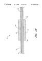
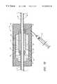
- FIGS. 1A-1Cillustrate an embodiment of an ultrasound assembly according to the present invention for use with a catheter according to the present invention.
- FIG. 1Ais a longitudinal cross sectional view of the ultrasound assembly 10 .
- FIG. 1Bis a lateral cross section of the ultrasound assembly 10 taken at the point labeled A in FIG. 1 A.
- FIG. 1Cis a lateral cross section of the ultrasound assembly 10 taken at the point labeled B in FIG. 1 A.
- the ultrasound assembly 10includes an elongated body 12 with an external surface 14 .
- a plurality of spacers 16are positioned over the external surface 14 of an elongated body 12 and a member 18 is positioned over at least a portion of the spacers 16 .
- the ultrasound assembly 10also includes an ultrasound transducer 20 with an external side 22 and an internal side 24 between a first end 26 and a second end 28 .
- the ultrasound transducer 20is positioned over the member 18 and can surround the member 18 .
- Suitable materials for the member 18include, but are not limited to, polyimide, polyester and nylon.
- a suitable ultrasound transducer 20includes, but is not limited to, PZT-4D, PZT-4, PZT-8 and various piezoceramics.
- the internal side 24 of the ultrasound transducer 20 , the spacers 16 and the member 18each define a portion of a chamber 30 between the internal side 24 of the ultrasound transducer 20 and the external surface 14 of the elongated body 12 .
- the chamber 30preferably has a height from 0.25-10 ⁇ m, more preferably from 0.50-5 ⁇ m and most preferably from 0.0-1.5 ⁇ m.
- the member 18can extend beyond the first end 26 and/or the second end 28 of the ultrasound transducer 20 . Additionally, the spacers 16 can be positioned beyond the ends of the ultrasound transducer 20 . As a result, the chamber 30 can extend along the longitudinal length of the ultrasound transducer 20 to increase the portion of the ultrasound transducer 20 which is adjacent to the chamber 30 .
- the chamber 30can contain a low acoustic impedance medium. Suitable low acoustic impedance media include, but are not limited to, fluids such as helium, argon, air and nitrogen and/or solids such as silicone and rubber.
- the chamber 30can also be evacuated. Suitable pressures for an evacuated chamber 30 include, but are not limited to, negative pressures to ⁇ 760 mm Hg.
- the internal side 24 of the ultrasound transducer 20can also be positioned adjacent to a chamber 30 .
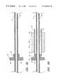
- the ultrasound assembly 10includes a collar 32 over external surface 14 of the elongated body 12 .
- the collar 32can surround the elongated body 12 .
- the collar 32has a spaced apart relationship to the ultrasound transducer 20 .
- a transducer sheath 34is positioned over at least a portion of the ultrasound transducer 20 and the collar 32 to form a chamber 30 adjacent to a side of the ultrasound transducer 20 .
- An inner side of the collar 32 , the ultrasound transducer 20 and the transducer sheath 34each partially define the chamber 30 .
- the chamber 30preferably has a width, W, from 12-2500 ⁇ m, more preferably from 25-250 ⁇ m and most preferably from 25-125 ⁇ m.
- the chamber 30can contain a low acoustic impedance medium. Suitable materials for the transducer sheath 34 include, but are not limited to air, N 2 , O 2 , and vacuum.
- the transducer sheath 34preferably has a thickness from 10-100 ⁇ m and more preferably from 25-50 ⁇ m.
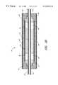
- the ultrasound assembly 10can also include a chamber 30 adjacent to the second end 28 of the ultrasound transducer 20 as illustrated in FIG. 1E.
- a second collar 36is positioned over the elongated body 12 and can surround the external surface 14 of the elongated body 12 .
- the second collar 36has a spaced apart relationship from the ultrasound transducer 20 so as to provide a second chamber 30 adjacent to the ultrasound transducer 20 .
- An inner side of the second collar 36 , the ultrasound transducer 20 and the transducer sheath 34each partially define the chamber 30 .
- the chamber 30preferably has a width, W, from 12-2500 ⁇ m, more preferably from 25-250 ⁇ m and most preferably from 25-125 ⁇ m.
- the chamber 30 adjacent to the second end 28 of the ultrasound transducer 20can also contain a low acoustic impedance medium.
- Each of the chamberscan be isolated from one another.
- one or more of the spacers 16can be formed of a porous material to provide communication between the chambers 30 . This communication can permit the pressures in each of the chambers 30 to reach an equilibrium.
- one or more of the spacers 16can include channels, lumens 38 and/or a ridged external surface to permit the communication between chambers 30 .
- An embodiment of the ultrasound assembly 10does not include a chamber 30 between the elongated body 12 and the internal side 24 of the ultrasound transducer 20 as illustrated in FIG. 1 F.
- the ultrasound transducer 20is positioned adjacent to the external surface 14 of the elongated body 12 such that a chamber 30 is not formed between the elongated body 12 and the ultrasound transducer 20 .
- the ultrasound assembly 10includes a collar 32 around the elongated body 12 in a spaced apart relationship from the ultrasound transducer 20 so as to form a chamber 30 adjacent to the first side of the ultrasound transducer 20 .
- the ultrasound assembly 10 of FIG. 1Fcan also include a second chamber 30 adjacent to the second end 28 of the ultrasound transducer 20 as illustrated in FIG. 1 G.
- the ultrasound assembly 10includes a second collar 36 over the elongated body 12 in a spaced apart relationship from the ultrasound transducer 20 . Accordingly a second chamber 30 is formed adjacent to the second side of the ultrasound transducer 20 .
- an embodiment of the ultrasound assembly 10does not include any chambers 30 .
- a utility lumen 38extends through the elongated body 12 .
- the utility lumen 38can be sized to receive a guidewire, to deliver therapeutic media including drugs, medication, microbubbles and other compounds which provide a therapeutic effect.
- the elongated body 12is illustrated as having a single utility lumen 38 , the elongated body 12 can include a plurality of lumens 38 or can be solid.
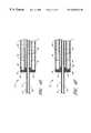
- Each of the ultrasound assemblies 10 illustrated in FIGS. 1A-1Hcan have a transducer sheath 34 which extends past the first collar 32 , the second collar 36 and/or past the ultrasound transducer 20 .
- FIGS. 2A-2Dillustrate such a transducer sheath 34 with a selection of the ultrasound assemblies 10 illustrated in FIGS. 1A-1H.
- the extension of the transducer sheath 34 past the collar 32 and/or past the ultrasound transducer 20provides a reservoir 40 at the ends of the ultrasound assembly 10 .
- the reservoir 40can optionally contain a binding medium 42 such as an epoxy or adhesive.
- the binding medium 42can serve to keep the ultrasound transducer 20 intact during the handling of the ultrasound assembly 10 .
- transducer sheath 34illustrates the transducer sheath 34 extending past the first collar 32 , the second collar 36 and/or the ultrasound transducer 20 at both ends of the ultrasound assembly 10 , the transducer sheath 34 can extending past a collar 32 and/or ultrasound transducer 20 at only one end of the ultrasound assembly 10 .
- FIGS. 3A-3Dillustrate a selection of the above ultrasound assemblies 10 including an assembly sheath 44 positioned over the ultrasound transducer 20 .
- Suitable materials for the assembly sheath 44include, but are not limited to polyimide, PTFE, and polyurethane.
- the assembly sheath 44preferably has a thickness from 12-75 ⁇ m and more preferably from 25-50 ⁇ m.
- a volume between the assembly sheath 44 and the ultrasound transducer 20can contain a binding medium 42 as illustrated in FIG. 3 A. Further, when the ultrasound assembly 10 includes a transducer sheath 34 , the volume between the ultrasound assembly 10 sheath and the transducer sheath 34 can contain the binding medium 42 as illustrated in FIGS. 3B-3D.
- the binding medium 42can be a binding medium 42 which serves to keep the ultrasound transducer 20 intact during the handling of the ultrasound assembly 10 .
- Each of the ultrasound assemblies 10 illustrated aboveshow the elongated body 12 extending outward from the ultrasound assembly 10 .
- the elongated body 12can be trimmed to provide an elongated body 12 which is flush with one or more sides of the elongated body 12 .
- a sensorsuch as a temperature sensor can be positioned in the binding medium 42 associated with any of the above ultrasound assemblies 10 .
- FIGS. 4A-4Fillustrate various arrangements between the collars 32 and spacers 16 for use with the ultrasound assemblies 10 discussed above.
- FIG. 4Aillustrates the collar 32 abutting the spacers 16 .
- the collar 32can be spaced apart from the spacers 16 as illustrated in FIG. 4 B.
- the collar 32is sized to be positioned around the spacer 16 as illustrated in FIG. 4 C.
- the collar 32is sized to be positioned around the member 18 as illustrated in FIG. 4 D.
- the collar 32can be integral with the spacers 16 as illustrated in FIG. 4 E.
- the spacer 16has an L-shaped profile with a spacer region 46 positioned adjacent to the member 18 and a collar region 48 positioned adjacent to the transducer sheath 34 . Accordingly, the raised edge serves to define a side of the chamber 30 .
- the spacer 16can include a seat 50 sized to receive an edge of the member 18 as illustrated in FIG. 4 F.
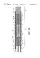
- FIGS. 5A and 5Billustrate a catheter according to the present invention.
- the cathetercan include any of the ultrasound assemblies 10 discussed or suggested above.
- the catheteris illustrated with a generalized representation of an ultrasound assembly 10 .
- an ultrasound assembly 10is illustrated as an ultrasound transducer 20 over an elongated body 12 .
- a box 51 over the ultrasound transducer 20represents the remaining portions of each ultrasound assembly 10 .
- the box 51can represent the collars 32 , spacers, members, chambers, binding media, etc. associated with an ultrasound assembly 10 .
- the catheterincludes a catheter body 52 having an external surface 53 , a distal portion 54 and a proximal portion 56 .
- the catheter body 52can include an extension region 58 , an assembly region 60 and a terminal region 62 .
- Lumens 38 within the extension region 58 , assembly region 60 and terminal region 62are aligned with one another to provide one or more lumens 38 extending through the entire catheter. These lumens 38 can be sized to receive a guidewire or for the delivery of a therapeutic agent such as a drug.
- the extension region 58includes an extension body 64 having one or more lumens 38 .
- the one or more lumens 38 included in the extension body 64have cross sectional dimensions approximating the cross section dimensions of the one or more utility lumens 38 of the elongated body 12 .
- the extension body 64can be used to add length to the catheter. Specifically, the extension body 64 can provide additional length beyond the length provided by the assembly region 60 . Accordingly, the extension body 64 can be short or can be eliminated from the catheter body 52 .
- Suitable materials for the extension body 64include, but are not limited to, polyimide, silicone, and polyurethane.
- the terminal region 62is positioned at the distal tip of the catheter.
- the terminal region 62includes a terminal body 66 .
- the terminal body 66can be solid or include one or more lumens 38 with cross sectional dimensions approximating the cross section dimensions of the one or more utility lumens 38 of the elongated body 12 .
- Suitable materials for the terminal region 62include, but are not limited to, polyimide, silicone, and polyurethane.
- the assembly region 60is the region of the catheter body 52 including any of the ultrasound assemblies 10 discussed and/or suggested above.
- a catheter sheath 68is positioned over the extension region 58 , the assembly region 60 and the terminal region 62 so as to define a portion of the external surface 53 of the catheter body 52 .
- the catheter sheath 68can serve to immobilize the extension region 58 , the assembly region 60 and the terminal region 62 relative to one another.
- the catheter sheath 68is optional and can be removed from the catheter body 52 .
- the volume between the ultrasound assembly 10 and the extension body 64can contain a binding medium 42 .
- binding mediacan serve to couple the extension region 58 , the assembly region 60 and the terminal region 62 together.
- Suitable materials for the catheter sheath 68include, but are not limited to polyethelyne, polyurethane, and polyimide.
- the thickness of the catheter sheath 68 materialis preferably 0.001′′ to 0.020′′, more preferably 0.004′′ to 0.010′′ and most preferably 0.006′′ to 0.008′′.
- a first binding medium 42 Acan be positioned adjacent to the ends of the ultrasound transducer 20 .
- a volume between the extension body 64 and the ultrasound transducer 20can contain the first binding medium 42 A.
- the volume between the terminal body 66 and the ultrasound transducer 20can contain the first binding medium 42 A.
- the first binding medium 42 Acan also be positioned adjacent to the external side 22 of the ultrasound transducer 20 as illustrated in FIG. 5 C. Specifically, the first binding medium 42 A can be contained in a volume between the external side 22 of the ultrasound transducer 20 and the externals surface of the catheter body 52 .
- a cathetercan include a first binding medium 42 A and a second binding medium 42 B.
- the first binding medium 42 Ais adjacent to the ends of the ultrasound transducer 20 and the second binding medium 42 B is adjacent to the external side 22 of the ultrasound transducer 20 .
- the second binding medium 42 Bcan be contained in a volume between the external side 22 of the ultrasound transducer 20 and the external surface 53 of the catheter body 52 .
- a portion of the second binding medium 42 Bis also illustrated as being adjacent to the ends of the ultrasound assembly 10 although the second binding medium 42 B can be restricted to the volume adjacent to the external side 22 of the ultrasound transducer 20 .
- the first binding medium 42 A and the second binding medium 42 Bcan be the same or different.
- the second binding medium 42 Bis preferably harder than the first binding medium 42 A.
- a harder binding medium 42typically transmits ultrasound energy more efficiently than a softer binding medium 42 .
- the hardness of the second binding medium 42 Bcan preserve the ultrasound transmitting efficiency of the catheter.
- the softness of the first binding medium 42 Aprovides the catheter with additional flexibility. As a result, the choices of the first and second binding media effect both the flexibility and the ultrasound transmission efficiency of the catheter.
- the second binding medium 42 Bis preferably at least 2 times harder than the first binding medium 42 A and more preferably from about 3 to about 5 times harder than the first binding medium 42 A.
- the first binding medium 42 Apreferably has a hardness of at least about 10 Shore D, more preferably from about 15 to about 80 Shore D and most preferably from about 20 to about 40 Shore D.
- the second binding medium 42 Bpreferably has a hardness of at least about 60 Shore D, more preferably from about 65 to about 120 Shore D and most preferably from about 80 to about 100 Shore D.
- FIG. 5Eillustrates a particular example of a catheter including an assembly sheath 44 over the ultrasound transducer 20 .
- FIG. 5Billustrates the catheter including the ultrasound assembly 10 of FIG. 2 B .
- the ultrasound assembly 10includes a chamber 30 adjacent to a first end 26 of the ultrasound transducer 20 .
- the chamber 30is positioned proximally relative to the ultrasound transducer 20 .
- the ultrasound assembly 10includes another chamber 30 between the ultrasound transducer 20 and the external surface 14 of the elongated body 12 .
- Each chamber 30contains a low acoustic impedance medium. As a result, this embodiment of the catheter efficiently transmits ultrasound energy in the distal direction.
- the catheter of FIG. 5Eincludes a first binding medium 42 A, a second binding medium 42 B and a third binding medium 42 C.
- the first binding medium 42 Ais adjacent to the ends of the ultrasound transducer 20 and the second binding medium 42 B is contained in a volume between the assembly sheath 44 and the external surface 53 of the catheter body 52 .
- the third binding medium 42 Cis adjacent to the external side 22 of the ultrasound transducer 20 .
- a volume between the ultrasound transducer 20 and the assembly sheath 44includes the third binding medium 42 C.
- first, second and third binding mediacan be the same or they can all be different.
- the first and second binding mediaare the same while the third binding medium 42 C is harder than the first and second binding media.
- the third binding mediais preferably harder than the first binding medium 42 A.
- the first binding medium 42 Ais also more flexible than the third binding medium 42 C.
- the third binding medium 42 Cis preferably at least 2 times harder than the first binding medium 42 A and more preferably from about 3 to about 5 times harder than the first binding medium 42 A.
- the first binding medium 42 Cpreferably has a hardness of at least about 10 Shore D, more preferably from about 15 to about 80 Shore D and most preferably from about 20 to about 40 Shore D.
- the third binding medium 42 Bpreferably has a hardness of at least about 60 Shore D, more preferably from about 65 to about 120 Shore D and most preferably from about 80 to about 100 Shore D.
- the second and third binding mediaare each harder than the first binding medium 42 A.
- the second and third binding mediaare the same and are harder than the first binding medium 42 A.
- FIG. 5Fillustrates a particular example of a catheter having a transducer sheath 34 extending beyond the collar 32 and the ultrasound transducer 20 to form reservoirs 40 at the end of the ultrasound assembly 10 .
- the catheterincludes a first binding medium 42 A, a second binding medium 42 B and a third binding medium 42 C.
- the first binding medium 42 Ais adjacent to the ends of the ultrasound transducer 20 and the second binding medium 42 B is adjacent to the external side 22 of the ultrasound transducer 20 .
- Reservoirs 40 formed adjacent to the ends of the ultrasound transducer 20contain the third binding medium 42 C.
- the first, second and third binding mediacan be the same or they can all be different.
- the second binding medium 42 Bpreferably transmits ultrasound energy more efficiently than the first binding medium 42 A.
- the first binding medium 42 Ais preferably more flexible than the second binding medium 42 B.
- the first and second binding mediapreferably have the hardness relationships and levels described with respect to the first and second binding media of FIG. 5 D. In a preferred embodiment, the first and third binding media are the same.
- the cathetercan include two or more ultrasound assemblies 10 as illustrated in FIGS. 6A and 6B.
- FIG. 6Aillustrates the ultrasound assembly 10 in contact with the catheter sheath 68 while
- FIG. 6Billustrates the ultrasound assemblies 10 spaced apart from the catheter sheath 68 .
- the ultrasound assemblies 10can share the same elongated body 12 and/or different ultrasound assemblies 10 can include different elongated bodies 12 .
- the ultrasound assemblies 10are formed with different elongated bodies 12 , the different elongated bodies 12 can be aligned with one another during assembly of the catheter.
- Two or more ultrasound assemblies 10can share a member 18 as illustrated in FIG. 6 C. Each of the ultrasound assemblies 10 is positioned over the same member 18 . As a result, the member 18 partially defines a chamber 30 between each of the ultrasound transducers 20 and the elongated body 12 . When different ultrasound transducers 20 share a member 18 , spacers 16 can be optionally positioned between the ultrasound assemblies 10 . As a result, a single member 18 can be positioned over at least a portion of three or more spacers 16 .
- a first binding medium 42 Acan be positioned adjacent to the ends of the ultrasound transducers 20 .
- the first binding medium 42 Acan be contained in a volume between an ultrasound transducer 20 and an extension body 64 , a volume between adjacent ultrasound transducer 20 , and/or a volume between an ultrasound transducer 20 and a terminal body 66 .
- a catheter including a plurality of ultrasound assemblies 10can also include a second binding medium 42 B adjacent to the external side 22 of the ultrasound transducers 20 .
- the second binding medium 42 Bcan be contained in a volume between the external side 22 of the ultrasound transducer 20 and the external surface 53 of the catheter body 52 .
- the first and second binding mediacan be the same or different and the second binding medium 42 B is preferably harder than the first binding medium 42 A.
- the inclusion of specific ultrasound assembly 10 embodimentscan result in the catheter including additional binding media.
- that binding mediais preferably at least as hard as the first and second binding media.
- FIGS. 7A-7Eillustrate a method for fabricating ultrasound assemblies 10 according to the present invention.
- spacers 16are positioned over an elongated body 12 .
- the spacers 16can optionally be adhesively attached to the elongated body 12 with compounds such as epoxy.
- FIG. 7Billustrates a member 18 positioned over the spacers 16 .
- the positioning of the member 18forms a chamber 30 between the member 18 and the elongated body 12 .
- the member 18can optionally be adhesively attached to the spacers 16 with compounds such as epoxy.
- FIG. 7Can ultrasound transducer 20 is positioned over the member 18 to form the ultrasound assembly 10 of FIG. 1 A.
- the ultrasound transducer 20can optionally be adhesively attached to the member 18 with compounds such as epoxy.
- a collar 32is also positioned over the elongated body 12 and can be attached to the elongated body 12 with compounds such as epoxy.
- FIG. 7Dillustrates a transducer sheath 34 positioned over the collar 32 to form the ultrasound assembly 10 of FIG. 2 B.
- the transducer sheath 34forms a chamber 30 adjacent to the ultrasound transducer 20 .
- an assembly sheath 44is positioned over the transducer sheath 34 of the ultrasound assembly 10 illustrated in FIG. 7D.
- a binding medium 42 precursoris delivered adjacent to the external side 22 of the ultrasound transducer 20 .
- the binding medium 42 precursoris delivered into a volume between the transducer sheath 34 and the assembly sheath 44 .
- the binding medium 42can be delivered into the volume using an injection device such as a hypodermic needle 70 .
- the binding medium 42can solidify to provide the ultrasound assembly 10 of FIG. 3 B. Suitable mechanisms for solidification include, but are not limited to, setting, cooling and curing.
- FIGS. 8A-8Dillustrate method for forming ultrasound assemblies 10 when the collar 32 is integral with the spacers 16 .
- FIG. 8Aillustrates a spacer 16 positioned over an elongated body 12 .
- a member 18is positioned over the spacer 16 and an ultrasound transducer 20 is positioned over the member 18 .
- FIG. 8Ca second spacer 16 is positioned over the elongated body 12 and moved toward the original spacer 16 until a portion of the spacer 16 is positioned between the member 18 and the elongated body 12 .
- a chamber 30is formed between the member 18 and the elongated body 12 .
- a transducer sheath 34is positioned over the spacers 16 and the ultrasound transducer 20 to form the ultrasound assembly 10 of FIG. 3C having collars 32 which are integral with the spacers 16 .
- FIGS. 9A-9Billustrate an adaptation of the method illustrated in FIGS. 7A-7E to form an ultrasound assembly 10 having a transducer sheath 34 which extends past a first collar 32 , a second collar 36 and/or past the ultrasound transducer 20 as discussed with respect to FIGS. 2A-2D.
- FIG. 9Aillustrates a transducer sheath 34 positioned over the collar 32 and ultrasound transducer 20 of FIG. 7 C.
- the ultrasound transducer 20extends past the collar 32 and the ultrasound transducer 20 to form reservoirs 40 adjacent to the ends of the ultrasound transducer 20 .
- FIG. 9Billustrates a binding medium 42 precursor being delivered into the reservoirs 40 to provide the ultrasound assembly 10 illustrated in FIG. 2 B.
- FIGS. 7A-9Bcan be used to provide an elongated body 12 having a plurality of ultrasound assemblies 10 .
- Each ultrasound assembly 10can be concurrently formed on the elongated body 12 or they can be sequentially formed on the elongated body 12 .
- a portion of each ultrasound assembly 10can be formed concurrently while the remaining portions of the ultrasound assemblies 10 are formed sequentially.
- the chamber 30 between each ultrasound transducer 20 and the external surface 14 of the elongated body 12can be formed concurrently while the remaining portions of the ultrasound assemblies 10 are formed sequentially.
- FIGS. 10A-10Dillustrate methods for forming a catheter according to the present invention.
- FIG. 10Aillustrates a catheter sheath 68 positioned over an extension body 64 as illustrated by the arrow labeled A.
- the ultrasound assembly 10is then positioned within the catheter sheath 68 as illustrated by the arrow labeled B.
- a terminal body 66is then positioned within the catheter sheath 68 as indicated by the arrow labeled C.
- a binding medium 42 precursoris delivered adjacent to an end of the ultrasound transducer 20 .
- the binding medium 42 precursoris delivered into a volume between the ultrasound assembly 10 and the terminal body 66 .
- FIG. 10Billustrates the binding medium 42 precursor delivered adjacent to an end of the ultrasound assembly 10 using an injection instrument such as a hypodermic needle 70 .
- the binding medium 42 precursorcan be sequentially delivered adjacent to one end of the ultrasound transducer 20 and then adjacent to the opposing end of the ultrasound transducer 20 .
- the binding medium 42 precursorpreferably solidifies to form a binding media adjacent to the ends of the ultrasound transducer 20 .
- a binding medium 42 precursorcan also be delivered into a volume between the external side 22 of the ultrasound transducer 20 and the external surface 53 of the catheter body 52 .
- the quantity of binding medium 42 precursor deliveredcan be enough to fill the volume adjacent to the external side 22 of the ultrasound transducer 20 .
- the binding medium 42 precursorpreferably solidifies to form a binding medium 42 adjacent to the external side 22 of the ultrasound transducer 20 .
- sufficient binding medium 42 precursorcan be delivered to fill the volume adjacent to the ends of the ultrasound transducer 20 .
- a second binding medium 42 B precursorcan be delivered into the volumes adjacent to the ends of the ultrasound transducer 20 as illustrated in FIG. 10 D.
- the second binding medium 42 B precursorpreferably solidifies to form a second binding medium 42 B adjacent to the ends of the ultrasound transducer 20 .
- a fluid low acoustic impedance mediumcan be delivered into the chamber 30 .
- a low acoustic impedance mediumpreferably has an acoustic impedance less than about 1.7 Megarayls, more preferably of about 0-0.7 Megarayls and most preferably from 0-0.4 Megarayls.
- suitable low acoustic impedance mediainclude, but are not limited to, helium, argon, air and nitrogen. These media can be delivered into the chamber 30 during or after the media solidification process using an injection device such as a hypodermic needle 70 . Similar techniques can be used to draw a vacuum within the chamber 30 .
- Solid low acoustic impedance mediasuch as silicones and rubbers can be positioned within the chamber 30 during the formation of the ultrasound assembly 10 .
- the methods for forming a catheter described with respect to FIGS. 10A-10Dcan be used to form a catheter having multiple ultrasound assemblies 10 .
- the elongated body 12 illustrated in FIG. 10Acan be replaced with an elongated body 12 having a plurality of ultrasound assemblies 10 .
- several independent elongated bodies 12 having ultrasound assemblies 10can be sequentially positioned within the catheter sheath 68 .
- the one or more lumens 38 in adjacent elongated bodies 12are aligned before binding medium 42 precursor is delivered into the volume defined by the catheter sheath 68 .
- Additional catheters having a plurality of ultrasound transducersare described in U.S. patent application Ser. No. 09/071,285, filed May 1, 1998 and entitled Ultrasound Catheter for Providing a Therapeutic Effect to a Vessel of a Body which is incorporated herein in its entirety.
- the methods for forming the ultrasound assembly 10 or cathetercan include matching the resonant frequencies of the ultrasound transducers 20 .
- the ultrasound transducers 20can be selected such that any member of the plurality of ultrasound transducers 20 has a resonant frequency within about 10% of the resonant frequency of any other ultrasound transducer 20 . More preferably, the ultrasound transducers 20 are selected such that any one has a resonant frequency within about 3%, even more preferably within about 1% and most preferably within about 0.5% of any other ultrasound transducer 20 in the plurality of ultrasound transducers 20 . The selected ultrasound transducers 20 are then used to form an ultrasound assembly 10 or catheter.
- the matching of the ultrasound transducers 20allows the ultrasound transducers to be concurrently driven at a single frequency while reducing the inefficiencies associated with driving ultrasound transducers 20 at a frequency which is significantly different than their resonant frequency. Since the ultrasound transducers 20 can be driven at a single frequency, the matching the resonant frequencies of the ultrasound transducers 20 is preferred when the plurality of ultrasound transducers 20 are connected in parallel or in series.
- the electrical connections for driving the one or more ultrasound to transducers 20can be done at various stages during the assembly of the catheter and/or ultrasound assembly 10 .
- electrical wirescan be coupled with the ultrasound transducers 20 before the ultrasound transducers 20 are positioned over the elongated body.
- the electrical wirescan be coupled with the ultrasound transducers 20 after the ultrasound transducers 20 are in position over the elongated body.
- electrical connectionscan be made alternating with positioning the ultrasound transducers 20 over the elongated body.
- one or more electrical wirescan be positioned along the elongated body before the ultrasound transducers 20 are positioned over the elongated body.
- One or more ultrasound transducers 20can then be slid over the elongated body such that the one or more electrical wires contact the inner side of the ultrasound transducers 20 .
- the contact between the ultrasound transducers 20 and the electrical wirecan serve as the electrical connection to the one or more ultrasound transducers 20 .
- the ultrasound transducers 20can be connected in parallel, in series or independently connected. Wires extending from the one or more ultrasound transducers 20 can be threaded up through one or more lumens 38 in the extension body 64 .
- one or more sensorscan be included in any of the media described above.
- the sensorcan be positioned within a volume before a medium is delivered into the volume.
- the sensorcan be delivered into a binding medium 42 precursor while the binding medium 42 precursor is in a flowable state.
- Wires extending from the one or more sensorscan be threaded up through one or more lumens 38 in the extension body 64 .
- Suitable sensors for use with the catheterinclude, but are not limited to, a temperature sensor.
- the temperature sensoris preferably positioned adjacent to the external side 22 of an ultrasound transducer 20 .
- the one or more temperature sensorsare preferably positioned in a volume between the external side 22 of the ultrasound transducer 20 and the external surface 53 of the catheter body 52 .
- the solidification of the binding medium 42 precursorscan occur concurrently or independently of one another. As discussed with respect to FIGS. 5A-5F, the binding medium 42 precursor and the second binding medium 42 B precursor preferably solidify to different degrees of hardness.
- Binding medium 42 precursors for use with the catheters and ultrasound assemblies 10 discussed aboveare preferably flowable to optimize delivery into a desired volume. These precursors preferably solidify to a binding medium 42 having a reduced flowability. These precursors more preferably solidify to a binding medium 42 having a reduced flowability and an increased degree of adhesiveness. This solidification can occur through mechanisms including, but not limited to, cooling, setting and curing.
- Suitable binding media precursors and/or binding mediainclude, but are not limited to, adhesives, epoxies, polymers, plastics, rubbers. Examples of suitable binding media with different degrees of hardness are EPOTEK 310 having a hardness of about 22 Shore D and HYSOL 3561 and 2939 having a hardness of about 85 Shore D.
- the binding media to be usedcan be selected for its particular hardness. Alternatively, binding media, such as epoxies, cure to a different hardness based on the component ratio in the binding media. The component ratio can be adjusted to achieve the desired hardness.
- the binding media adjacent to the external side 22 of the ultrasound transducer 20 and/or adjacent to the ends of the ultrasound transducer 20preferably has an acoustic impedance of about 1-20 Megarayls, more preferably about 1.3-10 Megarayls and most preferably about 4-8 Megarayls.
- the low acoustic impedance medium contained within the chamberspreferably has an acoustic impedance less than about 1.7 Megarayls, more preferably of about 0-0.7 Megarayls and most preferably from 0-0.4 Megarayls.
- the ratio of the acoustic impedances for the binding medium adjacent to the external side and/or adjacent ends the of the ultrasound transducer 20 measured relative to the acoustic impedance of the low acoustic impedance medium contained within the chambersis preferably at least 1.5:1, more preferably at least 2:1 and most preferably at least 4:1. Additionally the ratio is preferably 1.5:1 to 10,000:1, more preferably about 1.5:1 to 100:1 and most preferably 1.5:1 to, 4:1.
- FIG. 11illustrates the proximal portion 72 of a catheter according to the present invention.
- An electrical coupling 74extends from the proximal portion 72 of the catheter.
- the electrical coupling 74can be coupled with a catheter control system (not shown) for adjusting the frequency and power of ultrasound energy delivered from the catheter. These adjustments can be made in response to signals from one or more sensors included with the catheter. For instance, these adjustments can be made in response to signals form a temperature sensor in order to maintain the temperature at a treatment site within a particular range.
- the electrical coupling 74includes an autotransformer 76 for adjusting the characteristic impedance of the catheter to match the impedance of an amplifier included in the catheter control system. For instance, if the amplifier has an input impedance of 50 ohms and the catheter has a characteristic impedance of 40 ohms, the addition of the autotransformer can provide the catheter with a characteristic impedance of about 50 ohms. The matched impedance serves to increase the efficiency of the catheter system.
- a method of assembling a cathetercan include the step of providing an autotransformer which matches the characteristic impedance of the catheter to the characteristic impedance of a component in a catheter control system.
- the electrical couplingalso includes catheter identification electronics 78 .
- the catheter identification electronics 78indicate to the catheter control system what frequency the catheter should be driven.
- the catheter identification electronics 78can be one or more resistors.
- the catheter control systemcan include logic for identifying the resistance. This resistance can be associated with a catheter of a particular frequency. The logic can identify the particular frequency of the catheter and can then cause the catheter to be driven at the indicated frequency.
- a computer chipis another example of suitable catheter identification electronics 78 . The computer chip can produce signals indicating the frequency of the catheter to the catheter control system. In response, the catheter control system can drive the catheter at the appropriate frequency.
- FIGS. 12A-12Dillustrate a sheath 82 configured to receive the catheter.
- the sheath 82includes a sheath proximal end 84 and a sheath distal end 86 .
- a catheter receiving lumen 88extends through the sheath 82 and is sized to receive the catheter as illustrated in FIG. 12 B.
- the sheath distal end 86preferably includes an energy delivery portion which is constructed from a material which efficiently transmits ultrasound energy. Suitable materials for both the sheath 82 and the energy delivery section 90 include, but are not limited to, polyethylene.
- the cathetercan be rotated or moved within the sheath 82 as illustrated by the arrow labeled A.
- the movement of the catheter within the sheath 82can be caused by manipulating the proximal portion of the catheter body 52 while holding the sheath proximal end 84 stationary.
- the sheath distal end 86can include on or more temperature sensors.
- the sheath 82can also optionally include a drug delivery lumen 92 .
- the drug delivery lumen 92can include one or more drug delivery ports 94 through which a drug can be delivered.
- the drug delivery lumen 92can be straight but is preferably curved and more preferably spirals around the catheter receiving lumen 88 as illustrated in FIGS. 12C and 12D.
- the drug delivery lumen 92preferably has a diameter/width of about 0.0005′′-0.005′′ and more preferably about 0.001′′-0.003′′.
- the drug delivery ports 94are positioned close enough to achieve a substantially even flow of drug solution around the circumference of the sheath 82 .
- the proximity of adjacent drug delivery ports 94can be changed by changing the density of drug delivery ports 94 along the drug delivery lumen 92 or by changing the number of windings of the drug delivery lumen 92 around the energy delivery section 90 .
- Suitable displacement between adjacent drug delivery ports 94includes, but is not limited to, from 0.1′′ to 1.0′′, preferable 0.2′′ to 0.6′′.
- the size of the drug delivery ports 94can be the same or change along the length of the drug delivery lumen 92 .
- the size of the drug delivery ports 94 distally positioned on the drug delivery sectioncan be larger than the size of the drug delivery ports 94 which are proximally positioned on the drug delivery section.
- the increase in sizes of the drug delivery ports 94can be designed to produce similar flowrates of drug solution through each drug delivery port 94 . This similar flowrate increases the uniformity of drug solution flowrate along the length of the sheath 82 .
- a suitable size for a drug delivery portincludes, but is not limited to 0.0005′′ to 0.0050′′.
- suitable sizes for proximally positioned drug delivery ports 94includes, but is not limited to from 0.0001′′ to 0.005′′ and suitable sizes for distally positioned drug delivery ports 94 includes, but is not limited to, 0.0005′′ to 0.0020′′.
- the increase in size between adjacent drug delivery ports 94can be substantially uniform between or along the drug delivery lumen 92 .
- the dimensional increase of the drug delivery ports 94is dependent upon material and diameter of the drug delivery lumen 92 .
- the drug delivery ports 94can be formed by burnt into the sheath 82 with a laser.
- Uniformity of the drug solution flow along the length of the sheath 82can also be increased by increasing the density of the drug delivery ports 94 toward the distal end of the drug delivery lumen 92 .
- the drug delivery ports 94can optionally be closed slits in the sheath 82 .
- the slitscan have a straight or arcuate shape.
- the slitsremain closed until the pressure within the drug delivery lumen 92 exceeds a threshold pressure.
- the pressure within the drug delivery lumen 92builds, the pressure on each of the slits will be approximately uniform. Once, the threshold pressure is reached, the uniform pressure will result in the slits opening almost simultaneously and cause a nearly uniform flow of drug solution out of all the slits.
- the slitsclose and prevent delivery of additional drug solution.
- the slit shapecan also prevent the drug delivery ports 94 from opening when exposed to low pressures from outside the sheath 82 . As a result, slit shaped drug delivery ports 94 can maximize control of drug delivery.
- FIGS. 13A-13Gillustrate a method for using the catheter with a sheath 82 .
- a guidewireis directed through vessels toward a treatment site which includes a clot.
- the guidewireis directed through the clot.
- Suitable vesselsinclude, but are not limited to, cardiovascular vessels, the pancreas, sinuses, esophagus, rectum, gastrointestinal vessels and urological vessels.
- the catheter receiving lumen 88 of the sheath 82is slid over the guidewire and the sheath 82 is advanced along the guidewire using traditional over-the-guidewire techniques.
- the sheath 82is advanced until the sheath distal end 86 is positioned at the clot.
- Radio opaque markersmay be positioned at the sheath distal end 86 to aid in the positioning of the sheath 82 within the treatment site .
- a drug solution sourceis coupled with the drug inlet port.
- the drug solution sourcecan be a syringe with a Luer fitting which is complementary with the drug inlet port. Pressure can be applied to a plunger on the drug solution source to drive the drug solution through the drug delivery lumen 92 .
- the drug solutionis delivered from the drug delivery lumen 92 through the drug delivery ports 94 as illustrated by the arrows in FIG. 13 E.
- Suitable drug solutionsinclude, but are not limited to, an aqueous solution containing Heparin, Uronkinase, Streptokinase, or tissue Plasminogen Activator (TPA).
- the catheteris inserted into the catheter receiving lumen 88 until the ultrasound assembly 10 is positioned at the sheath distal end 86 .
- radiopaque markersmay be positioned on the catheter adjacent to each of the ultrasound transducers 20 .
- the ultrasound transducers 20themselves can be radiopaque.
- the ultrasound transducer 20can be moved within the energy delivery section 90 as illustrated by the arrows labeled A.
- the movement of the ultrasound transducer 20 within the energy delivery section 90can be caused by manipulating the body proximal section while holding the sheath proximal end 84 stationary.
Landscapes
- Health & Medical Sciences (AREA)
- Engineering & Computer Science (AREA)
- Life Sciences & Earth Sciences (AREA)
- Animal Behavior & Ethology (AREA)
- Veterinary Medicine (AREA)
- Public Health (AREA)
- General Health & Medical Sciences (AREA)
- Surgery (AREA)
- Mechanical Engineering (AREA)
- Biomedical Technology (AREA)
- Heart & Thoracic Surgery (AREA)
- Medical Informatics (AREA)
- Acoustics & Sound (AREA)
- Physics & Mathematics (AREA)
- Multimedia (AREA)
- Dermatology (AREA)
- Biophysics (AREA)
- Orthopedic Medicine & Surgery (AREA)
- Vascular Medicine (AREA)
- Nuclear Medicine, Radiotherapy & Molecular Imaging (AREA)
- Hematology (AREA)
- Molecular Biology (AREA)
- Anesthesiology (AREA)
- Chemical & Material Sciences (AREA)
- Pulmonology (AREA)
- Medicinal Chemistry (AREA)
- Pharmacology & Pharmacy (AREA)
- Epidemiology (AREA)
- Surgical Instruments (AREA)
- Ultra Sonic Daignosis Equipment (AREA)
- Media Introduction/Drainage Providing Device (AREA)
Abstract
Description
Claims (13)
Priority Applications (5)
| Application Number | Priority Date | Filing Date | Title |
|---|---|---|---|
| US09/374,642US6676626B1 (en) | 1998-05-01 | 1999-08-16 | Ultrasound assembly with increased efficacy |
| PCT/US2000/021302WO2001013357A1 (en) | 1999-08-16 | 2000-08-04 | Ultrasound assembly for use with a catheter |
| JP2001517374AJP2003507105A (en) | 1999-08-16 | 2000-08-04 | Ultrasound assembly for use with a catheter |
| EP00952498AEP1206771A1 (en) | 1999-08-16 | 2000-08-04 | Ultrasound assembly for use with a catheter |
| US10/735,588US7976483B2 (en) | 1997-05-01 | 2003-12-12 | Ultrasound assembly with increased efficacy |
Applications Claiming Priority (5)
| Application Number | Priority Date | Filing Date | Title |
|---|---|---|---|
| US09/071,285US6001069A (en) | 1997-05-01 | 1998-05-01 | Ultrasound catheter for providing a therapeutic effect to a vessel of a body |
| US09/107,078US6723063B1 (en) | 1998-06-29 | 1998-06-29 | Sheath for use with an ultrasound element |
| US09/129,980US6210356B1 (en) | 1998-08-05 | 1998-08-05 | Ultrasound assembly for use with a catheter |
| US09/375,162US6582392B1 (en) | 1998-05-01 | 1999-08-16 | Ultrasound assembly for use with a catheter |
| US09/374,642US6676626B1 (en) | 1998-05-01 | 1999-08-16 | Ultrasound assembly with increased efficacy |
Related Parent Applications (4)
| Application Number | Title | Priority Date | Filing Date |
|---|---|---|---|
| US09/071,285Continuation-In-PartUS6001069A (en) | 1997-05-01 | 1998-05-01 | Ultrasound catheter for providing a therapeutic effect to a vessel of a body |
| US09/107,078Continuation-In-PartUS6723063B1 (en) | 1997-05-01 | 1998-06-29 | Sheath for use with an ultrasound element |
| US09/129,980Continuation-In-PartUS6210356B1 (en) | 1995-03-05 | 1998-08-05 | Ultrasound assembly for use with a catheter |
| US09/375,162Continuation-In-PartUS6582392B1 (en) | 1997-05-01 | 1999-08-16 | Ultrasound assembly for use with a catheter |
Related Child Applications (1)
| Application Number | Title | Priority Date | Filing Date |
|---|---|---|---|
| US10/735,588ContinuationUS7976483B2 (en) | 1997-05-01 | 2003-12-12 | Ultrasound assembly with increased efficacy |
Publications (1)
| Publication Number | Publication Date |
|---|---|
| US6676626B1true US6676626B1 (en) | 2004-01-13 |
Family
ID=29783315
Family Applications (2)
| Application Number | Title | Priority Date | Filing Date |
|---|---|---|---|
| US09/374,642Expired - LifetimeUS6676626B1 (en) | 1997-05-01 | 1999-08-16 | Ultrasound assembly with increased efficacy |
| US10/735,588Expired - Fee RelatedUS7976483B2 (en) | 1997-05-01 | 2003-12-12 | Ultrasound assembly with increased efficacy |
Family Applications After (1)
| Application Number | Title | Priority Date | Filing Date |
|---|---|---|---|
| US10/735,588Expired - Fee RelatedUS7976483B2 (en) | 1997-05-01 | 2003-12-12 | Ultrasound assembly with increased efficacy |
Country Status (1)
| Country | Link |
|---|---|
| US (2) | US6676626B1 (en) |
Cited By (26)
| Publication number | Priority date | Publication date | Assignee | Title |
|---|---|---|---|---|
| US20030167023A1 (en)* | 1997-05-01 | 2003-09-04 | Frederick J. Bennett | Ultrasound catheter for providing a therapeutic effect to a vessel of a body |
| US20030199794A1 (en)* | 2002-04-17 | 2003-10-23 | Olympus Optical Co., Ltd. | Ultrasonic operating apparatus |
| US20040049148A1 (en)* | 2001-12-03 | 2004-03-11 | Oscar Rodriguez | Small vessel ultrasound catheter |
| US20040199228A1 (en)* | 2003-01-03 | 2004-10-07 | Wilson Richard R. | Ultrasonic catheter with axial energy field |
| US20050010112A1 (en)* | 1997-05-01 | 2005-01-13 | Bennett Frederick J. | Ultrasound assembly with increased efficacy |
| US20050197619A1 (en)* | 2003-04-22 | 2005-09-08 | Rule Peter R. | Ultrasound enhanced central venous catheter |
| US20060058708A1 (en)* | 2003-12-24 | 2006-03-16 | Gill Heart | Method and apparatus for ultrasonically increasing the transportation of therapeutic substances through tissue |
| US20060206039A1 (en)* | 2002-02-28 | 2006-09-14 | Wilson Richard R | Ultrasound catheter with embedded conductors |
| US20080103417A1 (en)* | 2006-10-27 | 2008-05-01 | Azita Soltani | Catheter with multiple ultrasound radiating members |
| US20080171965A1 (en)* | 2007-01-08 | 2008-07-17 | Ekos Corporation | Power parameters for ultrasonic catheter |
| US20080274097A1 (en)* | 1991-03-22 | 2008-11-06 | Katsuro Tachibana | Booster for therapy of diseases with ultrasound and pharmaceutical liquid composition containing the same |
| US20080319376A1 (en)* | 2007-06-22 | 2008-12-25 | Ekos Corporation | Method and apparatus for treatment of intracranial hemorrhages |
| US20090018472A1 (en)* | 2007-01-08 | 2009-01-15 | Azita Soltani | Power parameters for ultrasonic catheter |
| US20100081934A1 (en)* | 2004-01-30 | 2010-04-01 | Ekos Corporation | Treatment of vascular occlusions using ultrasonic energy and microbubbles |
| US20110004105A1 (en)* | 2009-07-03 | 2011-01-06 | Ekos Corporation | Power parameters for ultrasonic catheter |
| US20110201974A1 (en)* | 2010-02-17 | 2011-08-18 | Ekos Corporation | Treatment of vascular occlusions using ultrasonic energy and microbubbles |
| US8167831B2 (en) | 2001-12-03 | 2012-05-01 | Ekos Corporation | Catheter with multiple ultrasound radiating members |
| US8226629B1 (en) | 2002-04-01 | 2012-07-24 | Ekos Corporation | Ultrasonic catheter power control |
| US8764700B2 (en) | 1998-06-29 | 2014-07-01 | Ekos Corporation | Sheath for use with an ultrasound element |
| US9107590B2 (en) | 2004-01-29 | 2015-08-18 | Ekos Corporation | Method and apparatus for detecting vascular conditions with a catheter |
| US9579494B2 (en) | 2013-03-14 | 2017-02-28 | Ekos Corporation | Method and apparatus for drug delivery to a target site |
| US10092742B2 (en) | 2014-09-22 | 2018-10-09 | Ekos Corporation | Catheter system |
| US10232196B2 (en) | 2006-04-24 | 2019-03-19 | Ekos Corporation | Ultrasound therapy system |
| US10656025B2 (en) | 2015-06-10 | 2020-05-19 | Ekos Corporation | Ultrasound catheter |
| US10888657B2 (en) | 2010-08-27 | 2021-01-12 | Ekos Corporation | Method and apparatus for treatment of intracranial hemorrhages |
| US11458290B2 (en) | 2011-05-11 | 2022-10-04 | Ekos Corporation | Ultrasound system |
Families Citing this family (3)
| Publication number | Priority date | Publication date | Assignee | Title |
|---|---|---|---|---|
| WO2006110773A2 (en)* | 2005-04-12 | 2006-10-19 | Ekos Corporation | Ultrasound catheter with cavitation promoting surface |
| US8435798B2 (en)* | 2010-01-13 | 2013-05-07 | California Institute Of Technology | Applications and methods of operating a three-dimensional nano-electro-mechanical resonator and related devices |
| US20220125454A1 (en)* | 2020-10-23 | 2022-04-28 | Vicora, Inc. | Actuated thrombectomy device |
Citations (9)
| Publication number | Priority date | Publication date | Assignee | Title |
|---|---|---|---|---|
| US5069664A (en)* | 1990-01-25 | 1991-12-03 | Inter Therapy, Inc. | Intravascular ultrasonic angioplasty probe |
| US5125410A (en)* | 1989-10-13 | 1992-06-30 | Olympus Optical Co., Ltd. | Integrated ultrasonic diagnosis device utilizing intra-blood-vessel probe |
| US5630837A (en) | 1993-07-01 | 1997-05-20 | Boston Scientific Corporation | Acoustic ablation |
| US5725494A (en)* | 1995-11-30 | 1998-03-10 | Pharmasonics, Inc. | Apparatus and methods for ultrasonically enhanced intraluminal therapy |
| US5735811A (en) | 1995-11-30 | 1998-04-07 | Pharmasonics, Inc. | Apparatus and methods for ultrasonically enhanced fluid delivery |
| US5846218A (en)* | 1996-09-05 | 1998-12-08 | Pharmasonics, Inc. | Balloon catheters having ultrasonically driven interface surfaces and methods for their use |
| US6117101A (en) | 1997-07-08 | 2000-09-12 | The Regents Of The University Of California | Circumferential ablation device assembly |
| US6210393B1 (en)* | 1997-12-31 | 2001-04-03 | Pharmasonics, Inc. | Methods and systems for the inhibition of vascular hyperplasia |
| US6235024B1 (en)* | 1999-06-21 | 2001-05-22 | Hosheng Tu | Catheters system having dual ablation capability |
Family Cites Families (237)
| Publication number | Priority date | Publication date | Assignee | Title |
|---|---|---|---|---|
| US2961382A (en) | 1957-07-25 | 1960-11-22 | Ortho Pharma Corp | Urokinase-a plasmiogen activator and methods of obtaining the same |
| US3433226A (en)* | 1965-07-21 | 1969-03-18 | Aeroprojects Inc | Vibratory catheterization apparatus and method of using |
| US3565062A (en) | 1968-06-13 | 1971-02-23 | Ultrasonic Systems | Ultrasonic method and apparatus for removing cholesterol and other deposits from blood vessels and the like |
| US4027659A (en) | 1975-11-21 | 1977-06-07 | Krandex Corporation | Radiographic opaque and conductive stripped medical tubes |
| US4040414A (en)* | 1976-05-12 | 1977-08-09 | Xygiene, Inc. | Ultrasonic personal care instrument and method |
| US4319580A (en)* | 1979-08-28 | 1982-03-16 | The Board Of Regents Of The University Of Washington | Method for detecting air emboli in the blood in an intracorporeal blood vessel |
| US4354502A (en) | 1979-08-28 | 1982-10-19 | The Board Of Regents Of The University Of Washington | Intravascular catheter including untrasonic transducer for use in detection and aspiration of air emboli |
| US4657756A (en) | 1980-11-17 | 1987-04-14 | Schering Aktiengesellschaft | Microbubble precursors and apparatus for their production and use |
| DE3141641A1 (en) | 1981-10-16 | 1983-04-28 | Schering Ag, 1000 Berlin Und 4619 Bergkamen | ULTRASONIC CONTRAST AGENTS AND THEIR PRODUCTION |
| US5370675A (en) | 1992-08-12 | 1994-12-06 | Vidamed, Inc. | Medical probe device and method |
| US4512762A (en) | 1982-11-23 | 1985-04-23 | The Beth Israel Hospital Association | Method of treatment of atherosclerosis and a balloon catheter for same |
| US4718433A (en) | 1983-01-27 | 1988-01-12 | Feinstein Steven B | Contrast agents for ultrasonic imaging |
| US4582067A (en) | 1983-02-14 | 1986-04-15 | Washington Research Foundation | Method for endoscopic blood flow detection by the use of ultrasonic energy |
| JPS59225044A (en)* | 1983-06-07 | 1984-12-18 | 松下電器産業株式会社 | Ultrasonic transducer |
| US4900540A (en) | 1983-06-20 | 1990-02-13 | Trustees Of The University Of Massachusetts | Lipisomes containing gas for ultrasound detection |
| US4531943A (en)* | 1983-08-08 | 1985-07-30 | Angiomedics Corporation | Catheter with soft deformable tip |
| US4549533A (en) | 1984-01-30 | 1985-10-29 | University Of Illinois | Apparatus and method for generating and directing ultrasound |
| US4969470A (en) | 1984-02-27 | 1990-11-13 | Boston Scientific Corporation | Heart analysis using pressure-controlled intermittent coronary sinus occlusion |
| CA1237482A (en) | 1984-03-09 | 1988-05-31 | Frank B. Stiles | Catheter for effecting removal of obstructions from a biological duct |
| US4573470A (en) | 1984-05-30 | 1986-03-04 | Advanced Cardiovascular Systems, Inc. | Low-profile steerable intraoperative balloon dilitation catheter |
| US4657543A (en) | 1984-07-23 | 1987-04-14 | Massachusetts Institute Of Technology | Ultrasonically modulated polymeric devices for delivering compositions |
| US4697595A (en) | 1984-07-24 | 1987-10-06 | Telectronics N.V. | Ultrasonically marked cardiac catheters |
| US4762915A (en) | 1985-01-18 | 1988-08-09 | Liposome Technology, Inc. | Protein-liposome conjugates |
| EP0189329A3 (en) | 1985-01-25 | 1987-06-03 | Robert E. Fischell | A tunneling catheter system for transluminal arterial angioplasty |
| US4769017A (en)* | 1985-04-04 | 1988-09-06 | Fath John J | Self-sealing infusion manifold and catheter connector |
| US4917088A (en) | 1985-05-02 | 1990-04-17 | C. R. Bard, Inc. | Balloon dilation probe |
| FR2584288A1 (en)* | 1985-07-08 | 1987-01-09 | Bazenet Jean Pierre | OESOPHAGIC PROBE TYPE INTRACORPOREAL PROBE AND DEVICE FOR MOUNTING BALLOONS OF SUCH A PROBE |
| US4781677A (en) | 1985-07-17 | 1988-11-01 | Wilcox Gilbert M | Method of treatment utilizing a double balloon nasobiliary occlusion catheter |
| US4750902A (en)* | 1985-08-28 | 1988-06-14 | Sonomed Technology, Inc. | Endoscopic ultrasonic aspirators |
| US4698058A (en) | 1985-10-15 | 1987-10-06 | Albert R. Greenfeld | Ultrasonic self-cleaning catheter system for indwelling drains and medication supply |
| US4797285A (en) | 1985-12-06 | 1989-01-10 | Yissum Research And Development Company Of The Hebrew University Of Jerusalem | Lipsome/anthraquinone drug composition and method |
| US4710192A (en) | 1985-12-30 | 1987-12-01 | Liotta Domingo S | Diaphragm and method for occlusion of the descending thoracic aorta |
| US4955863A (en) | 1986-02-05 | 1990-09-11 | Menlo Care, Inc. | Adjustable catheter assembly |
| DE3769676D1 (en) | 1986-03-14 | 1991-06-06 | Fujisawa Pharmaceutical Co | PRODRUG COMPOUNDS, METHOD FOR THE PRODUCTION THEREOF AND PREPARATIONS THEREOF WITH DELAYED RELEASE. |
| US4795439A (en)* | 1986-06-06 | 1989-01-03 | Edward Weck Incorporated | Spiral multi-lumen catheter |
| US4948587A (en) | 1986-07-08 | 1990-08-14 | Massachusetts Institute Of Technology | Ultrasound enhancement of transbuccal drug delivery |
| US4767402A (en) | 1986-07-08 | 1988-08-30 | Massachusetts Institute Of Technology | Ultrasound enhancement of transdermal drug delivery |
| US4808153A (en)* | 1986-11-17 | 1989-02-28 | Ultramed Corporation | Device for removing plaque from arteries |
| JPS63135179A (en) | 1986-11-26 | 1988-06-07 | 立花 俊郎 | Subcataneous drug administration set |
| US5007898A (en) | 1988-06-02 | 1991-04-16 | Advanced Surgical Intervention, Inc. | Balloon dilatation catheter |
| US5718921A (en) | 1987-03-13 | 1998-02-17 | Massachusetts Institute Of Technology | Microspheres comprising polymer and drug dispersed there within |
| US4780212A (en) | 1987-07-31 | 1988-10-25 | Massachusetts Institute Of Technology | Ultrasound enchancement of membrane permeability |
| GB2212267B (en)* | 1987-11-11 | 1992-07-29 | Circulation Res Ltd | Methods and apparatus for the examination and treatment of internal organs |
| US4870953A (en) | 1987-11-13 | 1989-10-03 | Donmicheal T Anthony | Intravascular ultrasonic catheter/probe and method for treating intravascular blockage |
| US5040537A (en) | 1987-11-24 | 1991-08-20 | Hitachi, Ltd. | Method and apparatus for the measurement and medical treatment using an ultrasonic wave |
| JPH0629196B2 (en) | 1987-12-01 | 1994-04-20 | 甲子郎 梅村 | Physiological action enhancer for tumor treatment by ultrasound |
| US4844882A (en) | 1987-12-29 | 1989-07-04 | Molecular Biosystems, Inc. | Concentrated stabilized microbubble-type ultrasonic imaging agent |
| US5053044A (en) | 1988-01-11 | 1991-10-01 | Devices For Vascular Intervention, Inc. | Catheter and method for making intravascular incisions |
| US5163421A (en) | 1988-01-22 | 1992-11-17 | Angiosonics, Inc. | In vivo ultrasonic system with angioplasty and ultrasonic contrast imaging |
| GB8805849D0 (en) | 1988-03-11 | 1988-04-13 | Efamol Holdings | Porphyrins & cancer treatment |
| US5372138A (en)* | 1988-03-21 | 1994-12-13 | Boston Scientific Corporation | Acousting imaging catheters and the like |
| US5588432A (en) | 1988-03-21 | 1996-12-31 | Boston Scientific Corporation | Catheters for imaging, sensing electrical potentials, and ablating tissue |
| US4924863A (en)* | 1988-05-04 | 1990-05-15 | Mmtc, Inc. | Angioplastic method for removing plaque from a vas |
| US5158071A (en) | 1988-07-01 | 1992-10-27 | Hitachi, Ltd. | Ultrasonic apparatus for therapeutical use |
| US4877031A (en) | 1988-07-22 | 1989-10-31 | Advanced Cardiovascular Systems, Inc. | Steerable perfusion dilatation catheter |
| US5344435A (en)* | 1988-07-28 | 1994-09-06 | Bsd Medical Corporation | Urethral inserted applicator prostate hyperthermia |
| US4920954A (en)* | 1988-08-05 | 1990-05-01 | Sonic Needle Corporation | Ultrasonic device for applying cavitation forces |
| US5078144A (en) | 1988-08-19 | 1992-01-07 | Olympus Optical Co. Ltd. | System for applying ultrasonic waves and a treatment instrument to a body part |
| US4917102A (en) | 1988-09-14 | 1990-04-17 | Advanced Cardiovascular Systems, Inc. | Guidewire assembly with steerable adjustable tip |
| US5121749A (en) | 1988-10-05 | 1992-06-16 | Cardiometrics, Inc. | Position in dependent volumetric flow measuring apparatus |
| US4947852A (en)* | 1988-10-05 | 1990-08-14 | Cardiometrics, Inc. | Apparatus and method for continuously measuring volumetric blood flow using multiple transducer and catheter for use therewith |
| JPH02180275A (en) | 1988-12-29 | 1990-07-13 | Toshiro Tachibana | Medicine injection tool having ultrasonic wave oscillation element |
| US5021044A (en)* | 1989-01-30 | 1991-06-04 | Advanced Cardiovascular Systems, Inc. | Catheter for even distribution of therapeutic fluids |
| US5457183A (en) | 1989-03-06 | 1995-10-10 | Board Of Regents, The University Of Texas System | Hydroxylated texaphyrins |
| US5567687A (en) | 1989-03-06 | 1996-10-22 | University Of Texas | Texaphyrins and uses thereof |
| US5599923A (en)* | 1989-03-06 | 1997-02-04 | Board Of Regents, University Of Tx | Texaphyrin metal complexes having improved functionalization |
| US5328470A (en)* | 1989-03-31 | 1994-07-12 | The Regents Of The University Of Michigan | Treatment of diseases by site-specific instillation of cells or site-specific transformation of cells and kits therefor |
| US4936281A (en)* | 1989-04-13 | 1990-06-26 | Everest Medical Corporation | Ultrasonically enhanced RF ablation catheter |
| US5344395A (en) | 1989-11-13 | 1994-09-06 | Scimed Life Systems, Inc. | Apparatus for intravascular cavitation or delivery of low frequency mechanical energy |
| US5085662A (en) | 1989-11-13 | 1992-02-04 | Scimed Life Systems, Inc. | Atherectomy catheter and related components |
| US5594136A (en) | 1989-12-21 | 1997-01-14 | Pharmacyclics, Inc. | Texaphyrin solid supports and devices |
| US5149319A (en) | 1990-09-11 | 1992-09-22 | Unger Evan C | Methods for providing localized therapeutic heat to biological tissues and fluids |
| US5733572A (en) | 1989-12-22 | 1998-03-31 | Imarx Pharmaceutical Corp. | Gas and gaseous precursor filled microspheres as topical and subcutaneous delivery vehicles |
| US5209720A (en) | 1989-12-22 | 1993-05-11 | Unger Evan C | Methods for providing localized therapeutic heat to biological tissues and fluids using gas filled liposomes |
| US5776429A (en) | 1989-12-22 | 1998-07-07 | Imarx Pharmaceutical Corp. | Method of preparing gas-filled microspheres using a lyophilized lipids |
| US5580575A (en) | 1989-12-22 | 1996-12-03 | Imarx Pharmaceutical Corp. | Therapeutic drug delivery systems |
| US5585112A (en) | 1989-12-22 | 1996-12-17 | Imarx Pharmaceutical Corp. | Method of preparing gas and gaseous precursor-filled microspheres |
| US5542935A (en) | 1989-12-22 | 1996-08-06 | Imarx Pharmaceutical Corp. | Therapeutic delivery systems related applications |
| US5115805A (en)* | 1990-02-23 | 1992-05-26 | Cygnus Therapeutic Systems | Ultrasound-enhanced delivery of materials into and through the skin |
| DE4005743A1 (en) | 1990-02-23 | 1991-08-29 | Wolf Gmbh Richard | Lithotriptor to destroy gallstones intra-or trans-luminally - has shock-wave generator, lead contg. incompressible material, and opt balloon to press generator against gall bladder |
| ES2077595T3 (en) | 1990-03-16 | 1995-12-01 | Siemens Ag | HEAD OF ULTRASONIC VERIFICATION AND PROCEDURE FOR ITS OPERATION. |
| US5117831A (en) | 1990-03-28 | 1992-06-02 | Cardiovascular Imaging Systems, Inc. | Vascular catheter having tandem imaging and dilatation components |
| JPH03297475A (en)* | 1990-04-16 | 1991-12-27 | Ken Ishihara | Controlling method for emission of medicine by means of resonance sound wave |
| US5216130A (en) | 1990-05-17 | 1993-06-01 | Albany Medical College | Complex for in-vivo target localization |
| US5399158A (en)* | 1990-05-31 | 1995-03-21 | The United States Of America As Represented By The Secretary Of The Army | Method of lysing thrombi |
| US5181920A (en) | 1990-06-08 | 1993-01-26 | Devices For Vascular Intervention, Inc. | Atherectomy device with angioplasty balloon and method |
| AU8074591A (en)* | 1990-06-15 | 1992-01-07 | Cortrak Medical, Inc. | Drug delivery apparatus and method |
| US5498238A (en)* | 1990-06-15 | 1996-03-12 | Cortrak Medical, Inc. | Simultaneous angioplasty and phoretic drug delivery |
| US5197946A (en)* | 1990-06-27 | 1993-03-30 | Shunro Tachibana | Injection instrument with ultrasonic oscillating element |
| US5279546A (en) | 1990-06-27 | 1994-01-18 | Lake Region Manufacturing Company, Inc. | Thrombolysis catheter system |
| US5215680A (en) | 1990-07-10 | 1993-06-01 | Cavitation-Control Technology, Inc. | Method for the production of medical-grade lipid-coated microbubbles, paramagnetic labeling of such microbubbles and therapeutic uses of microbubbles |
| US5520189A (en)* | 1990-07-13 | 1996-05-28 | Coraje, Inc. | Intravascular ultrasound imaging guidewire |
| US5250034A (en) | 1990-09-17 | 1993-10-05 | E-Z-Em, Inc. | Pressure responsive valve catheter |
| US5269291A (en)* | 1990-12-10 | 1993-12-14 | Coraje, Inc. | Miniature ultrasonic transducer for plaque ablation |
| US5916192A (en)* | 1991-01-11 | 1999-06-29 | Advanced Cardiovascular Systems, Inc. | Ultrasonic angioplasty-atherectomy catheter and method of use |
| US5368558A (en) | 1991-01-11 | 1994-11-29 | Baxter International Inc. | Ultrasonic ablation catheter device having endoscopic component and method of using same |
| US5447509A (en)* | 1991-01-11 | 1995-09-05 | Baxter International Inc. | Ultrasound catheter system having modulated output with feedback control |
| US5324255A (en) | 1991-01-11 | 1994-06-28 | Baxter International Inc. | Angioplasty and ablative devices having onboard ultrasound components and devices and methods for utilizing ultrasound to treat or prevent vasopasm |
| US5997497A (en) | 1991-01-11 | 1999-12-07 | Advanced Cardiovascular Systems | Ultrasound catheter having integrated drug delivery system and methods of using same |
| US5368557A (en) | 1991-01-11 | 1994-11-29 | Baxter International Inc. | Ultrasonic ablation catheter device having multiple ultrasound transmission members |
| US5267954A (en) | 1991-01-11 | 1993-12-07 | Baxter International Inc. | Ultra-sound catheter for removing obstructions from tubular anatomical structures such as blood vessels |
| US5304115A (en)* | 1991-01-11 | 1994-04-19 | Baxter International Inc. | Ultrasonic angioplasty device incorporating improved transmission member and ablation probe |
| US5353798A (en) | 1991-03-13 | 1994-10-11 | Scimed Life Systems, Incorporated | Intravascular imaging apparatus and methods for use and manufacture |
| US5445155A (en)* | 1991-03-13 | 1995-08-29 | Scimed Life Systems Incorporated | Intravascular imaging apparatus and methods for use and manufacture |
| US5207214A (en)* | 1991-03-19 | 1993-05-04 | Romano Anthony J | Synthesizing array for three-dimensional sound field specification |
| CA2063529A1 (en) | 1991-03-22 | 1992-09-23 | Katsuro Tachibana | Booster for therapy of diseases with ultrasound and pharmaceutical liquid composition containing the same |
| US5295958A (en)* | 1991-04-04 | 1994-03-22 | Shturman Cardiology Systems, Inc. | Method and apparatus for in vivo heart valve decalcification |
| US5458568A (en) | 1991-05-24 | 1995-10-17 | Cortrak Medical, Inc. | Porous balloon for selective dilatation and drug delivery |
| GB2258364A (en) | 1991-07-30 | 1993-02-03 | Intravascular Res Ltd | Ultrasonic tranducer |
| CA2074304C (en) | 1991-08-02 | 1996-11-26 | Cyril J. Schweich, Jr. | Drug delivery catheter |
| US5307816A (en)* | 1991-08-21 | 1994-05-03 | Kabushiki Kaisha Toshiba | Thrombus resolving treatment apparatus |
| US5219358A (en) | 1991-08-29 | 1993-06-15 | Ethicon, Inc. | Shape memory effect surgical needles |
| US5277913A (en) | 1991-09-09 | 1994-01-11 | Thompson David H | Liposomal delivery system with photoactivatable triggered release |
| US6461296B1 (en) | 1998-06-26 | 2002-10-08 | 2000 Injectx, Inc. | Method and apparatus for delivery of genes, enzymes and biological agents to tissue cells |
| WO1993008750A2 (en)* | 1991-11-04 | 1993-05-13 | Baxter International Inc. | Ultrasonic ablation device adapted for guidewire passage |
| DE69226371T2 (en) | 1991-11-08 | 1999-04-22 | Baxter International Inc., Deerfield, Ill. 60015 | TRANSPORT CATHETER AND ULTRASONIC PROBE FOR USE WITH THE SAME |
| US5325860A (en)* | 1991-11-08 | 1994-07-05 | Mayo Foundation For Medical Education And Research | Ultrasonic and interventional catheter and method |
| DK171113B1 (en)* | 1992-01-21 | 1996-06-17 | Baltic Technology Aps | Apparatus for removing biological tissue and with an ultrasonic vibrating probe, and method for making the apparatus |
| GB2263974B (en) | 1992-01-30 | 1995-11-08 | Intravascular Res Ltd | Ultrasound imaging and catheters for use therein |
| US5269297A (en) | 1992-02-27 | 1993-12-14 | Angiosonics Inc. | Ultrasonic transmission apparatus |
| US5586982A (en) | 1992-04-10 | 1996-12-24 | Abela; George S. | Cell transfection apparatus and method |
| US5713848A (en)* | 1993-05-19 | 1998-02-03 | Dubrul; Will R. | Vibrating catheter |
| US5380273A (en)* | 1992-05-19 | 1995-01-10 | Dubrul; Will R. | Vibrating catheter |
| US5295484A (en)* | 1992-05-19 | 1994-03-22 | Arizona Board Of Regents For And On Behalf Of The University Of Arizona | Apparatus and method for intra-cardiac ablation of arrhythmias |
| US5327891A (en)* | 1992-07-30 | 1994-07-12 | Rammler David H | Catheter track and catheter for diagnosis and treatment |
| US5318014A (en)* | 1992-09-14 | 1994-06-07 | Coraje, Inc. | Ultrasonic ablation/dissolution transducer |
| US5362309A (en) | 1992-09-14 | 1994-11-08 | Coraje, Inc. | Apparatus and method for enhanced intravascular phonophoresis including dissolution of intravascular blockage and concomitant inhibition of restenosis |
| US5421816A (en)* | 1992-10-14 | 1995-06-06 | Endodermic Medical Technologies Company | Ultrasonic transdermal drug delivery system |
| JP2746021B2 (en) | 1992-10-20 | 1998-04-28 | 富士写真光機株式会社 | Ultrasonic probe |
| DE4235506A1 (en) | 1992-10-21 | 1994-04-28 | Bavaria Med Tech | Drug injection catheter |
| US5336178A (en) | 1992-11-02 | 1994-08-09 | Localmed, Inc. | Intravascular catheter with infusion array |
| US5620479A (en)* | 1992-11-13 | 1997-04-15 | The Regents Of The University Of California | Method and apparatus for thermal therapy of tumors |
| US5453575A (en)* | 1993-02-01 | 1995-09-26 | Endosonics Corporation | Apparatus and method for detecting blood flow in intravascular ultrasonic imaging |
| US5267985A (en) | 1993-02-11 | 1993-12-07 | Trancell, Inc. | Drug delivery by multiple frequency phonophoresis |
| US5462523A (en) | 1993-05-18 | 1995-10-31 | Target Therapeutics, Inc. | Drug delivery system |
| US5385148A (en)* | 1993-07-30 | 1995-01-31 | The Regents Of The University Of California | Cardiac imaging and ablation catheter |
| GB9317380D0 (en) | 1993-08-20 | 1993-10-06 | Therexsys Ltd | Transfection process |
| DK0717617T3 (en) | 1993-09-09 | 2001-02-05 | Schering Ag | Microparticles containing active ingredients and gas |
| US5390678A (en)* | 1993-10-12 | 1995-02-21 | Baxter International Inc. | Method and device for measuring ultrasonic activity in an ultrasound delivery system |
| US5409458A (en)* | 1993-11-10 | 1995-04-25 | Medtronic, Inc. | Grooved balloon for dilatation catheter |
| US5419763B1 (en) | 1994-01-04 | 1997-07-15 | Cor Trak Medical Inc | Prostatic drug-delivery catheter |
| DE4443947B4 (en) | 1994-01-14 | 2005-09-22 | Siemens Ag | endoscope |
| US5533986A (en)* | 1994-02-18 | 1996-07-09 | Merit Medical Systems, Inc. | Catheter apparatus with means for subcutaneous delivery of anesthetic agent or other fluid medicament |
| US5489279A (en) | 1994-03-21 | 1996-02-06 | Dusa Pharmaceuticals, Inc. | Method of applying photodynamic therapy to dermal lesion |
| US5588962A (en) | 1994-03-29 | 1996-12-31 | Boston Scientific Corporation | Drug treatment of diseased sites deep within the body |
| DE69431760T2 (en) | 1994-04-07 | 2003-10-02 | Derio Medical Instruments Ltd., Rehovot | DEVICE FOR REMOVING INTRALUMINAL OCCLUSIONS |
| US5415636A (en)* | 1994-04-13 | 1995-05-16 | Schneider (Usa) Inc | Dilation-drug delivery catheter |
| US5423797A (en)* | 1994-04-25 | 1995-06-13 | Medelex, Inc. | Acoustic catheter with rotary drive |
| US5514092A (en)* | 1994-08-08 | 1996-05-07 | Schneider (Usa) Inc. | Drug delivery and dilatation-drug delivery catheters in a rapid exchange configuration |
| NO180167C (en) | 1994-09-08 | 1997-02-26 | Photocure As | Photochemical method for introducing molecules into the cytosol of cells |
| US5509896A (en) | 1994-09-09 | 1996-04-23 | Coraje, Inc. | Enhancement of thrombolysis with external ultrasound |
| JP3060199B2 (en) | 1994-09-30 | 2000-07-10 | 富士ゼロックス株式会社 | Method for producing hydroxygallium phthalocyanine crystal |
| US5569197A (en) | 1994-12-21 | 1996-10-29 | Schneider (Usa) Inc | Drug delivery guidewire |
| US5569198A (en) | 1995-01-23 | 1996-10-29 | Cortrak Medical Inc. | Microporous catheter |
| US6176842B1 (en)* | 1995-03-08 | 2001-01-23 | Ekos Corporation | Ultrasound assembly for use with light activated drugs |
| US6210356B1 (en)* | 1998-08-05 | 2001-04-03 | Ekos Corporation | Ultrasound assembly for use with a catheter |
| US5616342A (en) | 1995-04-11 | 1997-04-01 | Pdt, Inc. | Emulsioin suitable for administering a poorly water-soluble photosensitizing compound and use thereof |
| US5606974A (en)* | 1995-05-02 | 1997-03-04 | Heart Rhythm Technologies, Inc. | Catheter having ultrasonic device |
| US5922687A (en) | 1995-05-04 | 1999-07-13 | Board Of Trustees Of The Leland Stanford Junior University | Intracellular delivery of nucleic acids using pressure |
| EP0744189A1 (en) | 1995-05-26 | 1996-11-27 | Katsuro Tachibana | Medicine applying tool |
| US5628728A (en)* | 1995-05-31 | 1997-05-13 | Ekos Corporation | Medicine applying tool |
| US5558092A (en) | 1995-06-06 | 1996-09-24 | Imarx Pharmaceutical Corp. | Methods and apparatus for performing diagnostic and therapeutic ultrasound simultaneously |
| US5609629A (en)* | 1995-06-07 | 1997-03-11 | Med Institute, Inc. | Coated implantable medical device |
| US5779673A (en)* | 1995-06-26 | 1998-07-14 | Focal, Inc. | Devices and methods for application of intraluminal photopolymerized gels |
| US5707608A (en) | 1995-08-02 | 1998-01-13 | Qlt Phototherapeutics, Inc. | Methods of making liposomes containing hydro-monobenzoporphyrin photosensitizer |
| US5925016A (en) | 1995-09-27 | 1999-07-20 | Xrt Corp. | Systems and methods for drug delivery including treating thrombosis by driving a drug or lytic agent through the thrombus by pressure |
| US5648098A (en) | 1995-10-17 | 1997-07-15 | The Board Of Regents Of The University Of Nebraska | Thrombolytic agents and methods of treatment for thrombosis |
| US5603694A (en)* | 1995-10-17 | 1997-02-18 | Brown; Joe E. | Infusion coil apparatus and method for delivering fluid-based agents intravascularly |
| US5618275A (en)* | 1995-10-27 | 1997-04-08 | Sonex International Corporation | Ultrasonic method and apparatus for cosmetic and dermatological applications |
| US5895356A (en)* | 1995-11-15 | 1999-04-20 | American Medical Systems, Inc. | Apparatus and method for transurethral focussed ultrasound therapy |
| US5941868A (en)* | 1995-12-22 | 1999-08-24 | Localmed, Inc. | Localized intravascular delivery of growth factors for promotion of angiogenesis |
| US5895398A (en) | 1996-02-02 | 1999-04-20 | The Regents Of The University Of California | Method of using a clot capture coil |
| NL1002274C2 (en) | 1996-02-07 | 1997-08-08 | Cordis Europ | High-frequency thrombectomy catheter. |
| US6029731A (en)* | 1996-02-14 | 2000-02-29 | Brazell; David O. | Enhanced facing surround assembly |
| CA2246332C (en) | 1996-02-15 | 2009-04-14 | Biosense, Inc. | Catheter based surgery |
| US6245747B1 (en) | 1996-03-12 | 2001-06-12 | The Board Of Regents Of The University Of Nebraska | Targeted site specific antisense oligodeoxynucleotide delivery method |
| US5656016A (en)* | 1996-03-18 | 1997-08-12 | Abbott Laboratories | Sonophoretic drug delivery system |
| US6958059B2 (en) | 1996-05-20 | 2005-10-25 | Medtronic Ave, Inc. | Methods and apparatuses for drug delivery to an intravascular occlusion |
| US5938595A (en) | 1996-05-24 | 1999-08-17 | The Regents Of The University Of California | Fiber optic D dimer biosensor |
| US5843109A (en) | 1996-05-29 | 1998-12-01 | Allergan | Ultrasonic handpiece with multiple piezoelectric elements and heat dissipator |
| US5849727A (en) | 1996-06-28 | 1998-12-15 | Board Of Regents Of The University Of Nebraska | Compositions and methods for altering the biodistribution of biological agents |
| US5836896A (en) | 1996-08-19 | 1998-11-17 | Angiosonics | Method of inhibiting restenosis by applying ultrasonic energy |
| US6024718A (en)* | 1996-09-04 | 2000-02-15 | The Regents Of The University Of California | Intraluminal directed ultrasound delivery device |
| US5846205A (en) | 1997-01-31 | 1998-12-08 | Acuson Corporation | Catheter-mounted, phased-array ultrasound transducer with improved imaging |
| US5876345A (en)* | 1997-02-27 | 1999-03-02 | Acuson Corporation | Ultrasonic catheter, system and method for two dimensional imaging or three-dimensional reconstruction |
| US5817048A (en) | 1997-03-20 | 1998-10-06 | Brown University Research Foundation | Ultrasonic alternative to laser-based photodynamic therapy |
| US6001069A (en) | 1997-05-01 | 1999-12-14 | Ekos Corporation | Ultrasound catheter for providing a therapeutic effect to a vessel of a body |
| US6723063B1 (en) | 1998-06-29 | 2004-04-20 | Ekos Corporation | Sheath for use with an ultrasound element |
| US6582392B1 (en) | 1998-05-01 | 2003-06-24 | Ekos Corporation | Ultrasound assembly for use with a catheter |
| US6676626B1 (en)* | 1998-05-01 | 2004-01-13 | Ekos Corporation | Ultrasound assembly with increased efficacy |
| US5895358A (en) | 1997-05-07 | 1999-04-20 | General Electric Company | Method and apparatus for mapping color flow velocity data into display intensities |
| US6416740B1 (en) | 1997-05-13 | 2002-07-09 | Bristol-Myers Squibb Medical Imaging, Inc. | Acoustically active drug delivery systems |
| US6063069A (en)* | 1997-05-19 | 2000-05-16 | Micro Therapeutics Inc. | Method and apparatus for power lysis of a thrombus |
| US6228046B1 (en)* | 1997-06-02 | 2001-05-08 | Pharmasonics, Inc. | Catheters comprising a plurality of oscillators and methods for their use |
| JP4441000B2 (en)* | 1997-06-23 | 2010-03-24 | 克郎 立花 | Biological tissue processing device |
| US20010053384A1 (en) | 1997-07-07 | 2001-12-20 | James F. Greenleaf | Site-directed transfection with ultrasound and cavitation nuclei |
| US5897503A (en)* | 1997-08-01 | 1999-04-27 | Acuson Corporation | Ultrasound transducer probe having case handle grip surfaces |
| US6548047B1 (en) | 1997-09-15 | 2003-04-15 | Bristol-Myers Squibb Medical Imaging, Inc. | Thermal preactivation of gaseous precursor filled compositions |
| US6113558A (en)* | 1997-09-29 | 2000-09-05 | Angiosonics Inc. | Pulsed mode lysis method |
| US6280388B1 (en)* | 1997-11-19 | 2001-08-28 | Boston Scientific Technology, Inc. | Aerogel backed ultrasound transducer |
| EP1044035A4 (en) | 1997-12-31 | 2002-07-17 | Pharmasonics Inc | Methods, systems, and kits for intravascular nucleic acid delivery |
| US6464680B1 (en) | 1998-07-29 | 2002-10-15 | Pharmasonics, Inc. | Ultrasonic enhancement of drug injection |
| US6575956B1 (en)* | 1997-12-31 | 2003-06-10 | Pharmasonics, Inc. | Methods and apparatus for uniform transcutaneous therapeutic ultrasound |
| US6794369B2 (en)* | 1997-12-31 | 2004-09-21 | Pharmasonics | Methods, systems, and kits for intravascular nucleic acid delivery |
| US6835393B2 (en) | 1998-01-05 | 2004-12-28 | University Of Washington | Enhanced transport using membrane disruptive agents |
| US6120454A (en)* | 1998-02-03 | 2000-09-19 | Boston Scientific Corporation | Annular array ultrasound catheter |
| US6295990B1 (en) | 1998-02-03 | 2001-10-02 | Salient Interventional Systems, Inc. | Methods and systems for treating ischemia |
| ES2255155T3 (en) | 1998-02-05 | 2006-06-16 | Biosense Webster, Inc. | DEVICE FOR THE INTRACARDIAC ADMINISTRATION OF PHARMACOS. |
| US6896659B2 (en) | 1998-02-06 | 2005-05-24 | Point Biomedical Corporation | Method for ultrasound triggered drug delivery using hollow microbubbles with controlled fragility |
| US6508816B2 (en) | 1998-03-27 | 2003-01-21 | John H. Shadduck | Medical instrument working end creating very high pressure gradients |
| US6030374A (en) | 1998-05-29 | 2000-02-29 | Mcdaniel; David H. | Ultrasound enhancement of percutaneous drug absorption |
| US6652581B1 (en) | 1998-07-07 | 2003-11-25 | Boston Scientific Scimed, Inc. | Medical device with porous surface for controlled drug release and method of making the same |
| US6059731A (en) | 1998-08-19 | 2000-05-09 | Mayo Foundation For Medical Education And Research | Simultaneous side-and-end viewing underfluid catheter |
| US6312402B1 (en) | 1998-09-24 | 2001-11-06 | Ekos Corporation | Ultrasound catheter for improving blood flow to the heart |
| US6135976A (en) | 1998-09-25 | 2000-10-24 | Ekos Corporation | Method, device and kit for performing gene therapy |
| US6277077B1 (en)* | 1998-11-16 | 2001-08-21 | Cardiac Pathways Corporation | Catheter including ultrasound transducer with emissions attenuation |
| AU1128600A (en)* | 1998-11-20 | 2000-06-13 | Joie P. Jones | Methods for selectively dissolving and removing materials using ultra-high frequency ultrasound |
| US7410460B2 (en) | 1998-11-23 | 2008-08-12 | Benderev Theodore V | System for securing sutures, grafts and soft tissue to bone and periosteum |
| US6607502B1 (en)* | 1998-11-25 | 2003-08-19 | Atrionix, Inc. | Apparatus and method incorporating an ultrasound transducer onto a delivery member |
| US6296619B1 (en) | 1998-12-30 | 2001-10-02 | Pharmasonics, Inc. | Therapeutic ultrasonic catheter for delivering a uniform energy dose |
| US6206831B1 (en)* | 1999-01-06 | 2001-03-27 | Scimed Life Systems, Inc. | Ultrasound-guided ablation catheter and methods of use |
| US6425853B1 (en) | 1999-06-23 | 2002-07-30 | Stuart D. Edwards | Treating body tissue by applying energy and substances with a retractable catheter and contained cooling element |
| US6551337B1 (en) | 1999-10-05 | 2003-04-22 | Omnisonics Medical Technologies, Inc. | Ultrasonic medical device operating in a transverse mode |
| US6524251B2 (en) | 1999-10-05 | 2003-02-25 | Omnisonics Medical Technologies, Inc. | Ultrasonic device for tissue ablation and sheath for use therewith |
| US6461383B1 (en) | 1999-12-30 | 2002-10-08 | Advanced Cardiovascular Systems, Inc. | Ultrasonic catheter vascular stent system and method |
| US6346098B1 (en) | 2000-03-07 | 2002-02-12 | The Board Of Trustees Of The Leland Stanford Junior University | Methods and kits for locally administering an active agent to an interstitial space of a host |
| US20030069525A1 (en) | 2000-03-08 | 2003-04-10 | Pharmasonics, Inc. | Methods, systems, and kits for plaque stabilization |
| US20020032394A1 (en) | 2000-03-08 | 2002-03-14 | Axel Brisken | Methods, systems, and kits for plaque stabilization |
| US6527761B1 (en) | 2000-10-27 | 2003-03-04 | Pulmonx, Inc. | Methods and devices for obstructing and aspirating lung tissue segments |
| US6794376B2 (en) | 2000-12-06 | 2004-09-21 | William Beaumont Hospital | Methods and compositions for enhancing diffusion of therapeutic agents through tissue |
| EP1647232B1 (en) | 2001-12-03 | 2011-08-17 | Ekos Corporation | Catheter with multiple ultrasound radiating members |
| US7141044B2 (en) | 2001-12-11 | 2006-11-28 | Ekos Corporation | Alternate site gene therapy |
| US6979293B2 (en) | 2001-12-14 | 2005-12-27 | Ekos Corporation | Blood flow reestablishment determination |
| US6958040B2 (en) | 2001-12-28 | 2005-10-25 | Ekos Corporation | Multi-resonant ultrasonic catheter |
| DE10223196B4 (en) | 2002-05-24 | 2004-05-13 | Dornier Medtech Systems Gmbh | Method and device for transferring molecules into cells |
| US6921371B2 (en) | 2002-10-14 | 2005-07-26 | Ekos Corporation | Ultrasound radiating members for catheter |
| US7662143B2 (en) | 2003-07-29 | 2010-02-16 | Boston Scientific Scimed, Inc. | Apparatus and method for treating intravascular disease |
- 1999
- 1999-08-16USUS09/374,642patent/US6676626B1/ennot_activeExpired - Lifetime
- 2003
- 2003-12-12USUS10/735,588patent/US7976483B2/ennot_activeExpired - Fee Related
Patent Citations (9)
| Publication number | Priority date | Publication date | Assignee | Title |
|---|---|---|---|---|
| US5125410A (en)* | 1989-10-13 | 1992-06-30 | Olympus Optical Co., Ltd. | Integrated ultrasonic diagnosis device utilizing intra-blood-vessel probe |
| US5069664A (en)* | 1990-01-25 | 1991-12-03 | Inter Therapy, Inc. | Intravascular ultrasonic angioplasty probe |
| US5630837A (en) | 1993-07-01 | 1997-05-20 | Boston Scientific Corporation | Acoustic ablation |
| US5725494A (en)* | 1995-11-30 | 1998-03-10 | Pharmasonics, Inc. | Apparatus and methods for ultrasonically enhanced intraluminal therapy |
| US5735811A (en) | 1995-11-30 | 1998-04-07 | Pharmasonics, Inc. | Apparatus and methods for ultrasonically enhanced fluid delivery |
| US5846218A (en)* | 1996-09-05 | 1998-12-08 | Pharmasonics, Inc. | Balloon catheters having ultrasonically driven interface surfaces and methods for their use |
| US6117101A (en) | 1997-07-08 | 2000-09-12 | The Regents Of The University Of California | Circumferential ablation device assembly |
| US6210393B1 (en)* | 1997-12-31 | 2001-04-03 | Pharmasonics, Inc. | Methods and systems for the inhibition of vascular hyperplasia |
| US6235024B1 (en)* | 1999-06-21 | 2001-05-22 | Hosheng Tu | Catheters system having dual ablation capability |
Cited By (57)
| Publication number | Priority date | Publication date | Assignee | Title |
|---|---|---|---|---|
| US20080274097A1 (en)* | 1991-03-22 | 2008-11-06 | Katsuro Tachibana | Booster for therapy of diseases with ultrasound and pharmaceutical liquid composition containing the same |
| US20070149917A1 (en)* | 1997-05-01 | 2007-06-28 | Bennett Frederick J | Ultrasound catheter |
| US20030167023A1 (en)* | 1997-05-01 | 2003-09-04 | Frederick J. Bennett | Ultrasound catheter for providing a therapeutic effect to a vessel of a body |
| US20050010112A1 (en)* | 1997-05-01 | 2005-01-13 | Bennett Frederick J. | Ultrasound assembly with increased efficacy |
| US7914509B2 (en) | 1997-05-01 | 2011-03-29 | Ekos Corporation | Ultrasound catheter |
| US8690818B2 (en) | 1997-05-01 | 2014-04-08 | Ekos Corporation | Ultrasound catheter for providing a therapeutic effect to a vessel of a body |
| US7976483B2 (en)* | 1997-05-01 | 2011-07-12 | Ekos Corporation | Ultrasound assembly with increased efficacy |
| US8764700B2 (en) | 1998-06-29 | 2014-07-01 | Ekos Corporation | Sheath for use with an ultrasound element |
| US10926074B2 (en) | 2001-12-03 | 2021-02-23 | Ekos Corporation | Catheter with multiple ultrasound radiating members |
| US20040049148A1 (en)* | 2001-12-03 | 2004-03-11 | Oscar Rodriguez | Small vessel ultrasound catheter |
| US8167831B2 (en) | 2001-12-03 | 2012-05-01 | Ekos Corporation | Catheter with multiple ultrasound radiating members |
| US7384407B2 (en) | 2001-12-03 | 2008-06-10 | Ekos Corporation | Small vessel ultrasound catheter |
| US8696612B2 (en) | 2001-12-03 | 2014-04-15 | Ekos Corporation | Catheter with multiple ultrasound radiating members |
| US10080878B2 (en) | 2001-12-03 | 2018-09-25 | Ekos Corporation | Catheter with multiple ultrasound radiating members |
| US9415242B2 (en) | 2001-12-03 | 2016-08-16 | Ekos Corporation | Catheter with multiple ultrasound radiating members |
| US7774933B2 (en) | 2002-02-28 | 2010-08-17 | Ekos Corporation | Method of manufacturing ultrasound catheters |
| US20060206039A1 (en)* | 2002-02-28 | 2006-09-14 | Wilson Richard R | Ultrasound catheter with embedded conductors |
| US8852166B1 (en) | 2002-04-01 | 2014-10-07 | Ekos Corporation | Ultrasonic catheter power control |
| US9943675B1 (en) | 2002-04-01 | 2018-04-17 | Ekos Corporation | Ultrasonic catheter power control |
| US8226629B1 (en) | 2002-04-01 | 2012-07-24 | Ekos Corporation | Ultrasonic catheter power control |
| US20030199794A1 (en)* | 2002-04-17 | 2003-10-23 | Olympus Optical Co., Ltd. | Ultrasonic operating apparatus |
| US20110060253A1 (en)* | 2003-01-03 | 2011-03-10 | Ekos Corporation | Ultrasonic catheter with axial energy field |
| US7771372B2 (en) | 2003-01-03 | 2010-08-10 | Ekos Corporation | Ultrasonic catheter with axial energy field |
| US20040199228A1 (en)* | 2003-01-03 | 2004-10-07 | Wilson Richard R. | Ultrasonic catheter with axial energy field |
| US20050197619A1 (en)* | 2003-04-22 | 2005-09-08 | Rule Peter R. | Ultrasound enhanced central venous catheter |
| US7993308B2 (en) | 2003-04-22 | 2011-08-09 | Ekos Corporation | Ultrasound enhanced central venous catheter |
| US20060122507A1 (en)* | 2003-04-22 | 2006-06-08 | Rule Peter R | Ultrasound enhanced central venous catheter |
| US20060058708A1 (en)* | 2003-12-24 | 2006-03-16 | Gill Heart | Method and apparatus for ultrasonically increasing the transportation of therapeutic substances through tissue |
| US9107590B2 (en) | 2004-01-29 | 2015-08-18 | Ekos Corporation | Method and apparatus for detecting vascular conditions with a catheter |
| US20100081934A1 (en)* | 2004-01-30 | 2010-04-01 | Ekos Corporation | Treatment of vascular occlusions using ultrasonic energy and microbubbles |
| US12186595B2 (en) | 2006-04-24 | 2025-01-07 | Boston Scientific Scimed, Inc. | Ultrasound therapy system |
| US10232196B2 (en) | 2006-04-24 | 2019-03-19 | Ekos Corporation | Ultrasound therapy system |
| US11058901B2 (en) | 2006-04-24 | 2021-07-13 | Ekos Corporation | Ultrasound therapy system |
| US12064650B2 (en) | 2006-04-24 | 2024-08-20 | Ekos Corporation | Ultrasound therapy system |
| US8192363B2 (en) | 2006-10-27 | 2012-06-05 | Ekos Corporation | Catheter with multiple ultrasound radiating members |
| US20080103417A1 (en)* | 2006-10-27 | 2008-05-01 | Azita Soltani | Catheter with multiple ultrasound radiating members |
| US20090018472A1 (en)* | 2007-01-08 | 2009-01-15 | Azita Soltani | Power parameters for ultrasonic catheter |
| US11925367B2 (en) | 2007-01-08 | 2024-03-12 | Ekos Corporation | Power parameters for ultrasonic catheter |
| US10182833B2 (en) | 2007-01-08 | 2019-01-22 | Ekos Corporation | Power parameters for ultrasonic catheter |
| US10188410B2 (en) | 2007-01-08 | 2019-01-29 | Ekos Corporation | Power parameters for ultrasonic catheter |
| US20080171965A1 (en)* | 2007-01-08 | 2008-07-17 | Ekos Corporation | Power parameters for ultrasonic catheter |
| US20080319376A1 (en)* | 2007-06-22 | 2008-12-25 | Ekos Corporation | Method and apparatus for treatment of intracranial hemorrhages |
| US11672553B2 (en) | 2007-06-22 | 2023-06-13 | Ekos Corporation | Method and apparatus for treatment of intracranial hemorrhages |
| US9044568B2 (en) | 2007-06-22 | 2015-06-02 | Ekos Corporation | Method and apparatus for treatment of intracranial hemorrhages |
| US9849273B2 (en) | 2009-07-03 | 2017-12-26 | Ekos Corporation | Power parameters for ultrasonic catheter |
| US20110004105A1 (en)* | 2009-07-03 | 2011-01-06 | Ekos Corporation | Power parameters for ultrasonic catheter |
| US8192391B2 (en) | 2009-07-03 | 2012-06-05 | Ekos Corporation | Power parameters for ultrasonic catheter |
| US8740835B2 (en) | 2010-02-17 | 2014-06-03 | Ekos Corporation | Treatment of vascular occlusions using ultrasonic energy and microbubbles |
| US20110201974A1 (en)* | 2010-02-17 | 2011-08-18 | Ekos Corporation | Treatment of vascular occlusions using ultrasonic energy and microbubbles |
| US9192566B2 (en) | 2010-02-17 | 2015-11-24 | Ekos Corporation | Treatment of vascular occlusions using ultrasonic energy and microbubbles |
| US10888657B2 (en) | 2010-08-27 | 2021-01-12 | Ekos Corporation | Method and apparatus for treatment of intracranial hemorrhages |
| US11458290B2 (en) | 2011-05-11 | 2022-10-04 | Ekos Corporation | Ultrasound system |
| US9579494B2 (en) | 2013-03-14 | 2017-02-28 | Ekos Corporation | Method and apparatus for drug delivery to a target site |
| US10092742B2 (en) | 2014-09-22 | 2018-10-09 | Ekos Corporation | Catheter system |
| US10507320B2 (en) | 2014-09-22 | 2019-12-17 | Ekos Corporation | Catheter system |
| US11740138B2 (en) | 2015-06-10 | 2023-08-29 | Ekos Corporation | Ultrasound catheter |
| US10656025B2 (en) | 2015-06-10 | 2020-05-19 | Ekos Corporation | Ultrasound catheter |
Also Published As
| Publication number | Publication date |
|---|---|
| US20050010112A1 (en) | 2005-01-13 |
| US7976483B2 (en) | 2011-07-12 |
Similar Documents
| Publication | Publication Date | Title |
|---|---|---|
| US6582392B1 (en) | Ultrasound assembly for use with a catheter | |
| US6676626B1 (en) | Ultrasound assembly with increased efficacy | |
| WO2001013357A1 (en) | Ultrasound assembly for use with a catheter | |
| US7153315B2 (en) | Catheter balloon with ultrasonic microscalpel blades | |
| US7166098B1 (en) | Medical assembly with transducer for local delivery of a therapeutic substance and method of using same | |
| US5846218A (en) | Balloon catheters having ultrasonically driven interface surfaces and methods for their use | |
| US5925016A (en) | Systems and methods for drug delivery including treating thrombosis by driving a drug or lytic agent through the thrombus by pressure | |
| US6210356B1 (en) | Ultrasound assembly for use with a catheter | |
| US6024718A (en) | Intraluminal directed ultrasound delivery device | |
| US6464660B2 (en) | Balloon catheters having ultrasonically driven interface surfaces and methods for their use | |
| EP1363540B1 (en) | Imaging catheter for use inside a guiding catheter | |
| US20040019318A1 (en) | Ultrasound assembly for use with a catheter | |
| JP2020531072A (en) | Ultrasonic device for disposable treatment | |
| JP4112231B2 (en) | Ultrasound catheter | |
| JP2010029478A (en) | Oscillation balloon catheter | |
| CN119157603A (en) | Suction catheter assembly, suction device, and method for manufacturing the suction catheter assembly | |
| CN116058919A (en) | Thrombus dissipation catheter and balloon catheter assembly with same |
Legal Events
| Date | Code | Title | Description |
|---|---|---|---|
| AS | Assignment | Owner name:EKOS CORPORATION, WASHINGTON Free format text:ASSIGNMENT OF ASSIGNORS INTEREST;ASSIGNORS:BENNETT, FREDERICK J.;RODRIGUEY, JAMES E.;REEL/FRAME:010518/0823 Effective date:20000110 | |
| AS | Assignment | Owner name:EKOS CORPORATION, WASHINGTON Free format text:MERGER;ASSIGNOR:EKOS CORPORATION;REEL/FRAME:012495/0109 Effective date:20011119 | |
| STCF | Information on status: patent grant | Free format text:PATENTED CASE | |
| FPAY | Fee payment | Year of fee payment:4 | |
| AS | Assignment | Owner name:HERCULES TECHNOLOGY II, L.P., CALIFORNIA Free format text:SECURITY AGREEMENT;ASSIGNOR:EKOS CORPORATION;REEL/FRAME:019550/0881 Effective date:20070524 Owner name:HERCULES TECHNOLOGY II, L.P.,CALIFORNIA Free format text:SECURITY AGREEMENT;ASSIGNOR:EKOS CORPORATION;REEL/FRAME:019550/0881 Effective date:20070524 | |
| FPAY | Fee payment | Year of fee payment:8 | |
| AS | Assignment | Owner name:EKOS CORPORATION, WASHINGTON Free format text:RELEASE BY SECURED PARTY;ASSIGNOR:HERCULES TECHNOLOGY II, L.P.;REEL/FRAME:030421/0867 Effective date:20101021 | |
| FEPP | Fee payment procedure | Free format text:PAT HOLDER NO LONGER CLAIMS SMALL ENTITY STATUS, ENTITY STATUS SET TO UNDISCOUNTED (ORIGINAL EVENT CODE: STOL); ENTITY STATUS OF PATENT OWNER: LARGE ENTITY | |
| FPAY | Fee payment | Year of fee payment:12 |