US6676600B1 - Smart physiologic parameter sensor and method - Google Patents
Smart physiologic parameter sensor and methodDownload PDFInfo
- Publication number
- US6676600B1 US6676600B1US09/652,626US65262600AUS6676600B1US 6676600 B1US6676600 B1US 6676600B1US 65262600 AUS65262600 AUS 65262600AUS 6676600 B1US6676600 B1US 6676600B1
- Authority
- US
- United States
- Prior art keywords
- pressure
- transducer element
- data
- storage device
- transducer
- Prior art date
- Legal status (The legal status is an assumption and is not a legal conclusion. Google has not performed a legal analysis and makes no representation as to the accuracy of the status listed.)
- Expired - Lifetime, expires
Links
- 238000000034methodMethods0.000titleclaimsabstractdescription54
- 238000003860storageMethods0.000claimsabstractdescription70
- 238000005259measurementMethods0.000claimsabstractdescription42
- 230000036772blood pressureEffects0.000claimsdescription29
- 230000004044responseEffects0.000claimsdescription19
- 238000004891communicationMethods0.000claimsdescription10
- 210000004204blood vesselAnatomy0.000claimsdescription7
- XUIMIQQOPSSXEZ-UHFFFAOYSA-NSiliconChemical compound[Si]XUIMIQQOPSSXEZ-UHFFFAOYSA-N0.000claimsdescription6
- 229910052710siliconInorganic materials0.000claimsdescription6
- 239000010703siliconSubstances0.000claimsdescription6
- 238000004519manufacturing processMethods0.000abstractdescription17
- 230000004872arterial blood pressureEffects0.000abstractdescription6
- 230000036541healthEffects0.000abstractdescription6
- 238000004458analytical methodMethods0.000description22
- 230000006870functionEffects0.000description10
- 238000004422calculation algorithmMethods0.000description9
- 238000012360testing methodMethods0.000description9
- 238000010586diagramMethods0.000description8
- 238000012545processingMethods0.000description8
- 238000009530blood pressure measurementMethods0.000description7
- 239000008280bloodSubstances0.000description6
- 210000004369bloodAnatomy0.000description6
- 238000012937correctionMethods0.000description6
- 230000007246mechanismEffects0.000description6
- 238000012544monitoring processMethods0.000description6
- 210000002321radial arteryAnatomy0.000description6
- 230000035945sensitivityEffects0.000description6
- 210000000707wristAnatomy0.000description6
- 210000001367arteryAnatomy0.000description5
- 230000005540biological transmissionEffects0.000description5
- 230000008859changeEffects0.000description5
- 230000000875corresponding effectEffects0.000description5
- 230000000004hemodynamic effectEffects0.000description5
- 238000012795verificationMethods0.000description5
- 238000006243chemical reactionMethods0.000description4
- 238000011109contaminationMethods0.000description4
- 238000012806monitoring deviceMethods0.000description4
- 238000012546transferMethods0.000description4
- 239000000853adhesiveSubstances0.000description3
- 230000001070adhesive effectEffects0.000description3
- 238000013459approachMethods0.000description3
- 230000017531blood circulationEffects0.000description3
- 238000010276constructionMethods0.000description3
- 230000008878couplingEffects0.000description3
- 238000010168coupling processMethods0.000description3
- 238000005859coupling reactionMethods0.000description3
- 239000000463materialSubstances0.000description3
- 230000000737periodic effectEffects0.000description3
- 229920000642polymerPolymers0.000description3
- 239000000523sampleSubstances0.000description3
- 238000010200validation analysisMethods0.000description3
- MPCDNZSLJWJDNW-UHFFFAOYSA-N1,2,3-trichloro-4-(3,5-dichlorophenyl)benzeneChemical compoundClC1=CC(Cl)=CC(C=2C(=C(Cl)C(Cl)=CC=2)Cl)=C1MPCDNZSLJWJDNW-UHFFFAOYSA-N0.000description2
- 230000006978adaptationEffects0.000description2
- 238000013475authorizationMethods0.000description2
- 230000001580bacterial effectEffects0.000description2
- 230000008901benefitEffects0.000description2
- 230000015556catabolic processEffects0.000description2
- 230000000295complement effectEffects0.000description2
- 239000004020conductorSubstances0.000description2
- 238000013500data storageMethods0.000description2
- 238000006731degradation reactionMethods0.000description2
- 238000002592echocardiographyMethods0.000description2
- 229920001971elastomerPolymers0.000description2
- 239000000806elastomerSubstances0.000description2
- QHSJIZLJUFMIFP-UHFFFAOYSA-Nethene;1,1,2,2-tetrafluoroetheneChemical groupC=C.FC(F)=C(F)FQHSJIZLJUFMIFP-UHFFFAOYSA-N0.000description2
- 229920000515polycarbonatePolymers0.000description2
- 239000004417polycarbonateSubstances0.000description2
- 238000005070samplingMethods0.000description2
- 238000002604ultrasonographyMethods0.000description2
- 229920006362Teflon®Polymers0.000description1
- 229920006355TefzelPolymers0.000description1
- 230000004075alterationEffects0.000description1
- 230000003321amplificationEffects0.000description1
- 230000003466anti-cipated effectEffects0.000description1
- 230000000712assemblyEffects0.000description1
- 238000000429assemblyMethods0.000description1
- 238000004364calculation methodMethods0.000description1
- 239000000919ceramicSubstances0.000description1
- 239000013043chemical agentSubstances0.000description1
- 239000003795chemical substances by applicationSubstances0.000description1
- 239000011248coating agentSubstances0.000description1
- 238000000576coating methodMethods0.000description1
- 230000006835compressionEffects0.000description1
- 238000007906compressionMethods0.000description1
- 230000001276controlling effectEffects0.000description1
- 230000002596correlated effectEffects0.000description1
- 238000012864cross contaminationMethods0.000description1
- 238000007405data analysisMethods0.000description1
- 230000007547defectEffects0.000description1
- 230000002950deficientEffects0.000description1
- 230000002939deleterious effectEffects0.000description1
- 238000009795derivationMethods0.000description1
- 238000013461designMethods0.000description1
- 230000000694effectsEffects0.000description1
- 238000005516engineering processMethods0.000description1
- 229920000840ethylene tetrafluoroethylene copolymerPolymers0.000description1
- 238000001914filtrationMethods0.000description1
- 210000005224forefingerAnatomy0.000description1
- 238000007429general methodMethods0.000description1
- 231100001261hazardousToxicity0.000description1
- 238000011065in-situ storageMethods0.000description1
- 208000014674injuryDiseases0.000description1
- 230000014759maintenance of locationEffects0.000description1
- 230000013011matingEffects0.000description1
- 238000000691measurement methodMethods0.000description1
- 238000003199nucleic acid amplification methodMethods0.000description1
- 230000035515penetrationEffects0.000description1
- 230000000704physical effectEffects0.000description1
- 229920001296polysiloxanePolymers0.000description1
- 230000008569processEffects0.000description1
- 230000001681protective effectEffects0.000description1
- 238000009877renderingMethods0.000description1
- 241000894007speciesSpecies0.000description1
- 238000001228spectrumMethods0.000description1
- 239000000126substanceSubstances0.000description1
- 238000006467substitution reactionMethods0.000description1
- 230000008961swellingEffects0.000description1
- 230000002277temperature effectEffects0.000description1
- 229920001169thermoplasticPolymers0.000description1
- 239000004416thermosoftening plasticSubstances0.000description1
- 210000003813thumbAnatomy0.000description1
- 230000008733traumaEffects0.000description1
- 210000000689upper legAnatomy0.000description1
- 230000003612virological effectEffects0.000description1
Images


Classifications
- A—HUMAN NECESSITIES
- A61—MEDICAL OR VETERINARY SCIENCE; HYGIENE
- A61B—DIAGNOSIS; SURGERY; IDENTIFICATION
- A61B5/00—Measuring for diagnostic purposes; Identification of persons
- A61B5/68—Arrangements of detecting, measuring or recording means, e.g. sensors, in relation to patient
- A61B5/6801—Arrangements of detecting, measuring or recording means, e.g. sensors, in relation to patient specially adapted to be attached to or worn on the body surface
- A61B5/6843—Monitoring or controlling sensor contact pressure
- A—HUMAN NECESSITIES
- A61—MEDICAL OR VETERINARY SCIENCE; HYGIENE
- A61B—DIAGNOSIS; SURGERY; IDENTIFICATION
- A61B5/00—Measuring for diagnostic purposes; Identification of persons
- A—HUMAN NECESSITIES
- A61—MEDICAL OR VETERINARY SCIENCE; HYGIENE
- A61B—DIAGNOSIS; SURGERY; IDENTIFICATION
- A61B5/00—Measuring for diagnostic purposes; Identification of persons
- A61B5/02—Detecting, measuring or recording for evaluating the cardiovascular system, e.g. pulse, heart rate, blood pressure or blood flow
- A61B5/021—Measuring pressure in heart or blood vessels
- A61B5/0215—Measuring pressure in heart or blood vessels by means inserted into the body
- A61B5/02158—Measuring pressure in heart or blood vessels by means inserted into the body provided with two or more sensor elements
- A—HUMAN NECESSITIES
- A61—MEDICAL OR VETERINARY SCIENCE; HYGIENE
- A61B—DIAGNOSIS; SURGERY; IDENTIFICATION
- A61B5/00—Measuring for diagnostic purposes; Identification of persons
- A61B5/103—Measuring devices for testing the shape, pattern, colour, size or movement of the body or parts thereof, for diagnostic purposes
- A61B5/11—Measuring movement of the entire body or parts thereof, e.g. head or hand tremor or mobility of a limb
- A61B5/1112—Global tracking of patients, e.g. by using GPS
- A—HUMAN NECESSITIES
- A61—MEDICAL OR VETERINARY SCIENCE; HYGIENE
- A61B—DIAGNOSIS; SURGERY; IDENTIFICATION
- A61B8/00—Diagnosis using ultrasonic, sonic or infrasonic waves
- A—HUMAN NECESSITIES
- A61—MEDICAL OR VETERINARY SCIENCE; HYGIENE
- A61B—DIAGNOSIS; SURGERY; IDENTIFICATION
- A61B8/00—Diagnosis using ultrasonic, sonic or infrasonic waves
- A61B8/06—Measuring blood flow
- A—HUMAN NECESSITIES
- A61—MEDICAL OR VETERINARY SCIENCE; HYGIENE
- A61B—DIAGNOSIS; SURGERY; IDENTIFICATION
- A61B18/00—Surgical instruments, devices or methods for transferring non-mechanical forms of energy to or from the body
- A61B2018/00053—Mechanical features of the instrument of device
- A61B2018/00172—Connectors and adapters therefor
- A61B2018/00178—Electrical connectors
- A—HUMAN NECESSITIES
- A61—MEDICAL OR VETERINARY SCIENCE; HYGIENE
- A61B—DIAGNOSIS; SURGERY; IDENTIFICATION
- A61B18/00—Surgical instruments, devices or methods for transferring non-mechanical forms of energy to or from the body
- A61B2018/00988—Means for storing information, e.g. calibration constants, or for preventing excessive use, e.g. usage, service life counter
- A—HUMAN NECESSITIES
- A61—MEDICAL OR VETERINARY SCIENCE; HYGIENE
- A61B—DIAGNOSIS; SURGERY; IDENTIFICATION
- A61B2560/00—Constructional details of operational features of apparatus; Accessories for medical measuring apparatus
- A61B2560/02—Operational features
- A61B2560/0242—Operational features adapted to measure environmental factors, e.g. temperature, pollution
- A61B2560/0247—Operational features adapted to measure environmental factors, e.g. temperature, pollution for compensation or correction of the measured physiological value
- A61B2560/0252—Operational features adapted to measure environmental factors, e.g. temperature, pollution for compensation or correction of the measured physiological value using ambient temperature
- A—HUMAN NECESSITIES
- A61—MEDICAL OR VETERINARY SCIENCE; HYGIENE
- A61B—DIAGNOSIS; SURGERY; IDENTIFICATION
- A61B2560/00—Constructional details of operational features of apparatus; Accessories for medical measuring apparatus
- A61B2560/02—Operational features
- A61B2560/0266—Operational features for monitoring or limiting apparatus function
- A61B2560/0276—Determining malfunction
- A—HUMAN NECESSITIES
- A61—MEDICAL OR VETERINARY SCIENCE; HYGIENE
- A61B—DIAGNOSIS; SURGERY; IDENTIFICATION
- A61B2562/00—Details of sensors; Constructional details of sensor housings or probes; Accessories for sensors
- A61B2562/02—Details of sensors specially adapted for in-vivo measurements
- A—HUMAN NECESSITIES
- A61—MEDICAL OR VETERINARY SCIENCE; HYGIENE
- A61B—DIAGNOSIS; SURGERY; IDENTIFICATION
- A61B2562/00—Details of sensors; Constructional details of sensor housings or probes; Accessories for sensors
- A61B2562/08—Sensors provided with means for identification, e.g. barcodes or memory chips
- A—HUMAN NECESSITIES
- A61—MEDICAL OR VETERINARY SCIENCE; HYGIENE
- A61B—DIAGNOSIS; SURGERY; IDENTIFICATION
- A61B5/00—Measuring for diagnostic purposes; Identification of persons
- A61B5/0002—Remote monitoring of patients using telemetry, e.g. transmission of vital signals via a communication network
Definitions
- the present inventionrelates to the field of medical instrumentation, specifically the use of electronic storage devices for storing and retrieving data relating to, inter alia, particular instruments or patients.
- a host devicesuch as a portable or semi-portable monitoring station that is used in conjunction with a replaceable/disposable probe or sensor assembly, the latter being in direct contact with the subject and measuring the physical parameter (or related parameters) of interest.
- replaceable and disposable sensor assembliesare highly desirable from the standpoint that the risk of transfer of bacterial or other contamination from one patient to the next is significantly mitigated; the portion of the sensor assembly (or for that matter entire assembly) in contact with a given subject is replaced before use on another subject.
- the use of such prior art disposable sensorsalso includes certain risks.
- One such riskrelates to the potential re- use of what are meant to be single-use only components.
- individuals or health care providersmay attempt to re-use such single use components if there is no seeming degradation of the component or perceived threat of contamination.
- the degradation of the componentmay be insidious and not immediately perceptible to the user.
- the offseti.e., difference of voltage generated by the device at certain prescribed conditions
- the offsetmay change progressively in small increments over time due to swelling of the elastomer coating resulting from exposure to certain chemical substances.
- This variation in offsetmanifests itself as a change in the ultimate blood pressure reading obtained using the device, thereby reducing its accuracy.
- the readings obtained using the instrumentmay appear to be reasonable or correct, but in fact will incorporate increasing amounts of error from the true value of the parameter, which may significantly impact the treatment ultimately provided to the subject.
- any such degradable or single use componentsare reliably replaced at the necessary interval such that performance does not appreciably degrade.
- a related issueconcerns the re-use of such devices on different patients. Specifically, if the “single use” components are perceived by the user not to degrade rapidly, the user may be tempted to use the device (including the single use transducer(s)) on several different patients. Aside from the aforementioned performance issues, such repeated use may be hazardous from a contamination standpoint, as previously discussed. Ideally, portions of the device capable of transmitting bacterial, viral, or other deleterious agents are disposed of and replaced prior to use on another patient.
- the caregivereven if the majority of sensors within a given lot obtained from the third party manufacturer are acceptable in terms of performance, the caregiver often has no way of knowing whether the next replacement sensor they use will perform as designed or intended by the OEM and yield representative results. In the ideal case, the quality of each individual replacement sensor would be determined by the host system prior to use (such as when the new replacement sensor is first installed on the host), and the caregiver apprised of the results of this determination.
- the calibration of the replaceable/disposable sensor, whether OEM or otherwise, and the host systemmust also be considered.
- calibrationis most often performed on the system as a whole at a discrete point in time, and is generally not performed before each use of the device after a new sensor or probe has been installed.
- the calibration of the host system and replaceable sensor as a wholeis not specific to each given sensor, but rather to a “nominal” sensor (i.e., the one in place in the system when the calibration was performed).
- the systemmay be calibrated before first use, and then periodically thereafter at predetermined intervals, or at the occurrence of a given condition.
- changes in the physical operating characteristics of the host systemmay result in changes in the calibration over time. Due to any number of intrinsic or external factors, the device may “drift” between calibrations, such that a reading taken with the device immediately following calibration may be substantially different from that obtained using the same device and identical conditions immediately before the next calibration.
- each individual replaceable sensormay vary significantly from other similar devices, as previously described. Such variations are generally accounted for by the OEM by specifying a maximum allowable tolerances or variances for certain critical parameters associated with the sensors; if these tolerances/variances are met for a given replaceable sensor, then the accuracy of the system as a whole will fall within a certain (acceptable) tolerance as well. Ideally, however, the system would be calibrated specifically to each individual replaceable sensor immediately prior to use, a capability which is not present in prior art disposable medical devices.
- Another concernrelates to the potential for surreptitious alteration of data stored by an instrument prior to or during operation.
- the ability to make a device “tamperproof”is of significant importance, in that this provides the caregiver and subject with additional assurance that the disposable sensor in use is the correct type of sensor for the host system, that the sensor assembly and host system are properly calibrated, and that the disposable sensor has not been used on other subjects.
- prior art measurement systemsdo not include the facility for evaluating the accuracy of a given measurement or host/sensor combination after readings have been taken.
- Many systemsare capable of storing data relating to a measurement obtained from a subject in terms of the estimated value(s) derived by the system, yet none of which the Assignee hereof is aware allow for the retrieval of data specific to a given sensor or permit the system operator to evaluate the performance (and accuracy) of the system historically.
- Such informationis of great potential utility in the medical field, especially with relation to medical malpractice litigation, by enabling the caregiver or OEM to reconstruct the operation of their equipment to demonstrate that a given measurement obtained using a given sensor and host unit was in fact accurate, that the disposable sensor had been replaced prior to use on the patient, and the like.
- the availability of this informationmay also produce the added benefit of reduced medical malpractice insurance premiums for facilities using such systems, since the potential for fraudulent claims relating to the system is reduced.
- any degradable or single use components associated with the apparatusmay be easily and reliably replaced so as to ensure that (i) the accuracy of the system and any measurements resulting there from do not degrade; (ii) cross-contamination between subjects does not occur; and (iii) the operating history of the replaced components and system as a whole may be subsequently retrieved for analysis.
- the present inventionsatisfies the aforementioned needs by an improved apparatus and method for monitoring the physiologic parameters, such as for example arterial blood pressure, of a living subject.
- an improved sensor assembly incorporating an electronic storage elementcomprises one or more ultrasonic transducers and a removable (and disposable) pressure transducer, the latter further including a storage device in the form of an electrically erasable programmable read-only memory (EEPROM) capable of storing data and information relating to the operation of the sensor assembly, host system, and patient.
- EEPROMelectrically erasable programmable read-only memory
- the sensor EEPROMincludes a variety of information relating to the manufacture, run time, calibration, and operation of the pressure transducer, as well as application specific data such as patient or health care facility identification. Portions of the data are encrypted to prevent tampering.
- the host systemis programmed such that the sensor assembly will be rejected and rendered unusable by the host if certain portions of the aforementioned data do not meet specific criteria. In this fashion, system operational integrity, maintainability, and patient safety are significantly enhanced.
- one or more additional storage devicese.g., EEPROMs
- EEPROMsare included within the host system to permit the storage of data relating to the system and a variety of different sensors used therewith.
- a single storage devicee.g., EEPROM
- the housing assemblycomprises first and second housing elements which are fabricated from a low cost polymer and which include recesses containing the ultrasonic and pressure transducer elements, respectively.
- the first housing elementis adapted to removably receive the second such that the active faces of the ultrasonic and pressure transducer elements are substantially aligned when the housing elements are assembled, and the second housing element (and associated pressure transducer with EEPROM) can be readily disposed of and replaced by the user when required without having to replace or dislocate the first housing element.
- the first housing elementis also made optionally removable from the sensor assembly such that the user may optionally replace just the pressure transducer/EEPROM, the ultrasonic transducer(s), or both as desired.
- an improved system for measuring one or more physiologic parameters of a living subjectcomprises arterial blood pressure in the radial artery of a human being, and the system comprises the aforementioned sensor assembly having at least one ultrasonic transducer capable of generating and receiving ultrasonic signals, a pressure transducer capable of measuring the pressure applied to its active surface, and a storage device associated therewith; a local controller assembly in data communication with the sensor assembly further including an applanation/lateral device and controller, and a remote analysis and display unit having a display, signal processor, and storage device in data communication with the local controller assembly.
- Calibration and other data pertinent to the sensor assembly which is stored in the storage device (e.g., EEPROM) of the sensor assemblyis read out of the EEPROM and communicated to the analysis and display unit, wherein the processor within the unit analyzes the data according to one or more algorithms operating thereon.
- Signal processing circuits present within the local controller assemblyare also used to analyze electrical signals and data relating to the operation of the sensor assembly.
- the circuitcomprises an analog circuit having a transducer element, a span TC compensation resistor R a , analog-to-digital converter (ADC), digital-to-analog converter (DAC), and operational amplifiers.
- ADCanalog-to-digital converter
- DACdigital-to-analog converter
- the voltage output of the pressure transducer (bridge)is input to a first stage instrumentation amplifier which amplifies the transducer output signal.
- the amplified outputis input to a second stage amplifier, along with the output of the DAC, which is subtracted from the signal.
- the output of the second stage amplifierrepresents the temperature compensated, zero offset output signal of the circuit.
- the DACconverts a digital signal derived from the system processor to compensate the output for the offset of the bridge, as well as the temperature coefficient of the offset.
- the ADCis used to measure the bridge voltage, which varies with temperature by virtue of span compensation resistor Ra. Resistor Ra has a near zero TC, while the bridge itself has a positive TC. Thus, the bridge voltage varies with temperature, and can be correlated to the offset variation with temperature.
- the DAC and second amplifierare omitted, and replaced by a high resolution ADC.
- the convertermust have the dynamic range and signal to noise ratio to measure the large output swing from the instrumentation amplifier. This is true, because the output now contains both the signal, and the offset error, and offset TC error.
- the bridge voltagestill varies with temperature and is digitized by the ADC after amplification, but all the compensation is handled by digital signal processing in the system processor.
- an improved method of operating a disposable sensor in conjunction with its host systemcomprises storing at least one data field within the aforementioned storage device of the sensor, connecting the sensor to a host system, and determining the compatibility of the sensor with the host device based at least in part on the at least one data field.
- the sensoris operated in order to obtain data from at least one living subject; this data is then stored within the sensor and/or host system in order to provide a retrievable record of the operation of the sensor and of the specific patient tested.
- an improved method of calibrating a transducer element used within a blood pressure monitoring devicecomprises providing a transducer element having a predetermined operating response and associated storage device; determining the operating response for the transducer; determining a plurality of calibration parameters based on the determined operating response; storing data representative of the calibration parameters within the storage device; and calibrating the transducer during operation based at least in part on the stored calibration parameters.
- the transducer elementcomprises a silicon strain beam pressure transducer and the calibration parameters comprise reference voltage and temperature values, linearity, sensitivity, and shunted resistor values calculated using a series of predetermined functional relationships. These calibration parameters are stored in the EEPROM previously described at time of manufacture. When used during normal operation, the output of the pressure transducer is calibrated by the host system using the pre-stored calibration parameters taken directly from the EEPROM during each individual use.
- an improved method of ensuring the condition of limited (e.g., single) use components within a blood pressure monitoring devicegenerally comprises providing a blood pressure monitoring device including a removable sensor assembly; measuring at least one parameter of a living subject using the device and sensor assembly to obtain first data; storing the first data relating to the at least one parameter; measuring the at least one parameter at a second time to obtain second data; comparing the stored first data to the second data using a predetermined criterion; and disabling the blood pressure measuring device if the criterion is not satisfied.
- the sensor assemblycomprises a pressure transducer and one or more ultrasonic transducers, which are collectively used to gather parametric data relating to the blood pressure within the radial artery of the subject.
- the parametric datais stored within the EEPROM, and compared with subsequent measurements taken with the same device using a comparison algorithm. In this fashion, significant differences between the parametric data obtained in successive readings is detected, which indicates that the caregiver has used the device on different patients. If certain acceptance criteria are exceeded, the system generates a disable signal which prevents completion of the analysis and display of the current measurement, as well as any subsequent measurements, until the pressure transducer (and optionally ultrasonic transducers) is/are replaced.
- FIG. 1 ais an exploded perspective view of a first embodiment of the smart sensor assembly according to the present invention.
- FIG. 1 bis top perspective view of the sensor assembly of FIG. 1, shown assembled.
- FIG. 1 cis bottom perspective view of the sensor assembly of FIG. 1, shown assembled.
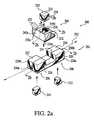
- FIG. 2 ais a perspective assembly view of a second embodiment of the smart sensor assembly of the invention.
- FIG. 2 bis a cross-sectional view of the sensor assembly housing of FIG. 2, taken along lines 2 — 2 .
- FIG. 2 cis perspective view of the sensor assembly of FIG. 2 a , shown installed within a gimbal assembly.
- FIG. 3is a top plan view of a third embodiment of the sensor assembly of the invention, having both removable/disposable pressure and ultrasonic transducers.
- FIG. 4is a functional block diagram illustrating a first embodiment of a physiologic parameter measurement apparatus incorporating the smart sensor assembly of the invention.
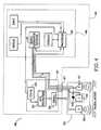
- FIG. 5is a logical block diagram of a second embodiment of the physiologic parameter measurement apparatus of the invention, including a wireless communications link.
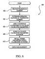
- FIG. 6is a logical flow diagram illustrating one exemplary embodiment of the method of calibrating a disposable sensor element according to the invention.
- FIG. 7is a schematic diagram of a first embodiment of the logic circuit of the invention.
- FIG. 8is a schematic diagram of a second embodiment of the logic circuit of the invention.
- FIG. 9is a flow diagram illustrating one embodiment of the method of evaluating the acceptability of the smart sensor assembly of the invention in conjunction with the physiologic parameter measurement apparatus of FIG. 4 .
- FIG. 10is a flow diagram illustrating one embodiment of the generalized method of encoding and storing data related to an applanation measurement performed on a patient within the sensor assembly of the invention.
- FIG. 11is a flow diagram illustrating one exemplary embodiment of the method of encoding physiologic parameters within the sensor of the present invention.
- FIG. 12is an exemplary plot of pressure and arterial blood velocity data which is encoded using the method of the present invention.
- the inventionis described herein in terms of a method and apparatus for assessing the hemodynamic parameters of the circulatory system via the radial artery (i.e., wrist) of a human subject, the invention may also be embodied or adapted to monitor such parameters at other locations on the human body, as well as monitoring these parameters on other warm-blooded species. All such adaptations and alternate embodiments are considered to fall within the scope of the claims appended hereto.
- the present inventiongenerally comprises a “smart” blood pressure sensor assembly which is used in conjunction with blood pressure system and host device in order to provide the enhanced functionality of the invention.
- This functionalityincludes, inter alia, (i) the ability to pre-store data relating to the manufacture, configuration, and calibration of the sensor assembly prior to use; (ii) the ability to use the pre-stored data to calibrate and enable/disable the sensor assembly during use, based on certain parameters and analyses conducted when the sensor assembly is connected to the host device; and (iii) the ability to store data obtained by the sensors or designated by the subject or caregiver within the sensor assembly and/or the host device during use.
- Each of these aspectsin one fashion or another enhances the accuracy and reliability of blood pressure measurements taken with the system, as described in greater detail in the following paragraphs.
- the sensor assembly 100 of this embodimentcomprises a cover 102 and main sensor housing 104 which are mated together to form the sensor body 106 .
- the shape of the cover 102 and sensor housing 104is generally that of an elongate rectangle, although it will be recognized that other shapes may be used.
- a mounting element 107is formed in the cover 102 to permit, inter alia, positional control of the assembly 100 by the local controller assembly 444 (FIG. 4 ), as well as an electrical penetration (not shown) for providing power for and data communication with the assembly 100 .
- the mounting elementis generally spherical or ball-shaped to permit the assembly to couple to the applanation mechanism 407 and operate in a variety of orientations with respect to the local controller 444 , although other arrangements (such as universal joints, Heim joints, etc.) well known in the mechanical arts may be used.
- the housing 104 and cover 102 of the illustrated embodimentare fabricated from a high strength, low cost polymer such as polycarbonate to provide the desired mechanical and electrical properties while still making the disposal of the assembly 100 economically feasible.
- a high strength, low cost polymersuch as polycarbonate
- Other materialsmay be substituted depending on the properties and attributes desired.
- the main housing 104 and cover 102enclose a number of components, including a printed circuit board (PCB) 108 , sensors in the form of a pressure transducer chip 110 and ultrasonic transducer (e.g., PZT) 112 , bonding ring 114 for the pressure transducer chip 110 , and storage device 116 .
- PCBprinted circuit board
- sensorsin the form of a pressure transducer chip 110 and ultrasonic transducer (e.g., PZT) 112 , bonding ring 114 for the pressure transducer chip 110 , and storage device 116 .
- the storage device 116 and pressure and ultrasonic transducers 110 , 112are mounted onto the PCB 108 in a manner well understood to those of ordinary skill in the electrical arts, although other arrangements may be used.
- EEPROMelectrically erasable programmable read only memory
- EPROMerasable PROM
- UVEPROMultraviolet EPROM
- SRAMDRAM
- SDRAMflash memory
- magnetic mediamay conceivably be used for a portion or all of the desired functionality.
- the storage device 116 chosen for use in the present embodimentis a 1K EEPROM device manufactured by Microchip Corporation, which operates from a 5 volt supply and utilizes a 2 wire serial link for data transfer.
- the 1K byte EEPROMis small in size and packaged in a SOT-23 package.
- This device 116allows for cost-effective non-volatile storage of up to 1024 bits of information organized as 128 8-bit words.
- the entire devicemay be written in a time period on the order of one second, thereby providing rapid storage capability.
- the devicealso nominally allows 1 million write cycles, thereby allowing for extended use within a given sensor. Data retention of the device is on the order of 100 years, thereby greatly exceeding the anticipated shelf life of the assembly 100 as a whole.
- the aforementioned EEPROMis easily accommodated within the sensor housing 104 on the PCB 108 . Connections are made in the present embodiment by wire bonding or alternate methods at the same time the pressure transducer is connected 110 , although other assembly and bonding methods may be used. A gel cup (not shown) or other means may optionally be used to protect the EEPROM 116 from electrostatic discharge or other electrical or physical trauma. Electrical signals are transferred in and out of the sensor assembly 100 using a plurality of electrical conductors (not shown) of the type well known in the art. Essentially any configuration of electrical connector or coupling may be substituted depending on the needs of the particular application.
- the sensor assembly 200 of the second embodimentcomprises a two-lobed first housing element 202 and a generally rectangular second housing element 204 , the two elements 202 , 204 fitting together to form a unitary assembly.
- the first element 202includes a pair of adapted recesses 206 , 208 in which at least a portion of respective ultrasonic transducer elements 210 , 212 are received.
- the second housing element 204similarly includes a recess 214 in which the pressure transducer 416 with associated storage device 218 is received.
- the pressure transducer 216comprises a silicon strain beam transducer element which generates an electrical signal in functional relationship (e.g., proportional) to the pressure applied to its sensing surface.
- the ultrasonic transducers 210 , 212comprises piezoelectric (ceramic) devices which are capable of both generating and receiving ultrasonic waves and/or pulses depending on mode.
- the ultrasonic transducers 210 , 212are tuned to generate ultrasonic frequencies centered at 8 MHz and 16 MHz respectively, although other center frequencies, with varying bandwidths, may be used.
- the transducer elements 210 , 212 , 216are frictionally received within the recesses of their respective housing elements 202 , 204 via an interference fit of the type well known in the art, although other arrangements (such as adhesives) may be used to retain the transducer elements in the desired position(s).
- the housing elements 202 , 204are formed from a low-cost thermoplastic such as polycarbonate although it will be recognized that other materials such as ethylene tetrafluoroethylene (i.e., Tefzel®), Teflon®, PVC, ABS, or even non-polymers may be substituted depending on the desired material and physical properties (such as rigidity, tensile strength, compatibility with certain chemical agents, ultrasonic transmission at certain wavelengths, etc.).
- the storage device 218 of FIG. 2 acomprises an EEPROM, although other types of devices including EPROM, UVEPROM, or even RAM may be substituted.
- the first and second housing elements 202 , 204are adapted to fit together such that the second element 204 is removable from the first element 202 .
- This aspect of the inventionallows for the removal of the pressure transducer element 216 and associated storage device 218 from the first housing element 202 , thereby rendering the former disposable if desired.
- the first housing element 202may also be made removable or separable from the local controller 444 (FIG. 4 ), such that both components are separately disposable (e.g., in the event that it is desired to operate one type of transducer element for a period different than that for the other type of transducer element).
- the second housing element 204“snaps” into a channel 220 formed in the first housing element 202 such that the contact surfaces 222 , 224 of each the first housing element and that of the pressure transducer 225 are in substantial planar alignment. In this fashion, the contact surfaces 222 , 224 , 225 each contact the skin (or interposed coupling medium) of the subject concurrently, allowing for ready coupling of each of the transducers to the subject.
- the snap functionality previously describedis accomplished using a series of transverse ridges 226 formed on exterior lateral surfaces 228 a , 228 b the first housing element coupled with the extending inner edges 230 a , 230 b of the removal tabs 232 formed on the corresponding sides of the second housing element 204 , although it will be appreciated that any other types of arrangements for retaining the second housing element 204 in a given physical relationship with the first housing element 202 may be utilized, such arrangements being well understood by those of ordinary skill in the mechanical arts.
- other types of snap arrangementssuch as one or more raised pins or protrusions, coupled with a complementary detent
- a frangible constructionmay be employed.
- an adhesivesuch as a non- permanent silicone-based adhesive, or a frictional interference construction may be used to retain the second housing element 204 within the first 202 .
- the removal tabs 232 of the second housing element 204are constructed such that when the tabs are grasped by the user (such as between the thumb and forefinger) and compressed slightly, the extending inner edges 230 a , 230 b of the tabs 232 disengage slightly from the transverse ridges 226 , thereby allowing the second housing element 204 to be removed from the first 202 by pulling it vertically there from.
- the sidewalls 240 a , 240 b of the second housing elementare designed to allow sufficient flexibility such that when the tabs 232 are compressed, the sidewalls flex and disengage the inner edges 230 a , 230 b from their respective ridges 226 .
- the first and second housing elementsare also provided with a groove 234 and vertical ridge 236 formed on corresponding mating surfaces of the two components which act to align the second housing element properly, and in one orientation only, within the first housing element.
- the second housing element 204may only be received within the first element 202 in one orientation, such that the transducer elements 210 , 212 , 216 are in proper alignment when the assembly 200 is properly assembled.
- the first housing element 202is further equipped with a pair of pivot pins 250 a , 250 b which are disposed linearly and parallel to the longitudinal axis 252 of the first element 202 .
- the pivot pins 250are received within respective bores (not shown) formed in a first support element 254 of the gimbal assembly 256 as shown in FIG. 2 c , the latter being mounted to the local controller device 444 (FIG. 4 ).
- This arrangementpermits the sensor assembly 200 to rotate around at least the longitudinal axis 252 , thereby allowing the active surface of the transducer element 216 (as well as the contact surfaces 222 , 224 of the first housing element 202 ) to orient themselves properly on the surface of the subject's skin.
- a secondary pivot arrangement 260 transverse to the axis 252is also provided with respect to a second support element 258 as shown, thereby allowing the sensor assembly 200 to rotate around the transverse axis 264 in the direction 266 .
- the sensor assembly 200when coupled to the gimbal 256 , the sensor assembly 200 is advantageously allowed three distinct degrees of freedom (two rotational, and one in the vertical or normal direction), which permits the ultrasonic transducer elements 210 , 212 and the pressure transducer 216 to be correctly oriented with respect to the skin of the subject at all times during the measurement, even when the subject moves during the measurement.
- FIGS. 2 a - 2 cincludes a generally two-lobed first housing element 202 and second housing element with a single transducer element 216
- a single ultrasonic transducer 310 and single pressure transducer 316can be used, the two transducers being aligned in a “side-by-side” configuration within the complementary housing elements 302 , 304 .
- FIGS. 1 a - 3are merely illustrative of the broader concept of having either or both the pressure transducer and/or ultrasonic transducer element(s) (with any associated storage device) being separable from the local controller and optionally disposable.
- an apparatus for assessing the physiologic parameters of a living subject and incorporating the “smart” sensor assembly of the present inventionis adapted for the measurement of blood pressure within the radial artery of a human being, although it will be recognized that other physiologic parameters, monitoring sites, and even types of living organism may be utilized in conjunction with the invention in a broader sense.
- the apparatus 400 of FIG. 4fundamentally comprises the sensor assembly previously described used in conjunction with a reusable “host” system 401 which controls and supports the operation of the sensor assembly. Specifically, the sensor assembly is contained within a local controller assembly 444 , which is coupled via electrical cable or other communications interface to a remote analysis and display station 446 . While the apparatus 400 of FIG. 4 having the sensor assembly 200 of FIGS. 2 a - 2 c is described in detail in the following paragraphs, it will be apparent that the assembly of FIGS. 1 a - 1 c , or alternatively yet another configuration, may be used with equal success.
- a pressure transducer 416for measuring blood pressure from the radial artery tonometrically; an applanation device 407 coupled to the transducer 416 for varying the degree of applanation (compression) on the artery; two ultrasonic transducers 410 , 412 for generating ultrasonic emissions and reflections thereof, these ultrasonic emissions being used to derive blood velocity (and kinetic energy); a signal processor 420 operatively connected to the pressure and ultrasonic transducers 416 , 410 , 412 for analyzing the signals generated by these transducers and generating a calibration function based thereon; a signal generator/receiver 422 used to generate ultrasonic signals for transmission into the artery, and receive signals from the ultrasonic transducers 410 , 412 ; and a controller 426 operatively coupled to the applanation device 407 and the signal processor 420 for controlling the degree of applanation pressure applied to the artery.
- the pressure and ultrasonic transducers 416 , 410 , 412are arranged within the sensor assembly 200 previously described with respect to FIG. 2 herein.
- the gimbal 256is coupled to the sensor assembly 200 and the applanation device 407 as shown in FIG. 2 c in order to transfer the applanation force from the device 407 to the sensor assembly 200 and ultimately to the skin of the subject.
- the applanation mechanism 407 and sensor assembly 200(along with apparatus necessary to maintain the sensor assembly 200 in position on the subject, such as a wrist brace or band) collectively comprise the local controller assembly 444 which is mounted on the subject's wrist, although it will be appreciated that other configurations may be substituted.
- the various signal processing and/or electronic componentssuch as the processor 420 and controller 426 may be located within the controller assembly 444 or alternatively located remotely from the subject such as in the monitoring and display station 446 if desired.
- the local controller assembly 444further includes portions of the logic circuit (as described below with respect to FIGS. 7 and 8 ), which compensates or calibrates the pressure transducer element 416 for offset, temperature effects, and non-linearities characteristic of each individual pressure transducer element. This calibration is advantageously conducted upon the initialization of each new pressure transducer element 416 and associated EEPROM device 418 , thereby assuring the adequacy and proper calibration of the apparatus 400 as a whole before use with that new transducer element.
- the analysis and display unit 446comprises display, data analysis, user control, and data storage functions for the apparatus 400 including the display of raw data sensed by the transducer elements, display of parameters calculated based on the raw data by the processor and associated signal processing algorithms, equipment status indications, display of information stored within the storage device 218 of the sensor assembly (such as pressure transducer manufacture date/location, calibration parameters, etc.), name/SSN of the subject being monitored, etc.
- the analysis and display stationcomprises a dedicated device having a CRT, TFT/LCD, LED, or plasma display coupled with a variety of pre-specified control and data storage functions.
- a laptop or handheld computerhaving software adapted for performing each of the foregoing functions, or those specifically chosen by the user, may be substituted.
- the signal generator/reciever 422generates electrical signals or pulses which are provided to the ultrasonic transducers 410 , 412 and converted into ultrasonic energy radiated into the blood vessel. This ultrasonic energy is reflected by various structures within the artery, includeing blood flowing therein, as well as tissue and other bodily components in proximity to the artery. These ultrasonic reflections (echoes) are recieved by the ultrasonic transducers and converted into electrical signals which are then converted by the signal generator/reciever 422 to a digital form (using, e.g., an ADC) and sent to the signal processor 420 for analysis.
- a digital formusing, e.g., an ADC
- the signal processorcomprises a microprocessor unit and a digital signal processor (DSP) unit (not shown) in order to facilitate, inter alis, rapid data processing and the control functionality previously described, although it will be recognized that the processor 420 may configured in other ways if desired.
- the signal processor 420utilizes its program (either embedded or stored in an external storage device) to anlyze the recieved signals. For example, if the system is used to measure the maximum blood velocity, then the recieved echoes are analyzed for, inter alia, Doppler frequency shift. Alternatively. if the arterial diameter (area) is measured, then an analysis appropriate to the aforementioned A-mode is employed.
- FIG. 5illustrates a second embodiment of the physiologic parameter measurement apparatus of the present invention.
- the system 500further includes a radio frequency (RF) transceiver chip 504 and associated processing of the type well known in the art for transmitting the information generated by the transducers elements 510 , 512 and stored within the storage device 518 to the host device via an associated antenna 506 located on the local control assembly 507 and receiver 508 located on the analysis and display device 523 .
- the antenna 506 and receiver 508ideally comprise transponders, thereby enabling two-way communication between the local control assembly 507 and the analysis and display unit 523 .
- the need for wiring or conductors communicating the electrical signals between the local control assembly 507 and the remote analysis and display unit 523is advantageously obviated, thereby allowing the patient additional mobility during blood pressure measurement, such as when being transferred from one location in a hospital to another.
- wireless transmission methodologiesair interfaces
- IrDAInfrared Data Association's
- RFwireless radio frequency
- LANlocal area network
- FIG. 6the method of calibrating a disposable transducer element such as that of FIGS. 2 a - 2 c using its associated storage device is described. It will be recognized that while the following discussion is cast in term of the calibration of a silicon strain beam pressure transducer element, the general principles described herein are equally applicable to wire strain gage transducer elements or yet even other types of sensor elements.
- the method 600comprises first providing a transducer element (such as the aforementioned pressure transducer 216 of the embodiment of FIG. 2) having a predetermined operating response per step 602 .
- the operating response of the transducer elementis determined in step 604 .
- the response of the transducer elementis determined by measuring, inter alia, the bridge voltage (E b ) and signal output voltage of the transducer element (E s ) under varying conditions of temperature and applied pressure. Specifically, E b and E s are measured for a series of increasing pressures at a first temperature T o , and then again at a higher or “hot” temperature T h . Table 1 below illustrates this principle graphically.
- This step 604is typically but not necessarily performed by the transducer vendor or manufacturer.
- step 606a series of conversion algorithms are applied to the “raw” transducer response data obtained in step 604 to convert the response data to calibration parameters useful for calibrating the pressure transducer in-situ during operation. Allowable ranges for the resulting calibration parameters are also specified.
- Table 2illustrates an exemplary set of calibration parameters, allowable ranges, and conversion algorithms for a typical silicon strain beam pressure transducer element.
- E refReference voltage used by vendor at measurement (V)
- T refReference temperature used by vendor (degrees C.)
- T h“High” temperature used by vendor during raw data measurement (degrees C.)
- V osOffset voltage of transducer (bridge) at zero applied pressure and Tref (mV)
- V osTCTemperature correction factor for offset voltage of bridge (mV/degree C.)
- E b0Bridge voltage at T ref (V)
- E b0TCTemperature correction factor for bridge voltage (mV/degree C.)
- SensSensitivity of bridge to pressure change (uV/mmHg)
- Lin ErrorLinearity error or non-linearity (%)
- E calShunted output voltage of bridge (mV)
- E refReference voltage used by vendor at measurement (V)
- T refReference temperature used by vendor (degrees C)
- T h“High” temperature used by vendor during raw data measurement (degrees C)
- V osOffset voltage of transducer (bridge) at zero applied pressure and Tref (mV)
- V osTCTemperature correction factor for offset voltage of bridge (mV/degree C)
- E b0TCTemperature correction factor for bridge voltage (mV/degree C)
- SensSensitivity of bridge to pressure change (uV/mmHg)
- the conversion algorithms of Table 2are derived based on the definition of the various calibration parameters (Table 3. below), and the raw transducer response data. For example, in the case of the temperature correction factor for the bridge voltage (E b0TC ), the bridge voltage taken at the reference temperature T 0 and zero pressure, or Eb 0 , is subtracted from the bridge voltage taken at the “hot” temperature “T h ” and zero pressure (E b4 ), the resultant of which is divided by the difference between the hot temperature and the reference temperature (i.e., T h minus T 0 ) to produce E b0TC .
- the derivation of the other conversion algorithmsis generally analogous, and easily determined by those of ordinary skill in the electronic arts.
- step 608the calculated calibrations parameters (Table 3 below) are stored within the storage device (e.g., EEPROM) of the transducer element for later recall during calibration/operation (step 610 ).
- Appendix Iillustrates exemplary code useful for extracting the calibration parameters of Table 3 for a pressure transducer element from the EEPROM associated therewith.
- FIG. 7a first embodiment of the logic circuit used for effectuating the calibration of the pressure transducer element(s) as described with respect to FIG. 6 above is disclosed.
- the circuit 700comprises an analog circuit having a pressure transducer element 216 represented in the form of an electrical bridge, an EEPROM 218 , a span compensation resistor R a , 720 , reference voltage E ref 703 , first and second analog-to-digital converters (ADC's) 702 , 750 , digital-to-analog converter (DAC) 704 , three operational amplifiers 706 , 708 , 710 of the type well known in the electronic arts, a system processor 760 , which can be any microprocessor, microcontroller, or even a DSP device, electronic analog switch 770 , and a precision shunt resistor R cal 780 .
- ADC'sanalog-to-digital converters
- DACdigital-to-analog converter
- the voltage output of the pressure transducer (bridge) 716is input to a first stage operational amplifier 706 which amplifies the output of the pressure transducer.
- the amplified outputis input to a second stage amplifier 708 , along with the output of the DAC 704 , which is subtracted from the transducer signal.
- the output of the second stage amplifier 708represents the temperature compensated, zero offset output signal of the circuit 700 .
- the system processor 760reads the data stored in the EEPROM 218 , and sets the DAC 704 to eliminate the offset. Since the offset is a function of temperature, the system processor 760 also reads the output of the first ADC 702 , which is sensing the bridge voltage E b of the pressure transducer 716 .
- the bridge voltagevaries with temperature, and the correlation between its variation wand the offset variation with temperature is stored in the EEPROM. Since this variation is small, it is amplified by the third stage amplifier 710 , before being read by the first ADC 702 .
- offsetrefers to the output voltage of the bridge 216 at zero applied pressure under specified conditions of temperature.
- the second ADC 750is used to convert the final analog output of the second stage amplifier 708 to a digital representation of the blood pressure.
- the system processorreads the EEPROM in the disposable transducer 216 , to obtain the transducer sensitivity (Sens). This factor is used to scale the output of second stage amplifier 708 in the digital domain so that a known relationship of the output of the amplifier 708 exists in mV per mmHg.
- the span compensating resistor R a 720value is chosen to be 1000 ohms based on the bridge impedance, span TC, and reference voltage E ref 703 , which is chosen to be 5 V. It will be recognized, however, that a range of values for R a are possible from a few hundred ohms to several thousand ohms. Reference voltages other than 5 V may also be used.
- the main functions of resistor R a 720are to temperature compensate the span sensitivity of the transducer to temperature, and to provide signal E b , which provides an output which is a function of the temperature of the bridge.
- the calibration and functionality of the transducer and the systemcan be checked by periodically turning on the analog switch 770 , which shunts one side of the bridge with precision resistor R cal 780 .
- this operationis initially performed at the time of manufacture, and the result is stored in the EEPROM as E cal .
- the resistor 780is selected to have a near zero TC, and a precise value that gives a response approximately equal to the equivalent of 100 mmHg.
- the system processorturns on the switch 770 and reads the output of the circuit 700 . It then compares the value obtained with E cal which is stored in the EEPROM. If the results match within specified limits, then system accuracy is ensured. Note that this calibration verification generally is performed when the sensor is off the wrist of the subject. Since the system can control and sense the applanation of the sensor, this condition is ensured, and calibration will typically be checked prior to a blood pressure measurement interval.
- the bridge voltage E b of the circuit 700is sampled at an interval of once per second, and the input value to the DAC recalculated in order to continually update the DAC output provided to the second stage amplifier 708 . In this fashion, the output of the bridge (transducer element) is continually compensated for temperature.
- portions of the functionality of the circuit of FIG. 7are alternatively accomplished using higher resolution first and second A/D converters 802 , 850 to read the output of the bridge amplifier 806 , and the bridge voltage E b .
- the embodiment of FIG. 8digitizes both the signal and the error terms, and does the subtraction in software running on the system processor 860 , as is well known in the art. Temperature variations of the bridge 216 are sensed by reading E b with the first ADC 802 . Corrections to the output signal are accomplished in the digital domain by the system processor 860 .
- one A/D converter and an analog multiplexerare used in place of the first A/D converters 802 , 850 of the embodiment of FIG. 8 .
- Appendix IIhereto illustrates various exemplary applications of the smart sensor assembly of the invention, including storing data that enhances sensor and system performance and reliability. It is noted that the applications described in Appendix II are not exhaustive, but rather merely illustrative of the broader concept of the invention disclosed herein.
- Items 1 through 17 thereinrepresent exemplary data that is encoded on the EEPROM during sensor manufacturing according to the present embodiment. Each of these items is described in greater detail below with reference to Appendix I. Note that each of these Items can be considered optional, and furthermore that other configurations (such as different coding schemes, ranges/bits assigned to each parameter, etc.) may be used consistent with the invention.
- Datais encrypted on the EEPROM 116 using a 32-bit encryption key of the type well known in the cryptographic arts. This encryption frustrates unauthorized access to the data present on the EEPROM after encoding.
- datais encrypted on the EEPROM using a 32-bit key, and a 32-bit vendor verification code (Appendix II, Item 2). Unless the verification code matches, the system will reject the sensor as a non-matching or non-acceptable sensor.
- the encryption keyis the public part of the key. It is combined with the private part known only to the sensor vendor and customer, and is used to encrypt the data stored on the EEPROM. Sensors which have data which is not encrypted or encrypted incorrectly are rejected by the system upon startup.
- a 32-bit hexadecimal vendor verification codeis provided within the EEPROM 116 . Unless the verification code of the sensor assembly matches that stored in the host system 401 (FIG. 4 ), the host system will reject the sensor as being non-compatible. In this fashion, use of the sensor assembly with a non-compatible host, or vice versa, is prevented, thereby removing a potential source of error in the blood pressure readings obtained from a subject.
- the manufacturing locationis encoded on the sensor. Up to 255 different locations may be coded in the illustrated embodiment. This information may be used for inventory purposes, to track defective lots of items, etc.
- the date of manufactureis encoded. This date along with the real date derived from a real time clock chip (not shown) in the sensor/blood pressure measuring instrument allows rejection of any sensor assembly that is beyond its shelf life specification (for example, 2 years) when the sensor is connected to instrument. Hence, an “out of date” sensor assembly cannot be used with any host device, even if compatible.
- the vendor lot codeis encoded in the sensor. Since the manufacturing date and location is also encoded, multiple lots per day can be tracked using the present invention.
- a unique serial number for each senor assembly (and/or each specified transducer element)may also be encoded.
- the 32-bit field of the illustrated embodimentallows up to 4.295 billion combinations.
- Items 7-15characterize the performance of the transducer and allow calibration, linearization, and temperature compensation of the transducer when it is connected to the system. As illustrated in Appendix II, Items 7-15 represent the values of V ref , T o , T h , and V os , V os TC , E b0 , E b0TC , Sens, E cal , and Lin Error, respectively, as previously described with respect to FIG. 6 . Each sensor will have unique values for these items due to manufacturing tolerances. Note that E b0 and E b0TC advantageously allow the system the ability to measure the temperature of the sensor directly, and perform calibration of the system based thereon. When used on the radial artery, this temperature will be approximately equal to the patient skin temperature at the wrist when the sensor is in contact with the wrist.
- a common validation test for pressure transducersis to shunt one side of the bridge with a precision resistor, which causes the bridge to output a full-scale reading. In the present embodiment, this procedure is performed at the time of manufacture, and the actual resulting bridge output for each sensor assembly (as well as any critical test parameters, if desired) encoded into its corresponding EEPROM 116 . This same test is then performed in the blood pressure measuring system when the sensor is connected thereto, which validates the accuracy of the sensor electronically. The result of this validation is also optionally stored in the sensor storage device.
- the ultrasound signals generated by the ultrasonic transducer elementsare processed by the system and play a fundamental role in both the placement and positioning of the transducer element(s) and the accuracy of the pressure signal derived from the pressure transducer.
- a “quality” factor for these processed signalsis stored in the EEPROM. This quality factor is derived by the signal processing algorithms and represents the S/N (signal to noise ratio) of the ultrasound signals, as is well known. The higher the S/N, the better accuracy the overall system can achieve.
- Items 18 through 35 thereinrepresent exemplary data that the exemplary ultrasonic blood pressure measuring system used in conjunction with the sensor of the present invention writes to the EEPROM 116 during the time that the sensor assembly is connected to the host system. These items are described in greater detail below.
- the host systemWhen a sensor is first connected to the blood pressure measuring system, the host system reads the first “n” (e.g., 10) items from the sensor's storage device 116 , and first validates that the transducer is a compatible sensor as previously described. The host system then utilizes the sensor calibration information to adjust the system electronics accordingly to optimize the performance of the system for that sensor. The date and time of first connection is also written to the sensor. Once this occurs, the pressure calibration validation test of the present embodiment is performed which mimics the test performed at the time of manufacturing by shunting the bridge with the same value used on the sensor manufacturing line. The result is stored in the sensor.
- the first “n”e.g. 10
- the measuring systemalso optionally includes separate EEPROMs or other storage devices in, inter alia, the sensor positioning head and the system enclosure, which allows these devices to retain unique information such as their own serial numbers or calibration parameters. Such serial numbers may also be stored in the sensor, thereby allowing for tracing the specific measuring system/positioning head the sensor was being used with at a given time.
- the total time that the sensor is in an electrically powered stateis also stored in the sensor.
- this data fieldis updated within the storage device at periodic intervals (such as every minute), although other schemes for triggering updates, and update frequencies, may be used if desired.
- the total time that the sensor is performing measurements while poweredmay also be stored in the sensor storage device. As above, this field is updated on at a periodic interval.
- the remaining allocated power on timemay also be written to the sensor storage device.
- this timeis the measurement time (such as 24 hours) plus an additional time (3 hours, for example) to support device setup, although other arrangements may be used.
- the remaining run timemay also be stored in the sensor storage device.
- this fieldis the difference between 24 hours and the actual run time.
- the fieldis optionally updated on a periodic basis as previously described.
- the total number of measurement eventsis also stored in the sensor storage device.
- One measurement eventis defined in the present embodiment as the start of a measurement cycle to the end of a measurement cycle.
- the cyclecan be any length of time.
- the total number of “power on” cycles that a sensor seesis stored in the sensor storage device.
- the power on/off switch on the instrumentis electronic in nature, thereby facilitating counting the number of such events and storing them within the EEPROM.
- the voltage at a certain node within the circuitryis sensed; when the voltage level exceeds a predetermined value (corresponding to the fully powered-up state of the sensor), another event is recorded. Many other arrangements are possible, all being well understood by those of ordinary skill in the electronic arts.
- the sensor replacement codeis also stored in the sensor. Examples of sensor replacement codes are shown in the Table 5 herein.
- a utilization window of a predetermined intervale.g., 30 hours
- the sensorwere not used during the interval, it would expire concurrent with the expiration of the interval.
- shorter periods corresponding to power-on time and measurement timemay be defined. For example, up to 24 hours of actual measurement time, and 27 hours of actual power up time, would be allowed during the aforementioned 30 hour interval.
- failure analysismay be performed on one or more subsets of a given sensor population (such as those sensors which failed during use over a given period of time at a given health care facility).
- the contents of the sensor's EEPROMmay be downloaded to allow analysis of the individual failures. For example, if a large percentage of the aforementioned sensor failures occurred when the sensors were connected to a particular mechanism, the likely source of the failures, i.e., the common mechanism, could be divined as uniquely identified by its EEPROM serial number.
- Other scenariosare possible, all considered to be within the scope of the present invention.
- the blood pressure measurement systemperiodically checks the pressure sensor calibration (ideally, not during measurements) and write the result of one or more such tests to the sensor storage device. Also, during measurements, the system periodically writes the blood pressure, applanation value, and time and date to the sensor storage device. This data is subsequently retrievable and useful in evaluating the actual performance of the sensor and the measurement system, which might prove useful in a variety of circumstances (such as, inter alia, medical malpractice or products liability litigation).
- Items 36 through 39 of Appendix IIillustrate additional data which may optionally be recorded within the storage device according to the present invention.
- These itemscan be configured by the health care provider/physician if desired.
- the hospital name and care unit as well as the patient name and attendingmay be entered into the storage device(s) of the sensor and/or measurement system. If the hospital staff wanted to be sure that a sensor was only used on one patient, or only on a particular individual, or only within a specific ward or department (such as the Operating Room or Intensive Care Unit), the system may be configured to facilitate this. If use outside of the allowed parameters was detected, the sensor would be rejected, and the appropriate replacement code stored in the sensor's EEPROM.
- the utilization of the sensorcan be controlled across multiple mechanisms, systems, and power down events. Additional protection may also be gained by downloading a write authorization code to the sensor. For example, if attempts were made to write to the sensor to reset its run time, and the correct write authorization code was not utilized, the system would reject the sensor.
- the 32-bit encryption algorithm previously describedfurther thwarts such attempts.
- Other security or cryptographic techniques well known in the artmay be used to implement this protective functionality as well.
- the method 900comprises a first step 902 of storing data within the storage device (e.g., EEPROM) of the sensor assembly.
- the datamay take on any number of forms including the serial number or other identifying data of the probe, its date of manufacture, powered-on time to date, etc. Such data may be loaded upon manufacture, during operation/testing, or both.
- step 904the smart sensor assembly is connected to the “host” ultrasonic measurement system 401 (FIG. 4) previously described.
- step 906the data stored within the sensor storage device is read by the host and evaluated for compatibility between sensor and host (e.g., is the sensor of the type designated for use with a particular host), remaining lifetime, suitability of application (e.g., is the sensor suitable for use with the given patient or at the location indicated by the host), etc. If the sensor assembly (or component thereof) is somehow incompatible or otherwise restricted from use with the host in step 908 , the host generates an indication of rejection (step 910 ) and optionally encodes data within the host and/or sensor assembly storage device to this effect per step 912 . The user is then prompted to change the sensor assembly or incompatible component in steps 914 and 916 .
- FIG. 10one embodiment of the data encoding and storage method of the present invention is described. While the following description is cast in terms of a tonometric non-invasive blood pressure measurement, it will be apparent to those of ordinary skill that the methodology of FIG. 10 may be adapted to other types of parametric measurements and devices.
- the method 1000comprises a first step 1002 of performing an applanation “sweep” using the ultrasonic blood pressure measurement system previously described.
- the pressure, velocity, and wall (diameter) datais analyzed per step 1004 .
- the “best fit” curves for the patientare determined per step 1006 .
- These best fit curvesare determined using any one of a number of different methods, one exemplary method being described herein with reference to FIG. 11 .
- step 1008the patient is again applanated using the measurement system to determine the adequacy of the curves generated in step 1006 . If the curves are adequate (as based on predetermined criteria such as those described below with reference to FIG. 11, or other selected criteria) in step 1010 , the curves are then stored per step 1012 in the storage device of the sensor assembly. Stored data may include the measured pressure, blood velocity, and arterial diameter, or any other parameters related to the applanation as desired.
- the method 1100comprises collecting pressure and velocity data from a given patient using the sensor 1100 to perform applanation sweeps per step 1102 .
- step 1104the data obtained during step 1102 is analyzed using the aforementioned time-frequency or hemodynamic parameter measurement methods as set forth in Applicant's aforementioned copending U.S. patent applications previously incorporated herein, although it will be recognized that other methods of analysis may be substituted.
- the result of this analysisis an estimate of mean blood pressure within the measured patient.
- steps 1102 and 1104are repeated in order to derive a second estimate of the mean blood pressure.
- step 1108the two preceding estimates of mean blood pressure are evaluated to determine if they fall within predetermined acceptance criteria.
- the allowance band of 5 mm Hgi.e., the last two estimates must be within 5 mm Hg of each other
- This step 1108provides reasonable assurance that the sensor is placed correctly on the subject, is being used on the same patient (i.e., the disposable sensor assembly is not being reused on another subject), and the data is not corrupted.
- the collected data(including for example mean pressure, heart rate, peak blood flow at mean pressure, kinetic energy, arterial diameter at mean pressure, and transform peak values) are stored in the EEPROM or other storage device previously described.
- This datacollectively (or subsets thereof) comprises a characteristic signature for a given sensor assembly and patient.
- the plot 1200illustrates the applanation (pressure) sweep 1202 as a function of the number of samples; note that per the illustrated embodiment, a sampling rate of 200 samples per second is chosen, although other rates or even variable rates may be used. Also illustrated is the blood flow/velocity profile 1204 as a function of the number of samples.
Landscapes
- Health & Medical Sciences (AREA)
- Life Sciences & Earth Sciences (AREA)
- Engineering & Computer Science (AREA)
- Molecular Biology (AREA)
- Animal Behavior & Ethology (AREA)
- Veterinary Medicine (AREA)
- Biophysics (AREA)
- Pathology (AREA)
- Public Health (AREA)
- Biomedical Technology (AREA)
- Heart & Thoracic Surgery (AREA)
- Medical Informatics (AREA)
- General Health & Medical Sciences (AREA)
- Surgery (AREA)
- Physics & Mathematics (AREA)
- Cardiology (AREA)
- Physiology (AREA)
- Nuclear Medicine, Radiotherapy & Molecular Imaging (AREA)
- Radiology & Medical Imaging (AREA)
- Vascular Medicine (AREA)
- Hematology (AREA)
- Radar, Positioning & Navigation (AREA)
- Dentistry (AREA)
- Oral & Maxillofacial Surgery (AREA)
- Measuring Pulse, Heart Rate, Blood Pressure Or Blood Flow (AREA)
Abstract
Description
| TABLE 1 | ||||||
| Temp. | Press | Eb | Es | Er | Es-15K | |
| oC. | mmHg | V | mV | V | mV | |
| To | 0 | Ebo | Eso | Eref | ||
| To | P1 | |||||
| 50 | Eb1 | Es1 | ||||
| To | P2 | |||||
| 100 | Eb2 | Es2 | Eref | |||
| To | 300 | Eb3 | Es3 | |||
| Th | P4 | |||||
| 0 | Eb4 | Es4 | ||||
| Th | P5 | |||||
| 50 | Eb5 | Es5 | ||||
| Th | P6 | |||||
| 100 | Eb6 | Es6 | ||||
| Th | P7 | |||||
| 300 | Eb7 | Es7 | Eref | |||
| TABLE 2 | |||
| Calculations for EEPROM | Range | Resolution | Units |


| TABLE 3 |
| EEPROM DATA |
| Er | 5.002 | V | ||
| To | 24.9 | oC | ||
| Th | 40.0 | oC | ||
| Vos | 3.4999 | mV | ||
| Vos TC | 29.9 | uV/oC | ||
| Ebo | 1.4999 | V | ||
| Ebo TC | 1.960 | mV/oC | ||
| Sens | 80.0 | uV/mmHg | ||
| Lin Error | −1.99 | Percent | ||
| Ecal | 10.60 | mV | ||
| TABLE 4 | ||
| Error | ||
| 0 | ||
| 1 | ||
| 2 | EEPROM read/write failure | |
| 3 | US sensor failure | |
| 4 | Cal Test Failure | |
| 5 | Railed High | |
| 6 | Railed Low | |
| 7 | (Reserved) | |
| 8 | (Reserved) | |
| 9 | (Reserved) | |
| TABLE 5 | ||
| Error | ||
| 0 | |
| 1 | |
| 2 | 24 Hr measurement time expired |
| 3 | 27 Hr power on time expired |
| 4 | 30 Hr utilization time expired |
| 5 | Shelf life expired |
| 6 | Wrong mechanism |
| 7 | Wrong instrument |
| 8 | Wrong Patient |
| 9 | Wrong Unit |
| 10 | Wrong Hospital |
| 11 | (Reserved) |
Claims (21)
Priority Applications (2)
| Application Number | Priority Date | Filing Date | Title |
|---|---|---|---|
| US09/652,626US6676600B1 (en) | 1999-09-03 | 2000-08-31 | Smart physiologic parameter sensor and method |
| US10/754,414US20050049501A1 (en) | 1999-09-03 | 2004-01-09 | Smart physiologic parameter sensor and method |
Applications Claiming Priority (2)
| Application Number | Priority Date | Filing Date | Title |
|---|---|---|---|
| US15253499P | 1999-09-03 | 1999-09-03 | |
| US09/652,626US6676600B1 (en) | 1999-09-03 | 2000-08-31 | Smart physiologic parameter sensor and method |
Related Child Applications (1)
| Application Number | Title | Priority Date | Filing Date |
|---|---|---|---|
| US10/754,414DivisionUS20050049501A1 (en) | 1999-09-03 | 2004-01-09 | Smart physiologic parameter sensor and method |
Publications (1)
| Publication Number | Publication Date |
|---|---|
| US6676600B1true US6676600B1 (en) | 2004-01-13 |
Family
ID=29782235
Family Applications (2)
| Application Number | Title | Priority Date | Filing Date |
|---|---|---|---|
| US09/652,626Expired - LifetimeUS6676600B1 (en) | 1999-09-03 | 2000-08-31 | Smart physiologic parameter sensor and method |
| US10/754,414AbandonedUS20050049501A1 (en) | 1999-09-03 | 2004-01-09 | Smart physiologic parameter sensor and method |
Family Applications After (1)
| Application Number | Title | Priority Date | Filing Date |
|---|---|---|---|
| US10/754,414AbandonedUS20050049501A1 (en) | 1999-09-03 | 2004-01-09 | Smart physiologic parameter sensor and method |
Country Status (1)
| Country | Link |
|---|---|
| US (2) | US6676600B1 (en) |
Cited By (82)
| Publication number | Priority date | Publication date | Assignee | Title |
|---|---|---|---|---|
| US20020055680A1 (en)* | 1999-06-29 | 2002-05-09 | Miele Frank R. | Method and apparatus for the noninvasive assessment of hemodynamic parameters including blood vessel location |
| US20030141916A1 (en)* | 2002-01-30 | 2003-07-31 | Take Action | Apparatus and method for interfacing time-variant signals |
| US20040092801A1 (en)* | 2002-11-13 | 2004-05-13 | Budimir Drakulic | System for, and method of, acquiring physiological signals of a patient |
| US20040171935A1 (en)* | 2004-03-12 | 2004-09-02 | Siemens Medical Solutions Usa, Inc. | Ultrasound transducer probe identification for security and other purposes |
| US20040171982A1 (en)* | 2002-10-16 | 2004-09-02 | Marc Danchin | Single use device for transmitting information |
| US20040267103A1 (en)* | 2001-10-22 | 2004-12-30 | Luya Li | Physiological parameter monitoring system and sensor assembly for same |
| US20050080345A1 (en)* | 2002-10-11 | 2005-04-14 | Finburgh Simon E. | Apparatus and methods for non-invasively measuring hemodynamic parameters |
| US20060079792A1 (en)* | 2004-10-07 | 2006-04-13 | Finburgh Simon E | Compact apparatus and methods for non-invasively measuring hemodynamic parameters |
| US20060116588A1 (en)* | 1993-11-09 | 2006-06-01 | Archibald G K | Method and apparatus for calculating blood pressure of an artery |
| US20060136170A1 (en)* | 2004-12-21 | 2006-06-22 | Caterpillar Inc. | Position sensing system |
| US20060184051A1 (en)* | 2002-10-11 | 2006-08-17 | Hempstead Russell D | Apparatus and methods for non-invasively measuring hemodynamic parameters |
| US20060211942A1 (en)* | 2005-03-17 | 2006-09-21 | Hoctor Ralph T | Continuous, non-invasive technique for determining blood pressure using a transmission line model and transcutaneous ultrasound measurements |
| FR2883239A1 (en) | 2005-03-21 | 2006-09-22 | Faurecia Sieges Automobile | Safety assembly for child safety seat in motor vehicle, has electrical detection devices connected to electrical conducting units when child safety seat is in fixed position for detecting resistance wires and resistance |
| US20070078298A1 (en)* | 2003-07-02 | 2007-04-05 | Arkady Glukhovsky | Imaging sensor array and device and method for use thereof |
| US20070085690A1 (en)* | 2005-10-16 | 2007-04-19 | Bao Tran | Patient monitoring apparatus |
| US20070265535A1 (en)* | 2003-06-26 | 2007-11-15 | Sullivan Patrick K | Radiation Stress Non-Invasive Blood Pressure Method |
| US20070265533A1 (en)* | 2006-05-12 | 2007-11-15 | Bao Tran | Cuffless blood pressure monitoring appliance |
| US20070276270A1 (en)* | 2006-05-24 | 2007-11-29 | Bao Tran | Mesh network stroke monitoring appliance |
| US20070273504A1 (en)* | 2006-05-16 | 2007-11-29 | Bao Tran | Mesh network monitoring appliance |
| US20070287925A1 (en)* | 2006-05-13 | 2007-12-13 | Katayama Andrew S | Continuous positioning apparatus and methods |
| US20080004904A1 (en)* | 2006-06-30 | 2008-01-03 | Tran Bao Q | Systems and methods for providing interoperability among healthcare devices |
| US20080021334A1 (en)* | 2006-07-19 | 2008-01-24 | Finburgh Simon E | Apparatus and methods for non-invasively measuring hemodynamic parameters |
| US20080185419A1 (en)* | 2006-05-19 | 2008-08-07 | Smith Kevin W | Electrically Self-Powered Surgical Instrument With Cryptographic Identification of Interchangeable Part |
| US20080251569A1 (en)* | 2006-05-19 | 2008-10-16 | Smith Kevin W | Optimal Tissue Compression Electrical Surgical Instrument |
| US20080281168A1 (en)* | 2005-01-13 | 2008-11-13 | Welch Allyn, Inc. | Vital Signs Monitor |
| US20080294019A1 (en)* | 2007-05-24 | 2008-11-27 | Bao Tran | Wireless stroke monitoring |
| US7502498B2 (en) | 2004-09-10 | 2009-03-10 | Available For Licensing | Patient monitoring apparatus |
| US20090069698A1 (en)* | 2007-09-06 | 2009-03-12 | Samsung Electronics Co., Ltd. | Blood pressure measuring apparatus and method of measuring blood pressure |
| US20090240273A1 (en)* | 2008-03-24 | 2009-09-24 | Tyco Healthcare Group Lp | Surgical Introducer with Indicators |
| US20090260418A1 (en)* | 2002-07-23 | 2009-10-22 | Apieron, Inc. | Disposable sensor for use in measuring an analyte in a gaseous sample |
| US20100056932A1 (en)* | 2004-07-08 | 2010-03-04 | Edwards Lifesciences Corporation | Disposable Blood Pressure Transducer And Monitor Interface |
| US20100096431A1 (en)* | 2007-02-12 | 2010-04-22 | Ethicon Endo-Surgery, Inc. | Active braking electrical surgical iinstrument and method for braking such an instrument |
| EP2324759A1 (en)* | 2009-11-24 | 2011-05-25 | General Electric Company | Method and computer program for authenticating a physiological sensor, a sensor system, a patient monitor, and a physiological sensor |
| US20110210156A1 (en)* | 2005-07-26 | 2011-09-01 | Smith Kevin W | Electrically Self-Powered Surgical Instrument With Manual Release |
| US20110214280A1 (en)* | 2010-03-08 | 2011-09-08 | Masimo Corporation | Reprocessing of a physiological sensor |
| US20120089034A1 (en)* | 2009-06-22 | 2012-04-12 | Koninklijke Philips Electronics N.V. | Non-invasive blood pressure monitoring systems |
| US8323189B2 (en) | 2006-05-12 | 2012-12-04 | Bao Tran | Health monitoring appliance |
| EP2486863A3 (en)* | 2006-05-19 | 2013-01-09 | Ethicon Endo-Surgery, Inc. | Electrical surgical instrument |
| US8461988B2 (en) | 2005-10-16 | 2013-06-11 | Bao Tran | Personal emergency response (PER) system |
| US8500636B2 (en) | 2006-05-12 | 2013-08-06 | Bao Tran | Health monitoring appliance |
| CN103445762A (en)* | 2012-05-31 | 2013-12-18 | 通用电气公司 | Sensor validation,physiological sensor,patient monitor,and computer program product thereof |
| US8676612B2 (en)* | 2003-09-04 | 2014-03-18 | Hartford Fire Insurance Company | System for adjusting insurance for a building structure through the incorporation of selected technologies |
| US8684900B2 (en) | 2006-05-16 | 2014-04-01 | Bao Tran | Health monitoring appliance |
| US8684922B2 (en) | 2006-05-12 | 2014-04-01 | Bao Tran | Health monitoring system |
| US20150032029A1 (en)* | 2009-12-04 | 2015-01-29 | Masimo Corporation | Calibration for multi-stage physiological monitors |
| US8968195B2 (en) | 2006-05-12 | 2015-03-03 | Bao Tran | Health monitoring appliance |
| US9050001B2 (en) | 2012-03-29 | 2015-06-09 | DePuy Synthes Products, Inc. | Reading device in wired communication with a probe having an embedded memory device |
| US9060683B2 (en) | 2006-05-12 | 2015-06-23 | Bao Tran | Mobile wireless appliance |
| US9131882B2 (en) | 2005-03-01 | 2015-09-15 | Cercacor Laboratories, Inc. | Noninvasive multi-parameter patient monitor |
| US9138180B1 (en) | 2010-05-03 | 2015-09-22 | Masimo Corporation | Sensor adapter cable |
| US9301730B2 (en) | 2005-04-18 | 2016-04-05 | Koninklijke Philips N.V. | Ultrasonic diagnostic imaging system configured by probe firmware |
| EP2538843B1 (en) | 2010-02-24 | 2016-09-14 | Edwards Lifesciences Corporation | Body parameter sensor and monitor interface |
| US9554803B2 (en) | 2005-07-26 | 2017-01-31 | Ethicon Endo-Surgery, Llc | Electrically self-powered surgical instrument with manual release |
| US9655530B2 (en) | 2011-04-29 | 2017-05-23 | Tensys Medical, Inc. | Apparatus and methods for non-invasively measuring physiologic parameters of one or more subjects |
| US9662116B2 (en) | 2006-05-19 | 2017-05-30 | Ethicon, Llc | Electrically self-powered surgical instrument with cryptographic identification of interchangeable part |
| US20170156706A1 (en)* | 2014-06-20 | 2017-06-08 | Healthcare Technology Innovation Centre | Method and system for cuff-less blood pressure (bp) measurement of a subject |
| US20170224228A1 (en)* | 2014-10-31 | 2017-08-10 | Omron Healthcare Co., Ltd. | Blood pressure measurement device |
| US9848807B2 (en) | 2007-04-21 | 2017-12-26 | Masimo Corporation | Tissue profile wellness monitor |
| US9865176B2 (en) | 2012-12-07 | 2018-01-09 | Koninklijke Philips N.V. | Health monitoring system |
| US9949676B2 (en) | 2006-10-12 | 2018-04-24 | Masimo Corporation | Patient monitor capable of monitoring the quality of attached probes and accessories |
| US20180310834A1 (en)* | 2016-01-08 | 2018-11-01 | Omron Healthcare Co., Ltd. | Pressure pulse wave measurement apparatus and bodily information measurement apparatus |
| US20180325383A1 (en)* | 2016-01-08 | 2018-11-15 | Omron Healthcare Co., Ltd. | Pressure pulse wave measurement apparatus and bodily information measurement apparatus |
| US10314583B2 (en) | 2005-07-26 | 2019-06-11 | Ethicon Llc | Electrically self-powered surgical instrument with manual release |
| US10517489B2 (en) | 2014-09-08 | 2019-12-31 | Apple Inc. | Wrist worn accelerometer for pulse transit time (PTT) measurements of blood pressure |
| WO2020075190A1 (en)* | 2018-10-10 | 2020-04-16 | Ibrum Technologies | An intelligent cardio-pulmonary screening device for telemedicine applications |
| US10702171B2 (en) | 2014-09-08 | 2020-07-07 | Apple Inc. | Systems, devices, and methods for measuring blood pressure of a user |
| US10772512B2 (en) | 2014-09-08 | 2020-09-15 | Apple Inc. | Blood pressure monitoring using a multi-function wrist-worn device |
| US10779738B2 (en) | 2014-09-08 | 2020-09-22 | Apple Inc. | Electrical coupling of pulse transit time (PTT) measurement system to heart for blood pressure measurement |
| US10794739B2 (en)* | 2015-10-28 | 2020-10-06 | Nokia Technologies Oy | Apparatus and method of forming a sensor array using the apparatus |
| US10952675B2 (en) | 2007-10-12 | 2021-03-23 | Shangyi Medical Technology (Hangzhou) Co., Ltd | Apparatus and methods for non-invasively measuring a patient's arterial blood pressure |
| US11029198B2 (en)* | 2015-06-01 | 2021-06-08 | The Board Of Trustees Of The University Of Illinois | Alternative approach for UV sensing |
| US11118965B2 (en) | 2015-06-01 | 2021-09-14 | The Board Of Trustees Of The University Of Illinois | Miniaturized electronic systems with wireless power and near-field communication capabilities |
| US11134852B2 (en)* | 2016-04-14 | 2021-10-05 | Omron Healthcare Co., Ltd. | Pressure pulse wave detector and biometric information measurement device |
| US11166637B2 (en)* | 2017-01-18 | 2021-11-09 | Stryker Corporation | Non-invasive blood pressure measurement using pulse wave velocity |
| US11357415B2 (en) | 2017-10-27 | 2022-06-14 | Stryker Corporation | Light-based non-invasive blood pressure systems and methods |
| US11413005B2 (en) | 2017-08-14 | 2022-08-16 | Stryker Corporation | Constitutive equation for non-invasive blood pressure measurement systems and methods |
| US11534087B2 (en) | 2009-11-24 | 2022-12-27 | Cercacor Laboratories, Inc. | Physiological measurement system with automatic wavelength adjustment |
| US11751873B2 (en) | 2005-07-26 | 2023-09-12 | Cilag Gmbh International | Electrically powered surgical instrument with manual release |
| US12009166B2 (en) | 2006-05-19 | 2024-06-11 | Cilag Gmbh International | Force switch |
| US12029586B2 (en) | 2006-10-12 | 2024-07-09 | Masimo Corporation | Oximeter probe off indicator defining probe off space |
| US12059150B2 (en) | 2005-07-26 | 2024-08-13 | Cilag Gmbh International | Surgical stapling and cutting device |
| US12279867B2 (en) | 2017-08-18 | 2025-04-22 | Abbott Diabetes Care Inc. | Systems, devices, and methods related to the individualized calibration and/or manufacturing of medical devices |
Families Citing this family (21)
| Publication number | Priority date | Publication date | Assignee | Title |
|---|---|---|---|---|
| NL1021054C1 (en)* | 2002-07-12 | 2004-01-13 | Best Medical Internat Beheer B | Universal measuring device for medical application. |
| ATE479343T1 (en) | 2002-10-01 | 2010-09-15 | Nellcor Puritan Bennett Inc | USE OF A HEADBAND FOR VOLTAGE DISPLAY AND SYSTEM OF OXYMETER AND HEADBAND |
| US7047056B2 (en) | 2003-06-25 | 2006-05-16 | Nellcor Puritan Bennett Incorporated | Hat-based oximeter sensor |
| US7976475B2 (en)* | 2003-09-12 | 2011-07-12 | Laborie Medical Technologies, Inc. | Method for preparation and use of a two part medical measurement device |
| US8412297B2 (en) | 2003-10-01 | 2013-04-02 | Covidien Lp | Forehead sensor placement |
| US7545272B2 (en) | 2005-02-08 | 2009-06-09 | Therasense, Inc. | RF tag on test strips, test strip vials and boxes |
| US8456301B2 (en) | 2007-05-08 | 2013-06-04 | Abbott Diabetes Care Inc. | Analyte monitoring system and methods |
| US8160900B2 (en) | 2007-06-29 | 2012-04-17 | Abbott Diabetes Care Inc. | Analyte monitoring and management device and method to analyze the frequency of user interaction with the device |
| DE102007039530A1 (en)* | 2007-08-21 | 2009-02-26 | Endress + Hauser Conducta Gesellschaft für Mess- und Regeltechnik mbH + Co. KG | Method for compatibility testing of a measuring system consisting of a transmitter and a sensor |
| US8364220B2 (en) | 2008-09-25 | 2013-01-29 | Covidien Lp | Medical sensor and technique for using the same |
| US8257274B2 (en) | 2008-09-25 | 2012-09-04 | Nellcor Puritan Bennett Llc | Medical sensor and technique for using the same |
| US20100222649A1 (en)* | 2009-03-02 | 2010-09-02 | American Well Systems | Remote medical servicing |
| US8515515B2 (en) | 2009-03-25 | 2013-08-20 | Covidien Lp | Medical sensor with compressible light barrier and technique for using the same |
| US8781548B2 (en) | 2009-03-31 | 2014-07-15 | Covidien Lp | Medical sensor with flexible components and technique for using the same |
| US8525643B2 (en)* | 2010-03-02 | 2013-09-03 | Medtronic, Inc. | Medical system with identification patch |
| USD672031S1 (en)* | 2010-11-04 | 2012-12-04 | The Hunt Project, Llc | Medicinal delivery device |
| US20140122108A1 (en)* | 2012-10-25 | 2014-05-01 | Analyte Health, Inc. | System and Method for Coordinating Payment for Healthcare Services |
| WO2015100109A1 (en) | 2013-12-27 | 2015-07-02 | Abbott Diabetes Care Inc. | Systems, devices, and methods for authentication in an analyte monitoring environment |
| JP6767780B2 (en)* | 2016-06-01 | 2020-10-14 | オムロンヘルスケア株式会社 | Biological information measuring device, method for determining the validity of biological information, and a program for determining the validity of biological information |
| US12335342B2 (en) | 2020-07-21 | 2025-06-17 | Abbott Diabetes Care Inc. | Transmitting analyte data using low-power instruction sets |
| WO2022047411A1 (en) | 2020-08-31 | 2022-03-03 | Abbott Diabetes Care Inc. | Secured communications in medical monitoring systems |
Citations (33)
| Publication number | Priority date | Publication date | Assignee | Title |
|---|---|---|---|---|
| US3724274A (en)* | 1971-02-11 | 1973-04-03 | Millar Instruments | Pressure transducers and method of physiological pressure transducers |
| US4608994A (en) | 1984-12-20 | 1986-09-02 | Matsushita Electric Industrial Co., Ltd. | Physiological monitoring system |
| US4688579A (en) | 1984-06-18 | 1987-08-25 | Nihon Kohden Corporation | Input device for hard-wire patient monitoring system |
| US4695955A (en) | 1983-12-26 | 1987-09-22 | A2F | Electronic device providing a universal interface between sensors and an acquisition and processing unit of the signals originating from said sensors |
| US4754401A (en) | 1986-05-05 | 1988-06-28 | Spacelabs, Inc. | System for servicing a removable RAM package for an ambulatory medical monitor |
| EP0342249A1 (en) | 1988-05-14 | 1989-11-23 | Hewlett-Packard GmbH | Blood pressure monitor |
| US4889132A (en) | 1986-09-26 | 1989-12-26 | The University Of North Carolina At Chapel Hill | Portable automated blood pressure monitoring apparatus and method |
| US4995399A (en) | 1988-07-26 | 1991-02-26 | Colin Electronisc Co., Ltd. | Blood pressure measuring system |
| US5012411A (en) | 1985-07-23 | 1991-04-30 | Charles J. Policastro | Apparatus for monitoring, storing and transmitting detected physiological information |
| US5050613A (en) | 1989-09-15 | 1991-09-24 | Imex Corporation | Method and apparatus for vascular testing |
| US5072733A (en) | 1990-03-14 | 1991-12-17 | Avner Spector | Shock wave lithotripter and method for using the same |
| WO1992007508A1 (en) | 1990-10-31 | 1992-05-14 | Medwave, Inc. | Noninvasive, non-occlusive blood pressure method and apparatus |
| US5158091A (en) | 1990-11-30 | 1992-10-27 | Ivac Corporation | Tonometry system for determining blood pressure |
| US5251631A (en)* | 1990-11-07 | 1993-10-12 | Kabushiki Kaisha Toshiba | Ultrasonic imaging apparatus |
| US5437284A (en)* | 1993-12-30 | 1995-08-01 | Camino Laboratories, Inc. | System and method for in vivo calibration of a sensor |
| US5479096A (en)* | 1994-08-08 | 1995-12-26 | Lucas Industries, Inc. | Analog sensing system with digital temperature and measurement gain and offset correction |
| US5606977A (en) | 1995-01-04 | 1997-03-04 | Critikon, Inc. | Oscillometric blood pressure monitor which automatically determines when to take blood pressure measurements |
| US5617857A (en) | 1995-06-06 | 1997-04-08 | Image Guided Technologies, Inc. | Imaging system having interactive medical instruments and methods |
| US5649543A (en) | 1994-06-06 | 1997-07-22 | Nihon Kohden Corporation | Pulse-wave propagation time basis blood pressure monitor |
| WO1997029678A2 (en) | 1996-02-15 | 1997-08-21 | Biosense Inc. | Catheter calibration and usage monitoring system |
| US5699807A (en) | 1994-07-26 | 1997-12-23 | Nihon Kohden Corporation | Blood pressure measuring system |
| US5709212A (en) | 1994-03-30 | 1998-01-20 | Nihon Kohden Corporation | Blood pressure measuring apparatus |
| US5720293A (en) | 1991-01-29 | 1998-02-24 | Baxter International Inc. | Diagnostic catheter with memory |
| US5735799A (en) | 1993-01-06 | 1998-04-07 | Seiko Epson Corporation | Pulse-wave processing device |
| US5749361A (en) | 1995-06-13 | 1998-05-12 | Mateyko; Peter T. | Soft-tissue injury assessment system |
| US5857967A (en) | 1997-07-09 | 1999-01-12 | Hewlett-Packard Company | Universally accessible healthcare devices with on the fly generation of HTML files |
| US5868679A (en) | 1996-11-14 | 1999-02-09 | Colin Corporation | Blood-pressure monitor apparatus |
| US5873834A (en) | 1994-11-15 | 1999-02-23 | Omron Corporation | Blood pressure detecting device |
| US5876347A (en) | 1990-12-28 | 1999-03-02 | Regents Of The University Of Minnesota | Method for vascular impedance measurement |
| US5916180A (en) | 1997-10-03 | 1999-06-29 | Uromed Corporation | Calibrating pressure sensors |
| US5921936A (en) | 1995-12-22 | 1999-07-13 | Colin Corporation | System and method for evaluating the circulatory system of a living subject |
| US6032109A (en)* | 1996-10-21 | 2000-02-29 | Telemonitor, Inc. | Smart sensor module |
| US6298255B1 (en)* | 1999-06-09 | 2001-10-02 | Aspect Medical Systems, Inc. | Smart electrophysiological sensor system with automatic authentication and validation and an interface for a smart electrophysiological sensor system |
Family Cites Families (13)
| Publication number | Priority date | Publication date | Assignee | Title |
|---|---|---|---|---|
| US4604616A (en)* | 1983-12-01 | 1986-08-05 | The Arthur G. Russell Company, Incorporated | Apparatus for programming an electrically erasable programmable read-only memory |
| US4868476A (en)* | 1987-10-30 | 1989-09-19 | Hewlett-Packard Company | Transducer with integral memory |
| US6580086B1 (en)* | 1999-08-26 | 2003-06-17 | Masimo Corporation | Shielded optical probe and method |
| US5357953A (en)* | 1992-05-21 | 1994-10-25 | Puritan-Bennett Corporation | Measurement device and method of calibration |
| US5487386A (en)* | 1993-04-22 | 1996-01-30 | Kabushiki Kaisha Toshiba | Ultrasonic diagnostic apparatus |
| US5425375A (en)* | 1993-09-09 | 1995-06-20 | Cardiac Pathways Corporation | Reusable medical device with usage memory, system using same |
| US5857777A (en)* | 1996-09-25 | 1999-01-12 | Claud S. Gordon Company | Smart temperature sensing device |
| US6248083B1 (en)* | 1997-03-25 | 2001-06-19 | Radi Medical Systems Ab | Device for pressure measurements |
| US6232764B1 (en)* | 1998-06-12 | 2001-05-15 | Tektronix, Inc. | Accessory with internal adjustments controlled by host |
| US6658276B2 (en)* | 1999-01-25 | 2003-12-02 | Masimo Corporation | Pulse oximeter user interface |
| US6308089B1 (en)* | 1999-04-14 | 2001-10-23 | O.B. Scientific, Inc. | Limited use medical probe |
| US6241679B1 (en)* | 1999-05-24 | 2001-06-05 | Medwave, Inc. | Non-invasive blood pressure sensing device and method using transducer with associate memory |
| US6515273B2 (en)* | 1999-08-26 | 2003-02-04 | Masimo Corporation | System for indicating the expiration of the useful operating life of a pulse oximetry sensor |
- 2000
- 2000-08-31USUS09/652,626patent/US6676600B1/ennot_activeExpired - Lifetime
- 2004
- 2004-01-09USUS10/754,414patent/US20050049501A1/ennot_activeAbandoned
Patent Citations (33)
| Publication number | Priority date | Publication date | Assignee | Title |
|---|---|---|---|---|
| US3724274A (en)* | 1971-02-11 | 1973-04-03 | Millar Instruments | Pressure transducers and method of physiological pressure transducers |
| US4695955A (en) | 1983-12-26 | 1987-09-22 | A2F | Electronic device providing a universal interface between sensors and an acquisition and processing unit of the signals originating from said sensors |
| US4688579A (en) | 1984-06-18 | 1987-08-25 | Nihon Kohden Corporation | Input device for hard-wire patient monitoring system |
| US4608994A (en) | 1984-12-20 | 1986-09-02 | Matsushita Electric Industrial Co., Ltd. | Physiological monitoring system |
| US5012411A (en) | 1985-07-23 | 1991-04-30 | Charles J. Policastro | Apparatus for monitoring, storing and transmitting detected physiological information |
| US4754401A (en) | 1986-05-05 | 1988-06-28 | Spacelabs, Inc. | System for servicing a removable RAM package for an ambulatory medical monitor |
| US4889132A (en) | 1986-09-26 | 1989-12-26 | The University Of North Carolina At Chapel Hill | Portable automated blood pressure monitoring apparatus and method |
| EP0342249A1 (en) | 1988-05-14 | 1989-11-23 | Hewlett-Packard GmbH | Blood pressure monitor |
| US4995399A (en) | 1988-07-26 | 1991-02-26 | Colin Electronisc Co., Ltd. | Blood pressure measuring system |
| US5050613A (en) | 1989-09-15 | 1991-09-24 | Imex Corporation | Method and apparatus for vascular testing |
| US5072733A (en) | 1990-03-14 | 1991-12-17 | Avner Spector | Shock wave lithotripter and method for using the same |
| WO1992007508A1 (en) | 1990-10-31 | 1992-05-14 | Medwave, Inc. | Noninvasive, non-occlusive blood pressure method and apparatus |
| US5251631A (en)* | 1990-11-07 | 1993-10-12 | Kabushiki Kaisha Toshiba | Ultrasonic imaging apparatus |
| US5158091A (en) | 1990-11-30 | 1992-10-27 | Ivac Corporation | Tonometry system for determining blood pressure |
| US5876347A (en) | 1990-12-28 | 1999-03-02 | Regents Of The University Of Minnesota | Method for vascular impedance measurement |
| US5720293A (en) | 1991-01-29 | 1998-02-24 | Baxter International Inc. | Diagnostic catheter with memory |
| US5735799A (en) | 1993-01-06 | 1998-04-07 | Seiko Epson Corporation | Pulse-wave processing device |
| US5437284A (en)* | 1993-12-30 | 1995-08-01 | Camino Laboratories, Inc. | System and method for in vivo calibration of a sensor |
| US5709212A (en) | 1994-03-30 | 1998-01-20 | Nihon Kohden Corporation | Blood pressure measuring apparatus |
| US5649543A (en) | 1994-06-06 | 1997-07-22 | Nihon Kohden Corporation | Pulse-wave propagation time basis blood pressure monitor |
| US5699807A (en) | 1994-07-26 | 1997-12-23 | Nihon Kohden Corporation | Blood pressure measuring system |
| US5479096A (en)* | 1994-08-08 | 1995-12-26 | Lucas Industries, Inc. | Analog sensing system with digital temperature and measurement gain and offset correction |
| US5873834A (en) | 1994-11-15 | 1999-02-23 | Omron Corporation | Blood pressure detecting device |
| US5606977A (en) | 1995-01-04 | 1997-03-04 | Critikon, Inc. | Oscillometric blood pressure monitor which automatically determines when to take blood pressure measurements |
| US5617857A (en) | 1995-06-06 | 1997-04-08 | Image Guided Technologies, Inc. | Imaging system having interactive medical instruments and methods |
| US5749361A (en) | 1995-06-13 | 1998-05-12 | Mateyko; Peter T. | Soft-tissue injury assessment system |
| US5921936A (en) | 1995-12-22 | 1999-07-13 | Colin Corporation | System and method for evaluating the circulatory system of a living subject |
| WO1997029678A2 (en) | 1996-02-15 | 1997-08-21 | Biosense Inc. | Catheter calibration and usage monitoring system |
| US6032109A (en)* | 1996-10-21 | 2000-02-29 | Telemonitor, Inc. | Smart sensor module |
| US5868679A (en) | 1996-11-14 | 1999-02-09 | Colin Corporation | Blood-pressure monitor apparatus |
| US5857967A (en) | 1997-07-09 | 1999-01-12 | Hewlett-Packard Company | Universally accessible healthcare devices with on the fly generation of HTML files |
| US5916180A (en) | 1997-10-03 | 1999-06-29 | Uromed Corporation | Calibrating pressure sensors |
| US6298255B1 (en)* | 1999-06-09 | 2001-10-02 | Aspect Medical Systems, Inc. | Smart electrophysiological sensor system with automatic authentication and validation and an interface for a smart electrophysiological sensor system |
Cited By (211)
| Publication number | Priority date | Publication date | Assignee | Title |
|---|---|---|---|---|
| US20060116588A1 (en)* | 1993-11-09 | 2006-06-01 | Archibald G K | Method and apparatus for calculating blood pressure of an artery |
| US7503896B2 (en)* | 1999-06-29 | 2009-03-17 | Tensys Medical, Inc. | Method and apparatus for the noninvasive assessment of hemodynamic parameters including blood vessel location |
| US20020055680A1 (en)* | 1999-06-29 | 2002-05-09 | Miele Frank R. | Method and apparatus for the noninvasive assessment of hemodynamic parameters including blood vessel location |
| US20040267103A1 (en)* | 2001-10-22 | 2004-12-30 | Luya Li | Physiological parameter monitoring system and sensor assembly for same |
| US7248910B2 (en)* | 2001-10-22 | 2007-07-24 | Cardiodigital Limited | Physiological parameter monitoring system and sensor assembly for same |
| US8818731B2 (en)* | 2002-01-30 | 2014-08-26 | Tensys Medical, Inc. | Apparatus and method for interfacing time-variant signals |
| US20030141916A1 (en)* | 2002-01-30 | 2003-07-31 | Take Action | Apparatus and method for interfacing time-variant signals |
| US20080109199A1 (en)* | 2002-01-30 | 2008-05-08 | Conero Ronald S | Apparatus and method for interfacing time-variant signals |
| US7317409B2 (en)* | 2002-01-30 | 2008-01-08 | Tensys Medical, Inc. | Apparatus and method for interfacing time-variant signals |
| US10335081B2 (en) | 2002-01-30 | 2019-07-02 | United States Gtm Medical Devices | Apparatus and method for interfacing time-variant signals |
| US8181503B2 (en)* | 2002-07-23 | 2012-05-22 | Aerocrine Ab | Disposable sensor for use in measuring an analyte in gaseous sample |
| US20090260418A1 (en)* | 2002-07-23 | 2009-10-22 | Apieron, Inc. | Disposable sensor for use in measuring an analyte in a gaseous sample |
| US20060184051A1 (en)* | 2002-10-11 | 2006-08-17 | Hempstead Russell D | Apparatus and methods for non-invasively measuring hemodynamic parameters |
| US20050080345A1 (en)* | 2002-10-11 | 2005-04-14 | Finburgh Simon E. | Apparatus and methods for non-invasively measuring hemodynamic parameters |
| US20040171982A1 (en)* | 2002-10-16 | 2004-09-02 | Marc Danchin | Single use device for transmitting information |
| US20040092801A1 (en)* | 2002-11-13 | 2004-05-13 | Budimir Drakulic | System for, and method of, acquiring physiological signals of a patient |
| US20070265535A1 (en)* | 2003-06-26 | 2007-11-15 | Sullivan Patrick K | Radiation Stress Non-Invasive Blood Pressure Method |
| EP1648295A4 (en)* | 2003-06-26 | 2010-01-06 | Hoana Medical Inc | Radiation stress non-invasive blood pressure method |
| US7650180B2 (en) | 2003-07-02 | 2010-01-19 | Given Imaging Ltd. | Imaging sensor array and device and method for use therefor |
| US20070078298A1 (en)* | 2003-07-02 | 2007-04-05 | Arkady Glukhovsky | Imaging sensor array and device and method for use thereof |
| US11182861B2 (en) | 2003-09-04 | 2021-11-23 | Hartford Fire Insurance Company | Structure condition sensor and remediation system |
| US8676612B2 (en)* | 2003-09-04 | 2014-03-18 | Hartford Fire Insurance Company | System for adjusting insurance for a building structure through the incorporation of selected technologies |
| US20040171935A1 (en)* | 2004-03-12 | 2004-09-02 | Siemens Medical Solutions Usa, Inc. | Ultrasound transducer probe identification for security and other purposes |
| DE102005011385B4 (en)* | 2004-03-12 | 2008-10-02 | Siemens Medical Solutions Usa, Inc. | Medical imaging systems for identifying unauthorized use of an ultrasonic transducer probe for safety and other purposes |
| US8764668B2 (en)* | 2004-07-08 | 2014-07-01 | Edwards Lifesciences Corporation | Disposable blood pressure transducer and monitor interface |
| US20100056932A1 (en)* | 2004-07-08 | 2010-03-04 | Edwards Lifesciences Corporation | Disposable Blood Pressure Transducer And Monitor Interface |
| US7502498B2 (en) | 2004-09-10 | 2009-03-10 | Available For Licensing | Patient monitoring apparatus |
| US9247886B2 (en) | 2004-10-07 | 2016-02-02 | Tensys Medical, Inc. | Compact apparatus and methods for non-invasively measuring hemodynamic parameters |
| US20060079792A1 (en)* | 2004-10-07 | 2006-04-13 | Finburgh Simon E | Compact apparatus and methods for non-invasively measuring hemodynamic parameters |
| US7946994B2 (en) | 2004-10-07 | 2011-05-24 | Tensys Medical, Inc. | Compact apparatus and methods for non-invasively measuring hemodynamic parameters |
| US7519499B2 (en) | 2004-12-21 | 2009-04-14 | Caterpillar Inc. | Programmable position sensing system with a memory component |
| US20060136170A1 (en)* | 2004-12-21 | 2006-06-22 | Caterpillar Inc. | Position sensing system |
| US20080281168A1 (en)* | 2005-01-13 | 2008-11-13 | Welch Allyn, Inc. | Vital Signs Monitor |
| US8932217B2 (en) | 2005-01-13 | 2015-01-13 | Welch Allyn, Inc. | Vital signs monitor |
| US10165950B2 (en) | 2005-01-13 | 2019-01-01 | Welch Allyn, Inc. | Vital signs monitor |
| US10251585B2 (en) | 2005-03-01 | 2019-04-09 | Cercacor Laboratories, Inc. | Noninvasive multi-parameter patient monitor |
| US11430572B2 (en) | 2005-03-01 | 2022-08-30 | Cercacor Laboratories, Inc. | Multiple wavelength sensor emitters |
| US10984911B2 (en) | 2005-03-01 | 2021-04-20 | Cercacor Laboratories, Inc. | Multiple wavelength sensor emitters |
| US10856788B2 (en) | 2005-03-01 | 2020-12-08 | Cercacor Laboratories, Inc. | Noninvasive multi-parameter patient monitor |
| US9131882B2 (en) | 2005-03-01 | 2015-09-15 | Cercacor Laboratories, Inc. | Noninvasive multi-parameter patient monitor |
| US12283374B2 (en) | 2005-03-01 | 2025-04-22 | Willow Laboratories, Inc. | Noninvasive multi-parameter patient monitor |
| US12230393B2 (en) | 2005-03-01 | 2025-02-18 | Willow Laboratories, Inc. | Multiple wavelength sensor emitters |
| US9351675B2 (en) | 2005-03-01 | 2016-05-31 | Cercacor Laboratories, Inc. | Noninvasive multi-parameter patient monitor |
| US10123726B2 (en) | 2005-03-01 | 2018-11-13 | Cercacor Laboratories, Inc. | Configurable physiological measurement system |
| US9549696B2 (en) | 2005-03-01 | 2017-01-24 | Cercacor Laboratories, Inc. | Physiological parameter confidence measure |
| US10327683B2 (en) | 2005-03-01 | 2019-06-25 | Cercacor Laboratories, Inc. | Multiple wavelength sensor emitters |
| US9750443B2 (en) | 2005-03-01 | 2017-09-05 | Cercacor Laboratories, Inc. | Multiple wavelength sensor emitters |
| US9241662B2 (en) | 2005-03-01 | 2016-01-26 | Cercacor Laboratories, Inc. | Configurable physiological measurement system |
| US11545263B2 (en) | 2005-03-01 | 2023-01-03 | Cercacor Laboratories, Inc. | Multiple wavelength sensor emitters |
| US7621876B2 (en)* | 2005-03-17 | 2009-11-24 | Ge Medical Systems Information Technologies, Inc. | Continuous, non-invasive technique for determining blood pressure using a transmission line model and transcutaneous ultrasound measurements |
| US20060211942A1 (en)* | 2005-03-17 | 2006-09-21 | Hoctor Ralph T | Continuous, non-invasive technique for determining blood pressure using a transmission line model and transcutaneous ultrasound measurements |
| FR2883239A1 (en) | 2005-03-21 | 2006-09-22 | Faurecia Sieges Automobile | Safety assembly for child safety seat in motor vehicle, has electrical detection devices connected to electrical conducting units when child safety seat is in fixed position for detecting resistance wires and resistance |
| US9301730B2 (en) | 2005-04-18 | 2016-04-05 | Koninklijke Philips N.V. | Ultrasonic diagnostic imaging system configured by probe firmware |
| US11172930B2 (en) | 2005-07-26 | 2021-11-16 | Cilag Gmbh International | Electrically self-powered surgical instrument with manual release |
| US9554803B2 (en) | 2005-07-26 | 2017-01-31 | Ethicon Endo-Surgery, Llc | Electrically self-powered surgical instrument with manual release |
| US20110210156A1 (en)* | 2005-07-26 | 2011-09-01 | Smith Kevin W | Electrically Self-Powered Surgical Instrument With Manual Release |
| US12059150B2 (en) | 2005-07-26 | 2024-08-13 | Cilag Gmbh International | Surgical stapling and cutting device |
| US8672951B2 (en) | 2005-07-26 | 2014-03-18 | Ethicon Endo-Surgery, Inc. | Electrically self-powered surgical instrument with manual release |
| US11751873B2 (en) | 2005-07-26 | 2023-09-12 | Cilag Gmbh International | Electrically powered surgical instrument with manual release |
| US10314583B2 (en) | 2005-07-26 | 2019-06-11 | Ethicon Llc | Electrically self-powered surgical instrument with manual release |
| US20070085690A1 (en)* | 2005-10-16 | 2007-04-19 | Bao Tran | Patient monitoring apparatus |
| US8531291B2 (en) | 2005-10-16 | 2013-09-10 | Bao Tran | Personal emergency response (PER) system |
| US8747336B2 (en) | 2005-10-16 | 2014-06-10 | Bao Tran | Personal emergency response (PER) system |
| US8461988B2 (en) | 2005-10-16 | 2013-06-11 | Bao Tran | Personal emergency response (PER) system |
| US7420472B2 (en) | 2005-10-16 | 2008-09-02 | Bao Tran | Patient monitoring apparatus |
| US8475368B2 (en) | 2006-05-12 | 2013-07-02 | Bao Tran | Health monitoring appliance |
| US8328718B2 (en) | 2006-05-12 | 2012-12-11 | Bao Tran | Health monitoring appliance |
| US20070265533A1 (en)* | 2006-05-12 | 2007-11-15 | Bao Tran | Cuffless blood pressure monitoring appliance |
| US9801542B2 (en) | 2006-05-12 | 2017-10-31 | Koninklijke Philips N.V. | Health monitoring appliance |
| US8500636B2 (en) | 2006-05-12 | 2013-08-06 | Bao Tran | Health monitoring appliance |
| US9820657B2 (en) | 2006-05-12 | 2017-11-21 | Koninklijke Philips N.V. | Mobile wireless appliance |
| US8323189B2 (en) | 2006-05-12 | 2012-12-04 | Bao Tran | Health monitoring appliance |
| US8747313B2 (en) | 2006-05-12 | 2014-06-10 | Bao Tran | Health monitoring appliance |
| US7539532B2 (en) | 2006-05-12 | 2009-05-26 | Bao Tran | Cuffless blood pressure monitoring appliance |
| US9060683B2 (en) | 2006-05-12 | 2015-06-23 | Bao Tran | Mobile wireless appliance |
| US8968195B2 (en) | 2006-05-12 | 2015-03-03 | Bao Tran | Health monitoring appliance |
| US9215980B2 (en) | 2006-05-12 | 2015-12-22 | Empire Ip Llc | Health monitoring appliance |
| US8652038B2 (en) | 2006-05-12 | 2014-02-18 | Bao Tran | Health monitoring appliance |
| US8425415B2 (en) | 2006-05-12 | 2013-04-23 | Bao Tran | Health monitoring appliance |
| US8727978B2 (en) | 2006-05-12 | 2014-05-20 | Bao Tran | Health monitoring appliance |
| US8708903B2 (en) | 2006-05-12 | 2014-04-29 | Bao Tran | Patient monitoring appliance |
| US8684922B2 (en) | 2006-05-12 | 2014-04-01 | Bao Tran | Health monitoring system |
| US9107588B2 (en) | 2006-05-13 | 2015-08-18 | Tensys Medical, Inc. | Continuous positioning apparatus and methods |
| US10285598B2 (en) | 2006-05-13 | 2019-05-14 | United States Gtm Medical Devices | Continuous positioning apparatus and methods |
| US20070287925A1 (en)* | 2006-05-13 | 2007-12-13 | Katayama Andrew S | Continuous positioning apparatus and methods |
| US8506497B2 (en) | 2006-05-13 | 2013-08-13 | Tensys Medical, Inc. | Continuous positioning apparatus and methods |
| US8684900B2 (en) | 2006-05-16 | 2014-04-01 | Bao Tran | Health monitoring appliance |
| US7539533B2 (en) | 2006-05-16 | 2009-05-26 | Bao Tran | Mesh network monitoring appliance |
| US8323188B2 (en) | 2006-05-16 | 2012-12-04 | Bao Tran | Health monitoring appliance |
| US20070273504A1 (en)* | 2006-05-16 | 2007-11-29 | Bao Tran | Mesh network monitoring appliance |
| US9028405B2 (en) | 2006-05-16 | 2015-05-12 | Bao Tran | Personal monitoring system |
| US11974745B2 (en) | 2006-05-19 | 2024-05-07 | Cilag Gmbh International | Electrically self-powered surgical instrument with cryptographic identification of interchangeable part |
| US20080251569A1 (en)* | 2006-05-19 | 2008-10-16 | Smith Kevin W | Optimal Tissue Compression Electrical Surgical Instrument |
| US9713473B2 (en) | 2006-05-19 | 2017-07-25 | Ethicon Endo-Surgery, Inc. | Active braking electrical surgical instrument and method for braking such an instrument |
| US11759203B2 (en) | 2006-05-19 | 2023-09-19 | Cilag Gmbh International | Electrical surgical instrument with minimum closure distance for staple firing control |
| US8844791B2 (en) | 2006-05-19 | 2014-09-30 | Ethicon Endo-Surgery, Inc. | Electrical surgical instrument with optimal tissue compression |
| US8827138B2 (en) | 2006-05-19 | 2014-09-09 | Ethicon Endo-Sugery, Inc. | Method for operating an electrical surgical instrument with optimal tissue compression |
| US9687234B2 (en) | 2006-05-19 | 2017-06-27 | Ethicon L.L.C. | Electrical surgical instrument with optimized power supply and drive |
| US10675022B2 (en) | 2006-05-19 | 2020-06-09 | Ethicon Llc | Electrical surgical instrument with optimal tissue compression |
| US9681873B2 (en) | 2006-05-19 | 2017-06-20 | Ethicon Llc | Electrical surgical stapling instrument with tissue compressive force control |
| EP2486863A3 (en)* | 2006-05-19 | 2013-01-09 | Ethicon Endo-Surgery, Inc. | Electrical surgical instrument |
| US12009166B2 (en) | 2006-05-19 | 2024-06-11 | Cilag Gmbh International | Force switch |
| US9675348B2 (en) | 2006-05-19 | 2017-06-13 | Ethicon Llc | Electrical surgical instrument with knife return |
| US9662116B2 (en) | 2006-05-19 | 2017-05-30 | Ethicon, Llc | Electrically self-powered surgical instrument with cryptographic identification of interchangeable part |
| US10314592B2 (en) | 2006-05-19 | 2019-06-11 | Ethicon Llc | Electrically self-powered surgical instrument with cryptographic identification of interchangeable part |
| US8573462B2 (en) | 2006-05-19 | 2013-11-05 | Ethicon Endo-Surgery, Inc. | Electrical surgical instrument with optimized power supply and drive |
| US8627995B2 (en) | 2006-05-19 | 2014-01-14 | Ethicon Endo-Sugery, Inc. | Electrically self-powered surgical instrument with cryptographic identification of interchangeable part |
| US9622744B2 (en) | 2006-05-19 | 2017-04-18 | Ethicon Endo-Surgery, Llc | Electrical surgical instrument with one-handed operation |
| US9757127B2 (en) | 2006-05-19 | 2017-09-12 | Ethicon Llc | Electrical surgical instrument with optimal tissue compression |
| US12096933B2 (en) | 2006-05-19 | 2024-09-24 | Cllag GmbH International | Electrical surgical instrument with differential rate of closing motion speed |
| US11172931B2 (en) | 2006-05-19 | 2021-11-16 | Cilag Gmbh International | Electrically self-powered surgical instrument with cryptographic identification of interchangeable part |
| US20080185419A1 (en)* | 2006-05-19 | 2008-08-07 | Smith Kevin W | Electrically Self-Powered Surgical Instrument With Cryptographic Identification of Interchangeable Part |
| US8573459B2 (en) | 2006-05-19 | 2013-11-05 | Ethicon Endo-Surgery, Inc | Optimal tissue compression electrical surgical instrument |
| US9439651B2 (en) | 2006-05-19 | 2016-09-13 | Ethicon Endo-Surgery, Llc | Methods for cryptographic identification of interchangeable parts for surgical instruments |
| US9901340B2 (en) | 2006-05-19 | 2018-02-27 | Ethicon Endo-Surgery, Inc. | Active braking electrical surgical instrument and method for braking such an instrument |
| US7558622B2 (en) | 2006-05-24 | 2009-07-07 | Bao Tran | Mesh network stroke monitoring appliance |
| US9107586B2 (en) | 2006-05-24 | 2015-08-18 | Empire Ip Llc | Fitness monitoring |
| US8764651B2 (en) | 2006-05-24 | 2014-07-01 | Bao Tran | Fitness monitoring |
| US20070276270A1 (en)* | 2006-05-24 | 2007-11-29 | Bao Tran | Mesh network stroke monitoring appliance |
| US8449471B2 (en) | 2006-05-24 | 2013-05-28 | Bao Tran | Health monitoring appliance |
| US10729336B1 (en) | 2006-06-30 | 2020-08-04 | Bao Tran | Smart watch |
| US20080004904A1 (en)* | 2006-06-30 | 2008-01-03 | Tran Bao Q | Systems and methods for providing interoperability among healthcare devices |
| US8525673B2 (en) | 2006-06-30 | 2013-09-03 | Bao Tran | Personal emergency response appliance |
| US9204796B2 (en) | 2006-06-30 | 2015-12-08 | Empire Ip Llc | Personal emergency response (PER) system |
| US11051704B1 (en) | 2006-06-30 | 2021-07-06 | Bao Tran | Smart watch |
| US9820658B2 (en) | 2006-06-30 | 2017-11-21 | Bao Q. Tran | Systems and methods for providing interoperability among healthcare devices |
| US9351640B2 (en) | 2006-06-30 | 2016-05-31 | Koninklijke Philips N.V. | Personal emergency response (PER) system |
| US10610111B1 (en) | 2006-06-30 | 2020-04-07 | Bao Tran | Smart watch |
| US9775520B2 (en) | 2006-06-30 | 2017-10-03 | Empire Ip Llc | Wearable personal monitoring system |
| US8525687B2 (en) | 2006-06-30 | 2013-09-03 | Bao Tran | Personal emergency response (PER) system |
| US20110213255A1 (en)* | 2006-07-19 | 2011-09-01 | Finburgh Simon E | Apparatus and methods for non-invasively measuring hemodynamic parameters |
| US20080021334A1 (en)* | 2006-07-19 | 2008-01-24 | Finburgh Simon E | Apparatus and methods for non-invasively measuring hemodynamic parameters |
| US12029586B2 (en) | 2006-10-12 | 2024-07-09 | Masimo Corporation | Oximeter probe off indicator defining probe off space |
| US10993643B2 (en) | 2006-10-12 | 2021-05-04 | Masimo Corporation | Patient monitor capable of monitoring the quality of attached probes and accessories |
| US11857315B2 (en) | 2006-10-12 | 2024-01-02 | Masimo Corporation | Patient monitor capable of monitoring the quality of attached probes and accessories |
| US9949676B2 (en) | 2006-10-12 | 2018-04-24 | Masimo Corporation | Patient monitor capable of monitoring the quality of attached probes and accessories |
| US8627993B2 (en) | 2007-02-12 | 2014-01-14 | Ethicon Endo-Surgery, Inc. | Active braking electrical surgical instrument and method for braking such an instrument |
| US20100096431A1 (en)* | 2007-02-12 | 2010-04-22 | Ethicon Endo-Surgery, Inc. | Active braking electrical surgical iinstrument and method for braking such an instrument |
| WO2008103797A2 (en) | 2007-02-21 | 2008-08-28 | Ethicon Endo-Surgery, Inc. | Electrically self-powered surgical instrument with cryptographic identification of interchangeable part |
| EP2117444A4 (en)* | 2007-02-21 | 2016-01-20 | Ethicon Endo Surgery Inc | ELECTRICALLY AUTONOMOUS SURGICAL INSTRUMENT WITH CRYPTOGRAPHIC IDENTIFICATION OF AN INTERCHANGEABLE PART |
| US11647923B2 (en) | 2007-04-21 | 2023-05-16 | Masimo Corporation | Tissue profile wellness monitor |
| US12156733B2 (en) | 2007-04-21 | 2024-12-03 | Masimo Corporation | Tissue profile wellness monitor |
| US10251586B2 (en) | 2007-04-21 | 2019-04-09 | Masimo Corporation | Tissue profile wellness monitor |
| US10980457B2 (en) | 2007-04-21 | 2021-04-20 | Masimo Corporation | Tissue profile wellness monitor |
| US9848807B2 (en) | 2007-04-21 | 2017-12-26 | Masimo Corporation | Tissue profile wellness monitor |
| US9549691B2 (en) | 2007-05-24 | 2017-01-24 | Bao Tran | Wireless monitoring |
| US20080294019A1 (en)* | 2007-05-24 | 2008-11-27 | Bao Tran | Wireless stroke monitoring |
| US8750971B2 (en) | 2007-05-24 | 2014-06-10 | Bao Tran | Wireless stroke monitoring |
| US20090069698A1 (en)* | 2007-09-06 | 2009-03-12 | Samsung Electronics Co., Ltd. | Blood pressure measuring apparatus and method of measuring blood pressure |
| US7771361B2 (en)* | 2007-09-06 | 2010-08-10 | Samsung Electronics Co., Ltd. | Blood pressure measuring apparatus and method of measuring blood pressure |
| US10952675B2 (en) | 2007-10-12 | 2021-03-23 | Shangyi Medical Technology (Hangzhou) Co., Ltd | Apparatus and methods for non-invasively measuring a patient's arterial blood pressure |
| US8968345B2 (en) | 2008-03-24 | 2015-03-03 | Covidien Lp | Surgical introducer with indicators |
| US20090240273A1 (en)* | 2008-03-24 | 2009-09-24 | Tyco Healthcare Group Lp | Surgical Introducer with Indicators |
| US20120089034A1 (en)* | 2009-06-22 | 2012-04-12 | Koninklijke Philips Electronics N.V. | Non-invasive blood pressure monitoring systems |
| RU2571527C2 (en)* | 2009-06-22 | 2015-12-20 | Конинклейке Филипс Электроникс Н.В. | Non-invasive systems for blood pressure control |
| US9220421B2 (en)* | 2009-06-22 | 2015-12-29 | Koninklijke Philips N.V. | Non-invasive blood pressure monitoring systems |
| EP2324759A1 (en)* | 2009-11-24 | 2011-05-25 | General Electric Company | Method and computer program for authenticating a physiological sensor, a sensor system, a patient monitor, and a physiological sensor |
| CN102151132A (en)* | 2009-11-24 | 2011-08-17 | 通用电气公司 | Method and computer program for authenticating a physiological sensor, a sensor system, a patient monitor, and a physiological sensor |
| US11534087B2 (en) | 2009-11-24 | 2022-12-27 | Cercacor Laboratories, Inc. | Physiological measurement system with automatic wavelength adjustment |
| US8652126B2 (en)* | 2009-11-24 | 2014-02-18 | General Electric Company | Method and computer program for authenticating a physiological sensor, a sensor system, a patient monitor, and a physiological sensor |
| US20110125000A1 (en)* | 2009-11-24 | 2011-05-26 | General Electric Company | Method and computer program for authenticating a physiological sensor, a sensor system, a patient monitor, and a physiological sensor |
| US12127833B2 (en) | 2009-11-24 | 2024-10-29 | Willow Laboratories, Inc. | Physiological measurement system with automatic wavelength adjustment |
| US20150032029A1 (en)* | 2009-12-04 | 2015-01-29 | Masimo Corporation | Calibration for multi-stage physiological monitors |
| US12186079B2 (en) | 2009-12-04 | 2025-01-07 | Masimo Corporation | Calibration for multi-stage physiological monitors |
| US11571152B2 (en) | 2009-12-04 | 2023-02-07 | Masimo Corporation | Calibration for multi-stage physiological monitors |
| US10729402B2 (en)* | 2009-12-04 | 2020-08-04 | Masimo Corporation | Calibration for multi-stage physiological monitors |
| EP2538843B1 (en) | 2010-02-24 | 2016-09-14 | Edwards Lifesciences Corporation | Body parameter sensor and monitor interface |
| EP3115914A1 (en) | 2010-02-24 | 2017-01-11 | Edwards Lifesciences Corporation | Body parameter sensor and monitor interface |
| EP3115914B1 (en) | 2010-02-24 | 2018-01-17 | Edwards Lifesciences Corporation | Body parameter sensor and monitor interface |
| US9662052B2 (en) | 2010-03-08 | 2017-05-30 | Masimo Corporation | Reprocessing of a physiological sensor |
| US11484231B2 (en) | 2010-03-08 | 2022-11-01 | Masimo Corporation | Reprocessing of a physiological sensor |
| US8584345B2 (en) | 2010-03-08 | 2013-11-19 | Masimo Corporation | Reprocessing of a physiological sensor |
| US12109021B2 (en) | 2010-03-08 | 2024-10-08 | Masimo Corporation | Reprocessing of a physiological sensor |
| US10729362B2 (en) | 2010-03-08 | 2020-08-04 | Masimo Corporation | Reprocessing of a physiological sensor |
| WO2011112524A1 (en)* | 2010-03-08 | 2011-09-15 | Masimo Corporation | Reprocessing of a physiological sensor |
| US20110214280A1 (en)* | 2010-03-08 | 2011-09-08 | Masimo Corporation | Reprocessing of a physiological sensor |
| US9138180B1 (en) | 2010-05-03 | 2015-09-22 | Masimo Corporation | Sensor adapter cable |
| US9655530B2 (en) | 2011-04-29 | 2017-05-23 | Tensys Medical, Inc. | Apparatus and methods for non-invasively measuring physiologic parameters of one or more subjects |
| US9050001B2 (en) | 2012-03-29 | 2015-06-09 | DePuy Synthes Products, Inc. | Reading device in wired communication with a probe having an embedded memory device |
| CN103445762A (en)* | 2012-05-31 | 2013-12-18 | 通用电气公司 | Sensor validation,physiological sensor,patient monitor,and computer program product thereof |
| US9865176B2 (en) | 2012-12-07 | 2018-01-09 | Koninklijke Philips N.V. | Health monitoring system |
| US10709424B2 (en)* | 2014-06-20 | 2020-07-14 | Healthcare Technology Innovation Centre | Method and system for cuff-less blood pressure (BP) measurement of a subject |
| US20170156706A1 (en)* | 2014-06-20 | 2017-06-08 | Healthcare Technology Innovation Centre | Method and system for cuff-less blood pressure (bp) measurement of a subject |
| US10772512B2 (en) | 2014-09-08 | 2020-09-15 | Apple Inc. | Blood pressure monitoring using a multi-function wrist-worn device |
| US10702171B2 (en) | 2014-09-08 | 2020-07-07 | Apple Inc. | Systems, devices, and methods for measuring blood pressure of a user |
| US11918324B2 (en) | 2014-09-08 | 2024-03-05 | Apple Inc. | Electrical coupling of pulse transit time (PTT) measurement system to heart for blood pressure measurement |
| US10779738B2 (en) | 2014-09-08 | 2020-09-22 | Apple Inc. | Electrical coupling of pulse transit time (PTT) measurement system to heart for blood pressure measurement |
| US12220213B2 (en) | 2014-09-08 | 2025-02-11 | Apple Inc. | Blood pressure monitoring using a multi-function wrist-worn device |
| US10517489B2 (en) | 2014-09-08 | 2019-12-31 | Apple Inc. | Wrist worn accelerometer for pulse transit time (PTT) measurements of blood pressure |
| US20170224228A1 (en)* | 2014-10-31 | 2017-08-10 | Omron Healthcare Co., Ltd. | Blood pressure measurement device |
| US10736520B2 (en)* | 2014-10-31 | 2020-08-11 | Omron Healthcare Co., Ltd. | Blood pressure measurement device |
| US11118965B2 (en) | 2015-06-01 | 2021-09-14 | The Board Of Trustees Of The University Of Illinois | Miniaturized electronic systems with wireless power and near-field communication capabilities |
| US11029198B2 (en)* | 2015-06-01 | 2021-06-08 | The Board Of Trustees Of The University Of Illinois | Alternative approach for UV sensing |
| US10794739B2 (en)* | 2015-10-28 | 2020-10-06 | Nokia Technologies Oy | Apparatus and method of forming a sensor array using the apparatus |
| US11000196B2 (en)* | 2016-01-08 | 2021-05-11 | Omron Healthcare Co., Ltd. | Pressure pulse wave measurement apparatus and bodily information measurement apparatus |
| US20180325383A1 (en)* | 2016-01-08 | 2018-11-15 | Omron Healthcare Co., Ltd. | Pressure pulse wave measurement apparatus and bodily information measurement apparatus |
| US20180310834A1 (en)* | 2016-01-08 | 2018-11-01 | Omron Healthcare Co., Ltd. | Pressure pulse wave measurement apparatus and bodily information measurement apparatus |
| US11000199B2 (en)* | 2016-01-08 | 2021-05-11 | Omron Healthcare Co., Ltd. | Pressure pulse wave measurement apparatus and bodily information measurement apparatus |
| US11134852B2 (en)* | 2016-04-14 | 2021-10-05 | Omron Healthcare Co., Ltd. | Pressure pulse wave detector and biometric information measurement device |
| US11877832B2 (en) | 2017-01-18 | 2024-01-23 | Stryker Corporation | Non-invasive blood pressure measurement using pulse wave velocity |
| US11166637B2 (en)* | 2017-01-18 | 2021-11-09 | Stryker Corporation | Non-invasive blood pressure measurement using pulse wave velocity |
| US11413005B2 (en) | 2017-08-14 | 2022-08-16 | Stryker Corporation | Constitutive equation for non-invasive blood pressure measurement systems and methods |
| US12279867B2 (en) | 2017-08-18 | 2025-04-22 | Abbott Diabetes Care Inc. | Systems, devices, and methods related to the individualized calibration and/or manufacturing of medical devices |
| US12285251B2 (en) | 2017-08-18 | 2025-04-29 | Abbott Diabetes Care Inc. | Systems, devices, and methods related to the individualized calibration and/or manufacturing of medical devices |
| US12285252B2 (en)* | 2017-08-18 | 2025-04-29 | Abbott Diabetes Care Inc. | Systems, devices, and methods related to the individualized calibration and/or manufacturing of medical devices |
| US12161445B2 (en) | 2017-10-27 | 2024-12-10 | Stryker Corporation | Light-based non-invasive blood pressure systems and methods |
| US11357415B2 (en) | 2017-10-27 | 2022-06-14 | Stryker Corporation | Light-based non-invasive blood pressure systems and methods |
| WO2020075190A1 (en)* | 2018-10-10 | 2020-04-16 | Ibrum Technologies | An intelligent cardio-pulmonary screening device for telemedicine applications |
| GB2593321B (en)* | 2018-10-10 | 2023-08-09 | Ibrum Tech | An intelligent cardio-pulmonary screening device for telemedicine applications |
| GB2593321A (en)* | 2018-10-10 | 2021-09-22 | Ibrum Tech | An intelligent cardio-pulmonary screening device for telemedicine applications |
| US12029534B2 (en) | 2018-10-10 | 2024-07-09 | Ibrum Technologies | Intelligent cardio pulmonary screening device for telemedicine applications |
Also Published As
| Publication number | Publication date |
|---|---|
| US20050049501A1 (en) | 2005-03-03 |
Similar Documents
| Publication | Publication Date | Title |
|---|---|---|
| US6676600B1 (en) | Smart physiologic parameter sensor and method | |
| EP1211975A2 (en) | Smart physiologic parameter sensor and method | |
| CN108141650B (en) | Self-test apparatus and method for wireless sensor reader | |
| US10327665B2 (en) | Monitoring system | |
| US10335081B2 (en) | Apparatus and method for interfacing time-variant signals | |
| AU752978B2 (en) | A medical measuring system | |
| US9636049B2 (en) | Method of compression data from in-vivo measurements of an analyte concentration in a human | |
| CA2882734C (en) | Transducer interface system and method | |
| US20110282221A1 (en) | Management device, management system, and management method | |
| US20070142727A1 (en) | System and method for analyzing cardiovascular pressure measurements made within a human body | |
| CA2476051C (en) | Calibration data compression | |
| US11615257B2 (en) | Method for communicating with implant devices | |
| EP3646230A1 (en) | Catheter authorization system and method | |
| KR20100036697A (en) | Implantable blood pressure testing apparatus in body and receiving system | |
| AU2003210783A1 (en) | Apparatus and method for interfacing time-variant signals | |
| HK1124748B (en) | System for in-vivo measurement of an analyte concentration | |
| HK1171356A (en) | Monitoring system | |
| HK1167075A (en) | Monitoring system |
Legal Events
| Date | Code | Title | Description |
|---|---|---|---|
| AS | Assignment | Owner name:TENSYS MEDICAL, INC., CALIFORNIA Free format text:ASSIGNMENT OF ASSIGNORS INTEREST;ASSIGNORS:CONERO, RONALD S.;GALLANT, STUART L.;REEL/FRAME:011269/0054 Effective date:20001031 | |
| STCF | Information on status: patent grant | Free format text:PATENTED CASE | |
| AS | Assignment | Owner name:MALLINCKRODT INC., MASSACHUSETTS Free format text:SECURITY AGREEMENT;ASSIGNOR:TENSYS MEDICAL, INC.;REEL/FRAME:018026/0938 Effective date:20060801 | |
| AS | Assignment | Owner name:MALLINCKRODT INC., MASSACHUSETTS Free format text:AMENDED AND RESTATED PATENT SECURITY AGREEMENT;ASSIGNOR:TENSYS MEDICAL, INC.;REEL/FRAME:018505/0618 Effective date:20061110 | |
| FPAY | Fee payment | Year of fee payment:4 | |
| FPAY | Fee payment | Year of fee payment:8 | |
| AS | Assignment | Owner name:MALLINCKRODT INC., MASSACHUSETTS Free format text:AMENDMENT NO. 1 TO AMENDED AND RESTATED SECURITY AGREEMENT;ASSIGNOR:TENSYS MEDICAL, INC.;REEL/FRAME:027136/0734 Effective date:20070618 | |
| AS | Assignment | Owner name:MALLINCKRODT INC., MASSACHUSETTS Free format text:AMENDMENT NO. 2 TO AMENDED AND RESTATED SECURITY AGREEMENT;ASSIGNOR:TENSYS MEDICAL, INC.;REEL/FRAME:027196/0414 Effective date:20110502 | |
| REMI | Maintenance fee reminder mailed | ||
| FPAY | Fee payment | Year of fee payment:12 | |
| SULP | Surcharge for late payment | Year of fee payment:11 | |
| AS | Assignment | Owner name:GAZDZINSKI, ROBERT F., CALIFORNIA Free format text:SECURITY INTEREST;ASSIGNOR:TENSYS MEDICAL, INC.;REEL/FRAME:040941/0936 Effective date:20000309 | |
| AS | Assignment | Owner name:TENSYS MEDICAL, INC., CALIFORNIA Free format text:RELEASE BY SECURED PARTY;ASSIGNOR:GAZDZINSKI & ASSOCIATES, PC;REEL/FRAME:041453/0361 Effective date:20170120 | |
| AS | Assignment | Owner name:TENSYS MEDICAL, INC., CALIFORNIA Free format text:RELEASE BY SECURED PARTY;ASSIGNOR:UNITED STATES SURGICAL CORPORATION (AS SUCCESSOR-IN-INTEREST TO MALLINCKRODT INC.);REEL/FRAME:044421/0823 Effective date:20171215 |