US6676559B2 - Continuously variable transmission - Google Patents
Continuously variable transmissionDownload PDFInfo
- Publication number
- US6676559B2 US6676559B2US10/016,116US1611601AUS6676559B2US 6676559 B2US6676559 B2US 6676559B2US 1611601 AUS1611601 AUS 1611601AUS 6676559 B2US6676559 B2US 6676559B2
- Authority
- US
- United States
- Prior art keywords
- support member
- rotatable
- transmission
- axial movement
- rotatable support
- Prior art date
- Legal status (The legal status is an assumption and is not a legal conclusion. Google has not performed a legal analysis and makes no representation as to the accuracy of the status listed.)
- Ceased, expires
Links
- 230000005540biological transmissionEffects0.000titleclaimsabstractdescription129
- 230000033001locomotionEffects0.000claimsdescription33
- 230000007423decreaseEffects0.000claimsdescription6
- 230000008859changeEffects0.000claimsdescription2
- 238000000034methodMethods0.000description7
- 239000000411inducerSubstances0.000description4
- 230000008878couplingEffects0.000description3
- 238000010168coupling processMethods0.000description3
- 238000005859coupling reactionMethods0.000description3
- 230000006835compressionEffects0.000description2
- 238000007906compressionMethods0.000description2
- 230000008569processEffects0.000description2
- 229910000760Hardened steelInorganic materials0.000description1
- 230000009471actionEffects0.000description1
- 230000004913activationEffects0.000description1
- 238000005452bendingMethods0.000description1
- 238000010276constructionMethods0.000description1
- 238000004519manufacturing processMethods0.000description1
- 239000000463materialSubstances0.000description1
- 230000007246mechanismEffects0.000description1
- 238000006467substitution reactionMethods0.000description1
Images


Classifications
- B—PERFORMING OPERATIONS; TRANSPORTING
- B62—LAND VEHICLES FOR TRAVELLING OTHERWISE THAN ON RAILS
- B62K—CYCLES; CYCLE FRAMES; CYCLE STEERING DEVICES; RIDER-OPERATED TERMINAL CONTROLS SPECIALLY ADAPTED FOR CYCLES; CYCLE AXLE SUSPENSIONS; CYCLE SIDE-CARS, FORECARS, OR THE LIKE
- B62K3/00—Bicycles
- B62K3/002—Bicycles without a seat, i.e. the rider operating the vehicle in a standing position, e.g. non-motorized scooters; non-motorized scooters with skis or runners
- B—PERFORMING OPERATIONS; TRANSPORTING
- B62—LAND VEHICLES FOR TRAVELLING OTHERWISE THAN ON RAILS
- B62K—CYCLES; CYCLE FRAMES; CYCLE STEERING DEVICES; RIDER-OPERATED TERMINAL CONTROLS SPECIALLY ADAPTED FOR CYCLES; CYCLE AXLE SUSPENSIONS; CYCLE SIDE-CARS, FORECARS, OR THE LIKE
- B62K3/00—Bicycles
- B62K3/005—Recumbent-type bicycles
- B—PERFORMING OPERATIONS; TRANSPORTING
- B62—LAND VEHICLES FOR TRAVELLING OTHERWISE THAN ON RAILS
- B62M—RIDER PROPULSION OF WHEELED VEHICLES OR SLEDGES; POWERED PROPULSION OF SLEDGES OR SINGLE-TRACK CYCLES; TRANSMISSIONS SPECIALLY ADAPTED FOR SUCH VEHICLES
- B62M11/00—Transmissions characterised by the use of interengaging toothed wheels or frictionally-engaging wheels
- B62M11/04—Transmissions characterised by the use of interengaging toothed wheels or frictionally-engaging wheels of changeable ratio
- B62M11/12—Transmissions characterised by the use of interengaging toothed wheels or frictionally-engaging wheels of changeable ratio with frictionally-engaging wheels
- B—PERFORMING OPERATIONS; TRANSPORTING
- B62—LAND VEHICLES FOR TRAVELLING OTHERWISE THAN ON RAILS
- B62M—RIDER PROPULSION OF WHEELED VEHICLES OR SLEDGES; POWERED PROPULSION OF SLEDGES OR SINGLE-TRACK CYCLES; TRANSMISSIONS SPECIALLY ADAPTED FOR SUCH VEHICLES
- B62M11/00—Transmissions characterised by the use of interengaging toothed wheels or frictionally-engaging wheels
- B62M11/04—Transmissions characterised by the use of interengaging toothed wheels or frictionally-engaging wheels of changeable ratio
- B62M11/14—Transmissions characterised by the use of interengaging toothed wheels or frictionally-engaging wheels of changeable ratio with planetary gears
- B62M11/16—Transmissions characterised by the use of interengaging toothed wheels or frictionally-engaging wheels of changeable ratio with planetary gears built in, or adjacent to, the ground-wheel hub
- F—MECHANICAL ENGINEERING; LIGHTING; HEATING; WEAPONS; BLASTING
- F16—ENGINEERING ELEMENTS AND UNITS; GENERAL MEASURES FOR PRODUCING AND MAINTAINING EFFECTIVE FUNCTIONING OF MACHINES OR INSTALLATIONS; THERMAL INSULATION IN GENERAL
- F16H—GEARING
- F16H15/00—Gearings for conveying rotary motion with variable gear ratio, or for reversing rotary motion, by friction between rotary members
- F16H15/02—Gearings for conveying rotary motion with variable gear ratio, or for reversing rotary motion, by friction between rotary members without members having orbital motion
- F16H15/04—Gearings providing a continuous range of gear ratios
- F16H15/06—Gearings providing a continuous range of gear ratios in which a member A of uniform effective diameter mounted on a shaft may co-operate with different parts of a member B
- F16H15/26—Gearings providing a continuous range of gear ratios in which a member A of uniform effective diameter mounted on a shaft may co-operate with different parts of a member B in which the member B has a spherical friction surface centered on its axis of revolution
- F16H15/28—Gearings providing a continuous range of gear ratios in which a member A of uniform effective diameter mounted on a shaft may co-operate with different parts of a member B in which the member B has a spherical friction surface centered on its axis of revolution with external friction surface
- F—MECHANICAL ENGINEERING; LIGHTING; HEATING; WEAPONS; BLASTING
- F16—ENGINEERING ELEMENTS AND UNITS; GENERAL MEASURES FOR PRODUCING AND MAINTAINING EFFECTIVE FUNCTIONING OF MACHINES OR INSTALLATIONS; THERMAL INSULATION IN GENERAL
- F16H—GEARING
- F16H61/00—Control functions within control units of change-speed- or reversing-gearings for conveying rotary motion ; Control of exclusively fluid gearing, friction gearing, gearings with endless flexible members or other particular types of gearing
- F16H61/66—Control functions within control units of change-speed- or reversing-gearings for conveying rotary motion ; Control of exclusively fluid gearing, friction gearing, gearings with endless flexible members or other particular types of gearing specially adapted for continuously variable gearings
- F16H61/664—Friction gearings
- F—MECHANICAL ENGINEERING; LIGHTING; HEATING; WEAPONS; BLASTING
- F16—ENGINEERING ELEMENTS AND UNITS; GENERAL MEASURES FOR PRODUCING AND MAINTAINING EFFECTIVE FUNCTIONING OF MACHINES OR INSTALLATIONS; THERMAL INSULATION IN GENERAL
- F16H—GEARING
- F16H63/00—Control outputs from the control unit to change-speed- or reversing-gearings for conveying rotary motion or to other devices than the final output mechanism
- F16H63/02—Final output mechanisms therefor; Actuating means for the final output mechanisms
- F16H63/04—Final output mechanisms therefor; Actuating means for the final output mechanisms a single final output mechanism being moved by a single final actuating mechanism
- F16H63/06—Final output mechanisms therefor; Actuating means for the final output mechanisms a single final output mechanism being moved by a single final actuating mechanism the final output mechanism having an indefinite number of positions
- F16H63/067—Final output mechanisms therefor; Actuating means for the final output mechanisms a single final output mechanism being moved by a single final actuating mechanism the final output mechanism having an indefinite number of positions mechanical actuating means
Definitions
- the field of the inventionrelates to transmissions. More particularly the invention relates to continuously variable transmissions.
- Yet another limitation of this designis that it requires the use of two half axles, one on each side of the rollers, to provide a gap in the middle of the two half axles. The gap is necessary because the rollers are shifted with rotating motion instead of sliding linear motion.
- the use of two axlesis not desirable and requires a complex fastening system to prevent the axles from bending when the transmission is accidentally bumped, is as often the case when a transmission is employed in a vehicle.
- Yet another limitation of this designis that it does not provide for an automatic transmission.
- the present inventionincludes a transmission, comprising three or more spherical power adjusters, each power adjuster having a cylindrical hole extending through its center and three or more cylindrical spindles with each spindle positioned in the hole of one power adjuster.
- Theremay be at least one stationary support with an aperture at its center and a rotatable support member having first and second sides.
- the rotatable support membercan be located between the power adjusters and frictionally engaged with the plurality of power adjusters.
- the rotatable support membercan have a substantially uniform outer diameter, and is capable of axial movement.
- the rotatable support membermay have at least two areas that are bearing surfaces to control axial movement of the rotatable support member.
- first annular bearingcapable of axial movement
- second annular bearingcapable of axial movement
- a first planar platform capable of axial movementis positioned so that the first annular bearing is between the rotatable support member and the first planar platform.
- a second planar platform, capable of axial movementis positioned so that the second annular bearing is between the rotatable support and the second planar platform.
- a ratio changer operably connected to the cylindrical spindlescauses the cylindrical spindles to change their axes of rotation.
- One embodimentincludes a transmission, comprising a drive sleeve with three or more ramped surfaces on the drive sleeve that face the rotatable driving member.
- Three or more rollersare positioned to roll on the three or more ramped surfaces of the drive sleeve and also roll on the rotatable driving member.
- a roller cagepositions the three or more rollers.
- the three or more ramped surfaces of the drive sleeveare configured so that when the three or more rollers rotate they compress the rotatable driving member against the three or more spherical power adjusters upon an increase in torque and decompress the rotatable driving member upon a decrease in torque.
- the embodimentmay have at least one stationary support with an aperture at its center.
- Yet another embodimentincludes a plurality of legs rigidly attached to the at least one stationary support.
- the plurality of legsextend in a direction from the at least one stationary support towards the spherical power adjusters.
- the plurality of legsare designed to assist in holding the spherical power adjusters in a stationary position.
- Another embodimentincludes a shifting member having an end that extends outside of the transmission.
- the shifting memberis positioned along the axis of the rotatable support member and is operably engaged with the rotatable support member.
- An adjustment in the position of the shifting membercauses the rotatable support member, the first annular bearing, the second annular bearing, the first planar platform, and the second planar platform to all move simultaneously and a substantially equal distance.
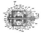
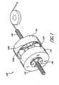
- FIG. 1is a partial perspective view of the transmission of the present invention.
- FIG. 2is a partial exploded view of the transmission of FIG. 1 .
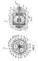
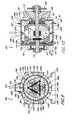
- FIG. 3is an end cutaway elevational view of the transmission of FIG. 1 .
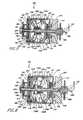
- FIG. 4is a cutaway side elevational view of the transmission of FIG. 1 .
- FIGS. 5 and 6are cutaway side elevational views of the transmission of FIG. 1 illustrating the transmission of FIG. 1 shifted into different positions.
- FIG. 7is an end cutaway view of an alternative embodiment of the transmission of the invention wherein the transmission shifts automatically.
- FIG. 8is a side elevational view of the transmission of FIG. 7 .
- FIG. 9is an end cutaway view of an alternative embodiment of the transmission of the invention wherein the transmission includes a stationary hub shell.
- FIG. 10is a cutaway side elevational view of the transmission of FIG. 9 .
- FIG. 11is a cutaway side elevational view of an alternative embodiment of the transmission of FIG. 1 wherein the transmission has two thrust bearings.
- FIG. 12is a cutaway side elevational view of an alternative embodiment of the invention wherein a first and second one way rotatable driver provides an input torque to the transmission.
- FIG. 13is a schematic cutaway end elevational view of another alternative embodiment of the transmission of the invention.
- FIG. 14is a schematic cutaway front elevational view of the transmission of FIG. 13 .
- FIG. 15is a schematic end view of a housing for the transmission of FIGS. 13 and 14.
- FIG. 16is a schematic cutaway front elevational view of another alternative embodiment of the transmission of the invention.
- FIG. 17is a side elevational view of an alternative embodiment of a support member.
- the present inventionincludes a continuously variable transmission that may be employed in connection with any type of machine that is in need of a transmission.
- the transmissionmay be used in (i) a motorized vehicle such as an automobile, motorcycle, or watercraft, (ii) a non-motorized vehicle such as a bicycle, tricycle, scooter, exercise equipment or (iii) industrial power equipment, such as a drill press.
- FIGS. 1 through 4disclose one embodiment of the present invention.
- FIG. 1is a partial perspective view of a transmission 100 .
- FIG. 2is an exploded view of the transmission 100 of FIG. 1 .
- FIG. 3shows a partial cross sectional end view of the transmission 100 .
- FIG. 4shows a cutaway side elevational view of the transmission 100 .
- a hollow main shaft 102is affixed to a frame of a machine (not shown).
- the shaft 102may be threaded at each end to allow a fastener (not shown) to be used to secure the transmission 100 on the main shaft 102 and/or to attach the main shaft 102 to a machine.
- a rotatable driver 401(FIG. 4) comprising a sprocket or a pulley is rotatably affixed to the main shaft 102 , so as to provide an input torque to the transmission 100 .
- a drive sleeve 104is coaxially coupled to the rotatable driver 401 (FIG. 4) and rotatably disposed over the main shaft 102 .
- a surface 106 (FIG. 2) of the drive sleeve 104 opposite the rotatable driver 401 (FIG. 4 ),can include a plurality of shallow grooves 108 .
- a first roller cage assembly 110is coaxially coupled to the drive sleeve 106 opposite the rotatable driver 401 and also rotatably disposed over the main shaft 102 .
- the first roller cage assembly 110has a plurality of cylindrical rollers 112 radially arranged about a midpoint of the roller cage assembly 110 .
- Each of the cylindrical rollers 112are rotatably mounted on the first roller cage assembly 110 such that each of the rollers may rotate about its lengthwise axis.
- a one-to-one correlationexists between each of the shallow grooves 108 and each of the cylindrical rollers 112 .
- the cylindrical rollers 112may be replaced with rollers of an alternative geometric shape, such as with spherical rollers.
- a tension inducer 118(FIG. 2 ), such as a spring, is rotatably disposed over the main shaft 102 and frictionally coaxially coupled to the first roller cage assembly 110 opposite to the drive sleeve 104 .
- a rotatable driving member 120is rotatably affixed to the main shaft 102 and coaxially coupled to a side of the first roller cage assembly 110 opposite the drive sleeve 104 .
- a surface 107 (FIG. 4) of the rotatable driving member 120 opposed to the drive sleeve 104includes a plurality of shallow grooves 109 (FIG. 4 ).
- Relative rotation of the roller cage 110 with respect to the drive sleeve 104causes the cylindrical rollers 112 to roll on the shallow grooves 108 , 109 and move the shallow grooves 108 , 109 toward or away from each other along the axis of the main shaft 102 .
- a plurality of spherical power adjusters 122 A, 122 B, 122 Care in frictional contact with a side of the rotatable driving member 120 opposite the roller cage assembly 110 .
- the power adjusters 122 A, 122 B, 122 Care spheres made of hardened steel; however, the power adjusters 122 A, 122 B, 122 C may alternatively include other shapes and be manufactured from other materials.
- a plurality of spindles 130 A, 130 B, 130 Crespectively extend through multiple passages 128 A, 128 B, 128 C (FIG. 2) in the power adjusters 122 A, 122 B, 122 C.
- Radial bearings(not shown) may be disposed over each of the spindles 130 A, 130 B, 130 C (FIG. 2) to facilitate the rotation of the power adjusters 122 A, 122 B, 122 C.
- a plurality of pivot supports 134 A, 134 B, 134 Crespectively hold the spindles 130 A, 130 B, 130 C (FIG. 2 ).
- the support 134 Aincludes two legs 135 A and 137 A for connection to a ratio changer 166 which is discussed in further detail below.
- the support 134 Bincludes two legs 135 B and 137 B
- the pivot support 134 Cincludes two legs 135 C and 137 C.
- the pivot supports 134 A, 134 B, 134 Crespectively include pivot rings 136 A, 136 B, 136 C.
- the pivot ring 136 Ahas four apertures 138 A, 140 A, 142 A, 144 A (FIG. 2 ).
- the pivot support 134 Bhas four apertures 138 B, 140 B, 142 B, and 144 B
- the pivot support 134 Chas four apertures 138 C, 140 C, 142 C, and 144 C (FIG. 2 ).
- the apertures 138 A, 138 B, 138 Care respectively located opposite to the apertures 140 A, 140 B, 140 C on the pivot rings 136 A, 136 B, and 136 C. Together, the apertures 138 A, 138 B, 138 C, and the apertures 140 A, 140 B, 140 C are respectively configured to receive the spindles 130 A, 130 B, 130 C (FIG. 2 ).
- the apertures 142 A, 142 B, 142 Care respectively located opposite to the apertures 144 A, 144 B, 144 C (FIG. 2) on the pivot rings 136 A, 136 B, 136 C. Together, the apertures 142 A, 142 B, 142 C and the apertures 144 A, 144 B, 144 C are configured to receive multiple immobilizers 150 A, 150 B, 150 C (FIG. 2 ).
- the immobilizers 150 A, 150 B, 150 Care each cylindrical rigid rods, slightly angled at each end. A central portion of each of the immobilizers 150 A, 150 B, 150 C are affixed to one of multiple legs 153 (FIG. 2) of a stationary support 152 (FIG. 2 ). The stationary support 152 is fixedly attached to the main shaft 102 .
- a support member 154is slidingly and rotatably disposed over the main shaft 102 proximate to a side of the stationary support 152 (FIG. 2) which is opposite to the rotatable driving member 120 .
- the support member 154is in frictional contact with each of the power adjusters 122 A, 122 B, 122 C.
- the support member 154is a cylindrical ring having a substantially uniform outer circumference from an end cross-sectional view.
- the support member 154is a cylindrical ring having a first and second flange (not shown) which respectively extend radially outwardly from a first and second end of the support member 154 so as to prevent the power adjusters 122 A, 122 B, 122 C from disengaging from the support member 154 .
- the support member 154is a cylindrical ring having a nominally concavical outer surface (FIG. 17 ).
- the support member 154may contact and rotate upon the main shaft 102 , or may be suspended over the main shaft 102 without substantially contacting it due to the centering pressures applied by the power adjusters 122 A, 122 B, 122 C.
- a shifting member 160such as an inflexible rod, is slidingly engaged to an inner passage of the main shaft 102 .
- Two extensions 162 , 164perpendicularly extend from the shifting member 160 through an opening 165 in the main shaft 102 .
- a first end 161 of the shifting member 160 proximate to the drive side of the transmission 100is connected to a linkage 163 , such as a cable.
- the linkage 163is connected at an end opposite to the main shaft 102 to a shifting actuator (not shown).
- a tension member 202such as a spring, is connected to a second end of the shifting member 160 by a fastener 204 .
- the extensions 162 , 164connect to the ratio changer 166 .
- the ratio changer 166includes a planar platform 168 and a plurality of legs 171 A, 171 B, 171 C which perpendicularly extend from a surface of the platform 168 proximate to the support member 154 .
- the leg 171 Aincludes two linkage pins 172 A, 173 A.
- the leg 171 Bincludes two linkage pins 172 B and 173 B
- the leg 171 Cincludes two linkage pins 172 C and 173 C.
- the linkage pins 172 A, 172 B, 172 C, and the linkage pins 173 A, 173 B, 173 Care used to couple the ratio changer 166 to each of the pivot supports 134 A, 134 B, and 134 C.
- the linkage pin 172 Aengages an end of the leg 137 A of the support 134 A opposite the pivot ring 136 A
- the linkage pin 172 Bengages an end of the leg 135 A opposite the pivot ring 136 A
- the linkage pin 173 Bengages an end of the leg 137 B opposite the pivot ring 136 B
- the linkage pin 172 Cengages an end of the leg 135 B opposite the pivot ring 136 B.
- the linkage pin 173 Cengages an end of the leg 137 C opposite the pivot ring 136 C
- the linkage pin 173 Aengages an end of the leg 137 B opposite the pivot ring 136 C.
- the transmission 100 of the inventionmay be configured with fewer (e.g., 2) or more (e.g., 4, 5, 6 or more) power adjusters. Further, the number of legs on the ratio changer 166 , the number of legs on the stationary support 152 , the number of immobilizers, the number of pivot supports in the transmission may all be correspondingly adjusted according to the number of power adjusters that are employed.
- a rotatable driven member 170is rotatably engaged to the main shaft 102 proximate to the ratio changer 166 (FIG. 2 ).
- the rotatable driven member 170is in frictional contact with each of the power adjusters 122 A, 122 B, 122 C.
- the rotatable driven member 170is in frictional coaxial contact with a second tension inducer 178 (FIG. 2 ), such as a spring, and a second roller cage assembly 180 that is similar in design to the roller cage assembly 110 .
- the second tension inducer 178 (FIG. 2) and the second roller cage assembly 180are rotatably disposed over the main shaft 102 .
- a hub driver 186(FIG. 4) is rotatably disposed over the main shaft 102 and coaxially engaged to a side of the second roller cage assembly 180 opposite the rotatable driven member 170 .
- the hub driver 186(FIG. 4) may be affixed to a hub shell 302 (FIGS. 3 and 4) using any traditional gearing mechanism.
- the hub driver 186extends proximate to the hub shell 302 and is connected to a one way rotatable driver 300 , such as a one way roller clutch.
- the one way rotatable driver 300(FIGS. 3 and 4) is rotatably coupled to the hub shell 302 (FIGS. 3 and 4 ).
- the power adjusters 122 A, 122 B, 122 Care suspended in tight three-point frictional contact with the drive member 120 , the support member 154 , and the driven member 170 .
- the hub shell 302(FIGS. 3 and 4) has a plurality of holes 304 (FIG. 3) which provide a means for attaching the hub shell 302 to a wheel, propeller or other propulsion means.
- the hub shell 302is supported and is free to rotate on the main shaft 102 by means of hub bearings 410 (FIG. 4) which fit into slots in the hub driver 186 .
- a washer 412(FIG. 4) is affixed to the main shaft 102 proximate to a side of the hub driver 186 opposite the second roller cage assembly 180 to facilitate the rotation of the hub bearings 410 (FIG. 4 ).
- FIGS. 5 and 6are a cutaway side elevational views of the transmission of FIG. 1 illustrating the transmission of FIG. 1 in two different shifted positions. With reference to FIGS. 5 and 6, a method of shifting the transmission 100 is disclosed below.
- the drive sleeve 104Upon an input force, the drive sleeve 104 begins to rotate in a clockwise direction. (It should be noted that the transmission 100 is also designed to be driven in a counter-clockwise direction.) At the beginning of the rotation of the drive sleeve 104 , nominal axial pressure is supplied by the tension inducers 118 , 178 (FIG. 2) to ensure that the rotatable driving member 120 , the rotatable driven member 170 , and the support member 154 are in tractive contact with the power adjusters 122 A, 122 B, 122 C.
- the rotation of the drive sleeve 104 in a clockwise directionengages the first roller cage assembly 110 to rotate in a similar direction.
- the rollers 112remain centered between the shallow grooves 108 , 109 of the rotatable driving member 120 and the drive sleeve 104 .
- the rollers 112ride up the sloping sides of the grooves 108 and force the drive sleeve 104 and the rotatable driving member 120 farther apart.
- the same actionoccurs on the opposite end of the transmission 100 wherein the rotatable driven member 170 engages the hub driver 186 though the second roller cage assembly 180 .
- first roller cage assembly 110 and second roller cage assembly 180compress the rotatable driving member 120 and the rotatable driven member 170 together against the power adjusters 122 A, 122 B, 122 C, which increases the frictional contact of the power adjusters 122 A, 122 B, 122 C against the support member 154 , the drive member 120 , and the driven member 170 .
- the roller cage assembly 110frictionally rotates the power adjusters 122 A, 122 B, 122 C.
- the clockwise rotation of the power adjusters 122 A, 122 B, 122 Ccauses a clockwise rotation of the rotatable driven member 170 .
- the clockwise rotation of the rotatable driven member 170engages the second roller cage assembly 180 to rotate in a clockwise direction.
- the clockwise rotation of the second roller cage assembly 180engages the hub driver 186 (FIG. 4) to drive in a clockwise direction.
- the clockwise rotation of the hub driver 186causes the one way rotatable driver 300 to rotate clockwise.
- the one way rotatable driver 300then drives the hub shell 302 (FIGS. 3 and 4) to rotate in a clockwise direction.
- the shifting member 160is used to modify the axis of a rotation for the power adjusters 122 A, 122 B, 122 C.
- the shifting actuatorslides the shifting member 160 in a first direction 500 (FIG. 5 ).
- a release in tension of the linkage 163 by the shifting actuatorcauses the shifting member 160 to slide in a second and opposite direction 600 (FIG. 6) by the tension member 202 .
- the particular construction of the present transmission 100provides for much easier shifting than prior art traction roller designs.
- the extensions 162 , 164engage the ratio changer 166 to axially move across the main shaft 102 .
- the ratio changer 166pivots the supports 134 A, 134 B, 134 C.
- the pivoting of the supports 134 A, 134 B, 134 Ctilts the ball spindles 130 A, 130 B, 130 C and changes the axis of rotation of each of the power adjusters 122 A, 122 B, and 122 C.
- the axis of rotation of each of the power adjusters 122 A, 122 B, 122 Cis modified such that the rotatable driving member 120 contacts a surface of power adjuster, 120 A, 120 B, 120 C closer to the axis of rotation of the power adjusters 120 A, 120 B, 120 C.
- the rotatable driven member 170contacts the power adjuster at a point on a surface of the each of the power adjusters 120 A, 120 B, 120 C further away from the axis of rotation of the power adjusters 120 A, 120 B, 120 C.
- the adjustment of the axis of rotation for the power adjusters 122 A, 122 B, 122 Cincreases an output angular velocity for the transmission 100 because for every revolution of the rotatable driving member 120 , the rotatable driven member 170 rotates more than once.
- the transmission 100 of the inventionis shown in a position which causes a decrease in the output angular velocity for the transmission 100 .
- the shifting member 160is directed in the direction 600 , opposite the first direction 500 , the axis of rotation of each of the power adjusters 122 A, 122 B, 122 C is modified such that the rotatable driven member 170 contacts a surface of each of the power adjusters 122 A, 122 B, 122 C closer to the axis of rotation of each of the power adjusters 122 A, 122 B, 122 C.
- the rotatable driving member 120contacts each of the power adjusters 122 A, 122 B, 122 C at a point on a surface of each of the power adjusters 122 A, 122 B, 122 C further away from the axis of rotation of each of the power adjusters 122 A, 122 B, 122 C.
- the adjustment of the axis of rotation for the power adjusters 122 A, 122 B, 122 Cdecreases an output angular velocity for the transmission 100 because for every revolution of the rotatable driving member 120 , the rotatable driven member 170 rotates less than once.
- FIGS. 7 and 8illustrate an automatic transmission 700 of the present invention. For purposes of simplicity of description, only the differences between the transmission 100 of FIGS. 1-6 and the automatic transmission 700 are described.
- FIG. 7is a partial end elevational view of the transmission 700
- FIG. 8is partial side elevational view of the transmission 700 .
- a plurality of tension members 702 A, 702 B, 702 Cwhich may each be a spring, interconnect each of the pivot rings 136 A, 136 B, 136 C.
- the tension member 702 Ais connected at a first end to the pivot ring 136 A and at a second end opposite the first end to the pivot ring 136 B.
- the tension member 702 Bis connected at a first end to the pivot ring 136 B proximate to the aperture 138 B and at a second end opposite the first end to the pivot ring 136 C proximate to the aperture 138 C.
- the tension member 702 Cis connected at a first end to the pivot ring 136 C proximate to the aperture 138 C and at a second end opposite the first end to the pivot ring 136 A proximate to the aperture 138 A.
- the transmission 700also includes flexible extension members 708 A, 708 B, 708 C respectively connected at a first end to the pivot rings 136 A, 136 B, 136 C.
- the transmission 700also includes a first annular bearing 806 and a second annular bearing 816 to assist in the shifting of the transmission 700 .
- the first annular bearing 806is slidingly attached to the hub shell 302 such that first the annular bearing 806 can further be directed toward the rotatable driving member 120 or the rotatable driven member 170 .
- the second annular bearing 816also is configured to be slid toward either the rotatable driving member 120 or the rotatable driven member 170 ; however, the second annular bearing 816 is not rotatable about the main shaft 102 , unlike the first annular bearing 806 .
- the first annular bearing 806 and the second annular bearing 816supports multiple bearing balls 808 .
- a second end of each the extension members 708 A, 708 B, 708 Cconnects to the second annular bearing 816 (FIG. 8 ).
- extension members 718 A, 718 B, 718 Crespectively connect the first annular bearing 806 to multiple weights 720 A, 720 B, 720 C.
- a plurality of pulleys 822may be used to route the extension members 718 A, 718 B, 718 C from the second annular bearing 816 to the weights 720 A, 720 B, 720 C, and route the extension members 708 A, 708 B, 708 C to the first annular bearing 806 .
- a clockwise input torquecauses clockwise rotation of the drive sleeve 104 , the first roller cage assembly 110 , and the rotatable driving member 120 .
- the rotatable driving member 120engages the power adjusters 122 A, 122 B, 122 C to rotate, and thereby drives the rotatable driven member 170 .
- the rotation of the rotatable driven member 170drives the second roller cage assembly 180 and produces an output torque.
- the ratio of rotation between the rotatable driving member 120 and the rotatable driven member 170is adjusted automatically by a centrifugal outward movement of the weights 720 A, 720 B, 720 C.
- the extensions 718 A, 718 B, 718 Cpull the first annular bearing 806 toward the rotatable driving member 120 .
- the movement of the first annular bearing 806 toward the rotatable driving member 120similarly causes the movement of the bearings 808 and the second annular bearing 816 toward the rotatable driving member 120 .
- the movement of the first annular bearing 806 toward the rotatable driving member 120causes the extension members 708 A, 708 B, 708 C to respectively pivot the pivot rings 306 A, 306 B, 306 C and adjust the axis of rotation of each of the power adjusters 122 A, 122 B, 122 C.
- the rotatable driven member 170contacts a surface of power adjusters 120 A, 120 B, 120 C closer to the axis of rotation of each of the power adjuster 122 A, 122 B, 122 C.
- the rotatable driving member 120contacts the power adjusters 122 A, 122 B, 122 C at a point on a surface of the each of the power adjusters 122 A, 122 B, 122 C further away from the axis of rotation of the power adjusters 122 A, 122 B, 122 C.
- the adjustment of the axis of rotation for the power adjusters 122 A, 122 B, 122 Cdecreases an output angular velocity for the transmission 100 because for every revolution of the rotatable driving member 120 , the rotatable driven member 170 rotates less than once.
- the compression members 702 A, 702 B, 702 Cadjust the axis of rotation of the power adjusters 122 A, 122 B, 122 C to provide to a lower output angular velocity in comparison to the input angular velocity.
- FIGS. 9 and 10illustrate an alternative embodiment of the invention. For purposes of simplicity of description, only the differences between the transmission 100 of FIG. 1 and a transmission 900 of FIGS. 9 and 10 are described.
- FIG. 9is a partial end elevational view of the transmission 900
- FIG. 10is partial side elevational view of the transmission 900 .
- the transmission 900includes flexible extension members 908 A, 908 B, 908 C respectively connected at a first end to the pivot rings 136 A, 136 B, 136 C.
- a second end of the extension members 908 A, 908 B, 908 Cconnects to a synchronization member 912 .
- each of the extension members 908 A, 908 B, 908 Care slidingly engaged to a plurality of pulleys 916 (FIG. 9) which are affixed to the hub shell 302 . It is noted that the number and location of the each of the pulleys 916 (FIG. 9) may be varied.
- a different pulley configurationmay be used to route the extension members 908 A, 908 B, 908 C depending on the selected frame of the machine or vehicle that employs the transmission 900 .
- the pulleys 916 and extension members 908 A, 908 B, 908 Cmay be located inside the hub shell 302 .
- the hub shell 302 of the transmission 900is non-rotational. Further, the hub shell 302 includes a plurality of apertures (not shown) which are used to guide the extension members 908 A, 908 B, 908 C to the synchronization member 912 .
- the shifting assembly of the transmission 100 of FIG. 2may be eliminated, including the main shaft 102 (FIG. 2 ), the tension member 202 (FIG. 2 ), the extensions 162 , 164 (FIG. 2) and the shifting actuator (not shown).
- an input torquecauses a clockwise rotation of the drive sleeve 104 , the first roller cage assembly 110 , and the rotatable driving member 120 .
- the rotatable driving member 120engages the power adjusters 122 A, 122 B, 122 to rotate, and thereby drive the rotatable driven member 170 .
- the rotation of the rotatable driven member 170drives the second roller cage assembly 180 and produces an output torque.
- the ratio of rotation between the rotatable driving member 120 and the rotatable driven member 170is adjusted by the manipulation of the synchronization member 912 .
- the extension members 908 A, 908 B, 908 Crespectively pivot the pivot rings 136 A, 136 B, 136 C such that the axis of rotation of each of the power adjusters 122 A, 122 B, and 122 C is similarly pivoted.
- each of the power adjusters 122 A, 122 B, 122 Cis modified such that the rotatable driving member 120 contacts a surface of power adjusters 122 A, 122 B, 122 C further away from the axis of rotation of each of the power adjusters 122 A, 122 B, 122 C.
- the rotatable driven member 170contacts the power adjusters 122 A, 122 B, 122 C at a point on a surface of the each of the power adjusters 122 A, 122 B, 122 C closer to the axis of rotation of each of the power adjusters 122 A, 122 B, 122 C.
- the adjustment of the axis of rotation for the power adjusters 122 A, 122 B, 122 Cdecreases an output angular velocity for the transmission 100 because for every revolution of the rotatable driving member 120 , the rotatable driven member 170 rotates less than once.
- the tension members 702 A, 702 B, 702 Ccompress. This compression causes an end of the pivot rings 136 A, 136 B, 136 C proximate to the rotatable driven member 170 to pivot toward the main shaft 102 .
- the pivoting of the pivot rings 136 A, 136 B, 136 Ccauses the axis of rotation of each of the power adjusters 122 A, 122 B, 122 C to be modified such that the rotatable driven member 170 rotates slower than the rotatable driving member 120 .
- FIG. 11illustrates another alternative embodiment of the invention including a transmission 1100 having a first thrust bearing 1106 and a second thrust bearing 1108 .
- the first thrust bearing 1106is rotatably disposed over the main shaft 102 and is positioned between the support member 154 and the extensions 162 , 164 .
- the second thrust bearing 1108is disposed over the main shaft 102 on a side of the support member 154 opposite the first thrust bearing 1106 .
- the transmission 1100may optionally also include a second ratio changer, such as ratio changer 1110 , which is disposed over the main shaft 102 and is axially slidable.
- the ratio changers 166 , 1110slide axially to cause a shift in the transmission 1100
- the ratio changers 166 , 1110also slide the thrust bearings 1106 , 1108 .
- the sliding of the thrust bearings 1106 , 1108forces the support member 154 to slide in unison with the ratio changers 166 , 1110 .
- a small amount of playis provided between the support member 154 and the thrust bearings 1106 , 1008 so that the thrust bearings 1106 , 1108 do not contact the support member 154 except when the transmission 1100 is in the process of shifting.
- FIG. 12illustrates an alternative embodiment of the invention.
- FIG. 12illustrates a transmission 1200 that operates similarly to the embodiment of the invention disclosed in FIG. 10; however, the transmission 1200 of FIG. 12 includes two rotatable drivers 1204 , 1206 and a rotatable driving shaft 1212 .
- the rotatable driving shaft 1212is fixedly attached to the drive sleeve 104 .
- the first rotatable driver 1204includes a one way clutch 1208 that is configured to rotate the rotatable driving shaft 1212 upon the rotation of the rotatable driver in a first direction.
- the second rotatable driver 1206includes a one way clutch 1210 .
- the second rotatable driver 1206is configured to engage the drive sleeve 104 upon the rotation of the second rotatable driver 1206 in a second direction, which is opposite to the activation direction of the first rotatable driver 1204 .
- the second rotatable driver 1206is fixedly attached to the drive sleeve 104 .
- FIG. 13schematically illustrates another alternative embodiment of the invention having a transmission 1300 that is configured to shift automatically.
- Three pulleys 1306 , 1308 , 1310are respectively connected to the pivot rings 136 A, 136 B, and 136 C.
- a cable 1312is guided around the pulley 1306 and connects at a first end to the main shaft 102 and connects at a second end to an annular ring (not shown), similar to the annular ring 816 of FIG. 8 .
- a cable 1314is guided around the pulley 1308 and connects to the main shaft 102 at a first end and connects at a second end to the annular ring (not shown)
- a cable 1316is guided around the pulley 1310 and connects at a first end to the main shaft 102 and connects at a second end to the annular ring (not shown).
- FIG. 14schematically illustrates the transmission 1300 of FIG. 13 from a front end.
- a plurality of tension members 1404 , 1406 , 1408interconnect each of the pivot rings 136 A, 136 B, and 136 C.
- the tension member 1404connects at a first end to the pivot ring 136 A and connects at a second end opposite the first end to the pivot ring 136 B.
- the tension member 1406connects at a first end to the pivot ring 136 B and connects at a second end opposite the first end at the pivot ring 136 C.
- the tension member 1408connects at a first end to the pivot ring 136 A and connects at a second end opposite the first end at the pivot ring 136 C.
- FIG. 15schematically illustrates a housing 1500 for the transmission 1300 of FIGS. 13 and 14.
- the housing 1500includes three hollow guide tubes 1504 , 1506 , and 1508 .
- Each of the hollow guide tubes 1504 , 1506 , 1508connect at a first end to a hub shell 1512 that holds the transmission 1300 and at a second end opposite the first end to a transmission wheel 1514 .
- Three tension members 1516 , 1518 , 1520are respectively disposed within the guide tubes 1504 , 1506 , 1508 and are connected at a first end to the transmission wheel 1514 .
- a second end of the tension members 1516 , 1518 , 1520 opposite the transmission wheel 1514are respectively connected with spherical weights 1526 , 1528 , 1530 .
- the weights 1526 , 1528 , 1530may be adapted to other geometric shapes.
- Multiple linkage members 1532 , 1534 , 1536respectively extend from the weights 1526 , 1528 , 1530 to an annular member (not shown), such as the annular member 806 of FIG. 8 .
- the rotation of the hub shell 1512causes the rotation of the hollow guide tubes 1504 , 1506 , 1508 .
- the weights 1526 , 1528 , 1530extend outwardly toward the transmission wheel 1514 .
- the outward movement of the weights 1526 , 1528 , 1530causes a shifting of the axis of rotation of the power adjusters 122 A, 122 B, 122 C of FIGS. 13 and 14.
- FIG. 16is another alternative embodiment of the invention.
- FIG. 16is a schematic illustration of a manual version of the transmission 1300 shown in FIGS. 13 and 14. For purposes of simplicity of description, only the differences between the transmission 1600 of FIG. 16 and the transmission 1300 of FIGS. 13 and 14 are described.
- the transmission 1600includes a flexible cable 1602 that connects at a first end to a shifting actuator (not shown).
- the cable 1602extends from the shifting actuator (not shown), through the central passageway of the main shaft 102 and then extends through an aperture (not shown) on the main shaft 102 . From the aperture (not shown) the cable 1602 extends around the pulley 1308 . From the pulley 1308 , the cable is guided around the pulley 1306 . From the pulley 1306 , the cable extends to the pulley 1308 . Finally, from the pulley 1308 , the cable 1602 connects to the main shaft 102 .
- the cable 1602pulls on the pulleys 1304 , 1306 , 1308 thereby causing a shift in the axis of rotation of each of the power adjusters 122 A, 122 B, 122 C.
- the shifting actuatorreleases the cable 1602
- the tension members 1404 , 1406 , 1408cause each of the axis of rotation of the power adjusters 122 A, 122 B, 122 C to shift in a second and opposite direction.
- the present inventionprovides a novel transmission which provides a continuously variable input/output angular velocity ratio offering up to a 900% range of input/output angular velocity. Further, the transmission can be actuated either manually or automatically.
- the transmission of the inventionprovides a simple design which requires a minimal number of parts to implement, and is therefore simple to manufacture, compact, light and produces very little friction.
- the transmissioneliminates duplicate, overlapping, or unusable gears which are found in geared transmissions.
- the transmissioneliminates the need for clutches which are traditionally used for changing gears.
- the transmissioncan save energy or gasoline by providing an ideal input to output angular speed ratio.
Landscapes
- Engineering & Computer Science (AREA)
- Mechanical Engineering (AREA)
- General Engineering & Computer Science (AREA)
- Chemical & Material Sciences (AREA)
- Combustion & Propulsion (AREA)
- Transportation (AREA)
- Friction Gearing (AREA)
- Transition And Organic Metals Composition Catalysts For Addition Polymerization (AREA)
- Liquid Crystal Substances (AREA)
- Valve-Gear Or Valve Arrangements (AREA)
- External Artificial Organs (AREA)
Abstract
Description
Claims (14)
Priority Applications (28)
| Application Number | Priority Date | Filing Date | Title |
|---|---|---|---|
| US10/016,116US6676559B2 (en) | 1997-09-02 | 2001-10-30 | Continuously variable transmission |
| US10/418,509US6945903B2 (en) | 1997-09-02 | 2003-04-16 | Continuously variable transmission |
| US11/006,216US7044884B2 (en) | 1997-09-02 | 2004-12-06 | Continuously variable transmission |
| US11/005,936US7074155B2 (en) | 1997-09-02 | 2004-12-06 | Continuously variable transmission |
| US11/006,317US7112158B2 (en) | 1997-09-02 | 2004-12-06 | Continuously variable transmission |
| US11/006,217US7160222B2 (en) | 1997-09-02 | 2004-12-06 | Continuously variable transmission |
| US11/006,114US7063640B2 (en) | 1997-09-02 | 2004-12-06 | Continuously variable transmission |
| US11/006,235US7140999B2 (en) | 1997-09-02 | 2004-12-06 | Continuously variable transmission |
| US11/006,213US7074154B2 (en) | 1998-08-12 | 2004-12-06 | Continuously variable transmission |
| US11/006,348US7175564B2 (en) | 1997-09-02 | 2004-12-06 | Continuously variable transmission |
| US11/006,212US7156770B2 (en) | 1997-09-02 | 2004-12-06 | Continuously variable transmission |
| US11/006,409US7217219B2 (en) | 1997-09-02 | 2004-12-06 | Continuously variable transmission |
| US11/005,935US7011601B2 (en) | 1997-09-02 | 2004-12-06 | Continuously variable transmission |
| US11/005,869US7163485B2 (en) | 1997-09-02 | 2004-12-06 | Continuously variable transmission |
| US11/005,673US7014591B2 (en) | 1997-09-02 | 2004-12-06 | Continuously variable transmission |
| US11/006,214US7074007B2 (en) | 1997-09-02 | 2004-12-06 | Continuously variable transmission |
| US11/330,425USRE41892E1 (en) | 1997-09-02 | 2006-01-11 | Continuously variable transmission |
| US11/694,049US7402122B2 (en) | 1997-09-02 | 2007-03-30 | Continuously variable transmission |
| US11/694,145US7410443B2 (en) | 1997-09-02 | 2007-03-30 | Continuously variable transmission |
| US11/694,044US7393303B2 (en) | 1997-09-02 | 2007-03-30 | Continuously variable transmission |
| US11/694,492US7419451B2 (en) | 1997-09-02 | 2007-03-30 | Continuously variable transmission |
| US11/693,998US7393302B2 (en) | 1997-09-02 | 2007-03-30 | Continuously variable transmission |
| US11/694,016US7320660B2 (en) | 1997-09-02 | 2007-03-30 | Continuously variable transmission |
| US11/694,119US7384370B2 (en) | 1997-09-02 | 2007-03-30 | Continuously variable transmission |
| US11/694,066US7427253B2 (en) | 1997-09-02 | 2007-03-30 | Continuously variable transmission |
| US11/694,107US7422541B2 (en) | 1997-09-02 | 2007-03-30 | Continuously variable transmission |
| US12/100,305US7727107B2 (en) | 1997-09-02 | 2008-04-09 | Continuously variable transmission |
| US12/360,006US7837592B2 (en) | 1997-09-02 | 2009-01-26 | Continuously variable transmission |
Applications Claiming Priority (7)
| Application Number | Priority Date | Filing Date | Title |
|---|---|---|---|
| US5604597P | 1997-09-02 | 1997-09-02 | |
| US6286097P | 1997-10-16 | 1997-10-16 | |
| US6262097P | 1997-10-22 | 1997-10-22 | |
| US7004497P | 1997-12-30 | 1997-12-30 | |
| US09/133,284US6241636B1 (en) | 1997-09-02 | 1998-08-12 | Continuously variable transmission |
| US09/823,620US6322475B2 (en) | 1997-09-02 | 2001-03-30 | Continuously variable transmission |
| US10/016,116US6676559B2 (en) | 1997-09-02 | 2001-10-30 | Continuously variable transmission |
Related Parent Applications (3)
| Application Number | Title | Priority Date | Filing Date |
|---|---|---|---|
| US09/695,757ContinuationUS6419608B1 (en) | 1997-09-02 | 2000-10-24 | Continuously variable transmission |
| US09/823,620ContinuationUS6322475B2 (en) | 1997-09-02 | 2001-03-30 | Continuously variable transmission |
| US09/823,620Continuation-In-PartUS6322475B2 (en) | 1997-09-02 | 2001-03-30 | Continuously variable transmission |
Related Child Applications (6)
| Application Number | Title | Priority Date | Filing Date |
|---|---|---|---|
| US09/695,757Continuation-In-PartUS6419608B1 (en) | 1997-09-02 | 2000-10-24 | Continuously variable transmission |
| US09/823,620Continuation-In-PartUS6322475B2 (en) | 1997-09-02 | 2001-03-30 | Continuously variable transmission |
| US10/141,652Continuation-In-PartUS6551210B2 (en) | 1997-09-02 | 2002-05-07 | Continuously variable transmission |
| US10/418,509Continuation-In-PartUS6945903B2 (en) | 1997-09-02 | 2003-04-16 | Continuously variable transmission |
| US10/418,509ContinuationUS6945903B2 (en) | 1997-09-02 | 2003-04-16 | Continuously variable transmission |
| US11/330,425ReissueUSRE41892E1 (en) | 1997-09-02 | 2006-01-11 | Continuously variable transmission |
Publications (2)
| Publication Number | Publication Date |
|---|---|
| US20020042322A1 US20020042322A1 (en) | 2002-04-11 |
| US6676559B2true US6676559B2 (en) | 2004-01-13 |
Family
ID=27370341
Family Applications (3)
| Application Number | Title | Priority Date | Filing Date |
|---|---|---|---|
| US09/133,284Expired - LifetimeUS6241636B1 (en) | 1997-09-02 | 1998-08-12 | Continuously variable transmission |
| US09/823,620Expired - Fee RelatedUS6322475B2 (en) | 1997-09-02 | 2001-03-30 | Continuously variable transmission |
| US10/016,116CeasedUS6676559B2 (en) | 1997-09-02 | 2001-10-30 | Continuously variable transmission |
Family Applications Before (2)
| Application Number | Title | Priority Date | Filing Date |
|---|---|---|---|
| US09/133,284Expired - LifetimeUS6241636B1 (en) | 1997-09-02 | 1998-08-12 | Continuously variable transmission |
| US09/823,620Expired - Fee RelatedUS6322475B2 (en) | 1997-09-02 | 2001-03-30 | Continuously variable transmission |
Country Status (12)
| Country | Link |
|---|---|
| US (3) | US6241636B1 (en) |
| EP (1) | EP1023545B1 (en) |
| JP (3) | JP4061452B2 (en) |
| KR (2) | KR100584022B1 (en) |
| CN (1) | CN1146693C (en) |
| AT (1) | ATE385552T1 (en) |
| AU (1) | AU751503B2 (en) |
| CA (2) | CA2731528C (en) |
| DE (1) | DE69839094T2 (en) |
| DK (1) | DK1023545T3 (en) |
| ES (1) | ES2301213T3 (en) |
| WO (1) | WO1999020918A1 (en) |
Cited By (48)
| Publication number | Priority date | Publication date | Assignee | Title |
|---|---|---|---|---|
| US20040171452A1 (en)* | 2003-02-28 | 2004-09-02 | Miller Donald C. | Continuously variable transmission |
| US20040224808A1 (en)* | 2003-08-11 | 2004-11-11 | Miller Donald C. | Continuously variable planetary gear set |
| US20050073127A1 (en)* | 2000-10-24 | 2005-04-07 | Miller Donald C. | Continuously variable transmission |
| US20050079948A1 (en)* | 2001-04-26 | 2005-04-14 | Miller Donald C. | Continuously variable transmission |
| US20060022429A1 (en)* | 1998-03-02 | 2006-02-02 | Anthony S. Ellsworth | Bicycle suspension apparatus and related method |
| US20060084549A1 (en)* | 2004-10-05 | 2006-04-20 | Smithson Robert A | Continuously variable transmission |
| US20070049450A1 (en)* | 2005-08-24 | 2007-03-01 | Miller Donald C | Continuously variable transmission |
| US7214159B2 (en) | 2003-08-11 | 2007-05-08 | Fallbrook Technologies Inc. | Continuously variable planetary gear set |
| US20070142161A1 (en)* | 2005-10-28 | 2007-06-21 | Miller Donald C | Electromotive drives |
| US20070155567A1 (en)* | 2005-11-22 | 2007-07-05 | Fallbrook Technologies Inc. | Continuously variable transmission |
| US20070197337A1 (en)* | 2004-07-21 | 2007-08-23 | Fallbrook Technologies Inc. | Rolling traction planetary drive |
| US20070295301A1 (en)* | 2006-04-29 | 2007-12-27 | Klassen James B | Energy transfer machine with inner rotor |
| US20080073137A1 (en)* | 2006-05-11 | 2008-03-27 | Fallbrook Technologies Inc. | Continuously variable drivetrain |
| US20080236319A1 (en)* | 2005-12-09 | 2008-10-02 | Fallbrook Technologies Inc. | Continuously variable transmission |
| US20090082169A1 (en)* | 2005-12-30 | 2009-03-26 | Fallbrook Technologies Inc. | Continuously variable gear transmission |
| US20090114058A1 (en)* | 2007-11-07 | 2009-05-07 | Fallbrook Technologies Inc. | Self-centering control rod |
| US20090132135A1 (en)* | 2007-11-16 | 2009-05-21 | Fallbrook Technologies Inc. | Controller for variable transmission |
| US20090221391A1 (en)* | 2008-02-29 | 2009-09-03 | Fallbrook Technologies Inc. | Continuously and/or infinitely variable transmissions and methods therefor |
| US7600963B2 (en) | 2005-08-22 | 2009-10-13 | Viryd Technologies Inc. | Fluid energy converter |
| US20090280949A1 (en)* | 2008-05-07 | 2009-11-12 | Fallbrook Technologies Inc. | Assemblies and methods for clamping force generation |
| US20100056322A1 (en)* | 2008-08-26 | 2010-03-04 | Fallbrook Technologies Inc. | Continuously variable transmission |
| US20100093479A1 (en)* | 2007-02-12 | 2010-04-15 | Fallbrook Technologies Inc. | Continuously variable transmissions and methods therefor |
| US20100131164A1 (en)* | 2007-02-01 | 2010-05-27 | Fallbrook Technologies Inc. | Systems and methods for control of transmission and/or prime mover |
| US20100137094A1 (en)* | 2007-04-24 | 2010-06-03 | Fallbrook Technologies Inc. | Electric traction drives |
| US20100173743A1 (en)* | 2007-06-11 | 2010-07-08 | Fallbrook Technologies Inc. | Continuously variable transmission |
| US20100264620A1 (en)* | 2006-03-14 | 2010-10-21 | Fallbrook Technologies Inc. | Wheelchair |
| US20110088503A1 (en)* | 2006-01-30 | 2011-04-21 | Fallbrook Technologies Inc. | System for manipulating a continuously variable transmission |
| US20110105274A1 (en)* | 2008-06-06 | 2011-05-05 | Charles Lohr | Infinitely variable transmissions, continuously variable transmissions, methods, assemblies, subassemblies, and components therefor |
| US20110172050A1 (en)* | 2008-06-23 | 2011-07-14 | Fallbrook Technologies, Inc. | Continuously variable transmission |
| US20110184614A1 (en)* | 2008-08-05 | 2011-07-28 | Cyril Keilers | Methods for control of transmission and prime mover |
| US20110218072A1 (en)* | 2010-03-03 | 2011-09-08 | Fallbrook Technologies Inc. | Infinitely variable transmissions, continuously variable transmissions, methods, assemblies, subassemblies, and components therefor |
| US8167759B2 (en) | 2008-10-14 | 2012-05-01 | Fallbrook Technologies Inc. | Continuously variable transmission |
| US8313404B2 (en) | 2007-02-16 | 2012-11-20 | Fallbrook Intellectual Property Company Llc | Infinitely variable transmissions, continuously variable transmissions, methods, assemblies, subassemblies, and components therefor |
| US8321097B2 (en) | 2007-12-21 | 2012-11-27 | Fallbrook Intellectual Property Company Llc | Automatic transmissions and methods therefor |
| US8360917B2 (en) | 2009-04-16 | 2013-01-29 | Fallbrook Intellectual Property Company Llc | Continuously variable transmission |
| US8376903B2 (en) | 2006-11-08 | 2013-02-19 | Fallbrook Intellectual Property Company Llc | Clamping force generator |
| US8480529B2 (en) | 2006-06-26 | 2013-07-09 | Fallbrook Intellectual Property Company Llc | Continuously variable transmission |
| US8845485B2 (en) | 2011-04-04 | 2014-09-30 | Fallbrook Intellectual Property Company Llc | Auxiliary power unit having a continuously variable transmission |
| US8888643B2 (en) | 2010-11-10 | 2014-11-18 | Fallbrook Intellectual Property Company Llc | Continuously variable transmission |
| US8900085B2 (en) | 2007-07-05 | 2014-12-02 | Fallbrook Intellectual Property Company Llc | Continuously variable transmission |
| US9611921B2 (en) | 2012-01-23 | 2017-04-04 | Fallbrook Intellectual Property Company Llc | Infinitely variable transmissions, continuously variable transmissions, methods, assemblies, subassemblies, and components therefor |
| US9677650B2 (en) | 2013-04-19 | 2017-06-13 | Fallbrook Intellectual Property Company Llc | Continuously variable transmission |
| US10047861B2 (en) | 2016-01-15 | 2018-08-14 | Fallbrook Intellectual Property Company Llc | Systems and methods for controlling rollback in continuously variable transmissions |
| US10458526B2 (en) | 2016-03-18 | 2019-10-29 | Fallbrook Intellectual Property Company Llc | Continuously variable transmissions, systems and methods |
| US11174922B2 (en) | 2019-02-26 | 2021-11-16 | Fallbrook Intellectual Property Company Llc | Reversible variable drives and systems and methods for control in forward and reverse directions |
| US11215268B2 (en) | 2018-11-06 | 2022-01-04 | Fallbrook Intellectual Property Company Llc | Continuously variable transmissions, synchronous shifting, twin countershafts and methods for control of same |
| US11667351B2 (en) | 2016-05-11 | 2023-06-06 | Fallbrook Intellectual Property Company Llc | Systems and methods for automatic configuration and automatic calibration of continuously variable transmissions and bicycles having continuously variable transmission |
| US12442434B2 (en) | 2024-06-04 | 2025-10-14 | Enviolo B.V. | Reversible variable drives and systems and methods for control in forward and reverse directions |
Families Citing this family (51)
| Publication number | Priority date | Publication date | Assignee | Title |
|---|---|---|---|---|
| US6241636B1 (en) | 1997-09-02 | 2001-06-05 | Motion Technologies, Llc | Continuously variable transmission |
| USRE41892E1 (en) | 1997-09-02 | 2010-10-26 | Fallbrook Technologies Inc. | Continuously variable transmission |
| US6419608B1 (en) | 1999-10-22 | 2002-07-16 | Motion Technologies, Llc | Continuously variable transmission |
| JP3436196B2 (en)* | 1999-09-06 | 2003-08-11 | 株式会社島津製作所 | Two-dimensional array type detector |
| EP1235997B1 (en)* | 1999-11-12 | 2003-12-17 | Motion Technologies, LLC | Continuously variable transmission |
| RU2267671C2 (en)* | 1999-11-12 | 2006-01-10 | Фолбрук Текнолоджис, Инк | Infinitely variable transmission |
| CN1904410A (en)* | 1999-11-12 | 2007-01-31 | 福尔布鲁克科技公司 | Continuously variable transmission |
| AU779051B2 (en)* | 2000-06-28 | 2005-01-06 | P.I.H.A. Pty Ltd | Valve |
| JP2002250421A (en)* | 2000-12-21 | 2002-09-06 | Kayseven Co Ltd | Variable speed change gear |
| US20060181050A1 (en)* | 2005-02-14 | 2006-08-17 | Moreno Jose A | Occupant Propelled Transportation Vehicle |
| CA2599517A1 (en)* | 2005-03-18 | 2006-09-21 | James Klassen | Power transfer device |
| KR100694878B1 (en) | 2005-08-24 | 2007-03-13 | 부산대학교 산학협력단 | Friction Transmission Stepless Gear for Bicycle |
| FR2902073B1 (en)* | 2006-06-09 | 2008-09-26 | Michel Pieroni | AUTOMATIC SPEED CHANGE TRANSMISSION DEVICE FOR BICYCLE |
| US8033953B2 (en)* | 2007-05-01 | 2011-10-11 | John Pawloski | Gearless speed reducer or increaser |
| DK2620672T3 (en) | 2008-10-14 | 2015-08-24 | Fallbrook Ip Co Llc | Continuously variable transmission |
| TWI378192B (en)* | 2008-11-07 | 2012-12-01 | Ind Tech Res Inst | Speed adjusting mechanism for roller traction toroidal continuously variable transmission |
| KR20100055352A (en)* | 2008-11-17 | 2010-05-26 | 변동환 | Continuously variable transmission |
| JP5158216B2 (en) | 2009-02-10 | 2013-03-06 | トヨタ自動車株式会社 | Continuously variable transmission mechanism and transmission using the continuously variable transmission mechanism |
| CN102317649B (en)* | 2009-02-16 | 2015-03-18 | 卞东奂 | Continuously variable transmission |
| EP2424081A4 (en)* | 2009-04-21 | 2013-11-13 | Toyota Motor Co Ltd | ENGINE WITH TRANSMISSION FUNCTION |
| KR101116651B1 (en)* | 2009-08-11 | 2012-03-13 | 김창현 | nonstep transmission |
| US8784261B2 (en) | 2009-12-02 | 2014-07-22 | Toyota Jidosha Kabushiki Kaisha | Continuously variable transmission |
| US8382636B2 (en)* | 2009-12-02 | 2013-02-26 | Toyota Jidosha Kabushiki Kaisha | Continuously variable transmission |
| CN102144113B (en) | 2009-12-02 | 2014-02-05 | 丰田自动车株式会社 | Stepless transmission |
| DE112010005291B4 (en) | 2010-02-22 | 2021-09-23 | Toyota Jidosha Kabushiki Kaisha | Power transmission device |
| CN102265063B (en)* | 2010-03-18 | 2014-04-09 | 丰田自动车株式会社 | Continuously variable transmission |
| EP2653747A4 (en)* | 2011-03-29 | 2014-11-26 | Toyota Motor Co Ltd | TRANSMISSION WITH CONTINUOUS VARIATION |
| JP5626076B2 (en)* | 2011-03-30 | 2014-11-19 | トヨタ自動車株式会社 | Continuously variable transmission and method of assembling continuously variable transmission |
| CN102808909B (en)* | 2011-06-03 | 2015-04-15 | 袁啸宇 | Non-slip type stepless speed change device |
| US20140094339A1 (en)* | 2011-06-10 | 2014-04-03 | Toyota Jidosha Kabushiki Kaisha | Continuously variable transmission |
| JP5522122B2 (en)* | 2011-06-10 | 2014-06-18 | トヨタ自動車株式会社 | Continuously variable transmission |
| CN102951252A (en)* | 2011-08-18 | 2013-03-06 | 王云逸 | Mechanical continuously variable transmission for bicycles |
| US8439151B2 (en) | 2011-09-23 | 2013-05-14 | Trw Automotive U.S. Llc | Apparatus for use in turning steerable vehicle wheels |
| CA2850224A1 (en) | 2011-10-03 | 2013-04-11 | Fallbrook Intellectual Property Company Llc | Refrigeration system having a continuously variable transmission |
| US9057439B2 (en) | 2013-03-14 | 2015-06-16 | Team Industries, Inc. | Infinitely variable transmission with IVT traction ring controlling assemblies |
| US9322461B2 (en) | 2013-03-14 | 2016-04-26 | Team Industries, Inc. | Continuously variable transmission with input/output planetary ratio assembly |
| US8827856B1 (en)* | 2013-03-14 | 2014-09-09 | Team Industries, Inc. | Infinitely variable transmission with an IVT stator controlling assembly |
| US9133918B2 (en) | 2013-03-14 | 2015-09-15 | Team Industries, Inc. | Continuously variable transmission with differential controlling assemblies |
| US8814739B1 (en) | 2013-03-14 | 2014-08-26 | Team Industries, Inc. | Continuously variable transmission with an axial sun-idler controller |
| JP2017500499A (en) | 2013-11-20 | 2017-01-05 | パウロスキー,ジョン | Gearless reducer or gearbox |
| ES2554181B1 (en)* | 2014-06-12 | 2016-06-09 | José Antonio CARAMÉS JIMÉNEZ | Continuously Variable Automatic Transmission |
| WO2016164026A1 (en) | 2015-04-09 | 2016-10-13 | Allison Transmission Inc. | Continuously variable planetary transmission |
| CN105129011A (en)* | 2015-09-15 | 2015-12-09 | 沈嘉诚 | Stepless speed regulation bicycle |
| CN106151660B (en)* | 2016-08-25 | 2018-08-03 | 凯迈(洛阳)气源有限公司 | A kind of oxygen pressure reducer quick throw-in device |
| DE102017205101B3 (en) | 2017-03-27 | 2018-06-07 | Robert Bosch Gmbh | Drive device, vehicle, control method and control device for the drive device |
| US10633056B2 (en)* | 2017-04-12 | 2020-04-28 | Tae Hong Ha | Bicycle with automatic transmission |
| US20180306283A1 (en) | 2017-04-24 | 2018-10-25 | Fallbrook Intellectual Property Company Llc | Disc with insertable pins and method of manufacture for same |
| CN107023619B (en)* | 2017-05-10 | 2018-11-16 | 大连碧蓝节能环保科技有限公司 | Curved surface cone pulley steel ball stepless speed changer |
| CN107559398A (en)* | 2017-07-26 | 2018-01-09 | 江苏创斯达科技有限公司 | A kind of drive mechanism |
| TWI656061B (en)* | 2017-10-19 | 2019-04-11 | 張占庚 | Bicycle automatic automatic transmission |
| US11773946B2 (en) | 2019-04-01 | 2023-10-03 | John Pawloski | Gearless transmission unit having unilaterally positioned finger assists |
Citations (34)
| Publication number | Priority date | Publication date | Assignee | Title |
|---|---|---|---|---|
| US1175677A (en) | 1914-10-24 | 1916-03-14 | Roderick Mcclure | Power-transmitting device. |
| DE498701C (en) | 1927-11-18 | 1930-05-31 | Jakob Arter | Friction ball change gear |
| US1903228A (en) | 1927-10-21 | 1933-03-28 | Gen Motors Corp | Frictional gearing |
| GB592320A (en) | 1945-03-13 | 1947-09-15 | Frederick Whigham Mcconnel | Improvements in or relating to variable speed-gears |
| US2469653A (en) | 1945-02-01 | 1949-05-10 | Kopp Jean | Stepless variable change-speed gear with roller bodies |
| US2675713A (en) | 1954-04-20 | Protective mechanism for variable | ||
| US2931235A (en) | 1957-11-12 | 1960-04-05 | George Cohen 600 Group Ltd | Variable speed friction drive transmissions |
| US2931234A (en) | 1957-11-12 | 1960-04-05 | George Cohen 600 Group Ltd | Variable speed friction drive trans-mission units |
| GB906002A (en) | 1958-01-09 | 1962-09-19 | Unicum Societe Des Fabrications | Improvement in or relating to power transmission devices for friction type change speed gearing arrangements. |
| US3248960A (en) | 1959-11-13 | 1966-05-03 | Roller Gear Ltd | Variable speed drive transmission |
| US3273468A (en) | 1965-01-26 | 1966-09-20 | Fawick Corp | Hydraulic system with regenerative position |
| US3487727A (en) | 1966-11-30 | 1970-01-06 | Bror Artur Gustafsson | Continuously variable speed variators |
| US3487726A (en) | 1966-07-04 | 1970-01-06 | Self Changing Gears Ltd | Auxiliary overdrive gear |
| DE2136243A1 (en) | 1970-07-31 | 1972-02-10 | Roller Gear Ltd | Infinitely variable transmission |
| DE2310880A1 (en) | 1973-03-05 | 1974-09-12 | Helmut Koerner | RING ADJUSTMENT DEVICE FOR CONTINUOUSLY ADJUSTABLE BALL REVERSING GEAR |
| GB1376057A (en) | 1973-08-01 | 1974-12-04 | Allspeeds Ltd | Steplessly variable friction transmission gears |
| US3996807A (en) | 1974-03-05 | 1976-12-14 | Cam Gears Limited | Centrifugally controlled toroidal transmission |
| GB2035482A (en) | 1978-11-20 | 1980-06-18 | Beka St Aubin Sa | Infinitely variable friction drive |
| JPS55135259A (en) | 1979-04-05 | 1980-10-21 | Toyota Motor Corp | Cup-type stepless speed change gear |
| GB2080452A (en) | 1980-07-17 | 1982-02-03 | Franklin John Warrender | Variable speed gear box |
| US4391156A (en) | 1980-11-10 | 1983-07-05 | William R. Loeffler | Electric motor drive with infinitely variable speed transmission |
| US4735430A (en) | 1984-11-13 | 1988-04-05 | Philip Tomkinson | Racing bicycle having a continuously variable traction drive |
| US4756211A (en) | 1985-09-13 | 1988-07-12 | Fellows Thomas G | Continuously-variable ratio transmission for an automobile vehicle |
| US4856374A (en) | 1987-03-02 | 1989-08-15 | Planetroll Antriebe Gmbh | Adjustable transmission |
| US4900046A (en) | 1987-10-06 | 1990-02-13 | Aranceta Angoitia Inaki | Transmission for bicycles |
| US4909101A (en) | 1988-05-18 | 1990-03-20 | Terry Sr Maurice C | Continuously variable transmission |
| US5020384A (en) | 1988-10-17 | 1991-06-04 | Excelermatic Inc. | Infinitely variable traction roller transmission |
| DE3940919A1 (en) | 1989-12-12 | 1991-06-13 | Fichtel & Sachs Ag | DRIVE HUB WITH CONTINUOUSLY ADJUSTABLE FRICTION GEARBOX |
| US5236403A (en) | 1991-08-16 | 1993-08-17 | Fichtel & Sachs Ag | Driving hub for a vehicle, particularly a bicycle, with an infinitely variable adjustable transmission ratio |
| US5318486A (en) | 1991-08-16 | 1994-06-07 | Fichtel & Sachs Ag | Driving hub for a vehicle, particularly a bicycle, with an infinitely adjustable transmission ratio |
| CN1157379A (en) | 1995-12-28 | 1997-08-20 | 本田技研工业株式会社 | Stepless speed variator |
| WO1999020918A1 (en) | 1997-10-22 | 1999-04-29 | Linear Bicycles, Inc. | Continuously variable transmission |
| WO2001038758A1 (en) | 1999-11-12 | 2001-05-31 | Linear Bicycles, Inc. | Continuously variable transmission |
| US6419608B1 (en) | 1999-10-22 | 2002-07-16 | Motion Technologies, Llc | Continuously variable transmission |
Family Cites Families (12)
| Publication number | Priority date | Publication date | Assignee | Title |
|---|---|---|---|---|
| US592320A (en) | 1897-10-26 | Milo g | ||
| US1376057A (en) | 1920-01-06 | 1921-04-26 | Edgar T Warner | Ignition |
| US1858696A (en)* | 1931-07-08 | 1932-05-17 | Carl W Weiss | Transmission |
| US3237468A (en)* | 1960-05-13 | 1966-03-01 | Roller Gear Ltd | Variable speed drive transmission |
| JPS4912742B1 (en)* | 1969-10-15 | 1974-03-27 | ||
| JPS5125903B2 (en)* | 1971-11-13 | 1976-08-03 | ||
| JPS5235481U (en)* | 1975-09-04 | 1977-03-12 | ||
| JPS5727241Y2 (en) | 1978-11-05 | 1982-06-14 | ||
| JPS59190557A (en)* | 1983-04-13 | 1984-10-29 | Tokyo Gijutsu Kenkyusho:Kk | Friction ball type stepless transmission |
| JPH0646900B2 (en)* | 1985-01-25 | 1994-06-22 | ヤンマー農機株式会社 | Nursery facility |
| JPH03149442A (en)* | 1989-11-02 | 1991-06-26 | Mitsuo Okamoto | Friction type continuously variable transmission |
| JP3595887B2 (en)* | 1995-03-07 | 2004-12-02 | 光洋精工株式会社 | Continuously variable transmission |
- 1998
- 1998-08-12USUS09/133,284patent/US6241636B1/ennot_activeExpired - Lifetime
- 1998-10-22ESES98953912Tpatent/ES2301213T3/ennot_activeExpired - Lifetime
- 1998-10-22DKDK98953912Tpatent/DK1023545T3/enactive
- 1998-10-22DEDE69839094Tpatent/DE69839094T2/ennot_activeExpired - Lifetime
- 1998-10-22JPJP2000517205Apatent/JP4061452B2/ennot_activeExpired - Lifetime
- 1998-10-22CACA2731528Apatent/CA2731528C/ennot_activeExpired - Lifetime
- 1998-10-22ATAT98953912Tpatent/ATE385552T1/enactive
- 1998-10-22WOPCT/US1998/022432patent/WO1999020918A1/enactiveIP Right Grant
- 1998-10-22AUAU11164/99Apatent/AU751503B2/ennot_activeExpired
- 1998-10-22CACA002306557Apatent/CA2306557C/ennot_activeExpired - Lifetime
- 1998-10-22KRKR1020057016196Apatent/KR100584022B1/ennot_activeExpired - Lifetime
- 1998-10-22CNCNB988121700Apatent/CN1146693C/ennot_activeExpired - Lifetime
- 1998-10-22EPEP98953912Apatent/EP1023545B1/ennot_activeExpired - Lifetime
- 1998-10-22KRKR1020007004346Apatent/KR100561124B1/ennot_activeExpired - Lifetime
- 2001
- 2001-03-30USUS09/823,620patent/US6322475B2/ennot_activeExpired - Fee Related
- 2001-10-30USUS10/016,116patent/US6676559B2/ennot_activeCeased
- 2007
- 2007-10-25JPJP2007278226Apatent/JP4273360B2/ennot_activeExpired - Lifetime
- 2007-10-25JPJP2007278224Apatent/JP4829199B2/ennot_activeExpired - Fee Related
Patent Citations (36)
| Publication number | Priority date | Publication date | Assignee | Title |
|---|---|---|---|---|
| US2675713A (en) | 1954-04-20 | Protective mechanism for variable | ||
| US1175677A (en) | 1914-10-24 | 1916-03-14 | Roderick Mcclure | Power-transmitting device. |
| US1903228A (en) | 1927-10-21 | 1933-03-28 | Gen Motors Corp | Frictional gearing |
| DE498701C (en) | 1927-11-18 | 1930-05-31 | Jakob Arter | Friction ball change gear |
| US2469653A (en) | 1945-02-01 | 1949-05-10 | Kopp Jean | Stepless variable change-speed gear with roller bodies |
| GB592320A (en) | 1945-03-13 | 1947-09-15 | Frederick Whigham Mcconnel | Improvements in or relating to variable speed-gears |
| US2931235A (en) | 1957-11-12 | 1960-04-05 | George Cohen 600 Group Ltd | Variable speed friction drive transmissions |
| US2931234A (en) | 1957-11-12 | 1960-04-05 | George Cohen 600 Group Ltd | Variable speed friction drive trans-mission units |
| GB906002A (en) | 1958-01-09 | 1962-09-19 | Unicum Societe Des Fabrications | Improvement in or relating to power transmission devices for friction type change speed gearing arrangements. |
| US3248960A (en) | 1959-11-13 | 1966-05-03 | Roller Gear Ltd | Variable speed drive transmission |
| US3273468A (en) | 1965-01-26 | 1966-09-20 | Fawick Corp | Hydraulic system with regenerative position |
| US3487726A (en) | 1966-07-04 | 1970-01-06 | Self Changing Gears Ltd | Auxiliary overdrive gear |
| US3487727A (en) | 1966-11-30 | 1970-01-06 | Bror Artur Gustafsson | Continuously variable speed variators |
| DE2136243A1 (en) | 1970-07-31 | 1972-02-10 | Roller Gear Ltd | Infinitely variable transmission |
| US3707888A (en) | 1970-07-31 | 1973-01-02 | Roller Gear Ltd | Variable speed transmission |
| DE2310880A1 (en) | 1973-03-05 | 1974-09-12 | Helmut Koerner | RING ADJUSTMENT DEVICE FOR CONTINUOUSLY ADJUSTABLE BALL REVERSING GEAR |
| GB1376057A (en) | 1973-08-01 | 1974-12-04 | Allspeeds Ltd | Steplessly variable friction transmission gears |
| US3996807A (en) | 1974-03-05 | 1976-12-14 | Cam Gears Limited | Centrifugally controlled toroidal transmission |
| GB2035482A (en) | 1978-11-20 | 1980-06-18 | Beka St Aubin Sa | Infinitely variable friction drive |
| JPS55135259A (en) | 1979-04-05 | 1980-10-21 | Toyota Motor Corp | Cup-type stepless speed change gear |
| GB2080452A (en) | 1980-07-17 | 1982-02-03 | Franklin John Warrender | Variable speed gear box |
| US4391156A (en) | 1980-11-10 | 1983-07-05 | William R. Loeffler | Electric motor drive with infinitely variable speed transmission |
| US4735430A (en) | 1984-11-13 | 1988-04-05 | Philip Tomkinson | Racing bicycle having a continuously variable traction drive |
| US4756211A (en) | 1985-09-13 | 1988-07-12 | Fellows Thomas G | Continuously-variable ratio transmission for an automobile vehicle |
| US4856374A (en) | 1987-03-02 | 1989-08-15 | Planetroll Antriebe Gmbh | Adjustable transmission |
| US4900046A (en) | 1987-10-06 | 1990-02-13 | Aranceta Angoitia Inaki | Transmission for bicycles |
| US4909101A (en) | 1988-05-18 | 1990-03-20 | Terry Sr Maurice C | Continuously variable transmission |
| US5020384A (en) | 1988-10-17 | 1991-06-04 | Excelermatic Inc. | Infinitely variable traction roller transmission |
| DE3940919A1 (en) | 1989-12-12 | 1991-06-13 | Fichtel & Sachs Ag | DRIVE HUB WITH CONTINUOUSLY ADJUSTABLE FRICTION GEARBOX |
| EP0432742A1 (en) | 1989-12-12 | 1991-06-19 | Fichtel & Sachs AG | Drive hub for a vehicle |
| US5236403A (en) | 1991-08-16 | 1993-08-17 | Fichtel & Sachs Ag | Driving hub for a vehicle, particularly a bicycle, with an infinitely variable adjustable transmission ratio |
| US5318486A (en) | 1991-08-16 | 1994-06-07 | Fichtel & Sachs Ag | Driving hub for a vehicle, particularly a bicycle, with an infinitely adjustable transmission ratio |
| CN1157379A (en) | 1995-12-28 | 1997-08-20 | 本田技研工业株式会社 | Stepless speed variator |
| WO1999020918A1 (en) | 1997-10-22 | 1999-04-29 | Linear Bicycles, Inc. | Continuously variable transmission |
| US6419608B1 (en) | 1999-10-22 | 2002-07-16 | Motion Technologies, Llc | Continuously variable transmission |
| WO2001038758A1 (en) | 1999-11-12 | 2001-05-31 | Linear Bicycles, Inc. | Continuously variable transmission |
Cited By (307)
| Publication number | Priority date | Publication date | Assignee | Title |
|---|---|---|---|---|
| US7156770B2 (en) | 1997-09-02 | 2007-01-02 | Fallbrook Technologies Inc. | Continuously variable transmission |
| US20070167277A1 (en)* | 1997-09-02 | 2007-07-19 | Fallbrook Technologies Inc. | Continuously variable transmission |
| US20070287580A1 (en)* | 1997-09-02 | 2007-12-13 | Fallbrook Technologies Inc. | Continuously variable transmission |
| US20050079944A1 (en)* | 1997-09-02 | 2005-04-14 | Miller Donald C. | Continuously variable transmission |
| US20070167276A1 (en)* | 1997-09-02 | 2007-07-19 | Fallbrook Technologies Inc. | Continuously variable transmission |
| US7175564B2 (en) | 1997-09-02 | 2007-02-13 | Fallbrook Technologies Inc. | Continuously variable transmission |
| US20070167275A1 (en)* | 1997-09-02 | 2007-07-19 | Fallbrook Technologies Inc. | Continuously variable transmission |
| US20070167279A1 (en)* | 1997-09-02 | 2007-07-19 | Fallbrook Technologies Inc. | Continuously variable transmission |
| US20050085326A1 (en)* | 1997-09-02 | 2005-04-21 | Miller Donald C. | Continuously variable transmission |
| US20070167278A1 (en)* | 1997-09-02 | 2007-07-19 | Fallbrook Technologies Inc. | Continuously variable transmission |
| US20050085327A1 (en)* | 1997-09-02 | 2005-04-21 | Miller Donald C. | Continuously variable transmission |
| US7163485B2 (en) | 1997-09-02 | 2007-01-16 | Fallbrook Technologies Inc. | Continuously variable transmission |
| US20050096179A1 (en)* | 1997-09-02 | 2005-05-05 | Miller Donald C. | Continuously variable transmission |
| US20050113210A1 (en)* | 1997-09-02 | 2005-05-26 | Miller Donald C. | Continuously variable transmission |
| US7837592B2 (en) | 1997-09-02 | 2010-11-23 | Fallbrook Technologies Inc. | Continuously variable transmission |
| US7217219B2 (en) | 1997-09-02 | 2007-05-15 | Fallbrook Technologies Inc. | Continuously variable transmission |
| US7727107B2 (en) | 1997-09-02 | 2010-06-01 | Fallbrook Technologies Inc. | Continuously variable transmission |
| US7160222B2 (en) | 1997-09-02 | 2007-01-09 | Fallbrook Technologies Inc. | Continuously variable transmission |
| US7393302B2 (en) | 1997-09-02 | 2008-07-01 | Fallbrook Technologies Inc. | Continuously variable transmission |
| US7140999B2 (en)* | 1997-09-02 | 2006-11-28 | Fallbrook Technologies Inc. | Continuously variable transmission |
| US20090127863A1 (en)* | 1997-09-02 | 2009-05-21 | Fallbrook Technologies Inc. | Continuously variable transmission |
| US20070287578A1 (en)* | 1997-09-02 | 2007-12-13 | Fallbrook Technologies Inc. | Continuously variable transmission |
| US20070287577A1 (en)* | 1997-09-02 | 2007-12-13 | Fallbrook Technologies Inc. | Continuously variable transmission |
| US7427253B2 (en) | 1997-09-02 | 2008-09-23 | Fallbrook Technologies Inc. | Continuously variable transmission |
| US7422541B2 (en) | 1997-09-02 | 2008-09-09 | Fallbrook Technologies Inc. | Continuously variable transmission |
| US7419451B2 (en) | 1997-09-02 | 2008-09-02 | Fallbrook Technologies Inc. | Continuously variable transmission |
| US7410443B2 (en) | 1997-09-02 | 2008-08-12 | Fallbrook Technologies Inc. | Continuously variable transmission |
| US7402122B2 (en) | 1997-09-02 | 2008-07-22 | Fallbrook Technologies Inc. | Continuously variable transmission |
| US20050209041A1 (en)* | 1997-09-02 | 2005-09-22 | Miller Donald C | Continuously variable transmission |
| US7393303B2 (en) | 1997-09-02 | 2008-07-01 | Fallbrook Technologies Inc. | Continuously variable transmission |
| US7384370B2 (en) | 1997-09-02 | 2008-06-10 | Fallbrook Technologies Inc. | Continuously variable transmission |
| US7320660B2 (en) | 1997-09-02 | 2008-01-22 | Fallbrook Technologies Inc. | Continuously variable transmission |
| US20060022429A1 (en)* | 1998-03-02 | 2006-02-02 | Anthony S. Ellsworth | Bicycle suspension apparatus and related method |
| US7296815B2 (en) | 1998-03-02 | 2007-11-20 | Anthony S. Ellsworth | Bicycle suspension apparatus and related method |
| US7032914B2 (en)* | 2000-10-24 | 2006-04-25 | Fallbrook Technologies, Inc. | Continuously visible transmission |
| US20050073127A1 (en)* | 2000-10-24 | 2005-04-07 | Miller Donald C. | Continuously variable transmission |
| US20050119093A1 (en)* | 2001-04-26 | 2005-06-02 | Miller Donald C. | Continuously variable transmission |
| US20050197231A1 (en)* | 2001-04-26 | 2005-09-08 | Miller Donald C. | Continuously variable transmission |
| US20080121486A1 (en)* | 2001-04-26 | 2008-05-29 | Fallbrook Technologies Inc. | Continuously variable transmission |
| US7462127B2 (en) | 2001-04-26 | 2008-12-09 | Fallbrook Technologies Inc. | Continuously variable transmission |
| US20070179013A1 (en)* | 2001-04-26 | 2007-08-02 | Fallbrook Technologies Inc. | Continuously variable transmission |
| US7510499B2 (en) | 2001-04-26 | 2009-03-31 | Fallbrook Technologies Inc. | Continuously variable transmission |
| US7131930B2 (en) | 2001-04-26 | 2006-11-07 | Fallbrook Technologies Inc. | Continuously variable transmission |
| US20050119094A1 (en)* | 2001-04-26 | 2005-06-02 | Miller Donald C. | Continuously variable transmission |
| US7147586B2 (en) | 2001-04-26 | 2006-12-12 | Fallbrook Technologies Inc. | Continuously variable transmission |
| US7153233B2 (en) | 2001-04-26 | 2006-12-26 | Fallbrook Technologies Inc. | Continuously variable transmission |
| US20090189397A1 (en)* | 2001-04-26 | 2009-07-30 | Fallbrook Technologies Inc. | Continuously variable transmission |
| US20050119092A1 (en)* | 2001-04-26 | 2005-06-02 | Miller Donald C. | Continuously variable transmission |
| US20050085336A1 (en)* | 2001-04-26 | 2005-04-21 | Miller Donald C. | Continuously variable transmission |
| US7163486B2 (en) | 2001-04-26 | 2007-01-16 | Fallbrook Technologies Inc. | Continuously variable transmission |
| US7166057B2 (en) | 2001-04-26 | 2007-01-23 | Fallbrook Technologies Inc. | Continuously variable transmission |
| US20050085337A1 (en)* | 2001-04-26 | 2005-04-21 | Miller Donald C. | Continuously variable transmission |
| US20050085334A1 (en)* | 2001-04-26 | 2005-04-21 | Miller Donald C. | Continuously variable transmission |
| US20050085338A1 (en)* | 2001-04-26 | 2005-04-21 | Miller Donald C. | Continuously variable transmission |
| US7172529B2 (en) | 2001-04-26 | 2007-02-06 | Fallbrook Technologies Inc. | Continuously variable transmission |
| US20050085335A1 (en)* | 2001-04-26 | 2005-04-21 | Miller Donald C. | Continuously variable transmission |
| US7175566B2 (en) | 2001-04-26 | 2007-02-13 | Fallbrook Technologies Inc. | Continuously variable transmission |
| US7175565B2 (en) | 2001-04-26 | 2007-02-13 | Fallbrook Technologies Inc. | Continuously variable transmission |
| US20050079948A1 (en)* | 2001-04-26 | 2005-04-14 | Miller Donald C. | Continuously variable transmission |
| US7192381B2 (en) | 2001-04-26 | 2007-03-20 | Fallbrook Technologies Inc. | Continuously variable transmission |
| US7883442B2 (en) | 2001-04-26 | 2011-02-08 | Fallbrook Technologies Inc. | Continuously variable transmission |
| US20080125281A1 (en)* | 2003-02-28 | 2008-05-29 | Fallbrook Technologies Inc. | Continuously variable transmission |
| US7396209B2 (en) | 2003-02-28 | 2008-07-08 | Fallbrook Technologies Inc. | Continuously variable transmission |
| US20050117983A1 (en)* | 2003-02-28 | 2005-06-02 | Miller Donald C. | Continuously variable transmission |
| US9732848B2 (en) | 2003-02-28 | 2017-08-15 | Fallbrook Intellectual Property Company Llc | Continuously variable transmission |
| US7731615B2 (en) | 2003-02-28 | 2010-06-08 | Fallbrook Technologies Inc. | Continuously variable transmission |
| US7727108B2 (en) | 2003-02-28 | 2010-06-01 | Fallbrook Technologies Inc. | Continuously variable transmission |
| US20050119086A1 (en)* | 2003-02-28 | 2005-06-02 | Miller Donald C. | Continuously variable transmission |
| US20040171452A1 (en)* | 2003-02-28 | 2004-09-02 | Miller Donald C. | Continuously variable transmission |
| US7686729B2 (en) | 2003-02-28 | 2010-03-30 | Fallbrook Technologies Inc. | Continuously variable transmission |
| US7651437B2 (en) | 2003-02-28 | 2010-01-26 | Fallbrook Technologies Inc. | Continuously variable transmission |
| US7232395B2 (en) | 2003-02-28 | 2007-06-19 | Fallbrook Technologies Inc. | Continuously variable transmission |
| US10428939B2 (en) | 2003-02-28 | 2019-10-01 | Fallbrook Intellectual Property Company Llc | Continuously variable transmission |
| US7235031B2 (en) | 2003-02-28 | 2007-06-26 | Fallbrook Technologies Inc. | Continuously variable transmission |
| US7238136B2 (en) | 2003-02-28 | 2007-07-03 | Fallbrook Technologies Inc. | Continuously variable transmission |
| US7238137B2 (en) | 2003-02-28 | 2007-07-03 | Fallbrook Technologies Inc. | Continuously variable transmission |
| US7238138B2 (en) | 2003-02-28 | 2007-07-03 | Fallbrook Technologies Inc. | Continuously variable transmission |
| US8628443B2 (en) | 2003-02-28 | 2014-01-14 | Fallbrook Intellectual Property Company Llc | Continuously variable transmission |
| US7198585B2 (en) | 2003-02-28 | 2007-04-03 | Fallbrook Technologies Inc. | Continuously variable transmission |
| US20050119087A1 (en)* | 2003-02-28 | 2005-06-02 | Miller Donald C. | Continuously variable transmission |
| US7169076B2 (en) | 2003-02-28 | 2007-01-30 | Fallbrook Technologies Inc. | Continuously variable transmission |
| US20050119090A1 (en)* | 2003-02-28 | 2005-06-02 | Miller Donald C. | Continuously variable transmission |
| US7166056B2 (en) | 2003-02-28 | 2007-01-23 | Fallbrook Technologies Inc. | Continuously variable transmission |
| US7250018B2 (en) | 2003-02-28 | 2007-07-31 | Fallbrook Technologies Inc. | Continuously variable transmission |
| US8066614B2 (en) | 2003-02-28 | 2011-11-29 | Fallbrook Technologies, Inc. | Continuously variable transmission |
| US20050124456A1 (en)* | 2003-02-28 | 2005-06-09 | Miller Donald C. | Continuously variable transmission |
| US20050153808A1 (en)* | 2003-02-28 | 2005-07-14 | Miller Donald C. | Continuously variable transmission |
| US20050153809A1 (en)* | 2003-02-28 | 2005-07-14 | Miller Donald C. | Continuously variable transmission |
| US7288042B2 (en) | 2003-02-28 | 2007-10-30 | Fallbrook Technologies Inc. | Continuously variable transmission |
| US7011600B2 (en)* | 2003-02-28 | 2006-03-14 | Fallbrook Technologies Inc. | Continuously variable transmission |
| US20050159266A1 (en)* | 2003-02-28 | 2005-07-21 | Miller Donald C. | Continuously variable transmission |
| US8267829B2 (en) | 2003-02-28 | 2012-09-18 | Fallbrook Intellectual Property Company Llc | Continuously variable transmission |
| US20050255957A1 (en)* | 2003-02-28 | 2005-11-17 | Miller Donald C | Continuously variable transmission |
| US9046158B2 (en) | 2003-02-28 | 2015-06-02 | Fallbrook Intellectual Property Company Llc | Continuously variable transmission |
| US20050178893A1 (en)* | 2003-02-28 | 2005-08-18 | Miller Donald C. | Continuously variable transmission |
| US20050159267A1 (en)* | 2003-02-28 | 2005-07-21 | Miller Donald C. | Continuously variable transmission |
| US8469853B2 (en) | 2003-02-28 | 2013-06-25 | Fallbrook Intellectual Property Company Llc | Continuously variable transmission |
| US20080121487A1 (en)* | 2003-02-28 | 2008-05-29 | Fallbrook Technologies Inc. | Continuously variable transmission |
| US7322901B2 (en) | 2003-02-28 | 2008-01-29 | Fallbrook Technologies Inc. | Continuously variable transmission |
| US20080125282A1 (en)* | 2003-02-28 | 2008-05-29 | Fallbrook Technologies Inc. | Continuously variable transmission |
| US20050164819A1 (en)* | 2003-02-28 | 2005-07-28 | Miller Donald C. | Continuously variable transmission |
| US7214159B2 (en) | 2003-08-11 | 2007-05-08 | Fallbrook Technologies Inc. | Continuously variable planetary gear set |
| US7201694B2 (en) | 2003-08-11 | 2007-04-10 | Fallbrook Technologies Inc. | Continuously variable planetary gear set |
| US20040224808A1 (en)* | 2003-08-11 | 2004-11-11 | Miller Donald C. | Continuously variable planetary gear set |
| US7198583B2 (en) | 2003-08-11 | 2007-04-03 | Fallbrook Technologies Inc. | Continuously variable planetary gear set |
| US7198584B2 (en) | 2003-08-11 | 2007-04-03 | Fallbrook Technologies Inc. | Continuously variable planetary gear set |
| US7201693B2 (en) | 2003-08-11 | 2007-04-10 | Fallbrook Technologies Inc. | Continuously variable planetary gear set |
| US20050176544A1 (en)* | 2003-08-11 | 2005-08-11 | Miller Donald C. | Continuously variable planetary gear set |
| US20050176545A1 (en)* | 2003-08-11 | 2005-08-11 | Miller Donald C. | Continuously variable planetary gear set |
| US20070287579A1 (en)* | 2003-08-11 | 2007-12-13 | Fallbrook Technologies Inc. | Continuously variable planetary gear set |
| US20070270269A1 (en)* | 2003-08-11 | 2007-11-22 | Fallbrook Technologies Inc. | Continuously variable planetary gear set |
| US7201695B2 (en) | 2003-08-11 | 2007-04-10 | Fallbrook Technologies Inc. | Continuously variable planetary gear set |
| US20050159265A1 (en)* | 2003-08-11 | 2005-07-21 | Miller Donald C. | Continuously variable planetary gear set |
| US7393300B2 (en) | 2003-08-11 | 2008-07-01 | Fallbrook Technologies Inc. | Continuously variable planetary gear set |
| US20070270268A1 (en)* | 2003-08-11 | 2007-11-22 | Fallbrook Technologies, Inc. | Continuously variable planetary gear set |
| US7540818B2 (en) | 2003-08-11 | 2009-06-02 | Fallbrook Technologies Inc. | Continuously variable planetary gear set |
| US7395731B2 (en) | 2003-08-11 | 2008-07-08 | Fallbrook Technologies Inc. | Continuously variable planetary gear set |
| US7261663B2 (en) | 2003-08-11 | 2007-08-28 | Fallbrook Technologies Inc. | Continuously variable planetary gear set |
| US7166052B2 (en) | 2003-08-11 | 2007-01-23 | Fallbrook Technologies Inc. | Continuously variable planetary gear set |
| US20050148422A1 (en)* | 2003-08-11 | 2005-07-07 | Miller Donald C. | Continuously variable planetary gear set |
| US7422546B2 (en) | 2003-08-11 | 2008-09-09 | Fallbrook Technologies Inc. | Continuously variable planetary gear set |
| US20050137046A1 (en)* | 2003-08-11 | 2005-06-23 | Miller Donald C. | Continuously variable planetary gear set |
| US20050137051A1 (en)* | 2003-08-11 | 2005-06-23 | Miller Donald C. | Continuously variable planetary gear set |
| US7204777B2 (en) | 2003-08-11 | 2007-04-17 | Fallbrook Technologies Inc. | Continuously variable planetary gear set |
| US7431677B2 (en) | 2003-08-11 | 2008-10-07 | Fallbrook Technologies Inc. | Continuously variable planetary gear set |
| US7727110B2 (en) | 2003-08-11 | 2010-06-01 | Fallbrook Technologies Inc. | Continuously variable planetary gear set |
| US7452297B2 (en) | 2003-08-11 | 2008-11-18 | Fallbrook Technologies Inc. | Continuously variable planetary gear set |
| US7198582B2 (en) | 2003-08-11 | 2007-04-03 | Fallbrook Technologies Inc. | Continuously variable planetary gear set |
| US7455611B2 (en) | 2003-08-11 | 2008-11-25 | Fallbrook Technologies Inc. | Continuously variable planetary gear set |
| US20050137052A1 (en)* | 2003-08-11 | 2005-06-23 | Miller Donald C. | Continuously variable planetary gear set |
| US7462123B2 (en) | 2003-08-11 | 2008-12-09 | Fallbrook Technologies Inc. | Continuously variable planetary gear set |
| US7470210B2 (en) | 2003-08-11 | 2008-12-30 | Fallbrook Technologies Inc. | Continuously variable planetary gear set |
| US7481736B2 (en) | 2003-08-11 | 2009-01-27 | Fallbrook Technologies Inc. | Continuously variable planetary gear set |
| US7217215B2 (en) | 2003-08-11 | 2007-05-15 | Miller Donald C | Continuously variable planetary gear set |
| US7654928B2 (en) | 2003-08-11 | 2010-02-02 | Fallbrook Technologies Inc. | Continuously variable planetary gear set |
| US7455617B2 (en) | 2004-07-21 | 2008-11-25 | Fallbrook Technologies Inc. | Rolling traction planetary drive |
| US20070197337A1 (en)* | 2004-07-21 | 2007-08-23 | Fallbrook Technologies Inc. | Rolling traction planetary drive |
| US7967719B2 (en) | 2004-10-05 | 2011-06-28 | Fallbrook Technologies Inc. | Continuously variable transmission |
| US7785228B2 (en) | 2004-10-05 | 2010-08-31 | Fallbrook Technologies Inc. | Torsion disc for use in a continuously variable transmission |
| US20080034585A1 (en)* | 2004-10-05 | 2008-02-14 | Fallbrook Technologies Inc. | Continuously variable transmission |
| WO2006041718A3 (en)* | 2004-10-05 | 2007-08-23 | Fallbrook Technologies Inc | Continuously variable transmission |
| US8123653B2 (en) | 2004-10-05 | 2012-02-28 | Fallbrook Technologies Inc. | Continuously variable transmission |
| US7976426B2 (en) | 2004-10-05 | 2011-07-12 | Fallbrook Technologies Inc. | Continuously variable transmission |
| US7909727B2 (en) | 2004-10-05 | 2011-03-22 | Fallbrook Technologies Inc. | Continuously variable transmission |
| US7963880B2 (en) | 2004-10-05 | 2011-06-21 | Fallbrook Technologies Inc. | Continuously variable transmission |
| US8066613B2 (en) | 2004-10-05 | 2011-11-29 | Fallbrook Technologies Inc. | Continuously variable transmission |
| US8133149B2 (en) | 2004-10-05 | 2012-03-13 | Fallbrook Technologies Inc. | Continuously variable transmission |
| US20060084549A1 (en)* | 2004-10-05 | 2006-04-20 | Smithson Robert A | Continuously variable transmission |
| US20080032852A1 (en)* | 2004-10-05 | 2008-02-07 | Fallbrook Technologies Inc. | Continuously variable transmission |
| US8171636B2 (en) | 2004-10-05 | 2012-05-08 | Fallbrook Technologies Inc. | Method of manufacturing a stator of a cage for a continuously variable transmission (CVT) |
| US7762920B2 (en) | 2004-10-05 | 2010-07-27 | Fallbrook Technologies Inc. | Continuously variable transmission |
| US7762919B2 (en) | 2004-10-05 | 2010-07-27 | Fallbrook Technologies Inc. | Continuously variable transmission |
| US10036453B2 (en) | 2004-10-05 | 2018-07-31 | Fallbrook Intellectual Property Company Llc | Continuously variable transmission |
| US8920285B2 (en) | 2004-10-05 | 2014-12-30 | Fallbrook Intellectual Property Company Llc | Continuously variable transmission |
| US7600963B2 (en) | 2005-08-22 | 2009-10-13 | Viryd Technologies Inc. | Fluid energy converter |
| US20100034656A1 (en)* | 2005-08-22 | 2010-02-11 | Viryd Technologies Inc. | Fluid energy converter |
| US7670243B2 (en) | 2005-08-24 | 2010-03-02 | Fallbrook Technologies, Inc. | Continuously variable transmission |
| US20070049450A1 (en)* | 2005-08-24 | 2007-03-01 | Miller Donald C | Continuously variable transmission |
| US7632203B2 (en) | 2005-10-28 | 2009-12-15 | Fallbrook Technologies Inc. | Electromotive drives |
| US20080146403A1 (en)* | 2005-10-28 | 2008-06-19 | Fallbrook Technologies Inc. | Electromotive drives |
| US7727101B2 (en) | 2005-10-28 | 2010-06-01 | Fallbrook Technologies Inc. | Electromotive drives |
| US8550949B2 (en) | 2005-10-28 | 2013-10-08 | Fallbrook Intellectual Property Company Llc | Electromotive drives |
| US8342999B2 (en) | 2005-10-28 | 2013-01-01 | Fallbrook Intellectual Property Company Llc | Electromotive drives |
| US9950608B2 (en) | 2005-10-28 | 2018-04-24 | Fallbrook Intellectual Property Company Llc | Electromotive drives |
| US20070142161A1 (en)* | 2005-10-28 | 2007-06-21 | Miller Donald C | Electromotive drives |
| US7828685B2 (en) | 2005-10-28 | 2010-11-09 | Fallbrook Technologies Inc. | Electromotive drives |
| US9506562B2 (en) | 2005-10-28 | 2016-11-29 | Fallbrook Intellectual Property Company Llc | Electromotive drives |
| US8070635B2 (en) | 2005-10-28 | 2011-12-06 | Fallbrook Technologies Inc. | Electromotive drives |
| US9022889B2 (en) | 2005-10-28 | 2015-05-05 | Fallbrook Intellectual Property Company Llc | Electromotive drives |
| US7914029B2 (en) | 2005-11-22 | 2011-03-29 | Fallbrook Technologies Inc. | Continuously variable transmission |
| US20080141810A1 (en)* | 2005-11-22 | 2008-06-19 | Fallbrook Technologies Inc. | Continuously variable transmission |
| US9341246B2 (en) | 2005-11-22 | 2016-05-17 | Fallbrook Intellectual Property Company Llc | Continuously variable transmission |
| US20070155567A1 (en)* | 2005-11-22 | 2007-07-05 | Fallbrook Technologies Inc. | Continuously variable transmission |
| US8708360B2 (en) | 2005-11-22 | 2014-04-29 | Fallbrook Intellectual Property Company Llc | Continuously variable transmission |
| US20080141809A1 (en)* | 2005-11-22 | 2008-06-19 | Fallbrook Technologies Inc. | Continuously variable transmission |
| US10711869B2 (en) | 2005-11-22 | 2020-07-14 | Fallbrook Intellectual Property Company Llc | Continuously variable transmission |
| US9709138B2 (en) | 2005-11-22 | 2017-07-18 | Fallbrook Intellectual Property Company Llc | Continuously variable transmission |
| US7959533B2 (en) | 2005-12-09 | 2011-06-14 | Fallbrook Technologies Inc. | Continuously variable transmission |
| US10208840B2 (en) | 2005-12-09 | 2019-02-19 | Fallbrook Intellectual Property Company Llc | Continuously variable transmission |
| US8317650B2 (en) | 2005-12-09 | 2012-11-27 | Fallbrook Intellectual Property Company Llc | Continuously variable transmission |
| US9121464B2 (en) | 2005-12-09 | 2015-09-01 | Fallbrook Intellectual Property Company Llc | Continuously variable transmission |
| CN102221073B (en)* | 2005-12-09 | 2013-03-27 | 福博科技术公司 | Continuously variable transmission |
| US11454303B2 (en) | 2005-12-09 | 2022-09-27 | Fallbrook Intellectual Property Company Llc | Continuously variable transmission |
| US20080248917A1 (en)* | 2005-12-09 | 2008-10-09 | Fallbrook Technologies Inc. | Continuously variable transmission |
| US8262536B2 (en) | 2005-12-09 | 2012-09-11 | Fallbrook Intellectual Property Company Llc | Continuously variable transmission |
| US20080236319A1 (en)* | 2005-12-09 | 2008-10-02 | Fallbrook Technologies Inc. | Continuously variable transmission |
| US7871353B2 (en) | 2005-12-09 | 2011-01-18 | Fallbrook Technologies Inc. | Continuously variable transmission |
| US9683638B2 (en) | 2005-12-30 | 2017-06-20 | Fallbrook Intellectual Property Company Llc | Continuously variable gear transmission |
| US20110034284A1 (en)* | 2005-12-30 | 2011-02-10 | Fallbrook Technologies Inc. | Continuously variable transmission |
| US8506452B2 (en) | 2005-12-30 | 2013-08-13 | Fallbrook Intellectual Property Company Llc | Continuously variable transmission |
| US20090082169A1 (en)* | 2005-12-30 | 2009-03-26 | Fallbrook Technologies Inc. | Continuously variable gear transmission |
| US11598397B2 (en) | 2005-12-30 | 2023-03-07 | Fallbrook Intellectual Property Company Llc | Continuously variable gear transmission |
| US20110088503A1 (en)* | 2006-01-30 | 2011-04-21 | Fallbrook Technologies Inc. | System for manipulating a continuously variable transmission |
| US8776633B2 (en) | 2006-01-30 | 2014-07-15 | Fallbrook Intellectual Property Company Llc | System for manipulating a continuously variable transmission |
| US8087482B2 (en) | 2006-03-14 | 2012-01-03 | Fallbrook Technologies Inc. | Wheelchair |
| US20100264620A1 (en)* | 2006-03-14 | 2010-10-21 | Fallbrook Technologies Inc. | Wheelchair |
| US8011345B2 (en) | 2006-04-29 | 2011-09-06 | Klassen James B | Energy transfer machine with inner rotor |
| US7503307B2 (en) | 2006-04-29 | 2009-03-17 | Klassen James B | Energy transfer machine with inner rotor |
| US20070295301A1 (en)* | 2006-04-29 | 2007-12-27 | Klassen James B | Energy transfer machine with inner rotor |
| US7600771B2 (en) | 2006-05-11 | 2009-10-13 | Catadon Systems Llc | Continuously variable drivetrain |
| US20080085795A1 (en)* | 2006-05-11 | 2008-04-10 | Fallbrook Technologies Inc. | Continuously variable drivetrain |
| US20080081715A1 (en)* | 2006-05-11 | 2008-04-03 | Fallbrook Technologies Inc. | Continuously variable drivetrain |
| US20080073137A1 (en)* | 2006-05-11 | 2008-03-27 | Fallbrook Technologies Inc. | Continuously variable drivetrain |
| US9726282B2 (en) | 2006-06-26 | 2017-08-08 | Fallbrook Intellectual Property Company Llc | Continuously variable transmission |
| US8480529B2 (en) | 2006-06-26 | 2013-07-09 | Fallbrook Intellectual Property Company Llc | Continuously variable transmission |
| US9017207B2 (en) | 2006-06-26 | 2015-04-28 | Fallbrook Intellectual Property Company Llc | Continuously variable transmission |
| US8376903B2 (en) | 2006-11-08 | 2013-02-19 | Fallbrook Intellectual Property Company Llc | Clamping force generator |
| US9086145B2 (en) | 2006-11-08 | 2015-07-21 | Fallbrook Intellectual Property Company Llc | Clamping force generator |
| US20100131164A1 (en)* | 2007-02-01 | 2010-05-27 | Fallbrook Technologies Inc. | Systems and methods for control of transmission and/or prime mover |
| US8738255B2 (en) | 2007-02-01 | 2014-05-27 | Fallbrook Intellectual Property Company Llc | Systems and methods for control of transmission and/or prime mover |
| US9878719B2 (en) | 2007-02-01 | 2018-01-30 | Fallbrook Intellectual Property Company Llc | Systems and methods for control of transmission and/or prime mover |
| US9676391B2 (en) | 2007-02-01 | 2017-06-13 | Fallbrook Intellectual Property Company Llc | Systems and methods for control of transmission and/or prime mover |
| US9328807B2 (en) | 2007-02-01 | 2016-05-03 | Fallbrook Intellectual Property Company Llc | Systems and methods for control of transmission and/or prime mover |
| US10703372B2 (en) | 2007-02-01 | 2020-07-07 | Fallbrook Intellectual Property Company Llc | Systems and methods for control of transmission and/or prime mover |
| US20100093479A1 (en)* | 2007-02-12 | 2010-04-15 | Fallbrook Technologies Inc. | Continuously variable transmissions and methods therefor |
| US9371894B2 (en) | 2007-02-12 | 2016-06-21 | Fallbrook Intellectual Property Company Llc | Continuously variable transmissions and methods therefor |
| US10260607B2 (en) | 2007-02-12 | 2019-04-16 | Fallbrook Intellectual Property Company Llc | Continuously variable transmissions and methods therefor |
| US8585528B2 (en) | 2007-02-16 | 2013-11-19 | Fallbrook Intellectual Property Company Llc | Infinitely variable transmissions, continuously variable transmissions, methods, assemblies, subassemblies, and components therefor |
| US9239099B2 (en) | 2007-02-16 | 2016-01-19 | Fallbrook Intellectual Property Company Llc | Infinitely variable transmissions, continuously variable transmissions, methods, assemblies, subassemblies, and components therefor |
| US10094453B2 (en) | 2007-02-16 | 2018-10-09 | Fallbrook Intellectual Property Company Llc | Infinitely variable transmissions, continuously variable transmissions, methods, assemblies, subassemblies, and components therefor |
| US8313404B2 (en) | 2007-02-16 | 2012-11-20 | Fallbrook Intellectual Property Company Llc | Infinitely variable transmissions, continuously variable transmissions, methods, assemblies, subassemblies, and components therefor |
| US20100137094A1 (en)* | 2007-04-24 | 2010-06-03 | Fallbrook Technologies Inc. | Electric traction drives |
| US9273760B2 (en) | 2007-04-24 | 2016-03-01 | Fallbrook Intellectual Property Company Llc | Electric traction drives |
| US10056811B2 (en) | 2007-04-24 | 2018-08-21 | Fallbrook Intellectual Property Company Llc | Electric traction drives |
| US9574643B2 (en) | 2007-04-24 | 2017-02-21 | Fallbrook Intellectual Property Company Llc | Electric traction drives |
| US8393989B2 (en) | 2007-04-24 | 2013-03-12 | Fallbrook Intellectual Property Company Llc | Electric traction drives |
| US8641577B2 (en) | 2007-06-11 | 2014-02-04 | Fallbrook Intellectual Property Company Llc | Continuously variable transmission |
| US20100173743A1 (en)* | 2007-06-11 | 2010-07-08 | Fallbrook Technologies Inc. | Continuously variable transmission |
| US9945456B2 (en) | 2007-06-11 | 2018-04-17 | Fallbrook Intellectual Property Company Llc | Continuously variable transmission |
| US10260629B2 (en) | 2007-07-05 | 2019-04-16 | Fallbrook Intellectual Property Company Llc | Continuously variable transmission |
| US8900085B2 (en) | 2007-07-05 | 2014-12-02 | Fallbrook Intellectual Property Company Llc | Continuously variable transmission |
| US9869388B2 (en) | 2007-07-05 | 2018-01-16 | Fallbrook Intellectual Property Company Llc | Continuously variable transmission |
| US20090114058A1 (en)* | 2007-11-07 | 2009-05-07 | Fallbrook Technologies Inc. | Self-centering control rod |
| US11125329B2 (en) | 2007-11-16 | 2021-09-21 | Fallbrook Intellectual Property Company Llc | Controller for variable transmission |
| US8996263B2 (en) | 2007-11-16 | 2015-03-31 | Fallbrook Intellectual Property Company Llc | Controller for variable transmission |
| US10100927B2 (en) | 2007-11-16 | 2018-10-16 | Fallbrook Intellectual Property Company Llc | Controller for variable transmission |
| US20090132135A1 (en)* | 2007-11-16 | 2009-05-21 | Fallbrook Technologies Inc. | Controller for variable transmission |
| US10704687B2 (en) | 2007-12-21 | 2020-07-07 | Fallbrook Intellectual Property Company Llc | Automatic transmissions and methods therefor |
| US9249880B2 (en) | 2007-12-21 | 2016-02-02 | Fallbrook Intellectual Property Company Llc | Automatic transmissions and methods therefor |
| US9739375B2 (en) | 2007-12-21 | 2017-08-22 | Fallbrook Intellectual Property Company Llc | Automatic transmissions and methods therefor |
| US8321097B2 (en) | 2007-12-21 | 2012-11-27 | Fallbrook Intellectual Property Company Llc | Automatic transmissions and methods therefor |
| US8626409B2 (en) | 2007-12-21 | 2014-01-07 | Fallbrook Intellectual Property Company Llc | Automatic transmissions and methods therefor |
| US9182018B2 (en) | 2008-02-29 | 2015-11-10 | Fallbrook Intellectual Property Company Llc | Continuously and/or infinitely variable transmissions and methods therefor |
| US8313405B2 (en) | 2008-02-29 | 2012-11-20 | Fallbrook Intellectual Property Company Llc | Continuously and/or infinitely variable transmissions and methods therefor |
| US9850993B2 (en) | 2008-02-29 | 2017-12-26 | Fallbrook Intellectual Property Company Llc | Continuously and/or infinitely variable transmissions and methods therefor |
| US20090221391A1 (en)* | 2008-02-29 | 2009-09-03 | Fallbrook Technologies Inc. | Continuously and/or infinitely variable transmissions and methods therefor |
| US8622866B2 (en) | 2008-02-29 | 2014-01-07 | Fallbrook Intellectual Property Company Llc | Continuously and/or infinitely variable transmissions and methods therefor |
| US8317651B2 (en) | 2008-05-07 | 2012-11-27 | Fallbrook Intellectual Property Company Llc | Assemblies and methods for clamping force generation |
| US8678974B2 (en) | 2008-05-07 | 2014-03-25 | Fallbrook Intellectual Property Company Llc | Assemblies and methods for clamping force generation |
| US9618100B2 (en) | 2008-05-07 | 2017-04-11 | Fallbrook Intellectual Property Company Llc | Assemblies and methods for clamping force generation |
| US20090280949A1 (en)* | 2008-05-07 | 2009-11-12 | Fallbrook Technologies Inc. | Assemblies and methods for clamping force generation |
| US9683640B2 (en) | 2008-06-06 | 2017-06-20 | Fallbrook Intellectual Property Company Llc | Infinitely variable transmissions, continuously variable transmissions, methods, assemblies, subassemblies, and components therefor |
| US8535199B2 (en) | 2008-06-06 | 2013-09-17 | Fallbrook Intellectual Property Company Llc | Infinitely variable transmissions, continuously variable transmissions, methods, assemblies, subassemblies, and components therefor |
| US8790214B2 (en) | 2008-06-06 | 2014-07-29 | Fallbrook Intellectual Property Company Llc | Infinitely variable transmissions, continuously variable transmissions, methods, assemblies, subassemblies, and components therefor |
| US20110105274A1 (en)* | 2008-06-06 | 2011-05-05 | Charles Lohr | Infinitely variable transmissions, continuously variable transmissions, methods, assemblies, subassemblies, and components therefor |
| US10634224B2 (en) | 2008-06-06 | 2020-04-28 | Fallbrook Intellectual Property Company Llc | Infinitely variable transmissions, continuously variable transmissions, methods, assemblies, subassemblies, and components therefor |
| US8398518B2 (en) | 2008-06-23 | 2013-03-19 | Fallbrook Intellectual Property Company Llc | Continuously variable transmission |
| US20110172050A1 (en)* | 2008-06-23 | 2011-07-14 | Fallbrook Technologies, Inc. | Continuously variable transmission |
| US9528561B2 (en) | 2008-06-23 | 2016-12-27 | Fallbrook Intellectual Property Company Llc | Continuously variable transmission |
| US9074674B2 (en) | 2008-06-23 | 2015-07-07 | Fallbrook Intellectual Property Company Llc | Continuously variable transmission |
| US8641572B2 (en) | 2008-06-23 | 2014-02-04 | Fallbrook Intellectual Property Company Llc | Continuously variable transmission |
| US10066713B2 (en) | 2008-06-23 | 2018-09-04 | Fallbrook Intellectual Property Company Llc | Continuously variable transmission |
| US20110184614A1 (en)* | 2008-08-05 | 2011-07-28 | Cyril Keilers | Methods for control of transmission and prime mover |
| US9878717B2 (en) | 2008-08-05 | 2018-01-30 | Fallbrook Intellectual Property Company Llc | Systems and methods for control of transmission and/or prime mover |
| US9365203B2 (en) | 2008-08-05 | 2016-06-14 | Fallbrook Intellectual Property Company Llc | Systems and methods for control of transmission and/or prime mover |
| US8818661B2 (en) | 2008-08-05 | 2014-08-26 | Fallbrook Intellectual Property Company Llc | Methods for control of transmission and prime mover |
| US10704657B2 (en) | 2008-08-26 | 2020-07-07 | Fallbrook Intellectual Property Company Llc | Continuously variable transmission |
| US8469856B2 (en) | 2008-08-26 | 2013-06-25 | Fallbrook Intellectual Property Company Llc | Continuously variable transmission |
| US8852050B2 (en) | 2008-08-26 | 2014-10-07 | Fallbrook Intellectual Property Company Llc | Continuously variable transmission |
| US9903450B2 (en) | 2008-08-26 | 2018-02-27 | Fallbrook Intellectual Property Company Llc | Continuously variable transmission |
| US20100056322A1 (en)* | 2008-08-26 | 2010-03-04 | Fallbrook Technologies Inc. | Continuously variable transmission |
| US8167759B2 (en) | 2008-10-14 | 2012-05-01 | Fallbrook Technologies Inc. | Continuously variable transmission |
| US10253880B2 (en) | 2008-10-14 | 2019-04-09 | Fallbrook Intellectual Property Company Llc | Continuously variable transmission |
| US8870711B2 (en) | 2008-10-14 | 2014-10-28 | Fallbrook Intellectual Property Company Llc | Continuously variable transmission |
| US8496554B2 (en) | 2008-10-14 | 2013-07-30 | Fallbrook Intellectual Property Company Llc | Continuously variable transmission |
| US9574642B2 (en) | 2008-10-14 | 2017-02-21 | Fallbrook Intellectual Property Company Llc | Continuously variable transmission |
| US8663050B2 (en) | 2009-04-16 | 2014-03-04 | Fallbrook Intellectual Property Company Llc | Continuously variable transmission |
| US9279482B2 (en) | 2009-04-16 | 2016-03-08 | Fallbrook Intellectual Property Company Llc | Continuously variable transmission |
| US10746270B2 (en) | 2009-04-16 | 2020-08-18 | Fallbrook Intellectual Property Company Llc | Continuously variable transmission |
| US8360917B2 (en) | 2009-04-16 | 2013-01-29 | Fallbrook Intellectual Property Company Llc | Continuously variable transmission |
| US9920823B2 (en) | 2009-04-16 | 2018-03-20 | Fallbrook Intellectual Property Company Llc | Continuously variable transmission |
| US8721485B2 (en) | 2010-03-03 | 2014-05-13 | Fallbrook Intellectual Property Company Llc | Infinitely variable transmissions, continuously variable transmissions, methods, assemblies, subassemblies, and components therefor |
| US20110218072A1 (en)* | 2010-03-03 | 2011-09-08 | Fallbrook Technologies Inc. | Infinitely variable transmissions, continuously variable transmissions, methods, assemblies, subassemblies, and components therefor |
| US10066712B2 (en) | 2010-03-03 | 2018-09-04 | Fallbrook Intellectual Property Company Llc | Infinitely variable transmissions, continuously variable transmissions, methods, assemblies, subassemblies, and components therefor |
| US8512195B2 (en) | 2010-03-03 | 2013-08-20 | Fallbrook Intellectual Property Company Llc | Infinitely variable transmissions, continuously variable transmissions, methods, assemblies, subassemblies, and components therefor |
| US9360089B2 (en) | 2010-03-03 | 2016-06-07 | Fallbrook Intellectual Property Company Llc | Infinitely variable transmissions, continuously variable transmissions, methods, assemblies, subassemblies, and components therefor |
| US10197147B2 (en) | 2010-11-10 | 2019-02-05 | Fallbrook Intellectual Property Company Llc | Continuously variable transmission |
| US9291251B2 (en) | 2010-11-10 | 2016-03-22 | Fallbrook Intellectual Property Company Llc | Continuously variable transmission |
| US8888643B2 (en) | 2010-11-10 | 2014-11-18 | Fallbrook Intellectual Property Company Llc | Continuously variable transmission |
| US8845485B2 (en) | 2011-04-04 | 2014-09-30 | Fallbrook Intellectual Property Company Llc | Auxiliary power unit having a continuously variable transmission |
| US9611921B2 (en) | 2012-01-23 | 2017-04-04 | Fallbrook Intellectual Property Company Llc | Infinitely variable transmissions, continuously variable transmissions, methods, assemblies, subassemblies, and components therefor |
| US10428915B2 (en) | 2012-01-23 | 2019-10-01 | Fallbrook Intellectual Property Company Llc | Infinitely variable transmissions, continuously variable transmissions, methods, assemblies, subassemblies, and components therefor |
| US10323732B2 (en) | 2013-04-19 | 2019-06-18 | Fallbrook Intellectual Property Company Llc | Continuously variable transmission |
| US9677650B2 (en) | 2013-04-19 | 2017-06-13 | Fallbrook Intellectual Property Company Llc | Continuously variable transmission |
| US10920882B2 (en) | 2016-01-15 | 2021-02-16 | Fallbrook Intellectual Property Company Llc | Systems and methods for controlling rollback in continuously variable transmissions |
| US11306818B2 (en) | 2016-01-15 | 2022-04-19 | Fallbrook Intellectual Property Company Llc | Systems and methods for controlling rollback in continuously variable transmissions |
| US10047861B2 (en) | 2016-01-15 | 2018-08-14 | Fallbrook Intellectual Property Company Llc | Systems and methods for controlling rollback in continuously variable transmissions |
| US10458526B2 (en) | 2016-03-18 | 2019-10-29 | Fallbrook Intellectual Property Company Llc | Continuously variable transmissions, systems and methods |
| US12145690B2 (en) | 2016-05-11 | 2024-11-19 | Enviolo B.V. | Systems and methods for automatic configuration and automatic calibration of continuously variable transmissions and bicycles having continuously variable transmissions |
| US11667351B2 (en) | 2016-05-11 | 2023-06-06 | Fallbrook Intellectual Property Company Llc | Systems and methods for automatic configuration and automatic calibration of continuously variable transmissions and bicycles having continuously variable transmission |
| US12173778B2 (en) | 2018-11-06 | 2024-12-24 | Enviolo B.V. | Continuously variable transmissions, synchronous shifting, twin countershafts and methods for control of same |
| US11215268B2 (en) | 2018-11-06 | 2022-01-04 | Fallbrook Intellectual Property Company Llc | Continuously variable transmissions, synchronous shifting, twin countershafts and methods for control of same |
| US11624432B2 (en) | 2018-11-06 | 2023-04-11 | Fallbrook Intellectual Property Company Llc | Continuously variable transmissions, synchronous shifting, twin countershafts and methods for control of same |
| US11530739B2 (en) | 2019-02-26 | 2022-12-20 | Fallbrook Intellectual Property Company Llc | Reversible variable drives and systems and methods for control in forward and reverse directions |
| US12000458B2 (en) | 2019-02-26 | 2024-06-04 | Fallbrook Intellectual Property Company Llc | Reversible variable drives and systems and methods for control in forward and reverse directions |
| US11174922B2 (en) | 2019-02-26 | 2021-11-16 | Fallbrook Intellectual Property Company Llc | Reversible variable drives and systems and methods for control in forward and reverse directions |
| US12442434B2 (en) | 2024-06-04 | 2025-10-14 | Enviolo B.V. | Reversible variable drives and systems and methods for control in forward and reverse directions |
Also Published As
| Publication number | Publication date |
|---|---|
| ATE385552T1 (en) | 2008-02-15 |
| EP1023545A1 (en) | 2000-08-02 |
| KR100561124B1 (en) | 2006-03-15 |
| CA2731528C (en) | 2014-03-25 |
| CA2306557A1 (en) | 1999-04-29 |
| CN1281540A (en) | 2001-01-24 |
| KR20010031352A (en) | 2001-04-16 |
| CN1146693C (en) | 2004-04-21 |
| JP4273360B2 (en) | 2009-06-03 |
| JP4829199B2 (en) | 2011-12-07 |
| JP2008075878A (en) | 2008-04-03 |
| US20020042322A1 (en) | 2002-04-11 |
| JP2008069979A (en) | 2008-03-27 |
| KR100584022B1 (en) | 2006-05-29 |
| WO1999020918A1 (en) | 1999-04-29 |
| JP4061452B2 (en) | 2008-03-19 |
| AU751503B2 (en) | 2002-08-15 |
| AU1116499A (en) | 1999-05-10 |
| US20010011049A1 (en) | 2001-08-02 |
| CA2306557C (en) | 2006-12-12 |
| JP2001521109A (en) | 2001-11-06 |
| DE69839094D1 (en) | 2008-03-20 |
| CA2731528A1 (en) | 1999-04-29 |
| US6322475B2 (en) | 2001-11-27 |
| KR20050098020A (en) | 2005-10-10 |
| EP1023545A4 (en) | 2006-03-15 |
| DK1023545T3 (en) | 2008-06-02 |
| ES2301213T3 (en) | 2008-06-16 |
| DE69839094T2 (en) | 2009-01-29 |
| US6241636B1 (en) | 2001-06-05 |
| EP1023545B1 (en) | 2008-02-06 |
Similar Documents
| Publication | Publication Date | Title |
|---|---|---|
| US6676559B2 (en) | Continuously variable transmission | |
| AU2008200709B2 (en) | Continuously variable transmission | |
| US6551210B2 (en) | Continuously variable transmission | |
| USRE41892E1 (en) | Continuously variable transmission | |
| EP1914445A2 (en) | Continuously variable transmission | |
| CA2559944C (en) | Continuously variable transmission | |
| CA2622844C (en) | Continuously variable transmission | |
| MXPA00003788A (en) | Continuously variable transmission |
Legal Events
| Date | Code | Title | Description |
|---|---|---|---|
| AS | Assignment | Owner name:MOTION TECHNOLOGIES, LLC, CALIFORNIA Free format text:ASSIGNMENT OF ASSIGNORS INTEREST;ASSIGNOR:MOTION SYSTEMS, INC.;REEL/FRAME:012722/0519 Effective date:20020315 | |
| AS | Assignment | Owner name:MOTION SYSTEMS, INC., CALIFORNIA Free format text:ASSIGNMENT OF ASSIGNORS INTEREST;ASSIGNOR:MILLER, DONALD C.;REEL/FRAME:013117/0425 Effective date:20020314 | |
| STCF | Information on status: patent grant | Free format text:PATENTED CASE | |
| RF | Reissue application filed | Effective date:20060111 | |
| FEPP | Fee payment procedure | Free format text:PAT HOLDER NO LONGER CLAIMS SMALL ENTITY STATUS, ENTITY STATUS SET TO UNDISCOUNTED (ORIGINAL EVENT CODE: STOL); ENTITY STATUS OF PATENT OWNER: LARGE ENTITY Free format text:PAYOR NUMBER ASSIGNED (ORIGINAL EVENT CODE: ASPN); ENTITY STATUS OF PATENT OWNER: LARGE ENTITY | |
| REFU | Refund | Free format text:REFUND - SURCHARGE, PETITION TO ACCEPT PYMT AFTER EXP, UNINTENTIONAL (ORIGINAL EVENT CODE: R2551); ENTITY STATUS OF PATENT OWNER: LARGE ENTITY | |
| FPAY | Fee payment | Year of fee payment:4 | |
| AS | Assignment | Owner name:FALLBROOK INTELLECTUAL PROPERTY COMPANY LLC, CALIF Free format text:ASSIGNMENT OF ASSIGNORS INTEREST;ASSIGNOR:FALLBROOK TECHNOLOGIES INC.;REEL/FRAME:028651/0085 Effective date:20120725 | |
| AS | Assignment | Owner name:ENVIOLO INC., TEXAS Free format text:ASSIGNMENT OF ASSIGNORS INTEREST;ASSIGNOR:FALLBROOK INTELLECTUAL PROPERTY COMPANY LLC;REEL/FRAME:068511/0716 Effective date:20240401 Owner name:ENVIOLO INTERNATIONAL INC., TEXAS Free format text:ASSIGNMENT OF ASSIGNORS INTEREST;ASSIGNOR:ENVIOLO INC.;REEL/FRAME:068098/0023 Effective date:20240401 Owner name:ENVIOLO B.V., NETHERLANDS Free format text:ASSIGNMENT OF ASSIGNORS INTEREST;ASSIGNOR:ENVIOLO INTERNATIONAL INC.;REEL/FRAME:067964/0001 Effective date:20240401 |