US6676214B2 - Method and apparatus for lumbar support with integrated actuator housing - Google Patents
Method and apparatus for lumbar support with integrated actuator housingDownload PDFInfo
- Publication number
- US6676214B2 US6676214B2US09/993,579US99357901AUS6676214B2US 6676214 B2US6676214 B2US 6676214B2US 99357901 AUS99357901 AUS 99357901AUS 6676214 B2US6676214 B2US 6676214B2
- Authority
- US
- United States
- Prior art keywords
- pressure surface
- actuator housing
- actuator
- lumbar support
- lower region
- Prior art date
- Legal status (The legal status is an assumption and is not a legal conclusion. Google has not performed a legal analysis and makes no representation as to the accuracy of the status listed.)
- Expired - Lifetime
Links
- 238000000034methodMethods0.000titleclaimsdescription7
- 230000005540biological transmissionEffects0.000claimsabstractdescription5
- 238000004891communicationMethods0.000claimsdescription10
- 238000004519manufacturing processMethods0.000claimsdescription7
- 239000000463materialSubstances0.000claimsdescription6
- 239000002184metalSubstances0.000claimsdescription5
- 239000004033plasticSubstances0.000claimsdescription5
- 238000000465mouldingMethods0.000claimsdescription3
- 238000013461designMethods0.000abstractdescription3
- 230000006835compressionEffects0.000description4
- 238000007906compressionMethods0.000description4
- 238000011161developmentMethods0.000description3
- 238000004873anchoringMethods0.000description2
- 210000004705lumbosacral regionAnatomy0.000description2
- 238000012986modificationMethods0.000description2
- 230000004048modificationEffects0.000description2
- 238000010276constructionMethods0.000description1
- 238000001816coolingMethods0.000description1
- 230000007423decreaseEffects0.000description1
- 230000009977dual effectEffects0.000description1
- 238000005516engineering processMethods0.000description1
- 238000010438heat treatmentMethods0.000description1
- 238000010348incorporationMethods0.000description1
- 238000009434installationMethods0.000description1
- 230000010354integrationEffects0.000description1
- 210000003141lower extremityAnatomy0.000description1
- 239000002991molded plasticSubstances0.000description1
- 238000004806packaging method and processMethods0.000description1
- 210000004197pelvisAnatomy0.000description1
- 238000011160researchMethods0.000description1
- 239000007787solidSubstances0.000description1
- 239000000725suspensionSubstances0.000description1
- 210000000115thoracic cavityAnatomy0.000description1
- 210000001364upper extremityAnatomy0.000description1
- 210000000689upper legAnatomy0.000description1
Images


Classifications
- B—PERFORMING OPERATIONS; TRANSPORTING
- B60—VEHICLES IN GENERAL
- B60N—SEATS SPECIALLY ADAPTED FOR VEHICLES; VEHICLE PASSENGER ACCOMMODATION NOT OTHERWISE PROVIDED FOR
- B60N2/00—Seats specially adapted for vehicles; Arrangement or mounting of seats in vehicles
- B60N2/64—Back-rests or cushions
- B60N2/66—Lumbar supports
- B60N2/667—Lumbar supports having flexible support member bowed by applied forces
- B60N2/6671—Lumbar supports having flexible support member bowed by applied forces with cable actuators
- B—PERFORMING OPERATIONS; TRANSPORTING
- B60—VEHICLES IN GENERAL
- B60N—SEATS SPECIALLY ADAPTED FOR VEHICLES; VEHICLE PASSENGER ACCOMMODATION NOT OTHERWISE PROVIDED FOR
- B60N2/00—Seats specially adapted for vehicles; Arrangement or mounting of seats in vehicles
- B60N2/62—Thigh-rests
- B—PERFORMING OPERATIONS; TRANSPORTING
- B60—VEHICLES IN GENERAL
- B60N—SEATS SPECIALLY ADAPTED FOR VEHICLES; VEHICLE PASSENGER ACCOMMODATION NOT OTHERWISE PROVIDED FOR
- B60N2/00—Seats specially adapted for vehicles; Arrangement or mounting of seats in vehicles
- B60N2/64—Back-rests or cushions
- B60N2/66—Lumbar supports
- B60N2/666—Lumbar supports vertically adjustable
- B—PERFORMING OPERATIONS; TRANSPORTING
- B60—VEHICLES IN GENERAL
- B60N—SEATS SPECIALLY ADAPTED FOR VEHICLES; VEHICLE PASSENGER ACCOMMODATION NOT OTHERWISE PROVIDED FOR
- B60N2/00—Seats specially adapted for vehicles; Arrangement or mounting of seats in vehicles
- B60N2/64—Back-rests or cushions
- B60N2/66—Lumbar supports
- B60N2/667—Lumbar supports having flexible support member bowed by applied forces
- B60N2/6673—Lumbar supports having flexible support member bowed by applied forces with motor driven adjustments
- B—PERFORMING OPERATIONS; TRANSPORTING
- B60—VEHICLES IN GENERAL
- B60N—SEATS SPECIALLY ADAPTED FOR VEHICLES; VEHICLE PASSENGER ACCOMMODATION NOT OTHERWISE PROVIDED FOR
- B60N2/00—Seats specially adapted for vehicles; Arrangement or mounting of seats in vehicles
- B60N2/80—Head-rests
Definitions
- This inventionrelates generally to ergonomic weight support devices, especially arching lumbar supports for seats.
- Lumbar supports for seats, particularly automobile seats,are known. See U.S. Pat. Nos. 5,050,930; 5,397,164; 5,498,063; 5,626,390; 5,775,773; 6,003,941; 4,354,709; 4,452,485; 4,632,454; 4,880,271; GB 2 013 487A and D 169 293 B1.
- These devisesall have in common one or more flexible members that may be flexed in order to create a convex surface with its apex towards the lumbar spine of a human being sitting in the seat into which the device is incorporated.
- prior art lumbar supportsrequire a relatively large amount of space to accommodate the relatively cumbersome tensioning or compression apparatuses, together with the frameworks necessary for their support.
- This inventionis an integrated lumbar support pressure plate and actuator motor housing.
- Conventional lumbar supportstypically flex a pressure surface into an arch by means of traction drawing together the ends of the pressure plate. This tension is frequently actuated by means of a traction cable powered by an electric motor.
- Prior configurations of lumbar supportsgenerally located the actuator motor outside the profile of the pressure surface.
- the present inventionlocates the actuator motor within the profile of the pressure surface, saving space.
- the present inventionactually incorporates the housing for the electric motor on the back of the pressure surface itself, reducing the need for additional components and assembly time to attach the motor to a seat-frame.
- the pressure surface/motor housingis a single molded plastic unit.
- the actuator motoris anchored in its housing on the back of the pressure surface. Upon engagement of the motor it draws a traction cable that is directed to engage both ends of the pressure surface in order to draw them together. The longer the motor is engaged, the closer together the cable draws the ends of the pressure surface, and thereby the greater the degree of convexity of the pressure surface. Releasing the tension lengthens the traction cable and flattens the pressure surface. In this manner a seat occupant can control the degree of lumbar support.
- the present inventionreduces the number of components necessary to assemble a lumbar support unit. It is compact in size for ease of packaging, and ease of incorporation into a variety of different seats.
- the present inventionreduces costs required to manufacture, sell, assemble, maintain and operate the lumbar support.
- the present inventioneases and streamlines the manufacture of the lumbar supports and of seats incorporating it, to lower production cost and increase durability and useful life.
- the present inventionmay be incorporated easily with existing components, for example, seat frames, and with future seats that may have less space available within them. It does not require guide wires, outside actuators, attachment brackets or long cables.
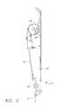
- FIG. 1is a front view of the lumbar support with integrated actuator housing of the present invention.
- FIG. 2is a side view of the lumbar support with integrated actuator housing of the present invention in a flat position.
- FIG. 3is a side view of the lumber support with integrated actuator housing of the present invention in an arched, lumbar supporting position.
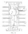
- FIG. 4is a back view of the lumbar support with integrated actuator housing of the present invention.
- FIG. 5is an oblique view of the front of the lumbar support with integrated actuator housing of the present invention.
- FIG. 6is an oblique view of the rear of the lumbar support with integrated actuator housing of the present invention.
- FIG. 7is an exploded view of the lumbar support with integrated actuator housing.
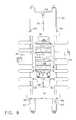
- FIG. 8is a front view of a four-way lumbar support with integrated actuator housing of the present invention.
- FIG. 9is a side view of a four-way version of the lumbar support with integrated actuator housing of the present invention.
- FIG. 10is a back view of the four-way version of the lumbar support with integrated actuator housing of the present invention.
- FIG. 11is an oblique view of the front of the four-way version of the lumbar support with integrated actuator housing of the present invention.
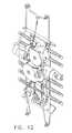
- FIG. 12is an oblique view of the rear of the four-way version of the lumbar support with integrated actuator housing of the present invention.
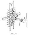
- FIG. 13is an exploded view of the four-way version of the lumbar support.
- FIG. 14is a front view of the four-way version of the integrated actuator housing and pressure surface of the present invention, without any other components assembled.
- FIG. 15is a rear view of the four-way version of the integrated actuator housing and pressure surface of the present invention, without any other components assembled.
- FIG. 16is an oblique view of the four-way version of the integrated actuator housing and pressure surface of the present invention, without any other components assembled.
- FIG. 17is a side view of the four-way version of the integrated actuator housing and pressure surface of the present invention, without any other components assembled.
- FIG. 1is a front view of the lumbar support with integrated actuator housing of the present invention.
- Lumbar support devicesare manufactured in a variety of configurations.
- One type of lumbar support mechanismis characterized by an arching pressure surface which is with an upper region and a lower region. The upper region and lower region are brought closer together by any of a variety of mechanical means, and this closing movement of the ends of the pressure surface bows the pressure surface outwards in an arch that is convex towards the seat occupant.
- the mechanism for arching the pressure surfacecan compress the encapsulated ends, or draw them together by traction.
- the depicted embodimentis a development of the traction family of arching lumbar supports, although a compression embodiment is also considered to be within the scope of the present invention.
- Tractionis typically achieved by means of a cable attached to one end of the arching pressure surface.
- a bracket or other fixation device at the other end of the arching pressure surfacemay anchor the other end in a stationary position.
- the other end of the pressure surfacemay also move, requiring some form of mechanical cooperation with the traction cable. This is often by a bowden cable, whose sleeve is anchored to the other end of the pressure surface.
- the tractive forceis generally actuated either by mechanical means, as by a handwheel or lever, or by an electric motor.
- the present inventionis a development of electric motor traction means.
- FIG. 1is a front view of the lumbar support with integrated actuator housing of the present invention.
- the arching pressure surfaceis indicated generally at 10 .
- the pressure surfaceis commonly made of a single piece of metal or plastic (although, equivalently, it may be assembled from components).
- a typical configurationis to have two vertical bars, 12 , intersecting horizontal transverse ribs, 14 . Together this lattice of vertical and horizontal members projects the seat cushion towards the occupant's lumbar spine to provide lumbar support.
- the general arching pressure surface, 10also incorporates upper and lower regions, 16 and 18 . It is by drawing these two regions together that a supporting convex arch is created in the pressure surface, 10 .
- a traction cable, 20is affixed to the bottom region, 18 , of generalized pressure surface, 10 .
- the traction cable, 20communicates with bottom region, 18 , via spring, 22 .
- the springgraduates the forces between the cable, 20 , and the bottom region, 18 , of the generalized pressure surface, 10 , and also serves to absorb abusive loads put on the device.
- traction cable, 20is attached to the other of the generalized pressure surface terminal regions, in this case upper region 16 .
- this attachmentwould be had by a bracket and the traction cable would continue to a removed position where a mechanical or electrical motor actuator would require a housing or other anchoring to secure it to a seat frame or additional components of the lumbar support.
- traction cable, 20is affixed to upper region, 16 , via the integrated housing, 24 , which is molded into the plastic generalized pressure surface, 10 , at or near the upper region, 16 , as an integral part of it.
- the housing and pressure surfacemay be assembled metal pieces.
- Housing, 24contains the mechanical apparatus to put tractive force on traction cable, 20 , in this case a geared spindle, 26 .
- Geared spindle, 26is powered by electric motor, 28 , which is secured in place at a boss bolted or molded into the integrated pressure surface/housing of the present invention at 30 .
- Engagement of motor, 28rotates spindle, 26 , puts tractive force on cable, 20 , and draws lower region, 18 , towards upper region, 16 , thereby creating an arch in the generalized pressure surface, 10 . In the front view depicted in FIG. 1 the arch would be out of the plane of the page and towards the viewer.
- the upper region, 16 , and housing, 24are fabricated as a solid unit without intervening gaps between the transverse ribs, 14 , or the vertical members, 12 .
- Apex rib, 32 , and bottom rib, 34are different from ribs 14 in their relationship to vertical members, 12 , in that there are intervening holes between the vertical members and apex rib, 32 , and bottom rib, 34 , indicated at 36 . Holes, 36 , create a structure which is weaker between the bottom of the series of ribs, 14 , and bottom rib, 34 .
- top region, 16The absence of holes in top region, 16 , and between ribs 14 creates a part of the general pressure surface, 10 , which is stronger and more resistant to flexion upon the application of tractive force. This creates maximum flexion at the desired location apex rib, 32 . This also creates asymmetrical convexity, which is desirable since it more closely parallels the curvature of the average human spine. Apex rib 32 is located more near the pelvis of the average passenger, while less bowed ribs, 14 would correspond to the upper lumbar vertebrae and lower thoracic area of the average passenger.
- molding housing, 24into upper region, 16 , creates the desired asymmetry in the convexity of the general pressure surface, 10 .
- the integration of housing, 24 , with upper region, 16also adds strength.
- FIGS. 2 and 3side views which demonstrate the functionality of the lumbar support.
- FIG. 2is the lumbar support with traction cable, 20 , relaxed and the generalized pressure surface, 10 , in a substantially flat position.
- FIG. 3shows the general pressure surface in an arched, lumbar supporting position, achieved by applying and holding tractive force to cable, 20 . It can be seen that the apex of the arch occurs substantially at apex rib 32 .
- Dashed line 8indicates the location of a guide wire or rail on which the arching pressure surface slides.
- FIG. 4The back view depicted in FIG. 4 more clearly shows the assembled housing, 24 , enclosing the geared spindle (obscured) and molded boss, 30 , holding motor, 28 .
- Exploded view 7more clearly illustrates the assembly of motor, 28 , inserted into boss, 30 , and housing 24 configured to receive geared spindle, 26 , with traction cable, 20 , partially wound about it and anchored to it.
- Housing cover, 36covers and secures the entire assembly.
- Geared spindle, 26is driven by geared axle, 38 , which is in geared communication with the axle of motor 28 .
- FIGS. 8 through 17Another alternative embodiment of an actuator housing integrated with a general pressure surface is depicted in FIGS. 8 through 17.
- the previous embodiment depicted in FIGS. 1 through 7was capable of moving the lumbar support in two directions: in and out.
- the second embodiment depicted in FIGS. 8 through 17is capable of moving the lumbar support in four directions.
- this embodimentcan raise and lower the whole assembly in order that a seat occupant may move the apex of the lumbar support vertically to the most comfortable position for the occupant's spine.
- Firstis guide wire 50 .
- Guide wire 50serves a dual purpose. First, it is a framework to hold the entire lumbar support unit which may be attached to a seat frame, seat suspension lattice, or back plate according to known technologies.
- the generalized pressure surface 10is slidingly engaged with the long dimension of guide wire 50 by means of slots, holes or clamps disposed at upper region 16 at 54 and lower region 18 at 56 .
- the generalized pressure surface 10moves up and down guide rails 50 as the clamps or slots 54 and 56 slide along the guide rails 50 .
- the “four way” lumbar support unitis depicted in its lowermost position. It can be seen that the downward travel of the generalized pressure surface 10 is arrested at a pre-defined bottom terminus by arresting bends in the guide wires at 60 and 62 . Upwards travel of the generalized pressure surface 10 is arrested by guide wire ends 64 and vertical traction cable anchor 66 .
- Upwards travel of the generalized pressure surface 10 along guide rails 50is actuated by motor 68 driving geared spindle 70 in order to apply a tractive force to vertical travel on traction cable 72 .
- traction cableBesides a traction cable, other force transmission components may be used, such as a rack and pinion or a cable enaaaed with a pulley.
- the geared spindle 70By rotating the geared spindle 70 in a direction to take in vertical travel traction cable 72 (clockwise in front view FIG. 8) the generalized pressure surface 10 is pulled in an upwards direction along guide rails 50 . Opposing this force are downward traction springs 74 .
- the tension on these springs, gearing of geared spindle 70 and torque of electric motor 68are pre-configured so that actuation of motor 68 is capable of overcoming the tractive tension of springs 74 so that the lumbar support may be moved upwards.
- the tractive force of springs 74are also pre-configured to be able to draw the generalized pressure surface 10 back down when the tractive force on vertical travel traction cable 72 is released.
- FIGS. 14 through 17depict the single part, the integrated pressure surface and actuator housing, without the other assembly components.
- the advantageous compact nature of the present inventionallows sufficient space on the back of the generalized pressure surface for molding in two actuator housings and two motor support bosses to facilitate four way control of the lumbar support as well as two way control.
- the compact designallows extra room in the seat for installation of other components.
- the integrated lumbar support and actuator housing of the present inventionalso facilitates ease of assembly and reduces component costs by eliminating the need for separate fixation and additional components for that fixation otherwise necessary for anchoring actuators and actuator motors external to the lumbar support.
Landscapes
- Engineering & Computer Science (AREA)
- Aviation & Aerospace Engineering (AREA)
- Transportation (AREA)
- Mechanical Engineering (AREA)
- Seats For Vehicles (AREA)
- Chair Legs, Seat Parts, And Backrests (AREA)
Abstract
Description
None
Not Applicable
1. Field of the Invention
This invention relates generally to ergonomic weight support devices, especially arching lumbar supports for seats.
2. Related Art
Lumbar supports for seats, particularly automobile seats, are known. See U.S. Pat. Nos. 5,050,930; 5,397,164; 5,498,063; 5,626,390; 5,775,773; 6,003,941; 4,354,709; 4,452,485; 4,632,454; 4,880,271; GB 2 013 487A and D 169 293 B1. These devises all have in common one or more flexible members that may be flexed in order to create a convex surface with its apex towards the lumbar spine of a human being sitting in the seat into which the device is incorporated. This convex flexion is induced by any of a great variety of means for compression, See, e.g., U.S. Pat. No. 4,354,709 or tension, See, e.g., U.S. Pat. No. 5,498,063. It is common among these prior art lumbar supports that both an upper extremity of the convex pressure element and the lower extremity of it are anchored to a framework within the seat. These upper and lower elements may be fixedly anchored or movably anchored, or a combination of the two, so long as they may be pulled or pushed closer together to project an apex of the convexity farther out from the plane of the seat for greater lumbar support. Conversely, tension may be released in order to move the apex of the convexity closer to the plane of the seat for less lumbar support.
Whether the pressure producing a greater or lesser convexity is produced by compression or tension, all prior art lumbar support devices have used multiple moving parts, many of which are under dynamic tension for actuation of the convexity, and again under dynamic tension for supporting the weight of the seat passenger. The multiplicity of moving parts in prior art lumbar supports complicates manufacture, increases expense of materials necessary, increases the likelihood of component failure and shortens the life span of the devices.
Moreover, prior art lumbar supports require a relatively large amount of space to accommodate the relatively cumbersome tensioning or compression apparatuses, together with the frameworks necessary for their support.
As seat designs are modified to incorporate more comfort devices, such as duct work for heating and cooling, the amount of space available inside seats for lumbar support devices shrinks. There is need for smaller lumbar supports.
There is a need in the art for a universal ergonomic support which occupies less space, costs less to manufacture and install, simplifies manufacture, decreases needed components, uses a more robust mechanism for supporting the weight of a human passenger and/or may be more universally used for lumbar, head and neck and thigh support as well as only lumbar support.
This invention is an integrated lumbar support pressure plate and actuator motor housing. Conventional lumbar supports typically flex a pressure surface into an arch by means of traction drawing together the ends of the pressure plate. This tension is frequently actuated by means of a traction cable powered by an electric motor.
Prior configurations of lumbar supports generally located the actuator motor outside the profile of the pressure surface. The present invention locates the actuator motor within the profile of the pressure surface, saving space. Moreover, the present invention actually incorporates the housing for the electric motor on the back of the pressure surface itself, reducing the need for additional components and assembly time to attach the motor to a seat-frame.
The pressure surface/motor housing is a single molded plastic unit. The actuator motor is anchored in its housing on the back of the pressure surface. Upon engagement of the motor it draws a traction cable that is directed to engage both ends of the pressure surface in order to draw them together. The longer the motor is engaged, the closer together the cable draws the ends of the pressure surface, and thereby the greater the degree of convexity of the pressure surface. Releasing the tension lengthens the traction cable and flattens the pressure surface. In this manner a seat occupant can control the degree of lumbar support.
The present invention reduces the number of components necessary to assemble a lumbar support unit. It is compact in size for ease of packaging, and ease of incorporation into a variety of different seats. The present invention reduces costs required to manufacture, sell, assemble, maintain and operate the lumbar support. The present invention eases and streamlines the manufacture of the lumbar supports and of seats incorporating it, to lower production cost and increase durability and useful life.
The present invention may be incorporated easily with existing components, for example, seat frames, and with future seats that may have less space available within them. It does not require guide wires, outside actuators, attachment brackets or long cables.
Further features and advantages of the present invention, as well as the structure and operations and various embodiments of the present invention, are described in detail below with reference to the accompanying drawing.
FIG. 1 is a front view of the lumbar support with integrated actuator housing of the present invention.
FIG. 2 is a side view of the lumbar support with integrated actuator housing of the present invention in a flat position.
FIG. 3 is a side view of the lumber support with integrated actuator housing of the present invention in an arched, lumbar supporting position.
FIG. 4 is a back view of the lumbar support with integrated actuator housing of the present invention.
FIG. 5 is an oblique view of the front of the lumbar support with integrated actuator housing of the present invention.
FIG. 6 is an oblique view of the rear of the lumbar support with integrated actuator housing of the present invention.
FIG. 7 is an exploded view of the lumbar support with integrated actuator housing.
FIG. 8 is a front view of a four-way lumbar support with integrated actuator housing of the present invention.
FIG. 9 is a side view of a four-way version of the lumbar support with integrated actuator housing of the present invention.
FIG. 10 is a back view of the four-way version of the lumbar support with integrated actuator housing of the present invention.
FIG. 11 is an oblique view of the front of the four-way version of the lumbar support with integrated actuator housing of the present invention.
FIG. 12 is an oblique view of the rear of the four-way version of the lumbar support with integrated actuator housing of the present invention.
FIG. 13 is an exploded view of the four-way version of the lumbar support.
FIG. 14 is a front view of the four-way version of the integrated actuator housing and pressure surface of the present invention, without any other components assembled.
FIG. 15 is a rear view of the four-way version of the integrated actuator housing and pressure surface of the present invention, without any other components assembled.
FIG. 16 is an oblique view of the four-way version of the integrated actuator housing and pressure surface of the present invention, without any other components assembled.
FIG. 17 is a side view of the four-way version of the integrated actuator housing and pressure surface of the present invention, without any other components assembled.
Referring to the accompanying drawings in which like reference numbers indicate like elements, FIG. 1 is a front view of the lumbar support with integrated actuator housing of the present invention.
Lumbar support devices are manufactured in a variety of configurations. One type of lumbar support mechanism is characterized by an arching pressure surface which is with an upper region and a lower region. The upper region and lower region are brought closer together by any of a variety of mechanical means, and this closing movement of the ends of the pressure surface bows the pressure surface outwards in an arch that is convex towards the seat occupant. The mechanism for arching the pressure surface can compress the encapsulated ends, or draw them together by traction. The depicted embodiment is a development of the traction family of arching lumbar supports, although a compression embodiment is also considered to be within the scope of the present invention.
Traction is typically achieved by means of a cable attached to one end of the arching pressure surface. A bracket or other fixation device at the other end of the arching pressure surface may anchor the other end in a stationary position. Alternatively, the other end of the pressure surface may also move, requiring some form of mechanical cooperation with the traction cable. This is often by a bowden cable, whose sleeve is anchored to the other end of the pressure surface. The tractive force is generally actuated either by mechanical means, as by a handwheel or lever, or by an electric motor. The present invention is a development of electric motor traction means.
FIG. 1 is a front view of the lumbar support with integrated actuator housing of the present invention. The arching pressure surface is indicated generally at10. The pressure surface is commonly made of a single piece of metal or plastic (although, equivalently, it may be assembled from components). A typical configuration is to have two vertical bars,12, intersecting horizontal transverse ribs,14. Together this lattice of vertical and horizontal members projects the seat cushion towards the occupant's lumbar spine to provide lumbar support.
The general arching pressure surface,10, also incorporates upper and lower regions,16 and18. It is by drawing these two regions together that a supporting convex arch is created in the pressure surface,10. In the depicted embodiment, a traction cable,20, is affixed to the bottom region,18, of generalized pressure surface,10. In this alternative embodiment the traction cable,20, communicates with bottom region,18, via spring,22. The spring graduates the forces between the cable,20, and the bottom region,18, of the generalized pressure surface,10, and also serves to absorb abusive loads put on the device.
The other end of traction cable,20, is attached to the other of the generalized pressure surface terminal regions, in this caseupper region 16. In the prior art this attachment would be had by a bracket and the traction cable would continue to a removed position where a mechanical or electrical motor actuator would require a housing or other anchoring to secure it to a seat frame or additional components of the lumbar support. In the present invention traction cable,20, is affixed to upper region,16, via the integrated housing,24, which is molded into the plastic generalized pressure surface,10, at or near the upper region,16, as an integral part of it. Alternatively, the housing and pressure surface may be assembled metal pieces.
Housing,24, contains the mechanical apparatus to put tractive force on traction cable,20, in this case a geared spindle,26. Geared spindle,26, is powered by electric motor,28, which is secured in place at a boss bolted or molded into the integrated pressure surface/housing of the present invention at30. Engagement of motor,28, rotates spindle,26, puts tractive force on cable,20, and draws lower region,18, towards upper region,16, thereby creating an arch in the generalized pressure surface,10. In the front view depicted in FIG. 1 the arch would be out of the plane of the page and towards the viewer.
The upper region,16, and housing,24, are fabricated as a solid unit without intervening gaps between the transverse ribs,14, or the vertical members,12. Apex rib,32, and bottom rib,34, are different fromribs 14 in their relationship to vertical members,12, in that there are intervening holes between the vertical members and apex rib,32, and bottom rib,34, indicated at36. Holes,36, create a structure which is weaker between the bottom of the series of ribs,14, and bottom rib,34. The absence of holes in top region,16, and betweenribs 14 creates a part of the general pressure surface,10, which is stronger and more resistant to flexion upon the application of tractive force. This creates maximum flexion at the desired location apex rib,32. This also creates asymmetrical convexity, which is desirable since it more closely parallels the curvature of the average human spine.Apex rib 32 is located more near the pelvis of the average passenger, while less bowed ribs,14 would correspond to the upper lumbar vertebrae and lower thoracic area of the average passenger. Hence molding housing,24, into upper region,16, creates the desired asymmetry in the convexity of the general pressure surface,10. The integration of housing,24, with upper region,16, also adds strength.
The advantage of this configuration is more apparent in FIGS. 2 and 3, side views which demonstrate the functionality of the lumbar support. FIG. 2 is the lumbar support with traction cable,20, relaxed and the generalized pressure surface,10, in a substantially flat position. FIG. 3 shows the general pressure surface in an arched, lumbar supporting position, achieved by applying and holding tractive force to cable,20. It can be seen that the apex of the arch occurs substantially atapex rib 32. Dashedline 8 indicates the location of a guide wire or rail on which the arching pressure surface slides.
The back view depicted in FIG. 4 more clearly shows the assembled housing,24, enclosing the geared spindle (obscured) and molded boss,30, holding motor,28.
Exploded view7 more clearly illustrates the assembly of motor,28, inserted into boss,30, andhousing 24 configured to receive geared spindle,26, with traction cable,20, partially wound about it and anchored to it. Housing cover,36, covers and secures the entire assembly. Geared spindle,26, is driven by geared axle,38, which is in geared communication with the axle ofmotor 28.
A variety of embodiments are considered to be within the scope of the present invention. Another alternative embodiment of an actuator housing integrated with a general pressure surface is depicted in FIGS. 8 through 17. The previous embodiment depicted in FIGS. 1 through 7 was capable of moving the lumbar support in two directions: in and out. The second embodiment depicted in FIGS. 8 through 17 is capable of moving the lumbar support in four directions. In addition to bowing the arching pressure surface in and out, this embodiment can raise and lower the whole assembly in order that a seat occupant may move the apex of the lumbar support vertically to the most comfortable position for the occupant's spine.
FIGS. 8, a front view,9, a side view,10, a back view,11, an oblique back view,12, an oblique front view, and13, an exploded view depict the additional components for adding the raising and lowering capability to this embodiment. First isguide wire 50.Guide wire 50 serves a dual purpose. First, it is a framework to hold the entire lumbar support unit which may be attached to a seat frame, seat suspension lattice, or back plate according to known technologies. Secondly, thegeneralized pressure surface 10 is slidingly engaged with the long dimension ofguide wire 50 by means of slots, holes or clamps disposed atupper region 16 at54 andlower region 18 at56. Thegeneralized pressure surface 10 moves up and downguide rails 50 as the clamps orslots generalized pressure surface 10 is arrested at a pre-defined bottom terminus by arresting bends in the guide wires at60 and62. Upwards travel of thegeneralized pressure surface 10 is arrested by guide wire ends64 and verticaltraction cable anchor 66.
Upwards travel of thegeneralized pressure surface 10 alongguide rails 50 is actuated bymotor 68 driving gearedspindle 70 in order to apply a tractive force to vertical travel ontraction cable 72. Besides a traction cable, other force transmission components may be used, such as a rack and pinion or a cable enaaaed with a pulley. By rotating the gearedspindle 70 in a direction to take in vertical travel traction cable72 (clockwise in front view FIG. 8) thegeneralized pressure surface 10 is pulled in an upwards direction along guide rails50. Opposing this force are downward traction springs74. The tension on these springs, gearing of gearedspindle 70 and torque ofelectric motor 68 are pre-configured so that actuation ofmotor 68 is capable of overcoming the tractive tension ofsprings 74 so that the lumbar support may be moved upwards. The tractive force ofsprings 74 are also pre-configured to be able to draw thegeneralized pressure surface 10 back down when the tractive force on verticaltravel traction cable 72 is released.
The in and out bowing of the generalized pressure surface convex arch is controlled by the cooperative operation ofmotor 76, gearedspindle 78 andtraction cable 80 in the same manner as described above in the “two way” lumbar support.
FIGS. 14 through 17 depict the single part, the integrated pressure surface and actuator housing, without the other assembly components.
It can be readily appreciated that the advantageous compact nature of the present invention allows sufficient space on the back of the generalized pressure surface for molding in two actuator housings and two motor support bosses to facilitate four way control of the lumbar support as well as two way control. The compact design allows extra room in the seat for installation of other components.
Those of skill in the art will recognize that the integrated lumbar support and actuator housing of the present invention also facilitates ease of assembly and reduces component costs by eliminating the need for separate fixation and additional components for that fixation otherwise necessary for anchoring actuators and actuator motors external to the lumbar support.
In view of the foregoing, it will be seen that the several advantages of the invention are achieved and attained.
The embodiments were chosen and described in order to best explain the principles of the invention and its practical application to thereby enable others skilled in the art to best utilize the invention in various embodiments and with various modifications as are suited to the particular use contemplated.
As various modifications could be made in the constructions and methods herein described and illustrated without departing from the scope of the invention, it is intended that all matter contained in the foregoing description or shown in the accompanying drawings shall be interpreted as illustrative rather than limiting. Thus, the breadth and scope of the present invention should not be limited by any of the above described exemplary embodiments, but should be defined only in accordance with the following claims appended hereto and their equivalents.
Claims (20)
1. A lumbar support with an integrated actuator housing and pressure surface comprising:
an arching pressure surface having an upper region and a lower region;
an actuator housing fixed to one of said upper region or said lower region of said arching pressure surface, said actuator housing and said arching pressure surface being integrally fabricated from a single piece of material;
motorized actuator disposed within said actuator housing; and
a traction element having a first portion and a second portion, said first portion being in communication with one of said upper region or said lower region of said arching pressure surface, said second portion being in communication with the other of said upper region or said lower region of said arching pressure surface such that tension on said traction element exerted though said actuator housing draws said upper region and said lower region of said arching pressure surface toward one another to form an arch.
2. The lumbar support ofclaim 1 wherein said traction element is a cable.
3. The lumbar support ofclaim 1 wherein said archable pressure surface further comprises ribs.
4. The lumbar support ofclaim 1 wherein said second portion of said traction element is in communication with the other of said upper or said lower region of said arching pressure surface via a spring.
5. The lumbar support ofclaim 1 , further comprising at least one pulley disposed between said traction element and said pressure surface.
6. The lumbar supportclaim 1 wherein said actuator is an electric motor.
7. The lumbar support ofclaim 1 wherein said pressure surface and said housing are molded from a single piece of plastic.
8. The lumbar support ofclaim 1 wherein said pressure surface and said housing are stamped from a single piece of metal.
9. The lumbar support ofclaim 1 wherein said arching pressure surface slides on guide rails.
10. A lumbar support for a seat with an integrated actuator housing comprising:
a pressure surface having an upper region and a lower region;
an actuator housing attached to said upper region, said actuator housing and said arching pressure surface being integrally fabricated from a single piece of material;
motorized actuator held by said actuator housing, said actuator comprising;
a geared spindle, and
an electric motor in geared, driving communication with said spindle;
a traction cable having a first portion and a second portion, said first portion being in communication with said spindle and said second portion being in communication with said lower region of said pressure surface;
whereby actuation of said electric motor rotates said geared spindle, rotation of said spindle puts tension on said cable, and said cable draws said upper region of said pressure surface toward said lower region of said pressure surface to create an arch in said pressure surface.
11. A method of fabricating a lumbar support for a seat comprising:
integrally fabricating from a single piece of material an actuator housing and an archable pressure surface, said actuator housing being on either of an upper region or a lower region of said archable pressure surface;
housing an actuator in said actuator housing; and
linking a first portion of a traction element to said traction actuator and a second portion of said traction element to the other of said upper region or said lower region of said pressure surface.
12. The method ofclaim 11 wherein said attaching is by stamping said archable pressure surface and said actuator housing together from metal.
13. The method ofclaim 11 wherein said attaching is by molding said pressure surface and said housing from a single piece of plastic.
14. The method ofclaim 11 wherein said actuator is an electric motor in driving, geared communication with a geared spindle.
15. The method ofclaim 11 wherein said traction element is a cable.
16. The method ofclaim 11 wherein said linking of said traction element to said pressure surface is via a spring.
17. A pressure surface for a lumbar support comprising:
an archable pressure surface having an upper region and a lower region;
an actuator housing attached to one of said upper region or said lower region of
said archable pressure surface, said actuator housing and said arching pressure surface being integrally fabricated from a single piece of material;
motorized actuator, disposed in said actuator housing; and
a force transmission element linked to said actuator, said force transmission element also being linked to the other of said upper region or said lower region on said archable pressure surface.
18. The pressure surface ofclaim 17 wherein said pressure surface and said actuator housing are molded from a single piece of plastic.
19. The pressure surface of vlsim17 wherein said archable pressure surface and said actuator housing are stamped metal.
20. A lumbar support with an integrated actuator housing and pressure surface comprising:
an arching pressure surface having an upper region and a lower region;
actuator housing fixed to one of said upper region or said lower region of said arching pressure surface, such that an actuator mounted in said actuator housing is within a perimeter of said arching pressure surface said actuator housing and said arching pressure surface being integrally fabricated from a single piece of material;
a motorized actuator disposed within said actuator housing; and
a traction element having a first portion and a second portion, said first portion being in communication with one of said upper region or said lower region of said arching pressure surface, said second portion being in communication with the other of said upper region or said lower region of said arching pressure surface such that tension on said traction element exerted though said actuator housing draws said upper region and said lower region of said arching pressure surface toward one another to form an arch.
Priority Applications (4)
| Application Number | Priority Date | Filing Date | Title |
|---|---|---|---|
| US09/993,579US6676214B2 (en) | 2001-11-16 | 2001-11-16 | Method and apparatus for lumbar support with integrated actuator housing |
| PCT/US2002/036457WO2003043849A1 (en) | 2001-11-16 | 2002-11-13 | Method and apparatus for lumbar support with integrated actuator housing |
| AU2002343694AAU2002343694A1 (en) | 2001-11-16 | 2002-11-13 | Method and apparatus for lumbar support with integrated actuator housing |
| US10/704,246US6893089B2 (en) | 2001-11-16 | 2003-11-07 | Method and apparatus for lumbar support with integrated actuator housing |
Applications Claiming Priority (1)
| Application Number | Priority Date | Filing Date | Title |
|---|---|---|---|
| US09/993,579US6676214B2 (en) | 2001-11-16 | 2001-11-16 | Method and apparatus for lumbar support with integrated actuator housing |
Related Child Applications (1)
| Application Number | Title | Priority Date | Filing Date |
|---|---|---|---|
| US10/704,246ContinuationUS6893089B2 (en) | 2001-11-16 | 2003-11-07 | Method and apparatus for lumbar support with integrated actuator housing |
Publications (2)
| Publication Number | Publication Date |
|---|---|
| US20030094841A1 US20030094841A1 (en) | 2003-05-22 |
| US6676214B2true US6676214B2 (en) | 2004-01-13 |
Family
ID=25539716
Family Applications (2)
| Application Number | Title | Priority Date | Filing Date |
|---|---|---|---|
| US09/993,579Expired - LifetimeUS6676214B2 (en) | 2001-11-16 | 2001-11-16 | Method and apparatus for lumbar support with integrated actuator housing |
| US10/704,246Expired - Fee RelatedUS6893089B2 (en) | 2001-11-16 | 2003-11-07 | Method and apparatus for lumbar support with integrated actuator housing |
Family Applications After (1)
| Application Number | Title | Priority Date | Filing Date |
|---|---|---|---|
| US10/704,246Expired - Fee RelatedUS6893089B2 (en) | 2001-11-16 | 2003-11-07 | Method and apparatus for lumbar support with integrated actuator housing |
Country Status (3)
| Country | Link |
|---|---|
| US (2) | US6676214B2 (en) |
| AU (1) | AU2002343694A1 (en) |
| WO (1) | WO2003043849A1 (en) |
Cited By (40)
| Publication number | Priority date | Publication date | Assignee | Title |
|---|---|---|---|---|
| US20030136443A1 (en)* | 2002-01-16 | 2003-07-24 | Wain Robert Edwin | Component position indicating apparatus |
| US20030171197A1 (en)* | 2002-03-06 | 2003-09-11 | Fitnesslab, Llc. | Variable radius flexibility apparatus |
| US20040113472A1 (en)* | 2001-11-16 | 2004-06-17 | L & P Property Management Company | Method and apparatus for lumbar support with integrated actuator housing |
| US20050023873A1 (en)* | 2001-07-11 | 2005-02-03 | Massara Andrew J. | Integrated adjustable lumbar support and trim attachment system |
| US20050223590A1 (en)* | 2004-04-12 | 2005-10-13 | Erickson Robert W | Restraining device for reducing warp in lumber during drying |
| US6955399B2 (en)* | 2002-01-26 | 2005-10-18 | Cheong Myung Hong | Lumbar support for car seat |
| US7000986B2 (en)* | 2001-09-28 | 2006-02-21 | Ficosa North America | Lumbar support apparatus |
| US20060038433A1 (en)* | 2001-11-05 | 2006-02-23 | Schurka Europa Gmbh | Device for displaying a seat component |
| US20060226683A1 (en)* | 2005-04-08 | 2006-10-12 | Alfmeier Corporation | Adjustable lumbar support with extensive configurability |
| US20070063561A1 (en)* | 2005-08-23 | 2007-03-22 | Schukra Of North America, Ltd. | Comfort belt spring pulley |
| US20070102977A1 (en)* | 2003-09-04 | 2007-05-10 | Markus Fischer | Motor vehicle seat back structure for a motor vehicle seat (as amended) |
| US20070228789A1 (en)* | 2006-03-30 | 2007-10-04 | Schukra Of North America | Combination Lumbar-Bolster System |
| US20070236063A1 (en)* | 2006-04-07 | 2007-10-11 | Schukra Of North America, Ltd. | Overmolded thin-profile lumbar support |
| US7328950B2 (en)* | 2005-05-18 | 2008-02-12 | Schukra Of North America, Ltd. | Dual hinge belt lumbar |
| US20080238123A1 (en)* | 2005-04-08 | 2008-10-02 | Alfmeier Prazision Ag Baugrupper Und Systemlosungen | Vehicle Seat with Lordosis Support |
| US20090096263A1 (en)* | 2005-01-12 | 2009-04-16 | L&P Swiss Holding Company | Lumbar Support Assembly and Corresponding Seat Structure |
| US20090134679A1 (en)* | 2007-11-28 | 2009-05-28 | Ford Global Technologies, Llc | Combined manual recline and manual lumbar adjustment mechanism |
| US7614696B2 (en) | 2006-12-11 | 2009-11-10 | Schukra Of North America | Lumbar system for climate seating |
| US7690726B2 (en) | 2005-01-12 | 2010-04-06 | L&P Swiss Holding Company | Coupling unit and adjusting mechanism using the coupling unit |
| US20110062757A1 (en)* | 2009-09-14 | 2011-03-17 | Renato Colja | Pelvic and lumbar support |
| US20110115268A1 (en)* | 2009-11-16 | 2011-05-19 | Gunter Maierhofer | Adjusting device for a lumbar support and method of adjusting a lumbar support |
| US20110127817A1 (en)* | 2009-11-30 | 2011-06-02 | Hyundai Motor Company | Lumbar supporting device for vehicle |
| US7997650B2 (en) | 2008-02-22 | 2011-08-16 | Schukra Of North America | Constant pressure retreating lumbar system |
| DE102010010604B3 (en)* | 2010-03-08 | 2012-01-12 | Isringhausen Gmbh & Co. Kg | Frame-shaped carrier structure for vehicle seat, has two side parts and pad carrier, which is connected with side parts |
| US20130334853A1 (en)* | 2011-03-28 | 2013-12-19 | L&P Swiss Holding Ag | Actuator arrangement for a seat and adjusting method |
| US8684460B2 (en) | 2011-06-15 | 2014-04-01 | Brose Fahrzeugteile Gmbh & Co. Kg, Coburg | Backrest structure for a seat with lumbar support and curving element comprising a pre-tensioning connecting element |
| DE102012111888A1 (en)* | 2012-12-06 | 2014-06-12 | Recaro Aircraft Seating Gmbh & Co. Kg | Seat component of vehicle seat e.g. aircraft seat has transmission unit that translates force component in direction of bearing surface corresponding to movement of seat unit towards motion resistant direction |
| US8991923B2 (en) | 2009-11-16 | 2015-03-31 | Schukra Geraetebau Gmbh | Adjusting device for a lumbar support and method of adjusting a lumbar support |
| US9193280B2 (en) | 2012-09-13 | 2015-11-24 | Leggett & Platt Canada Co. | Lumbar support system |
| US9193287B2 (en) | 2012-09-13 | 2015-11-24 | Leggett & Platt Canada Co. | Lumbar support system |
| US9199565B2 (en) | 2012-09-13 | 2015-12-01 | Leggett & Platt Canada Co. | Lumbar support system |
| US20160355115A1 (en)* | 2015-06-02 | 2016-12-08 | Hyundai Motor Company | Lumbar support assembly |
| US9744891B2 (en)* | 2015-04-03 | 2017-08-29 | Dae Chang Seat Co., Ltd. | Lumbar support assembly |
| US20190315255A1 (en)* | 2018-04-12 | 2019-10-17 | Ts Tech Co., Ltd. | Conveyance seat |
| US10632882B2 (en) | 2012-09-13 | 2020-04-28 | Leggett & Platt Canada Co. | Lumbar support system |
| US10857919B2 (en)* | 2019-01-28 | 2020-12-08 | Brose Fahrzeugteile Gmbh & Co. Kommanditgesellschaft, Coburg | Lumbar mat for a backrest structure |
| US10952535B2 (en) | 2018-11-05 | 2021-03-23 | La-Z-Boy Incorporated | Furniture member having lumbar adjustment mechanism |
| US11324324B2 (en) | 2018-11-05 | 2022-05-10 | La-Z-Boy Incorporated | Furniture member having lumbar adjustment mechanism |
| US11472322B1 (en)* | 2021-06-08 | 2022-10-18 | Brose Fahrzeugteile SE & Co. Kommanditgesellschaft, Coburg | Lumbar adjustment assembly |
| US11672348B2 (en) | 2018-11-05 | 2023-06-13 | La-Z-Boy Incorporated | Furniture member having lumbar adjustment mechanism |
Families Citing this family (13)
| Publication number | Priority date | Publication date | Assignee | Title |
|---|---|---|---|---|
| US7458637B2 (en)* | 2004-06-10 | 2008-12-02 | Steelcase Inc. | Back construction with flexible lumbar |
| US7237841B2 (en)* | 2004-06-10 | 2007-07-03 | Steelcase Development Corporation | Back construction with flexible lumbar |
| JP2006026315A (en)* | 2004-07-21 | 2006-02-02 | Johnson Controls Technol Co | Lumbar support for automobile |
| DE602007001694D1 (en)* | 2007-09-21 | 2009-09-03 | Ciar Spa | lumbar support |
| US20090287120A1 (en) | 2007-12-18 | 2009-11-19 | Searete Llc, A Limited Liability Corporation Of The State Of Delaware | Circulatory monitoring systems and methods |
| US9717896B2 (en) | 2007-12-18 | 2017-08-01 | Gearbox, Llc | Treatment indications informed by a priori implant information |
| US8636670B2 (en) | 2008-05-13 | 2014-01-28 | The Invention Science Fund I, Llc | Circulatory monitoring systems and methods |
| KR101046606B1 (en)* | 2009-02-20 | 2011-07-06 | 주식회사다스 | Lumber support of seat |
| KR101507706B1 (en) | 2009-07-15 | 2015-04-07 | 존슨 컨트롤스 게엠베하 | Drive device for a bowden cable |
| KR101199906B1 (en)* | 2010-06-24 | 2012-11-09 | (주)디에스시 | Lumber support assembly |
| JP5962490B2 (en)* | 2012-12-19 | 2016-08-03 | トヨタ紡織株式会社 | Vehicle seat |
| EP2910415B1 (en)* | 2014-02-25 | 2018-11-07 | Schukra Gerätebau GmbH | Actuator assembly and method for seat adjustment |
| JP6766695B2 (en)* | 2017-03-03 | 2020-10-14 | トヨタ紡織株式会社 | Vehicle seat |
Citations (114)
| Publication number | Priority date | Publication date | Assignee | Title |
|---|---|---|---|---|
| US1182854A (en) | 1915-05-10 | 1916-05-09 | Albert J Coe | Flexible back adjustment for chairs. |
| US2756809A (en) | 1954-06-30 | 1956-07-31 | Endresen Ernst | Back support for chairs, car seats, and the like |
| US2843195A (en) | 1956-01-25 | 1958-07-15 | Alvar E A Barvaeus | Self-adjusting back support |
| US2942651A (en) | 1957-11-12 | 1960-06-28 | Market Forge Company | Auxiliary seat |
| US3378299A (en) | 1966-07-05 | 1968-04-16 | William C. Sandor | Automobile seating construction |
| US3490084A (en) | 1967-01-25 | 1970-01-20 | Wilhelm Schuster | Resilient support |
| US3492768A (en) | 1967-04-11 | 1970-02-03 | Wilhelm Schuster | Resilient support |
| US3724144A (en) | 1969-12-12 | 1973-04-03 | W Schuster | Reinforcing structure for bodies with curved load-supporting surfaces |
| US3762769A (en) | 1970-12-30 | 1973-10-02 | Recaro Ag | Seat especially for motor vehicles |
| GB1423617A (en) | 1972-10-09 | 1976-02-04 | Zuend Co Ag Karl | Back rests for chairs or the like |
| US4014422A (en) | 1974-11-07 | 1977-03-29 | Ryobi, Ltd. | Reel mechanism |
| SU587924A2 (en) | 1976-04-05 | 1978-01-15 | Belyaev Vladimir L | Armchair |
| US4136577A (en) | 1975-11-10 | 1979-01-30 | Ab Volvo Penta | Device for connecting either one of two alternative operating members with an operated member |
| US4153293A (en) | 1977-09-06 | 1979-05-08 | Nepsco, Inc. | Back rest |
| US4156544A (en) | 1978-03-20 | 1979-05-29 | Milsco Manufacturing Company | Vehicle seat having lumbar support adjustment means |
| US4182533A (en) | 1978-12-26 | 1980-01-08 | Uop Inc. | Seat backrest having an adjustable lumbar support |
| US4295681A (en) | 1980-02-19 | 1981-10-20 | Uop Inc. | Seat having lumbar support and vertical height adjustment mechanism therefor |
| US4313637A (en) | 1978-11-18 | 1982-02-02 | Uop Inc. | Seat having a movable lumbar support |
| EP0006840B1 (en) | 1978-06-23 | 1982-02-03 | Wilhelm Ing. Schuster | Flexible elastic support |
| US4316631A (en) | 1979-01-24 | 1982-02-23 | Steyr-Daimler-Puch Aktiengesellschaft | Backrest |
| GB2013487B (en) | 1978-02-03 | 1982-09-15 | Menacher P M R | Back rest with lumbar support |
| US4390210A (en) | 1980-12-15 | 1983-06-28 | Haworth Mfg., Inc. | Blind connecting structure for inner and outer shells of chair back |
| US4425910A (en)* | 1980-12-05 | 1984-01-17 | Hermann Meiller | Seat having an adjustable backrest |
| US4449751A (en) | 1981-05-26 | 1984-05-22 | Lear Siegler, Inc. | Seat backrest having an adjustable lumbar support |
| US4465317A (en) | 1980-01-26 | 1984-08-14 | Johann Schwarz | Mechanism for adjusting a lumbar support of a back of a seat or the like |
| US4494709A (en) | 1982-09-01 | 1985-01-22 | Juichiro Takada | Seat belt retractor with an automatically memorized tensionless position |
| US4541670A (en) | 1983-08-15 | 1985-09-17 | Robin Morgenstern | Lumbosacral backrest with adjustable contour |
| US4555140A (en) | 1984-02-23 | 1985-11-26 | Japan | Vehicle seat |
| US4556251A (en) | 1983-10-18 | 1985-12-03 | Tachikawa Spring Co., Ltd. | Lumbar support device |
| US4561606A (en) | 1982-10-21 | 1985-12-31 | Nippon Soken, Inc. | Seat belt retractor of automobile |
| US4564235A (en) | 1984-11-09 | 1986-01-14 | Tachikawa Spring Co., Ltd. | Lumbar support device |
| US4565406A (en) | 1984-03-29 | 1986-01-21 | Tachikawa Spring Co., Ltd. | Lumbar support device |
| US4576410A (en) | 1982-05-26 | 1986-03-18 | Aisen Seiki Kabushika Kaisha | Lumbar support for a backrest |
| US4601514A (en)* | 1983-07-08 | 1986-07-22 | Messrs. Willibald Grammer | Seat having an adjustable back support arrangement |
| US4602819A (en) | 1982-05-27 | 1986-07-29 | I.T.W. De France | Part adapted to ensure comfort in a vehicle seat, especially an automotive vehicle seat |
| US4627661A (en) | 1983-01-27 | 1986-12-09 | Be - Ge Stolindustri Ab | Chair back with adjustable lumbar support |
| US4632454A (en) | 1983-11-09 | 1986-12-30 | Ab Volvo | Vehicle seat intended, for example, for such automobile vehicles as cars, trains and airplanes |
| US4676550A (en) | 1983-06-14 | 1987-06-30 | Marcel Neve De Mevergnies | Seat for vehicle, particularly motor vehicle |
| US4679848A (en) | 1985-02-11 | 1987-07-14 | Spierings Petrus A M | Back support mechanism and method |
| US4730871A (en) | 1986-08-14 | 1988-03-15 | Nepsco, Inc. | Adjustable back rest |
| DE2947472C2 (en) | 1979-01-24 | 1988-06-30 | Steyr-Daimler-Puch Ag, Wien, At | |
| EP0322535A1 (en) | 1987-12-28 | 1989-07-05 | Wickes Manufacturing Company | Adjustable lumbar support |
| US4880271A (en)* | 1987-12-28 | 1989-11-14 | Wickes Manufacturing Company | Adjustable lumbar support |
| US4909568A (en) | 1987-10-16 | 1990-03-20 | Fiat Auto S.P.A. | Adjustable backrest for the seats of vehicles, particularly cars |
| US4915448A (en) | 1988-07-11 | 1990-04-10 | Morgenstern Robin L | Power actuated lumbosacral backrest |
| US4950032A (en) | 1989-03-31 | 1990-08-21 | Shiroki Corporation | Seat having vertically movable lumber support |
| US4957102A (en) | 1987-09-30 | 1990-09-18 | Ikeda Bussan Co., Ltd. | Lumbar support device |
| FR2596334B1 (en) | 1986-03-25 | 1990-10-05 | Renault | SEAT FOLDER WITH LUMP SUPPORT ADJUSTMENT DEVICE |
| US5005904A (en) | 1988-03-01 | 1991-04-09 | Pirelli Limited | System for inflating support bag in seat |
| US5022709A (en) | 1988-02-12 | 1991-06-11 | Piero Marchino | Springing and wrap-around element for a seat and/or backrest, and seat embodying the same |
| US5050930A (en)* | 1989-08-04 | 1991-09-24 | Wilhelm Schuster | Lordosis-support backrest for a vehicle seat |
| US5076643A (en) | 1990-08-20 | 1991-12-31 | Lear Seating Corporation | Lumbar support |
| US5088790A (en) | 1990-05-21 | 1992-02-18 | Lear Seating Corporation | Adjustable lumbar support mechanism for a vehicular seat |
| US5137329A (en) | 1991-06-24 | 1992-08-11 | Ritter-Smith Incorporated | Articulated lumbar support for a seat |
| US5174526A (en) | 1991-11-27 | 1992-12-29 | Futureflite Corporation | Adjustable lumbar support mechanism for airline passenger seats with manual push button and cable control |
| US5186412A (en) | 1989-04-22 | 1993-02-16 | Silver Star Co., Ltd. | Spool braking force switching device for fishing reel |
| US5197780A (en) | 1991-02-20 | 1993-03-30 | Fisher Dynamics Corporation | Transmission device for cable control of lumbar support mechanism |
| US5215350A (en) | 1991-03-20 | 1993-06-01 | Tachi-S Co., Ltd. | Lumbar support device |
| US5217278A (en) | 1991-03-13 | 1993-06-08 | Findlay Industries, Inc. | Mechanism for providing adjustable lumbar support in a seat |
| US5286087A (en) | 1992-11-09 | 1994-02-15 | Hoover Universal, Inc. | Seat assembly with lumbar support mechanism |
| US5299851A (en) | 1993-05-19 | 1994-04-05 | Lin Kuen Yuan | Adjustable cushion assembly for a chair |
| US5335965A (en) | 1990-03-09 | 1994-08-09 | Lorenza Sessini | Cushion for anatomical support, especially for the lumbar and cervical regions, to fit onto seat backs |
| US5385531A (en) | 1992-07-08 | 1995-01-31 | Eurokeyton S.A. | Massage robot for relaxation armchair |
| EP0434660B1 (en) | 1989-12-18 | 1995-05-03 | Berndorf Automotive Produkte Ges.m.b.H. | Anatomically adjustable support |
| US5423593A (en) | 1994-03-10 | 1995-06-13 | Tachi-S, Co., Ltd. | Lumbar support device |
| US5449219A (en) | 1992-01-20 | 1995-09-12 | Youngflex, S.A. | Seat arrangements providing adjustable lumbar support |
| EP0540481B1 (en) | 1991-10-31 | 1995-12-06 | FIAT AUTO S.p.A. | A back-rest for seats, particularly motor-vehicle seats |
| US5474358A (en) | 1992-04-29 | 1995-12-12 | Youngflex S.A. | Seat arrangements providing adjustable lumbar support |
| US5518294A (en) | 1993-04-05 | 1996-05-21 | Ligon Brothers Manufacturing Company | Variable apex back support |
| US5553917A (en) | 1993-08-05 | 1996-09-10 | Bosaro Biotech Inc. | Adjustable backrest |
| AT401497B (en) | 1991-09-13 | 1996-09-25 | Schuster Wilhelm Sen | Backrest, in particular for a vehicle seat |
| US5562324A (en) | 1996-02-02 | 1996-10-08 | Lear Seating Corporation | Lumbar support actuation |
| US5567011A (en) | 1990-03-09 | 1996-10-22 | Sessini; Lorenza | Cushion for anatomical support, especially for the lumbar and cervical regions, to fit onto seat backs |
| US5567010A (en) | 1994-08-29 | 1996-10-22 | Bostrom Seating, Inc. | Adjustable lumbar support |
| EP0662795B1 (en) | 1992-09-29 | 1996-12-11 | Ameu-Management Corp. | Seat back with an adjustment device for an elastic element enabling the arch of the back to be adjusted |
| US5588703A (en) | 1995-10-12 | 1996-12-31 | Tachi-S Co., Ltd. | Lumbar support device for vehicle seat |
| US5609394A (en) | 1996-02-23 | 1997-03-11 | Ligon Brothers Manufacturing Company | Four-way lumbar support |
| EP0702522B1 (en) | 1993-06-17 | 1997-03-19 | Ameu Management Corp. | Device for adjusting a flexible supporting element of a back-rest |
| US5638722A (en) | 1993-07-01 | 1997-06-17 | Ameu Management Corp. | Adjustment device in a seat for a pelvis and/or lordosis support in a back support connectable to the seat, with a bowden-cable arrangement connected thereto |
| EP0696251B1 (en) | 1993-04-30 | 1997-07-16 | Ameu Management Corp. | Device for adjusting the height and or curvature of an elastically flexible supporting component of a seat back |
| US5651584A (en) | 1995-04-24 | 1997-07-29 | L & P Property Management Company | Lumbar support structure for automotive vehicle |
| US5718476A (en) | 1995-09-21 | 1998-02-17 | Chairtech | Seat with adjustable lumbar support |
| US5758925A (en) | 1994-08-05 | 1998-06-02 | Mauser Office Gmbh | Chair with a lumbar support |
| US5762397A (en) | 1997-03-24 | 1998-06-09 | Venuto; Dennis | Wire attachment to a seat frame |
| US5769491A (en) | 1995-12-23 | 1998-06-23 | Schwarzbich; Joerg | Seat with adjustable support elements |
| US5769490A (en)* | 1993-12-24 | 1998-06-23 | Henderson's Industries Pty. Ltd. | Adjustable lumbar support |
| US5772281A (en) | 1997-05-19 | 1998-06-30 | Lear Corporation | Dual spring back suspension system for an automotive seat |
| US5791733A (en) | 1996-02-09 | 1998-08-11 | Knoll, Inc. | Adjustable lumbar support |
| US5816653A (en) | 1997-03-17 | 1998-10-06 | Schukra Of North America Ltd. | Apparatus and method for adjusting the position of a supporting element in a seat |
| US5823620A (en) | 1997-04-17 | 1998-10-20 | Lear Corporation | Vehicle seat having lumbar support |
| EP0746219B1 (en) | 1994-02-21 | 1998-11-04 | SCHUSTER, Wilhelm, Sen. | Seatback with adjustable lordosis support for seats |
| EP0797399B1 (en) | 1994-12-15 | 1998-11-11 | Knud Dr. Klingler | Resilient curve element of plastics material with longitudinal and transverse struts for a lordosis support with adjustable curvature |
| US5857743A (en) | 1997-02-10 | 1999-01-12 | Mccord Winn Textron Inc. | Power adjustable side bolster |
| US5868466A (en) | 1996-02-02 | 1999-02-09 | Lear Corporation | Flexible membrane back support |
| US5884968A (en) | 1997-01-23 | 1999-03-23 | Lear Corporation | Seat assembly with pneumatically adjustable contour and energy absorption |
| US5897168A (en) | 1995-07-28 | 1999-04-27 | Johnson Controls Technology Company | Vehicle seat frame |
| US5911477A (en) | 1997-05-29 | 1999-06-15 | L&P Property Management Company | Lumbar support structure for automotive vehicle |
| US5975632A (en) | 1998-09-02 | 1999-11-02 | Ginat; Jonathan | Chair having a backrest with an adjustable contour |
| US5984407A (en) | 1996-02-23 | 1999-11-16 | Mccord Winn Textron Inc. | Cable attachment for a lumbar support |
| US5988745A (en) | 1996-01-05 | 1999-11-23 | Youngflex Ag | Support structures for incorporation in a seat frame |
| US6030041A (en) | 1999-03-02 | 2000-02-29 | Hsiao; Jin-Long | Back pad adjusting structure |
| US6036265A (en) | 1996-07-22 | 2000-03-14 | Schukra Manufacturing, Inc. | Shape-adjusting mechanism for backrest |
| EP0698360B1 (en) | 1994-08-10 | 2000-03-22 | Schukra Berndorf Ges.m.b.H. | Adjustable anatomical support, particularly lumbar support |
| US6050641A (en) | 1996-12-20 | 2000-04-18 | Schukra Of North America, Ltd. | Four-way power lumbar system |
| US6092871A (en) | 1999-10-29 | 2000-07-25 | Global Total Office | Lumbar support |
| US6152531A (en) | 1996-08-23 | 2000-11-28 | Youngflex Ag | Seat suspension arrangement and adjustment mechanism therefore |
| US6227617B1 (en) | 1997-04-10 | 2001-05-08 | Megaplast S.A. | Back support for seat-backs, in particular for motor vehicle seats |
| US6227618B1 (en) | 1996-02-23 | 2001-05-08 | Schukra Usa, Inc. | Cable attachment for a lumbar support |
| US6254186B1 (en)* | 1996-09-05 | 2001-07-03 | Henderson's Industries Pty Ltd | Adjustable lumbar support |
| US6260921B1 (en)* | 1998-06-05 | 2001-07-17 | Teknion Furniture Systems, Inc. | Lumbar support adjustment mechanism |
| US6270158B1 (en) | 2000-04-20 | 2001-08-07 | Hong Jung-Myung | Lumbar support locking apparatus for a car seat |
| US6296308B1 (en) | 1999-02-12 | 2001-10-02 | Schukra Manufacturing Inc. | Shape adjusting mechanism |
| US6334651B1 (en) | 2000-02-01 | 2002-01-01 | Schukra Geratebau Gmbh | Lumbar support adjusting mechanism |
| US6338530B1 (en)* | 2000-06-30 | 2002-01-15 | L&P Property Management Company | Lumbar support device |
Family Cites Families (4)
| Publication number | Priority date | Publication date | Assignee | Title |
|---|---|---|---|---|
| DE169293C (en) | ||||
| DE19918752A1 (en)* | 1999-04-24 | 2000-10-26 | Keiper Gmbh & Co | Vehicle seat, in particular motor vehicle seat |
| US6616227B2 (en)* | 2001-02-21 | 2003-09-09 | Schukra North America | Powered actuator for lumbar unit |
| US6676214B2 (en)* | 2001-11-16 | 2004-01-13 | L & P Property Management Company | Method and apparatus for lumbar support with integrated actuator housing |
- 2001
- 2001-11-16USUS09/993,579patent/US6676214B2/ennot_activeExpired - Lifetime
- 2002
- 2002-11-13WOPCT/US2002/036457patent/WO2003043849A1/ennot_activeApplication Discontinuation
- 2002-11-13AUAU2002343694Apatent/AU2002343694A1/ennot_activeAbandoned
- 2003
- 2003-11-07USUS10/704,246patent/US6893089B2/ennot_activeExpired - Fee Related
Patent Citations (139)
| Publication number | Priority date | Publication date | Assignee | Title |
|---|---|---|---|---|
| US1182854A (en) | 1915-05-10 | 1916-05-09 | Albert J Coe | Flexible back adjustment for chairs. |
| US2756809A (en) | 1954-06-30 | 1956-07-31 | Endresen Ernst | Back support for chairs, car seats, and the like |
| US2843195A (en) | 1956-01-25 | 1958-07-15 | Alvar E A Barvaeus | Self-adjusting back support |
| US2942651A (en) | 1957-11-12 | 1960-06-28 | Market Forge Company | Auxiliary seat |
| US3378299A (en) | 1966-07-05 | 1968-04-16 | William C. Sandor | Automobile seating construction |
| US3490084A (en) | 1967-01-25 | 1970-01-20 | Wilhelm Schuster | Resilient support |
| US3492768A (en) | 1967-04-11 | 1970-02-03 | Wilhelm Schuster | Resilient support |
| DE2040794C3 (en) | 1969-12-12 | 1978-07-20 | Wilhelm Ing. Linz Schuster (Oesterreich) | Mat for lying, sitting and supporting surfaces |
| US3724144A (en) | 1969-12-12 | 1973-04-03 | W Schuster | Reinforcing structure for bodies with curved load-supporting surfaces |
| US3762769A (en) | 1970-12-30 | 1973-10-02 | Recaro Ag | Seat especially for motor vehicles |
| DE2064419C3 (en) | 1970-12-30 | 1979-08-30 | Recaro Gmbh & Co, 7000 Stuttgart | Backrests for automobile seats |
| GB1423617A (en) | 1972-10-09 | 1976-02-04 | Zuend Co Ag Karl | Back rests for chairs or the like |
| US4014422A (en) | 1974-11-07 | 1977-03-29 | Ryobi, Ltd. | Reel mechanism |
| US4136577A (en) | 1975-11-10 | 1979-01-30 | Ab Volvo Penta | Device for connecting either one of two alternative operating members with an operated member |
| SU587924A2 (en) | 1976-04-05 | 1978-01-15 | Belyaev Vladimir L | Armchair |
| US4153293A (en) | 1977-09-06 | 1979-05-08 | Nepsco, Inc. | Back rest |
| GB2013487B (en) | 1978-02-03 | 1982-09-15 | Menacher P M R | Back rest with lumbar support |
| US4156544A (en) | 1978-03-20 | 1979-05-29 | Milsco Manufacturing Company | Vehicle seat having lumbar support adjustment means |
| US4354709A (en) | 1978-06-23 | 1982-10-19 | Wilhelm Schuster | Flexible elastic support |
| US4452485A (en)* | 1978-06-23 | 1984-06-05 | Wilhelm Schuster | Flexible elastic support |
| EP0006840B1 (en) | 1978-06-23 | 1982-02-03 | Wilhelm Ing. Schuster | Flexible elastic support |
| US4313637A (en) | 1978-11-18 | 1982-02-02 | Uop Inc. | Seat having a movable lumbar support |
| US4182533A (en) | 1978-12-26 | 1980-01-08 | Uop Inc. | Seat backrest having an adjustable lumbar support |
| US4316631A (en) | 1979-01-24 | 1982-02-23 | Steyr-Daimler-Puch Aktiengesellschaft | Backrest |
| DE2947472C2 (en) | 1979-01-24 | 1988-06-30 | Steyr-Daimler-Puch Ag, Wien, At | |
| US4465317A (en) | 1980-01-26 | 1984-08-14 | Johann Schwarz | Mechanism for adjusting a lumbar support of a back of a seat or the like |
| US4295681A (en) | 1980-02-19 | 1981-10-20 | Uop Inc. | Seat having lumbar support and vertical height adjustment mechanism therefor |
| US4425910A (en)* | 1980-12-05 | 1984-01-17 | Hermann Meiller | Seat having an adjustable backrest |
| US4390210A (en) | 1980-12-15 | 1983-06-28 | Haworth Mfg., Inc. | Blind connecting structure for inner and outer shells of chair back |
| US4449751A (en) | 1981-05-26 | 1984-05-22 | Lear Siegler, Inc. | Seat backrest having an adjustable lumbar support |
| US4576410A (en) | 1982-05-26 | 1986-03-18 | Aisen Seiki Kabushika Kaisha | Lumbar support for a backrest |
| US4602819A (en) | 1982-05-27 | 1986-07-29 | I.T.W. De France | Part adapted to ensure comfort in a vehicle seat, especially an automotive vehicle seat |
| US4494709A (en) | 1982-09-01 | 1985-01-22 | Juichiro Takada | Seat belt retractor with an automatically memorized tensionless position |
| US4561606A (en) | 1982-10-21 | 1985-12-31 | Nippon Soken, Inc. | Seat belt retractor of automobile |
| US4627661A (en) | 1983-01-27 | 1986-12-09 | Be - Ge Stolindustri Ab | Chair back with adjustable lumbar support |
| EP0169293B1 (en) | 1983-01-27 | 1988-10-05 | Be-Ge Stolindustri Ab | A chair back with adjustable lumbar support |
| US4676550A (en) | 1983-06-14 | 1987-06-30 | Marcel Neve De Mevergnies | Seat for vehicle, particularly motor vehicle |
| US4601514A (en)* | 1983-07-08 | 1986-07-22 | Messrs. Willibald Grammer | Seat having an adjustable back support arrangement |
| US4541670A (en) | 1983-08-15 | 1985-09-17 | Robin Morgenstern | Lumbosacral backrest with adjustable contour |
| US4556251A (en) | 1983-10-18 | 1985-12-03 | Tachikawa Spring Co., Ltd. | Lumbar support device |
| US4632454A (en) | 1983-11-09 | 1986-12-30 | Ab Volvo | Vehicle seat intended, for example, for such automobile vehicles as cars, trains and airplanes |
| US4555140A (en) | 1984-02-23 | 1985-11-26 | Japan | Vehicle seat |
| US4565406A (en) | 1984-03-29 | 1986-01-21 | Tachikawa Spring Co., Ltd. | Lumbar support device |
| US4564235A (en) | 1984-11-09 | 1986-01-14 | Tachikawa Spring Co., Ltd. | Lumbar support device |
| US4679848A (en) | 1985-02-11 | 1987-07-14 | Spierings Petrus A M | Back support mechanism and method |
| FR2596334B1 (en) | 1986-03-25 | 1990-10-05 | Renault | SEAT FOLDER WITH LUMP SUPPORT ADJUSTMENT DEVICE |
| US4730871A (en) | 1986-08-14 | 1988-03-15 | Nepsco, Inc. | Adjustable back rest |
| US4957102A (en) | 1987-09-30 | 1990-09-18 | Ikeda Bussan Co., Ltd. | Lumbar support device |
| US5026116A (en) | 1987-10-16 | 1991-06-25 | Fiat Auto S.P.A. | Adjustable backrest for the seats of vehicles, particularly cars |
| US4909568A (en) | 1987-10-16 | 1990-03-20 | Fiat Auto S.P.A. | Adjustable backrest for the seats of vehicles, particularly cars |
| US4968093A (en) | 1987-10-16 | 1990-11-06 | Fiat Auto S.P.A. | Adjustable backrest for the seats of vehicles, particularly cars |
| EP0322535A1 (en) | 1987-12-28 | 1989-07-05 | Wickes Manufacturing Company | Adjustable lumbar support |
| US4880271A (en)* | 1987-12-28 | 1989-11-14 | Wickes Manufacturing Company | Adjustable lumbar support |
| US5022709A (en) | 1988-02-12 | 1991-06-11 | Piero Marchino | Springing and wrap-around element for a seat and/or backrest, and seat embodying the same |
| US5005904A (en) | 1988-03-01 | 1991-04-09 | Pirelli Limited | System for inflating support bag in seat |
| US4915448A (en) | 1988-07-11 | 1990-04-10 | Morgenstern Robin L | Power actuated lumbosacral backrest |
| US4950032A (en) | 1989-03-31 | 1990-08-21 | Shiroki Corporation | Seat having vertically movable lumber support |
| US5186412A (en) | 1989-04-22 | 1993-02-16 | Silver Star Co., Ltd. | Spool braking force switching device for fishing reel |
| US5050930A (en)* | 1989-08-04 | 1991-09-24 | Wilhelm Schuster | Lordosis-support backrest for a vehicle seat |
| US5626390A (en)* | 1989-08-04 | 1997-05-06 | Wilhelm Schuster | Arching mechanism |
| US5775773A (en) | 1989-08-04 | 1998-07-07 | Wilhelm Schuster | Arching mechanism |
| US5498063A (en) | 1989-08-04 | 1996-03-12 | Wilhelm Schuster | Arching mechanism |
| US6003941A (en) | 1989-08-04 | 1999-12-21 | Wilhelm Schuster | Arching mechanism |
| EP0485483B1 (en) | 1989-08-04 | 1994-01-26 | Schuster, Wilhelm, Ing. | Cambering mechanism |
| US5397164A (en) | 1989-08-04 | 1995-03-14 | Wilhelm Schuster | Arching mechanism |
| US6254187B1 (en) | 1989-08-04 | 2001-07-03 | Schukra-Geratebau Gesmbh | Arching mechanism |
| EP0434660B1 (en) | 1989-12-18 | 1995-05-03 | Berndorf Automotive Produkte Ges.m.b.H. | Anatomically adjustable support |
| US5335965A (en) | 1990-03-09 | 1994-08-09 | Lorenza Sessini | Cushion for anatomical support, especially for the lumbar and cervical regions, to fit onto seat backs |
| US5567011A (en) | 1990-03-09 | 1996-10-22 | Sessini; Lorenza | Cushion for anatomical support, especially for the lumbar and cervical regions, to fit onto seat backs |
| US5088790A (en) | 1990-05-21 | 1992-02-18 | Lear Seating Corporation | Adjustable lumbar support mechanism for a vehicular seat |
| US5076643A (en) | 1990-08-20 | 1991-12-31 | Lear Seating Corporation | Lumbar support |
| US5197780A (en) | 1991-02-20 | 1993-03-30 | Fisher Dynamics Corporation | Transmission device for cable control of lumbar support mechanism |
| US5217278A (en) | 1991-03-13 | 1993-06-08 | Findlay Industries, Inc. | Mechanism for providing adjustable lumbar support in a seat |
| US5215350A (en) | 1991-03-20 | 1993-06-01 | Tachi-S Co., Ltd. | Lumbar support device |
| US5137329A (en) | 1991-06-24 | 1992-08-11 | Ritter-Smith Incorporated | Articulated lumbar support for a seat |
| AT401497B (en) | 1991-09-13 | 1996-09-25 | Schuster Wilhelm Sen | Backrest, in particular for a vehicle seat |
| EP0540481B1 (en) | 1991-10-31 | 1995-12-06 | FIAT AUTO S.p.A. | A back-rest for seats, particularly motor-vehicle seats |
| US5452868A (en) | 1991-11-27 | 1995-09-26 | Futureflite Corporation | Adjustable lumbar support with remote push-button control |
| US5174526A (en) | 1991-11-27 | 1992-12-29 | Futureflite Corporation | Adjustable lumbar support mechanism for airline passenger seats with manual push button and cable control |
| US5449219A (en) | 1992-01-20 | 1995-09-12 | Youngflex, S.A. | Seat arrangements providing adjustable lumbar support |
| US5474358A (en) | 1992-04-29 | 1995-12-12 | Youngflex S.A. | Seat arrangements providing adjustable lumbar support |
| US5385531A (en) | 1992-07-08 | 1995-01-31 | Eurokeyton S.A. | Massage robot for relaxation armchair |
| US5651583A (en) | 1992-09-29 | 1997-07-29 | Ameu Management Corp. | Seat back rest with an adjustment device for a flexible arching element for adjusting the convex curvature of the back rest |
| EP0662795B1 (en) | 1992-09-29 | 1996-12-11 | Ameu-Management Corp. | Seat back with an adjustment device for an elastic element enabling the arch of the back to be adjusted |
| US5286087A (en) | 1992-11-09 | 1994-02-15 | Hoover Universal, Inc. | Seat assembly with lumbar support mechanism |
| US5518294A (en) | 1993-04-05 | 1996-05-21 | Ligon Brothers Manufacturing Company | Variable apex back support |
| US6158300A (en) | 1993-04-30 | 2000-12-12 | Schukra Geratebau G.M.B.H. | Apparatus for the level adjustment and/or arching adjustment of a flexibility resilient support element of a back rest of a seat |
| EP0696251B1 (en) | 1993-04-30 | 1997-07-16 | Ameu Management Corp. | Device for adjusting the height and or curvature of an elastically flexible supporting component of a seat back |
| US5704687A (en) | 1993-04-30 | 1998-01-06 | Ameu Management Corp. | Apparatus for the level adjustment and/or arching adjustment of a flexibly resilient support element of a back rest of a seat |
| US5299851A (en) | 1993-05-19 | 1994-04-05 | Lin Kuen Yuan | Adjustable cushion assembly for a chair |
| US5913569A (en) | 1993-06-17 | 1999-06-22 | Knud Klingler | Adjustment apparatus for a flexible support element of a back rest |
| US6447061B1 (en)* | 1993-06-17 | 2002-09-10 | Schukra-Geratebau Gesmbh | Adjustment apparatus for a resiliently flexible support element of a back rest |
| EP0702522B1 (en) | 1993-06-17 | 1997-03-19 | Ameu Management Corp. | Device for adjusting a flexible supporting element of a back-rest |
| US5638722A (en) | 1993-07-01 | 1997-06-17 | Ameu Management Corp. | Adjustment device in a seat for a pelvis and/or lordosis support in a back support connectable to the seat, with a bowden-cable arrangement connected thereto |
| US5553917A (en) | 1993-08-05 | 1996-09-10 | Bosaro Biotech Inc. | Adjustable backrest |
| US5769490A (en)* | 1993-12-24 | 1998-06-23 | Henderson's Industries Pty. Ltd. | Adjustable lumbar support |
| US6079783A (en) | 1994-02-21 | 2000-06-27 | Wilhelm Schuster, Senior | Back-rest with adjustable lordosis support for seats |
| EP0746219B1 (en) | 1994-02-21 | 1998-11-04 | SCHUSTER, Wilhelm, Sen. | Seatback with adjustable lordosis support for seats |
| US5423593A (en) | 1994-03-10 | 1995-06-13 | Tachi-S, Co., Ltd. | Lumbar support device |
| US5758925A (en) | 1994-08-05 | 1998-06-02 | Mauser Office Gmbh | Chair with a lumbar support |
| EP0698360B1 (en) | 1994-08-10 | 2000-03-22 | Schukra Berndorf Ges.m.b.H. | Adjustable anatomical support, particularly lumbar support |
| US5567010A (en) | 1994-08-29 | 1996-10-22 | Bostrom Seating, Inc. | Adjustable lumbar support |
| US5934752A (en)* | 1994-12-15 | 1999-08-10 | Ameu Management Corp. | Resilient curve element of plastics material with longitudinal and transverse struts for a lordosis support with adjustable curvature |
| EP0797399B1 (en) | 1994-12-15 | 1998-11-11 | Knud Dr. Klingler | Resilient curve element of plastics material with longitudinal and transverse struts for a lordosis support with adjustable curvature |
| US5651584A (en) | 1995-04-24 | 1997-07-29 | L & P Property Management Company | Lumbar support structure for automotive vehicle |
| US5897168A (en) | 1995-07-28 | 1999-04-27 | Johnson Controls Technology Company | Vehicle seat frame |
| US5718476A (en) | 1995-09-21 | 1998-02-17 | Chairtech | Seat with adjustable lumbar support |
| US5588703A (en) | 1995-10-12 | 1996-12-31 | Tachi-S Co., Ltd. | Lumbar support device for vehicle seat |
| US5769491A (en) | 1995-12-23 | 1998-06-23 | Schwarzbich; Joerg | Seat with adjustable support elements |
| US5988745A (en) | 1996-01-05 | 1999-11-23 | Youngflex Ag | Support structures for incorporation in a seat frame |
| US5868466A (en) | 1996-02-02 | 1999-02-09 | Lear Corporation | Flexible membrane back support |
| US5562324A (en) | 1996-02-02 | 1996-10-08 | Lear Seating Corporation | Lumbar support actuation |
| US5791733A (en) | 1996-02-09 | 1998-08-11 | Knoll, Inc. | Adjustable lumbar support |
| US6227618B1 (en) | 1996-02-23 | 2001-05-08 | Schukra Usa, Inc. | Cable attachment for a lumbar support |
| US6045185A (en) | 1996-02-23 | 2000-04-04 | Textron Automotive Company, Inc. | Cable attachment for a lumbar support |
| US5984407A (en) | 1996-02-23 | 1999-11-16 | Mccord Winn Textron Inc. | Cable attachment for a lumbar support |
| US5609394A (en) | 1996-02-23 | 1997-03-11 | Ligon Brothers Manufacturing Company | Four-way lumbar support |
| US6152532A (en) | 1996-07-22 | 2000-11-28 | Schukra Manufacturing Inc. | Shape-adjusting mechanism |
| US6036265A (en) | 1996-07-22 | 2000-03-14 | Schukra Manufacturing, Inc. | Shape-adjusting mechanism for backrest |
| US6152531A (en) | 1996-08-23 | 2000-11-28 | Youngflex Ag | Seat suspension arrangement and adjustment mechanism therefore |
| US6254186B1 (en)* | 1996-09-05 | 2001-07-03 | Henderson's Industries Pty Ltd | Adjustable lumbar support |
| US6050641A (en) | 1996-12-20 | 2000-04-18 | Schukra Of North America, Ltd. | Four-way power lumbar system |
| US5884968A (en) | 1997-01-23 | 1999-03-23 | Lear Corporation | Seat assembly with pneumatically adjustable contour and energy absorption |
| US5857743A (en) | 1997-02-10 | 1999-01-12 | Mccord Winn Textron Inc. | Power adjustable side bolster |
| US5816653A (en) | 1997-03-17 | 1998-10-06 | Schukra Of North America Ltd. | Apparatus and method for adjusting the position of a supporting element in a seat |
| US6007151A (en) | 1997-03-17 | 1999-12-28 | Schukra Of North America, Ltd. | Apparatus and method for adjusting the position of a supporting element in a seat |
| US5762397A (en) | 1997-03-24 | 1998-06-09 | Venuto; Dennis | Wire attachment to a seat frame |
| US6227617B1 (en) | 1997-04-10 | 2001-05-08 | Megaplast S.A. | Back support for seat-backs, in particular for motor vehicle seats |
| US5823620A (en) | 1997-04-17 | 1998-10-20 | Lear Corporation | Vehicle seat having lumbar support |
| US5772281A (en) | 1997-05-19 | 1998-06-30 | Lear Corporation | Dual spring back suspension system for an automotive seat |
| US5911477A (en) | 1997-05-29 | 1999-06-15 | L&P Property Management Company | Lumbar support structure for automotive vehicle |
| US6260921B1 (en)* | 1998-06-05 | 2001-07-17 | Teknion Furniture Systems, Inc. | Lumbar support adjustment mechanism |
| US5975632A (en) | 1998-09-02 | 1999-11-02 | Ginat; Jonathan | Chair having a backrest with an adjustable contour |
| US6296308B1 (en) | 1999-02-12 | 2001-10-02 | Schukra Manufacturing Inc. | Shape adjusting mechanism |
| US6030041A (en) | 1999-03-02 | 2000-02-29 | Hsiao; Jin-Long | Back pad adjusting structure |
| US6092871A (en) | 1999-10-29 | 2000-07-25 | Global Total Office | Lumbar support |
| US6334651B1 (en) | 2000-02-01 | 2002-01-01 | Schukra Geratebau Gmbh | Lumbar support adjusting mechanism |
| US6270158B1 (en) | 2000-04-20 | 2001-08-07 | Hong Jung-Myung | Lumbar support locking apparatus for a car seat |
| US6338530B1 (en)* | 2000-06-30 | 2002-01-15 | L&P Property Management Company | Lumbar support device |
Cited By (70)
| Publication number | Priority date | Publication date | Assignee | Title |
|---|---|---|---|---|
| US20060061170A1 (en)* | 2001-07-11 | 2006-03-23 | Alfmeier Corporation | Integrated adjustable lumbar support and trim attachment system |
| US7201446B2 (en) | 2001-07-11 | 2007-04-10 | Alfmeier Corporation | Integrated adjustable lumbar support and trim attachment system |
| US20050023873A1 (en)* | 2001-07-11 | 2005-02-03 | Massara Andrew J. | Integrated adjustable lumbar support and trim attachment system |
| US7011369B2 (en) | 2001-07-11 | 2006-03-14 | Alfmeier Corporation | Integrated adjustable lumbar support and trim attachment system |
| US7000986B2 (en)* | 2001-09-28 | 2006-02-21 | Ficosa North America | Lumbar support apparatus |
| US7597647B2 (en)* | 2001-11-05 | 2009-10-06 | Schukra Europa Gmbh | Device for displacing a seat component |
| US20060038433A1 (en)* | 2001-11-05 | 2006-02-23 | Schurka Europa Gmbh | Device for displaying a seat component |
| US20040113472A1 (en)* | 2001-11-16 | 2004-06-17 | L & P Property Management Company | Method and apparatus for lumbar support with integrated actuator housing |
| US6893089B2 (en)* | 2001-11-16 | 2005-05-17 | L&P Property Management Company | Method and apparatus for lumbar support with integrated actuator housing |
| US6768321B2 (en)* | 2002-01-16 | 2004-07-27 | Ctex Seat Comfort Limited | Component position indicating apparatus |
| US20030136443A1 (en)* | 2002-01-16 | 2003-07-24 | Wain Robert Edwin | Component position indicating apparatus |
| US6955399B2 (en)* | 2002-01-26 | 2005-10-18 | Cheong Myung Hong | Lumbar support for car seat |
| US20030171197A1 (en)* | 2002-03-06 | 2003-09-11 | Fitnesslab, Llc. | Variable radius flexibility apparatus |
| US7141010B2 (en)* | 2002-03-06 | 2006-11-28 | Levine James H | Variable radius flexibility apparatus |
| US20090134680A1 (en)* | 2003-09-04 | 2009-05-28 | Brose Fahrzeugteile Gmbh & Co. Kg, Coburg | Motor vehicle seat back structure for a motor vehicle seat |
| US7690727B2 (en) | 2003-09-04 | 2010-04-06 | Brose Fahrzeugteile Gmbh & Co. Kg, Coburg | Motor vehicle seat back structure for a motor vehicle seat |
| US20070102977A1 (en)* | 2003-09-04 | 2007-05-10 | Markus Fischer | Motor vehicle seat back structure for a motor vehicle seat (as amended) |
| US7488039B2 (en)* | 2003-09-04 | 2009-02-10 | Brose Fahrzeugteile Gmbh & Co. Kg, Coburg | Motor vehicle seat back structure for a motor vehicle seat |
| US7987614B2 (en)* | 2004-04-12 | 2011-08-02 | Erickson Robert W | Restraining device for reducing warp in lumber during drying |
| US20050223590A1 (en)* | 2004-04-12 | 2005-10-13 | Erickson Robert W | Restraining device for reducing warp in lumber during drying |
| US7690726B2 (en) | 2005-01-12 | 2010-04-06 | L&P Swiss Holding Company | Coupling unit and adjusting mechanism using the coupling unit |
| US8544953B2 (en)* | 2005-01-12 | 2013-10-01 | L&P Swiss Holding Ag | Lumbar support assembly and corresponding seat structure |
| US20090096263A1 (en)* | 2005-01-12 | 2009-04-16 | L&P Swiss Holding Company | Lumbar Support Assembly and Corresponding Seat Structure |
| US20120126600A1 (en)* | 2005-01-12 | 2012-05-24 | L&P Swiss Holding Company | Lumbar support assembly and corresponding seat structure |
| US7841661B2 (en) | 2005-01-12 | 2010-11-30 | L&P Swiss Holding Company | Lumbar support assembly and corresponding seat structure |
| US20080238123A1 (en)* | 2005-04-08 | 2008-10-02 | Alfmeier Prazision Ag Baugrupper Und Systemlosungen | Vehicle Seat with Lordosis Support |
| US20060226683A1 (en)* | 2005-04-08 | 2006-10-12 | Alfmeier Corporation | Adjustable lumbar support with extensive configurability |
| US7862119B2 (en) | 2005-04-08 | 2011-01-04 | Alfmeier Prazision Ag Baugruppen Und Systemlosungen | Vehicle seat with lordosis support |
| US7328950B2 (en)* | 2005-05-18 | 2008-02-12 | Schukra Of North America, Ltd. | Dual hinge belt lumbar |
| US20070063561A1 (en)* | 2005-08-23 | 2007-03-22 | Schukra Of North America, Ltd. | Comfort belt spring pulley |
| US7425036B2 (en)* | 2005-08-23 | 2008-09-16 | Schukra Of North America, Ltd. | Comfort belt spring pulley |
| US20070228789A1 (en)* | 2006-03-30 | 2007-10-04 | Schukra Of North America | Combination Lumbar-Bolster System |
| US7490899B2 (en) | 2006-03-30 | 2009-02-17 | Schukra Of North America | Combination lumbar-bolster system |
| US7585027B2 (en)* | 2006-04-07 | 2009-09-08 | Schukra Of North America | Overmolded thin-profile lumbar support |
| US20070236063A1 (en)* | 2006-04-07 | 2007-10-11 | Schukra Of North America, Ltd. | Overmolded thin-profile lumbar support |
| WO2007115400A1 (en)* | 2006-04-07 | 2007-10-18 | Schukra Of North America, Ltd. | Overmolded thin-profile lumbar support |
| US7614696B2 (en) | 2006-12-11 | 2009-11-10 | Schukra Of North America | Lumbar system for climate seating |
| US20090134679A1 (en)* | 2007-11-28 | 2009-05-28 | Ford Global Technologies, Llc | Combined manual recline and manual lumbar adjustment mechanism |
| US7942479B2 (en) | 2007-11-28 | 2011-05-17 | Ford Global Technologies, Llc | Combined manual recline and manual lumbar adjustment mechanism |
| US7997650B2 (en) | 2008-02-22 | 2011-08-16 | Schukra Of North America | Constant pressure retreating lumbar system |
| US8454090B2 (en) | 2009-09-14 | 2013-06-04 | Leggett & Platt Canada Co. | Pelvic and lumbar support system |
| US20110062757A1 (en)* | 2009-09-14 | 2011-03-17 | Renato Colja | Pelvic and lumbar support |
| US8991923B2 (en) | 2009-11-16 | 2015-03-31 | Schukra Geraetebau Gmbh | Adjusting device for a lumbar support and method of adjusting a lumbar support |
| US8360523B2 (en)* | 2009-11-16 | 2013-01-29 | Schukra Geraetebau Gmbh | Adjusting device for a lumbar support and method of adjusting a lumbar support |
| US20110115268A1 (en)* | 2009-11-16 | 2011-05-19 | Gunter Maierhofer | Adjusting device for a lumbar support and method of adjusting a lumbar support |
| US8544954B2 (en)* | 2009-11-16 | 2013-10-01 | Schukra Geraetebau Gmbh | Adjusting device for a lumbar support and method of adjusting a lumbar support |
| US20110127817A1 (en)* | 2009-11-30 | 2011-06-02 | Hyundai Motor Company | Lumbar supporting device for vehicle |
| US8333431B2 (en)* | 2009-11-30 | 2012-12-18 | Hyundai Motor Company | Lumbar supporting device for vehicle |
| DE102010036481B4 (en) | 2009-11-30 | 2024-07-18 | Dae Chang Seat Co., Ltd. | Lumbar support device for a vehicle |
| DE102010010604B3 (en)* | 2010-03-08 | 2012-01-12 | Isringhausen Gmbh & Co. Kg | Frame-shaped carrier structure for vehicle seat, has two side parts and pad carrier, which is connected with side parts |
| US9815396B2 (en)* | 2011-03-28 | 2017-11-14 | L&P Swiss Holding Gmbh | Actuator arrangement for a seat and adjusting method |
| US20130334853A1 (en)* | 2011-03-28 | 2013-12-19 | L&P Swiss Holding Ag | Actuator arrangement for a seat and adjusting method |
| US8684460B2 (en) | 2011-06-15 | 2014-04-01 | Brose Fahrzeugteile Gmbh & Co. Kg, Coburg | Backrest structure for a seat with lumbar support and curving element comprising a pre-tensioning connecting element |
| US10632882B2 (en) | 2012-09-13 | 2020-04-28 | Leggett & Platt Canada Co. | Lumbar support system |
| US9193280B2 (en) | 2012-09-13 | 2015-11-24 | Leggett & Platt Canada Co. | Lumbar support system |
| US9193287B2 (en) | 2012-09-13 | 2015-11-24 | Leggett & Platt Canada Co. | Lumbar support system |
| US9199565B2 (en) | 2012-09-13 | 2015-12-01 | Leggett & Platt Canada Co. | Lumbar support system |
| US9764670B2 (en) | 2012-09-13 | 2017-09-19 | Leggett & Platt Canada Co. | Lumbar support system |
| DE102012111888A1 (en)* | 2012-12-06 | 2014-06-12 | Recaro Aircraft Seating Gmbh & Co. Kg | Seat component of vehicle seat e.g. aircraft seat has transmission unit that translates force component in direction of bearing surface corresponding to movement of seat unit towards motion resistant direction |
| US9744891B2 (en)* | 2015-04-03 | 2017-08-29 | Dae Chang Seat Co., Ltd. | Lumbar support assembly |
| US20160355115A1 (en)* | 2015-06-02 | 2016-12-08 | Hyundai Motor Company | Lumbar support assembly |
| US9796309B2 (en)* | 2015-06-02 | 2017-10-24 | Hyundai Motor Company | Lumbar support assembly |
| US20190315255A1 (en)* | 2018-04-12 | 2019-10-17 | Ts Tech Co., Ltd. | Conveyance seat |
| US10926683B2 (en)* | 2018-04-12 | 2021-02-23 | Ts Tech Co., Ltd. | Conveyance seat |
| US10952535B2 (en) | 2018-11-05 | 2021-03-23 | La-Z-Boy Incorporated | Furniture member having lumbar adjustment mechanism |
| US11284724B2 (en)* | 2018-11-05 | 2022-03-29 | La-Z-Boy Incorporated | Furniture member having lumbar adjustment mechanism |
| US11324324B2 (en) | 2018-11-05 | 2022-05-10 | La-Z-Boy Incorporated | Furniture member having lumbar adjustment mechanism |
| US11672348B2 (en) | 2018-11-05 | 2023-06-13 | La-Z-Boy Incorporated | Furniture member having lumbar adjustment mechanism |
| US10857919B2 (en)* | 2019-01-28 | 2020-12-08 | Brose Fahrzeugteile Gmbh & Co. Kommanditgesellschaft, Coburg | Lumbar mat for a backrest structure |
| US11472322B1 (en)* | 2021-06-08 | 2022-10-18 | Brose Fahrzeugteile SE & Co. Kommanditgesellschaft, Coburg | Lumbar adjustment assembly |
Also Published As
| Publication number | Publication date |
|---|---|
| AU2002343694A1 (en) | 2003-06-10 |
| US20030094841A1 (en) | 2003-05-22 |
| WO2003043849A1 (en) | 2003-05-30 |
| US20040113472A1 (en) | 2004-06-17 |
| US6893089B2 (en) | 2005-05-17 |
Similar Documents
| Publication | Publication Date | Title |
|---|---|---|
| US6676214B2 (en) | Method and apparatus for lumbar support with integrated actuator housing | |
| US7011369B2 (en) | Integrated adjustable lumbar support and trim attachment system | |
| US6908153B2 (en) | Power lumbar support cable apparatus and method | |
| US7077476B2 (en) | Universal ergonomic support with self-contained actuator | |
| US6779844B2 (en) | Arching lumbar support with weight distribution surface | |
| US6918884B2 (en) | Vibrating lumbar suppport | |
| EP2322058B2 (en) | Adjusting device for a lumbar support and method of adjusting a lumbar support | |
| EP1660347B1 (en) | Occupant centering ergonomic support apparatus and method | |
| US6692074B1 (en) | Apparatus and method for bi-directional cable adjustment of an ergonomic support | |
| US6357826B1 (en) | Height adjustable spine support | |
| US7083233B2 (en) | Adjustable floating plate lumber support | |
| AU2002250109A1 (en) | Universal ergonomic support with self-contained actuator | |
| US20060226683A1 (en) | Adjustable lumbar support with extensive configurability | |
| AU2003293256B2 (en) | Apparatus and method for bi-directional cable adjustment of an ergonomic support | |
| EP1771315B1 (en) | Modular lumbar support apparatus | |
| EP1762155B1 (en) | Support assembly and corresponding seat structure | |
| US20070216207A1 (en) | Lumbar Support | |
| WO2003051158A1 (en) | Lumbar support with flexible weight distribution surface and unitized back plate |
Legal Events
| Date | Code | Title | Description |
|---|---|---|---|
| AS | Assignment | Owner name:L&P PROPERTY MANAGEMENT COMPANY, CALIFORNIA Free format text:ASSIGNMENT OF ASSIGNORS INTEREST;ASSIGNOR:MCMILLEN, ROBERT;REEL/FRAME:013317/0491 Effective date:20020911 | |
| AS | Assignment | Owner name:L & P PROPERTY MANAGEMENT COMPANY, CALIFORNIA Free format text:ASSIGNMENT OF ASSIGNORS INTEREST;ASSIGNOR:MESZAROS, EDWARD J.L.;REEL/FRAME:013591/0041 Effective date:20021206 | |
| STCF | Information on status: patent grant | Free format text:PATENTED CASE | |
| REMI | Maintenance fee reminder mailed | ||
| FPAY | Fee payment | Year of fee payment:4 | |
| SULP | Surcharge for late payment | ||
| FEPP | Fee payment procedure | Free format text:PAYER NUMBER DE-ASSIGNED (ORIGINAL EVENT CODE: RMPN); ENTITY STATUS OF PATENT OWNER: LARGE ENTITY Free format text:PAYOR NUMBER ASSIGNED (ORIGINAL EVENT CODE: ASPN); ENTITY STATUS OF PATENT OWNER: LARGE ENTITY | |
| FPAY | Fee payment | Year of fee payment:8 | |
| FPAY | Fee payment | Year of fee payment:12 |