US6676171B2 - Insertion verifier dust cap - Google Patents
Insertion verifier dust capDownload PDFInfo
- Publication number
- US6676171B2 US6676171B2US09/966,935US96693501AUS6676171B2US 6676171 B2US6676171 B2US 6676171B2US 96693501 AUS96693501 AUS 96693501AUS 6676171 B2US6676171 B2US 6676171B2
- Authority
- US
- United States
- Prior art keywords
- bore
- coupling assembly
- cap
- female connector
- upset
- Prior art date
- Legal status (The legal status is an assumption and is not a legal conclusion. Google has not performed a legal analysis and makes no representation as to the accuracy of the status listed.)
- Expired - Fee Related, expires
Links
- 238000003780insertionMethods0.000titledescription18
- 230000037431insertionEffects0.000titledescription18
- 239000000428dustSubstances0.000titledescription8
- 230000008878couplingEffects0.000claimsabstractdescription33
- 238000010168coupling processMethods0.000claimsabstractdescription33
- 238000005859coupling reactionMethods0.000claimsabstractdescription33
- 239000012530fluidSubstances0.000claimsabstractdescription12
- 125000006850spacer groupChemical group0.000description12
- 239000000356contaminantSubstances0.000description4
- 230000009977dual effectEffects0.000description2
- 230000000712assemblyEffects0.000description1
- 238000000429assemblyMethods0.000description1
- 238000012986modificationMethods0.000description1
- 230000004048modificationEffects0.000description1
- 230000000717retained effectEffects0.000description1
Images


Classifications
- F—MECHANICAL ENGINEERING; LIGHTING; HEATING; WEAPONS; BLASTING
- F16—ENGINEERING ELEMENTS AND UNITS; GENERAL MEASURES FOR PRODUCING AND MAINTAINING EFFECTIVE FUNCTIONING OF MACHINES OR INSTALLATIONS; THERMAL INSULATION IN GENERAL
- F16L—PIPES; JOINTS OR FITTINGS FOR PIPES; SUPPORTS FOR PIPES, CABLES OR PROTECTIVE TUBING; MEANS FOR THERMAL INSULATION IN GENERAL
- F16L37/00—Couplings of the quick-acting type
- F16L37/08—Couplings of the quick-acting type in which the connection between abutting or axially overlapping ends is maintained by locking members
- F16L37/084—Couplings of the quick-acting type in which the connection between abutting or axially overlapping ends is maintained by locking members combined with automatic locking
- F16L37/098—Couplings of the quick-acting type in which the connection between abutting or axially overlapping ends is maintained by locking members combined with automatic locking by means of flexible hooks
- F16L37/0982—Couplings of the quick-acting type in which the connection between abutting or axially overlapping ends is maintained by locking members combined with automatic locking by means of flexible hooks with a separate member for releasing the coupling
- F—MECHANICAL ENGINEERING; LIGHTING; HEATING; WEAPONS; BLASTING
- F16—ENGINEERING ELEMENTS AND UNITS; GENERAL MEASURES FOR PRODUCING AND MAINTAINING EFFECTIVE FUNCTIONING OF MACHINES OR INSTALLATIONS; THERMAL INSULATION IN GENERAL
- F16L—PIPES; JOINTS OR FITTINGS FOR PIPES; SUPPORTS FOR PIPES, CABLES OR PROTECTIVE TUBING; MEANS FOR THERMAL INSULATION IN GENERAL
- F16L2201/00—Special arrangements for pipe couplings
- F16L2201/80—Dust covers
Definitions
- This inventionrelates to fluid line systems which include coupling assemblies, and more particularly, to a coupling assembly of the type for connecting a male member formed at the end of a tube in a hollow female connector.
- a quick connector couplingIn the automotive and other fields, one type of coupling assembly often utilized to provide a fluid connection between two components or conduits is a quick connector coupling, which generally includes a male member received and retained in a female connector.
- a quick connector couplingis advantageous in that a sealed and secured fluid line may be established with a minimum amount of time and expense.
- a retaineris often used to secure the male member within the female connector.
- One such type of retainerincludes a plurality of locking beams which extend between a radial upset formed on the male member and an annular face defined in the female connector. The abutment of the retainer with the radial upset at one end and the annular face at the other end prevents the withdrawal of the male member from the female connector. This type of retainer is prevalent in the art and has proven effective in many fluid line applications.
- Another concern associated with the use of a retainer having a plurality of locking beamsis contaminants entering into the entrance of the female connector and being embedded between the locking beams.
- the presence of contaminants in the female connectorcan cause the male member, female connector or retainer to erode and fail prematurely.
- the presence of contaminants in the female connectorprevents a tool from entering the female connector to release the retainer for removal of the male member from the female connector.
- the present inventionis a coupling assembly for providing a fluid connection comprising a female connector, a tube, a retainer and a cap.
- the female connectordefines a bore.
- the boreextends axially inwardly into the connector from an entrance.
- An annular faceis defined in the bore axially inwardly of the entrance.
- the tubeis received within the bore.
- the tubehas an enlarged upset.
- the retaineris disposed in the bore.
- the retainerhas a member directly contacting the upset and extends to the annular face to retain the tube in the bore.
- the capis slidably mounted on the tube and is attached to the female connector.
- the caphas a protrusion directly contacting the upset.
- FIG. 1is a section view of a coupling assembly prior to insertion of a male member into a female connector.
- FIG. 2is a section view of the coupling assembly of FIG. 1 after the male member has been properly inserted into the female connector.
- FIG. 3is a perspective view of a retainer.
- FIG. 4is a perspective view of an insertion verifier dust cap.
- FIG. 5is a front view of the insertion verifier dust cap of FIG. 4 .
- FIG. 6is a side view of the insertion verifier dust cap of FIG. 4 .
- FIG. 7is a cross-sectional view of the insertion verifier dust cap as taken along line 7 — 7 of FIG. 5 .
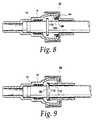
- FIG. 8is a section view of the coupling assembly of FIG. 2 after the insertion verifier dust cap has been attached to the female connector.
- FIG. 9is a section view taken ninety degrees from the coupling assembly of FIG. 8 .
- FIGS. 1 and 2illustrate a coupling assembly of the present invention.
- the coupling assembly 10comprises a male member 12 , a hollow female connector 14 , a retainer 16 , a first O-ring 18 , a first spacer 20 , a second O-ring 22 , a second spacer 24 and an insertion verifier dust cap 26 .
- the male member 12is formed at the end of a hollow and rigid tube 28 which forms a part of a fluid line system.
- the tube 28may lead to a component in a fluid line system, or may itself be a portion of a component in a fluid line system.
- Male member 12includes a radially enlarged annular flange or upset 30 formed at a given distance from the distal end 32 of the male member 12 .
- the female connector body 14is hollow and defines an axial bore 34 extending axially inward from an entrance 36 .
- the entrance 36is defined by a radially inward extending rim 38 having an apex 40 .
- the rim 38is chamfered at the axially outward surface 42 to facilitate the insertion of the male member 12 into the connector body 14 .
- Axially inward from the entrance 36is a first annular face 44 .
- Axially inward from the first annular face 44is a first cylindrical surface 46 and a first conical surface 48 terminating at a second annular face 50 .
- Axially inward from the second annular face 50is a second cylindrical surface 52 terminating at a third annular face 54 .
- Axially inward from the third annular face 54is a third cylindrical surface 56 terminating at a fourth annular face 58 .
- Located at the center of the fourth annular face 58is an entrance to a reduced diameter cylindrical bore 60 forming the fluid line opposite the tube 28 .
- the first annular face 44together with the first cylindrical surface 46 , the first conical surface 48 , the second annular face 50 , the second cylindrical surface 52 , the third annular face 54 , the third cylindrical surface 56 and the fourth annular face 58 , define the axial bore 34 .
- the first O-ring 18 , the first spacer 20 , the second O-ring 22 and the second spacer 24are inserted in the axial bore 34 .
- the first O-ring 18 , the first spacer 20 , the second O-ring 22 and the second spacer 24are situated radially inward of the second cylindrical surface 52 .
- the retainer 16is inserted into the axial bore 34 .
- the retainer 16includes four circumferentially spaced legs 62 which abut the upset 30 of the male member 12 to retain the male member 12 in the axial bore 34 upon full insertion of the male member 12 into the female connector 14 .
- Each leg 62includes a radially inner section 64 which abuts the upset 30 of the male member 12 .
- a bump 66formed on each radially inner section 64 , provides a relatively great force resisting tube insertion.
- Braces 68extend circumferentially from each circumferential side of the radial inner sections 64 to provide additional strength against buckling of the retainer.
- the radially inner section 64includes a lip 70 which abuts the upset 30 of the male member 12 .
- the lip 70is bent radially outwardly such that it contacts the upset 30 over a relatively great surface area.
- a rear bend 72connects the radially inner section 64 with a radially outer section 74 .
- a cylindrical forward ring 76connects the plurality of circumferentially spaced legs 62 . The ring abuts the second annular face 50 and the rear bend abuts the first abutment face 44 to retain the retainer 16 in the axial bore 34 .
- the insertion verifier dust cap 26 of the present inventionis shown in FIGS. 4-7.
- the cap 26is a dual diameter cylindrical shaped shell.
- the cap 26can be opened axially as two shell halves 78 are connected by a hinge 80 on one side.
- the two shell halves 78are snapped together by a rectangular housing 82 formed on the outer surface of one shell and a clasp 84 formed on the outer surface of the other shell.
- the rectangular housing 82has a bore 86 defined therein and a protrusion 88 formed on the radially outer surface of the housing 82 .
- the clasp 84has a U-shaped catch 90 formed at the radially outer surface.
- the U-shaped catch 90has a window 92 in the center for retaining the protrusion 88 .
- Radially inward of the U-shaped catch 90is an outwardly extending pin 94 for insertion into the bore 86 of the housing 82 .
- the two shell halves 78form the dual diameter cylindrical shaped cap 26 .
- the cap 26has a first cylindrical portion 96 having an enlarged diameter and a second cylindrical portion 98 having a reduced diameter.
- the inner diameter D 1 of the first cylindrical portion 96is sized to be at least as large as the outer diameter D 2 of the female connector 14 radially outwardly of the entrance 36 , thus allowing the first cylindrical portion 96 to surround a portion of the connector body 14 radially outward and axially inward of the entrance 36 .
- the first cylindrical portion 96is connected to the second cylindrical portion 98 by an annular portion 100 .
- Formed on the outer surface of the first cylindrical portion 96 and perpendicular to the abutting surfaces of the two shell halves 78are a pair of grooved finger tabs 102 .
- Two circumferentially spaced protruding arms 104are formed on the inner surface of the annular portion 100 of the cap 26 .
- the arms 104extend axially from the annular portion 100 .
- the distal end of each armincludes a hook 106 extending radially outward.
- Each hook 106has an axially inward surface 108 for abutment with the first annular surface 44 of the female connector 14 to retain the cap 26 to the female connector 14 .
- Located axially outward from the axially inward surface 108is a ramped surface 110 to facilitate the insertion of the arms 104 into the female connector 14 .
- Two circumferentially spaced protruding beams 112are formed on the inner surface of the annular portion 100 of the cap 26 ninety degrees from the arms 104 .
- the beams 112extend axially from the annular portion 100 .
- Each beam 112has a terminal surface 114 for abutment with the upset 30 of the male member 12 .
- the coupling assembly 10 of the present inventionfunctions as follows.
- the first O-ring 18 , the first spacer 20 , the second O-ring 22 , the second spacer 24 and the retainer 16are pre-assembled into the female connector 14 .
- the first O-ring 18 , the first spacer 20 , the second O-ring 22 and the second spacer 24are inserted into the axial bore 34 and situated radially inward of the second cylindrical surface 52 .
- the retainer 16is inserted into the axial bore 34 until the ring 76 abuts the second annular face 50 and the rear bend 72 abuts the first abutment face 44 to retain the retainer 16 in the bore 34 .
- the male member 12is then inserted into the female connector 14 .
- the terminal end 32 of the male member 12is inserted through the entrance 36 of the female connector 14 , between the radially inner section 64 of the retainer 16 , through the ring 76 of the retainer 16 , through the second spacer 24 , the second O-ring 22 , the first spacer 20 and the first O-ring 18 , and finally into the portion of the axial bore 34 defined by the third cylindrical surface 56 .
- the first O-ring 18 and the second O-ring 22form a seal between the male member 12 and the axial bore 34 of the female connector 14 .
- the upset 30 of the male member 12then contacts the radially inner section 64 of the retainer 16 .
- the upset 30 of the male member 12Upon further insertion of the male member 12 into the female connector 14 , the upset 30 of the male member 12 applies an axially inward and a radially outward force, pushing the radially inner section 64 radially outward.
- the male member 12is inserted until the upset 30 of the male member 12 surpasses the lip 70 of the radially inner section 64 .
- the radially inner section 64springs radially inward, abutting the upset 30 of the male member 12 , and prevents the male member 12 from withdrawing from the female connector 14 .
- the cap 26is mounted around the tube 28 forming the male member 12 with the first cylindrical portion 96 axially toward the female connector 14 .
- the cap 26is mounted around the tube 28 by placing the inner surface of the second cylindrical portion 98 of one of the shell halves 78 around the tube.
- the other shell half 78then pivots around the hinge 80 to surround the tube 28 .
- the U-shaped catch 90flexes radially outward until the protrusion 88 is situated within the window 92 of the U-shaped catch 90 .
- the U-shaped catch 90then springs radially inward and retains the protrusion 88 within the U-shaped catch 90 .
- the pin 94is inserted into the bore 86 to provide axial and radial stability.
- the cap 26is slid axially toward the female connector 14 .
- the cap 26is rotationally aligned such that the arms 104 and the beams 112 are aligned between the legs 62 of the retainer 16 allowing the arms 104 and the beams 112 to fit between the legs 62 of the retainer 16 .
- the first cylindrical portion 96surrounds at least a portion of female connector 14 radially outward and axially inward of the entrance to prevent contaminants from entering the entrance of the connector body.
- the hooks 106 of the arms 104contact the rim 38 of the female connector 14 and the beams 112 fit between the legs 62 of the retainer 16 . Since at least a portion of the ramped surface 110 has a diameter larger than the apex 40 of the rim 38 , further force applied to the cap 26 in the axial direction causes the arms 104 to flex radially inward such that the diameter of the ramped surface 110 in contact with the rim 38 is the same diameter as the apex 40 of the rim 38 .
- the cap 26is slid axially until the rim 38 surpasses the ramped surface 110 of the hook 106 .
- the arms 104then spring radially outward wherein the axially inward surfaces 108 of the hooks 106 act as abutment surfaces against the first annular face 44 , preventing the cap 26 from withdrawing from the female connector 14 .
- the terminal surfaces 114 of the beams 112abut the upset 30 of the male member 12 , preventing the male member 12 from withdrawing from the female connector 14 .
- the terminal surfaces 114 of the beams 112abut the upset 30 of the male member 12 and push the male member 12 axially inward into the female connector 14 .
- the beams 112 of the cap 26verify that the male member 12 has been properly inserted into the female connector 14 by pushing the upset 30 of the male member 12 axially inward until the male member 12 is properly inserted.
- the cap 26 of the present inventioncan also be used as a release tool to withdraw the male member 12 from the female connector 14 after the male member 12 has been properly inserted into the female connector 14 .
- the cap 26is mounted around the tube 28 forming the male member 12 with the second cylindrical portion 98 axially toward the female connector 14 .
- the cap 26is mounted around the tube 28 by placing the inner surface of the second cylindrical portion 98 of one of the shell halves 78 around the tube 28 .
- the other shell half 78then pivots around the hinge 80 to surround the tube 28 .
- the two shell halve 78are snapped together and the cap 26 is slid axially toward the female connector 14 .
- the outer surface of the second cylindrical portion 98contacts the radially inner sections 64 of the retainer 16 .
- the second cylindrical portion 98pushes the radially inner sections 64 radially outward.
- the cap 26is inserted axially inwardly until the terminal end of the second cylindrical portion 98 contacts the upset 30 of the male member 12 .
- the outer diameter D 3 of the second cylindrical portion 98is sized to at least as large as the diameter D 4 of the upset 30 of the male member 12 .
- the diameter of the radially inner section 64is expanded to be at least as large as the diameter D 4 of the upset 30 of the male member 12 . Thereafter, the upset 30 of the male member 12 is able to fit through the radially inner section 64 and be withdrawn from the female connector 14 .
Landscapes
- Engineering & Computer Science (AREA)
- General Engineering & Computer Science (AREA)
- Mechanical Engineering (AREA)
- Quick-Acting Or Multi-Walled Pipe Joints (AREA)
Abstract
Description
Claims (19)
Priority Applications (1)
| Application Number | Priority Date | Filing Date | Title |
|---|---|---|---|
| US09/966,935US6676171B2 (en) | 1999-11-08 | 2001-09-28 | Insertion verifier dust cap |
Applications Claiming Priority (2)
| Application Number | Priority Date | Filing Date | Title |
|---|---|---|---|
| US09/436,121US6343814B1 (en) | 1999-11-08 | 1999-11-08 | Insertion verifier dust cap |
| US09/966,935US6676171B2 (en) | 1999-11-08 | 2001-09-28 | Insertion verifier dust cap |
Related Parent Applications (1)
| Application Number | Title | Priority Date | Filing Date |
|---|---|---|---|
| US09/436,121ContinuationUS6343814B1 (en) | 1999-11-08 | 1999-11-08 | Insertion verifier dust cap |
Publications (2)
| Publication Number | Publication Date |
|---|---|
| US20030094813A1 US20030094813A1 (en) | 2003-05-22 |
| US6676171B2true US6676171B2 (en) | 2004-01-13 |
Family
ID=23731194
Family Applications (2)
| Application Number | Title | Priority Date | Filing Date |
|---|---|---|---|
| US09/436,121Expired - LifetimeUS6343814B1 (en) | 1999-11-08 | 1999-11-08 | Insertion verifier dust cap |
| US09/966,935Expired - Fee RelatedUS6676171B2 (en) | 1999-11-08 | 2001-09-28 | Insertion verifier dust cap |
Family Applications Before (1)
| Application Number | Title | Priority Date | Filing Date |
|---|---|---|---|
| US09/436,121Expired - LifetimeUS6343814B1 (en) | 1999-11-08 | 1999-11-08 | Insertion verifier dust cap |
Country Status (4)
| Country | Link |
|---|---|
| US (2) | US6343814B1 (en) |
| EP (1) | EP1098127B1 (en) |
| CA (1) | CA2323928A1 (en) |
| DE (1) | DE60027254T2 (en) |
Cited By (9)
| Publication number | Priority date | Publication date | Assignee | Title |
|---|---|---|---|---|
| US20030198510A1 (en)* | 2002-01-08 | 2003-10-23 | Dona-Contero Juan M. | Mounting device |
| US20040066034A1 (en)* | 2002-10-07 | 2004-04-08 | Akira Takayanagi | Connection verifying device and connection verifying structure for a pipe and a connector |
| US20050160866A1 (en)* | 2003-07-18 | 2005-07-28 | Fico Triad S.A. | Mounting element for a bowden cable |
| US20050184518A1 (en)* | 2004-02-19 | 2005-08-25 | Anis Muhammad | Connector assembly for male and female members |
| US20060175831A1 (en)* | 2005-02-10 | 2006-08-10 | Itt Manufacturing Enterprises, Inc. | Fluid quick connect contamination cover |
| US20080168769A1 (en)* | 2007-01-17 | 2008-07-17 | International Engine Intellectual Property Company, Llc | Fluid tube assembly guide |
| US20080309079A1 (en)* | 2005-04-20 | 2008-12-18 | Kongsberg Automotive As | Release Clip |
| US7780201B2 (en) | 2006-10-13 | 2010-08-24 | Medela Holding Ag | Tube connector with three part construction and latching component |
| US8662540B2 (en) | 2011-11-02 | 2014-03-04 | Philip C. Whitener | Quick tube connector |
Families Citing this family (40)
| Publication number | Priority date | Publication date | Assignee | Title |
|---|---|---|---|---|
| US6343814B1 (en)* | 1999-11-08 | 2002-02-05 | Ti Group Automotive Systems, Llc | Insertion verifier dust cap |
| US6543814B2 (en)* | 2000-08-10 | 2003-04-08 | John M. Bartholomew | Quick connector |
| DE20017921U1 (en)* | 2000-10-19 | 2002-02-28 | Armaturenfabrik Hermann Voss GmbH + Co. KG, 51688 Wipperfürth | Connection device for pressure medium pipes |
| DE10126205C1 (en) | 2001-05-30 | 2002-04-04 | Raymond A & Cie | Releasable plug-in coupling, for fluid line e.g. automobile fuel line, has sliding protection sleeve for preventing accidental operation of release pressure plates |
| JP4053409B2 (en)* | 2001-12-06 | 2008-02-27 | シャープ株式会社 | Connector and electronic device having the same |
| DE20201573U1 (en)* | 2002-02-02 | 2003-06-26 | Voss Automotive GmbH, 51688 Wipperfürth | Receiving part of a fluid plug-in coupling |
| US7344166B2 (en)* | 2004-02-05 | 2008-03-18 | Ti Group Automotive Systems, Llc | Quick connector for high pressure applications |
| EP1561990B1 (en)* | 2004-02-05 | 2008-08-20 | TI Group Automotive Systems LLC | Quick connector for high pressure applications |
| DE102004062207B3 (en)* | 2004-12-23 | 2005-10-20 | Kirchner Fraenk Rohr | Connecting device for connecting up pipelines has locking element with first spring arm carrying holding sector |
| DE102005034497A1 (en)* | 2005-07-20 | 2007-02-01 | Ims Connector Systems Gmbh | Connectors and mating connectors |
| US7731245B2 (en)* | 2006-10-06 | 2010-06-08 | Ti Group Automotive Systems, Llc | Quick connector coupling |
| US20080245822A1 (en)* | 2007-04-06 | 2008-10-09 | Timothy James Kennedy | Bottle Capping Systems |
| US7945139B2 (en)* | 2007-06-13 | 2011-05-17 | Corning Cable Systems Llc | Dust cap for fiber optic adapter |
| US20090058084A1 (en)* | 2007-09-05 | 2009-03-05 | Green Ronald D | Adaptor for quick connect coupling in water supply system |
| JP4922126B2 (en)* | 2007-10-18 | 2012-04-25 | 本田技研工業株式会社 | Connector fall-off prevention structure |
| DE112008003868T5 (en)* | 2008-06-12 | 2011-05-05 | Smc Corporation | pipe connectors |
| US8342579B2 (en) | 2009-02-03 | 2013-01-01 | Hennemann Thomas L | Push lock pipe connection system |
| US10221977B2 (en) | 2009-02-03 | 2019-03-05 | Aqseptence Group, Inc. | Pipe coupling |
| US8814219B2 (en)* | 2009-02-03 | 2014-08-26 | Bilfinger Water Technologies, Inc. | Push lock pipe connection system and disconnection tool |
| US9810358B2 (en) | 2009-02-03 | 2017-11-07 | Aqseptence Group, Inc. | Male push lock pipe connection system |
| JP6131183B2 (en) | 2010-05-04 | 2017-05-17 | ノーマ・ユー・エス・ホールディング・リミテッド・ライアビリティ・カンパニーNorma U. S. Holding Llc | Connector assembly |
| JP5708354B2 (en)* | 2011-08-08 | 2015-04-30 | 株式会社アドヴィックス | Coupling device for rotating body connection |
| US9388932B2 (en) | 2012-02-28 | 2016-07-12 | Norma U.S. Holding Llc | Automotive selective catalytic reduction (SCR) system sensor holder and assembly |
| DE102013110478A1 (en)* | 2013-09-23 | 2015-03-26 | Phoenix Contact Gmbh & Co. Kg | Housing device for an electrical terminal and electrical terminal |
| USD717666S1 (en) | 2014-03-14 | 2014-11-18 | The Clorox Company | Fluid dispenser |
| US9068680B1 (en)* | 2014-05-30 | 2015-06-30 | Quick Fitting, Inc. | Push-to-connect fitting integrated packing arrangement, device and methods |
| US10745895B2 (en)* | 2014-09-23 | 2020-08-18 | As America, Inc. | Auto-retracting mechanism for faucet spray head |
| US9989178B2 (en)* | 2015-05-06 | 2018-06-05 | Martinrea Industries, Inc. | Quick connect coupling |
| US9879810B2 (en) | 2015-09-18 | 2018-01-30 | Quick Fitting, Inc. | Push-to-connect joint assembly with protective shield device and method |
| US9562637B1 (en) | 2015-09-22 | 2017-02-07 | Quick Fitting, Inc. | Locking pipe joint assembly, device and method |
| US9857006B2 (en) | 2016-03-31 | 2018-01-02 | Quick Fitting, Inc. | Retaining ring for pipe joint devices |
| US9671049B1 (en) | 2016-07-27 | 2017-06-06 | Quick Fitting, Inc. | Hybrid push-to-connect fitting device and assembly |
| US10400929B2 (en) | 2017-09-27 | 2019-09-03 | Quick Fitting, Inc. | Fitting device, arrangement and method |
| US10962153B2 (en)* | 2018-07-24 | 2021-03-30 | Reliance Worldwide Corporation | Terminal component for plumbing configuration |
| US10969047B1 (en) | 2020-01-29 | 2021-04-06 | Quick Fitting Holding Company, Llc | Electrical conduit fitting and assembly |
| US11035510B1 (en) | 2020-01-31 | 2021-06-15 | Quick Fitting Holding Company, Llc | Electrical conduit fitting and assembly |
| US11105452B1 (en) | 2021-02-25 | 2021-08-31 | Quick Fitting Holding Company, Llc | Push-to-connect joint assembly and device |
| US12305785B2 (en) | 2021-07-28 | 2025-05-20 | Oetiker Ny, Inc. | Fluid connection assembly |
| US12135105B2 (en) | 2022-01-19 | 2024-11-05 | Ka Group Ag | Releasable port connection assembly |
| US20230383879A1 (en)* | 2022-05-24 | 2023-11-30 | RB Distribution, Inc. | Double sided connector |
Citations (11)
| Publication number | Priority date | Publication date | Assignee | Title |
|---|---|---|---|---|
| US4927185A (en)* | 1989-03-07 | 1990-05-22 | Huron Products Corporation | Release tool for fluid quick connectors |
| EP0484690A2 (en) | 1990-10-17 | 1992-05-13 | ITT INDUSTRIES, INC. (a Delaware corporation) | Quick connector |
| US5219188A (en)* | 1991-01-09 | 1993-06-15 | Sanoh Kogyo Kabushiki Kaisha | Construction for preventing incomplete connection of pipes |
| US5303963A (en)* | 1992-03-27 | 1994-04-19 | Bundy Corporation | Tube coupling with secondary retainer clip |
| US5378025A (en)* | 1993-11-03 | 1995-01-03 | Itt Corporation | Quick connector with integral release member |
| US5542717A (en)* | 1994-01-03 | 1996-08-06 | Form Rite, Corporation | Quick connect coupling |
| US5593188A (en) | 1991-09-10 | 1997-01-14 | Bundy Corporation | Quick connect tubing connector and method of assembly |
| US5752726A (en) | 1995-05-03 | 1998-05-19 | Aeroquip Zweigniederlassung Der Trinova Gmbh | Quick-action coupling, in particular for refrigerant lines |
| US6340180B1 (en)* | 1999-01-19 | 2002-01-22 | David M. Wisniewski | Releasable coupling assembly for securing a vehicle fuel line |
| US6343814B1 (en)* | 1999-11-08 | 2002-02-05 | Ti Group Automotive Systems, Llc | Insertion verifier dust cap |
| US6347815B1 (en)* | 1995-08-31 | 2002-02-19 | Cooper Technology Services, Llc | Quick connect fluid coupling with components positioned to provide continuous insertion resistance |
Family Cites Families (6)
| Publication number | Priority date | Publication date | Assignee | Title |
|---|---|---|---|---|
| US2127086A (en)* | 1937-05-20 | 1938-08-16 | Eclipse Machine Co | Hose coupling |
| DE4107603C1 (en)* | 1991-03-09 | 1992-02-06 | Rasmussen Gmbh, 6457 Maintal, De | |
| US5257833A (en)* | 1991-09-25 | 1993-11-02 | Bundy Corporation | Metal retainer for quick connect tubing connector |
| US5228728A (en)* | 1991-12-17 | 1993-07-20 | Huron Products Industries, Inc. | Tube retainer release sleeve |
| US5248168A (en)* | 1992-02-02 | 1993-09-28 | Aeroquip Corporation | Flexible quick disconnect coupling with vibration absorbing member |
| JP2880453B2 (en)* | 1996-06-07 | 1999-04-12 | 三桜工業株式会社 | Retainers for piping fittings |
- 1999
- 1999-11-08USUS09/436,121patent/US6343814B1/ennot_activeExpired - Lifetime
- 2000
- 2000-10-19CACA002323928Apatent/CA2323928A1/ennot_activeAbandoned
- 2000-10-30EPEP00309563Apatent/EP1098127B1/ennot_activeExpired - Lifetime
- 2000-10-30DEDE60027254Tpatent/DE60027254T2/ennot_activeExpired - Lifetime
- 2001
- 2001-09-28USUS09/966,935patent/US6676171B2/ennot_activeExpired - Fee Related
Patent Citations (11)
| Publication number | Priority date | Publication date | Assignee | Title |
|---|---|---|---|---|
| US4927185A (en)* | 1989-03-07 | 1990-05-22 | Huron Products Corporation | Release tool for fluid quick connectors |
| EP0484690A2 (en) | 1990-10-17 | 1992-05-13 | ITT INDUSTRIES, INC. (a Delaware corporation) | Quick connector |
| US5219188A (en)* | 1991-01-09 | 1993-06-15 | Sanoh Kogyo Kabushiki Kaisha | Construction for preventing incomplete connection of pipes |
| US5593188A (en) | 1991-09-10 | 1997-01-14 | Bundy Corporation | Quick connect tubing connector and method of assembly |
| US5303963A (en)* | 1992-03-27 | 1994-04-19 | Bundy Corporation | Tube coupling with secondary retainer clip |
| US5378025A (en)* | 1993-11-03 | 1995-01-03 | Itt Corporation | Quick connector with integral release member |
| US5542717A (en)* | 1994-01-03 | 1996-08-06 | Form Rite, Corporation | Quick connect coupling |
| US5752726A (en) | 1995-05-03 | 1998-05-19 | Aeroquip Zweigniederlassung Der Trinova Gmbh | Quick-action coupling, in particular for refrigerant lines |
| US6347815B1 (en)* | 1995-08-31 | 2002-02-19 | Cooper Technology Services, Llc | Quick connect fluid coupling with components positioned to provide continuous insertion resistance |
| US6340180B1 (en)* | 1999-01-19 | 2002-01-22 | David M. Wisniewski | Releasable coupling assembly for securing a vehicle fuel line |
| US6343814B1 (en)* | 1999-11-08 | 2002-02-05 | Ti Group Automotive Systems, Llc | Insertion verifier dust cap |
Cited By (15)
| Publication number | Priority date | Publication date | Assignee | Title |
|---|---|---|---|---|
| US7093998B2 (en)* | 2002-01-08 | 2006-08-22 | Fico Triad, S.A. | Mounting device |
| US20030198510A1 (en)* | 2002-01-08 | 2003-10-23 | Dona-Contero Juan M. | Mounting device |
| US20040066034A1 (en)* | 2002-10-07 | 2004-04-08 | Akira Takayanagi | Connection verifying device and connection verifying structure for a pipe and a connector |
| US7316428B2 (en)* | 2002-10-07 | 2008-01-08 | Tokai Rubber Industries, Ltd. | Connection verifying device and connection verifying structure for a pipe and a connector |
| US20050160866A1 (en)* | 2003-07-18 | 2005-07-28 | Fico Triad S.A. | Mounting element for a bowden cable |
| US7249788B2 (en)* | 2004-02-19 | 2007-07-31 | Dana Canada Corporation | Connector assembly for male and female members |
| US20050184518A1 (en)* | 2004-02-19 | 2005-08-25 | Anis Muhammad | Connector assembly for male and female members |
| US7866710B2 (en) | 2004-02-19 | 2011-01-11 | Dana Canada Corporation | Two piece quick connect retainer |
| US20060175831A1 (en)* | 2005-02-10 | 2006-08-10 | Itt Manufacturing Enterprises, Inc. | Fluid quick connect contamination cover |
| US20080309079A1 (en)* | 2005-04-20 | 2008-12-18 | Kongsberg Automotive As | Release Clip |
| US9845906B2 (en)* | 2005-04-20 | 2017-12-19 | Kongsberg Automotive As | Release clip |
| US7780201B2 (en) | 2006-10-13 | 2010-08-24 | Medela Holding Ag | Tube connector with three part construction and latching component |
| US8096824B2 (en) | 2006-10-13 | 2012-01-17 | Medela Holding Ag | Tube connector with a latching component to secure a receptacle to a plug |
| US20080168769A1 (en)* | 2007-01-17 | 2008-07-17 | International Engine Intellectual Property Company, Llc | Fluid tube assembly guide |
| US8662540B2 (en) | 2011-11-02 | 2014-03-04 | Philip C. Whitener | Quick tube connector |
Also Published As
| Publication number | Publication date |
|---|---|
| CA2323928A1 (en) | 2001-05-08 |
| EP1098127A1 (en) | 2001-05-09 |
| DE60027254D1 (en) | 2006-05-24 |
| EP1098127B1 (en) | 2006-04-12 |
| US6343814B1 (en) | 2002-02-05 |
| DE60027254T2 (en) | 2007-01-11 |
| US20030094813A1 (en) | 2003-05-22 |
Similar Documents
| Publication | Publication Date | Title |
|---|---|---|
| US6676171B2 (en) | Insertion verifier dust cap | |
| US5628531A (en) | Quick connector with secondary latch | |
| US5725258A (en) | Fluid quick connector | |
| US7467813B2 (en) | Quick connector | |
| US5586792A (en) | Quick connector with integral release mechanism | |
| US8282139B2 (en) | Quick connector with seal assembly retainer | |
| US7891380B2 (en) | Protective cap for quick connector | |
| US6543814B2 (en) | Quick connector | |
| US6173994B1 (en) | Coupling assemblies for providing fluid connection | |
| US6086118A (en) | Quick connect tubing connector | |
| US5538297A (en) | Quick connect tubing connector | |
| US5275448A (en) | Quick connect tubing connector and method of assembly | |
| US20060170211A1 (en) | Quick connector | |
| US6497433B1 (en) | Coupling assemblies for providing fluid connection | |
| JPH08178143A (en) | Quick connector fitting for visual connection confirmation | |
| US6412826B1 (en) | High pressure quick connector | |
| CN213871595U (en) | Quick connector for connecting a male connector and a flexible pipe | |
| CN112096991B (en) | Quick connector for connecting male connectors and flexible pipes | |
| US6179341B1 (en) | Quick connect retainer having tolerance for wide band of male tube dimensions | |
| EP1724511B1 (en) | Quick connector with a retainer | |
| JPH10252965A (en) | Connector and retainer |
Legal Events
| Date | Code | Title | Description |
|---|---|---|---|
| AS | Assignment | Owner name:TI GROUP AUTOMOTIVE SYSTEMS, LLC, MICHIGAN Free format text:MERGER;ASSIGNOR:TI GROUP AUTOMOTIVE SYSTEMS CORPORATION;REEL/FRAME:012407/0436 Effective date:20010625 | |
| FPAY | Fee payment | Year of fee payment:4 | |
| AS | Assignment | Owner name:JPMORGAN CHASE BANK, N.A., NEW YORK Free format text:SECURITY AGREEMENT;ASSIGNORS:HANIL USA, L.L.C.;TI AUTOMOTIVE, L.L.C.;TI GROUP AUTOMOTIVE SYSTEMS, L.L.C.;REEL/FRAME:019733/0933 Effective date:20070629 Owner name:JPMORGAN CHASE BANK, N.A.,NEW YORK Free format text:SECURITY AGREEMENT;ASSIGNORS:HANIL USA, L.L.C.;TI AUTOMOTIVE, L.L.C.;TI GROUP AUTOMOTIVE SYSTEMS, L.L.C.;REEL/FRAME:019733/0933 Effective date:20070629 | |
| AS | Assignment | Owner name:WILMINGTON TRUST (LONDON) LIMITED,UNITED KINGDOM Free format text:ASSIGNMENT OF SECURITY INTEREST;ASSIGNOR:JP MORGAN CHASE BANK, N.A.;REEL/FRAME:024055/0633 Effective date:20100208 Owner name:WILMINGTON TRUST (LONDON) LIMITED, UNITED KINGDOM Free format text:ASSIGNMENT OF SECURITY INTEREST;ASSIGNOR:JP MORGAN CHASE BANK, N.A.;REEL/FRAME:024055/0633 Effective date:20100208 | |
| AS | Assignment | Owner name:HANIL USA, L.L.C., MICHIGAN Free format text:RELEASE AND TERMINATION OF PATENT SECURITY INTEREST;ASSIGNOR:WILMINGTON TRUST (LONDON) LIMITED (AS SUCCESSOR IN INTEREST TO JP MORGAN CHASE BANK, N.A.);REEL/FRAME:024891/0671 Effective date:20100825 Owner name:CITIBANK N.A., DELAWARE Free format text:ABL PATENT SECURITY AGREEMENT;ASSIGNOR:TI GROUP AUTOMOTIVE SYSTEMS, L.L.C.;REEL/FRAME:024895/0956 Effective date:20100825 Owner name:TI AUTOMOTIVE, L.L.C., MICHIGAN Free format text:RELEASE AND TERMINATION OF PATENT SECURITY INTEREST;ASSIGNOR:WILMINGTON TRUST (LONDON) LIMITED (AS SUCCESSOR IN INTEREST TO JP MORGAN CHASE BANK, N.A.);REEL/FRAME:024891/0671 Effective date:20100825 Owner name:CITIBANK N.A., DELAWARE Free format text:TERM PATENT SECURITY AGREEMENT;ASSIGNOR:TI GROUP AUTOMOTIVE SYSTEMS, L.L.C.;REEL/FRAME:024896/0057 Effective date:20100825 Owner name:TI GROUP AUTOMOTIVE SYSTEMS, L.L.C., MICHIGAN Free format text:RELEASE AND TERMINATION OF PATENT SECURITY INTEREST;ASSIGNOR:WILMINGTON TRUST (LONDON) LIMITED (AS SUCCESSOR IN INTEREST TO JP MORGAN CHASE BANK, N.A.);REEL/FRAME:024891/0671 Effective date:20100825 | |
| FPAY | Fee payment | Year of fee payment:8 | |
| AS | Assignment | Owner name:TI GROUP AUTOMOTIVE SYSTEMS, L.L.C., MICHIGAN Free format text:RELEASE BY SECURED PARTY;ASSIGNOR:CITIBANK, N.A.;REEL/FRAME:027865/0016 Effective date:20120314 Owner name:JPMORGAN CHASE BANK, N.A., NEW YORK Free format text:SECURITY AGREEMENT;ASSIGNORS:TI GROUP AUTOMOTIVE SYSTEMS, L.L.C.;TI AUTOMOTIVE LIMITED;TI AUTOMOTIVE CANADA, INC.;AND OTHERS;REEL/FRAME:027864/0968 Effective date:20120314 | |
| AS | Assignment | Owner name:TI AUTOMOTIVE CANADA, INC., CANADA Free format text:TERMINATION AND RELEASE;ASSIGNOR:JPMORGAN CHASE BANK, N.A., AS ADMINISTRATIVE AGENT;REEL/FRAME:036013/0775 Effective date:20150630 Owner name:TI AUTOMOTIVE, L.L.C., MICHIGAN Free format text:TERMINATION AND RELEASE;ASSIGNOR:JPMORGAN CHASE BANK, N.A., AS ADMINISTRATIVE AGENT;REEL/FRAME:036013/0775 Effective date:20150630 Owner name:TI GROUP AUTOMOTIVE SYSTEMS S DE R.L. DE C.V., MEX Free format text:TERMINATION AND RELEASE;ASSIGNOR:JPMORGAN CHASE BANK, N.A., AS ADMINISTRATIVE AGENT;REEL/FRAME:036013/0775 Effective date:20150630 Owner name:TI GROUP AUTOMOTIVE SYSTEMS, L.L.C., MICHIGAN Free format text:TERMINATION AND RELEASE;ASSIGNOR:JPMORGAN CHASE BANK, N.A., AS ADMINISTRATIVE AGENT;REEL/FRAME:036013/0775 Effective date:20150630 Owner name:HANIL USA L.L.C., ALABAMA Free format text:TERMINATION AND RELEASE;ASSIGNOR:JPMORGAN CHASE BANK, N.A., AS ADMINISTRATIVE AGENT;REEL/FRAME:036013/0775 Effective date:20150630 Owner name:TI AUTOMOTIVE LIMITED, UNITED KINGDOM Free format text:TERMINATION AND RELEASE;ASSIGNOR:JPMORGAN CHASE BANK, N.A., AS ADMINISTRATIVE AGENT;REEL/FRAME:036013/0775 Effective date:20150630 Owner name:JPMORGAN CHASE BANK, N.A., AS THE COLLATERAL AGENT Free format text:SECURITY AGREEMENT;ASSIGNORS:TI GROUP AUTOMOTIVE SYSTEMS, L.L.C.;HANIL USA, L.L.C.;TI AUTOMOTIVE, L.L.C.;REEL/FRAME:036013/0666 Effective date:20150630 | |
| REMI | Maintenance fee reminder mailed | ||
| LAPS | Lapse for failure to pay maintenance fees | ||
| STCH | Information on status: patent discontinuation | Free format text:PATENT EXPIRED DUE TO NONPAYMENT OF MAINTENANCE FEES UNDER 37 CFR 1.362 | |
| FP | Lapsed due to failure to pay maintenance fee | Effective date:20160113 | |
| AS | Assignment | Owner name:MILLENIUM INDUSTRIES CORPORATION, MICHIGAN Free format text:RELEASE OF SECURITY INTEREST (REEL 036013, FRAME 0666);ASSIGNOR:JPMORGAN CHASE BANK, N.A., AS COLLATERAL AGENT;REEL/FRAME:070917/0957 Effective date:20250422 Owner name:TI AUTOMOTIVE, L.L.C., MICHIGAN Free format text:RELEASE OF SECURITY INTEREST (REEL 036013, FRAME 0666);ASSIGNOR:JPMORGAN CHASE BANK, N.A., AS COLLATERAL AGENT;REEL/FRAME:070917/0957 Effective date:20250422 Owner name:HANIL USA, L.L.C., ALABAMA Free format text:RELEASE OF SECURITY INTEREST (REEL 036013, FRAME 0666);ASSIGNOR:JPMORGAN CHASE BANK, N.A., AS COLLATERAL AGENT;REEL/FRAME:070917/0957 Effective date:20250422 Owner name:TI GROUP AUTOMOTIVE SYSTEMS, L.L.C., MICHIGAN Free format text:RELEASE OF SECURITY INTEREST (REEL 036013, FRAME 0666);ASSIGNOR:JPMORGAN CHASE BANK, N.A., AS COLLATERAL AGENT;REEL/FRAME:070917/0957 Effective date:20250422 |