US6676104B2 - Device for controlling the flow of liquid using a tube - Google Patents
Device for controlling the flow of liquid using a tubeDownload PDFInfo
- Publication number
- US6676104B2 US6676104B2US10/299,275US29927502AUS6676104B2US 6676104 B2US6676104 B2US 6676104B2US 29927502 AUS29927502 AUS 29927502AUS 6676104 B2US6676104 B2US 6676104B2
- Authority
- US
- United States
- Prior art keywords
- tube
- flow
- shaped surface
- arc shaped
- shortening
- Prior art date
- Legal status (The legal status is an assumption and is not a legal conclusion. Google has not performed a legal analysis and makes no representation as to the accuracy of the status listed.)
- Expired - Fee Related
Links
Images

Classifications
- F—MECHANICAL ENGINEERING; LIGHTING; HEATING; WEAPONS; BLASTING
- F16—ENGINEERING ELEMENTS AND UNITS; GENERAL MEASURES FOR PRODUCING AND MAINTAINING EFFECTIVE FUNCTIONING OF MACHINES OR INSTALLATIONS; THERMAL INSULATION IN GENERAL
- F16K—VALVES; TAPS; COCKS; ACTUATING-FLOATS; DEVICES FOR VENTING OR AERATING
- F16K7/00—Diaphragm valves or cut-off apparatus, e.g. with a member deformed, but not moved bodily, to close the passage ; Pinch valves
- F16K7/02—Diaphragm valves or cut-off apparatus, e.g. with a member deformed, but not moved bodily, to close the passage ; Pinch valves with tubular diaphragm
- A—HUMAN NECESSITIES
- A61—MEDICAL OR VETERINARY SCIENCE; HYGIENE
- A61M—DEVICES FOR INTRODUCING MEDIA INTO, OR ONTO, THE BODY; DEVICES FOR TRANSDUCING BODY MEDIA OR FOR TAKING MEDIA FROM THE BODY; DEVICES FOR PRODUCING OR ENDING SLEEP OR STUPOR
- A61M5/00—Devices for bringing media into the body in a subcutaneous, intra-vascular or intramuscular way; Accessories therefor, e.g. filling or cleaning devices, arm-rests
- A61M5/14—Infusion devices, e.g. infusing by gravity; Blood infusion; Accessories therefor
- A61M5/168—Means for controlling media flow to the body or for metering media to the body, e.g. drip meters, counters ; Monitoring media flow to the body
- A61M5/16804—Flow controllers
- A61M5/16813—Flow controllers by controlling the degree of opening of the flow line
- F—MECHANICAL ENGINEERING; LIGHTING; HEATING; WEAPONS; BLASTING
- F16—ENGINEERING ELEMENTS AND UNITS; GENERAL MEASURES FOR PRODUCING AND MAINTAINING EFFECTIVE FUNCTIONING OF MACHINES OR INSTALLATIONS; THERMAL INSULATION IN GENERAL
- F16K—VALVES; TAPS; COCKS; ACTUATING-FLOATS; DEVICES FOR VENTING OR AERATING
- F16K7/00—Diaphragm valves or cut-off apparatus, e.g. with a member deformed, but not moved bodily, to close the passage ; Pinch valves
- F16K7/02—Diaphragm valves or cut-off apparatus, e.g. with a member deformed, but not moved bodily, to close the passage ; Pinch valves with tubular diaphragm
- F16K7/08—Diaphragm valves or cut-off apparatus, e.g. with a member deformed, but not moved bodily, to close the passage ; Pinch valves with tubular diaphragm constrictable by twisting
Definitions
- the present inventionrelates to a device with an elastic tube for a varied flow through said tube, whereby the device comprises a tube being fixed at its two ends.
- the object of the present inventionis to obtain a device with an elastic tube by means of which device a predetermined, varied and controllable flow through the tube, can be obtained.
- peristaltic pumpsin particular for pumping small volumes, which pumps comprise a tube arranged on the inside of a circular house against which tube a number of rolls are arranged to act rotatably and by means of their rotation press a liquid through the tube.
- the flow volume through the tubeis dependent on the rotational speed of the rolls against the tube.
- valve devices at infusion tubesfor regulating the flow through the tube. It has, however, turned out that these valves do not provide a constant flow and do not provide reproducible flows.
- the flowcan be varied in a very efficient and accurate way which is particularly essential at infusions where great demands for a constant flow is due, in order not to e.g., overdosing at a drug infusion.
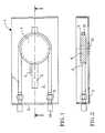
- FIG. 1shows a device according to the invention seen from above
- FIG. 2the device of FIG. 1 seen in a cross-sectional view along the line II—II.
- the 1denotes in general a house which in its bottom part 2 is provided with a track 3 .
- a wheel 4movably arranged.
- Position markings 5are further arranged along the track 3 .
- the wheel 4is suitably provided with an arcuate recess 6 in which a tube 7 is arranged to be introduced.
- the tube 7which is suitably a silicone polymer tube, is at its two ends releasably attached to two nipples 8 arranged in the short end side 9 of the house 1 .
- the nipples 8are provided with through-going holes (not shown) for communicating with nipples 10 arranged on the outside of the house 1 , which nipples are arranged to be connected to a liquid container and e.g., a patient, respectively, via a tube (not shown). Underneath the wheel 4 in the track 3 there is a screw 11 arranged for the fixation of the wheel 4 in a desired position.
- the tube 7When the wheel 4 is moved along the track 3 the tube 7 is strained and is stretched due to its elastic properties. Simultaneous with the stretching, the lumen 12 of the tube 7 will be reduced as well, which conclusively means that the flow will become down-regulated from a first less stretched condition to a second more stretched condition.
- V tk ⁇ ⁇ ⁇ ⁇ p ⁇ D 4 l
- the formulameans that the flow is reciprocally proportional to the length of the tube but proportional to the fourth power of the diameter of the tube.
- the diameter of the tubethus plays a dominating role and at small liquid flows and, particularly at liquids comprising particles, such as blood, which is commonly present in medical situations, it is thus difficult to control the flow only by means of changing the diameter of the tube.
- the changebecomes exponential and extremely small changes of the diameter of the tube provides great changes of the liquid flow which is evident from the attached graph.
- the changed of the length of the tubeprovides a more even change of the flow but is hard to carry out from a practical point of view. A simultaneous change of the length of the tube and diameter will thus become more optimal.
Landscapes
- Engineering & Computer Science (AREA)
- General Engineering & Computer Science (AREA)
- Health & Medical Sciences (AREA)
- Mechanical Engineering (AREA)
- Biomedical Technology (AREA)
- Veterinary Medicine (AREA)
- Hematology (AREA)
- Life Sciences & Earth Sciences (AREA)
- Animal Behavior & Ethology (AREA)
- General Health & Medical Sciences (AREA)
- Public Health (AREA)
- Heart & Thoracic Surgery (AREA)
- Anesthesiology (AREA)
- Vascular Medicine (AREA)
- Infusion, Injection, And Reservoir Apparatuses (AREA)
- Reciprocating Pumps (AREA)
- External Artificial Organs (AREA)
- Sampling And Sample Adjustment (AREA)
- Catching Or Destruction (AREA)
Abstract
Description
This is a continuation of PCT/SE01/01138, filed May 21, 2001.
1. Technical Field
The present invention relates to a device with an elastic tube for a varied flow through said tube, whereby the device comprises a tube being fixed at its two ends.
The object of the present invention is to obtain a device with an elastic tube by means of which device a predetermined, varied and controllable flow through the tube, can be obtained.
2. Background of the Invention
It is previously known different peristaltic pumps, in particular for pumping small volumes, which pumps comprise a tube arranged on the inside of a circular house against which tube a number of rolls are arranged to act rotatably and by means of their rotation press a liquid through the tube. The flow volume through the tube is dependent on the rotational speed of the rolls against the tube.
It is further known valve devices at infusion tubes for regulating the flow through the tube. It has, however, turned out that these valves do not provide a constant flow and do not provide reproducible flows.
It has now surprisingly turned out possible to be able to obtain a reproducible, varied and controllable flow by means of the present invention which is characterized in that the tube is arranged to be stretched by means of a longing of the distance between its points of attachment.
Further characteristics are evident from the accompanying claims.
By means of the present invention it is obtained that the flow can be varied in a very efficient and accurate way which is particularly essential at infusions where great demands for a constant flow is due, in order not to e.g., overdosing at a drug infusion.
The present invention will now be described more in detail with reference to the attached drawing, which shows a preferred embodiment, however, without being restricted hereto. In the drawing
FIG. 1 shows a device according to the invention seen from above; and
FIG. 2 the device of FIG. 1 seen in a cross-sectional view along the line II—II.
1 denotes in general a house which in itsbottom part 2 is provided with atrack 3. In thetrack 3 there is awheel 4 movably arranged.Position markings 5 are further arranged along thetrack 3. Thewheel 4 is suitably provided with an arcuate recess6 in which atube 7 is arranged to be introduced. Thetube 7 which is suitably a silicone polymer tube, is at its two ends releasably attached to twonipples 8 arranged in theshort end side 9 of the house1. Thenipples 8 are provided with through-going holes (not shown) for communicating withnipples 10 arranged on the outside of the house1, which nipples are arranged to be connected to a liquid container and e.g., a patient, respectively, via a tube (not shown). Underneath thewheel 4 in thetrack 3 there is ascrew 11 arranged for the fixation of thewheel 4 in a desired position.
When thewheel 4 is moved along thetrack 3 thetube 7 is strained and is stretched due to its elastic properties. Simultaneous with the stretching, thelumen 12 of thetube 7 will be reduced as well, which conclusively means that the flow will become down-regulated from a first less stretched condition to a second more stretched condition.

V=volume
t=time
Δp=pressure fall between the ends of the tube
D4=forth potence of the diameter of the lumen of the tube
l=the length of the tube
k=π/128η, wherein η is the dynamic viscosity of the liquid
The formula means that the flow is reciprocally proportional to the length of the tube but proportional to the fourth power of the diameter of the tube. The diameter of the tube thus plays a dominating role and at small liquid flows and, particularly at liquids comprising particles, such as blood, which is commonly present in medical situations, it is thus difficult to control the flow only by means of changing the diameter of the tube. The change becomes exponential and extremely small changes of the diameter of the tube provides great changes of the liquid flow which is evident from the attached graph. The changed of the length of the tube provides a more even change of the flow but is hard to carry out from a practical point of view. A simultaneous change of the length of the tube and diameter will thus become more optimal.
By successively straining an elastic tube, one will simultaneously obtain, together with a longing of the tube, a narrowing of the lumen which provides an optimal and almost linear control of the liquid flow.
In the trial given below an elastic tube being 180 mm long and having a lumen of 0.5 mm. The pressure fall was 0.1 mbar. Each step in the following flow table means a longing of 8 mm.
| TABLE | |||
| Change of length | Flow | ||
| from 180 mm | ml/hr | ||
| 0 | 420 | ||
| 2 | 390 | ||
| 4 | 360 | ||
| 6 | 330 | ||
| 8 | 300 | ||
| 10 | 270 | ||
| 12 | 240 | ||
| 14 | 210 | ||
| 16 | 180 | ||
| 18 | 150 | ||
| 20 | 120 | ||
| 22 | 90 | ||
| 24 | 60 | ||
As evident from the results provided an almost linear change of the flow amount is obtained which means an assumption for an exact dosage of the flow at small flow amounts without using a compulsory pump function with the drawbacks this leads to.
By adopting the length of the tube, the wall thickness of the tube, the lumen diameter, and the elastic construction to get a widespread utilization.
Claims (6)
1. A device containing a tube for a varied flow, comprising a tube being fixed at its both ends,
wherein the tube is arranged to be stretched or shortened by lengthening or shortening of the length of the tube between said fixed points, whereby the device comprises at least one arc shaped surface arranged to receive said tube, that the arc shaped surface is arranged to be adjustably moved in a longitudinal direction for longing or shortening said tube, and whereby the arc shaped surface is at least one wheel provided with a radially inwardly directed recess for receiving said tube.
2. A device according toclaim 1 , wherein the tube is an infusion tube.
3. A device according toclaim 1 , wherein the tube is of an elastic material.
4. A device according toclaim 3 , wherein the tube is a silicone material tube.
5. A device according toclaim 1 , wherein the tube is arranged in a system to control the flow through the same.
6. A process for controlling a flow through a tube, wherein one stretches or relaxes an elastic tube between two attachment points via at least one arc shaped surface arranged to receive said tube, the arc shaped surface being arranged to be adjustably moved in a longitudinal direction for lengthening or shortening said tube, and whereby the arc shaped surface is at least one wheel provided with a radially inwardly directed recess for receiving said tube, for on one hand lengthening or shortening said tube, on the other hand narrowing or widening its lumen.
Applications Claiming Priority (4)
| Application Number | Priority Date | Filing Date | Title |
|---|---|---|---|
| SE0001852ASE524080C2 (en) | 2000-05-19 | 2000-05-19 | Device with hose |
| SE0001852 | 2000-05-19 | ||
| SE0001852-3 | 2000-05-19 | ||
| PCT/SE2001/001138WO2001089609A1 (en) | 2000-05-19 | 2001-05-21 | Device for controlling the flow of liquid using a tube |
Related Parent Applications (1)
| Application Number | Title | Priority Date | Filing Date |
|---|---|---|---|
| PCT/SE2001/001138ContinuationWO2001089609A1 (en) | 2000-05-19 | 2001-05-21 | Device for controlling the flow of liquid using a tube |
Publications (2)
| Publication Number | Publication Date |
|---|---|
| US20030116730A1 US20030116730A1 (en) | 2003-06-26 |
| US6676104B2true US6676104B2 (en) | 2004-01-13 |
Family
ID=20279735
Family Applications (1)
| Application Number | Title | Priority Date | Filing Date |
|---|---|---|---|
| US10/299,275Expired - Fee RelatedUS6676104B2 (en) | 2000-05-19 | 2002-11-19 | Device for controlling the flow of liquid using a tube |
Country Status (11)
| Country | Link |
|---|---|
| US (1) | US6676104B2 (en) |
| EP (1) | EP1284759B1 (en) |
| JP (1) | JP2003534060A (en) |
| CN (1) | CN1232312C (en) |
| AT (1) | ATE280598T1 (en) |
| AU (1) | AU2001260925A1 (en) |
| CA (1) | CA2409822A1 (en) |
| DE (1) | DE60106752T2 (en) |
| ES (1) | ES2233638T3 (en) |
| SE (1) | SE524080C2 (en) |
| WO (1) | WO2001089609A1 (en) |
Cited By (11)
| Publication number | Priority date | Publication date | Assignee | Title |
|---|---|---|---|---|
| US20060178632A1 (en)* | 2000-10-18 | 2006-08-10 | Trombley Frederick W Iii | Injector system with a manual control device |
| US20070005044A1 (en)* | 2005-05-10 | 2007-01-04 | Palion Medical Corporation | Implantable pump with infinitely variable resistor |
| US20070112328A1 (en)* | 2005-05-10 | 2007-05-17 | Palyon Medical Corporation | Variable flow infusion pump system |
| US20090112164A1 (en)* | 2007-10-30 | 2009-04-30 | Medrad, Inc. | System and method for proportional mixing and continuous delivery of fluids |
| US8114055B2 (en) | 2005-05-10 | 2012-02-14 | Palyon Medical (Bvi) Limited | Implantable pump with infinitely variable resistor |
| US8568360B2 (en) | 2011-12-28 | 2013-10-29 | Palyon Medical (Bvi) Limited | Programmable implantable pump design |
| US8915893B2 (en) | 2005-05-10 | 2014-12-23 | Palyon Medical (Bvi) Limited | Variable flow infusion pump system |
| US9011377B2 (en) | 2008-11-05 | 2015-04-21 | Bayer Medical Care Inc. | Fluid mixing control device for a multi-fluid delivery system |
| US9433730B2 (en) | 2013-03-14 | 2016-09-06 | Bayer Healthcare Llc | Fluid mixing control device for a multi-fluid delivery system |
| US9649436B2 (en) | 2011-09-21 | 2017-05-16 | Bayer Healthcare Llc | Assembly method for a fluid pump device for a continuous multi-fluid delivery system |
| US10507319B2 (en) | 2015-01-09 | 2019-12-17 | Bayer Healthcare Llc | Multiple fluid delivery system with multi-use disposable set and features thereof |
Families Citing this family (7)
| Publication number | Priority date | Publication date | Assignee | Title |
|---|---|---|---|---|
| US7392085B2 (en)* | 2001-11-21 | 2008-06-24 | Cameron Health, Inc. | Multiple electrode vectors for implantable cardiac treatment devices |
| JP4986687B2 (en)* | 2007-04-05 | 2012-07-25 | アサヒビール株式会社 | Fluid stopper device |
| KR101851378B1 (en)* | 2010-10-01 | 2018-04-23 | 제벡스, 아이엔씨. | Method for improving accuracy in a peristaltic pump system based on tubing material properties |
| IN2014CN03498A (en) | 2011-11-08 | 2015-10-09 | Koninkl Philips Nv | |
| CN110960747B (en)* | 2019-12-19 | 2021-08-06 | 山东大学齐鲁医院 | A kind of high precision analgesia pump and working method |
| CN110975058B (en)* | 2019-12-19 | 2021-08-10 | 齐鲁理工学院 | Automatically-adjustable analgesia pump and working method |
| CN110898290B (en)* | 2019-12-31 | 2021-07-30 | 山东大学齐鲁医院 | A kind of multifunctional portable infusion device and working method |
Citations (5)
| Publication number | Priority date | Publication date | Assignee | Title |
|---|---|---|---|---|
| US3773034A (en)* | 1971-11-24 | 1973-11-20 | Itt Research Institute | Steerable catheter |
| EP0045668A1 (en) | 1980-08-06 | 1982-02-10 | Peter Steer Developments Limited | Device for controlling the flow of liquid |
| US4478434A (en)* | 1982-10-14 | 1984-10-23 | Little Gerald R | Hose mender device |
| US4671320A (en) | 1985-07-19 | 1987-06-09 | Victor Grifols Lucas | Adjustable valve for liquids for equipment having a medical application |
| US5913861A (en)* | 1996-03-12 | 1999-06-22 | Cordis Corp | Method of catheter balloon manufacture and use |
- 2000
- 2000-05-19SESE0001852Apatent/SE524080C2/ennot_activeIP Right Cessation
- 2001
- 2001-05-21CNCNB018097189Apatent/CN1232312C/ennot_activeExpired - Fee Related
- 2001-05-21EPEP01934773Apatent/EP1284759B1/ennot_activeExpired - Lifetime
- 2001-05-21WOPCT/SE2001/001138patent/WO2001089609A1/enactiveIP Right Grant
- 2001-05-21AUAU2001260925Apatent/AU2001260925A1/ennot_activeAbandoned
- 2001-05-21JPJP2001585849Apatent/JP2003534060A/enactivePending
- 2001-05-21ESES01934773Tpatent/ES2233638T3/ennot_activeExpired - Lifetime
- 2001-05-21CACA002409822Apatent/CA2409822A1/ennot_activeAbandoned
- 2001-05-21ATAT01934773Tpatent/ATE280598T1/ennot_activeIP Right Cessation
- 2001-05-21DEDE60106752Tpatent/DE60106752T2/ennot_activeExpired - Fee Related
- 2002
- 2002-11-19USUS10/299,275patent/US6676104B2/ennot_activeExpired - Fee Related
Patent Citations (5)
| Publication number | Priority date | Publication date | Assignee | Title |
|---|---|---|---|---|
| US3773034A (en)* | 1971-11-24 | 1973-11-20 | Itt Research Institute | Steerable catheter |
| EP0045668A1 (en) | 1980-08-06 | 1982-02-10 | Peter Steer Developments Limited | Device for controlling the flow of liquid |
| US4478434A (en)* | 1982-10-14 | 1984-10-23 | Little Gerald R | Hose mender device |
| US4671320A (en) | 1985-07-19 | 1987-06-09 | Victor Grifols Lucas | Adjustable valve for liquids for equipment having a medical application |
| US5913861A (en)* | 1996-03-12 | 1999-06-22 | Cordis Corp | Method of catheter balloon manufacture and use |
Cited By (29)
| Publication number | Priority date | Publication date | Assignee | Title |
|---|---|---|---|---|
| US9764081B2 (en) | 2000-10-18 | 2017-09-19 | Bayer Healthcare Llc | Fluid path containing a pressure isolation valve |
| US9833559B2 (en) | 2000-10-18 | 2017-12-05 | Bayer Healthcare Llc | Pressure isolation mechanisms, method of use thereof and fluid delivery systems including pressure isolation mechanisms |
| US20060178632A1 (en)* | 2000-10-18 | 2006-08-10 | Trombley Frederick W Iii | Injector system with a manual control device |
| US8747358B2 (en) | 2000-10-18 | 2014-06-10 | Bayer Medical Care Inc. | Injector system with a manual control device |
| US20070005044A1 (en)* | 2005-05-10 | 2007-01-04 | Palion Medical Corporation | Implantable pump with infinitely variable resistor |
| US20070112328A1 (en)* | 2005-05-10 | 2007-05-17 | Palyon Medical Corporation | Variable flow infusion pump system |
| US7637892B2 (en) | 2005-05-10 | 2009-12-29 | Palyon Medical (Bvi) Limited | Variable flow infusion pump system |
| US20100069892A1 (en)* | 2005-05-10 | 2010-03-18 | Palyon Medical (Bvi) Limited | Variable flow infusion pump system |
| US8591478B2 (en) | 2005-05-10 | 2013-11-26 | Palyon Medical (Bvi) Limited | Reduced size implantable pump |
| US8114055B2 (en) | 2005-05-10 | 2012-02-14 | Palyon Medical (Bvi) Limited | Implantable pump with infinitely variable resistor |
| US8915893B2 (en) | 2005-05-10 | 2014-12-23 | Palyon Medical (Bvi) Limited | Variable flow infusion pump system |
| US8177750B2 (en) | 2005-05-10 | 2012-05-15 | Palyon Medical (Bvi) Limited | Variable flow infusion pump system |
| US8211060B2 (en) | 2005-05-10 | 2012-07-03 | Palyon Medical (Bvi) Limited | Reduced size implantable pump |
| US20100298699A1 (en)* | 2007-10-30 | 2010-11-25 | Medrad Inc. | System and Method for Proportional Mixing and Continuous Delivery of Fluids |
| USRE45717E1 (en) | 2007-10-30 | 2015-10-06 | Bayer Medical Care Inc. | System and method for proportional mixing and continuous delivery of fluids |
| US8162903B2 (en) | 2007-10-30 | 2012-04-24 | Medrad, Inc. | System and method for proportional mixing and continuous delivery of fluids |
| US20090112164A1 (en)* | 2007-10-30 | 2009-04-30 | Medrad, Inc. | System and method for proportional mixing and continuous delivery of fluids |
| US7766883B2 (en) | 2007-10-30 | 2010-08-03 | Medrad, Inc. | System and method for proportional mixing and continuous delivery of fluids |
| US9011377B2 (en) | 2008-11-05 | 2015-04-21 | Bayer Medical Care Inc. | Fluid mixing control device for a multi-fluid delivery system |
| US9861742B2 (en) | 2008-11-05 | 2018-01-09 | Bayer Healthcare Llc | Fluid mixing control device for a multi-fluid delivery system |
| US10441716B2 (en) | 2008-11-05 | 2019-10-15 | Bayer Healthcare Llc | Fluid mixing control device for a multi-fluid delivery system |
| US9649436B2 (en) | 2011-09-21 | 2017-05-16 | Bayer Healthcare Llc | Assembly method for a fluid pump device for a continuous multi-fluid delivery system |
| US9700672B2 (en) | 2011-09-21 | 2017-07-11 | Bayer Healthcare Llc | Continuous multi-fluid pump device, drive and actuating system and method |
| US8568360B2 (en) | 2011-12-28 | 2013-10-29 | Palyon Medical (Bvi) Limited | Programmable implantable pump design |
| US8961466B2 (en) | 2011-12-28 | 2015-02-24 | Palyon Medical (Bvi) Limited | Programmable implantable pump design |
| US9433730B2 (en) | 2013-03-14 | 2016-09-06 | Bayer Healthcare Llc | Fluid mixing control device for a multi-fluid delivery system |
| US10507319B2 (en) | 2015-01-09 | 2019-12-17 | Bayer Healthcare Llc | Multiple fluid delivery system with multi-use disposable set and features thereof |
| US11491318B2 (en) | 2015-01-09 | 2022-11-08 | Bayer Healthcare Llc | Multiple fluid delivery system with multi-use disposable set and features thereof |
| US12201802B2 (en) | 2015-01-09 | 2025-01-21 | Bayer Healthcare Llc | Multiple fluid delivery system with multi-use disposable set and features thereof |
Also Published As
| Publication number | Publication date |
|---|---|
| AU2001260925A1 (en) | 2001-12-03 |
| EP1284759A1 (en) | 2003-02-26 |
| JP2003534060A (en) | 2003-11-18 |
| CN1441682A (en) | 2003-09-10 |
| CA2409822A1 (en) | 2001-11-29 |
| CN1232312C (en) | 2005-12-21 |
| DE60106752D1 (en) | 2004-12-02 |
| SE0001852L (en) | 2001-11-20 |
| EP1284759B1 (en) | 2004-10-27 |
| SE0001852D0 (en) | 2000-05-19 |
| US20030116730A1 (en) | 2003-06-26 |
| SE524080C2 (en) | 2004-06-22 |
| ATE280598T1 (en) | 2004-11-15 |
| DE60106752T2 (en) | 2006-02-16 |
| WO2001089609A1 (en) | 2001-11-29 |
| ES2233638T3 (en) | 2005-06-16 |
Similar Documents
| Publication | Publication Date | Title |
|---|---|---|
| US6676104B2 (en) | Device for controlling the flow of liquid using a tube | |
| US3298367A (en) | Apparatus for administering parenteral liquids | |
| US5586872A (en) | Adjustable peristaltic pump | |
| AU607124B2 (en) | Open patient fluid management method and system | |
| KR101397276B1 (en) | Flow controller | |
| JP4658190B2 (en) | Medical fluid delivery apparatus and method | |
| US6036668A (en) | Process and device for the conveyance and measuring of medical liquids | |
| US5304153A (en) | Apparatus and system for the self-dosing of a liquid medicine | |
| WO2004011056A2 (en) | Syringe pump | |
| DE2951286A1 (en) | INFUSION DEVICE | |
| US6929236B1 (en) | Apparatus for flow rate control | |
| EP2964092B1 (en) | Pressure-measuring system and method for automatic deaeration and zero-setting | |
| CA2058944A1 (en) | Fluid delivery apparatus | |
| KR20090010019A (en) | Flow Control Dosing Set | |
| EP1964584A3 (en) | Positive pressure infusion system having downstream resistance measurement capability | |
| ATE309013T1 (en) | DEVICE FOR COMPENSATING PRESSURE DIFFERENCES BETWEEN VALVES IN TYPE IV PUMPS | |
| WO1997047339A1 (en) | Gravity infusion set for medical infusions | |
| US7985198B2 (en) | Device and process for metering solutions | |
| EP0479957B1 (en) | Vacuum infusion device | |
| KR20020062644A (en) | Pressure-responsive flow regulator and drug delivery devices employing the same | |
| EP1135179B1 (en) | Flow regulator | |
| WO1987004785A1 (en) | Liquid metering device | |
| DE1911919A1 (en) | Dosing pump | |
| WO2021105981A1 (en) | Fluid pump | |
| CN101603920B (en) | Linear micro-starting pump suitable for chemiluminescence determinator |
Legal Events
| Date | Code | Title | Description |
|---|---|---|---|
| AS | Assignment | Owner name:PREMETEC AB, SWEDEN Free format text:ASSIGNMENT OF ASSIGNORS INTEREST;ASSIGNOR:TILLANDER, HANS;REEL/FRAME:013760/0504 Effective date:20030115 | |
| FEPP | Fee payment procedure | Free format text:PAT HOLDER CLAIMS SMALL ENTITY STATUS, ENTITY STATUS SET TO SMALL (ORIGINAL EVENT CODE: LTOS); ENTITY STATUS OF PATENT OWNER: SMALL ENTITY | |
| FPAY | Fee payment | Year of fee payment:4 | |
| REMI | Maintenance fee reminder mailed | ||
| LAPS | Lapse for failure to pay maintenance fees | ||
| STCH | Information on status: patent discontinuation | Free format text:PATENT EXPIRED DUE TO NONPAYMENT OF MAINTENANCE FEES UNDER 37 CFR 1.362 | |
| FP | Lapsed due to failure to pay maintenance fee | Effective date:20120113 |