US6675779B2 - Dual float valve for fuel tank vent with liquid carryover filter - Google Patents
Dual float valve for fuel tank vent with liquid carryover filterDownload PDFInfo
- Publication number
- US6675779B2 US6675779B2US10/170,603US17060302AUS6675779B2US 6675779 B2US6675779 B2US 6675779B2US 17060302 AUS17060302 AUS 17060302AUS 6675779 B2US6675779 B2US 6675779B2
- Authority
- US
- United States
- Prior art keywords
- valve
- housing
- fuel
- communicating
- fuel tank
- Prior art date
- Legal status (The legal status is an assumption and is not a legal conclusion. Google has not performed a legal analysis and makes no representation as to the accuracy of the status listed.)
- Ceased
Links
- 239000002828fuel tankSubstances0.000titleclaimsabstractdescription68
- 239000007788liquidSubstances0.000titleclaimsabstractdescription56
- 230000009977dual effectEffects0.000title1
- 239000000446fuelSubstances0.000claimsabstractdescription125
- 238000013022ventingMethods0.000claimsabstractdescription71
- 238000011084recoveryMethods0.000claimsdescription35
- 230000000717retained effectEffects0.000claimsdescription16
- 230000000903blocking effectEffects0.000claimsdescription2
- 239000000945fillerSubstances0.000abstractdescription12
- 238000009423ventilationMethods0.000abstractdescription4
- 238000007789sealingMethods0.000description11
- 230000000712assemblyEffects0.000description6
- 238000000429assemblyMethods0.000description6
- 238000002485combustion reactionMethods0.000description4
- 239000000463materialSubstances0.000description4
- 210000002445nippleAnatomy0.000description4
- 238000012360testing methodMethods0.000description4
- 238000009825accumulationMethods0.000description3
- 238000010276constructionMethods0.000description3
- 238000013461designMethods0.000description3
- 238000000926separation methodMethods0.000description3
- 239000004215Carbon black (E152)Substances0.000description2
- 238000007667floatingMethods0.000description2
- 229930195733hydrocarbonNatural products0.000description2
- 150000002430hydrocarbonsChemical class0.000description2
- 238000009434installationMethods0.000description2
- 230000000750progressive effectEffects0.000description2
- 238000010926purgeMethods0.000description2
- 230000000630rising effectEffects0.000description2
- 244000025254Cannabis sativaSpecies0.000description1
- 230000003213activating effectEffects0.000description1
- 230000002411adverseEffects0.000description1
- 239000003610charcoalSubstances0.000description1
- 238000011109contaminationMethods0.000description1
- 238000001816coolingMethods0.000description1
- 230000000694effectsEffects0.000description1
- 239000012530fluidSubstances0.000description1
- 238000010438heat treatmentMethods0.000description1
- 238000012423maintenanceMethods0.000description1
- 230000007246mechanismEffects0.000description1
- 239000002184metalSubstances0.000description1
- 238000000034methodMethods0.000description1
- 238000012986modificationMethods0.000description1
- 230000004048modificationEffects0.000description1
- 230000007935neutral effectEffects0.000description1
- 239000002245particleSubstances0.000description1
- 230000004044responseEffects0.000description1
- 230000004043responsivenessEffects0.000description1
- 229920006395saturated elastomerPolymers0.000description1
- 238000003466weldingMethods0.000description1
Images


Classifications
- F—MECHANICAL ENGINEERING; LIGHTING; HEATING; WEAPONS; BLASTING
- F02—COMBUSTION ENGINES; HOT-GAS OR COMBUSTION-PRODUCT ENGINE PLANTS
- F02M—SUPPLYING COMBUSTION ENGINES IN GENERAL WITH COMBUSTIBLE MIXTURES OR CONSTITUENTS THEREOF
- F02M37/00—Apparatus or systems for feeding liquid fuel from storage containers to carburettors or fuel-injection apparatus; Arrangements for purifying liquid fuel specially adapted for, or arranged on, internal-combustion engines
- F02M37/20—Apparatus or systems for feeding liquid fuel from storage containers to carburettors or fuel-injection apparatus; Arrangements for purifying liquid fuel specially adapted for, or arranged on, internal-combustion engines characterised by means for preventing vapour lock
- F—MECHANICAL ENGINEERING; LIGHTING; HEATING; WEAPONS; BLASTING
- F02—COMBUSTION ENGINES; HOT-GAS OR COMBUSTION-PRODUCT ENGINE PLANTS
- F02M—SUPPLYING COMBUSTION ENGINES IN GENERAL WITH COMBUSTIBLE MIXTURES OR CONSTITUENTS THEREOF
- F02M25/00—Engine-pertinent apparatus for adding non-fuel substances or small quantities of secondary fuel to combustion-air, main fuel or fuel-air mixture
- F02M25/08—Engine-pertinent apparatus for adding non-fuel substances or small quantities of secondary fuel to combustion-air, main fuel or fuel-air mixture adding fuel vapours drawn from engine fuel reservoir
- F02M25/0836—Arrangement of valves controlling the admission of fuel vapour to an engine, e.g. valve being disposed between fuel tank or absorption canister and intake manifold
Definitions
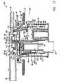
- FIG. 14is a diagrammatic illustration similar to that as shown in FIGS. 5-13 and in which a fill nozzle protection system has failed resulting in fuel flowing through a signal line and into the tank venting apparatus yet blocking flow to the canister;
- vaporflows from the valve 10 through the line 32 coupled to the filler neck 14 and returns to the fuel tank 12 .
- vaporcan flow from the valve 10 to the vapor recovery canister 30 for controlled purging and combustion during the combustion cycle of the engine.
- FIG. 8continued dispensing of fuel 20 into the tank 12 causes the float 92 to rise upwardly causing the seal 100 to seal against the opening 53 .
- increased pressure in an open area 148 of the tankwill cause the fuel dispensing system to shut off by preventing further dispensing of fuel into the tank.
- further venting of vaporswill not occur through the venting control valve 10 .
- thisallows an onboard fuel maintenance computer system, of known construction, carried on the vehicle to manage the accumulation of fuel vapor in the canister to efficiently burn the vapors from the canister periodically.
- Thisalso prevents surges which generally cannot be accommodated by the onboard computer.
- the onboard computertypically cannot react fast enough to a surge and as such preventing surges helps to improve the efficiency and life of the vapor recovery system.
- Closing of the chamber 61prevents the flow of liquid fuel through the canister line 34 and thereby prevents contamination of the canister with liquid fuel.
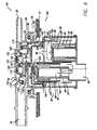
- the third valve assembly 44is also referred to as a liquid/separation or liquid discriminator valve, or an overlying valve.
- the cup-like form of the valve 71captures a portion of atmosphere within the tank causing it to be buoyant within the chamber 61 . Buoyancy forces the nipple 152 into the opening 63 thereby closing or sealing the opening.
- FIG. 13shows the venting control system or venting control valve 10 in a condition in which an onboard diagnostics system of known construction carried on the vehicle applies a vacuum to the fuel system to sense leaks.
- the onboard diagnostics systemis coupled to the vehicle fuel level gauge to determine whether the conditions are suitable to conduct a leak test. For example, when the tank is at 85% capacity, the onboard diagnostics system may conduct a leak test. When these conditions are met, the onboard diagnostics system will operate a vacuum pump to create a vacuum or draw a vacuum on the fuel tank. The system can also operate using a pressure to detect leaks. Further, the system can utilize natural forces vacuum or pressure which can be developed naturally in the tank as a result of heating and cooling of fuel in the tank.
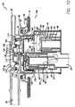
- FIG. 14shows a condition which creates a response in the valve 10 which is similar to that shown in FIG. 12 .
- FIG. 14illustrates a condition in which the fuel dispensing nozzle 18 (see FIG. 1) may have failed.
- fuelflows through the signal line 32 to the fourth valve assembly 46 .
- the diaphragm 110closes or seals as a result of accumulation of liquid fuel within an upper portion 153 of a fourth valve chamber 155 .
- the diaphragm seal portion 118seals against the sealing surface 120 . As such, fuel is prevented from flowing into the canister passage 34 and to the canister 30 .
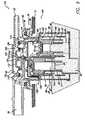
- FIG. 16shows another condition which should be considered for proper operation of venting control systems and valves 10 .
- FIG. 16shows a condition when a vehicle vapor recovery system is drawing vapors from the canister 30 for combustion. Under these circumstances a slight vacuum is drawn through the system which will tend to promote the removal of vapors from the tank 12 . As such, vapors are allowed to flow through the system 10 . Similar to the conditions as described above with regard to FIG. 13, vapors will be allowed to freely flow to the system 10 through the canister passage 34 to the canister 30 .
- the dimension of the passage 63restricts the flow of vapors thereby facilitating a generally consistent flow of vapors to promote clean burning of the vapors from the canister as well as those vapors flowing through the system as the canister is purged.
Landscapes
- Engineering & Computer Science (AREA)
- Chemical & Material Sciences (AREA)
- Combustion & Propulsion (AREA)
- Mechanical Engineering (AREA)
- General Engineering & Computer Science (AREA)
- Cooling, Air Intake And Gas Exhaust, And Fuel Tank Arrangements In Propulsion Units (AREA)
- Supplying Secondary Fuel Or The Like To Fuel, Air Or Fuel-Air Mixtures (AREA)
Abstract
Description
Claims (21)
Priority Applications (1)
| Application Number | Priority Date | Filing Date | Title |
|---|---|---|---|
| US10/170,603US6675779B2 (en) | 2002-06-13 | 2002-06-13 | Dual float valve for fuel tank vent with liquid carryover filter |
Applications Claiming Priority (1)
| Application Number | Priority Date | Filing Date | Title |
|---|---|---|---|
| US10/170,603US6675779B2 (en) | 2002-06-13 | 2002-06-13 | Dual float valve for fuel tank vent with liquid carryover filter |
Publications (2)
| Publication Number | Publication Date |
|---|---|
| US20030230288A1 US20030230288A1 (en) | 2003-12-18 |
| US6675779B2true US6675779B2 (en) | 2004-01-13 |
Family
ID=29732538
Family Applications (1)
| Application Number | Title | Priority Date | Filing Date |
|---|---|---|---|
| US10/170,603CeasedUS6675779B2 (en) | 2002-06-13 | 2002-06-13 | Dual float valve for fuel tank vent with liquid carryover filter |
Country Status (1)
| Country | Link |
|---|---|
| US (1) | US6675779B2 (en) |
Cited By (60)
| Publication number | Priority date | Publication date | Assignee | Title |
|---|---|---|---|---|
| US20050022898A1 (en)* | 2003-08-01 | 2005-02-03 | Williamson Brian J. | Fuel tank vent system |
| US20060037642A1 (en)* | 2004-08-23 | 2006-02-23 | Vladimir Olshanetsky | Dual function valve for fuel tank |
| US20060100506A1 (en)* | 1998-11-04 | 2006-05-11 | Johns Hopkins University School Of Medicine | System and method for magnetic-resonance-guided electrophysiologic and ablation procedures |
| US20060247684A1 (en)* | 2001-04-13 | 2006-11-02 | Greatbatch-Sierra, Inc. | Band stop filter employing a capacitor and an inductor tank circuit to enhance mri compatibility of active medical devices |
| US20070079872A1 (en)* | 2005-10-07 | 2007-04-12 | Alfmeier Corporation | Vent valve assembly with lever arrangement |
| US20070088416A1 (en)* | 2001-04-13 | 2007-04-19 | Surgi-Vision, Inc. | Mri compatible medical leads |
| US20070112398A1 (en)* | 2005-11-11 | 2007-05-17 | Greatbatch Ltd. | Tank filters placed in series with the lead wires or circuits of active medical devices to enhance mri compatibility |
| US20070123949A1 (en)* | 2005-11-11 | 2007-05-31 | Greatbatch Ltd. | Low loss band pass filter for rf distance telemetry pin antennas of active implantable medical devices |
| US20070193561A1 (en)* | 2006-02-13 | 2007-08-23 | Eaton Corporation | Double shut-off refueling valve |
| US20070289633A1 (en)* | 2006-06-07 | 2007-12-20 | Eaton Corporation | On-Board refueling vapor recovery system with vent line check valve |
| US7318576B2 (en) | 2004-05-27 | 2008-01-15 | Alfmeier Prazision Ag Baugruppen Und Systemlosungen | Bi-directional air valve for a tank system of a motor vehicle |
| US20080049376A1 (en)* | 1998-11-04 | 2008-02-28 | Greatbatch Ltd. | Non-ferromagnetic tank filters in lead wires of active implantable medical devices to enhance mri compatibility |
| US20080065181A1 (en)* | 2001-04-13 | 2008-03-13 | Greatbatch, Ltd. | Rfid detection and identification system for implantable medical lead systems |
| US20080071313A1 (en)* | 2005-11-11 | 2008-03-20 | Greatbatch Ltd. | Tank filters utilizing very low k materials, in series with lead wires or circuits of active medical devices to enhance mri compatibility |
| US20080116997A1 (en)* | 2001-04-13 | 2008-05-22 | Greatbatch Ltd. | Cylindrical bandstop filters for medical lead systems |
| US20080132987A1 (en)* | 2001-04-13 | 2008-06-05 | Greatbatch Ltd. | Medical lead system utilizing electromagnetic bandstop filters |
| US20080161886A1 (en)* | 2006-06-08 | 2008-07-03 | Greatbatch Ltd. | Tank filters adaptable for placement with a guide wire, in series with the lead wires or circuits of active medical devices to enhance mri compatibility |
| US20080195180A1 (en)* | 2006-06-08 | 2008-08-14 | Greatbatch Ltd. | Low loss band pass filter for rf distance telemetry pin antennas of active implantable medical devices |
| US20090116167A1 (en)* | 2002-02-28 | 2009-05-07 | Greatbatch Ltd. | Passive electronic network components designed for direct body fluid exposure |
| US20090194170A1 (en)* | 2008-02-01 | 2009-08-06 | Eaton Corporation | Multi-function control valve for fuel vapor system |
| US20090293849A1 (en)* | 2008-05-28 | 2009-12-03 | Toyoda Gosei Co., Ltd. | Venting device for fuel tank |
| US20100100164A1 (en)* | 2006-11-09 | 2010-04-22 | Greatbatch Ltd. | Capacitor and inductor elements physically disposed in series whose lumped parameters are electrically connected in parallel to form a bandstop filter |
| US20100160997A1 (en)* | 2001-04-13 | 2010-06-24 | Greatbatch Ltd. | Tuned energy balanced system for minimizing heating and/or to provide emi protection of implanted leads in a high power electromagnetic field environment |
| US20100168821A1 (en)* | 2001-04-13 | 2010-07-01 | Greatbatch Ltd. | Switched diverter circuits for minimizing heating of an implanted lead in a high power electromagnetic field environment |
| US20100191236A1 (en)* | 2001-04-13 | 2010-07-29 | Greatbatch Ltd. | Switched diverter circuits for minimizing heating of an implanted lead and/or providing emi protection in a high power electromagnetic field environment |
| US20100208397A1 (en)* | 2008-12-17 | 2010-08-19 | Greatbatch Ltd. | Switched safety protection circuit for an aimd system during exposure to high power electromagnetic fields |
| US20100217262A1 (en)* | 2001-04-13 | 2010-08-26 | Greatbatch Ltd. | Frequency selective passive component networks for active implantable medical devices utilizing an energy dissipating surface |
| US20100218748A1 (en)* | 2006-01-26 | 2010-09-02 | Inergy Automotive Systems Research (S.A.) | Device for the Venting Circuit of a Liquid Tank and Valve Incorporating Said Device |
| EP2357017A1 (en) | 2010-02-17 | 2011-08-17 | Greatbatch Ltd. | Emi filter employing a capacitor and an inductor tank circuit having optimum component values |
| US20110213233A1 (en)* | 2006-06-08 | 2011-09-01 | Greatbatch Ltd. | Tank filters placed in series with the lead wires or circuits of active medical devices to enhance mri compatibility |
| USRE42856E1 (en) | 2002-05-29 | 2011-10-18 | MRI Interventions, Inc. | Magnetic resonance probes |
| EP2392382A1 (en) | 2005-11-11 | 2011-12-07 | Greatbatch Ltd. | Tank filters placed in series with the lead wires or circuits of active medical devices to enhance MRI compatibility |
| US20120037638A1 (en)* | 2009-04-23 | 2012-02-16 | Inergy Automotive Systems Research (Societe Anonyme) | Plastic fuel tank with improved creep resistance and method for the manufacture thereof |
| US8224462B2 (en) | 2005-11-11 | 2012-07-17 | Greatbatch Ltd. | Medical lead system utilizing electromagnetic bandstop filters |
| US20120305555A1 (en)* | 2010-01-07 | 2012-12-06 | Kautex Textron Gmbh & Co. Kg | Drop separator |
| US8712544B2 (en) | 2001-04-13 | 2014-04-29 | Greatbatch Ltd. | Electromagnetic shield for a passive electronic component in an active medical device implantable lead |
| US20140158216A1 (en)* | 2011-12-22 | 2014-06-12 | Eaton Corporation | Fuel tank vent valve assembly and method of assembly |
| US20140209190A1 (en)* | 2013-01-30 | 2014-07-31 | Toyoda Gosei Co., Ltd. | Fuel tank valve |
| US8903505B2 (en) | 2006-06-08 | 2014-12-02 | Greatbatch Ltd. | Implantable lead bandstop filter employing an inductive coil with parasitic capacitance to enhance MRI compatibility of active medical devices |
| US9031670B2 (en) | 2006-11-09 | 2015-05-12 | Greatbatch Ltd. | Electromagnetic shield for a passive electronic component in an active medical device implantable lead |
| US9108066B2 (en) | 2008-03-20 | 2015-08-18 | Greatbatch Ltd. | Low impedance oxide resistant grounded capacitor for an AIMD |
| US9248283B2 (en) | 2001-04-13 | 2016-02-02 | Greatbatch Ltd. | Band stop filter comprising an inductive component disposed in a lead wire in series with an electrode |
| KR20160029483A (en)* | 2014-09-05 | 2016-03-15 | 현대중공업 주식회사 | Ventilation valve for hydrogen gas seperation chamberof ballast water treatment system |
| US9295828B2 (en) | 2001-04-13 | 2016-03-29 | Greatbatch Ltd. | Self-resonant inductor wound portion of an implantable lead for enhanced MRI compatibility of active implantable medical devices |
| DE102005017138B4 (en)* | 2004-04-14 | 2016-08-18 | Nifco Inc. | Valve for a fuel tank |
| US9427596B2 (en) | 2013-01-16 | 2016-08-30 | Greatbatch Ltd. | Low impedance oxide resistant grounded capacitor for an AIMD |
| US9428043B2 (en) | 2013-11-07 | 2016-08-30 | Fca Us Llc | Liquid vapor separator drain valve |
| US9468750B2 (en) | 2006-11-09 | 2016-10-18 | Greatbatch Ltd. | Multilayer planar spiral inductor filter for medical therapeutic or diagnostic applications |
| KR20160136329A (en)* | 2014-03-05 | 2016-11-29 | 가부시키가이샤 파이오락꾸스 | Vlave device for fuel tank |
| USRE46699E1 (en) | 2013-01-16 | 2018-02-06 | Greatbatch Ltd. | Low impedance oxide resistant grounded capacitor for an AIMD |
| US9931514B2 (en) | 2013-06-30 | 2018-04-03 | Greatbatch Ltd. | Low impedance oxide resistant grounded capacitor for an AIMD |
| US10080889B2 (en) | 2009-03-19 | 2018-09-25 | Greatbatch Ltd. | Low inductance and low resistance hermetically sealed filtered feedthrough for an AIMD |
| US20190210453A1 (en)* | 2016-08-18 | 2019-07-11 | Nifco Korea Inc. | Fill limit vent valve for fuel tank |
| US10350421B2 (en) | 2013-06-30 | 2019-07-16 | Greatbatch Ltd. | Metallurgically bonded gold pocket pad for grounding an EMI filter to a hermetic terminal for an active implantable medical device |
| US10559409B2 (en) | 2017-01-06 | 2020-02-11 | Greatbatch Ltd. | Process for manufacturing a leadless feedthrough for an active implantable medical device |
| US10561837B2 (en) | 2011-03-01 | 2020-02-18 | Greatbatch Ltd. | Low equivalent series resistance RF filter for an active implantable medical device utilizing a ceramic reinforced metal composite filled via |
| US10589107B2 (en) | 2016-11-08 | 2020-03-17 | Greatbatch Ltd. | Circuit board mounted filtered feedthrough assembly having a composite conductive lead for an AIMD |
| US10905888B2 (en) | 2018-03-22 | 2021-02-02 | Greatbatch Ltd. | Electrical connection for an AIMD EMI filter utilizing an anisotropic conductive layer |
| US10912945B2 (en) | 2018-03-22 | 2021-02-09 | Greatbatch Ltd. | Hermetic terminal for an active implantable medical device having a feedthrough capacitor partially overhanging a ferrule for high effective capacitance area |
| US11198014B2 (en) | 2011-03-01 | 2021-12-14 | Greatbatch Ltd. | Hermetically sealed filtered feedthrough assembly having a capacitor with an oxide resistant electrical connection to an active implantable medical device housing |
Families Citing this family (14)
| Publication number | Priority date | Publication date | Assignee | Title |
|---|---|---|---|---|
| DE10238237A1 (en)* | 2002-08-21 | 2004-03-04 | Daimlerchrysler Ag | Motor vehicle fuel tank has feed pipe for catch pot also forming feed pipe for suction pump |
| DE102004022564A1 (en)* | 2004-05-07 | 2005-12-01 | Siemens Ag | Fuel supply device for a motor vehicle |
| JP4415888B2 (en)* | 2005-03-22 | 2010-02-17 | 豊田合成株式会社 | Fuel shut-off valve |
| US20080041348A1 (en)* | 2006-04-12 | 2008-02-21 | Grant Jeffrey P | Fuel tank with integrated evaporative emissions system |
| US8459237B2 (en)* | 2010-02-11 | 2013-06-11 | Eaton Corporation | Fill head assembly having membrane for protecting recirculation line |
| DE102010055310A1 (en)* | 2010-12-21 | 2012-06-21 | Audi Ag | Fuel system and method of operating a fuel system |
| CN103477135B (en)* | 2011-01-31 | 2016-01-06 | 拉瓦尔农业合作社有限公司 | Fuel valve |
| WO2015127477A1 (en)* | 2014-02-24 | 2015-08-27 | Eaton Corporation | Fuel tank liquid vapor discriminator with integrated over-pressure and make-up air valves |
| CN105904962A (en)* | 2016-05-20 | 2016-08-31 | 斯丹德汽车系统(苏州)有限公司 | Fuel oil liquid level valve device |
| CN106917701A (en)* | 2017-04-20 | 2017-07-04 | 苏州欧迪科汽车设计有限公司 | A kind of multifunctional control valve |
| US10792697B2 (en)* | 2017-05-17 | 2020-10-06 | Taiwan Semiconductor Manufacturing Company, Ltd. | Drippage prevention system and method of operating same |
| DE112018007962T5 (en)* | 2018-09-06 | 2021-06-02 | Honda Motor Co., Ltd. | Working machine |
| JP7188307B2 (en)* | 2019-07-23 | 2022-12-13 | 豊田合成株式会社 | fuel shutoff valve |
| CN114320673A (en)* | 2020-10-09 | 2022-04-12 | 通用汽车环球科技运作有限责任公司 | Evaporative emission system |
Citations (30)
| Publication number | Priority date | Publication date | Assignee | Title |
|---|---|---|---|---|
| US4790349A (en) | 1988-04-04 | 1988-12-13 | Stant Inc. | Tank pressure control system |
| US4953583A (en) | 1989-03-24 | 1990-09-04 | Stant Inc. | Tank pressure control valve |
| US4966189A (en) | 1989-10-24 | 1990-10-30 | Stant Inc. | Tank valve mounting assembly |
| US4991615A (en) | 1990-03-02 | 1991-02-12 | Stant Inc. | Tank pressure control apparatus |
| US5028244A (en) | 1990-06-27 | 1991-07-02 | Stant Inc. | Tank venting control valve assembly |
| US5065782A (en) | 1991-01-08 | 1991-11-19 | Stant Inc. | Tank venting control assembly |
| US5116257A (en) | 1991-01-08 | 1992-05-26 | Stant Inc. | Tank venting control assembly |
| US5156178A (en) | 1991-02-22 | 1992-10-20 | Stant Inc. | Vacuum-actuated vent assembly |
| US5234013A (en) | 1992-07-07 | 1993-08-10 | Stant Manufacturing Inc. | Tank venting control assembly |
| US5234022A (en) | 1992-10-09 | 1993-08-10 | Stant Manufacturing Inc. | Flow control valve |
| US5261439A (en) | 1991-02-22 | 1993-11-16 | Stant Manufacturing Inc. | Vacuum-actuated vent assembly |
| US5318069A (en) | 1992-01-17 | 1994-06-07 | Stant Manufacturing Inc. | Tank venting and vapor recovery system |
| US5443561A (en) | 1993-04-09 | 1995-08-22 | Honda Giken Kogyo Kabushiki Kaisha | Fuel vapor discharge limiting device for fuel tank |
| US5449018A (en) | 1994-01-04 | 1995-09-12 | Stant Manufacturing Inc. | Flow control valve |
| US5449029A (en) | 1994-05-11 | 1995-09-12 | Stant Manufacturing Inc. | Fill limit valve assembly |
| US5518018A (en)* | 1994-11-14 | 1996-05-21 | Stant Manufacturing Inc. | Fuel tank venting control assembly |
| US5535772A (en) | 1995-05-01 | 1996-07-16 | Stant Manufacturing Inc. | Tank venting control system |
| US5566705A (en) | 1995-06-30 | 1996-10-22 | Stant Manufacturing Inc. | Snap-closure float valve assembly |
| US5687778A (en) | 1995-05-01 | 1997-11-18 | Stant Manufacturing Inc. | Dual valve tank venting system |
| US5694968A (en) | 1996-04-15 | 1997-12-09 | Stant Manufacturing Inc. | Tank venting control system |
| US5797434A (en)* | 1994-08-24 | 1998-08-25 | G.T. Products, Inc. | Onboard vapor recovery system with two-stage shutoff valve |
| US5944044A (en) | 1996-05-10 | 1999-08-31 | Stant Manufacturing Inc. | Tank venting control system |
| US6003499A (en) | 1998-01-07 | 1999-12-21 | Stant Manufacturing Inc. | Tank vent control apparatus |
| US6016827A (en) | 1998-12-21 | 2000-01-25 | Daimlerchrysler Corporation | Control valve for onboard refueling vapor recovery fuel system |
| US6035884A (en) | 1997-09-16 | 2000-03-14 | Stant Manufacturing Inc. | Liquid fuel baffle for vent apparatus |
| US6240950B1 (en) | 1998-08-27 | 2001-06-05 | Stant Manufacturing Inc. | Vapor control valve with bypass circuit |
| US6311675B2 (en) | 1999-04-28 | 2001-11-06 | Walbro Corporation | Vent valve and fuel pump module |
| US6405747B1 (en) | 1999-10-29 | 2002-06-18 | Stant Manufacturing, Inc. | Fuel tank vent valve with liquid carryover filter |
| US6422261B1 (en) | 2000-02-03 | 2002-07-23 | Stant Manufacturing Inc. | Weldable mount for fuel system component |
| US6431200B2 (en) | 2000-02-11 | 2002-08-13 | Stant Manufacturing Inc. | Weldable mount for fuel system component |
- 2002
- 2002-06-13USUS10/170,603patent/US6675779B2/ennot_activeCeased
Patent Citations (32)
| Publication number | Priority date | Publication date | Assignee | Title |
|---|---|---|---|---|
| US4790349A (en) | 1988-04-04 | 1988-12-13 | Stant Inc. | Tank pressure control system |
| US4953583A (en) | 1989-03-24 | 1990-09-04 | Stant Inc. | Tank pressure control valve |
| US4966189A (en) | 1989-10-24 | 1990-10-30 | Stant Inc. | Tank valve mounting assembly |
| US4991615A (en) | 1990-03-02 | 1991-02-12 | Stant Inc. | Tank pressure control apparatus |
| US5028244A (en) | 1990-06-27 | 1991-07-02 | Stant Inc. | Tank venting control valve assembly |
| US5065782A (en) | 1991-01-08 | 1991-11-19 | Stant Inc. | Tank venting control assembly |
| US5116257A (en) | 1991-01-08 | 1992-05-26 | Stant Inc. | Tank venting control assembly |
| US5261439A (en) | 1991-02-22 | 1993-11-16 | Stant Manufacturing Inc. | Vacuum-actuated vent assembly |
| US5156178A (en) | 1991-02-22 | 1992-10-20 | Stant Inc. | Vacuum-actuated vent assembly |
| US5388611A (en) | 1992-01-17 | 1995-02-14 | Stant Manufacturing Inc. | Tank venting and vapor recovery system |
| US5318069A (en) | 1992-01-17 | 1994-06-07 | Stant Manufacturing Inc. | Tank venting and vapor recovery system |
| US5234013A (en) | 1992-07-07 | 1993-08-10 | Stant Manufacturing Inc. | Tank venting control assembly |
| US5234022A (en) | 1992-10-09 | 1993-08-10 | Stant Manufacturing Inc. | Flow control valve |
| US5443561A (en) | 1993-04-09 | 1995-08-22 | Honda Giken Kogyo Kabushiki Kaisha | Fuel vapor discharge limiting device for fuel tank |
| US5449018A (en) | 1994-01-04 | 1995-09-12 | Stant Manufacturing Inc. | Flow control valve |
| US5449029A (en) | 1994-05-11 | 1995-09-12 | Stant Manufacturing Inc. | Fill limit valve assembly |
| US5797434A (en)* | 1994-08-24 | 1998-08-25 | G.T. Products, Inc. | Onboard vapor recovery system with two-stage shutoff valve |
| US5518018A (en)* | 1994-11-14 | 1996-05-21 | Stant Manufacturing Inc. | Fuel tank venting control assembly |
| US5687778A (en) | 1995-05-01 | 1997-11-18 | Stant Manufacturing Inc. | Dual valve tank venting system |
| US5535772A (en) | 1995-05-01 | 1996-07-16 | Stant Manufacturing Inc. | Tank venting control system |
| US5566705A (en) | 1995-06-30 | 1996-10-22 | Stant Manufacturing Inc. | Snap-closure float valve assembly |
| US5694968A (en) | 1996-04-15 | 1997-12-09 | Stant Manufacturing Inc. | Tank venting control system |
| US5944044A (en) | 1996-05-10 | 1999-08-31 | Stant Manufacturing Inc. | Tank venting control system |
| US6170510B1 (en) | 1997-05-06 | 2001-01-09 | Stant Manufacturing Inc. | Tank venting control system |
| US6035884A (en) | 1997-09-16 | 2000-03-14 | Stant Manufacturing Inc. | Liquid fuel baffle for vent apparatus |
| US6003499A (en) | 1998-01-07 | 1999-12-21 | Stant Manufacturing Inc. | Tank vent control apparatus |
| US6240950B1 (en) | 1998-08-27 | 2001-06-05 | Stant Manufacturing Inc. | Vapor control valve with bypass circuit |
| US6016827A (en) | 1998-12-21 | 2000-01-25 | Daimlerchrysler Corporation | Control valve for onboard refueling vapor recovery fuel system |
| US6311675B2 (en) | 1999-04-28 | 2001-11-06 | Walbro Corporation | Vent valve and fuel pump module |
| US6405747B1 (en) | 1999-10-29 | 2002-06-18 | Stant Manufacturing, Inc. | Fuel tank vent valve with liquid carryover filter |
| US6422261B1 (en) | 2000-02-03 | 2002-07-23 | Stant Manufacturing Inc. | Weldable mount for fuel system component |
| US6431200B2 (en) | 2000-02-11 | 2002-08-13 | Stant Manufacturing Inc. | Weldable mount for fuel system component |
Cited By (126)
| Publication number | Priority date | Publication date | Assignee | Title |
|---|---|---|---|---|
| US20080049376A1 (en)* | 1998-11-04 | 2008-02-28 | Greatbatch Ltd. | Non-ferromagnetic tank filters in lead wires of active implantable medical devices to enhance mri compatibility |
| US9301705B2 (en) | 1998-11-04 | 2016-04-05 | Johns Hopkins University School Of Medicine | System and method for magnetic-resonance-guided electrophysiologic and ablation procedures |
| US9061139B2 (en) | 1998-11-04 | 2015-06-23 | Greatbatch Ltd. | Implantable lead with a band stop filter having a capacitor in parallel with an inductor embedded in a dielectric body |
| US20060100506A1 (en)* | 1998-11-04 | 2006-05-11 | Johns Hopkins University School Of Medicine | System and method for magnetic-resonance-guided electrophysiologic and ablation procedures |
| US8099151B2 (en) | 1998-11-04 | 2012-01-17 | Johns Hopkins University School Of Medicine | System and method for magnetic-resonance-guided electrophysiologic and ablation procedures |
| US7822460B2 (en) | 1998-11-04 | 2010-10-26 | Surgi-Vision, Inc. | MRI-guided therapy methods and related systems |
| US20080058635A1 (en)* | 1998-11-04 | 2008-03-06 | Johns Hopkins University School Of Medicine | Mri-guided therapy methods and related systems |
| US9248283B2 (en) | 2001-04-13 | 2016-02-02 | Greatbatch Ltd. | Band stop filter comprising an inductive component disposed in a lead wire in series with an electrode |
| US8509913B2 (en) | 2001-04-13 | 2013-08-13 | Greatbatch Ltd. | Switched diverter circuits for minimizing heating of an implanted lead and/or providing EMI protection in a high power electromagnetic field environment |
| US9295828B2 (en) | 2001-04-13 | 2016-03-29 | Greatbatch Ltd. | Self-resonant inductor wound portion of an implantable lead for enhanced MRI compatibility of active implantable medical devices |
| US8244370B2 (en) | 2001-04-13 | 2012-08-14 | Greatbatch Ltd. | Band stop filter employing a capacitor and an inductor tank circuit to enhance MRI compatibility of active medical devices |
| US9242090B2 (en) | 2001-04-13 | 2016-01-26 | MRI Interventions Inc. | MRI compatible medical leads |
| US8989870B2 (en) | 2001-04-13 | 2015-03-24 | Greatbatch Ltd. | Tuned energy balanced system for minimizing heating and/or to provide EMI protection of implanted leads in a high power electromagnetic field environment |
| US8855785B1 (en) | 2001-04-13 | 2014-10-07 | Greatbatch Ltd. | Circuits for minimizing heating of an implanted lead and/or providing EMI protection in a high power electromagnetic field environment |
| US20070088416A1 (en)* | 2001-04-13 | 2007-04-19 | Surgi-Vision, Inc. | Mri compatible medical leads |
| US8712544B2 (en) | 2001-04-13 | 2014-04-29 | Greatbatch Ltd. | Electromagnetic shield for a passive electronic component in an active medical device implantable lead |
| US20080065181A1 (en)* | 2001-04-13 | 2008-03-13 | Greatbatch, Ltd. | Rfid detection and identification system for implantable medical lead systems |
| US20100217262A1 (en)* | 2001-04-13 | 2010-08-26 | Greatbatch Ltd. | Frequency selective passive component networks for active implantable medical devices utilizing an energy dissipating surface |
| US20080116997A1 (en)* | 2001-04-13 | 2008-05-22 | Greatbatch Ltd. | Cylindrical bandstop filters for medical lead systems |
| US20080132987A1 (en)* | 2001-04-13 | 2008-06-05 | Greatbatch Ltd. | Medical lead system utilizing electromagnetic bandstop filters |
| US7787958B2 (en) | 2001-04-13 | 2010-08-31 | Greatbatch Ltd. | RFID detection and identification system for implantable medical lead systems |
| US8457760B2 (en) | 2001-04-13 | 2013-06-04 | Greatbatch Ltd. | Switched diverter circuits for minimizing heating of an implanted lead and/or providing EMI protection in a high power electromagnetic field environment |
| US8751013B2 (en) | 2001-04-13 | 2014-06-10 | Greatbatch Ltd. | Switched diverter circuits for minimizing heating of an implanted lead and/or providing EMI protection in a high power electromagnetic field environment |
| US20060247684A1 (en)* | 2001-04-13 | 2006-11-02 | Greatbatch-Sierra, Inc. | Band stop filter employing a capacitor and an inductor tank circuit to enhance mri compatibility of active medical devices |
| US8977355B2 (en) | 2001-04-13 | 2015-03-10 | Greatbatch Ltd. | EMI filter employing a capacitor and an inductor tank circuit having optimum component values |
| US8219208B2 (en) | 2001-04-13 | 2012-07-10 | Greatbatch Ltd. | Frequency selective passive component networks for active implantable medical devices utilizing an energy dissipating surface |
| US20100191236A1 (en)* | 2001-04-13 | 2010-07-29 | Greatbatch Ltd. | Switched diverter circuits for minimizing heating of an implanted lead and/or providing emi protection in a high power electromagnetic field environment |
| US20100168821A1 (en)* | 2001-04-13 | 2010-07-01 | Greatbatch Ltd. | Switched diverter circuits for minimizing heating of an implanted lead in a high power electromagnetic field environment |
| US7899551B2 (en) | 2001-04-13 | 2011-03-01 | Greatbatch Ltd. | Medical lead system utilizing electromagnetic bandstop filters |
| US7853325B2 (en) | 2001-04-13 | 2010-12-14 | Greatbatch Ltd. | Cylindrical bandstop filters for medical lead systems |
| US20100160997A1 (en)* | 2001-04-13 | 2010-06-24 | Greatbatch Ltd. | Tuned energy balanced system for minimizing heating and/or to provide emi protection of implanted leads in a high power electromagnetic field environment |
| US7917219B2 (en) | 2002-02-28 | 2011-03-29 | Greatbatch Ltd. | Passive electronic network components designed for direct body fluid exposure |
| US20090116167A1 (en)* | 2002-02-28 | 2009-05-07 | Greatbatch Ltd. | Passive electronic network components designed for direct body fluid exposure |
| USRE42856E1 (en) | 2002-05-29 | 2011-10-18 | MRI Interventions, Inc. | Magnetic resonance probes |
| USRE44736E1 (en) | 2002-05-29 | 2014-01-28 | MRI Interventions, Inc. | Magnetic resonance probes |
| US20050022898A1 (en)* | 2003-08-01 | 2005-02-03 | Williamson Brian J. | Fuel tank vent system |
| US7063101B2 (en) | 2003-08-01 | 2006-06-20 | Stant Manufacturing Inc. | Fuel tank vent system |
| DE102005017138B4 (en)* | 2004-04-14 | 2016-08-18 | Nifco Inc. | Valve for a fuel tank |
| US7318576B2 (en) | 2004-05-27 | 2008-01-15 | Alfmeier Prazision Ag Baugruppen Und Systemlosungen | Bi-directional air valve for a tank system of a motor vehicle |
| WO2006021946A1 (en)* | 2004-08-23 | 2006-03-02 | Raval A.C.S. Ltd. | Dual function valve for fuel tanks |
| US7207347B2 (en) | 2004-08-23 | 2007-04-24 | Raval A.S.C. Ltd. | Dual function valve for fuel tank |
| US20060037642A1 (en)* | 2004-08-23 | 2006-02-23 | Vladimir Olshanetsky | Dual function valve for fuel tank |
| US20100321163A1 (en)* | 2005-03-21 | 2010-12-23 | Greatbatch Ltd. | Rfid detection and identification system for implantable medical lead systems |
| US8326435B2 (en) | 2005-03-21 | 2012-12-04 | Greatbatch Ltd. | RFID detection and identification system for implantable medical lead systems |
| US20070079872A1 (en)* | 2005-10-07 | 2007-04-12 | Alfmeier Corporation | Vent valve assembly with lever arrangement |
| US7543597B2 (en) | 2005-10-07 | 2009-06-09 | Alfmeier Corporation | Vent valve assembly with lever arrangement |
| US20110201912A1 (en)* | 2005-11-11 | 2011-08-18 | Greatbatch Ltd. | Tank filters placed in series with the lead wires or circuits of active medical devices to enhance mri compatibility |
| EP2392382A1 (en) | 2005-11-11 | 2011-12-07 | Greatbatch Ltd. | Tank filters placed in series with the lead wires or circuits of active medical devices to enhance MRI compatibility |
| US8224462B2 (en) | 2005-11-11 | 2012-07-17 | Greatbatch Ltd. | Medical lead system utilizing electromagnetic bandstop filters |
| US8200328B2 (en) | 2005-11-11 | 2012-06-12 | Greatbatch Ltd. | Tank filters placed in series with the lead wires or circuits of active medical devices to enhance MRI compatibility |
| US7945322B2 (en) | 2005-11-11 | 2011-05-17 | Greatbatch Ltd. | Tank filters placed in series with the lead wires or circuits of active medical devices to enhance MRI compatibility |
| US8463375B2 (en) | 2005-11-11 | 2013-06-11 | Greatbatch Ltd. | Tank filters placed in series with the lead wires or circuits of active medical devices to enhance MRI compatability |
| US20070123949A1 (en)* | 2005-11-11 | 2007-05-31 | Greatbatch Ltd. | Low loss band pass filter for rf distance telemetry pin antennas of active implantable medical devices |
| US20070112398A1 (en)* | 2005-11-11 | 2007-05-17 | Greatbatch Ltd. | Tank filters placed in series with the lead wires or circuits of active medical devices to enhance mri compatibility |
| US20110066212A1 (en)* | 2005-11-11 | 2011-03-17 | Greatbatch Ltd. | Tank filters placed in series with the lead wires or circuits of active medical devices to enhance mri compatability |
| US20080071313A1 (en)* | 2005-11-11 | 2008-03-20 | Greatbatch Ltd. | Tank filters utilizing very low k materials, in series with lead wires or circuits of active medical devices to enhance mri compatibility |
| US7913671B2 (en) | 2006-01-26 | 2011-03-29 | Inergy Automotive Systems Research (S.A.) | Device for the venting circuit of a liquid tank and valve incorporating said device |
| US20100218748A1 (en)* | 2006-01-26 | 2010-09-02 | Inergy Automotive Systems Research (S.A.) | Device for the Venting Circuit of a Liquid Tank and Valve Incorporating Said Device |
| US20070193561A1 (en)* | 2006-02-13 | 2007-08-23 | Eaton Corporation | Double shut-off refueling valve |
| US7882823B2 (en)* | 2006-02-13 | 2011-02-08 | Eaton Corporation | Double shut-off refueling valve |
| US20110126916A1 (en)* | 2006-06-07 | 2011-06-02 | Benjey Robert P | On-board refueling vapor recovery system with vent line check valve |
| US7896022B2 (en)* | 2006-06-07 | 2011-03-01 | Eaton Corporation | On-board refueling vapor recovery system with vent line check valve |
| US20070289633A1 (en)* | 2006-06-07 | 2007-12-20 | Eaton Corporation | On-Board refueling vapor recovery system with vent line check valve |
| US8903505B2 (en) | 2006-06-08 | 2014-12-02 | Greatbatch Ltd. | Implantable lead bandstop filter employing an inductive coil with parasitic capacitance to enhance MRI compatibility of active medical devices |
| US8649857B2 (en) | 2006-06-08 | 2014-02-11 | Greatbatch Ltd. | Tank filters placed in series with the lead wires or circuits of active medical devices to enhance MRI compatibility |
| US9008799B2 (en) | 2006-06-08 | 2015-04-14 | Greatbatch Ltd. | EMI filter employing a self-resonant inductor bandstop filter having optimum inductance and capacitance values |
| US8275466B2 (en) | 2006-06-08 | 2012-09-25 | Greatbatch Ltd. | Band stop filter employing a capacitor and an inductor tank circuit to enhance MRI compatibility of active medical devices |
| US8897887B2 (en) | 2006-06-08 | 2014-11-25 | Greatbatch Ltd. | Band stop filter employing a capacitor and an inductor tank circuit to enhance MRI compatibility of active medical devices |
| US9042999B2 (en) | 2006-06-08 | 2015-05-26 | Greatbatch Ltd. | Low loss band pass filter for RF distance telemetry pin antennas of active implantable medical devices |
| EP2165734A2 (en) | 2006-06-08 | 2010-03-24 | Greatbatch Ltd. | Band stop filter employing a capacitor and an inductor tank circuit to enhance MRI compatibility of active medical devices |
| US7702387B2 (en) | 2006-06-08 | 2010-04-20 | Greatbatch Ltd. | Tank filters adaptable for placement with a guide wire, in series with the lead wires or circuits of active medical devices to enhance MRI compatibility |
| US20080195180A1 (en)* | 2006-06-08 | 2008-08-14 | Greatbatch Ltd. | Low loss band pass filter for rf distance telemetry pin antennas of active implantable medical devices |
| US20100222856A1 (en)* | 2006-06-08 | 2010-09-02 | Greatbatch Ltd. | Band stop filter employing a capacitor and an inductor tank circuit to enhance MRI compatibility of active medical devices |
| US20080161886A1 (en)* | 2006-06-08 | 2008-07-03 | Greatbatch Ltd. | Tank filters adaptable for placement with a guide wire, in series with the lead wires or circuits of active medical devices to enhance mri compatibility |
| US8577453B1 (en) | 2006-06-08 | 2013-11-05 | Greatbatch Ltd. | Header embedded filter for implantable medical device |
| US9119968B2 (en) | 2006-06-08 | 2015-09-01 | Greatbatch Ltd. | Band stop filter employing a capacitor and an inductor tank circuit to enhance MRI compatibility of active medical devices |
| US8301243B2 (en) | 2006-06-08 | 2012-10-30 | Greatbatch Ltd. | Method of tuning bandstop filters for implantable medical leads |
| US20110213233A1 (en)* | 2006-06-08 | 2011-09-01 | Greatbatch Ltd. | Tank filters placed in series with the lead wires or circuits of active medical devices to enhance mri compatibility |
| US9031670B2 (en) | 2006-11-09 | 2015-05-12 | Greatbatch Ltd. | Electromagnetic shield for a passive electronic component in an active medical device implantable lead |
| US8108042B1 (en) | 2006-11-09 | 2012-01-31 | Greatbatch Ltd. | Capacitor and inductor elements physically disposed in series whose lumped parameters are electrically connected in parallel to form a bandstop filter |
| US20100100164A1 (en)* | 2006-11-09 | 2010-04-22 | Greatbatch Ltd. | Capacitor and inductor elements physically disposed in series whose lumped parameters are electrically connected in parallel to form a bandstop filter |
| US20100231327A1 (en)* | 2006-11-09 | 2010-09-16 | Greatbatch Ltd. | Capacitor and inductor elements physically disposed in series whose lumped parameters are electrically connected in parallel to form a bandstop filter |
| US9468750B2 (en) | 2006-11-09 | 2016-10-18 | Greatbatch Ltd. | Multilayer planar spiral inductor filter for medical therapeutic or diagnostic applications |
| US8175700B2 (en) | 2006-11-09 | 2012-05-08 | Greatbatch Ltd. | Capacitor and inductor elements physically disposed in series whose lumped parameters are electrically connected in parallel to form a bandstop filter |
| US7920916B2 (en) | 2006-11-09 | 2011-04-05 | Greatbatch Ltd. | Capacitor and inductor elements physically disposed in series whose lumped parameters are electrically connected in parallel to form a bandstop filter |
| EP2025361A1 (en) | 2007-08-13 | 2009-02-18 | Greatbatch Ltd. | Tank filters adaptable for placement with a guide wire, in series with the lead wires or circuits of active medical devices to enhance MRI compatibility |
| US20090194170A1 (en)* | 2008-02-01 | 2009-08-06 | Eaton Corporation | Multi-function control valve for fuel vapor system |
| US8171952B2 (en) | 2008-02-01 | 2012-05-08 | Eaton Corporation | Multi-function control valve for fuel vapor system |
| US9108066B2 (en) | 2008-03-20 | 2015-08-18 | Greatbatch Ltd. | Low impedance oxide resistant grounded capacitor for an AIMD |
| US20090293849A1 (en)* | 2008-05-28 | 2009-12-03 | Toyoda Gosei Co., Ltd. | Venting device for fuel tank |
| US7810474B2 (en)* | 2008-05-28 | 2010-10-12 | Toyoda Gosei Co., Ltd. | Venting device for fuel tank |
| US8447414B2 (en) | 2008-12-17 | 2013-05-21 | Greatbatch Ltd. | Switched safety protection circuit for an AIMD system during exposure to high power electromagnetic fields |
| US20100208397A1 (en)* | 2008-12-17 | 2010-08-19 | Greatbatch Ltd. | Switched safety protection circuit for an aimd system during exposure to high power electromagnetic fields |
| US10080889B2 (en) | 2009-03-19 | 2018-09-25 | Greatbatch Ltd. | Low inductance and low resistance hermetically sealed filtered feedthrough for an AIMD |
| US20120037638A1 (en)* | 2009-04-23 | 2012-02-16 | Inergy Automotive Systems Research (Societe Anonyme) | Plastic fuel tank with improved creep resistance and method for the manufacture thereof |
| US8813781B2 (en)* | 2010-01-07 | 2014-08-26 | Kautex Textron Gmbh & Co. Kg | Drop separator |
| US20120305555A1 (en)* | 2010-01-07 | 2012-12-06 | Kautex Textron Gmbh & Co. Kg | Drop separator |
| EP2357017A1 (en) | 2010-02-17 | 2011-08-17 | Greatbatch Ltd. | Emi filter employing a capacitor and an inductor tank circuit having optimum component values |
| US11071858B2 (en) | 2011-03-01 | 2021-07-27 | Greatbatch Ltd. | Hermetically sealed filtered feedthrough having platinum sealed directly to the insulator in a via hole |
| US10596369B2 (en) | 2011-03-01 | 2020-03-24 | Greatbatch Ltd. | Low equivalent series resistance RF filter for an active implantable medical device |
| US10561837B2 (en) | 2011-03-01 | 2020-02-18 | Greatbatch Ltd. | Low equivalent series resistance RF filter for an active implantable medical device utilizing a ceramic reinforced metal composite filled via |
| US11198014B2 (en) | 2011-03-01 | 2021-12-14 | Greatbatch Ltd. | Hermetically sealed filtered feedthrough assembly having a capacitor with an oxide resistant electrical connection to an active implantable medical device housing |
| US20140158216A1 (en)* | 2011-12-22 | 2014-06-12 | Eaton Corporation | Fuel tank vent valve assembly and method of assembly |
| US9360872B2 (en)* | 2011-12-22 | 2016-06-07 | Eaton Corporation | Fuel tank vent valve assembly and method of assembly |
| USRE46699E1 (en) | 2013-01-16 | 2018-02-06 | Greatbatch Ltd. | Low impedance oxide resistant grounded capacitor for an AIMD |
| US9427596B2 (en) | 2013-01-16 | 2016-08-30 | Greatbatch Ltd. | Low impedance oxide resistant grounded capacitor for an AIMD |
| US20140209190A1 (en)* | 2013-01-30 | 2014-07-31 | Toyoda Gosei Co., Ltd. | Fuel tank valve |
| US10738909B2 (en)* | 2013-01-30 | 2020-08-11 | Yachiyo Industry Co., Ltd. | Fuel tank valve |
| US10350421B2 (en) | 2013-06-30 | 2019-07-16 | Greatbatch Ltd. | Metallurgically bonded gold pocket pad for grounding an EMI filter to a hermetic terminal for an active implantable medical device |
| US9931514B2 (en) | 2013-06-30 | 2018-04-03 | Greatbatch Ltd. | Low impedance oxide resistant grounded capacitor for an AIMD |
| US9428043B2 (en) | 2013-11-07 | 2016-08-30 | Fca Us Llc | Liquid vapor separator drain valve |
| US9981546B2 (en)* | 2014-03-05 | 2018-05-29 | Piolax, Inc. | Valve device for fuel tank |
| KR102039656B1 (en) | 2014-03-05 | 2019-11-06 | 가부시키가이샤 파이오락꾸스 | Vlave device for fuel tank |
| KR20160136329A (en)* | 2014-03-05 | 2016-11-29 | 가부시키가이샤 파이오락꾸스 | Vlave device for fuel tank |
| US20170072787A1 (en)* | 2014-03-05 | 2017-03-16 | Piolax, Inc. | Valve device for fuel tank |
| KR101940346B1 (en) | 2014-09-05 | 2019-01-18 | 현대중공업 주식회사 | Ventilation valve for hydrogen gas seperation chamberof ballast water treatment system |
| KR20160029483A (en)* | 2014-09-05 | 2016-03-15 | 현대중공업 주식회사 | Ventilation valve for hydrogen gas seperation chamberof ballast water treatment system |
| US20190210453A1 (en)* | 2016-08-18 | 2019-07-11 | Nifco Korea Inc. | Fill limit vent valve for fuel tank |
| US11001138B2 (en)* | 2016-08-18 | 2021-05-11 | Nifco Korea Inc. | Fill limit vent valve for fuel tank |
| US10589107B2 (en) | 2016-11-08 | 2020-03-17 | Greatbatch Ltd. | Circuit board mounted filtered feedthrough assembly having a composite conductive lead for an AIMD |
| US10559409B2 (en) | 2017-01-06 | 2020-02-11 | Greatbatch Ltd. | Process for manufacturing a leadless feedthrough for an active implantable medical device |
| US10912945B2 (en) | 2018-03-22 | 2021-02-09 | Greatbatch Ltd. | Hermetic terminal for an active implantable medical device having a feedthrough capacitor partially overhanging a ferrule for high effective capacitance area |
| US10905888B2 (en) | 2018-03-22 | 2021-02-02 | Greatbatch Ltd. | Electrical connection for an AIMD EMI filter utilizing an anisotropic conductive layer |
| US11712571B2 (en) | 2018-03-22 | 2023-08-01 | Greatbatch Ltd. | Electrical connection for a hermetic terminal for an active implantable medical device utilizing a ferrule pocket |
| US12064639B2 (en) | 2018-03-22 | 2024-08-20 | Greatbatch Ltd. | Electrical connection for an AIMD utilizing an anisotropic conductive layer |
| US12343548B2 (en) | 2018-03-22 | 2025-07-01 | Greatbatch Ltd. | Anisotropic conductive electrical connection from a conductive pathway through a ceramic casing to a circuit board electronic component housed inside the casing |
Also Published As
| Publication number | Publication date |
|---|---|
| US20030230288A1 (en) | 2003-12-18 |
Similar Documents
| Publication | Publication Date | Title |
|---|---|---|
| US6675779B2 (en) | Dual float valve for fuel tank vent with liquid carryover filter | |
| US7823610B2 (en) | Refueling shut-off system with fill-limit vent valve | |
| US4699638A (en) | Two-stage roll-over valve | |
| US6311675B2 (en) | Vent valve and fuel pump module | |
| US6918405B2 (en) | Fill limit vent valve | |
| JP3902694B2 (en) | Fuel vapor emission prevention device | |
| US5960817A (en) | Control valve and system for fuel vapor recovery | |
| US5809976A (en) | Vent control valving for fuel vapor recovery system | |
| EP2607135B1 (en) | Fuel ventilation system valve | |
| EP1426225B1 (en) | Electrically controlled refueling vapor vent shutoff | |
| JP4494572B2 (en) | Liquid tank ventilation system | |
| US8910675B2 (en) | Method and valve for the venting of a saddle fuel tank | |
| US6848463B2 (en) | Vapor vent valve | |
| KR20170058963A (en) | Electrically controlled fuel system module | |
| KR101266653B1 (en) | Shutoff valve for mechanically sealed orvr system | |
| KR20090017690A (en) | On-board refueling steam recovery system with discharge line check valve | |
| US4796593A (en) | Tank mounted valve for fuel vapor recovery system | |
| US7055556B2 (en) | Controlling vapor recirculation during refueling of a tank through a filler tube from a dispensing nozzle | |
| US20080142111A1 (en) | Fuel tank venting system and method | |
| JP5193352B2 (en) | Automotive fuel tank | |
| JPH11193755A (en) | Device for controlling fuel evaporation in internal combustion engine | |
| JPH04356227A (en) | Fuel tank refueling part structure | |
| WO2014138072A1 (en) | Fuel spill avoidance system and method |
Legal Events
| Date | Code | Title | Description |
|---|---|---|---|
| AS | Assignment | Owner name:STANT MANUFACTURING, INC., INDIANA Free format text:ASSIGNMENT OF ASSIGNORS INTEREST;ASSIGNOR:KING, TIMOTHY J.;REEL/FRAME:013294/0239 Effective date:20020823 | |
| AS | Assignment | Owner name:DAIMLERCHRYSLER CORPORATION, MICHIGAN Free format text:ASSIGNMENT OF ASSIGNORS INTEREST;ASSIGNOR:HURLEY, DARRIN W;REEL/FRAME:013236/0922 Effective date:20021107 | |
| STCF | Information on status: patent grant | Free format text:PATENTED CASE | |
| RF | Reissue application filed | Effective date:20050614 | |
| FPAY | Fee payment | Year of fee payment:4 | |
| AS | Assignment | Owner name:WILMINGTON TRUST COMPANY, DELAWARE Free format text:GRANT OF SECURITY INTEREST IN PATENT RIGHTS - FIRST PRIORITY;ASSIGNOR:CHRYSLER LLC;REEL/FRAME:019773/0001 Effective date:20070803 Owner name:WILMINGTON TRUST COMPANY,DELAWARE Free format text:GRANT OF SECURITY INTEREST IN PATENT RIGHTS - FIRST PRIORITY;ASSIGNOR:CHRYSLER LLC;REEL/FRAME:019773/0001 Effective date:20070803 | |
| AS | Assignment | Owner name:WILMINGTON TRUST COMPANY, DELAWARE Free format text:GRANT OF SECURITY INTEREST IN PATENT RIGHTS - SECOND PRIORITY;ASSIGNOR:CHRYSLER LLC;REEL/FRAME:019767/0810 Effective date:20070803 Owner name:WILMINGTON TRUST COMPANY,DELAWARE Free format text:GRANT OF SECURITY INTEREST IN PATENT RIGHTS - SECOND PRIORITY;ASSIGNOR:CHRYSLER LLC;REEL/FRAME:019767/0810 Effective date:20070803 | |
| AS | Assignment | Owner name:GMAC COMMERICAL FINANCE LLC, AS AGENT, NEW YORK Free format text:SECURITY AGREEMENT;ASSIGNORS:STANT CORPORATION;STANDARD-THOMSON CORPORATION;STANT MANUFACTURING INC.;REEL/FRAME:021158/0232 Effective date:20080618 Owner name:GMAC COMMERICAL FINANCE LLC, AS AGENT,NEW YORK Free format text:SECURITY AGREEMENT;ASSIGNORS:STANT CORPORATION;STANDARD-THOMSON CORPORATION;STANT MANUFACTURING INC.;REEL/FRAME:021158/0232 Effective date:20080618 | |
| AS | Assignment | Owner name:DAIMLERCHRYSLER COMPANY LLC, MICHIGAN Free format text:CHANGE OF NAME;ASSIGNOR:DAIMLERCHRYSLER CORPORATION;REEL/FRAME:021832/0886 Effective date:20070329 Owner name:CHRYSLER LLC, MICHIGAN Free format text:CHANGE OF NAME;ASSIGNOR:DAIMLERCHRYSLER COMPANY LLC;REEL/FRAME:021832/0900 Effective date:20070727 | |
| AS | Assignment | Owner name:US DEPARTMENT OF THE TREASURY, DISTRICT OF COLUMBI Free format text:GRANT OF SECURITY INTEREST IN PATENT RIGHTS - THIR;ASSIGNOR:CHRYSLER LLC;REEL/FRAME:022259/0188 Effective date:20090102 Owner name:US DEPARTMENT OF THE TREASURY,DISTRICT OF COLUMBIA Free format text:GRANT OF SECURITY INTEREST IN PATENT RIGHTS - THIR;ASSIGNOR:CHRYSLER LLC;REEL/FRAME:022259/0188 Effective date:20090102 | |
| AS | Assignment | Owner name:CHRYSLER LLC, MICHIGAN Free format text:RELEASE BY SECURED PARTY;ASSIGNOR:US DEPARTMENT OF THE TREASURY;REEL/FRAME:022902/0310 Effective date:20090608 Owner name:CHRYSLER LLC,MICHIGAN Free format text:RELEASE BY SECURED PARTY;ASSIGNOR:US DEPARTMENT OF THE TREASURY;REEL/FRAME:022902/0310 Effective date:20090608 | |
| AS | Assignment | Owner name:CHRYSLER LLC, MICHIGAN Free format text:RELEASE OF SECURITY INTEREST IN PATENT RIGHTS - FIRST PRIORITY;ASSIGNOR:WILMINGTON TRUST COMPANY;REEL/FRAME:022910/0498 Effective date:20090604 Owner name:CHRYSLER LLC, MICHIGAN Free format text:RELEASE OF SECURITY INTEREST IN PATENT RIGHTS - SECOND PRIORITY;ASSIGNOR:WILMINGTON TRUST COMPANY;REEL/FRAME:022910/0740 Effective date:20090604 Owner name:NEW CARCO ACQUISITION LLC, MICHIGAN Free format text:ASSIGNMENT OF ASSIGNORS INTEREST;ASSIGNOR:CHRYSLER LLC;REEL/FRAME:022915/0001 Effective date:20090610 Owner name:THE UNITED STATES DEPARTMENT OF THE TREASURY, DIST Free format text:SECURITY AGREEMENT;ASSIGNOR:NEW CARCO ACQUISITION LLC;REEL/FRAME:022915/0489 Effective date:20090610 Owner name:CHRYSLER LLC,MICHIGAN Free format text:RELEASE OF SECURITY INTEREST IN PATENT RIGHTS - FIRST PRIORITY;ASSIGNOR:WILMINGTON TRUST COMPANY;REEL/FRAME:022910/0498 Effective date:20090604 Owner name:CHRYSLER LLC,MICHIGAN Free format text:RELEASE OF SECURITY INTEREST IN PATENT RIGHTS - SECOND PRIORITY;ASSIGNOR:WILMINGTON TRUST COMPANY;REEL/FRAME:022910/0740 Effective date:20090604 Owner name:NEW CARCO ACQUISITION LLC,MICHIGAN Free format text:ASSIGNMENT OF ASSIGNORS INTEREST;ASSIGNOR:CHRYSLER LLC;REEL/FRAME:022915/0001 Effective date:20090610 Owner name:THE UNITED STATES DEPARTMENT OF THE TREASURY,DISTR Free format text:SECURITY AGREEMENT;ASSIGNOR:NEW CARCO ACQUISITION LLC;REEL/FRAME:022915/0489 Effective date:20090610 | |
| AS | Assignment | Owner name:CHRYSLER GROUP LLC, MICHIGAN Free format text:CHANGE OF NAME;ASSIGNOR:NEW CARCO ACQUISITION LLC;REEL/FRAME:022919/0126 Effective date:20090610 Owner name:CHRYSLER GROUP LLC,MICHIGAN Free format text:CHANGE OF NAME;ASSIGNOR:NEW CARCO ACQUISITION LLC;REEL/FRAME:022919/0126 Effective date:20090610 | |
| AS | Assignment | Owner name:STANT USA CORP., INDIANA Free format text:ASSIGNMENT OF ASSIGNORS INTEREST;ASSIGNOR:STANT MANUFACTURING INC.;REEL/FRAME:023471/0086 Effective date:20091027 Owner name:STANT USA CORP.,INDIANA Free format text:ASSIGNMENT OF ASSIGNORS INTEREST;ASSIGNOR:STANT MANUFACTURING INC.;REEL/FRAME:023471/0086 Effective date:20091027 | |
| AS | Assignment | Owner name:GMAC COMMERICAL FINANCE LLC, AS AGENT, ILLINOIS Free format text:SECURITY AGREEMENT;ASSIGNOR:STANT USA CORP.;REEL/FRAME:023498/0035 Effective date:20091027 Owner name:GMAC COMMERICAL FINANCE LLC, AS AGENT,ILLINOIS Free format text:SECURITY AGREEMENT;ASSIGNOR:STANT USA CORP.;REEL/FRAME:023498/0035 Effective date:20091027 | |
| AS | Assignment | Owner name:STANT CORPORATION, INDIANA Free format text:RELEASE BY SECURED PARTY;ASSIGNOR:GMAC COMMERICAL FINANCE LLC, AS AGENT;REEL/FRAME:023498/0499 Effective date:20091027 Owner name:STANDARD-THOMSON, INDIANA Free format text:RELEASE BY SECURED PARTY;ASSIGNOR:GMAC COMMERICAL FINANCE LLC, AS AGENT;REEL/FRAME:023498/0499 Effective date:20091027 Owner name:STANT MANUFACTURING INC., INDIANA Free format text:RELEASE BY SECURED PARTY;ASSIGNOR:GMAC COMMERICAL FINANCE LLC, AS AGENT;REEL/FRAME:023498/0499 Effective date:20091027 Owner name:STANT CORPORATION,INDIANA Free format text:RELEASE BY SECURED PARTY;ASSIGNOR:GMAC COMMERICAL FINANCE LLC, AS AGENT;REEL/FRAME:023498/0499 Effective date:20091027 Owner name:STANDARD-THOMSON,INDIANA Free format text:RELEASE BY SECURED PARTY;ASSIGNOR:GMAC COMMERICAL FINANCE LLC, AS AGENT;REEL/FRAME:023498/0499 Effective date:20091027 Owner name:STANT MANUFACTURING INC.,INDIANA Free format text:RELEASE BY SECURED PARTY;ASSIGNOR:GMAC COMMERICAL FINANCE LLC, AS AGENT;REEL/FRAME:023498/0499 Effective date:20091027 | |
| AS | Assignment | Owner name:CHRYSLER GROUP GLOBAL ELECTRIC MOTORCARS LLC, NORT Free format text:RELEASE BY SECURED PARTY;ASSIGNOR:THE UNITED STATES DEPARTMENT OF THE TREASURY;REEL/FRAME:026343/0298 Effective date:20110524 Owner name:CHRYSLER GROUP LLC, MICHIGAN Free format text:RELEASE BY SECURED PARTY;ASSIGNOR:THE UNITED STATES DEPARTMENT OF THE TREASURY;REEL/FRAME:026343/0298 Effective date:20110524 | |
| AS | Assignment | Owner name:CITIBANK, N.A., NEW YORK Free format text:SECURITY AGREEMENT;ASSIGNOR:CHRYSLER GROUP LLC;REEL/FRAME:026404/0123 Effective date:20110524 | |
| AS | Assignment | Owner name:CITIBANK, N.A., NEW YORK Free format text:SECURITY AGREEMENT;ASSIGNOR:CHRYSLER GROUP LLC;REEL/FRAME:026435/0652 Effective date:20110524 | |
| FPAY | Fee payment | Year of fee payment:8 | |
| AS | Assignment | Owner name:JPMORGAN CHASE BANK, N.A., ILLINOIS Free format text:SECURITY AGREEMENT;ASSIGNOR:CHRYSLER GROUP LLC;REEL/FRAME:032384/0640 Effective date:20140207 | |
| AS | Assignment | Owner name:CERBERUS BUSINESS FINANCE, LLC, AS COLLATERAL AGEN Free format text:GRANT OF A SECURITY INTEREST -- PATENTS;ASSIGNOR:STANT USA CORP.;REEL/FRAME:032972/0152 Effective date:20140514 Owner name:STANT USA CORP., INDIANA Free format text:RELEASE OF GRANT OF A SECURITY INTEREST -- PATENTS;ASSIGNOR:ALLY COMMERCIAL FINANCE LLC (FORMERLY KNOWN AS GMAC COMMERCIAL FINANCE LLC);REEL/FRAME:032982/0598 Effective date:20140514 | |
| AS | Assignment | Owner name:FCA US LLC, MICHIGAN Free format text:CHANGE OF NAME;ASSIGNOR:CHRYSLER GROUP LLC;REEL/FRAME:035553/0356 Effective date:20141203 | |
| FPAY | Fee payment | Year of fee payment:12 | |
| AS | Assignment | Owner name:FCA US LLC, FORMERLY KNOWN AS CHRYSLER GROUP LLC, Free format text:RELEASE OF SECURITY INTEREST RELEASING SECOND-LIEN SECURITY INTEREST PREVIOUSLY RECORDED AT REEL 026426 AND FRAME 0644, REEL 026435 AND FRAME 0652, AND REEL 032384 AND FRAME 0591;ASSIGNOR:CITIBANK, N.A.;REEL/FRAME:037784/0001 Effective date:20151221 | |
| AS | Assignment | Owner name:FCA US LLC (FORMERLY KNOWN AS CHRYSLER GROUP LLC), Free format text:RELEASE BY SECURED PARTY;ASSIGNOR:CITIBANK, N.A.;REEL/FRAME:042885/0255 Effective date:20170224 | |
| AS | Assignment | Owner name:FCA US LLC (FORMERLY KNOWN AS CHRYSLER GROUP LLC), Free format text:RELEASE BY SECURED PARTY;ASSIGNOR:JPMORGAN CHASE BANK, N.A.;REEL/FRAME:048177/0356 Effective date:20181113 |