US6675033B1 - Magnetic resonance imaging guidewire probe - Google Patents
Magnetic resonance imaging guidewire probeDownload PDFInfo
- Publication number
- US6675033B1 US6675033B1US09/536,090US53609000AUS6675033B1US 6675033 B1US6675033 B1US 6675033B1US 53609000 AUS53609000 AUS 53609000AUS 6675033 B1US6675033 B1US 6675033B1
- Authority
- US
- United States
- Prior art keywords
- probe assembly
- guidewire probe
- helical coil
- antenna
- guidewire
- Prior art date
- Legal status (The legal status is an assumption and is not a legal conclusion. Google has not performed a legal analysis and makes no representation as to the accuracy of the status listed.)
- Expired - Lifetime
Links
Images


Classifications
- G—PHYSICS
- G01—MEASURING; TESTING
- G01R—MEASURING ELECTRIC VARIABLES; MEASURING MAGNETIC VARIABLES
- G01R33/00—Arrangements or instruments for measuring magnetic variables
- G01R33/20—Arrangements or instruments for measuring magnetic variables involving magnetic resonance
- G01R33/28—Details of apparatus provided for in groups G01R33/44 - G01R33/64
- G01R33/285—Invasive instruments, e.g. catheters or biopsy needles, specially adapted for tracking, guiding or visualization by NMR
- G01R33/287—Invasive instruments, e.g. catheters or biopsy needles, specially adapted for tracking, guiding or visualization by NMR involving active visualization of interventional instruments, e.g. using active tracking RF coils or coils for intentionally creating magnetic field inhomogeneities
- A—HUMAN NECESSITIES
- A61—MEDICAL OR VETERINARY SCIENCE; HYGIENE
- A61M—DEVICES FOR INTRODUCING MEDIA INTO, OR ONTO, THE BODY; DEVICES FOR TRANSDUCING BODY MEDIA OR FOR TAKING MEDIA FROM THE BODY; DEVICES FOR PRODUCING OR ENDING SLEEP OR STUPOR
- A61M25/00—Catheters; Hollow probes
- A61M25/01—Introducing, guiding, advancing, emplacing or holding catheters
- A61M25/09—Guide wires
- G—PHYSICS
- G01—MEASURING; TESTING
- G01R—MEASURING ELECTRIC VARIABLES; MEASURING MAGNETIC VARIABLES
- G01R33/00—Arrangements or instruments for measuring magnetic variables
- G01R33/20—Arrangements or instruments for measuring magnetic variables involving magnetic resonance
- G01R33/28—Details of apparatus provided for in groups G01R33/44 - G01R33/64
- G01R33/32—Excitation or detection systems, e.g. using radio frequency signals
- G01R33/34—Constructional details, e.g. resonators, specially adapted to MR
- G01R33/34084—Constructional details, e.g. resonators, specially adapted to MR implantable coils or coils being geometrically adaptable to the sample, e.g. flexible coils or coils comprising mutually movable parts
- A—HUMAN NECESSITIES
- A61—MEDICAL OR VETERINARY SCIENCE; HYGIENE
- A61M—DEVICES FOR INTRODUCING MEDIA INTO, OR ONTO, THE BODY; DEVICES FOR TRANSDUCING BODY MEDIA OR FOR TAKING MEDIA FROM THE BODY; DEVICES FOR PRODUCING OR ENDING SLEEP OR STUPOR
- A61M25/00—Catheters; Hollow probes
- A61M25/01—Introducing, guiding, advancing, emplacing or holding catheters
- A61M25/09—Guide wires
- A61M2025/09058—Basic structures of guide wires
- A61M2025/09075—Basic structures of guide wires having a core without a coil possibly combined with a sheath
- A—HUMAN NECESSITIES
- A61—MEDICAL OR VETERINARY SCIENCE; HYGIENE
- A61M—DEVICES FOR INTRODUCING MEDIA INTO, OR ONTO, THE BODY; DEVICES FOR TRANSDUCING BODY MEDIA OR FOR TAKING MEDIA FROM THE BODY; DEVICES FOR PRODUCING OR ENDING SLEEP OR STUPOR
- A61M25/00—Catheters; Hollow probes
- A61M25/01—Introducing, guiding, advancing, emplacing or holding catheters
- A61M25/09—Guide wires
- A61M2025/09133—Guide wires having specific material compositions or coatings; Materials with specific mechanical behaviours, e.g. stiffness, strength to transmit torque
Definitions
- This inventionrelates to the field of radio frequency antennas. More particularly to the use of radio frequency antennas as guidewires used in vivo in conjunction with magnetic resonance imaging techniques.
- Magnetic resonance imagingis a well known, highly useful technique for imaging matter. It has particular use with imaging the human body or other biological tissue without invasive procedures or exposure to the harmful radiation or chemicals present with x-rays or CT scans.
- MRIuses changes in the angular momentum or“spin” of atomic nuclei of certain elements to show locations of those elements within matter.
- a subjectis usually inserted into an imaging machine that contains a large static magnetic field generally on the order of 0.2 to 4 Tesla although machines with higher strength fields are being developed and used. This static magnetic field tends to cause the vector of the magnetization of the atomic nuclei placed therein to align with the magnetic field.
- RFradio frequency
- This second fieldis generally oriented so that its magnetic field is oriented in the transverse plane to that of the static magnetic field and is generally significantly smaller.
- the second fieldpulls the net magnetism of the atomic nuclei off the axis of the original magnetic field.
- As the second magnetic field pulsesit pulls the spins off axis. When it is turned off, the spins “relax” back to their position relative to the initial magnetic field.
- the rate at which the spins relaxis dependent on the molecular level environment.
- the precessing magnetization at the Larmor frequencyinduces a signal voltage that can be detected by antennas tuned to that frequency.
- the magnetic resonance signalpersists for the time it takes for the spin to relax. Since different tissues have different molecular level environments, the differences in relaxation times provides a mechanism for tissue contrast in MRI.
- the magnetic resonance (MR) imageis a representation of the magnetic resonance signal on a display in two or three dimensions.
- This displayusually comprises slices taken on an axis of interest in the subject, or slices in any dimension or combination of dimensions, three-dimensional renderings including computer generated three-dimensional “blow-ups” of two-dimensional slices, or any combination of the previous, but can comprise any display known to the art.
- MR signalsare very weak and therefore the antenna's ability to detect them depends on both its size and its proximity to the source of those signals.
- the antennamay be placed near or inside the subject to be imaged. Such improvements can enable valuable increases in resolution sensitivity and reduction of scan time. It may be desirable to have evidence of the MRI antenna itself on the MRI to allow the individual inserting the MRI antenna to direct where it is going and to maneuver it with aid from the MR image. Such a benefit could be useful in medical procedures where MRI is used simultaneously to track the position of an intraluminal device and to evaluate the structures surrounding the lumen.
- an intravascular cathetercould be directed through a vessel using MRI to reach a targeted area of the vessel, and the MRI apparatus could further be used to delineate the intravascular anatomy or nearby tissue to determine whether a particular therapeutic intervention would be required.
- MRIMagnetic resonance Imaging
- Using MRI to guide the catheter and using MRI further to map out the relevant anatomycould complement conventional angiographic imaging technology within an interventional radiology or cardiology or minimally invasive imaging suite.
- X-ray imaging technologyin which guidewires and catheters are inserted into a vein or artery and navigated to specific locations in the heart for diagnostic and therapeutic procedures.
- Conventional X-ray guided vascular interventionssuffer from a number of limitations, including: (1) limited anatomical visualization of the body and blood vessels during the examination, (2) limited ability to obtain a cross-sectional view of the target vessel, (3) inability to characterize important pathologic features of atherosclerotic plaques, (4) limited ability to obtain functional information on the state of the related organ, and (5) exposure of the subject to potentially damaging x-ray radiation.
- MRI techniquesoffer the potential to overcome these deficiencies.
- conventional guidewiresare not suitable for use in MRI machines since they contain steel or magnetic materials that can cause significant image artifacts in an MRI machine and can cause injury to a patient from unintended motion due to effects of the magnetic fields or induced Ohmic heating.
- guidewires made of non-magnetic materialse.g., polymers
- antennaewhich have been fabricated for use inside a human body are not useful for many types of interventional procedures. Many of these devices are simply too large to be sufficiently miniaturized to allow the placement of an interventional device simultaneously with the antenna in a small vessel without causing injury to the subject.
- these devicesare not useful as guidewires because the antenna cannot accept the range of interventional tools that are widely used in many types of procedures without removal of the guidewire from the subject during tool transition.
- Thisincludes, but is not limited to, such tools as balloon catheters for dilatation angioplasties, for stent placements, for drug infusions, and for local vessel therapies such as gene therapies; atherotomes and other devices for plaque resection and debulking; stent placement catheters; drug delivery catheters; intraluminal resecting tools; electrophysiologic mapping instruments; lasers and radio frequency and other ablative instruments.
- Conventional antennasfail in this regard because they have no method for loading these devices after the antenna has been placed in the subject.
- the toolmust instead be preloaded on the antenna, and then inserted into the subject. If a different tool is needed once the antenna has been inserted, the antenna must be entirely removed, the tool switched, and the antenna reinserted into the subject. This repositioning may require that the antenna be redirected to the lesion with the new tool in place, adding an extra, redundant step with the attendant risks of procedural complications. The more inaccessible the lesion, the greater the potential hazards that a second or subsequent positioning of the antenna may entail. In order to use a range of tools, and be useful for procedures requiring loading of multiple tools during the procedure, it is desirable that the antenna therefore be capable of loading multiple different tools after it has been placed in the subject.
- passive visualizationthe material of the guidewires is modified so that the catheter appears bright or dark on MR images.
- SNRsignal-to-noise ratio
- active visualizationthe modification of the material may result in image artifacts distorting the view of neighboring tissue.
- the MRI signalis received by an antenna placed at the end of the guidewire that potentially provides high SNR and spatial resolution in the vicinity of the antenna.
- an MRI probewhich is constructed of flexible material that has sufficient mechanical properties to be suitable as a guidewire and suitable electrical properties to be an antenna for MRI images rendering it visible on an MR image.
- the invention disclosed hereinin one embodiment comprises a system, method, and means for providing a flexible MRI probe assembly which is capable of receiving magnetic resonance signals from a subject and for functioning as a guidewire.
- the MRI probeis small enough to insert into the guidewire lumen of an interventional device as is known to the art.
- the MRI probeis constructed using materials and designs that optimize mechanical properties for steerability, torque transmission and avoidance of antenna whip failure while maintaining desirable electromagnetic properties in magnetic susceptibly and electrical conductivity.
- the MRI probe's antenna whipis constructed to be flexible and therefore reduce the risk of chamber or vessel perforation.
- the inventioncomprises a system, method, or means, whereby a guidewire probe suitable for use in an MRI machine can have multiple interventional tools switched between and guided by the guidewire probe without having to remove the probe from the subject. This is accomplished in one embodiment of the invention by the design and construction of a probe with a practical connection interface between the probe, the tuning/matching circuitry for tuning the antenna whip, and the MRI machine.
- the inventionprovides a magnetic resonance antenna assembly no for receiving magnetic resonance signals from a sample and for functioning as a guidewire, comprising a probe shaft including a core of non-magnetic material, a first insulator/dielectric layer for providing insulation, a shielding layer, a second insulator/dielectric layer, and an antenna whip.
- the core of non-magnetic materialmay be made of a super-elastic material, such as Nitinol or any other non-magnetic material whether metallic or non-metallic.
- the non-magnetic coremay include a coating of conductive material which could comprise gold, silver, alternating layers of gold and silver or copper or aluminum, for example.
- a clip-on connectormay be further provided for making an electrical connection to a magnetic resonance scanner, the clip-on connector enabling loading and unloading of interventional devices during a procedure without removal of the probe from the subject.
- the antenna whipmay additionally comprise a linear whip, a helical whip, a tapered or a combination whip depending on the desired mechanical and electric properties of the antenna whip.
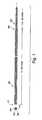
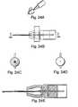
- FIG. 1shows a cross-sectional side and end view illustrating the structure of a guidewire probe with a linear whip antenna according to the invention.
- FIG. 2shows a cross-sectional side view illustrating the structure of one potential shielded linear whip antenna according to the invention.
- FIG. 3shows three potential alternate shapes for a linear whip antenna.
- FIG. 4shows a potential embodiment of the invention wherein the shielding comprises a series of balun circuits.
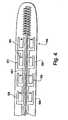
- FIG. 5shows a cross-sectional side and end view illustrating a guidewire probe according to an embodiment of the invention wherein the antenna whip comprises a combination whip where a helical coil is connected to a linear whip antenna at multiple points.
- FIG. 6shows a potential guidewire probe with a helical coil electronically connected to a linear whip antenna at a single point.
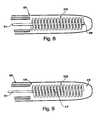
- FIG. 7shows a potential guidewire probe where a helical coil alone comprises a helical whip antenna.
- FIG. 8shows a potential guidewire probe where a helical coil is placed over a linear whip antenna without making an electrical connection between the two.
- FIG. 9shows a potential guidewire probe where a core is present inside a helical whip antenna.
- FIG. 10shows a representation of the receiving properties of a helical coil antenna.
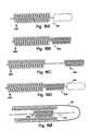
- FIG. 11shows a potential embodiment of a helical whip antenna where the diameter of the coils decreases from the proximate to the distal end of the helical whip antenna.
- FIG. 12shows a potential embodiment of a helical whip antenna where the diameter of the coils increases from the proximate to the distal end of the helical whip antenna.
- FIG. 13shows a potential embodiment of a helical whip antenna where the diameter of the coils varies along the length of the helical coil antenna.
- FIG. 14shows one potential guidewire probe of the instant invention where the probe shaft decreases in diameter at its distal end.
- FIG. 15shows an embodiment of the invention where a second helical coil is placed around the probe shaft and connected to the shielding.
- FIG. 16show embodiments of the invention where a second helical coils is used as shielding around various whip antennas of the invention.
- FIG. 17shows a potential snap-on connector of the instant invention.
- 17 Ashows the male connector portion and 1 7 B shows the female connector portion.
- FIG. 18shows a clip connector of the instant invention. 18 A is in unlocked form and 18 B is in locked form.
- FIG. 19shows a screw-lock connector of the instant invention.
- FIG. 20shows a screw style connector of the instant invention.
- 20 Ashows the female portion and 20 B shows the male portion.
- FIGS. 21-23show alternate connectors whereby there is no direct electric contact between the male and female members of the connector.
- FIGS. 24 and 25show different views of a connector of the instant invention which use a vice-like connector between the connector portion and the mated connector portion and allow the guidewire to rotate within the connector.
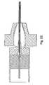
- FIG. 26shows a potential design of an interface box of the instant invention.
- FIG. 27shows a layout of a system of the instant invention wherein the guidewire probe might be used.
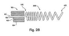
- FIG. 28shows a potential embodiment of a helical whip antenna where the spacing between the coils varies along the length of the helical coil antenna.
- the inventioncan comprise any type of probe with any type of MRI antenna whether a whip antenna or not and whether of looped, loopless or of other design which is suitable for use as a guidewire as is understood in the art.
- the inventioncan also comprise any type of probe or other device for insertion into a subject, whether or not for use as a guidewire, that comprises a helical coil being used as an antenna.
- any type of biopsy deviceany type of interventional tool; any type of probe or device which could be used simultaneously to an interventional tool; any type of catheter, known now or later discovered, including, but not limited to, catheters for any use associated with endovascular, urinary, nasogastric, endotrachial, endobilliary, peritoneal, intracranial, intradural, intraarticular, urologic, nasopharyngeal (including endonasal approaches to the cella turcica) procedures; any type of probe, known now or later discovered, including, but not limited to, probes for any use associated with endovascular, urinary, nasogastric, endotrachial, endobilliary, peritoneal, intracranial, intradural, intraarticular, urologic, nasopharyngeal (including endonasal approaches to the cella turcica) procedures; any type of tube including, but not limited to, a jejeunosto
- the subject of the inventionis also not limited to human beings but can be used on any subject where the use of a guidewire is desired.
- applications of the probe in the body or portion of the body of any human, non-human animal, or other biological organism, living, deceased or otherwiseinclude but are not limited to, applications of the probe in the body or portion of the body of any human, non-human animal, or other biological organism, living, deceased or otherwise; applications involving placement of the probe in any fluid, gel, solid, gas, plasma or other state of matter where the use of a guidewire is desired in that matter, placing the probe in the vicinity of a portion of a subject for the purpose of viewing that portion of that subject through the probe's proximity, or guiding a device to within that portion's proximity; the use of a probe to simultaneously guide an interventional device and image the area on which the interventional device is to be used; or any of the previous in any combination.
- the inventionis also not limited to a conventional MRI machine used medically but can be used in any type of scanning device that can measure magnetic resonance. Therefore, we use the term MRI machine to apply to any type of machine, device, system, means, or process which allows the detection of magnetic resonance in any type or state of matter, such device being currently known or later developed, whether for use on humans, non-human animals, other biological organisms, biological tissues or samples, or inorganic matter.
- Such an MRI machinemay be of any shape and for scanning any size subject or portion of a subject.
- guidewiresare also not limited to vascular interventions. Guidewires are commonly used in many non-vascular applications for the placement of various probes and catheters into the gastrointestinal (GI) tract, the biliary duct, the urethra, bladder, ureter and other orifices, punctures, or surgical openings. Systems according to the present invention may be adapted to a plurality of minimally invasive applications. Guidewires according to the present invention may, in certain embodiments, be used for passage into and through the upper airway, trachea and bronchial tree. Examination of these structures using the systems of the present invention may be performed to detect abnormalities of the lungs or tracheobronchial tree, ideally at an early stage for early treatment.
- the early detection of a pre-malignant lesion in the tracheobronchial treecould permit early extirpation before an invasive cancer develops; even if an invasive cancer is detected, it may be possible to detect and treat these lesions at their earliest stages, before lymph node invasion or distant metastasis.
- the systems and methods of the present inventionare applicable to any body lumen or body cavity wherein early detection of pre-malignant and malignant disease is desirable.
- these systems and methodscould be used for the evaluation of the esophagus, stomach and biliary tree to identify neoplasms and to distinguish benign from malignant tissue proliferation.
- these systems and methodscould be used for the evaluation of the colon and rectum to identify abnormalities and malignancies.
- These systems and methodscould also be used for the evaluation of the male and female urogenital systems, including bladder, urethra, prostate, uterus, cervix and ovary, to identify therein abnormalities and malignancies.
- the diagnostic function of the MRIwould be useful in the evaluation of any mucosal malignancy to identify how far through the wall of the affected organ the malignancy has invaded. It is understood in the art that extent of invasiveness into and through the wall, diagnosable by MRI, is an important characteristic of an intraluminal cancer.
- the diagnostic function of the MRI, as the probe is guided to the target tissue,may be combined with therapeutic interventions.
- a small lesion found within a body lumen using the systems and methods of the present inventionmay be suitable for localized ablation, wherein the lesion's response to the delivery of radio frequency energy or other ablative energy can be monitored in near real time by the high resolution MRI as disclosed herein.
- the scale of the devices described hereinmay be dimensionally adaptable to a number of body cavities and lumens traditionally inaccessible to interventive methods known in the prior art.
- the eustachian tube, the nasal airways and the craniofacial sinusesmay all be accessible to a probe designed in accordance with the present disclosure.
- Using one of these orifices as an entryway into the craniofacial skeletonmay permit the diagnosis or evaluation of a variety of otolaryngological and neurological conditions with greater precision than is currently available using whole-patient CT or MRI.
- transsphenoid evaluation of intracranial or sellar lesionsmay be possible.
- the imaging of these lesionsmay be combined with therapeutic techniques for extirpating or otherwise treating the lesion using minimally invasive technologies.
- an aneurysm of the Circle of Willisthat is identified using high-resolution MRI may be suitable for clipping under MRI guidance using minimally invasive techniques.
- a pituitary tumorcan be evaluated for its extensiveness using these systems and methods, and its resection can be precisely monitored.
- Use of these systems and methodsmay also permit diagnosis of abnormalities in organs considered inaccessible to traditional monitoring methods.
- the pancreasmay be examined, using an embodiment of the present invention, permitting the early diagnosis of pancreatic lesions.
- embodiments of the present inventionmay be adapted for intracranial use, for the diagnosis of lesions of the central nervous system or for precise anatomic delineation thereof.
- Ablative techniquesmay be combined with these diagnostic modalities to permit treatment of abnormalities using embodiments of the present invention to help determine the extent of the pathology and to monitor the effectiveness of the ablation in removing the abnormality.
- Trigeminal neuralgiais an example of a condition where delineation of the relevant intracranial anatomy is vital for the identification of the neuroanatomical structures to be ablated or treated.
- MRIusing the systems and methods of the present invention may usefully help direct the surgeon to the precise tissues requiring treatment.
- MRI guidancemay be particularly valuable in determining the extensiveness of a lesion that is to be resected or biopsied.
- mediastinoscopyit may be difficult to distinguish between large blood-filled vessels and pathological lymph nodes, the latter being the target for the biopsy being performed. The operator performing the procedure must sample the pathological lymph nodes without damaging the large vessels in the area, an inadvertancy that can result in profound, even exsanguinating hemorrhage.
- MRI guidance according to these systems and methodscan not only distinguish among the various types of anatomic structures, but also can map out the extent of lymph node involvement and direct the operator towards those lymph nodes most likely to bear the abnormal tissue being sought.
- a number of applicationswill be readily apparent to practitioners of ordinary skill in the art, whereby a conventional endoscopy procedure combined with these systems and methods will permit the diagnostic evaluation of a tissue or organ within a body lumen or a body cavity.
- the intraperitoneal spacemay be usefully evaluated using these systems and methods, with access to this space being provided by laparoscopic instrumentation, and with MRI being used to approach and identify target tissues.
- Intraperitoneal diagnosis using these systems and methodsmay be helpful in diagnosis of various retroperitoneal lymphadenopathies, such as those indicative of lymphoma, or such as those indicative of spread from a malignant melanoma of the lower extremity.
- various retroperitoneal lymphadenopathiessuch as those indicative of lymphoma, or such as those indicative of spread from a malignant melanoma of the lower extremity.
- Other examplesmay be evident to ordinarily skilled practitioners in the medical arts.
- contrast agentsin addition to the systems and methods described herein may permit identification of tumors on the basis of their abnormal blood flow or metabolism. Contrast agents or other markers carried by body fluids may permit these systems and methods to be used for diagnosis of abnormal bleeding sites, such as occult gastrointestinal bleeding points or bleeding varices, situations where direct visual inspection of the lesion may have limited diagnostic or therapeutic value.
- the present inventionmay be adapted for screening procedures using probes dimensionally adapted for appropriate bodily orifices.
- these systems and methodsmay be useful in identifying and determining extensiveness of gynecological cancers, including cervical cancer, uterine cancer and ovarian cancer.
- Other applicationsshould become available to practitioners of ordinary skill in the art with no more than routine experimentation.
- the probe of this inventioncan be described and understood as having multiple different forms of antenna whip and design. The first of which is depicted in FIG. 1 wherein the probe comprises a linear whip antenna 106 .
- the whiprefers to the antenna at the end of the probe which is a whip antenna.
- the whipcomprises a primarily unbent protrusion and is therefore called a linear whip antenna 106 .
- the probepreferably comprises a probe shaft 105 with a distal end 109 and a proximate end 111 .
- the probe shaftcan be comprised of multiple layers of different materials including a core 101 having at least one first electrically conducting component, a first insulator/dielectric 102 for providing insulation, a shielding 103 having at least one second conducting component, and an optional second insulator/dielectric 104 as shown in FIG. 2 .
- the linear whip antenna 106extends from the distal end 109 of the probe shaft 105 .
- a linear whip antenna 106does not have to be straight but may have a curve or slight hook at the end as is understood in the art to facilitate engagement of the device into complex vessels or other openings (such as ducts etc.) as shown in FIG. 3 .
- the linear whip antenna 106would be straight or straight and flexible or could be bent to form other non-linear shapes as the probe was twisted through complicated pathways within the subject.
- the linear whip antennacan comprise a ribbon or paddle shape such as those shown in FIG. 16 .
- the core 101can comprise a super-elastic material such as the Tinol® range of materials (also known as Nitinol or NiTi).
- Super-elasticsgenerally comprise a titanium-nickel alloy and have many positive attributes for use as a base for the probes of this invention. Super-elastics may be significantly deformed and still return to their original shape. Such deformation and“shape memory” can take place through actions based on changes in temperature.
- Super-elastic materialsare also known for high biocompatibility and show good properties for use within biological organisms or matter.
- Super-elastics in the antenna designs of this inventioncould be of any shape including wire, ribbon, microtubing, sheets or any other form as is known to the art but in one embodiment will comprise Nitinol wire that can be plated with layers of gold-silver-gold, or layers of gold, silver, copper, or aluminum applied either singly or in combination.
- the core 101can alternatively comprise different materials, including, but not limited to, MR-compatible stainless steel, other metallic materials that are non-magnetic, non-metallic substances such as carbon, glass fiber, or polymer, that can be plated with a layer of a good RF conductor such as copper, silver, gold, or aluminum either singly or in multiple layers, or any of the previous in any combination.
- the surfacecan be readily oxidized as is known to the art to provide the first insulator/dielectric 102 .
- the first insulator/dielectric 102 and the second insulator/dielectric 104may comprise any insulator/dielectric as is known to the art including any polymer, such as, but not limited to, an elastomeric grade PEBAX, Nylon, Teflon®, polyurethane, fluoroethylene polymer (FEP), or polyvinylidene fluoride (PVDF), or any combination of polymers with appropriate electrical properties.
- the insulator/dielectriccould also comprise aluminum oxide or any other nonpolymeric element or compound as would be understood by one of skill in the art.
- the thickness of the first insulator/dielectric 102 and the second optional insulator/dielectric 104can be determined so as to control the impedance of the cable formed.
- the wirecan have a uniform impedance throughout the length or the impedance can vary with length, for instance, by having low impedance closer to the proximate end 111 as compared to the distal end 109 .
- the shielding layer 103may comprise any MR-compatible conductive material including, but not limited to, copper plated with silver, copper plated with gold, Nitinol plated with gold, conductive inks, conductive coatings or any of the previous in any combination.
- the shieldingcan be in the form of a braid, a mesh, or a continuous tubing such as, but not limited to, a gold-silver-gold plated Nitinol hypotube.
- the shieldingcan be continuous or coiled toward the distal end 109 and can extend beyond the distal end 109 of the probe shaft 105 or may be discontinued at the distal end 109 of the probe shaft 105 . Discontinuing the shielding can create a stronger signal from the antenna, but may create detrimental effects when the probe is used in a human body.
- the shielding 103can be added to the probe shaft in the form of a balun circuit as is understood in the art. This reduces the effect of induced currents due to external RF and magnetic fields.
- the tertiary shielding 451can be continuous or discontinuous. It can have capacitors connecting the discontinuous sections or it can be connected directly to the primary shielding 461 or connected to the primary shielding 461 with capacitors 471 or by any other method understood in the art, or by a series of balun circuits 139 as shown in FIG. 4 .
- a balun circuitis placed on the probe in a tuned form (also known as a zenooka circuit) as is known to the art.
- This tuned balun circuitcould help to increase the SNR performance and reduce the induced currents on the wire during an RF pulse transmission by any external RF coil (such as the transverse magnetic field in an MRI machine).
- This circuitmay also decrease the risk of possible excessive Ohmic heating from the presence of the probe inside the body.
- the second optional insulator/dielectric 104is desirable over the antenna whip as depicted in FIG. 2 so as not to insert a straight cylindrical segment of bare wire into the patient with direct blood and tissue contact.
- the problem with this solutionis that the optimal length of the whip portion of the device is determined based upon the operating electromagnetic wavelength in vivo which in turn depend upon the effective dielectric constant as experienced by the antenna. For the case of a bare wire loaded in water, this length is approximately 4-12 cm, which represents a reasonable length for in vivo use.
- the addition of a second insulator/dielectric 104 to the outer surface of the antennahowever, decreases the effective dielectric constant, which in turn increases the operating wavelength and thus increases the optimal whip length from 4-12 cm.
- an alternative insulated whip designcould be desired when the antenna is insulated as is discussed below.
- covering the antenna with a second insulator/dielectric 104increases the diameter of the antenna making it increasingly difficult to insert in small vessels.
- the linear whip antenna 106has the narrowest possible diameter to allow such insertion.
- a typical assembly procedure for an MRI probe of the present inventioncan involve the following steps. First, the first insulator/dielectric 102 is attached to a gold-silver-gold plated Nitinol core 101 . This can be done by means of extrusion, drawing, a heat shrink tubing, or any other method known to the art. Next, the shielding 103 is loaded on the assembly leaving a portion of the assembly exposed to act as the linear whip antenna 106 . This can be done by means of braiding, plating, painting, sputtering, or any other means known to the art. Alternatively, a metallic hypotube can be used instead of braiding to add mechanical stiffness to the probe shaft.
- the second insulator/dielectric 104is loaded on the probe shaft 105 .
- a connectorcan then be attached to the proximate end 111 of the probe shaft 105 to facilitate connecting to the interface circuitry to be connected to the MRI scanner.
- the connectorcan be any type as is known to the art, or could alternatively be any of the connectors described below.
- the connectorcan be replaced by mechanical forming of the proximal tip to enable attachment of a snap-fit connector or by any other means of connections or termination of the probe as would be known to one of skill in the art.
- An optional coating of lubricantmay further be added to the probe shaft 105 and/or antenna whip to reduce drag.
- the linear whip antenna 106 and probe shaft 105could be manufactured as a single piece as is described above.
- the probe shaft 105 and linear whip antenna 106could be constructed as two separate pieces and attached together by any means known to the art either permanently (including, but not limited to, use of high temperature or cold impact welding, soldering and/or electrically conducting glue or epoxy) or removeably (including, but not limited to, a snap-on or locking connection).
- FIGS. 5, 6 , 7 , and 9show alternative embodiments of the invention using a helical coil antenna that obtains through its shape the ability to be the same physical length as a linear whip antenna, while still maintaining the electrical length of a much longer linear whip and therefore having desirable properties even when shielded by a second insulator/dielectric 104 .
- FIGS. 5 and 6show a combination whip antenna 206 where a helical coil is placed over and electrically joined to a linear whip antenna 101 .
- FIG. 7shows a guidewire probe with a helical coil whip antenna 306 where the helical coil 208 comprises the antenna alone.
- FIG. 9shows a variation on the helical coil whip antenna 306 of FIG.
- the core 217can provide modification to the flexibility of the helical coil whip antenna 306 for insertion into, or navigation inside, a subject.
- the core 217can be of non-conducting material including, but not limited to, a polymer, or can be an electrically conducting material.
- the core 217will usually be non-magnetic. replace the paragraph beginning at page 22 , line 13 , with the following paragraph:
- Helically coiling the antennashortens the physical antenna length while still producing optimum performance. Covering the antenna with an insulator, usually requires increasing the antenna length to obtain optimum performance because the insulator affects the ability of the antenna to detect signal. In this case, coiling the antenna can be used to compensate for this increase in antenna length. That is, a coil of wire can contain a longer piece of wire in a shorter physical form.
- a helical coil antennahas further mechanical advantages over a linear antenna.
- a coilis flexible and “springy” allowing it to navigate through complicated biological pathways without bending, kinking, or breaking, as opposed to a linear antenna which can have many of these problems since it is narrow and may have poor mechanical properties. Therefore, in one embodiment of this invention the helical coil is placed over a linear antenna, not necessarily to change signal, but to “superimpose” preferred mechanical properties on the linear antenna as exemplified in FIG. 8 .
- the helical coilalso provides for detection of magnetic resonance in multiple directions.
- the signal received by a linear antennais dependent upon the orientation of the antenna with respect to the main magnetic field as is known to the art.
- a linear antenna designbecomes bent or changes geometric planes, the sensitivity of the antenna and thus image quality can be degraded, with zero signal detected in some cases.
- an antenna designcapable of removing this orientation dependency would be desirable in many cases.
- the unique physical geometry of the helical coil antennaallows detection of radio frequencies from two orthogonal components of the processing transverse magnetization, which is known as quadrature detection.
- Quadrature designsare able to create a circularly polarized electric field that results in a 50% reduction in RF power deposition and up to a 40% increase in signal to noise ratio.
- such a designallows the imaging capabilities of the device to be independent of spatial orientation and therefore it can be used in any vessel or other area in the body.
- Helical coil antennashave two distinct and very different operating modes depending upon, as shown in FIG. 10, the physical dimensions of the windings and speed of wave propagation through the medium.
- the helical coil antennaoperates in an end fire or axial mode, where polarization occurs primarily along the axis of the helix as depicted in FIG. 10 ( b ). This is similar to the operation of the linear antenna.
- the helical antennaWhen D ⁇ and S ⁇ are much smaller than , the helical antenna is said to operate in normal mode where polarization occurs orthogonal or broadside to the helical axis as shown in FIG. 10 ( c ) and described in equation (1). Since the RF frequencies used in MRI tend to be very long, normal mode operation is the standard for a probe of the present invention.
- FIGS. 5 and 6show a probe with a helical coil 208 on top of a linear whip antenna 106 .
- the connection pointcould be at the distal end 215 of the linear whip antenna 106 instead of at the proximate end 223 as shown in FIG. 6 .
- a thin insulator 210may be placed between the linear whip antenna 106 and the helical coil 208 in any combination antenna 206 .
- FIG. 5 and 6shows a probe with a helical coil 208 on top of a linear whip antenna 106 .
- FIGS. 5 and 6show a probe with a helical coil 208 on top of a linear whip antenna 106 .
- FIGS. 5 and 6show a probe with a helical coil 208 on top of a linear whip antenna 106 .
- the helical coil 208 and the linear whip antenna 106are not electrically connected to each other.
- the helical coil 208provides beneficial mechanical properties to the linear whip antenna 106 .
- itcan make the linear-whip antenna 106 more rugged and more flexible allowing for better mechanical properties within the subject.
- the probe shaft 105can be built similarly to the probe shaft of FIG. 1 and all listed materials for the probe of FIG. 1 are also available for the probes of FIGS. 5, 6 , 7 , 8 , and 9 . This type of construction is not limited to these figures. Any probe shaft 105 in any embodiment herein described may be constructed in a similar manner.
- the helical coil 208will generally be added to a preconstructed probe with a linear whip antenna 106 .
- the additioncan either complete the electrical connection to the helical coil 208 or not depending on the desired final probe.
- the probecan be manufactured with the helical coil 208 already attached to the probe in any configuration.
- the helical coil 208comprises the entire helical coil whip antenna 306 .
- the helical coil 208is electrically connected to the core 101 of the probe shaft 105 .
- the whipis entirely helically coiled.
- This configurationcan provide advantages in mechanical properties.
- the helical coil whip antenna 306can be physically shorter or narrower than the combination whip antennas 206 depicted in FIGS. 5, 6 , and 8 without significant loss of electrical length.
- the helical coil whip antenna 306since the helical coil whip antenna 306 has no linear portions and is only coiled, it is more flexible than any of the other antennas allowing it to turn sharper corners in the subject.
- the helical coil whip antenna 306is more deformable than any of the previous antenna designs which makes the antenna less likely to puncture vessel walls. If desired, the flexibility of this antenna can be adjusted by including a core component 217 attached to the distal end 109 of the probe shaft 105 if nonconducting or unattached if conducting, as shown in FIG. 9 . Core 217 need not extend to the distal end 415 of the helical coil whip antenna 306 .
- FIGS. 11, 12 and 13depict alternative embodiments of the helical coil whip antenna 306 that can be used in place of the whip designs shown in FIGS. 7 and 9.
- the helical coil whip antenna 306has been tapered with decreasing diameter towards the distal end 415 to vary the flexibility of the whip such that it is more flexible at the tip to negotiate blood vessels and the like.
- the helical coil whip antenna 306is tapered on the proximal end 515 to stiffen the flexibility at the distal end 415 .
- the helical whip antenna 306is tapered at both ends. The taper can be adjusted to provide the desired flexibility gradient.
- the tapercan also repeat at regular intervals (either smoothly or at a sudden transition) or coils of different diameters can be placed anywhere within the length of the helical coil whip antenna 306 .
- the distal end 109 of the probe shaft 105can be tapered to improve the transition between the probe shaft 105 and any type of whip antenna (a helical coil whip antenna 306 is shown) as shown in FIG. 14 .
- the spacing between the coilscan also be modified. As shown in FIG. 28 the spacing of the coils can be closer together at the proximate end 515 and further apart at the distal end 415 . This arrangement may allow the construction of a helical coil whip antenna that has greater electrical length but preserves the desired mechanical properties present in a looser packed coil. Alternatively to FIG. 28, the coil spacing could be altered so that the spacing is tighter at the distal end 415 than the proximate end 515 , the coil spacing could follow any type of regular change from tighter to looser coils along its length, or the coil spacing could contain coils of random spacing.
- the optimum coil lengthmay be preferably calculated or measured as the length that minimizes the real component of the impedance of the antenna as the impedance of the antenna is measured at the point where the shield ends. This length is usually around 0.25 or less times the electromagnetic wavelength of the RF MRI signal in the medium, but other lengths could be used as would be understood by one of skill in the art.
- FIG. 15shows yet another embodiment of the present invention
- a second helical coil 408is connected to the shielding 103 at point 513 of the probe shaft 105 to concentrate the MRI signal sensitivity to a narrow range.
- the second helical coil 408can also be connected to multiple points for multiple different electrical properties as would be understood by one of skill in the art.
- the shield 103is completely or partially replaced by the second helical coil 408 which extends for the length of the shaft, insulated from the core 101 by dielectric 102 .
- These arrangementscan be used with any type of whip antenna including, but not limited to, those shown in FIG. 16 .
- a linear whip antenna 106as shown in FIG.
- the second insulator/dielectric 104is extended over the second helical coil 408 so as to provide protection to the subject from the antenna's interaction with exposed body fluids, tissues, or other portions of the subject as is depicted in FIG. 16 E.
- the second helical coil 408can also have any alterations of the coil's diameter or spacing along the second helical coil's 408 length as have been previously discussed with regards to the helical coil whip antenna 306 .
- connection between this electronic circuit and the probeis a further portion of the invention because a standard RF BNC connector as is known to the art is not well suited for frequent connection and disconnection. In many current procedures where an MRI guidewire would be desired, the tools used as part of those procedures must be changeable without having to remove the guidewire from the subject.
- a connectoris used to make an electrical connection between the probe and a tuning/matching and decoupling circuit or interface box of the present invention. This connector connects the interface to the antenna and can be removed and reinstalled as required during an interventional procedure to load and unload other interventional devices.
- FIGS. 17 through 25show some examples of connectors of the present invention which are discussed in detail below.
- FIG. 26shows one embodiment of an interface box for use between the MRI machine and the guidewire of the instant invention.
- One embodiment of the interface boxconsists of a shielded box 601 with two compartments 607 and 617 , separated by a partition 605 . In one embodiment, all components are non-magnetic.
- the probeattaches to coaxial connector 611 or another mating connector portion designed to attach to the connector portion of the probe.
- Coaxial connector 611can be insulated from the interface box 601 .
- the balancing of the dipole 611is accomplished by capacitor 613 and coil 615 .
- Coil 615 in one embodimentis a short length (5-10 cm) of 1 mm diameter solid-shield, 50 ohm coaxial cable, which is wound into a coil, increasing the inductance of both the center conductor as well as the shield.
- itcan be important to present a high impedance to current flow in the shielding 103 of the probe near the interface box 601 .
- This high impedanceis accomplished by tuning the LC circuit formed by capacitor 613 and the inductance of the shield of coil 615 .
- capacitor 613is selected such that the impedance of the network comprising capacitor 613 and coil 615 matches the impedance of the shielding 103 of the probe.
- the shield portion of the coaxial cable that forms coil 615can be electrically connected to the partition 605 of the interface box 601 as shown in FIG. 26 .
- the center conductor of the coaxial cable that forms the coil 615feeds through the partition 605 in the interface box 601 .
- the inductance of the center conductor of the coil 615 , and capacitor 613form a tuned circuit that can decouple the probe from the imaging pulses of the MRI machine connected at a coaxial connector 619 (these imaging pulses usually occur at 63.9 MHz).
- Capacitor 621can be tuned to maximize probe impedance when PIN diode 623 is turned on during imaging pulses. PIN diode 623 is turned on by a DC level being applied to coaxial connector 619 by the MRI scanner during MRI pulse transmission.
- the probecan be tuned to match the generally 10 to 80 Ohm impedance of the MRI scanner amplifier by the network of inductor 625 and capacitor 627 .
- This tuningcan be accomplished by connecting a network analyzer to coaxial connector 617 and varying the value of the capacitor 627 until the measured impedance is the desired impedance at based on the frequency of the imaging pulses (usually 63.9 MHz).
- the end of the guidewire antennacan contain a connector portion that allows radio frequency signals to propagate from the scanner to the guidewire antenna and vice versa by connecting the connector portion to a mated connector portion.
- This connectorcan be a standard BNC connector or one of the special miniaturized connectors shown in FIGS. 17 through 25.
- the connectorsallow for direct insertion of the guidewire into interventional devices such as balloon angioplasty catheter, stent placement devices.
- the connector diametershould be no larger than guidewire probe diameter. Standard connector sizes, however, are often larger than the probe diameter and therefore do not allow for rapid exchanging of interventional devices over the guidewire probe. To overcome this difficulty, we show eight different connector configurations. Although many other designs are possible, the most important feature of these designs are that the diameter of the connector portion on the guidewire probe is not significantly larger than the diameter of the guidewire probe.
- the connectors shown in FIGS. 17 through 20, 24 , and 25enable direct electrical contact between the conductors (shield and inner conductor of core) whereas the connectors shown in FIGS. 19-23 have no direct electrical contact.
- FIG. 17shows a snap-on connector.
- the connector at FIG. 17Ais the male connector portion. Its diameter is smaller or the same size as the diameter of the guidewire probe.
- FIG. 17Bis the female mated connector portion. They are connected to each other with a small amount of pressure in the direction along the length of the connector and removed easily by pulling the connectors apart.
- FIG. 18shows a clip connector.
- the male connector portion's 1002 diameteris not larger than the diameter of the guidewire probe.
- a clip lock mechanism, 1006the female mated connector portion 1003 is connected to the male connector portion 1002 .
- the mechanism shown by FIG. 18enables free rotation of the connector. This enables the user to freely rotate the guidewire while it is connected.
- 1004shows a coaxial cable connecting the interface box 1005 to the mated connector portion.
- FIGS. 24 and 25show an alternative design of this type of connector wherein a vice-like connection is employed instead of the clip. Again this design allows for the guidewire to rotate freely while it is connected.
- FIG. 19has the screw 1007 on the female mated connector portion that is an alternative to the clip lock mechanism, 1006 shown in FIG. 18 .
- FIG. 20shows another type of screw connector.
- FIG. 20Ais the female connector portion that is a part of the guidewire probe.
- the male mated connector portion shown in FIG. 20Bcan be connected to a coaxial cable that leads to the interface box.
- FIGS. 17 through 20One problem with the connectors shown in FIGS. 17 through 20 is difficulty in using in a wet environment. When the connectors are wet or have blood or other body fluids on them, their performance may degrade. Therefore, a connector was designed that can be used in wet environment. The connectors shown in FIGS. 21-23 do not require direct electrical contact between the two connector portions.
- FIG. 21shows a solenoidal coil 2005 inside both female and male connectors portions.
- the male connector portionsnaps in the female mated connector portion 2003 but the electrical wires are not touching each other.
- the signalis transmitted from one to the other by the coupling of electromagnetic waves.
- FIG. 22shows a coaxial cable with extended inner conductor 2105 as the mated connector portion 2103 and an opposed solenoidal coil 2107 as the connector portion 2101 on the guidewire probe.
- FIG. 23shows a loop coil 2305 in both ends of the connector.
- the male connector portion 2301snaps on the female mated connector portion 2303 .
- the electromagnetic wavesare transmitted from one coil to the other enabling connection.
- FIG. 27shows one potential layout of a system whereby a guidewire probe could be used.
- the subject 901is shown within the MRI machine 903 .
- the probe 3005has been inserted into the subject 901 .
- a display 905is showing an MRI 907 showing the probe 3005 and the surrounding biological tissue 909 .
- the probe 3005is connected to the interface box 1005 through a connector 1111 that will allow a doctor (not shown) or another individual or machine to load or unload tools without removing the probe 3005 from the subject 901 .
- the interface box 1005is connected to the MRI machine 903 allowing the MRI machine 903 to use the probe 3005 as an active antenna in the subject 901 .
Landscapes
- Physics & Mathematics (AREA)
- Health & Medical Sciences (AREA)
- Condensed Matter Physics & Semiconductors (AREA)
- General Physics & Mathematics (AREA)
- General Health & Medical Sciences (AREA)
- Pathology (AREA)
- Life Sciences & Earth Sciences (AREA)
- Pulmonology (AREA)
- Biophysics (AREA)
- Engineering & Computer Science (AREA)
- Anesthesiology (AREA)
- Biomedical Technology (AREA)
- Heart & Thoracic Surgery (AREA)
- Hematology (AREA)
- Animal Behavior & Ethology (AREA)
- Public Health (AREA)
- Veterinary Medicine (AREA)
- Magnetic Resonance Imaging Apparatus (AREA)
- Investigating Or Analyzing Materials By The Use Of Magnetic Means (AREA)
Abstract
Description
Claims (73)
Priority Applications (21)
| Application Number | Priority Date | Filing Date | Title |
|---|---|---|---|
| US09/536,090US6675033B1 (en) | 1999-04-15 | 2000-03-24 | Magnetic resonance imaging guidewire probe |
| DE60044456TDE60044456D1 (en) | 1999-04-15 | 2000-04-13 | PROBE WITH GUIDE WIRE FOR PICTURE GENERATION BY MAGNETIC RESONANCE |
| ES00922135TES2346633T3 (en) | 1999-04-15 | 2000-04-13 | WIRE PROBE GUIDE FOR THE GENERATION OF IMAGES BY MAGNETIC RESONANCE. |
| EP00922135AEP1169749B1 (en) | 1999-04-15 | 2000-04-13 | Magnetic resonance imaging guidewire probe |
| PCT/US2000/009875WO2000064003A2 (en) | 1999-04-15 | 2000-04-13 | Magnetic resonance imaging guidewire probe |
| AT00922135TATE469360T1 (en) | 1999-04-15 | 2000-04-13 | PROBE WITH GUIDE WIRE FOR IMAGING USING MAGNETIC RESONANCE |
| CA2372001ACA2372001C (en) | 1999-04-15 | 2000-04-13 | Magnetic resonance imaging guidewire probe |
| JP2000613033AJP4851010B2 (en) | 1999-04-15 | 2000-04-13 | Magnetic Resonance Imaging Guidewire Probe |
| AU42368/00AAU779202B2 (en) | 1999-04-15 | 2000-04-13 | Magnetic resonance imaging guidewire probe |
| US09/549,921US6549800B1 (en) | 1996-04-25 | 2000-04-14 | Methods for in vivo magnetic resonance imaging |
| AT01910403TATE484757T1 (en) | 2000-02-01 | 2001-02-01 | TRANSSEPTAL NEEDLE ANTENNA FOR AN MR IMAGING DEVICE |
| CA002398967ACA2398967A1 (en) | 2000-02-01 | 2001-02-01 | Magnetic resonance imaging transseptal needle antenna |
| US09/775,338US6606513B2 (en) | 2000-02-01 | 2001-02-01 | Magnetic resonance imaging transseptal needle antenna |
| EP01910403AEP1267713B1 (en) | 2000-02-01 | 2001-02-01 | Magnetic resonance imaging transseptal needle antenna |
| AU2001238012AAU2001238012A1 (en) | 2000-02-01 | 2001-02-01 | Magnetic resonance imaging transseptal needle antenna |
| DE60143258TDE60143258D1 (en) | 2000-02-01 | 2001-02-01 | TRANSSEPTAL NEEDLE ANTENNA FOR A MR IMAGING APPARATUS |
| PCT/US2001/003346WO2001056469A2 (en) | 2000-02-01 | 2001-02-01 | Magnetic resonance imaging transseptal needle antenna |
| US09/824,536US6898454B2 (en) | 1996-04-25 | 2001-04-02 | Systems and methods for evaluating the urethra and the periurethral tissues |
| US10/123,065US7848788B2 (en) | 1999-04-15 | 2002-04-11 | Magnetic resonance imaging probe |
| US10/640,406US7551953B2 (en) | 1999-04-15 | 2003-08-12 | Magnetic resonance imaging needle antennas |
| US11/136,329US7599729B2 (en) | 1996-04-25 | 2005-05-24 | Evaluating the urethra and the periurethral tissues |
Applications Claiming Priority (2)
| Application Number | Priority Date | Filing Date | Title |
|---|---|---|---|
| US12936499P | 1999-04-15 | 1999-04-15 | |
| US09/536,090US6675033B1 (en) | 1999-04-15 | 2000-03-24 | Magnetic resonance imaging guidewire probe |
Related Parent Applications (2)
| Application Number | Title | Priority Date | Filing Date |
|---|---|---|---|
| US36014499AContinuation-In-Part | 1996-04-25 | 1999-07-26 | |
| US09/549,921Continuation-In-PartUS6549800B1 (en) | 1996-04-25 | 2000-04-14 | Methods for in vivo magnetic resonance imaging |
Related Child Applications (6)
| Application Number | Title | Priority Date | Filing Date |
|---|---|---|---|
| US09/549,921Continuation-In-PartUS6549800B1 (en) | 1996-04-25 | 2000-04-14 | Methods for in vivo magnetic resonance imaging |
| US09/775,338Continuation-In-PartUS6606513B2 (en) | 1999-04-15 | 2001-02-01 | Magnetic resonance imaging transseptal needle antenna |
| US09/824,536Continuation-In-PartUS6898454B2 (en) | 1996-04-25 | 2001-04-02 | Systems and methods for evaluating the urethra and the periurethral tissues |
| US10/123,065Continuation-In-PartUS7848788B2 (en) | 1999-04-15 | 2002-04-11 | Magnetic resonance imaging probe |
| US10/640,406Continuation-In-PartUS7551953B2 (en) | 1999-04-15 | 2003-08-12 | Magnetic resonance imaging needle antennas |
| US11/136,329Continuation-In-PartUS7599729B2 (en) | 1996-04-25 | 2005-05-24 | Evaluating the urethra and the periurethral tissues |
Publications (1)
| Publication Number | Publication Date |
|---|---|
| US6675033B1true US6675033B1 (en) | 2004-01-06 |
Family
ID=26827501
Family Applications (1)
| Application Number | Title | Priority Date | Filing Date |
|---|---|---|---|
| US09/536,090Expired - LifetimeUS6675033B1 (en) | 1996-04-25 | 2000-03-24 | Magnetic resonance imaging guidewire probe |
Country Status (9)
| Country | Link |
|---|---|
| US (1) | US6675033B1 (en) |
| EP (1) | EP1169749B1 (en) |
| JP (1) | JP4851010B2 (en) |
| AT (1) | ATE469360T1 (en) |
| AU (1) | AU779202B2 (en) |
| CA (1) | CA2372001C (en) |
| DE (1) | DE60044456D1 (en) |
| ES (1) | ES2346633T3 (en) |
| WO (1) | WO2000064003A2 (en) |
Cited By (136)
| Publication number | Priority date | Publication date | Assignee | Title |
|---|---|---|---|---|
| US20030028095A1 (en)* | 1999-04-15 | 2003-02-06 | Steve Tulley | Magnetic resonance imaging probe |
| US20030050557A1 (en)* | 1998-11-04 | 2003-03-13 | Susil Robert C. | Systems and methods for magnetic-resonance-guided interventional procedures |
| US20030097064A1 (en)* | 2001-11-13 | 2003-05-22 | Dnyanesh Talpade | Impedance-matching apparatus and construction for intravascular device |
| US20030111142A1 (en)* | 2001-03-05 | 2003-06-19 | Horton Joseph A. | Bulk metallic glass medical instruments, implants, and methods of using same |
| US20040046557A1 (en)* | 2002-05-29 | 2004-03-11 | Parag Karmarkar | Magnetic resonance probes |
| US20040169514A1 (en)* | 2002-12-11 | 2004-09-02 | Friedrich Fuchs | Local coil for magnetic resonance applications |
| US20040181177A1 (en)* | 2000-11-20 | 2004-09-16 | Chris Lee | Guidewire and connector therefor |
| US20040199071A1 (en)* | 1999-04-15 | 2004-10-07 | Lardo Albert C. | Magnetic resonance imaging transseptal needle antenna |
| US20050038337A1 (en)* | 2003-08-11 | 2005-02-17 | Edwards Jerome R. | Methods, apparatuses, and systems useful in conducting image guided interventions |
| US20050070972A1 (en)* | 2003-09-26 | 2005-03-31 | Wahlstrand Carl D. | Energy shunt for producing an MRI-safe implantable medical device |
| US20050222642A1 (en)* | 2004-03-30 | 2005-10-06 | Medtronic, Inc. | Lead electrode for use in an MRI-safe implantable medical device |
| US20050222659A1 (en)* | 2004-03-30 | 2005-10-06 | Medtronic, Inc. | Lead electrode for use in an MRI-safe implantable medical device |
| US20050222647A1 (en)* | 2004-03-30 | 2005-10-06 | Wahlstrand Carl D | Lead electrode for use in an MRI-safe implantable medical device |
| US20050222656A1 (en)* | 2004-03-30 | 2005-10-06 | Wahlstrand Carl D | MRI-safe implantable medical device |
| US20050222658A1 (en)* | 2004-03-30 | 2005-10-06 | Medtronic, Inc. | Lead electrode for use in an MRI-safe implantable medical device |
| US20050251032A1 (en)* | 2004-05-06 | 2005-11-10 | Scimed Life Systems, Inc. | Intravascular antenna |
| US20050251031A1 (en)* | 2004-05-06 | 2005-11-10 | Scimed Life Systems, Inc. | Apparatus and construction for intravascular device |
| US20050253763A1 (en)* | 2004-05-11 | 2005-11-17 | Werner Douglas H | Novel frequency-agile beam scanning reconfigurable antenna |
| US20060100506A1 (en)* | 1998-11-04 | 2006-05-11 | Johns Hopkins University School Of Medicine | System and method for magnetic-resonance-guided electrophysiologic and ablation procedures |
| US20060200218A1 (en)* | 2005-02-01 | 2006-09-07 | Wahlstrand Carl D | Extensible implantable medical lead |
| US20060247747A1 (en)* | 2005-04-29 | 2006-11-02 | Medtronic, Inc. | Lead electrode for use in an MRI-safe implantable medical device |
| US20060247748A1 (en)* | 2005-04-29 | 2006-11-02 | Medtronic, Inc. | Lead electrode for use in an MRI-safe implantable medical device |
| US20060247684A1 (en)* | 2001-04-13 | 2006-11-02 | Greatbatch-Sierra, Inc. | Band stop filter employing a capacitor and an inductor tank circuit to enhance mri compatibility of active medical devices |
| US20070060799A1 (en)* | 2005-09-13 | 2007-03-15 | Lyon Torsten M | Apparatus and method for automatic image guided accuracy verification |
| US20070088416A1 (en)* | 2001-04-13 | 2007-04-19 | Surgi-Vision, Inc. | Mri compatible medical leads |
| US20070112398A1 (en)* | 2005-11-11 | 2007-05-17 | Greatbatch Ltd. | Tank filters placed in series with the lead wires or circuits of active medical devices to enhance mri compatibility |
| US20080049376A1 (en)* | 1998-11-04 | 2008-02-28 | Greatbatch Ltd. | Non-ferromagnetic tank filters in lead wires of active implantable medical devices to enhance mri compatibility |
| US20080058789A1 (en)* | 2006-09-06 | 2008-03-06 | Cardiofirst | Guidance system used in treating chronic occlusion |
| US20080065181A1 (en)* | 2001-04-13 | 2008-03-13 | Greatbatch, Ltd. | Rfid detection and identification system for implantable medical lead systems |
| US20080116997A1 (en)* | 2001-04-13 | 2008-05-22 | Greatbatch Ltd. | Cylindrical bandstop filters for medical lead systems |
| US20080132987A1 (en)* | 2001-04-13 | 2008-06-05 | Greatbatch Ltd. | Medical lead system utilizing electromagnetic bandstop filters |
| US20080195180A1 (en)* | 2006-06-08 | 2008-08-14 | Greatbatch Ltd. | Low loss band pass filter for rf distance telemetry pin antennas of active implantable medical devices |
| US20080195186A1 (en)* | 2007-02-14 | 2008-08-14 | Bernard Li | Continuous conductive materials for electromagnetic shielding |
| US20080195187A1 (en)* | 2007-02-14 | 2008-08-14 | Bernard Li | Discontinuous conductive filler polymer-matrix composites for electromagnetic shielding |
| US20080269863A1 (en)* | 2007-04-25 | 2008-10-30 | Medtronic, Inc. | Lead or lead extension having a conductive body and conductive body contact |
| US20080306375A1 (en)* | 2007-06-07 | 2008-12-11 | Surgi-Vision, Inc. | Mri-guided medical interventional systems and methods |
| US20090112084A1 (en)* | 2007-06-07 | 2009-04-30 | Surgi-Vision, Inc. | Mri-guided medical interventional systems and methods |
| US20090118610A1 (en)* | 2005-11-29 | 2009-05-07 | Karmarkar Parag V | Mri-guided localization and/or lead placement systems, related methods, devices and computer program products |
| US20090131783A1 (en)* | 2007-11-21 | 2009-05-21 | Surgi-Vision, Inc. | Methods, systems and computer program products for positioning a guidance apparatus relative to a patient |
| US20090177077A1 (en)* | 2007-09-24 | 2009-07-09 | Surgi-Vision, Inc. | Mri-compatible patches and methods for using the same |
| US20090192412A1 (en)* | 2008-01-23 | 2009-07-30 | Mediguide Ltd. | Sensor mounted flexible guidewire |
| US20090216109A1 (en)* | 2005-10-06 | 2009-08-27 | Karmarkar Parag V | MRI Compatible Vascular Occlusive Devices and Related Methods of Treatment and Methods of Monitoring Implanted Devices |
| US20090281566A1 (en)* | 2003-08-11 | 2009-11-12 | Edwards Jerome R | Bodily sealants and methods and apparatus for image-guided delivery of same |
| US20100063383A1 (en)* | 2008-09-11 | 2010-03-11 | Sunnybrook Health Sciences Centre | Catheter for magnetic resonance guided procedures |
| US20100069880A1 (en)* | 2008-09-18 | 2010-03-18 | Jeffrey Grayzel | Medical guide element with diameter transition |
| US7702387B2 (en) | 2006-06-08 | 2010-04-20 | Greatbatch Ltd. | Tank filters adaptable for placement with a guide wire, in series with the lead wires or circuits of active medical devices to enhance MRI compatibility |
| US20100100164A1 (en)* | 2006-11-09 | 2010-04-22 | Greatbatch Ltd. | Capacitor and inductor elements physically disposed in series whose lumped parameters are electrically connected in parallel to form a bandstop filter |
| US20100160997A1 (en)* | 2001-04-13 | 2010-06-24 | Greatbatch Ltd. | Tuned energy balanced system for minimizing heating and/or to provide emi protection of implanted leads in a high power electromagnetic field environment |
| US20100168821A1 (en)* | 2001-04-13 | 2010-07-01 | Greatbatch Ltd. | Switched diverter circuits for minimizing heating of an implanted lead in a high power electromagnetic field environment |
| US20100185198A1 (en)* | 2007-09-24 | 2010-07-22 | Peter Piferi | Head Fixation Assemblies for Medical Procedures |
| US20100191236A1 (en)* | 2001-04-13 | 2010-07-29 | Greatbatch Ltd. | Switched diverter circuits for minimizing heating of an implanted lead and/or providing emi protection in a high power electromagnetic field environment |
| US20100208397A1 (en)* | 2008-12-17 | 2010-08-19 | Greatbatch Ltd. | Switched safety protection circuit for an aimd system during exposure to high power electromagnetic fields |
| US20100217262A1 (en)* | 2001-04-13 | 2010-08-26 | Greatbatch Ltd. | Frequency selective passive component networks for active implantable medical devices utilizing an energy dissipating surface |
| US20100284580A1 (en)* | 2009-05-07 | 2010-11-11 | Ouyang Xiaolong | Tissue visualization systems and methods for using the same |
| US20100286477A1 (en)* | 2009-05-08 | 2010-11-11 | Ouyang Xiaolong | Internal tissue visualization system comprising a rf-shielded visualization sensor module |
| US7844344B2 (en) | 2004-03-30 | 2010-11-30 | Medtronic, Inc. | MRI-safe implantable lead |
| US20100312096A1 (en)* | 2009-06-08 | 2010-12-09 | Michael Guttman | Mri-guided interventional systems that can track and generate dynamic visualizations of flexible intrabody devices in near real time |
| US20100317962A1 (en)* | 2009-06-16 | 2010-12-16 | Jenkins Kimble L | MRI-Guided Devices and MRI-Guided Interventional Systems that can Track and Generate Dynamic Visualizations of the Devices in near Real Time |
| US20110009694A1 (en)* | 2009-07-10 | 2011-01-13 | Schultz Eric E | Hand-held minimally dimensioned diagnostic device having integrated distal end visualization |
| US20110152721A1 (en)* | 2008-01-23 | 2011-06-23 | Ran Sela | Sensor mounted flexible guidewire |
| US20110213233A1 (en)* | 2006-06-08 | 2011-09-01 | Greatbatch Ltd. | Tank filters placed in series with the lead wires or circuits of active medical devices to enhance mri compatibility |
| CN102271579A (en)* | 2008-12-31 | 2011-12-07 | 皇家飞利浦电子股份有限公司 | General inductive handpiece for active devices |
| US8095224B2 (en) | 2009-03-19 | 2012-01-10 | Greatbatch Ltd. | EMI shielded conduit assembly for an active implantable medical device |
| CN102393450A (en)* | 2011-08-03 | 2012-03-28 | 安徽大学 | Magnetic tweezers probe based on optical fiber |
| US8224462B2 (en) | 2005-11-11 | 2012-07-17 | Greatbatch Ltd. | Medical lead system utilizing electromagnetic bandstop filters |
| US8315689B2 (en) | 2007-09-24 | 2012-11-20 | MRI Interventions, Inc. | MRI surgical systems for real-time visualizations using MRI image data and predefined data of surgical tools |
| US8364279B2 (en) | 2008-09-25 | 2013-01-29 | Boston Scientific Neuromodulation Corporation | Electrical stimulation leads having RF compatibility and methods of use and manufacture |
| US8600519B2 (en) | 2001-04-13 | 2013-12-03 | Greatbatch Ltd. | Transient voltage/current protection system for electronic circuits associated with implanted leads |
| US8696549B2 (en) | 2010-08-20 | 2014-04-15 | Veran Medical Technologies, Inc. | Apparatus and method for four dimensional soft tissue navigation in endoscopic applications |
| US8712544B2 (en) | 2001-04-13 | 2014-04-29 | Greatbatch Ltd. | Electromagnetic shield for a passive electronic component in an active medical device implantable lead |
| US8781186B2 (en) | 2010-05-04 | 2014-07-15 | Pathfinder Therapeutics, Inc. | System and method for abdominal surface matching using pseudo-features |
| US8874228B2 (en) | 2004-07-27 | 2014-10-28 | The Cleveland Clinic Foundation | Integrated system and method for MRI-safe implantable devices |
| US8882763B2 (en) | 2010-01-12 | 2014-11-11 | Greatbatch Ltd. | Patient attached bonding strap for energy dissipation from a probe or a catheter during magnetic resonance imaging |
| US8903505B2 (en) | 2006-06-08 | 2014-12-02 | Greatbatch Ltd. | Implantable lead bandstop filter employing an inductive coil with parasitic capacitance to enhance MRI compatibility of active medical devices |
| US8977355B2 (en) | 2001-04-13 | 2015-03-10 | Greatbatch Ltd. | EMI filter employing a capacitor and an inductor tank circuit having optimum component values |
| US8979871B2 (en) | 2009-08-13 | 2015-03-17 | Monteris Medical Corporation | Image-guided therapy of a tissue |
| US9031670B2 (en) | 2006-11-09 | 2015-05-12 | Greatbatch Ltd. | Electromagnetic shield for a passive electronic component in an active medical device implantable lead |
| US9108066B2 (en) | 2008-03-20 | 2015-08-18 | Greatbatch Ltd. | Low impedance oxide resistant grounded capacitor for an AIMD |
| US9138165B2 (en) | 2012-02-22 | 2015-09-22 | Veran Medical Technologies, Inc. | Systems, methods and devices for forming respiratory-gated point cloud for four dimensional soft tissue navigation |
| US9179843B2 (en) | 2011-04-21 | 2015-11-10 | Hassan Ghaderi MOGHADDAM | Method and system for optically evaluating proximity to the inferior alveolar nerve in situ |
| US9186499B2 (en) | 2009-04-30 | 2015-11-17 | Medtronic, Inc. | Grounding of a shield within an implantable medical lead |
| US9192446B2 (en) | 2012-09-05 | 2015-11-24 | MRI Interventions, Inc. | Trajectory guide frame for MRI-guided surgeries |
| CN105212902A (en)* | 2014-10-22 | 2016-01-06 | 苏州亘科医疗科技有限公司 | Sensor Yarn guide component |
| US9248283B2 (en) | 2001-04-13 | 2016-02-02 | Greatbatch Ltd. | Band stop filter comprising an inductive component disposed in a lead wire in series with an electrode |
| US9295828B2 (en) | 2001-04-13 | 2016-03-29 | Greatbatch Ltd. | Self-resonant inductor wound portion of an implantable lead for enhanced MRI compatibility of active implantable medical devices |
| US9333038B2 (en) | 2000-06-15 | 2016-05-10 | Monteris Medical Corporation | Hyperthermia treatment and probe therefore |
| US9370295B2 (en) | 2014-01-13 | 2016-06-21 | Trice Medical, Inc. | Fully integrated, disposable tissue visualization device |
| US9427596B2 (en) | 2013-01-16 | 2016-08-30 | Greatbatch Ltd. | Low impedance oxide resistant grounded capacitor for an AIMD |
| US9433383B2 (en) | 2014-03-18 | 2016-09-06 | Monteris Medical Corporation | Image-guided therapy of a tissue |
| US9463317B2 (en) | 2012-04-19 | 2016-10-11 | Medtronic, Inc. | Paired medical lead bodies with braided conductive shields having different physical parameter values |
| US9468750B2 (en) | 2006-11-09 | 2016-10-18 | Greatbatch Ltd. | Multilayer planar spiral inductor filter for medical therapeutic or diagnostic applications |
| US9504484B2 (en) | 2014-03-18 | 2016-11-29 | Monteris Medical Corporation | Image-guided therapy of a tissue |
| US9731119B2 (en) | 2008-03-12 | 2017-08-15 | Medtronic, Inc. | System and method for implantable medical device lead shielding |
| WO2017142698A1 (en) | 2016-02-17 | 2017-08-24 | MRI Interventions, Inc. | Intrabody surgical fluid transfer assemblies with adjustable exposed cannula to needle tip length, related systems and methods |
| US9782582B2 (en) | 2015-03-27 | 2017-10-10 | Boston Scientific Neuromodulation Corporation | Systems and methods for making and using electrical stimulation systems to reduce RF-induced tissue heating |
| US9782581B2 (en) | 2014-06-27 | 2017-10-10 | Boston Scientific Neuromodulation Corporation | Methods and systems for electrical stimulation including a shielded sheath |
| USRE46699E1 (en) | 2013-01-16 | 2018-02-06 | Greatbatch Ltd. | Low impedance oxide resistant grounded capacitor for an AIMD |
| US9891296B2 (en) | 2013-09-13 | 2018-02-13 | MRI Interventions, Inc. | Intrabody fluid transfer devices, systems and methods |
| US9927504B2 (en) | 2012-09-12 | 2018-03-27 | Toshiba Medical Systems Corporation | Magnetic resonance imaging apparatus |
| US9931514B2 (en) | 2013-06-30 | 2018-04-03 | Greatbatch Ltd. | Low impedance oxide resistant grounded capacitor for an AIMD |
| US9993638B2 (en) | 2013-12-14 | 2018-06-12 | Medtronic, Inc. | Devices, systems and methods to reduce coupling of a shield and a conductor within an implantable medical lead |
| US10045686B2 (en) | 2008-11-12 | 2018-08-14 | Trice Medical, Inc. | Tissue visualization and modification device |
| US10080889B2 (en) | 2009-03-19 | 2018-09-25 | Greatbatch Ltd. | Low inductance and low resistance hermetically sealed filtered feedthrough for an AIMD |
| US10105485B2 (en) | 2010-04-16 | 2018-10-23 | MRI Interventions, Inc. | MRI surgical systems including MRI-compatible surgical cannulae for transferring a substance to and/or from a patient |
| US10155111B2 (en) | 2014-07-24 | 2018-12-18 | Medtronic, Inc. | Methods of shielding implantable medical leads and implantable medical lead extensions |
| US10173055B2 (en) | 2015-04-30 | 2019-01-08 | Boston Scientific Neuromodulation Corporaation | Electrical stimulation leads and systems having a RF shield along at least the lead and methods of making and using |
| US20190053760A1 (en)* | 2017-03-15 | 2019-02-21 | II Rex Ervin Gerald | Magnetic resonance imaging cancer probe and methods of use |
| WO2019043023A1 (en)* | 2017-08-31 | 2019-03-07 | Koninklijke Philips N.V. | Sensing guidewire with integrated proximal locking feature |
| US20190074082A1 (en)* | 2017-08-11 | 2019-03-07 | Elucid Bioimaging Inc. | Quantitative medical imaging reporting |
| US10279171B2 (en) | 2014-07-23 | 2019-05-07 | Medtronic, Inc. | Methods of shielding implantable medical leads and implantable medical lead extensions |
| US10327830B2 (en) | 2015-04-01 | 2019-06-25 | Monteris Medical Corporation | Cryotherapy, thermal therapy, temperature modulation therapy, and probe apparatus therefor |
| US10342579B2 (en) | 2014-01-13 | 2019-07-09 | Trice Medical, Inc. | Fully integrated, disposable tissue visualization device |
| US10350421B2 (en) | 2013-06-30 | 2019-07-16 | Greatbatch Ltd. | Metallurgically bonded gold pocket pad for grounding an EMI filter to a hermetic terminal for an active implantable medical device |
| US10405886B2 (en) | 2015-08-11 | 2019-09-10 | Trice Medical, Inc. | Fully integrated, disposable tissue visualization device |
| US10559409B2 (en) | 2017-01-06 | 2020-02-11 | Greatbatch Ltd. | Process for manufacturing a leadless feedthrough for an active implantable medical device |
| US10561837B2 (en) | 2011-03-01 | 2020-02-18 | Greatbatch Ltd. | Low equivalent series resistance RF filter for an active implantable medical device utilizing a ceramic reinforced metal composite filled via |
| US10589107B2 (en) | 2016-11-08 | 2020-03-17 | Greatbatch Ltd. | Circuit board mounted filtered feedthrough assembly having a composite conductive lead for an AIMD |
| US10617324B2 (en) | 2014-04-23 | 2020-04-14 | Veran Medical Technologies, Inc | Apparatuses and methods for endobronchial navigation to and confirmation of the location of a target tissue and percutaneous interception of the target tissue |
| US10624701B2 (en) | 2014-04-23 | 2020-04-21 | Veran Medical Technologies, Inc. | Apparatuses and methods for registering a real-time image feed from an imaging device to a steerable catheter |
| US10675113B2 (en) | 2014-03-18 | 2020-06-09 | Monteris Medical Corporation | Automated therapy of a three-dimensional tissue region |
| US10905497B2 (en) | 2017-04-21 | 2021-02-02 | Clearpoint Neuro, Inc. | Surgical navigation systems |
| US10905888B2 (en) | 2018-03-22 | 2021-02-02 | Greatbatch Ltd. | Electrical connection for an AIMD EMI filter utilizing an anisotropic conductive layer |
| US10912945B2 (en) | 2018-03-22 | 2021-02-09 | Greatbatch Ltd. | Hermetic terminal for an active implantable medical device having a feedthrough capacitor partially overhanging a ferrule for high effective capacitance area |
| WO2021071561A1 (en) | 2019-10-08 | 2021-04-15 | Clearpoint Neuro, Inc. | Extension tube assembly and related medical fluid transfer systems and methods |
| US11022664B2 (en) | 2018-05-09 | 2021-06-01 | Clearpoint Neuro, Inc. | MRI compatible intrabody fluid transfer systems and related devices and methods |
| US20210161460A1 (en)* | 2015-12-22 | 2021-06-03 | The University Of Sheffield | Apparatus and methods for determining electrical conductivity of tissue |
| WO2021126336A1 (en) | 2019-12-19 | 2021-06-24 | Clearpoint Neuro, Inc. | Front-loadable fluid transfer assemblies and related medical fluid transfer systems |
| EP3892214A1 (en) | 2020-04-08 | 2021-10-13 | ClearPoint Neuro, Inc. | Mri surgical systems including mri-compatible surgical cannulas for transferring a substance to and/or from a patient |
| US11198014B2 (en) | 2011-03-01 | 2021-12-14 | Greatbatch Ltd. | Hermetically sealed filtered feedthrough assembly having a capacitor with an oxide resistant electrical connection to an active implantable medical device housing |
| US11202888B2 (en) | 2017-12-03 | 2021-12-21 | Cook Medical Technologies Llc | MRI compatible interventional wireguide |
| US11253237B2 (en) | 2018-05-09 | 2022-02-22 | Clearpoint Neuro, Inc. | MRI compatible intrabody fluid transfer systems and related devices and methods |
| US11304629B2 (en) | 2005-09-13 | 2022-04-19 | Veran Medical Technologies, Inc. | Apparatus and method for image guided accuracy verification |
| US11547446B2 (en) | 2014-01-13 | 2023-01-10 | Trice Medical, Inc. | Fully integrated, disposable tissue visualization device |
| US11622753B2 (en) | 2018-03-29 | 2023-04-11 | Trice Medical, Inc. | Fully integrated endoscope with biopsy capabilities and methods of use |
| US12035889B2 (en) | 2008-07-22 | 2024-07-16 | Trice Medical, Inc. | Tissue modification devices and methods of using the same |
| US20250076426A1 (en)* | 2022-01-06 | 2025-03-06 | The Regents Of The University Of California | Flexible Radiofrequency (RF) Coil for Small Field-of-View Magnetic Resonance Imaging (MRI) |
Families Citing this family (15)
| Publication number | Priority date | Publication date | Assignee | Title |
|---|---|---|---|---|
| US7236816B2 (en) | 1996-04-25 | 2007-06-26 | Johns Hopkins University | Biopsy and sampling needle antennas for magnetic resonance imaging-guided biopsies |
| US6898454B2 (en) | 1996-04-25 | 2005-05-24 | The Johns Hopkins University | Systems and methods for evaluating the urethra and the periurethral tissues |
| US6675033B1 (en)* | 1999-04-15 | 2004-01-06 | Johns Hopkins University School Of Medicine | Magnetic resonance imaging guidewire probe |
| DE10019990C2 (en)* | 2000-04-22 | 2002-04-04 | Bruker Analytik Gmbh | Probe head for nuclear magnetic resonance measurements |
| WO2002084316A1 (en)* | 2001-04-11 | 2002-10-24 | Surgi-Vision, Inc. | Magnetic resonance imaging probe |
| US6799067B2 (en)* | 2001-12-26 | 2004-09-28 | Advanced Cardiovascular Systems, Inc. | MRI compatible guide wire |
| US7411331B2 (en) | 2002-05-10 | 2008-08-12 | Massachusetts Institute Of Technology | Dielectric elastomer actuated systems and methods |
| US7362889B2 (en) | 2002-05-10 | 2008-04-22 | Massachusetts Institute Of Technology | Elastomeric actuator devices for magnetic resonance imaging |
| JP4304307B2 (en)* | 2004-03-29 | 2009-07-29 | 独立行政法人産業技術総合研究所 | Medical instruments |
| GB0620058D0 (en) | 2006-10-10 | 2006-11-22 | Medical Device Innovations Ltd | Tissue measurement and ablation antenna |
| US20130274591A1 (en)* | 2011-01-05 | 2013-10-17 | The United States Of America, As Represented By The Secretary, Department Of Health And Human Serv | Single channel mri guidewire |
| JP6184067B2 (en)* | 2012-09-12 | 2017-08-23 | 東芝メディカルシステムズ株式会社 | Magnetic resonance imaging system |
| JP6469773B2 (en)* | 2017-07-24 | 2019-02-13 | キヤノンメディカルシステムズ株式会社 | RF coil apparatus and magnetic resonance imaging apparatus |
| WO2021154186A1 (en)* | 2020-01-28 | 2021-08-05 | Bogazici Universitesi | A system which facilitates determination of the position of a biopsy needle under magnetic resonance imaging |
| WO2024238642A1 (en)* | 2023-05-16 | 2024-11-21 | Boston Scientific Scimed, Inc. | Electrosurgical connector assembly |
Citations (123)
| Publication number | Priority date | Publication date | Assignee | Title |
|---|---|---|---|---|
| US3342175A (en) | 1964-11-23 | 1967-09-19 | Robert T Bulloch | Cardiac biopsy instrument |
| US4431005A (en) | 1981-05-07 | 1984-02-14 | Mccormick Laboratories, Inc. | Method of and apparatus for determining very accurately the position of a device inside biological tissue |
| US4445501A (en) | 1981-05-07 | 1984-05-01 | Mccormick Laboratories, Inc. | Circuits for determining very accurately the position of a device inside biological tissue |
| US4554929A (en) | 1983-07-13 | 1985-11-26 | Advanced Cardiovascular Systems, Inc. | Catheter guide wire with short spring tip and method of using the same |
| US4572198A (en) | 1984-06-18 | 1986-02-25 | Varian Associates, Inc. | Catheter for use with NMR imaging systems |
| US4643186A (en) | 1985-10-30 | 1987-02-17 | Rca Corporation | Percutaneous transluminal microwave catheter angioplasty |
| US4672972A (en) | 1984-08-13 | 1987-06-16 | Berke Howard R | Solid state NMR probe |
| US4682125A (en)* | 1986-02-10 | 1987-07-21 | The Regents Of The University Of California | RF coil coupling for MRI with tuned RF rejection circuit using coax shield choke |
| US4766381A (en) | 1987-08-12 | 1988-08-23 | Vanderbilt University | Driven inversion spin echo magnetic resonance imaging |
| US4776341A (en) | 1986-03-05 | 1988-10-11 | Siemens Aktiengesellschaft | Nuclear magnetic resonance tomography apparatus with galvanic connections to the examination subject |
| US4791372A (en) | 1987-08-17 | 1988-12-13 | Resonex, Inc. | Conformable head or body coil assembly for magnetic imaging apparatus |
| US4793356A (en) | 1985-08-14 | 1988-12-27 | Picker International, Inc. | Surface coil system for magnetic resonance imaging |
| US4813429A (en) | 1986-05-12 | 1989-03-21 | Biodan Medical Systems Ltd. | Catheter and probe |
| US4823812A (en) | 1986-05-12 | 1989-04-25 | Biodan Medical Systems Ltd. | Applicator for insertion into a body opening for medical purposes |
| US4858613A (en) | 1988-03-02 | 1989-08-22 | Laboratory Equipment, Corp. | Localization and therapy system for treatment of spatially oriented focal disease |
| US4859950A (en)* | 1987-05-26 | 1989-08-22 | Elscint Ltd | Balun circuit for radio frequency coils in magnetic resonance systems |
| US4897604A (en) | 1989-02-21 | 1990-01-30 | The Regents Of The University Of California | Method and apparatus for selective adjustment of RF coil size for magnetic resonance imaging |
| US4922204A (en) | 1988-04-11 | 1990-05-01 | Siemens Aktiengesellschaft | Arrangement for operating a symmetrical radio-frequency antenna in a nuclear magnetic resonance tomography apparatus |
| US4932411A (en) | 1984-08-09 | 1990-06-12 | Siemens Aktiengesellschaft | Intervivo coil for a nuclear magnetic resonance tomographic apparatus |
| US4960106A (en) | 1987-04-28 | 1990-10-02 | Olympus Optical Co., Ltd. | Endoscope apparatus |
| US5019075A (en) | 1984-10-24 | 1991-05-28 | The Beth Israel Hospital | Method and apparatus for angioplasty |
| US5035231A (en) | 1987-04-27 | 1991-07-30 | Olympus Optical Co., Ltd. | Endoscope apparatus |
| US5050607A (en) | 1987-03-04 | 1991-09-24 | Huntington Medical Research Institutes | High resolution magnetic resonance imaging of body cavities |
| US5090959A (en) | 1987-04-30 | 1992-02-25 | Advanced Cardiovascular Systems, Inc. | Imaging balloon dilatation catheter |
| US5095911A (en) | 1990-05-18 | 1992-03-17 | Cardiovascular Imaging Systems, Inc. | Guidewire with imaging capability |
| US5099208A (en) | 1989-10-05 | 1992-03-24 | Vanderbilt University | Method for magnetic resonance imaging and related apparatus |
| US5167233A (en) | 1991-01-07 | 1992-12-01 | Endosonics Corporation | Dilating and imaging apparatus |
| US5170789A (en) | 1987-06-17 | 1992-12-15 | Perinchery Narayan | Insertable NMR coil probe |
| US5190046A (en) | 1992-05-01 | 1993-03-02 | Shturman Cardiology Systems, Inc. | Ultrasound imaging balloon catheter |
| US5211166A (en) | 1988-11-11 | 1993-05-18 | Instrumentarium Corp. | Operative instrument providing enhanced visibility area in MR image |
| US5211165A (en) | 1991-09-03 | 1993-05-18 | General Electric Company | Tracking system to follow the position and orientation of a device with radiofrequency field gradients |
| US5217010A (en) | 1991-05-28 | 1993-06-08 | The Johns Hopkins University | Ecg amplifier and cardiac pacemaker for use during magnetic resonance imaging |
| EP0557127A2 (en) | 1992-02-21 | 1993-08-25 | Scimed Life Systems, Inc. | Intravascular imaging guide wire apparatus and methods for use and manufacture |
| US5260658A (en) | 1990-12-10 | 1993-11-09 | Siemens Aktiengesellschaft | Detuning circuit for resonators in a nuclear magnetic resonance imaging apparatus |
| US5270485A (en) | 1991-01-28 | 1993-12-14 | Sarcos Group | High density, three-dimensional, intercoupled circuit structure |
| US5271400A (en) | 1992-04-01 | 1993-12-21 | General Electric Company | Tracking system to monitor the position and orientation of a device using magnetic resonance detection of a sample contained within the device |
| US5293872A (en) | 1991-04-03 | 1994-03-15 | Alfano Robert R | Method for distinguishing between calcified atherosclerotic tissue and fibrous atherosclerotic tissue or normal cardiovascular tissue using Raman spectroscopy |
| US5294886A (en) | 1991-04-22 | 1994-03-15 | Siemens Aktiengesellschaft | Antenna system for a magnetic resonance imaging tomography apparatus |
| US5307808A (en) | 1992-04-01 | 1994-05-03 | General Electric Company | Tracking system and pulse sequences to monitor the position of a device using magnetic resonance |
| US5307814A (en) | 1991-09-17 | 1994-05-03 | Medrad, Inc. | Externally moveable intracavity probe for MRI imaging and spectroscopy |
| US5318025A (en) | 1992-04-01 | 1994-06-07 | General Electric Company | Tracking system to monitor the position and orientation of a device using multiplexed magnetic resonance detection |
| US5323778A (en) | 1991-11-05 | 1994-06-28 | Brigham & Women's Hospital | Method and apparatus for magnetic resonance imaging and heating tissues |
| US5348010A (en) | 1989-02-24 | 1994-09-20 | Medrea, Inc., Pennsylvania Corp., Pa. | Intracavity probe and interface device for MRI imaging and spectroscopy |
| US5352979A (en) | 1992-08-07 | 1994-10-04 | Conturo Thomas E | Magnetic resonance imaging with contrast enhanced phase angle reconstruction |
| US5355087A (en) | 1989-02-27 | 1994-10-11 | Medrad, Inc. | Intracavity probe and interface device for MRI imaging and spectroscopy |
| US5358515A (en) | 1989-08-16 | 1994-10-25 | Deutsches Krebsforschungzentrum Stiftung Des Offentlichen Rechts | Microwave hyperthermia applicator |
| US5365928A (en) | 1992-11-25 | 1994-11-22 | Medrad, Inc. | Endorectal probe with planar moveable MRI coil |
| US5370644A (en) | 1988-11-25 | 1994-12-06 | Sensor Electronics, Inc. | Radiofrequency ablation catheter |
| US5372138A (en) | 1988-03-21 | 1994-12-13 | Boston Scientific Corporation | Acousting imaging catheters and the like |
| US5375596A (en) | 1992-09-29 | 1994-12-27 | Hdc Corporation | Method and apparatus for determining the position of catheters, tubes, placement guidewires and implantable ports within biological tissue |
| US5400787A (en) | 1993-11-24 | 1995-03-28 | Magna-Lab, Inc. | Inflatable magnetic resonance imaging sensing coil assembly positioning and retaining device and method for using the same |
| US5411476A (en) | 1990-12-18 | 1995-05-02 | Advanced Cardiovascular Systems, Inc. | Superelastic guiding member |
| US5413104A (en) | 1992-11-10 | 1995-05-09 | Drager Medical Electronics B.V. | Invasive MRI transducers |
| US5419325A (en) | 1994-06-23 | 1995-05-30 | General Electric Company | Magnetic resonance (MR) angiography using a faraday catheter |
| US5429132A (en) | 1990-08-24 | 1995-07-04 | Imperial College Of Science Technology And Medicine | Probe system |
| US5435302A (en) | 1988-09-09 | 1995-07-25 | Medrad, Inc. | Flexible surface coils for use in nuclear magnetic resonance imaging |
| US5437277A (en) | 1991-11-18 | 1995-08-01 | General Electric Company | Inductively coupled RF tracking system for use in invasive imaging of a living body |
| US5439000A (en) | 1992-11-18 | 1995-08-08 | Spectrascience, Inc. | Method of diagnosing tissue with guidewire |
| US5443066A (en) | 1991-11-18 | 1995-08-22 | General Electric Company | Invasive system employing a radiofrequency tracking system |
| US5443489A (en) | 1993-07-20 | 1995-08-22 | Biosense, Inc. | Apparatus and method for ablation |
| US5447156A (en) | 1994-04-04 | 1995-09-05 | General Electric Company | Magnetic resonance (MR) active invasive devices for the generation of selective MR angiograms |
| US5451232A (en) | 1991-10-07 | 1995-09-19 | Medrad, Inc. | Probe for MRI imaging and spectroscopy particularly in the cervical region |
| US5451774A (en) | 1991-12-31 | 1995-09-19 | Sarcos Group | High density, three-dimensional, intercoupled optical sensor circuit |
| EP0466424B1 (en) | 1990-07-06 | 1995-10-25 | Cardiometrics, Inc. | Torqueable guide wire assembly with male and female connectors |
| US5462055A (en) | 1994-08-23 | 1995-10-31 | Northrop Grumman Corporation | MRI/hyperthermia dual function antenna system |
| US5498261A (en) | 1991-12-20 | 1996-03-12 | Advanced Cardiovascular Systems, Inc. | Thermal angioplasty system |
| US5507743A (en) | 1993-11-08 | 1996-04-16 | Zomed International | Coiled RF electrode treatment apparatus |
| US5512825A (en) | 1994-11-25 | 1996-04-30 | The Johns Hopkins University | Method of minimizing dead-periods in magnetic resonance imaging pulse sequences and associated apparatus |
| US5520644A (en) | 1991-11-18 | 1996-05-28 | Intelliwire, Inc. | Flexible elongate device having steerable distal extremity and apparatus for use therewith and method |
| US5540679A (en) | 1992-10-05 | 1996-07-30 | Boston Scientific Corporation | Device and method for heating tissue in a patient's body |
| US5558093A (en) | 1990-05-18 | 1996-09-24 | Cardiovascular Imaging Systems, Inc. | Guidewire with imaging capability |
| US5578008A (en) | 1992-04-22 | 1996-11-26 | Japan Crescent, Inc. | Heated balloon catheter |
| US5588432A (en) | 1988-03-21 | 1996-12-31 | Boston Scientific Corporation | Catheters for imaging, sensing electrical potentials, and ablating tissue |
| US5598097A (en) | 1994-07-22 | 1997-01-28 | Research Foundation Of State University Of New York | Dielectric resonator-based electron paramagnetic resonance probe |
| US5609606A (en) | 1993-02-05 | 1997-03-11 | Joe W. & Dorothy Dorsett Brown Foundation | Ultrasonic angioplasty balloon catheter |
| US5623241A (en) | 1992-09-11 | 1997-04-22 | Magna-Lab, Inc. | Permanent magnetic structure |
| US5660180A (en) | 1990-07-13 | 1997-08-26 | Coraje, Inc. | Intravascular ultrasound imaging guidewire |
| US5699801A (en) | 1995-06-01 | 1997-12-23 | The Johns Hopkins University | Method of internal magnetic resonance imaging and spectroscopic analysis and associated apparatus |
| US5728079A (en) | 1994-09-19 | 1998-03-17 | Cordis Corporation | Catheter which is visible under MRI |
| US5738632A (en) | 1994-03-18 | 1998-04-14 | Olympus Optical Co., Ltd. | Device for use in combination with a magnetic resonance imaging apparatus |
| EP0850595A1 (en) | 1996-12-16 | 1998-07-01 | Gec-Marconi Limited | Nuclear magnetic resonance imaging apparatus |
| US5775338A (en) | 1997-01-10 | 1998-07-07 | Scimed Life Systems, Inc. | Heated perfusion balloon for reduction of restenosis |
| US5792055A (en)* | 1994-03-18 | 1998-08-11 | Schneider (Usa) Inc. | Guidewire antenna |
| US5833608A (en) | 1993-10-06 | 1998-11-10 | Biosense, Inc. | Magnetic determination of position and orientation |
| US5833632A (en) | 1995-12-07 | 1998-11-10 | Sarcos, Inc. | Hollow guide wire apparatus catheters |
| US5840031A (en) | 1993-07-01 | 1998-11-24 | Boston Scientific Corporation | Catheters for imaging, sensing electrical potentials and ablating tissue |
| US5868674A (en) | 1995-11-24 | 1999-02-09 | U.S. Philips Corporation | MRI-system and catheter for interventional procedures |
| US5916162A (en) | 1996-09-02 | 1999-06-29 | U.S. Philips Corporation | Invasive device for use in a magnetic resonance imaging apparatus |
| US5928145A (en) | 1996-04-25 | 1999-07-27 | The Johns Hopkins University | Method of magnetic resonance imaging and spectroscopic analysis and associated apparatus employing a loopless antenna |
| US5938692A (en) | 1996-03-26 | 1999-08-17 | Urologix, Inc. | Voltage controlled variable tuning antenna |
| US5964705A (en) | 1997-08-22 | 1999-10-12 | Image-Guided Drug Delivery System, Inc. | MR-compatible medical devices |
| US5968052A (en) | 1996-11-27 | 1999-10-19 | Scimed Life Systems Inc. | Pull back stent delivery system with pistol grip retraction handle |
| US6004269A (en) | 1993-07-01 | 1999-12-21 | Boston Scientific Corporation | Catheters for imaging, sensing electrical potentials, and ablating tissue |
| US6011995A (en) | 1997-12-29 | 2000-01-04 | The Regents Of The University Of California | Endovascular device for hyperthermia and angioplasty and method for using the same |
| US6019737A (en) | 1997-03-31 | 2000-02-01 | Terumo Kabushiki Kaisha | Guide wire |
| US6026316A (en) | 1997-05-15 | 2000-02-15 | Regents Of The University Of Minnesota | Method and apparatus for use with MR imaging |
| US6031375A (en) | 1997-11-26 | 2000-02-29 | The Johns Hopkins University | Method of magnetic resonance analysis employing cylindrical coordinates and an associated apparatus |
| EP0908739A3 (en) | 1997-10-07 | 2000-03-29 | Marconi Electronic Systems Limited | RF coil structure for intra-cavity use in magnetic resonance imaging |
| US6051974A (en) | 1997-11-26 | 2000-04-18 | Picker International, Inc. | MRI endocavitary coils and decontamination |
| US6058323A (en) | 1996-11-05 | 2000-05-02 | Lemelson; Jerome | System and method for treating select tissue in a living being |
| US6061587A (en) | 1997-05-15 | 2000-05-09 | Regents Of The University Of Minnesota | Method and apparatus for use with MR imaging |
| US6064203A (en) | 1997-05-20 | 2000-05-16 | The Johns Hopkins University | Method and apparatus for determining or imaging longitudinal spin relaxation time or producing images which substantially reflect longitudinal spin relaxation time contrast |
| US6078831A (en) | 1997-09-29 | 2000-06-20 | Scimed Life Systems, Inc. | Intravascular imaging guidewire |
| US6104943A (en) | 1997-11-14 | 2000-08-15 | The Mclean Hospital Corporation | Phased array echoplanar imaging system for fMRI |
| US6171241B1 (en) | 1997-06-12 | 2001-01-09 | The Johns Hopkins University School Of Medicine | Method for measuring myocardial motion and the like |
| US6171240B1 (en) | 1996-12-05 | 2001-01-09 | Picker International, Inc. | MRI RF catheter coil |
| US6188219B1 (en) | 1999-01-22 | 2001-02-13 | The Johns Hopkins University | Magnetic resonance imaging method and apparatus and method of calibrating the same |
| US6233474B1 (en) | 1996-11-05 | 2001-05-15 | Jerome Lemelson | System and method for treating select tissue in a living being |
| US6263229B1 (en) | 1998-11-13 | 2001-07-17 | Johns Hopkins University School Of Medicine | Miniature magnetic resonance catheter coils and related methods |
| US6272370B1 (en)* | 1998-08-07 | 2001-08-07 | The Regents Of University Of Minnesota | MR-visible medical device for neurological interventions using nonlinear magnetic stereotaxis and a method imaging |
| US20010056232A1 (en) | 2000-02-01 | 2001-12-27 | Lardo Albert C. | Magnetic resonance imaging transseptal needle antenna |
| US6351124B1 (en)* | 1999-06-23 | 2002-02-26 | Siemens Aktiengesellschaft | Antenna system for the reception of magnetic resonance signals |
| US20020040185A1 (en) | 1996-04-25 | 2002-04-04 | Ergin Atalar | Systems and methods for evaluating the urethra and the periurethral tissues |
| US20020045816A1 (en) | 2000-03-24 | 2002-04-18 | Ergin Atalar | Apparatus, systems, and methods for in vivo magnetic resonance imaging |
| US6408202B1 (en)* | 1998-11-03 | 2002-06-18 | The Johns Hopkins University | Transesophageal magnetic resonance analysis method and apparatus |
| US20020097050A1 (en) | 2000-12-11 | 2002-07-25 | Peter Kellman | Accelerated magnetic resonance imaging using a parallel spatial filter |
| US20020161421A1 (en) | 2000-11-20 | 2002-10-31 | Chris Lee | Connector and guidewire connectable thereto |
| US20020177771A1 (en) | 2001-02-16 | 2002-11-28 | Michael Guttman | Real-time, interactive volumetric magnetic resonance imaging |
| US20030028094A1 (en) | 1996-04-25 | 2003-02-06 | Ananda Kumar | Biopsy and sampling needle antennas for magnetic resonance imaging-guided biopsies |
| US20030028095A1 (en) | 1999-04-15 | 2003-02-06 | Steve Tulley | Magnetic resonance imaging probe |
| US20030050557A1 (en) | 1998-11-04 | 2003-03-13 | Susil Robert C. | Systems and methods for magnetic-resonance-guided interventional procedures |
| US6549800B1 (en) | 1996-04-25 | 2003-04-15 | Johns Hopkins Unversity School Of Medicine | Methods for in vivo magnetic resonance imaging |
| EP0768539B1 (en) | 1995-10-13 | 2003-12-10 | Philips Medical Systems (Cleveland), Inc. | Magnetic resonance methods and apparatus |
Family Cites Families (11)
| Publication number | Priority date | Publication date | Assignee | Title |
|---|---|---|---|---|
| JPS6449550A (en)* | 1987-08-18 | 1989-02-27 | Olympus Optical Co | Nmr measuring antenna apparatus |
| JP2565911B2 (en)* | 1987-07-15 | 1996-12-18 | オリンパス光学工業株式会社 | NMR measurement endoscope system |
| JP2921694B2 (en)* | 1990-01-17 | 1999-07-19 | オリンパス光学工業株式会社 | Magnetic resonance signal detection device |
| WO1993016642A1 (en)* | 1992-02-21 | 1993-09-02 | Boston Scientific Corporation | Ultrasound imaging guidewire |
| JP3341309B2 (en)* | 1992-08-28 | 2002-11-05 | 株式会社日立製作所 | Endoscope probe for MRI |
| US6675033B1 (en)* | 1999-04-15 | 2004-01-06 | Johns Hopkins University School Of Medicine | Magnetic resonance imaging guidewire probe |
| JPH10262946A (en)* | 1997-03-24 | 1998-10-06 | Olympus Optical Co Ltd | Antenna device for nmr measurement |
| JP3774237B2 (en)* | 1997-03-25 | 2006-05-10 | ラディ・メディカル・システムズ・アクチェボラーグ | Female connector |
| JP3607456B2 (en)* | 1997-03-31 | 2005-01-05 | テルモ株式会社 | Guide wire |
| JPH10277009A (en)* | 1997-04-10 | 1998-10-20 | Hitachi Medical Corp | Device and method for monitoring position of insertion instrument inserted inside testee body in magnetic resonance inspection device |
| US6701176B1 (en)* | 1998-11-04 | 2004-03-02 | Johns Hopkins University School Of Medicine | Magnetic-resonance-guided imaging, electrophysiology, and ablation |
- 2000
- 2000-03-24USUS09/536,090patent/US6675033B1/ennot_activeExpired - Lifetime
- 2000-04-13ESES00922135Tpatent/ES2346633T3/ennot_activeExpired - Lifetime
- 2000-04-13JPJP2000613033Apatent/JP4851010B2/ennot_activeExpired - Lifetime
- 2000-04-13EPEP00922135Apatent/EP1169749B1/ennot_activeExpired - Lifetime
- 2000-04-13ATAT00922135Tpatent/ATE469360T1/ennot_activeIP Right Cessation
- 2000-04-13CACA2372001Apatent/CA2372001C/ennot_activeExpired - Lifetime
- 2000-04-13WOPCT/US2000/009875patent/WO2000064003A2/enactiveApplication Filing
- 2000-04-13DEDE60044456Tpatent/DE60044456D1/ennot_activeExpired - Lifetime
- 2000-04-13AUAU42368/00Apatent/AU779202B2/ennot_activeExpired
Patent Citations (132)
| Publication number | Priority date | Publication date | Assignee | Title |
|---|---|---|---|---|
| US3342175A (en) | 1964-11-23 | 1967-09-19 | Robert T Bulloch | Cardiac biopsy instrument |
| US4431005A (en) | 1981-05-07 | 1984-02-14 | Mccormick Laboratories, Inc. | Method of and apparatus for determining very accurately the position of a device inside biological tissue |
| US4445501A (en) | 1981-05-07 | 1984-05-01 | Mccormick Laboratories, Inc. | Circuits for determining very accurately the position of a device inside biological tissue |
| US4554929A (en) | 1983-07-13 | 1985-11-26 | Advanced Cardiovascular Systems, Inc. | Catheter guide wire with short spring tip and method of using the same |
| US4572198A (en) | 1984-06-18 | 1986-02-25 | Varian Associates, Inc. | Catheter for use with NMR imaging systems |
| US4932411A (en) | 1984-08-09 | 1990-06-12 | Siemens Aktiengesellschaft | Intervivo coil for a nuclear magnetic resonance tomographic apparatus |
| US4672972A (en) | 1984-08-13 | 1987-06-16 | Berke Howard R | Solid state NMR probe |
| US5019075A (en) | 1984-10-24 | 1991-05-28 | The Beth Israel Hospital | Method and apparatus for angioplasty |
| US4793356A (en) | 1985-08-14 | 1988-12-27 | Picker International, Inc. | Surface coil system for magnetic resonance imaging |
| US4643186A (en) | 1985-10-30 | 1987-02-17 | Rca Corporation | Percutaneous transluminal microwave catheter angioplasty |
| US4682125A (en)* | 1986-02-10 | 1987-07-21 | The Regents Of The University Of California | RF coil coupling for MRI with tuned RF rejection circuit using coax shield choke |
| US4776341A (en) | 1986-03-05 | 1988-10-11 | Siemens Aktiengesellschaft | Nuclear magnetic resonance tomography apparatus with galvanic connections to the examination subject |
| US4823812A (en) | 1986-05-12 | 1989-04-25 | Biodan Medical Systems Ltd. | Applicator for insertion into a body opening for medical purposes |
| US4813429A (en) | 1986-05-12 | 1989-03-21 | Biodan Medical Systems Ltd. | Catheter and probe |
| US5050607A (en) | 1987-03-04 | 1991-09-24 | Huntington Medical Research Institutes | High resolution magnetic resonance imaging of body cavities |
| US5035231A (en) | 1987-04-27 | 1991-07-30 | Olympus Optical Co., Ltd. | Endoscope apparatus |
| US4960106A (en) | 1987-04-28 | 1990-10-02 | Olympus Optical Co., Ltd. | Endoscope apparatus |
| US5090959A (en) | 1987-04-30 | 1992-02-25 | Advanced Cardiovascular Systems, Inc. | Imaging balloon dilatation catheter |
| US4859950A (en)* | 1987-05-26 | 1989-08-22 | Elscint Ltd | Balun circuit for radio frequency coils in magnetic resonance systems |
| US5170789A (en) | 1987-06-17 | 1992-12-15 | Perinchery Narayan | Insertable NMR coil probe |
| US4766381A (en) | 1987-08-12 | 1988-08-23 | Vanderbilt University | Driven inversion spin echo magnetic resonance imaging |
| US4791372A (en) | 1987-08-17 | 1988-12-13 | Resonex, Inc. | Conformable head or body coil assembly for magnetic imaging apparatus |
| US4858613A (en) | 1988-03-02 | 1989-08-22 | Laboratory Equipment, Corp. | Localization and therapy system for treatment of spatially oriented focal disease |
| US5372138A (en) | 1988-03-21 | 1994-12-13 | Boston Scientific Corporation | Acousting imaging catheters and the like |
| US5421338A (en) | 1988-03-21 | 1995-06-06 | Boston Scientific Corporation | Acoustic imaging catheter and the like |
| US5524630A (en) | 1988-03-21 | 1996-06-11 | Crowley; Robert J. | Acoustic imaging catheter and the like |
| US5588432A (en) | 1988-03-21 | 1996-12-31 | Boston Scientific Corporation | Catheters for imaging, sensing electrical potentials, and ablating tissue |
| US5715825A (en) | 1988-03-21 | 1998-02-10 | Boston Scientific Corporation | Acoustic imaging catheter and the like |
| US4922204A (en) | 1988-04-11 | 1990-05-01 | Siemens Aktiengesellschaft | Arrangement for operating a symmetrical radio-frequency antenna in a nuclear magnetic resonance tomography apparatus |
| US5435302A (en) | 1988-09-09 | 1995-07-25 | Medrad, Inc. | Flexible surface coils for use in nuclear magnetic resonance imaging |
| US5211166A (en) | 1988-11-11 | 1993-05-18 | Instrumentarium Corp. | Operative instrument providing enhanced visibility area in MR image |
| US5370644A (en) | 1988-11-25 | 1994-12-06 | Sensor Electronics, Inc. | Radiofrequency ablation catheter |
| US4897604A (en) | 1989-02-21 | 1990-01-30 | The Regents Of The University Of California | Method and apparatus for selective adjustment of RF coil size for magnetic resonance imaging |
| US5348010A (en) | 1989-02-24 | 1994-09-20 | Medrea, Inc., Pennsylvania Corp., Pa. | Intracavity probe and interface device for MRI imaging and spectroscopy |
| US5476095A (en) | 1989-02-24 | 1995-12-19 | Medrad, Inc. | Intracavity probe and interface device for MRI imaging and spectroscopy |
| US5355087A (en) | 1989-02-27 | 1994-10-11 | Medrad, Inc. | Intracavity probe and interface device for MRI imaging and spectroscopy |
| EP0659385A1 (en) | 1989-02-27 | 1995-06-28 | Medrad Inc. | Interface network for MRI imaging and spectroscopy |
| US5358515A (en) | 1989-08-16 | 1994-10-25 | Deutsches Krebsforschungzentrum Stiftung Des Offentlichen Rechts | Microwave hyperthermia applicator |
| US5099208A (en) | 1989-10-05 | 1992-03-24 | Vanderbilt University | Method for magnetic resonance imaging and related apparatus |
| US5095911A (en) | 1990-05-18 | 1992-03-17 | Cardiovascular Imaging Systems, Inc. | Guidewire with imaging capability |
| US5558093A (en) | 1990-05-18 | 1996-09-24 | Cardiovascular Imaging Systems, Inc. | Guidewire with imaging capability |
| US5682897A (en) | 1990-05-18 | 1997-11-04 | Cardiovascular Imaging Systems, Inc. | Guidewire with imaging capability |
| US5938609A (en) | 1990-05-18 | 1999-08-17 | Cardiovascular Imaging Systems, Inc. | Guidewire with imaging capability |
| EP0466424B1 (en) | 1990-07-06 | 1995-10-25 | Cardiometrics, Inc. | Torqueable guide wire assembly with male and female connectors |
| US5660180A (en) | 1990-07-13 | 1997-08-26 | Coraje, Inc. | Intravascular ultrasound imaging guidewire |
| US5429132A (en) | 1990-08-24 | 1995-07-04 | Imperial College Of Science Technology And Medicine | Probe system |
| US5260658A (en) | 1990-12-10 | 1993-11-09 | Siemens Aktiengesellschaft | Detuning circuit for resonators in a nuclear magnetic resonance imaging apparatus |
| US5411476A (en) | 1990-12-18 | 1995-05-02 | Advanced Cardiovascular Systems, Inc. | Superelastic guiding member |
| US5167233A (en) | 1991-01-07 | 1992-12-01 | Endosonics Corporation | Dilating and imaging apparatus |
| US5270485A (en) | 1991-01-28 | 1993-12-14 | Sarcos Group | High density, three-dimensional, intercoupled circuit structure |
| US5293872A (en) | 1991-04-03 | 1994-03-15 | Alfano Robert R | Method for distinguishing between calcified atherosclerotic tissue and fibrous atherosclerotic tissue or normal cardiovascular tissue using Raman spectroscopy |
| US5294886A (en) | 1991-04-22 | 1994-03-15 | Siemens Aktiengesellschaft | Antenna system for a magnetic resonance imaging tomography apparatus |
| US5217010A (en) | 1991-05-28 | 1993-06-08 | The Johns Hopkins University | Ecg amplifier and cardiac pacemaker for use during magnetic resonance imaging |
| US5211165A (en) | 1991-09-03 | 1993-05-18 | General Electric Company | Tracking system to follow the position and orientation of a device with radiofrequency field gradients |
| US5307814A (en) | 1991-09-17 | 1994-05-03 | Medrad, Inc. | Externally moveable intracavity probe for MRI imaging and spectroscopy |
| US5451232A (en) | 1991-10-07 | 1995-09-19 | Medrad, Inc. | Probe for MRI imaging and spectroscopy particularly in the cervical region |
| US5323778A (en) | 1991-11-05 | 1994-06-28 | Brigham & Women's Hospital | Method and apparatus for magnetic resonance imaging and heating tissues |
| US5437277A (en) | 1991-11-18 | 1995-08-01 | General Electric Company | Inductively coupled RF tracking system for use in invasive imaging of a living body |
| US5443066A (en) | 1991-11-18 | 1995-08-22 | General Electric Company | Invasive system employing a radiofrequency tracking system |
| US5520644A (en) | 1991-11-18 | 1996-05-28 | Intelliwire, Inc. | Flexible elongate device having steerable distal extremity and apparatus for use therewith and method |
| US5498261A (en) | 1991-12-20 | 1996-03-12 | Advanced Cardiovascular Systems, Inc. | Thermal angioplasty system |
| US5451774A (en) | 1991-12-31 | 1995-09-19 | Sarcos Group | High density, three-dimensional, intercoupled optical sensor circuit |
| EP0557127A2 (en) | 1992-02-21 | 1993-08-25 | Scimed Life Systems, Inc. | Intravascular imaging guide wire apparatus and methods for use and manufacture |
| US5271400A (en) | 1992-04-01 | 1993-12-21 | General Electric Company | Tracking system to monitor the position and orientation of a device using magnetic resonance detection of a sample contained within the device |
| US5307808A (en) | 1992-04-01 | 1994-05-03 | General Electric Company | Tracking system and pulse sequences to monitor the position of a device using magnetic resonance |
| US5318025A (en) | 1992-04-01 | 1994-06-07 | General Electric Company | Tracking system to monitor the position and orientation of a device using multiplexed magnetic resonance detection |
| US5578008A (en) | 1992-04-22 | 1996-11-26 | Japan Crescent, Inc. | Heated balloon catheter |
| US5190046A (en) | 1992-05-01 | 1993-03-02 | Shturman Cardiology Systems, Inc. | Ultrasound imaging balloon catheter |
| US5352979A (en) | 1992-08-07 | 1994-10-04 | Conturo Thomas E | Magnetic resonance imaging with contrast enhanced phase angle reconstruction |
| US5623241A (en) | 1992-09-11 | 1997-04-22 | Magna-Lab, Inc. | Permanent magnetic structure |
| US5375596A (en) | 1992-09-29 | 1994-12-27 | Hdc Corporation | Method and apparatus for determining the position of catheters, tubes, placement guidewires and implantable ports within biological tissue |
| US5540679A (en) | 1992-10-05 | 1996-07-30 | Boston Scientific Corporation | Device and method for heating tissue in a patient's body |
| US5413104A (en) | 1992-11-10 | 1995-05-09 | Drager Medical Electronics B.V. | Invasive MRI transducers |
| US5439000A (en) | 1992-11-18 | 1995-08-08 | Spectrascience, Inc. | Method of diagnosing tissue with guidewire |
| US5365928A (en) | 1992-11-25 | 1994-11-22 | Medrad, Inc. | Endorectal probe with planar moveable MRI coil |
| US5611807A (en) | 1993-02-05 | 1997-03-18 | The Joe W. & Dorothy Dorsett Brown Foundation | Ultrasonic angioplasty balloon catheter |
| US5609606A (en) | 1993-02-05 | 1997-03-11 | Joe W. & Dorothy Dorsett Brown Foundation | Ultrasonic angioplasty balloon catheter |
| US6004269A (en) | 1993-07-01 | 1999-12-21 | Boston Scientific Corporation | Catheters for imaging, sensing electrical potentials, and ablating tissue |
| US5840031A (en) | 1993-07-01 | 1998-11-24 | Boston Scientific Corporation | Catheters for imaging, sensing electrical potentials and ablating tissue |
| US5443489A (en) | 1993-07-20 | 1995-08-22 | Biosense, Inc. | Apparatus and method for ablation |
| US5833608A (en) | 1993-10-06 | 1998-11-10 | Biosense, Inc. | Magnetic determination of position and orientation |
| US5507743A (en) | 1993-11-08 | 1996-04-16 | Zomed International | Coiled RF electrode treatment apparatus |
| US5400787A (en) | 1993-11-24 | 1995-03-28 | Magna-Lab, Inc. | Inflatable magnetic resonance imaging sensing coil assembly positioning and retaining device and method for using the same |
| US5792055A (en)* | 1994-03-18 | 1998-08-11 | Schneider (Usa) Inc. | Guidewire antenna |
| US5738632A (en) | 1994-03-18 | 1998-04-14 | Olympus Optical Co., Ltd. | Device for use in combination with a magnetic resonance imaging apparatus |
| US5447156A (en) | 1994-04-04 | 1995-09-05 | General Electric Company | Magnetic resonance (MR) active invasive devices for the generation of selective MR angiograms |
| US5419325A (en) | 1994-06-23 | 1995-05-30 | General Electric Company | Magnetic resonance (MR) angiography using a faraday catheter |
| US5598097A (en) | 1994-07-22 | 1997-01-28 | Research Foundation Of State University Of New York | Dielectric resonator-based electron paramagnetic resonance probe |
| US5462055A (en) | 1994-08-23 | 1995-10-31 | Northrop Grumman Corporation | MRI/hyperthermia dual function antenna system |
| US5728079A (en) | 1994-09-19 | 1998-03-17 | Cordis Corporation | Catheter which is visible under MRI |
| US5512825A (en) | 1994-11-25 | 1996-04-30 | The Johns Hopkins University | Method of minimizing dead-periods in magnetic resonance imaging pulse sequences and associated apparatus |
| US5699801A (en) | 1995-06-01 | 1997-12-23 | The Johns Hopkins University | Method of internal magnetic resonance imaging and spectroscopic analysis and associated apparatus |
| EP0768539B1 (en) | 1995-10-13 | 2003-12-10 | Philips Medical Systems (Cleveland), Inc. | Magnetic resonance methods and apparatus |
| US5868674A (en) | 1995-11-24 | 1999-02-09 | U.S. Philips Corporation | MRI-system and catheter for interventional procedures |
| US5833632A (en) | 1995-12-07 | 1998-11-10 | Sarcos, Inc. | Hollow guide wire apparatus catheters |
| US5938692A (en) | 1996-03-26 | 1999-08-17 | Urologix, Inc. | Voltage controlled variable tuning antenna |
| US6032078A (en) | 1996-03-26 | 2000-02-29 | Urologix, Inc. | Voltage controlled variable tuning antenna |
| US5928145A (en) | 1996-04-25 | 1999-07-27 | The Johns Hopkins University | Method of magnetic resonance imaging and spectroscopic analysis and associated apparatus employing a loopless antenna |
| US20030028094A1 (en) | 1996-04-25 | 2003-02-06 | Ananda Kumar | Biopsy and sampling needle antennas for magnetic resonance imaging-guided biopsies |
| US20020040185A1 (en) | 1996-04-25 | 2002-04-04 | Ergin Atalar | Systems and methods for evaluating the urethra and the periurethral tissues |
| US6549800B1 (en) | 1996-04-25 | 2003-04-15 | Johns Hopkins Unversity School Of Medicine | Methods for in vivo magnetic resonance imaging |
| US5916162A (en) | 1996-09-02 | 1999-06-29 | U.S. Philips Corporation | Invasive device for use in a magnetic resonance imaging apparatus |
| US6058323A (en) | 1996-11-05 | 2000-05-02 | Lemelson; Jerome | System and method for treating select tissue in a living being |
| US6233474B1 (en) | 1996-11-05 | 2001-05-15 | Jerome Lemelson | System and method for treating select tissue in a living being |
| US5968052A (en) | 1996-11-27 | 1999-10-19 | Scimed Life Systems Inc. | Pull back stent delivery system with pistol grip retraction handle |
| US6171240B1 (en) | 1996-12-05 | 2001-01-09 | Picker International, Inc. | MRI RF catheter coil |
| EP0850595A1 (en) | 1996-12-16 | 1998-07-01 | Gec-Marconi Limited | Nuclear magnetic resonance imaging apparatus |
| US5775338A (en) | 1997-01-10 | 1998-07-07 | Scimed Life Systems, Inc. | Heated perfusion balloon for reduction of restenosis |
| US6019737A (en) | 1997-03-31 | 2000-02-01 | Terumo Kabushiki Kaisha | Guide wire |
| US6026316A (en) | 1997-05-15 | 2000-02-15 | Regents Of The University Of Minnesota | Method and apparatus for use with MR imaging |
| US6061587A (en) | 1997-05-15 | 2000-05-09 | Regents Of The University Of Minnesota | Method and apparatus for use with MR imaging |
| US6064203A (en) | 1997-05-20 | 2000-05-16 | The Johns Hopkins University | Method and apparatus for determining or imaging longitudinal spin relaxation time or producing images which substantially reflect longitudinal spin relaxation time contrast |
| US6171241B1 (en) | 1997-06-12 | 2001-01-09 | The Johns Hopkins University School Of Medicine | Method for measuring myocardial motion and the like |
| US5964705A (en) | 1997-08-22 | 1999-10-12 | Image-Guided Drug Delivery System, Inc. | MR-compatible medical devices |
| US6078831A (en) | 1997-09-29 | 2000-06-20 | Scimed Life Systems, Inc. | Intravascular imaging guidewire |
| EP0908739A3 (en) | 1997-10-07 | 2000-03-29 | Marconi Electronic Systems Limited | RF coil structure for intra-cavity use in magnetic resonance imaging |
| US6104943A (en) | 1997-11-14 | 2000-08-15 | The Mclean Hospital Corporation | Phased array echoplanar imaging system for fMRI |
| US6051974A (en) | 1997-11-26 | 2000-04-18 | Picker International, Inc. | MRI endocavitary coils and decontamination |
| US6031375A (en) | 1997-11-26 | 2000-02-29 | The Johns Hopkins University | Method of magnetic resonance analysis employing cylindrical coordinates and an associated apparatus |
| US6011995A (en) | 1997-12-29 | 2000-01-04 | The Regents Of The University Of California | Endovascular device for hyperthermia and angioplasty and method for using the same |
| US6272370B1 (en)* | 1998-08-07 | 2001-08-07 | The Regents Of University Of Minnesota | MR-visible medical device for neurological interventions using nonlinear magnetic stereotaxis and a method imaging |
| US6408202B1 (en)* | 1998-11-03 | 2002-06-18 | The Johns Hopkins University | Transesophageal magnetic resonance analysis method and apparatus |
| US20030050557A1 (en) | 1998-11-04 | 2003-03-13 | Susil Robert C. | Systems and methods for magnetic-resonance-guided interventional procedures |
| US6263229B1 (en) | 1998-11-13 | 2001-07-17 | Johns Hopkins University School Of Medicine | Miniature magnetic resonance catheter coils and related methods |
| US6188219B1 (en) | 1999-01-22 | 2001-02-13 | The Johns Hopkins University | Magnetic resonance imaging method and apparatus and method of calibrating the same |
| US20030028095A1 (en) | 1999-04-15 | 2003-02-06 | Steve Tulley | Magnetic resonance imaging probe |
| US6351124B1 (en)* | 1999-06-23 | 2002-02-26 | Siemens Aktiengesellschaft | Antenna system for the reception of magnetic resonance signals |
| US20010056232A1 (en) | 2000-02-01 | 2001-12-27 | Lardo Albert C. | Magnetic resonance imaging transseptal needle antenna |
| US20020045816A1 (en) | 2000-03-24 | 2002-04-18 | Ergin Atalar | Apparatus, systems, and methods for in vivo magnetic resonance imaging |
| US20020161421A1 (en) | 2000-11-20 | 2002-10-31 | Chris Lee | Connector and guidewire connectable thereto |
| US20020097050A1 (en) | 2000-12-11 | 2002-07-25 | Peter Kellman | Accelerated magnetic resonance imaging using a parallel spatial filter |
| US20020177771A1 (en) | 2001-02-16 | 2002-11-28 | Michael Guttman | Real-time, interactive volumetric magnetic resonance imaging |
Non-Patent Citations (14)
| Title |
|---|
| Atalar et al.; "High Resolution Intravascular MRI and MRS using a Catheter Receiver Coil,", Magnteic Resonance in Medicine, 36:596-605 (1996). |
| Edelman et al.; "Magnetic Resonance Imaging" NEJM. 328: 708-716 (1993). |
| Farmer et al.; "Implanted Coil MR Microscopy of Renalpathology", Magn. Reson. Med., 10: 310-323 (1989). |
| Form PCT/ISA/210, International Search Report for PCT/US 01/03346 (Nov. 5, 2001), Applicant: Surgi-Vision, Inc. |
| Garwood et al., "Magnetic Resonance Imaging with Adiabatic Using a Single Surface Coil for RF Transmission and Signal Detection", Magnetic Resonance in Medicine 9: 25-34 (1989). |
| Hoult et al.; "The Signal-to-Noise Ratio of the Nuclear Magnetic Resonance Experiment" J. Magn. Reson., 24: 71-85 (1976). |
| Hoult; "Rotating Frame Zeugmatography", Phil. Trans. R. Soc. Lond. B. 289: 543-547 (1980). |
| Jolesz et al. ; "Interventional Magnetic Resonance Therapy", Seminars in Interventional Radiology, 12: 20-27 (1995). |
| Ladd et al.; "Guidewire Antennas for MR Fluoroscopy", Magnetic Resonance in Medicine, Academic Press, Duluth, MN, US., vol. 37(6): 891-897, (Jun. 1, 1997). |
| Lardo, A.C.; "Real-Time Magnetic Resonance Imaging: Diagnostic and Interventional Applications", Pediatric Cardiology, Springer-Verlag, NY, US., vol. 21, No. 1: 80-98, (Jan. 2000). |
| Martin et al.; "An Expandable Intravenous RF Coil for Imaging the Artery Wall", Proceeding of the International Society for Magnetic Resonance In Medicine, Fourth Scientific Meeting and Exhibition, New York, USA Apr. 27-May 3, 1996, vol. 1, p. 402. |
| Ocali et al.; "Intravascular Magnetic Resonance Imaging Using a Loopless Catheter Antenna", MRM, 37: 112-118 (1997). |
| Quick et al; "Vascular Stents as RF-Antennas for Intravascular MR-Guidance and- Imaging", Proceedings of the International Society for Magnetic Resonance in Medicine, Seventh Scientific Meeting and Exhibition, Philadelphia, Pennsylvania, USA May 22-28, 1999, vol. 1, p. 577. |
| Silverman et al.; "Interactive MR-guided Biopsy in an Open configuration MR Imaging System", Radiology, 197: 175-181 (1995). |
Cited By (320)
| Publication number | Priority date | Publication date | Assignee | Title |
|---|---|---|---|---|
| US9301705B2 (en) | 1998-11-04 | 2016-04-05 | Johns Hopkins University School Of Medicine | System and method for magnetic-resonance-guided electrophysiologic and ablation procedures |
| US20080049376A1 (en)* | 1998-11-04 | 2008-02-28 | Greatbatch Ltd. | Non-ferromagnetic tank filters in lead wires of active implantable medical devices to enhance mri compatibility |
| US7844319B2 (en) | 1998-11-04 | 2010-11-30 | Susil Robert C | Systems and methods for magnetic-resonance-guided interventional procedures |
| US7412276B2 (en) | 1998-11-04 | 2008-08-12 | Johns Hopkins University School Of Medicine | Brain therapy |
| US7822460B2 (en) | 1998-11-04 | 2010-10-26 | Surgi-Vision, Inc. | MRI-guided therapy methods and related systems |
| US20060100506A1 (en)* | 1998-11-04 | 2006-05-11 | Johns Hopkins University School Of Medicine | System and method for magnetic-resonance-guided electrophysiologic and ablation procedures |
| US8099151B2 (en) | 1998-11-04 | 2012-01-17 | Johns Hopkins University School Of Medicine | System and method for magnetic-resonance-guided electrophysiologic and ablation procedures |
| US20080058635A1 (en)* | 1998-11-04 | 2008-03-06 | Johns Hopkins University School Of Medicine | Mri-guided therapy methods and related systems |
| US20030050557A1 (en)* | 1998-11-04 | 2003-03-13 | Susil Robert C. | Systems and methods for magnetic-resonance-guided interventional procedures |
| US9061139B2 (en) | 1998-11-04 | 2015-06-23 | Greatbatch Ltd. | Implantable lead with a band stop filter having a capacitor in parallel with an inductor embedded in a dielectric body |
| US20040199071A1 (en)* | 1999-04-15 | 2004-10-07 | Lardo Albert C. | Magnetic resonance imaging transseptal needle antenna |
| US7848788B2 (en)* | 1999-04-15 | 2010-12-07 | The Johns Hopkins University | Magnetic resonance imaging probe |
| US20030028095A1 (en)* | 1999-04-15 | 2003-02-06 | Steve Tulley | Magnetic resonance imaging probe |
| US7551953B2 (en)* | 1999-04-15 | 2009-06-23 | Surgivision, Inc. | Magnetic resonance imaging needle antennas |
| US9333038B2 (en) | 2000-06-15 | 2016-05-10 | Monteris Medical Corporation | Hyperthermia treatment and probe therefore |
| US9387042B2 (en) | 2000-06-15 | 2016-07-12 | Monteris Medical Corporation | Hyperthermia treatment and probe therefor |
| US9179857B2 (en)* | 2000-11-20 | 2015-11-10 | MRI Interventions, Inc. | Guidewire and connector therefor |
| US20040181177A1 (en)* | 2000-11-20 | 2004-09-16 | Chris Lee | Guidewire and connector therefor |
| US20030111142A1 (en)* | 2001-03-05 | 2003-06-19 | Horton Joseph A. | Bulk metallic glass medical instruments, implants, and methods of using same |
| US8977355B2 (en) | 2001-04-13 | 2015-03-10 | Greatbatch Ltd. | EMI filter employing a capacitor and an inductor tank circuit having optimum component values |
| US8244370B2 (en) | 2001-04-13 | 2012-08-14 | Greatbatch Ltd. | Band stop filter employing a capacitor and an inductor tank circuit to enhance MRI compatibility of active medical devices |
| US7787958B2 (en) | 2001-04-13 | 2010-08-31 | Greatbatch Ltd. | RFID detection and identification system for implantable medical lead systems |
| US20100217262A1 (en)* | 2001-04-13 | 2010-08-26 | Greatbatch Ltd. | Frequency selective passive component networks for active implantable medical devices utilizing an energy dissipating surface |
| US20100191236A1 (en)* | 2001-04-13 | 2010-07-29 | Greatbatch Ltd. | Switched diverter circuits for minimizing heating of an implanted lead and/or providing emi protection in a high power electromagnetic field environment |
| US20100168821A1 (en)* | 2001-04-13 | 2010-07-01 | Greatbatch Ltd. | Switched diverter circuits for minimizing heating of an implanted lead in a high power electromagnetic field environment |
| US20100160997A1 (en)* | 2001-04-13 | 2010-06-24 | Greatbatch Ltd. | Tuned energy balanced system for minimizing heating and/or to provide emi protection of implanted leads in a high power electromagnetic field environment |
| US20060247684A1 (en)* | 2001-04-13 | 2006-11-02 | Greatbatch-Sierra, Inc. | Band stop filter employing a capacitor and an inductor tank circuit to enhance mri compatibility of active medical devices |
| US9295828B2 (en) | 2001-04-13 | 2016-03-29 | Greatbatch Ltd. | Self-resonant inductor wound portion of an implantable lead for enhanced MRI compatibility of active implantable medical devices |
| US8457760B2 (en) | 2001-04-13 | 2013-06-04 | Greatbatch Ltd. | Switched diverter circuits for minimizing heating of an implanted lead and/or providing EMI protection in a high power electromagnetic field environment |
| US8509913B2 (en) | 2001-04-13 | 2013-08-13 | Greatbatch Ltd. | Switched diverter circuits for minimizing heating of an implanted lead and/or providing EMI protection in a high power electromagnetic field environment |
| US8989870B2 (en) | 2001-04-13 | 2015-03-24 | Greatbatch Ltd. | Tuned energy balanced system for minimizing heating and/or to provide EMI protection of implanted leads in a high power electromagnetic field environment |
| US8600519B2 (en) | 2001-04-13 | 2013-12-03 | Greatbatch Ltd. | Transient voltage/current protection system for electronic circuits associated with implanted leads |
| US9248283B2 (en) | 2001-04-13 | 2016-02-02 | Greatbatch Ltd. | Band stop filter comprising an inductive component disposed in a lead wire in series with an electrode |
| US20070088416A1 (en)* | 2001-04-13 | 2007-04-19 | Surgi-Vision, Inc. | Mri compatible medical leads |
| US9242090B2 (en) | 2001-04-13 | 2016-01-26 | MRI Interventions Inc. | MRI compatible medical leads |
| US20070288058A1 (en)* | 2001-04-13 | 2007-12-13 | Greatbatch Ltd. | Band stop filter employing a capacitor and an inductor tank circuit to enhance mri compatibility of active implantable medical devices |
| US8712544B2 (en) | 2001-04-13 | 2014-04-29 | Greatbatch Ltd. | Electromagnetic shield for a passive electronic component in an active medical device implantable lead |
| US8751013B2 (en) | 2001-04-13 | 2014-06-10 | Greatbatch Ltd. | Switched diverter circuits for minimizing heating of an implanted lead and/or providing EMI protection in a high power electromagnetic field environment |
| US8855785B1 (en) | 2001-04-13 | 2014-10-07 | Greatbatch Ltd. | Circuits for minimizing heating of an implanted lead and/or providing EMI protection in a high power electromagnetic field environment |
| US20080065181A1 (en)* | 2001-04-13 | 2008-03-13 | Greatbatch, Ltd. | Rfid detection and identification system for implantable medical lead systems |
| US7363090B2 (en) | 2001-04-13 | 2008-04-22 | Greatbatch Ltd. | Band stop filter employing a capacitor and an inductor tank circuit to enhance MRI compatibility of active implantable medical devices |
| US20080116997A1 (en)* | 2001-04-13 | 2008-05-22 | Greatbatch Ltd. | Cylindrical bandstop filters for medical lead systems |
| US20080132987A1 (en)* | 2001-04-13 | 2008-06-05 | Greatbatch Ltd. | Medical lead system utilizing electromagnetic bandstop filters |
| US7899551B2 (en) | 2001-04-13 | 2011-03-01 | Greatbatch Ltd. | Medical lead system utilizing electromagnetic bandstop filters |
| US8219208B2 (en) | 2001-04-13 | 2012-07-10 | Greatbatch Ltd. | Frequency selective passive component networks for active implantable medical devices utilizing an energy dissipating surface |
| US7853325B2 (en) | 2001-04-13 | 2010-12-14 | Greatbatch Ltd. | Cylindrical bandstop filters for medical lead systems |
| US20030097064A1 (en)* | 2001-11-13 | 2003-05-22 | Dnyanesh Talpade | Impedance-matching apparatus and construction for intravascular device |
| US7194297B2 (en)* | 2001-11-13 | 2007-03-20 | Boston Scientific Scimed, Inc. | Impedance-matching apparatus and construction for intravascular device |
| USRE42856E1 (en) | 2002-05-29 | 2011-10-18 | MRI Interventions, Inc. | Magnetic resonance probes |
| US20040046557A1 (en)* | 2002-05-29 | 2004-03-11 | Parag Karmarkar | Magnetic resonance probes |
| USRE44736E1 (en) | 2002-05-29 | 2014-01-28 | MRI Interventions, Inc. | Magnetic resonance probes |
| US7133714B2 (en) | 2002-05-29 | 2006-11-07 | Surgi-Vision, Inc. | Magnetic resonance imaging probes |
| US6904307B2 (en) | 2002-05-29 | 2005-06-07 | Surgi-Vision, Inc. | Magnetic resonance probes |
| US20060119361A1 (en)* | 2002-05-29 | 2006-06-08 | Surgi-Vision, Inc. | Magnetic resonance imaging probes |
| US6823206B2 (en)* | 2002-12-11 | 2004-11-23 | Siemens Aktiengesellschaft | Local coil for magnetic resonance applications |
| US20040169514A1 (en)* | 2002-12-11 | 2004-09-02 | Friedrich Fuchs | Local coil for magnetic resonance applications |
| US11154283B2 (en) | 2003-08-11 | 2021-10-26 | Veran Medical Technologies, Inc. | Bodily sealants and methods and apparatus for image-guided delivery of same |
| US20080298655A1 (en)* | 2003-08-11 | 2008-12-04 | Edwards Jerome R | Methods, apparatuses, and systems useful in conducting image guided interventions |
| US20050038337A1 (en)* | 2003-08-11 | 2005-02-17 | Edwards Jerome R. | Methods, apparatuses, and systems useful in conducting image guided interventions |
| US7398116B2 (en) | 2003-08-11 | 2008-07-08 | Veran Medical Technologies, Inc. | Methods, apparatuses, and systems useful in conducting image guided interventions |
| US7853307B2 (en) | 2003-08-11 | 2010-12-14 | Veran Medical Technologies, Inc. | Methods, apparatuses, and systems useful in conducting image guided interventions |
| US10470725B2 (en) | 2003-08-11 | 2019-11-12 | Veran Medical Technologies, Inc. | Method, apparatuses, and systems useful in conducting image guided interventions |
| US20090281566A1 (en)* | 2003-08-11 | 2009-11-12 | Edwards Jerome R | Bodily sealants and methods and apparatus for image-guided delivery of same |
| US11426134B2 (en) | 2003-08-11 | 2022-08-30 | Veran Medical Technologies, Inc. | Methods, apparatuses and systems useful in conducting image guided interventions |
| US8483801B2 (en) | 2003-08-11 | 2013-07-09 | Veran Medical Technologies, Inc. | Methods, apparatuses, and systems useful in conducting image guided interventions |
| US8150495B2 (en) | 2003-08-11 | 2012-04-03 | Veran Medical Technologies, Inc. | Bodily sealants and methods and apparatus for image-guided delivery of same |
| US20050070972A1 (en)* | 2003-09-26 | 2005-03-31 | Wahlstrand Carl D. | Energy shunt for producing an MRI-safe implantable medical device |
| US20050222647A1 (en)* | 2004-03-30 | 2005-10-06 | Wahlstrand Carl D | Lead electrode for use in an MRI-safe implantable medical device |
| US7174219B2 (en) | 2004-03-30 | 2007-02-06 | Medtronic, Inc. | Lead electrode for use in an MRI-safe implantable medical device |
| US7844344B2 (en) | 2004-03-30 | 2010-11-30 | Medtronic, Inc. | MRI-safe implantable lead |
| US8989840B2 (en) | 2004-03-30 | 2015-03-24 | Medtronic, Inc. | Lead electrode for use in an MRI-safe implantable medical device |
| US20050222658A1 (en)* | 2004-03-30 | 2005-10-06 | Medtronic, Inc. | Lead electrode for use in an MRI-safe implantable medical device |
| US9302101B2 (en) | 2004-03-30 | 2016-04-05 | Medtronic, Inc. | MRI-safe implantable lead |
| US7877150B2 (en) | 2004-03-30 | 2011-01-25 | Medtronic, Inc. | Lead electrode for use in an MRI-safe implantable medical device |
| US20050222656A1 (en)* | 2004-03-30 | 2005-10-06 | Wahlstrand Carl D | MRI-safe implantable medical device |
| US20050222642A1 (en)* | 2004-03-30 | 2005-10-06 | Medtronic, Inc. | Lead electrode for use in an MRI-safe implantable medical device |
| US7844343B2 (en) | 2004-03-30 | 2010-11-30 | Medtronic, Inc. | MRI-safe implantable medical device |
| US20050222659A1 (en)* | 2004-03-30 | 2005-10-06 | Medtronic, Inc. | Lead electrode for use in an MRI-safe implantable medical device |
| US9155877B2 (en) | 2004-03-30 | 2015-10-13 | Medtronic, Inc. | Lead electrode for use in an MRI-safe implantable medical device |
| US20080208043A1 (en)* | 2004-05-06 | 2008-08-28 | Smith Scott R | Apparatus and construction for intravascular device |
| US20050251032A1 (en)* | 2004-05-06 | 2005-11-10 | Scimed Life Systems, Inc. | Intravascular antenna |
| US20050251031A1 (en)* | 2004-05-06 | 2005-11-10 | Scimed Life Systems, Inc. | Apparatus and construction for intravascular device |
| US7496397B2 (en) | 2004-05-06 | 2009-02-24 | Boston Scientific Scimed, Inc. | Intravascular antenna |
| US8116846B2 (en) | 2004-05-06 | 2012-02-14 | Boston Scientific Scimed, Inc. | Intravascular antenna |
| WO2005112193A3 (en)* | 2004-05-11 | 2006-08-24 | Penn State Res Found | Novel frequency-agile beam scanning reconfigurable antenna |
| US20050253763A1 (en)* | 2004-05-11 | 2005-11-17 | Werner Douglas H | Novel frequency-agile beam scanning reconfigurable antenna |
| US7190317B2 (en)* | 2004-05-11 | 2007-03-13 | The Penn State Research Foundation | Frequency-agile beam scanning reconfigurable antenna |
| US8874228B2 (en) | 2004-07-27 | 2014-10-28 | The Cleveland Clinic Foundation | Integrated system and method for MRI-safe implantable devices |
| US20060200218A1 (en)* | 2005-02-01 | 2006-09-07 | Wahlstrand Carl D | Extensible implantable medical lead |
| US8280526B2 (en) | 2005-02-01 | 2012-10-02 | Medtronic, Inc. | Extensible implantable medical lead |
| US20100321163A1 (en)* | 2005-03-21 | 2010-12-23 | Greatbatch Ltd. | Rfid detection and identification system for implantable medical lead systems |
| US8326435B2 (en) | 2005-03-21 | 2012-12-04 | Greatbatch Ltd. | RFID detection and identification system for implantable medical lead systems |
| US20060247748A1 (en)* | 2005-04-29 | 2006-11-02 | Medtronic, Inc. | Lead electrode for use in an MRI-safe implantable medical device |
| US20060247747A1 (en)* | 2005-04-29 | 2006-11-02 | Medtronic, Inc. | Lead electrode for use in an MRI-safe implantable medical device |
| US7853332B2 (en) | 2005-04-29 | 2010-12-14 | Medtronic, Inc. | Lead electrode for use in an MRI-safe implantable medical device |
| US20150039064A1 (en)* | 2005-04-29 | 2015-02-05 | Medtronic, Inc. | Lead electrode for use in an mri-safe implantable medical device |
| US8027736B2 (en) | 2005-04-29 | 2011-09-27 | Medtronic, Inc. | Lead electrode for use in an MRI-safe implantable medical device |
| US9265940B2 (en)* | 2005-04-29 | 2016-02-23 | Medtronic, Inc. | Lead electrode for use in an MRI-safe implantable medical device |
| US10617332B2 (en) | 2005-09-13 | 2020-04-14 | Veran Medical Technologies, Inc. | Apparatus and method for image guided accuracy verification |
| US11304629B2 (en) | 2005-09-13 | 2022-04-19 | Veran Medical Technologies, Inc. | Apparatus and method for image guided accuracy verification |
| US9218664B2 (en) | 2005-09-13 | 2015-12-22 | Veran Medical Technologies, Inc. | Apparatus and method for image guided accuracy verification |
| US9218663B2 (en) | 2005-09-13 | 2015-12-22 | Veran Medical Technologies, Inc. | Apparatus and method for automatic image guided accuracy verification |
| US11304630B2 (en) | 2005-09-13 | 2022-04-19 | Veran Medical Technologies, Inc. | Apparatus and method for image guided accuracy verification |
| US20070066881A1 (en)* | 2005-09-13 | 2007-03-22 | Edwards Jerome R | Apparatus and method for image guided accuracy verification |
| US20070060799A1 (en)* | 2005-09-13 | 2007-03-15 | Lyon Torsten M | Apparatus and method for automatic image guided accuracy verification |
| US7920909B2 (en) | 2005-09-13 | 2011-04-05 | Veran Medical Technologies, Inc. | Apparatus and method for automatic image guided accuracy verification |
| US20090216109A1 (en)* | 2005-10-06 | 2009-08-27 | Karmarkar Parag V | MRI Compatible Vascular Occlusive Devices and Related Methods of Treatment and Methods of Monitoring Implanted Devices |
| US8328862B2 (en) | 2005-10-06 | 2012-12-11 | The Johns Hopkins University | MRI compatible vascular occlusive devices and related methods of treatment and methods of monitoring implanted devices |
| US7945322B2 (en) | 2005-11-11 | 2011-05-17 | Greatbatch Ltd. | Tank filters placed in series with the lead wires or circuits of active medical devices to enhance MRI compatibility |
| US8224462B2 (en) | 2005-11-11 | 2012-07-17 | Greatbatch Ltd. | Medical lead system utilizing electromagnetic bandstop filters |
| US20110066212A1 (en)* | 2005-11-11 | 2011-03-17 | Greatbatch Ltd. | Tank filters placed in series with the lead wires or circuits of active medical devices to enhance mri compatability |
| US20070112398A1 (en)* | 2005-11-11 | 2007-05-17 | Greatbatch Ltd. | Tank filters placed in series with the lead wires or circuits of active medical devices to enhance mri compatibility |
| US8463375B2 (en) | 2005-11-11 | 2013-06-11 | Greatbatch Ltd. | Tank filters placed in series with the lead wires or circuits of active medical devices to enhance MRI compatability |
| US20110201912A1 (en)* | 2005-11-11 | 2011-08-18 | Greatbatch Ltd. | Tank filters placed in series with the lead wires or circuits of active medical devices to enhance mri compatibility |
| US8200328B2 (en) | 2005-11-11 | 2012-06-12 | Greatbatch Ltd. | Tank filters placed in series with the lead wires or circuits of active medical devices to enhance MRI compatibility |
| US9042958B2 (en) | 2005-11-29 | 2015-05-26 | MRI Interventions, Inc. | MRI-guided localization and/or lead placement systems, related methods, devices and computer program products |
| US11872086B2 (en) | 2005-11-29 | 2024-01-16 | Clearpoint Neuro, Inc. | Surgical image-guided navigation devices and related systems |
| EP2062530A2 (en) | 2005-11-29 | 2009-05-27 | Surgi-Vision, Inc. | MRI-guided localization and/or lead placement systems, related methods, devices and computer program |
| US9763745B2 (en) | 2005-11-29 | 2017-09-19 | MRI Interventions, Inc. | Surgical image-guided navigation devices and related systems |
| EP2305109A1 (en) | 2005-11-29 | 2011-04-06 | Surgi-Vision, Inc. | MRI-guided localization and/or lead placement systems, related methods, devices and computer program products |
| US10492881B2 (en) | 2005-11-29 | 2019-12-03 | MRI Interventions, Inc. | Surgical image-guided navigation devices and related systems |
| US20090118610A1 (en)* | 2005-11-29 | 2009-05-07 | Karmarkar Parag V | Mri-guided localization and/or lead placement systems, related methods, devices and computer program products |
| US20100222856A1 (en)* | 2006-06-08 | 2010-09-02 | Greatbatch Ltd. | Band stop filter employing a capacitor and an inductor tank circuit to enhance MRI compatibility of active medical devices |
| US20110213233A1 (en)* | 2006-06-08 | 2011-09-01 | Greatbatch Ltd. | Tank filters placed in series with the lead wires or circuits of active medical devices to enhance mri compatibility |
| US8649857B2 (en) | 2006-06-08 | 2014-02-11 | Greatbatch Ltd. | Tank filters placed in series with the lead wires or circuits of active medical devices to enhance MRI compatibility |
| US8301243B2 (en) | 2006-06-08 | 2012-10-30 | Greatbatch Ltd. | Method of tuning bandstop filters for implantable medical leads |
| US9119968B2 (en) | 2006-06-08 | 2015-09-01 | Greatbatch Ltd. | Band stop filter employing a capacitor and an inductor tank circuit to enhance MRI compatibility of active medical devices |
| US8577453B1 (en) | 2006-06-08 | 2013-11-05 | Greatbatch Ltd. | Header embedded filter for implantable medical device |
| US8275466B2 (en) | 2006-06-08 | 2012-09-25 | Greatbatch Ltd. | Band stop filter employing a capacitor and an inductor tank circuit to enhance MRI compatibility of active medical devices |
| US9008799B2 (en) | 2006-06-08 | 2015-04-14 | Greatbatch Ltd. | EMI filter employing a self-resonant inductor bandstop filter having optimum inductance and capacitance values |
| US8897887B2 (en) | 2006-06-08 | 2014-11-25 | Greatbatch Ltd. | Band stop filter employing a capacitor and an inductor tank circuit to enhance MRI compatibility of active medical devices |
| US20080195180A1 (en)* | 2006-06-08 | 2008-08-14 | Greatbatch Ltd. | Low loss band pass filter for rf distance telemetry pin antennas of active implantable medical devices |
| US9042999B2 (en) | 2006-06-08 | 2015-05-26 | Greatbatch Ltd. | Low loss band pass filter for RF distance telemetry pin antennas of active implantable medical devices |
| US7702387B2 (en) | 2006-06-08 | 2010-04-20 | Greatbatch Ltd. | Tank filters adaptable for placement with a guide wire, in series with the lead wires or circuits of active medical devices to enhance MRI compatibility |
| US8903505B2 (en) | 2006-06-08 | 2014-12-02 | Greatbatch Ltd. | Implantable lead bandstop filter employing an inductive coil with parasitic capacitance to enhance MRI compatibility of active medical devices |
| US20080058789A1 (en)* | 2006-09-06 | 2008-03-06 | Cardiofirst | Guidance system used in treating chronic occlusion |
| US8175700B2 (en) | 2006-11-09 | 2012-05-08 | Greatbatch Ltd. | Capacitor and inductor elements physically disposed in series whose lumped parameters are electrically connected in parallel to form a bandstop filter |
| US20100231327A1 (en)* | 2006-11-09 | 2010-09-16 | Greatbatch Ltd. | Capacitor and inductor elements physically disposed in series whose lumped parameters are electrically connected in parallel to form a bandstop filter |
| US9031670B2 (en) | 2006-11-09 | 2015-05-12 | Greatbatch Ltd. | Electromagnetic shield for a passive electronic component in an active medical device implantable lead |
| US9468750B2 (en) | 2006-11-09 | 2016-10-18 | Greatbatch Ltd. | Multilayer planar spiral inductor filter for medical therapeutic or diagnostic applications |
| US20100100164A1 (en)* | 2006-11-09 | 2010-04-22 | Greatbatch Ltd. | Capacitor and inductor elements physically disposed in series whose lumped parameters are electrically connected in parallel to form a bandstop filter |
| US8108042B1 (en) | 2006-11-09 | 2012-01-31 | Greatbatch Ltd. | Capacitor and inductor elements physically disposed in series whose lumped parameters are electrically connected in parallel to form a bandstop filter |
| US7920916B2 (en) | 2006-11-09 | 2011-04-05 | Greatbatch Ltd. | Capacitor and inductor elements physically disposed in series whose lumped parameters are electrically connected in parallel to form a bandstop filter |
| US10537730B2 (en) | 2007-02-14 | 2020-01-21 | Medtronic, Inc. | Continuous conductive materials for electromagnetic shielding |
| US20080195187A1 (en)* | 2007-02-14 | 2008-08-14 | Bernard Li | Discontinuous conductive filler polymer-matrix composites for electromagnetic shielding |
| US9044593B2 (en) | 2007-02-14 | 2015-06-02 | Medtronic, Inc. | Discontinuous conductive filler polymer-matrix composites for electromagnetic shielding |
| US20080195186A1 (en)* | 2007-02-14 | 2008-08-14 | Bernard Li | Continuous conductive materials for electromagnetic shielding |
| US10398893B2 (en) | 2007-02-14 | 2019-09-03 | Medtronic, Inc. | Discontinuous conductive filler polymer-matrix composites for electromagnetic shielding |
| US8483842B2 (en) | 2007-04-25 | 2013-07-09 | Medtronic, Inc. | Lead or lead extension having a conductive body and conductive body contact |
| US9259572B2 (en) | 2007-04-25 | 2016-02-16 | Medtronic, Inc. | Lead or lead extension having a conductive body and conductive body contact |
| US20080269863A1 (en)* | 2007-04-25 | 2008-10-30 | Medtronic, Inc. | Lead or lead extension having a conductive body and conductive body contact |
| US20090112084A1 (en)* | 2007-06-07 | 2009-04-30 | Surgi-Vision, Inc. | Mri-guided medical interventional systems and methods |
| US8175677B2 (en) | 2007-06-07 | 2012-05-08 | MRI Interventions, Inc. | MRI-guided medical interventional systems and methods |
| US8208993B2 (en) | 2007-06-07 | 2012-06-26 | MRI Interventions, Inc. | Imaging device for MRI-guided medical interventional systems |
| US20080306375A1 (en)* | 2007-06-07 | 2008-12-11 | Surgi-Vision, Inc. | Mri-guided medical interventional systems and methods |
| US9055884B2 (en) | 2007-06-07 | 2015-06-16 | MRI Interventions, Inc. | MRI-guided medical interventional systems and methods |
| US8374677B2 (en) | 2007-06-07 | 2013-02-12 | MRI Interventions, Inc. | MRI-guided medical interventional systems and methods |
| US20090112082A1 (en)* | 2007-06-07 | 2009-04-30 | Surgi-Vision, Inc. | Imaging device for mri-guided medical interventional systems |
| US9097756B2 (en) | 2007-09-24 | 2015-08-04 | MRI Interventions, Inc. | Control unit for MRI-guided medical interventional systems |
| US8548569B2 (en) | 2007-09-24 | 2013-10-01 | MRI Interventions, Inc. | Head fixation assemblies for medical procedures |
| US11317982B2 (en) | 2007-09-24 | 2022-05-03 | Clearpoint Neuro, Inc. | Image processing circuits for real-time visualizations using MRI image data and predefined data of surgical tools |
| US20100185198A1 (en)* | 2007-09-24 | 2010-07-22 | Peter Piferi | Head Fixation Assemblies for Medical Procedures |
| US20090177077A1 (en)* | 2007-09-24 | 2009-07-09 | Surgi-Vision, Inc. | Mri-compatible patches and methods for using the same |
| US9314305B2 (en) | 2007-09-24 | 2016-04-19 | MRI Interventions, Inc. | Methods associated with MRI surgical systems for real-time visualizations using MRI image data and predefined data of surgical tools |
| US8315689B2 (en) | 2007-09-24 | 2012-11-20 | MRI Interventions, Inc. | MRI surgical systems for real-time visualizations using MRI image data and predefined data of surgical tools |
| US20090082783A1 (en)* | 2007-09-24 | 2009-03-26 | Surgi-Vision, Inc. | Control unit for mri-guided medical interventional systems |
| US8195272B2 (en) | 2007-09-24 | 2012-06-05 | MRI Interventions, Inc. | MRI-compatible patches and methods for using the same |
| US8644906B2 (en) | 2007-09-24 | 2014-02-04 | MRI Interventions, Inc. | Methods for using MRI-compatible patches |
| US10376327B2 (en) | 2007-09-24 | 2019-08-13 | MRI Interventions, Inc. | Computer programs for visualizations using image data and predefined data of surgical tools |
| US8340743B2 (en) | 2007-11-21 | 2012-12-25 | MRI Interventions, Inc. | Methods, systems and computer program products for positioning a guidance apparatus relative to a patient |
| US20090131783A1 (en)* | 2007-11-21 | 2009-05-21 | Surgi-Vision, Inc. | Methods, systems and computer program products for positioning a guidance apparatus relative to a patient |
| US8936559B2 (en) | 2008-01-23 | 2015-01-20 | St. Jude Medical, Atrial Fibrillation Division, Inc. | Sensor mounted flexible guidewire |
| US20090192412A1 (en)* | 2008-01-23 | 2009-07-30 | Mediguide Ltd. | Sensor mounted flexible guidewire |
| US9095685B2 (en)* | 2008-01-23 | 2015-08-04 | Mediguide Ltd. | Sensor mounted flexible guidewire |
| US8343076B2 (en)* | 2008-01-23 | 2013-01-01 | MediGuide, Ltd. | Sensor mounted flexible guidewire |
| US20110152721A1 (en)* | 2008-01-23 | 2011-06-23 | Ran Sela | Sensor mounted flexible guidewire |
| US10071230B2 (en) | 2008-01-23 | 2018-09-11 | Mediguide Ltd. | Sensor mounted flexible guidewire |
| US9731119B2 (en) | 2008-03-12 | 2017-08-15 | Medtronic, Inc. | System and method for implantable medical device lead shielding |
| US9108066B2 (en) | 2008-03-20 | 2015-08-18 | Greatbatch Ltd. | Low impedance oxide resistant grounded capacitor for an AIMD |
| US12035889B2 (en) | 2008-07-22 | 2024-07-16 | Trice Medical, Inc. | Tissue modification devices and methods of using the same |
| US8909322B2 (en) | 2008-09-11 | 2014-12-09 | Sunnybrook Health Sciences Centre | Catheter for magnetic resonance guided procedures |
| US20100063383A1 (en)* | 2008-09-11 | 2010-03-11 | Sunnybrook Health Sciences Centre | Catheter for magnetic resonance guided procedures |
| US8485969B2 (en) | 2008-09-18 | 2013-07-16 | Jeffrey Grayzel | Medical guide element with diameter transition |
| US9238124B2 (en) | 2008-09-18 | 2016-01-19 | Jeffrey Grayzel | Medical guide element with diameter transition |
| US20100069880A1 (en)* | 2008-09-18 | 2010-03-18 | Jeffrey Grayzel | Medical guide element with diameter transition |
| US8483844B2 (en) | 2008-09-25 | 2013-07-09 | Boston Scientific Neuromodulation Corporation | Electrical stimulation leads having RF compatibility and methods of use and manufacture |
| US8364279B2 (en) | 2008-09-25 | 2013-01-29 | Boston Scientific Neuromodulation Corporation | Electrical stimulation leads having RF compatibility and methods of use and manufacture |
| US10045686B2 (en) | 2008-11-12 | 2018-08-14 | Trice Medical, Inc. | Tissue visualization and modification device |
| US20100208397A1 (en)* | 2008-12-17 | 2010-08-19 | Greatbatch Ltd. | Switched safety protection circuit for an aimd system during exposure to high power electromagnetic fields |
| US8447414B2 (en) | 2008-12-17 | 2013-05-21 | Greatbatch Ltd. | Switched safety protection circuit for an AIMD system during exposure to high power electromagnetic fields |
| CN102271579A (en)* | 2008-12-31 | 2011-12-07 | 皇家飞利浦电子股份有限公司 | General inductive handpiece for active devices |
| US10080889B2 (en) | 2009-03-19 | 2018-09-25 | Greatbatch Ltd. | Low inductance and low resistance hermetically sealed filtered feedthrough for an AIMD |
| US8095224B2 (en) | 2009-03-19 | 2012-01-10 | Greatbatch Ltd. | EMI shielded conduit assembly for an active implantable medical device |
| US9629998B2 (en) | 2009-04-30 | 2017-04-25 | Medtronics, Inc. | Establishing continuity between a shield within an implantable medical lead and a shield within an implantable lead extension |
| US10086194B2 (en) | 2009-04-30 | 2018-10-02 | Medtronic, Inc. | Termination of a shield within an implantable medical lead |
| US12409320B2 (en) | 2009-04-30 | 2025-09-09 | Medtronic, Inc. | Termination of a shield within an implantable medical lead |
| US10035014B2 (en) | 2009-04-30 | 2018-07-31 | Medtronic, Inc. | Steering an implantable medical lead via a rotational coupling to a stylet |
| US9272136B2 (en) | 2009-04-30 | 2016-03-01 | Medtronic, Inc. | Grounding of a shield within an implantable medical lead |
| US9452284B2 (en) | 2009-04-30 | 2016-09-27 | Medtronic, Inc. | Termination of a shield within an implantable medical lead |
| US9186499B2 (en) | 2009-04-30 | 2015-11-17 | Medtronic, Inc. | Grounding of a shield within an implantable medical lead |
| US9216286B2 (en) | 2009-04-30 | 2015-12-22 | Medtronic, Inc. | Shielded implantable medical lead with guarded termination |
| US9205253B2 (en) | 2009-04-30 | 2015-12-08 | Medtronic, Inc. | Shielding an implantable medical lead |
| US9220893B2 (en) | 2009-04-30 | 2015-12-29 | Medtronic, Inc. | Shielded implantable medical lead with reduced torsional stiffness |
| US20100284580A1 (en)* | 2009-05-07 | 2010-11-11 | Ouyang Xiaolong | Tissue visualization systems and methods for using the same |
| US20100286477A1 (en)* | 2009-05-08 | 2010-11-11 | Ouyang Xiaolong | Internal tissue visualization system comprising a rf-shielded visualization sensor module |
| US20100312096A1 (en)* | 2009-06-08 | 2010-12-09 | Michael Guttman | Mri-guided interventional systems that can track and generate dynamic visualizations of flexible intrabody devices in near real time |
| US20100312094A1 (en)* | 2009-06-08 | 2010-12-09 | Michael Guttman | Mri-guided surgical systems with preset scan planes |
| US9439735B2 (en) | 2009-06-08 | 2016-09-13 | MRI Interventions, Inc. | MRI-guided interventional systems that can track and generate dynamic visualizations of flexible intrabody devices in near real time |
| US9259290B2 (en) | 2009-06-08 | 2016-02-16 | MRI Interventions, Inc. | MRI-guided surgical systems with proximity alerts |
| US20100317962A1 (en)* | 2009-06-16 | 2010-12-16 | Jenkins Kimble L | MRI-Guided Devices and MRI-Guided Interventional Systems that can Track and Generate Dynamic Visualizations of the Devices in near Real Time |
| US8369930B2 (en) | 2009-06-16 | 2013-02-05 | MRI Interventions, Inc. | MRI-guided devices and MRI-guided interventional systems that can track and generate dynamic visualizations of the devices in near real time |
| US8886288B2 (en) | 2009-06-16 | 2014-11-11 | MRI Interventions, Inc. | MRI-guided devices and MRI-guided interventional systems that can track and generate dynamic visualizations of the devices in near real time |
| US8825133B2 (en) | 2009-06-16 | 2014-09-02 | MRI Interventions, Inc. | MRI-guided catheters |
| US20100317961A1 (en)* | 2009-06-16 | 2010-12-16 | Jenkins Kimble L | MRI-Guided Devices and MRI-Guided Interventional Systems that can Track and Generate Dynamic Visualizations of the Devices in near Real Time |
| US8396532B2 (en) | 2009-06-16 | 2013-03-12 | MRI Interventions, Inc. | MRI-guided devices and MRI-guided interventional systems that can track and generate dynamic visualizations of the devices in near real time |
| US8768433B2 (en) | 2009-06-16 | 2014-07-01 | MRI Interventions, Inc. | MRI-guided devices and MRI-guided interventional systems that can track and generate dynamic visualizations of the devices in near real time |
| US20110009694A1 (en)* | 2009-07-10 | 2011-01-13 | Schultz Eric E | Hand-held minimally dimensioned diagnostic device having integrated distal end visualization |
| US9510909B2 (en) | 2009-08-13 | 2016-12-06 | Monteris Medical Corporation | Image-guide therapy of a tissue |
| US10610317B2 (en) | 2009-08-13 | 2020-04-07 | Monteris Medical Corporation | Image-guided therapy of a tissue |
| US9211157B2 (en) | 2009-08-13 | 2015-12-15 | Monteris Medical Corporation | Probe driver |
| US9271794B2 (en) | 2009-08-13 | 2016-03-01 | Monteris Medical Corporation | Monitoring and noise masking of thermal therapy |
| US10188462B2 (en) | 2009-08-13 | 2019-01-29 | Monteris Medical Corporation | Image-guided therapy of a tissue |
| US8979871B2 (en) | 2009-08-13 | 2015-03-17 | Monteris Medical Corporation | Image-guided therapy of a tissue |
| US8882763B2 (en) | 2010-01-12 | 2014-11-11 | Greatbatch Ltd. | Patient attached bonding strap for energy dissipation from a probe or a catheter during magnetic resonance imaging |
| US11793933B2 (en) | 2010-04-16 | 2023-10-24 | Clearpoint Neuro, Inc. | MRI-compatible surgical cannulae for transferring a substance to and/or from a patient |
| US10105485B2 (en) | 2010-04-16 | 2018-10-23 | MRI Interventions, Inc. | MRI surgical systems including MRI-compatible surgical cannulae for transferring a substance to and/or from a patient |
| US8781186B2 (en) | 2010-05-04 | 2014-07-15 | Pathfinder Therapeutics, Inc. | System and method for abdominal surface matching using pseudo-features |
| US10165928B2 (en) | 2010-08-20 | 2019-01-01 | Mark Hunter | Systems, instruments, and methods for four dimensional soft tissue navigation |
| US10264947B2 (en) | 2010-08-20 | 2019-04-23 | Veran Medical Technologies, Inc. | Apparatus and method for airway registration and navigation |
| US8696549B2 (en) | 2010-08-20 | 2014-04-15 | Veran Medical Technologies, Inc. | Apparatus and method for four dimensional soft tissue navigation in endoscopic applications |
| US10898057B2 (en) | 2010-08-20 | 2021-01-26 | Veran Medical Technologies, Inc. | Apparatus and method for airway registration and navigation |
| US11690527B2 (en) | 2010-08-20 | 2023-07-04 | Veran Medical Technologies, Inc. | Apparatus and method for four dimensional soft tissue navigation in endoscopic applications |
| US11109740B2 (en) | 2010-08-20 | 2021-09-07 | Veran Medical Technologies, Inc. | Apparatus and method for four dimensional soft tissue navigation in endoscopic applications |
| US11071858B2 (en) | 2011-03-01 | 2021-07-27 | Greatbatch Ltd. | Hermetically sealed filtered feedthrough having platinum sealed directly to the insulator in a via hole |
| US11198014B2 (en) | 2011-03-01 | 2021-12-14 | Greatbatch Ltd. | Hermetically sealed filtered feedthrough assembly having a capacitor with an oxide resistant electrical connection to an active implantable medical device housing |
| US10561837B2 (en) | 2011-03-01 | 2020-02-18 | Greatbatch Ltd. | Low equivalent series resistance RF filter for an active implantable medical device utilizing a ceramic reinforced metal composite filled via |
| US10596369B2 (en) | 2011-03-01 | 2020-03-24 | Greatbatch Ltd. | Low equivalent series resistance RF filter for an active implantable medical device |
| US10258350B2 (en) | 2011-04-21 | 2019-04-16 | Live Vue Technologies Inc. | Method and system for optically evaluating drilling proximity to the inferior alveolar nerve in situ |
| US9179843B2 (en) | 2011-04-21 | 2015-11-10 | Hassan Ghaderi MOGHADDAM | Method and system for optically evaluating proximity to the inferior alveolar nerve in situ |
| CN102393450B (en)* | 2011-08-03 | 2014-01-29 | 安徽大学 | A fiber-based magnetic tweezers probe |
| CN102393450A (en)* | 2011-08-03 | 2012-03-28 | 安徽大学 | Magnetic tweezers probe based on optical fiber |
| US11403753B2 (en) | 2012-02-22 | 2022-08-02 | Veran Medical Technologies, Inc. | Surgical catheter having side exiting medical instrument and related systems and methods for four dimensional soft tissue navigation |
| US10140704B2 (en) | 2012-02-22 | 2018-11-27 | Veran Medical Technologies, Inc. | Systems, methods and devices for forming respiratory-gated point cloud for four dimensional soft tissue navigation |
| US9138165B2 (en) | 2012-02-22 | 2015-09-22 | Veran Medical Technologies, Inc. | Systems, methods and devices for forming respiratory-gated point cloud for four dimensional soft tissue navigation |
| US11551359B2 (en) | 2012-02-22 | 2023-01-10 | Veran Medical Technologies, Inc | Systems, methods and devices for forming respiratory-gated point cloud for four dimensional soft tissue navigation |
| US10249036B2 (en) | 2012-02-22 | 2019-04-02 | Veran Medical Technologies, Inc. | Surgical catheter having side exiting medical instrument and related systems and methods for four dimensional soft tissue navigation |
| US11830198B2 (en) | 2012-02-22 | 2023-11-28 | Veran Medical Technologies, Inc. | Systems, methods and devices for forming respiratory-gated point cloud for four dimensional soft tissue navigation |
| US10460437B2 (en) | 2012-02-22 | 2019-10-29 | Veran Medical Technologies, Inc. | Method for placing a localization element in an organ of a patient for four dimensional soft tissue navigation |
| US10977789B2 (en) | 2012-02-22 | 2021-04-13 | Veran Medical Technologies, Inc. | Systems, methods and devices for forming respiratory-gated point cloud for four dimensional soft tissue navigation |
| US9972082B2 (en) | 2012-02-22 | 2018-05-15 | Veran Medical Technologies, Inc. | Steerable surgical catheter having biopsy devices and related systems and methods for four dimensional soft tissue navigation |
| US9463317B2 (en) | 2012-04-19 | 2016-10-11 | Medtronic, Inc. | Paired medical lead bodies with braided conductive shields having different physical parameter values |
| US10548678B2 (en) | 2012-06-27 | 2020-02-04 | Monteris Medical Corporation | Method and device for effecting thermal therapy of a tissue |
| US9192446B2 (en) | 2012-09-05 | 2015-11-24 | MRI Interventions, Inc. | Trajectory guide frame for MRI-guided surgeries |
| US10281537B2 (en) | 2012-09-12 | 2019-05-07 | Toshiba Medical Systems Corporation | Magnetic resonance imaging apparatus |
| US9927504B2 (en) | 2012-09-12 | 2018-03-27 | Toshiba Medical Systems Corporation | Magnetic resonance imaging apparatus |
| US9427596B2 (en) | 2013-01-16 | 2016-08-30 | Greatbatch Ltd. | Low impedance oxide resistant grounded capacitor for an AIMD |
| USRE46699E1 (en) | 2013-01-16 | 2018-02-06 | Greatbatch Ltd. | Low impedance oxide resistant grounded capacitor for an AIMD |
| US10350421B2 (en) | 2013-06-30 | 2019-07-16 | Greatbatch Ltd. | Metallurgically bonded gold pocket pad for grounding an EMI filter to a hermetic terminal for an active implantable medical device |
| US9931514B2 (en) | 2013-06-30 | 2018-04-03 | Greatbatch Ltd. | Low impedance oxide resistant grounded capacitor for an AIMD |
| US9891296B2 (en) | 2013-09-13 | 2018-02-13 | MRI Interventions, Inc. | Intrabody fluid transfer devices, systems and methods |
| US9993638B2 (en) | 2013-12-14 | 2018-06-12 | Medtronic, Inc. | Devices, systems and methods to reduce coupling of a shield and a conductor within an implantable medical lead |
| US11547446B2 (en) | 2014-01-13 | 2023-01-10 | Trice Medical, Inc. | Fully integrated, disposable tissue visualization device |
| US9610007B2 (en) | 2014-01-13 | 2017-04-04 | Trice Medical, Inc. | Fully integrated, disposable tissue visualization device |
| US10092176B2 (en) | 2014-01-13 | 2018-10-09 | Trice Medical, Inc. | Fully integrated, disposable tissue visualization device |
| US9370295B2 (en) | 2014-01-13 | 2016-06-21 | Trice Medical, Inc. | Fully integrated, disposable tissue visualization device |
| US10342579B2 (en) | 2014-01-13 | 2019-07-09 | Trice Medical, Inc. | Fully integrated, disposable tissue visualization device |
| US10398298B2 (en) | 2014-01-13 | 2019-09-03 | Trice Medical, Inc. | Fully integrated, disposable tissue visualization device |
| US10675113B2 (en) | 2014-03-18 | 2020-06-09 | Monteris Medical Corporation | Automated therapy of a three-dimensional tissue region |
| US9700342B2 (en) | 2014-03-18 | 2017-07-11 | Monteris Medical Corporation | Image-guided therapy of a tissue |
| US9492121B2 (en) | 2014-03-18 | 2016-11-15 | Monteris Medical Corporation | Image-guided therapy of a tissue |
| US9433383B2 (en) | 2014-03-18 | 2016-09-06 | Monteris Medical Corporation | Image-guided therapy of a tissue |
| US10092367B2 (en) | 2014-03-18 | 2018-10-09 | Monteris Medical Corporation | Image-guided therapy of a tissue |
| US10342632B2 (en) | 2014-03-18 | 2019-07-09 | Monteris Medical Corporation | Image-guided therapy of a tissue |
| US9504484B2 (en) | 2014-03-18 | 2016-11-29 | Monteris Medical Corporation | Image-guided therapy of a tissue |
| US9486170B2 (en) | 2014-03-18 | 2016-11-08 | Monteris Medical Corporation | Image-guided therapy of a tissue |
| US11553968B2 (en) | 2014-04-23 | 2023-01-17 | Veran Medical Technologies, Inc. | Apparatuses and methods for registering a real-time image feed from an imaging device to a steerable catheter |
| US10624701B2 (en) | 2014-04-23 | 2020-04-21 | Veran Medical Technologies, Inc. | Apparatuses and methods for registering a real-time image feed from an imaging device to a steerable catheter |
| US10617324B2 (en) | 2014-04-23 | 2020-04-14 | Veran Medical Technologies, Inc | Apparatuses and methods for endobronchial navigation to and confirmation of the location of a target tissue and percutaneous interception of the target tissue |
| US9782581B2 (en) | 2014-06-27 | 2017-10-10 | Boston Scientific Neuromodulation Corporation | Methods and systems for electrical stimulation including a shielded sheath |
| US10279171B2 (en) | 2014-07-23 | 2019-05-07 | Medtronic, Inc. | Methods of shielding implantable medical leads and implantable medical lead extensions |
| US10155111B2 (en) | 2014-07-24 | 2018-12-18 | Medtronic, Inc. | Methods of shielding implantable medical leads and implantable medical lead extensions |
| CN105212902A (en)* | 2014-10-22 | 2016-01-06 | 苏州亘科医疗科技有限公司 | Sensor Yarn guide component |
| US9782582B2 (en) | 2015-03-27 | 2017-10-10 | Boston Scientific Neuromodulation Corporation | Systems and methods for making and using electrical stimulation systems to reduce RF-induced tissue heating |
| US10327830B2 (en) | 2015-04-01 | 2019-06-25 | Monteris Medical Corporation | Cryotherapy, thermal therapy, temperature modulation therapy, and probe apparatus therefor |
| US11672583B2 (en) | 2015-04-01 | 2023-06-13 | Monteris Medical Corporation | Cryotherapy, thermal therapy, temperature modulation therapy, and probe apparatus therefor |
| US10173055B2 (en) | 2015-04-30 | 2019-01-08 | Boston Scientific Neuromodulation Corporaation | Electrical stimulation leads and systems having a RF shield along at least the lead and methods of making and using |
| US10945588B2 (en) | 2015-08-11 | 2021-03-16 | Trice Medical, Inc. | Fully integrated, disposable tissue visualization device |
| US10405886B2 (en) | 2015-08-11 | 2019-09-10 | Trice Medical, Inc. | Fully integrated, disposable tissue visualization device |
| US20210161460A1 (en)* | 2015-12-22 | 2021-06-03 | The University Of Sheffield | Apparatus and methods for determining electrical conductivity of tissue |
| US11813071B2 (en)* | 2015-12-22 | 2023-11-14 | The University Of Sheffield | Apparatus and methods for determining electrical conductivity of tissue |
| WO2017142698A1 (en) | 2016-02-17 | 2017-08-24 | MRI Interventions, Inc. | Intrabody surgical fluid transfer assemblies with adjustable exposed cannula to needle tip length, related systems and methods |
| US10576247B2 (en) | 2016-02-17 | 2020-03-03 | MRI Interventions, Inc. | Intrabody surgical fluid transfer assemblies with adjustable exposed cannula to needle tip length, related systems and methods |
| US12390617B2 (en) | 2016-02-17 | 2025-08-19 | Clearpoint Neuro, Inc. | Intrabody surgical fluid transfer assemblies with adjustable exposed cannula to needle tip length, related systems and methods |
| US11541207B2 (en) | 2016-02-17 | 2023-01-03 | Clearpoint Neuro, Inc. | Intrabody surgical fluid transfer assemblies with adjustable exposed cannula to needle tip length, related systems and methods |
| US10589107B2 (en) | 2016-11-08 | 2020-03-17 | Greatbatch Ltd. | Circuit board mounted filtered feedthrough assembly having a composite conductive lead for an AIMD |
| US10559409B2 (en) | 2017-01-06 | 2020-02-11 | Greatbatch Ltd. | Process for manufacturing a leadless feedthrough for an active implantable medical device |
| US20190053760A1 (en)* | 2017-03-15 | 2019-02-21 | II Rex Ervin Gerald | Magnetic resonance imaging cancer probe and methods of use |
| US11779401B2 (en) | 2017-04-21 | 2023-10-10 | Clearpoint Neuro, Inc. | Methods for surgical navigation |
| US10905497B2 (en) | 2017-04-21 | 2021-02-02 | Clearpoint Neuro, Inc. | Surgical navigation systems |
| US20190074082A1 (en)* | 2017-08-11 | 2019-03-07 | Elucid Bioimaging Inc. | Quantitative medical imaging reporting |
| US11257584B2 (en)* | 2017-08-11 | 2022-02-22 | Elucid Bioimaging Inc. | Quantitative medical imaging reporting |
| WO2019043023A1 (en)* | 2017-08-31 | 2019-03-07 | Koninklijke Philips N.V. | Sensing guidewire with integrated proximal locking feature |
| US11202888B2 (en) | 2017-12-03 | 2021-12-21 | Cook Medical Technologies Llc | MRI compatible interventional wireguide |
| US11724073B2 (en) | 2017-12-03 | 2023-08-15 | Cook Medical Technologies Llc | MRI compatible interventional wireguide |
| US12128197B2 (en) | 2017-12-03 | 2024-10-29 | Cook Medical Technologies Llc | MRI compatible interventional wireguide |
| US10905888B2 (en) | 2018-03-22 | 2021-02-02 | Greatbatch Ltd. | Electrical connection for an AIMD EMI filter utilizing an anisotropic conductive layer |
| US10912945B2 (en) | 2018-03-22 | 2021-02-09 | Greatbatch Ltd. | Hermetic terminal for an active implantable medical device having a feedthrough capacitor partially overhanging a ferrule for high effective capacitance area |
| US11712571B2 (en) | 2018-03-22 | 2023-08-01 | Greatbatch Ltd. | Electrical connection for a hermetic terminal for an active implantable medical device utilizing a ferrule pocket |
| US12064639B2 (en) | 2018-03-22 | 2024-08-20 | Greatbatch Ltd. | Electrical connection for an AIMD utilizing an anisotropic conductive layer |
| US12343548B2 (en) | 2018-03-22 | 2025-07-01 | Greatbatch Ltd. | Anisotropic conductive electrical connection from a conductive pathway through a ceramic casing to a circuit board electronic component housed inside the casing |
| US11622753B2 (en) | 2018-03-29 | 2023-04-11 | Trice Medical, Inc. | Fully integrated endoscope with biopsy capabilities and methods of use |
| US11253237B2 (en) | 2018-05-09 | 2022-02-22 | Clearpoint Neuro, Inc. | MRI compatible intrabody fluid transfer systems and related devices and methods |
| US11022664B2 (en) | 2018-05-09 | 2021-06-01 | Clearpoint Neuro, Inc. | MRI compatible intrabody fluid transfer systems and related devices and methods |
| US12290643B2 (en) | 2019-10-08 | 2025-05-06 | Clearpoint Neuro, Inc. | Extension tube assembly and related medical fluid transfer systems and methods |
| US11684750B2 (en) | 2019-10-08 | 2023-06-27 | Clearpoint Neuro, Inc. | Extension tube assembly and related medical fluid transfer systems and methods |
| WO2021071561A1 (en) | 2019-10-08 | 2021-04-15 | Clearpoint Neuro, Inc. | Extension tube assembly and related medical fluid transfer systems and methods |
| WO2021126336A1 (en) | 2019-12-19 | 2021-06-24 | Clearpoint Neuro, Inc. | Front-loadable fluid transfer assemblies and related medical fluid transfer systems |
| US11707569B2 (en) | 2019-12-19 | 2023-07-25 | Clearpoint Neuro, Inc. | Front-loadable fluid transfer assemblies and related medical fluid transfer systems and methods |
| EP3892214A1 (en) | 2020-04-08 | 2021-10-13 | ClearPoint Neuro, Inc. | Mri surgical systems including mri-compatible surgical cannulas for transferring a substance to and/or from a patient |
| US20250076426A1 (en)* | 2022-01-06 | 2025-03-06 | The Regents Of The University Of California | Flexible Radiofrequency (RF) Coil for Small Field-of-View Magnetic Resonance Imaging (MRI) |
Also Published As
| Publication number | Publication date |
|---|---|
| ES2346633T3 (en) | 2010-10-19 |
| CA2372001A1 (en) | 2000-10-26 |
| EP1169749B1 (en) | 2010-05-26 |
| WO2000064003A8 (en) | 2001-05-03 |
| AU779202B2 (en) | 2005-01-13 |
| EP1169749A4 (en) | 2006-08-02 |
| EP1169749A2 (en) | 2002-01-09 |
| WO2000064003A2 (en) | 2000-10-26 |
| DE60044456D1 (en) | 2010-07-08 |
| ATE469360T1 (en) | 2010-06-15 |
| JP2003525654A (en) | 2003-09-02 |
| AU4236800A (en) | 2000-11-02 |
| WO2000064003A9 (en) | 2002-06-27 |
| JP4851010B2 (en) | 2012-01-11 |
| WO2000064003A3 (en) | 2001-01-18 |
| CA2372001C (en) | 2010-10-19 |
Similar Documents
| Publication | Publication Date | Title |
|---|---|---|
| US6675033B1 (en) | Magnetic resonance imaging guidewire probe | |
| US7848788B2 (en) | Magnetic resonance imaging probe | |
| US6606513B2 (en) | Magnetic resonance imaging transseptal needle antenna | |
| US7096057B2 (en) | Method and apparatus for intracorporeal medical imaging using a self-tuned coil | |
| US6628980B2 (en) | Apparatus, systems, and methods for in vivo magnetic resonance imaging | |
| US7194297B2 (en) | Impedance-matching apparatus and construction for intravascular device | |
| US5928145A (en) | Method of magnetic resonance imaging and spectroscopic analysis and associated apparatus employing a loopless antenna | |
| CA2505464C (en) | Catheter tracking with phase information | |
| US20050251031A1 (en) | Apparatus and construction for intravascular device | |
| US9259556B2 (en) | MRI guidewire | |
| Alipour et al. | MRI conditional actively tracked metallic electrophysiology catheters and guidewires with miniature tethered radio-frequency traps: theory, design, and validation | |
| US20070106148A1 (en) | Electronic circuits to improve the sensitivity of magnetic resonance tracking catheters and intraluminal RF coils | |
| WO2002084316A1 (en) | Magnetic resonance imaging probe | |
| US20040024308A1 (en) | Method and apparatus for intracorporeal medical imaging using self-tuned coils | |
| Kocaturk et al. | Active two‐channel 0.035 ″guidewire for interventional cardiovascular MRI | |
| EP1530729A1 (en) | Method and apparatus for intracorporeal medical mr imaging using self-tuned coils |
Legal Events
| Date | Code | Title | Description |
|---|---|---|---|
| AS | Assignment | Owner name:JOHNS HOPKINS UNIVERSITY SCHOOL OF MEDICINE, MARYL Free format text:ASSIGNMENT OF ASSIGNORS INTEREST;ASSIGNOR:YANG, XIAOMING;REEL/FRAME:012203/0622 Effective date:20010626 Owner name:SURGI-VISION, INC., MARYLAND Free format text:ASSIGNMENT OF ASSIGNORS INTEREST;ASSIGNORS:LARDO, ALBERT C.;KARMARKAR, PARAG;MCVEIGH, ELLIOTT;AND OTHERS;REEL/FRAME:012203/0723;SIGNING DATES FROM 20010622 TO 20010717 Owner name:JOHNS HOPKINS UNIVERSITY SCHOOL OF MEDICINE, MARYL Free format text:ASSIGNMENT OF ASSIGNORS INTEREST;ASSIGNOR:ATALAR, ERGIN;REEL/FRAME:012214/0480 Effective date:20010709 | |
| AS | Assignment | Owner name:SURGI-VISION, INC., MARYLAND Free format text:RE-RECORD TO CORRECT THE NAME OF THE THIRD ASSIGNOR, PREVIOUSLY RECORDED ON REEL 012203 FRAME 0723, ASSIGNOR CONFIRMS THE ASSIGNMENT OF THE ENTIRE INTEREST.;ASSIGNORS:LARDO, ALBERT C.;KARMARKAR, PARAG;MCVEIGH, ELLIOT;AND OTHERS;REEL/FRAME:012519/0871;SIGNING DATES FROM 20010622 TO 20010717 | |
| STCF | Information on status: patent grant | Free format text:PATENTED CASE | |
| AS | Assignment | Owner name:GE CAPITAL EQUITY INVESTMENTS, INC., WISCONSIN Free format text:SECURITY INTEREST;ASSIGNOR:SURGI-VISION, INC.;REEL/FRAME:015271/0793 Effective date:20040430 | |
| AS | Assignment | Owner name:GE CAPITAL EQUITY INVESTMENTS, INC., WISCONSIN Free format text:TERMINATION;ASSIGNOR:SURGI-VISION, INC.;REEL/FRAME:016610/0596 Effective date:20050517 | |
| AS | Assignment | Owner name:ADVANCED BIONICS CORPORATION, CALIFORNIA Free format text:GRANT OF PATENT SECURITY INTEREST;ASSIGNOR:SURGI-VISION, INC.;REEL/FRAME:016976/0041 Effective date:20051230 | |
| FPAY | Fee payment | Year of fee payment:4 | |
| AS | Assignment | Owner name:SURGI-VISION, INC., TENNESSEE Free format text:RELEASE OF LIENS AND SECURITY INTERESTS;ASSIGNOR:BOSTON SCIENTIFIC NEUROMODULATION CORPORATION (F/K/A ADVANCED BIONICS CORPORATION);REEL/FRAME:021617/0001 Effective date:20080701 | |
| AS | Assignment | Owner name:BOSTON SCIENTIFIC CORPORATION, MASSACHUSETTS Free format text:SECURITY AGREEMENT;ASSIGNOR:SURGIVISION, INC.;REEL/FRAME:023379/0649 Effective date:20091016 Owner name:BOSTON SCIENTIFIC CORPORATION,MASSACHUSETTS Free format text:SECURITY AGREEMENT;ASSIGNOR:SURGIVISION, INC.;REEL/FRAME:023379/0649 Effective date:20091016 | |
| AS | Assignment | Owner name:LANDMARK COMMUNITY BANK, AS COLLATERAL AGENT, TENNESSEE Free format text:SECURITY AGREEMENT;ASSIGNOR:SURGIVISION, INC.;REEL/FRAME:025592/0951 Effective date:20101105 Owner name:LANDMARK COMMUNITY BANK, AS COLLATERAL AGENT, TENN Free format text:SECURITY AGREEMENT;ASSIGNOR:SURGIVISION, INC.;REEL/FRAME:025592/0951 Effective date:20101105 | |
| FPAY | Fee payment | Year of fee payment:8 | |
| AS | Assignment | Owner name:LANDMARK COMMUNITY BANK, TENNESSEE Free format text:SECURITY INTEREST;ASSIGNOR:MRI INTERVENTIONS, INC.;REEL/FRAME:032528/0536 Effective date:20140325 | |
| AS | Assignment | Owner name:MRI INTERVENTIONS, INC., FORMERLY KNOWN AS SURGIVI Free format text:RELEASE OF SECURITY INTEREST;ASSIGNOR:BOSTON SCIENTIFIC CORPORATION;REEL/FRAME:033727/0668 Effective date:20140909 | |
| FPAY | Fee payment | Year of fee payment:12 | |
| AS | Assignment | Owner name:LANDMARK COMMUNITY BANK, TENNESSEE Free format text:CORRECTIVE ASSIGNMENT TO CORRECT THE INCORRECTLY LISTED PROPERTY U.S. PATENT NO. 8374667 PREVIOUSLY RECORDED ON REEL 032528 FRAME 0536. ASSIGNOR(S) HEREBY CONFIRMS THE SECURITY AGREEMENT;ASSIGNOR:MRI INTERVENTIONS, INC.;REEL/FRAME:037120/0574 Effective date:20140325 |