US6674951B1 - Optical fiber management system and method and fiber bender thereof - Google Patents
Optical fiber management system and method and fiber bender thereofDownload PDFInfo
- Publication number
- US6674951B1 US6674951B1US09/916,980US91698001AUS6674951B1US 6674951 B1US6674951 B1US 6674951B1US 91698001 AUS91698001 AUS 91698001AUS 6674951 B1US6674951 B1US 6674951B1
- Authority
- US
- United States
- Prior art keywords
- fiber
- central channel
- optical fiber
- main body
- optical
- Prior art date
- Legal status (The legal status is an assumption and is not a legal conclusion. Google has not performed a legal analysis and makes no representation as to the accuracy of the status listed.)
- Expired - Lifetime
Links
- 239000000835fiberSubstances0.000titleclaimsabstractdescription174
- 239000013307optical fiberSubstances0.000titleclaimsabstractdescription131
- 238000000034methodMethods0.000titleclaimsabstractdescription8
- 238000005452bendingMethods0.000claimsabstractdescription65
- 230000006855networkingEffects0.000claimsabstractdescription30
- 230000003287optical effectEffects0.000claimsdescription15
- 238000003462Bender reactionMethods0.000claimsdescription10
- 230000010365information processingEffects0.000abstract1
- 239000000463materialSubstances0.000description3
- 239000000243solutionSubstances0.000description3
- 238000012986modificationMethods0.000description2
- 230000004048modificationEffects0.000description2
- 229910001220stainless steelInorganic materials0.000description2
- 239000010935stainless steelSubstances0.000description2
- 230000000052comparative effectEffects0.000description1
- 238000005516engineering processMethods0.000description1
- 238000002347injectionMethods0.000description1
- 239000007924injectionSubstances0.000description1
- 238000001746injection mouldingMethods0.000description1
- 238000003780insertionMethods0.000description1
- 230000037431insertionEffects0.000description1
- 230000002452interceptive effectEffects0.000description1
- 239000002184metalSubstances0.000description1
- 230000008520organizationEffects0.000description1
- 230000008569processEffects0.000description1
- 239000012858resilient materialSubstances0.000description1
Images


Classifications
- G—PHYSICS
- G02—OPTICS
- G02B—OPTICAL ELEMENTS, SYSTEMS OR APPARATUS
- G02B6/00—Light guides; Structural details of arrangements comprising light guides and other optical elements, e.g. couplings
- G02B6/44—Mechanical structures for providing tensile strength and external protection for fibres, e.g. optical transmission cables
- G02B6/4439—Auxiliary devices
- G02B6/4471—Terminating devices ; Cable clamps
- G02B6/4478—Bending relief means
- G—PHYSICS
- G02—OPTICS
- G02B—OPTICAL ELEMENTS, SYSTEMS OR APPARATUS
- G02B6/00—Light guides; Structural details of arrangements comprising light guides and other optical elements, e.g. couplings
- G02B6/44—Mechanical structures for providing tensile strength and external protection for fibres, e.g. optical transmission cables
- G02B6/4439—Auxiliary devices
- G02B6/444—Systems or boxes with surplus lengths
- G02B6/4452—Distribution frames
- G02B6/44526—Panels or rackmounts covering a whole width of the frame or rack
- G—PHYSICS
- G02—OPTICS
- G02B—OPTICAL ELEMENTS, SYSTEMS OR APPARATUS
- G02B6/00—Light guides; Structural details of arrangements comprising light guides and other optical elements, e.g. couplings
- G02B6/44—Mechanical structures for providing tensile strength and external protection for fibres, e.g. optical transmission cables
- G02B6/4439—Auxiliary devices
- G02B6/444—Systems or boxes with surplus lengths
- G02B6/44528—Patch-cords; Connector arrangements in the system or in the box
Definitions
- the inventionrelates to devices which employ optical fiber; more specifically, the invention relates to a device, system, and method of managing optical fibers in a way to keep them organized and protected from damage.
- Modem computer and telecommunications networksare constantly growing more complex and have an ever-expanding need for bandwidth (the ability to accept, process, and/or transmit information).
- Many of the components used in such networksutilize optical transceivers and optical fibers as the means of communicating among and within the various components.
- optical network componentscan be made more efficient is by providing them with a greater density of optical transceivers and fibers.
- optical transceiversare mounted in groups on a single card called a line module or line card.
- optical fibersare connected directly to the transceivers in one of two ways.
- the fibercan pass through the faceplate of the line module and terminate at the transceiver inside the line module.
- Such a connection systemis known as an internal connect scheme.
- Internal connect schemesare difficult to service since the optical fibers were not easily disconnected from their respective optical transceivers.
- a second, more common, connect schemeis an external connection scheme in which the optical fiber is connected to the transceiver via connection ports through the exterior of the faceplate of the line module.
- the small form factor transceiver standardwas created and adopted and has been distributed by component manufacturers so that all new small form factor transceivers follow a common package size and interconnect scheme.
- Many of these new small form factor transceiversare designed with an integral EMI clip that allows the part to be mounted at the front of a given line module (or other circuit pack) and protrude through the front of the equipment faceplate to make cable access easier.
- One contemporary devicehas been produced by Siecor Operations. It is a stainless steel clip which fits along the base of the optical fiber and fits under the connector boot of an SC or FC connector. It acts like a spine for the cable, bending it roughly 90°.
- ithas several problems associated with it. First, it is completely incompatible with LC connectors that do not have specific Siecor boots attached thereon. Second, it does not actually cover a significant amount of the cable; as a result, even though the cable is kept fairly rigid, the clip does not actually protect the fiber optic cable. A sharp blow by either the door of the chassis of a networking device or by an incautious technician can still damage the optical fiber cable. Finally, there is no way to tell precisely where on the optical fiber this device is supposed to be placed for optimal bending.
- Another such contemporary deviceis produced by Corning Cable Systems and is a plastic clip compatible with LC connectors similar to the stainless steel Siecor clip described above.
- the Corning clipfails to support the bent portion of the fiber throughout the entire section of bent fiber. As such, the fiber may not lay properly in the Corning clip.
- the Corning clipappears to be less than reliable when used with smaller width optical fibers. Specifically, jacketed optical fiber commonly comes in a variety of diameters, from 1.6 to 3.0 mm. The Corning clip does not hold fibers in the smaller end of that width range very securely at all.
- the inventionis a fiber bending apparatus for bending an optical fiber in a networking device. It has an arcuate main body having a first end, a second end, and a central channel.
- the central channelis preferably disposed along the side of the main body substantially perpendicular to the curvature of the main body (i.e., the fiber bender curves up and away from a module faceplate and the channel is on the left or right side of the bender).
- the provision of the channel on the side of the benderallows the bender to support the bent fiber throughout the entire length of the bent portion of the fiber. If the channel were disposed on the top of the apparatus along the curvature of the bend of the main body, any fiber disposed therein might not lie flat along the bottom of the channel. However, placing the channel on the side of the apparatus provides support from both above and below the fiber via the walls of the main body.
- the first endis shaped to receive in the central channel an optical fiber and the second end is shaped to receive in the central channel a connector boot disposed around the optical fiber.
- the fiber bending apparatusbends a fiber disposed in the central channel away from a front service (e.g., an enclosure door) of the networking device, and preferably bends the fiber substantially orthogonal to a direction from which the fiber is connected to the line module.
- the arcuate main bodyhas a radius of curvature substantially equal to the minimum industry-recommended bend radius for optical fiber. In this way, the fiber bender acts to provide as much clearance as possible between the optical fiber emerging from the line module and the chassis.
- the fiber bending apparatuspreferably includes a shoulder formed in the central channel at a predetermined distance from the second end.
- the shouldernarrows the central channel.
- the shoulderis engaged by the fiber connector boot to thereby prevent the connector boot from being inserted into the fiber bending apparatus beyond the predetermined distance.
- the inventive fiber benderhas a depth gauge to prevent the connector boot from being inserted too far into the bender. This feature is important, since should the connector be inserted too far into the bender, two fiber benders on adjacent optical fibers would interfere with each other and push the two optical fibers apart; this would put undue stress on both the optical fibers and the optical transceiver.
- At least the second end of the main bodyis resilient and forms a friction fit with a connector boot inserted therein.
- At least one retaining projectionis formed in the central channel. Projections formed near the first end engage the optical fiber and help to prevent the fiber bending apparatus from easily falling off of the optical fiber, while projections formed near the second end engage the connector boot and also help to prevent the fiber bending apparatus from easily falling off of the optical fiber.
- the inventionalso includes an optical fiber management system.
- An outer chassisis provided with inner support structure mounted within the chassis.
- a plurality of line modulesare inserted and supported by the support structure, each of the line modules having a plurality of optical transducers connected to female connectors.
- a plurality of optical fiberseach respectively terminating in connector boots and male connectors are matingly engageable with the female connectors.
- a plurality of fiber bending devices similar to those described above,are selectively attachable to the optical fibers.
- Each of the fiber bending devicesincludes an arcuate main body having a first end, a second end, and a central channel.
- the first endis shaped to receive in the central channel one of the optical fibers and the second end is shaped to receive in the central channel one of the connector boots disposed around the one of the optical fibers.
- the plurality of fiber bending devicesbend the optical fibers away from the chassis substantially orthogonal to a direction from which the optical fibers are connected to the line modules.
- the inventionalso includes a method of organizing and managing optical fibers in a networking device utilizing the inventive fiber bender discussed above.
- FIG. 1is an overall schematic of a telecommunications networking device using the optical fiber management system according to an embodiment of the invention.
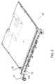
- FIG. 2is a perspective view of a line module component of the telecommunications device of FIG. 1 .
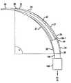
- FIG. 3Ais a perspective view of a fiber bender according to an embodiment of the invention.
- FIG. 3Bis a side elevational view of the fiber bender of FIG. 3A with an optical fiber disposed therein.
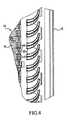
- FIG. 4is a sectional view of the optical fiber management system taken along line 4 — 4 of FIG. 1 with the connector boots and optical fiber cables not shown for clarity.
- FIGS. 5A-Care alternate embodiments of the fiber bender invention which accommodate two adjacent optical fibers.
- FIG. 5Dis an alternate embodiment of the fiber bender of FIG. 3 A.
- FIG. 5Eis the embodiment of FIG. 3A shown next to FIGS. 5A-D for comparative purposes.
- FIGS. 1-5EDescription will now be given of the invention with reference to FIGS. 1-5E. It should be noted that the figures are exemplary in nature and are meant in no way to limit the scope of the invention.
- FIG. 1depicts a schematic of a typical telecommunications networking device 5 usable in an optical network.
- Device 5includes a chassis 10 which has an openable door 12 shown in broken view. Within the chassis is disposed some support structure (not shown) such as shelving, hooks, etc., for supporting a series of circuit boards or line modules 14 .
- support structuresuch as shelving, hooks, etc.
- line moduleswere provided with eight optical transceivers each with their respective optical fibers being mounted internal to the faceplate of the line module.
- the new-standard of line modulesis now being provided with sixteen optical transceivers in a faceplate mounted external interconnect scheme.
- FIG. 2shows in perspective a typical modem line module 14 . It is provided with sixteen female LC connectors 15 mounted on the faceplate 14 A of the line module. Each female LC connector 15 has two receptacles, each one adapted to receive one optical fiber 16 (see FIG. 1) having a corresponding male LC connector (not shown) at its end. Each female LC connector 15 is respectively connected to an optical transceiver 19 . Transceivers 19 are bi-directional; consequently, two optical fibers 16 are required for each transceiver (one for incoming signals and the other for outgoing signals).
- Line module 14also includes one or more retaining levers 17 which secure the line module inside chassis 10 of networking device 5 .
- the device of FIG. 1has a number of line modules 14 disposed inside chassis 10 .
- Each line modulerequires up to 32 optical fibers 16 to be connected to LC connectors 15 .
- the devicecould require as many as 512 optical fibers 16 .
- the chassisis provided with cable routers 18 at the top and/or the bottom (not shown) of the inside of the chassis.
- optical fibers 16are routed in groups around cable routers 18 so as to keep them relatively segregated and orderly.
- optical fibers 16 from one line modulecan interfere with those of a neighboring line module. Further, and more importantly, the optical fibers must be made to lie flat and run substantially along the faceplate of their line modules so that a) the closing of the chassis door does not crush and break the optical fibers, and b) a technician may service one line module without damaging or disrupting the optical fibers of an adjacent line module.
- an embodiment of the fiber optic management systemincludes a fiber bender 20 shown in FIG. 3; in FIG. 3A, it is shown by itself in perspective, and in FIG. 3B, it is shown in side elevation with an associated optical fiber.
- Fiber bender 20includes an arcuate or horn-shaped main body having a first end 22 and a preferably larger second end 24 .
- a central channel 23is formed on the side of the main body and is surrounded by walls 27 ; in such a configuration, the cross-section of the main body is substantially in the shape of the letter “C” or a semi-circle, or similar such geometric shape.
- channel 23 on the side of the main body rather than the top of the main bodyenables fiber bender 20 to support the entire length of the bent portion of the fiber from both sides via walls 27 . In this way, fiber bender 20 serves to maintain the proper bend radius throughout the entire length of the bent portion of the fiber.
- the standard optical fiber 16 that is being fitted inside fiber bender 20consists of the optical fiber cable itself, a connector boot 16 A, and a male LC connector 16 B.
- Connector 16 Bis matingly engageable with female LC connector 15 shown in FIG. 2 .
- Connector boot 16 Ais provided around the fiber cable before it terminates in the male LC connector 16 B to provide strain relief and protection for the cable as it emerges from the rear portion of LC connector 16 B.
- the first end 22 of fiber bender 20is adapted (i.e., shaped, dimensioned, designed, etc.) to receive the proximal or non-connector side of optical fiber 16 as shown in FIG. 3 B.
- Second end 24is preferably larger in width than first end 22 and is adapted to receive part of connector boot 16 A. It is intended that fiber bender 20 cover part of connector boot 16 A so that the bending of the fiber can begin as close to the connector 16 B as possible, thereby reducing the amount the fiber sticks out perpendicularly from faceplate 14 A.
- the fiber bendernot be fitted around the extreme lowermost portion of connector boot 16 A.
- the two female ports of a single LC connector 15are extremely close together; there is barely enough room for two optical fibers 16 to be connected to the same LC connector 15 . If the fiber benders of the two optical fibers were placed at the lowermost end of their respective connector boots 16 A, the two fiber benders would add significantly to the overall diameter of the optical fibers, and the fibers would push against each other when they were connected to the same connector. This situation is unacceptable as it would produce undesirable stresses on the optical transceiver and the fibers themselves.
- fiber bender 20One of the functions of fiber bender 20 is to bend the optical fiber away from the chassis door 12 so that the fiber will not stick out too far from faceplate 14 A and thus be crushed when the door is closed. Fiber bender 20 minimizes the profile of the optical fiber. If fiber bender 20 is placed too high on the optical fiber (i.e., too far away from the connector end of the fiber), then the profile of the fiber may not be reduced sufficiently to avoid a closing chassis door. By inserting the connector boot 16 A until it abuts shoulder 26 , the profile of the optical fiber is sufficiently reduced in an easily repeatable manner.
- Fiber bender 20is an arc-shaped device that subtends an angle a as shown in FIG. 3 B. Since the optical fiber initially emerges from faceplate 14 A perpendicular to faceplate 14 A, and since it is desired to bend the fiber to be parallel to faceplate 14 A, it is preferred that the fiber bender bend the fiber approximately 90°. It is borne in mind by the inventors that optical fiber, a standard article of commerce, has an industry-recommended minimum bend radius which is set to avoid breaking the optical fiber. As such, one skilled in the art will be cognizant of this minimum bend radius and will appreciate that the inventive fiber bender 20 is dimensioned so as not to bend an optical fiber any smaller than the industry-recommended bend radius.
- bender 20is provided with one or more projections 28 , preferably along the tops of walls 27 . These projections engage the cable or the connector boot (depending upon where the projections are formed on the bender) and help prevent the optical fiber from falling out of central channel 23 .
- the main body of fiber bender 20is preferably made from a resilient material such as metal, plastic, or a similar material that allows for resiliency of the part as it slips over the boot.
- the materialis sufficiently stiff to withstand inadvertent impacts by technicians, however at least the second end 24 of the bender is resilient so that the connector boot of the optical fiber can be friction fitted therein.
- FIGS. 1 and 4The overall inventive fiber management system can be seen in FIGS. 1 and 4.
- FIG. 1it is shown that some of the fibers 16 may be routed vertically upwards and that some of the fibers 16 may be routed vertically downwards.
- FIG. 4demonstrates the flexibility of the inventive system (connector boots and the fibers themselves are not shown for clarity).
- FIG. 4is a sectional view of the overall system of FIG. 1 taken along line IV—IV.
- fiber benders 20are disposed a predetermined distance from the faceplate 14 A of line module 14 , owing to connector boot 16 A abutting shoulder 26 of the fiber bender.
- every other fiber bender in FIG. 4can be rotated slightly off the exact straight vertical line of line IV—IV (in FIG. 4, it is the lower fiber bender of each pair; of course, it could just as easily be the upper fiber bender). If the fibers were all aligned precisely vertically, the lower fiber of each pair of fibers would be overlapping its upper fiber neighbor. Such a configuration may be undesirable, as the overall profile of the fibers is increased and the chassis door may impact on the overlapping fiber. Also, by bending the lower fiber with the fiber bender and then bending the lower bent fiber over the upper bent fiber, undue stress may be created in the lower fiber. Consequently, the lower fiber is preferably rotated slightly off the vertical so as to avoid interfering with its neighboring fiber.
- channel 23 on the side of the main body of the fiber bendermakes this rotation extremely easy. Providing channel 23 on the side rather than the top also insures that any inadvertent impacts with the optical fiber will strike the fiber bender and not the fiber itself; if the channel were formed in the top part of the main body, the fiber may be exposed to damaging impacts.
- FIGS. 5A-DAlternate embodiments of the inventive fiber bender are shown in FIGS. 5A-D.
- Fiber benders 120 , 220 , and 320differ slightly from the first embodiment of the bender 20 in that they accommodate both optical fibers for a given two-port LC connector.
- bender 120has a first end 122 for receiving two optical fiber cables, and second end 124 is adapted to receive two connector boots 16 A.
- Central channel 123is wide enough to accommodate two fibers 16 .
- At least one fin 125may be provided to give bender 120 sufficient stiffness.
- Transverse stopper 126prevents the connector boots from being inserted too far into bender 120 while providing lateral support for the bender.
- Projections 128function similarly to projections 28 of the embodiment described in FIG. 3 .
- FIG. 5Bdepicts another alternate embodiment of the fiber bender.
- Bender 220is also a two-fiber bender, having first end 222 and second end 224 as before.
- a central divider 221is provided in channel 223 to keep the two optical fibers disposed in channel 223 reasonably apart from one another. Walls 227 come up much higher over central channel 223 so that they effectively act as projections which retain the optical fibers inside channel 223 .
- a support rib 225is provided for rigidity.
- Bender 320 of FIG. 5Cis similar to bender 120 of FIG. 5A with some slight modifications.
- Central divider 321is provided at second end 324 to keep the connector boots properly spaced apart, while central divider post 321 A is provided at first end 321 to separate the optical fiber cables.
- Support rib 325is provided similar to rib 225 of FIG. 5 B.
- Walls 327 and projections 328are provided similar to walls 127 and projections 128 of FIG. 5 A.
- Transverse rib 326provides lateral support for the bender and allows the plastic injection mold tool to be simpler and more cost effective.
- FIG. 5Dshows a single fiber bender 420 which is similar in many respects to bender 20 of FIG. 3 .
- the various parts of FIG. 5Dcorrespond to those referenced in FIG. 3 but with reference numerals in the 400s; e.g., ends 422 and 424 are substantially similar to ends 22 and 24 of FIG. 3, channel 423 and shoulder 426 are similar to channel 23 and shoulder 26 of FIG. 3, and walls 427 and projections 428 are similar to walls 27 and 28 .
- Fiber bender 420adds core cuts 429 (removed material) in channel 423 below projections 428 . The provision of core cuts 429 serves to facilitate tooling and injection molding.
Landscapes
- Physics & Mathematics (AREA)
- General Physics & Mathematics (AREA)
- Optics & Photonics (AREA)
- Light Guides In General And Applications Therefor (AREA)
Abstract
Description
Claims (33)
Priority Applications (2)
| Application Number | Priority Date | Filing Date | Title |
|---|---|---|---|
| US09/916,980US6674951B1 (en) | 2001-07-27 | 2001-07-27 | Optical fiber management system and method and fiber bender thereof |
| US10/698,626US6959139B2 (en) | 2001-07-27 | 2003-11-03 | Optical fiber management system and method and fiber bender thereof |
Applications Claiming Priority (1)
| Application Number | Priority Date | Filing Date | Title |
|---|---|---|---|
| US09/916,980US6674951B1 (en) | 2001-07-27 | 2001-07-27 | Optical fiber management system and method and fiber bender thereof |
Related Child Applications (1)
| Application Number | Title | Priority Date | Filing Date |
|---|---|---|---|
| US10/698,626DivisionUS6959139B2 (en) | 2001-07-27 | 2003-11-03 | Optical fiber management system and method and fiber bender thereof |
Publications (1)
| Publication Number | Publication Date |
|---|---|
| US6674951B1true US6674951B1 (en) | 2004-01-06 |
Family
ID=29737303
Family Applications (2)
| Application Number | Title | Priority Date | Filing Date |
|---|---|---|---|
| US09/916,980Expired - LifetimeUS6674951B1 (en) | 2001-07-27 | 2001-07-27 | Optical fiber management system and method and fiber bender thereof |
| US10/698,626Expired - LifetimeUS6959139B2 (en) | 2001-07-27 | 2003-11-03 | Optical fiber management system and method and fiber bender thereof |
Family Applications After (1)
| Application Number | Title | Priority Date | Filing Date |
|---|---|---|---|
| US10/698,626Expired - LifetimeUS6959139B2 (en) | 2001-07-27 | 2003-11-03 | Optical fiber management system and method and fiber bender thereof |
Country Status (1)
| Country | Link |
|---|---|
| US (2) | US6674951B1 (en) |
Cited By (7)
| Publication number | Priority date | Publication date | Assignee | Title |
|---|---|---|---|---|
| US20030165298A1 (en)* | 2002-03-01 | 2003-09-04 | Ngo Hung Viet | Angled optical connector adapter mounting assembly |
| US20040136657A1 (en)* | 2003-01-15 | 2004-07-15 | Fci Americas Technology, Inc. | Guide boot for a fiber-optic cable |
| US20060133747A1 (en)* | 2004-12-22 | 2006-06-22 | Juergen Mueller | Multi-fiber cable for efficient manageability of optical system |
| US20080310798A1 (en)* | 2007-06-18 | 2008-12-18 | Joseph Todd Cody | Fiber optic plug assembly with boot and crimp band |
| US7676132B1 (en)* | 2002-08-06 | 2010-03-09 | Cisco Technology, Inc. | Bend radius control |
| US20120057840A1 (en)* | 2010-07-06 | 2012-03-08 | Airbus Operations Limited | Apparatus for providing support for an optical fibre |
| TWI561867B (en)* | 2007-01-19 | 2016-12-11 | Adc Telecommunications Inc | Overehead cable management system, overhead cable terminaltion device, method of terminating a cable, and facility arrangement |
Families Citing this family (34)
| Publication number | Priority date | Publication date | Assignee | Title |
|---|---|---|---|---|
| US6760531B1 (en) | 1999-03-01 | 2004-07-06 | Adc Telecommunications, Inc. | Optical fiber distribution frame with outside plant enclosure |
| US7142764B2 (en) | 2003-03-20 | 2006-11-28 | Tyco Electronics Corporation | Optical fiber interconnect cabinets, termination modules and fiber connectivity management for the same |
| US7198409B2 (en) | 2003-06-30 | 2007-04-03 | Adc Telecommunications, Inc. | Fiber optic connector holder and method |
| US7233731B2 (en) | 2003-07-02 | 2007-06-19 | Adc Telecommunications, Inc. | Telecommunications connection cabinet |
| US6983095B2 (en) | 2003-11-17 | 2006-01-03 | Fiber Optic Network Solutions Corporation | Systems and methods for managing optical fibers and components within an enclosure in an optical communications network |
| US7369741B2 (en) | 2003-11-17 | 2008-05-06 | Fiber Optics Network Solutions Corp. | Storage adapter with dust cap posts |
| US7218827B2 (en) | 2004-06-18 | 2007-05-15 | Adc Telecommunications, Inc. | Multi-position fiber optic connector holder and method |
| US7194181B2 (en) | 2005-03-31 | 2007-03-20 | Adc Telecommunications, Inc. | Adapter block including connector storage |
| US7695197B2 (en)* | 2006-04-20 | 2010-04-13 | Tyco Electronics Corporation | Bend limiter |
| US7760984B2 (en) | 2006-05-04 | 2010-07-20 | Adc Telecommunications, Inc. | Fiber distribution hub with swing frame and wrap-around doors |
| US7389961B1 (en)* | 2006-11-15 | 2008-06-24 | Floyd Haws | Hose outlet support bracket |
| US8229265B2 (en) | 2007-11-21 | 2012-07-24 | Adc Telecommunications, Inc. | Fiber distribution hub with multiple configurations |
| ES2560802T3 (en) | 2008-08-27 | 2016-02-22 | Adc Telecommunications, Inc. | Fiber optic adapter with integrally molded bushing alignment structure |
| WO2010059623A1 (en) | 2008-11-21 | 2010-05-27 | Adc Telecommunications, Inc. | Fiber optic telecommunications module |
| CN102870021B (en) | 2010-03-02 | 2015-03-11 | 蒂安电子服务有限责任公司 | Fibre-optic telecommunication module |
| US20120217986A1 (en)* | 2011-02-24 | 2012-08-30 | International Business Machines Corporation | Module assembly holding workboard |
| US9417418B2 (en) | 2011-09-12 | 2016-08-16 | Commscope Technologies Llc | Flexible lensed optical interconnect device for signal distribution |
| RU2611105C2 (en) | 2011-10-07 | 2017-02-21 | Адс Телекоммьюникейшнз, Инк. | Fibre-optic cartridge, system and method |
| US9146362B2 (en) | 2012-09-21 | 2015-09-29 | Adc Telecommunications, Inc. | Insertion and removal tool for a fiber optic ferrule alignment sleeve |
| US9146374B2 (en) | 2012-09-28 | 2015-09-29 | Adc Telecommunications, Inc. | Rapid deployment packaging for optical fiber |
| NZ706687A (en) | 2012-09-28 | 2017-09-29 | Adc Telecommunications Inc | Fiber optic cassette |
| US9223094B2 (en) | 2012-10-05 | 2015-12-29 | Tyco Electronics Nederland Bv | Flexible optical circuit, cassettes, and methods |
| US9435975B2 (en) | 2013-03-15 | 2016-09-06 | Commscope Technologies Llc | Modular high density telecommunications frame and chassis system |
| WO2015116672A1 (en) | 2014-01-28 | 2015-08-06 | Adc Telecommunications, Inc. | Slidable fiber optic connection module with cable slack management |
| US9494758B2 (en) | 2014-04-03 | 2016-11-15 | Commscope Technologies Llc | Fiber optic distribution system |
| CN204359973U (en)* | 2015-01-21 | 2015-05-27 | 泰科电子(上海)有限公司 | The optical fiber connector |
| MX2017014377A (en) | 2015-05-15 | 2018-08-15 | Adc Telecommunications Shanghai Distrib Co Ltd | Alignment sleeve assembly and optical fibre adapter. |
| US10361507B2 (en)* | 2017-05-31 | 2019-07-23 | Zaytoun Industries | Device for protection of electronic device charging cord |
| US11409068B2 (en) | 2017-10-02 | 2022-08-09 | Commscope Technologies Llc | Fiber optic circuit and preparation method |
| US10665986B1 (en)* | 2019-04-01 | 2020-05-26 | Britney S. Prado | Reinforcement of mobile electronic device charging cables / electrical cords |
| US10845542B1 (en) | 2019-08-19 | 2020-11-24 | Afl Telecommunications Llc | Cable node transition assemblies |
| US12339511B2 (en) | 2020-03-31 | 2025-06-24 | Commscope Technologies Llc | Fiber optic cable management systems and methods |
| US11886029B2 (en) | 2021-03-10 | 2024-01-30 | Afl Telecommunications Llc | Systems and methods of managing cables in telecommunication systems |
| CN216251365U (en)* | 2021-04-30 | 2022-04-08 | 东莞讯滔电子有限公司 | cable connector assembly |
Citations (3)
| Publication number | Priority date | Publication date | Assignee | Title |
|---|---|---|---|---|
| US4372511A (en)* | 1980-12-08 | 1983-02-08 | Bell Telephone Laboratories, Incorporated | Optical fiber cable strain relief assembly |
| US5530787A (en)* | 1995-02-28 | 1996-06-25 | At&T Corp | Optical fiber guide for preventing sharp bends |
| US6236795B1 (en)* | 1999-06-07 | 2001-05-22 | E. Walter Rodgers | High-density fiber optic cable distribution frame |
Family Cites Families (9)
| Publication number | Priority date | Publication date | Assignee | Title |
|---|---|---|---|---|
| US5094552A (en)* | 1990-11-16 | 1992-03-10 | Amp Incorporated | Interlocking strain relief |
| GB9102006D0 (en)* | 1991-01-30 | 1991-03-13 | Lucas Ind Plc | Screening arrangement for connectors |
| US5347603A (en)* | 1993-06-14 | 1994-09-13 | Molex Incorporated | Right angle cable strain relief |
| US5461690A (en)* | 1994-07-29 | 1995-10-24 | At&T Ipm Corp. | Bend-limiting apparatus for a cable |
| US5640476A (en)* | 1995-07-14 | 1997-06-17 | Siecor Corporation | Guide sleeve for fiber optic cable |
| US5710851A (en)* | 1995-11-06 | 1998-01-20 | Amphenol Corporation | Strain relief system for a fiber optic connector |
| US6134370A (en)* | 1998-10-30 | 2000-10-17 | Siecor Operations, Llc | Fiber optic cable guide |
| US6554489B2 (en)* | 2001-03-28 | 2003-04-29 | Corning Cable Systems Llc | Fiber optic cable guide and method of application |
| US6629783B2 (en)* | 2001-07-06 | 2003-10-07 | Fci Americas Technology, Inc. | Fiber optic cable guide boot |
- 2001
- 2001-07-27USUS09/916,980patent/US6674951B1/ennot_activeExpired - Lifetime
- 2003
- 2003-11-03USUS10/698,626patent/US6959139B2/ennot_activeExpired - Lifetime
Patent Citations (3)
| Publication number | Priority date | Publication date | Assignee | Title |
|---|---|---|---|---|
| US4372511A (en)* | 1980-12-08 | 1983-02-08 | Bell Telephone Laboratories, Incorporated | Optical fiber cable strain relief assembly |
| US5530787A (en)* | 1995-02-28 | 1996-06-25 | At&T Corp | Optical fiber guide for preventing sharp bends |
| US6236795B1 (en)* | 1999-06-07 | 2001-05-22 | E. Walter Rodgers | High-density fiber optic cable distribution frame |
Cited By (15)
| Publication number | Priority date | Publication date | Assignee | Title |
|---|---|---|---|---|
| US20030165298A1 (en)* | 2002-03-01 | 2003-09-04 | Ngo Hung Viet | Angled optical connector adapter mounting assembly |
| US7029182B2 (en)* | 2002-03-01 | 2006-04-18 | Fci Americas Technology, Inc. | Angled optical connector adapter mounting assembly |
| US7676132B1 (en)* | 2002-08-06 | 2010-03-09 | Cisco Technology, Inc. | Bend radius control |
| US20050058404A1 (en)* | 2003-01-15 | 2005-03-17 | Fci Americas Technology, Inc. | Guide boot for a fiber-optic cable |
| WO2004065999A3 (en)* | 2003-01-15 | 2005-04-28 | Fci Americas Technology Inc | Guide boot for a fiber-optic cable |
| US6932515B2 (en) | 2003-01-15 | 2005-08-23 | Fci Americas Technology, Inc. | Guide boot for a fiber-optic cable |
| US6817780B2 (en)* | 2003-01-15 | 2004-11-16 | Fci Americas Technology, Inc. | Guide boot for a fiber-optic cable |
| US20040136657A1 (en)* | 2003-01-15 | 2004-07-15 | Fci Americas Technology, Inc. | Guide boot for a fiber-optic cable |
| US20060133747A1 (en)* | 2004-12-22 | 2006-06-22 | Juergen Mueller | Multi-fiber cable for efficient manageability of optical system |
| US7298946B2 (en) | 2004-12-22 | 2007-11-20 | Hewlett-Packard Development Company, L.P. | Multi-fiber cable for efficient manageability of optical system |
| TWI561867B (en)* | 2007-01-19 | 2016-12-11 | Adc Telecommunications Inc | Overehead cable management system, overhead cable terminaltion device, method of terminating a cable, and facility arrangement |
| US20080310798A1 (en)* | 2007-06-18 | 2008-12-18 | Joseph Todd Cody | Fiber optic plug assembly with boot and crimp band |
| US7628545B2 (en) | 2007-06-18 | 2009-12-08 | Corning Cable Systems Llc | Fiber optic plug assembly with boot and crimp band |
| US20120057840A1 (en)* | 2010-07-06 | 2012-03-08 | Airbus Operations Limited | Apparatus for providing support for an optical fibre |
| US8311381B2 (en)* | 2010-07-06 | 2012-11-13 | Airbus Operations Limited | Apparatus for providing support for a portion of an optical fibre extending from a substrate |
Also Published As
| Publication number | Publication date |
|---|---|
| US20040165852A1 (en) | 2004-08-26 |
| US6959139B2 (en) | 2005-10-25 |
Similar Documents
| Publication | Publication Date | Title |
|---|---|---|
| US6674951B1 (en) | Optical fiber management system and method and fiber bender thereof | |
| US10527809B2 (en) | Telecommunications connection cabinet | |
| EP2149063B1 (en) | Fiber optic connector holders | |
| US9703062B2 (en) | Aggregator for a switch rack system | |
| CN101233436B (en) | Cable management panel with rear entry | |
| US8428418B2 (en) | Fiber optic adapter plate and cassette | |
| EP1766452B1 (en) | Telecommunications connection cabinet with holder for storing fiber optic connectors and corresponding method | |
| US20070280619A1 (en) | Multi-directional optical splice organizer | |
| US11740422B2 (en) | Interconnect system | |
| US20020122652A1 (en) | Optical fiber cable routing guide | |
| US20220137315A1 (en) | Track device for a telecommunications product | |
| EP4508474A1 (en) | Adapter configured to permit a heat shrink splice holder portion of a fiber splice cassette to hold a mechanical crimp splice protector | |
| EP4204882A1 (en) | Telecommunications panel | |
| EP3762752B1 (en) | High density optical fiber distribution sub-rack | |
| HK1100699B (en) | Telecommunications connection cabinet with holder for storing fiber optic connectors and corresponding method |
Legal Events
| Date | Code | Title | Description |
|---|---|---|---|
| AS | Assignment | Owner name:CIENA CORPORATION, MARYLAND Free format text:ASSIGNMENT OF ASSIGNORS INTEREST;ASSIGNORS:ERWIN, CHARLES MATTHEW;GEHRKE, GARY CURTIS;PARASNIS, NARASINHA CHANDRAKANT;REEL/FRAME:012048/0569 Effective date:20010725 | |
| STCF | Information on status: patent grant | Free format text:PATENTED CASE | |
| FPAY | Fee payment | Year of fee payment:4 | |
| FPAY | Fee payment | Year of fee payment:8 | |
| AS | Assignment | Owner name:DEUTSCHE BANK AG NEW YORK BRANCH, NEW YORK Free format text:SECURITY INTEREST;ASSIGNOR:CIENA CORPORATION;REEL/FRAME:033329/0417 Effective date:20140715 | |
| AS | Assignment | Owner name:BANK OF AMERICA, N.A., AS ADMINISTRATIVE AGENT, NO Free format text:PATENT SECURITY AGREEMENT;ASSIGNOR:CIENA CORPORATION;REEL/FRAME:033347/0260 Effective date:20140715 | |
| FPAY | Fee payment | Year of fee payment:12 | |
| AS | Assignment | Owner name:CIENA CORPORATION, MARYLAND Free format text:RELEASE BY SECURED PARTY;ASSIGNOR:DEUTSCHE BANK AG NEW YORK BRANCH;REEL/FRAME:050938/0389 Effective date:20191028 | |
| AS | Assignment | Owner name:BANK OF AMERICA, N.A., AS COLLATERAL AGENT, ILLINO Free format text:PATENT SECURITY AGREEMENT;ASSIGNOR:CIENA CORPORATION;REEL/FRAME:050969/0001 Effective date:20191028 | |
| AS | Assignment | Owner name:CIENA CORPORATION, MARYLAND Free format text:RELEASE BY SECURED PARTY;ASSIGNOR:BANK OF AMERICA, N.A.;REEL/FRAME:065630/0232 Effective date:20231024 |