US6674424B1 - Method and apparatus for inputting information including coordinate data - Google Patents
Method and apparatus for inputting information including coordinate dataDownload PDFInfo
- Publication number
- US6674424B1 US6674424B1US09/698,031US69803100AUS6674424B1US 6674424 B1US6674424 B1US 6674424B1US 69803100 AUS69803100 AUS 69803100AUS 6674424 B1US6674424 B1US 6674424B1
- Authority
- US
- United States
- Prior art keywords
- predetermined
- plane
- image
- coordinate
- extracted
- Prior art date
- Legal status (The legal status is an assumption and is not a legal conclusion. Google has not performed a legal analysis and makes no representation as to the accuracy of the status listed.)
- Expired - Lifetime, expires
Links
Images


Classifications
- G—PHYSICS
- G06—COMPUTING OR CALCULATING; COUNTING
- G06F—ELECTRIC DIGITAL DATA PROCESSING
- G06F3/00—Input arrangements for transferring data to be processed into a form capable of being handled by the computer; Output arrangements for transferring data from processing unit to output unit, e.g. interface arrangements
- G06F3/01—Input arrangements or combined input and output arrangements for interaction between user and computer
- G06F3/03—Arrangements for converting the position or the displacement of a member into a coded form
- G06F3/041—Digitisers, e.g. for touch screens or touch pads, characterised by the transducing means
- G06F3/042—Digitisers, e.g. for touch screens or touch pads, characterised by the transducing means by opto-electronic means
- G06F3/0428—Digitisers, e.g. for touch screens or touch pads, characterised by the transducing means by opto-electronic means by sensing at the edges of the touch surface the interruption of optical paths, e.g. an illumination plane, parallel to the touch surface which may be virtual
Definitions
- the present inventionrelates to a method and apparatus for inputting information including coordinate data. More particularly, the present invention relates to a method and apparatus for inputting information including coordinate data of a location of a coordinate input member, such as a pen, a human finger, etc., on an image displayed on a relatively large screen.
- a coordinate input membersuch as a pen, a human finger, etc.
- presentation systemselectronic copy boards, or electronic blackboard systems provided with a relatively large screen display device, such as a plasma display panel, a rear projection display, etc.
- Certain type of presentation systemsalso provide a touch input device disposed in front of a screen for inputting information related to the image displayed on the screen.
- a touch input deviceis also referred as an electronic tablet, an electronic pen, etc.
- a touch input devicedetects and inputs the touching motion and the coordinates of the touched location.
- the touch input devicerepetitively detects and inputs a plurality of coordinates as a locus of the drawn line.
- Japanese Laid-Open Patent Publication No. 11-85376describes a touch input apparatus provided with light reflecting devices disposed around a display screen, light beam scanning devices, and light detectors.
- the light reflecting devicehas a characteristic to reflect incident light toward a direction close to the incident light.
- scanning light beams emitted by the light beam scanning devicesare reflected by the light reflecting devices, and then received by the light detectors.
- a coordinate input membersuch as a pen, a user's finger, etc.
- touches the surface of the screen at a locationthe coordinate input member interrupts the path of the scanning light beams, and thereby the light detector is able to detect the touched location as a missing of the scanning light beams at the touched location.
- the scanning light beamsare desired to be thin and to scan on a plane close enough to the screen.
- the contorted surfacemay interfere with the transmission of the scanning light beams, and consequently a coordinate input operation might be impaired.
- a double-click operationmight not be properly detected, free hand drawing lines and characters might be erroneously detected, and so forth.
- Japanese Laid-Open Patent Publication No. 61-196317describes a touch input apparatus provided with a plurality of television cameras.
- the plurality of television camerasdetect three-dimensional coordinates of a moving object, such as a pen, as a coordinate input member. Because the apparatus detects three-dimensional coordinates, the plurality of television cameras are desirable to capture images of the moving object at a relatively high frame rate.
- a touch input apparatusprovided with an electro magnetic tablet and an electromagnetic stylus is known.
- a location of the stylusis detected based on electromagnetic induction between the tablet and the stylus. Therefore, a distance between the tablet and the stylus tends to be limited in a rather short distance, for example, eight millimeters; otherwise a large size stylus or a battery powered stylus is used.
- an object of the present inventionis to provide a novel method and apparatus that can input information including coordinate data even when the surface of a display screen is contorted to a certain extent and without using a light scanning device.
- Another object of the present inventionis to provide a novel method and apparatus that can input information including coordinate data using a plurality of coordinate input members, such as a pen, a human finger, a stick, a rod, a chalk, etc.
- Another object of the present inventionis to provide a novel method and apparatus that can input information including coordinate data with a plurality of background devices, such as a chalkboard, a whiteboard, etc., in addition to a display device, such as a plasma display panel, a rear projection display.
- a display devicesuch as a plasma display panel, a rear projection display.
- the present inventionprovides a method, computer readable medium and apparatus for inputting information including coordinate data that include extracting a predetermined object from an image including the predetermined object above a plane, detecting a motion of the predetermined object while the predetermined object is in a predetermined distance from the plane, and determining to input predetermined information.
- FIG. 1is a schematic view illustrating a coordinate data input system as an example configured according to the present invention
- FIG. 2is an exemplary block diagram of a control apparatus of the coordinate data input system of FIG. 1;
- FIG. 3is a diagram illustrating a method for obtaining coordinates where a coordinate input member contacts a display panel
- FIG. 4is a magnified view of the wide-angle lens and the CMOS image sensor of FIG. 3;
- FIG. 5is a diagram illustrating a tilt of the surface of the display panel to the CMOS image sensor
- FIG. 6is a flowchart illustrating operational steps for practicing a coordinate data inputting operation in the coordinate data input system of FIG. 1 as an example configured according to the present invention
- FIG. 7is a diagram illustrating an image captured by the first electronic camera of FIG. 1;
- FIG. 8is a diagram illustrating an image captured by the first electronic camera when an input pen distorts the surface of a display panel
- FIG. 9is a flowchart illustrating operational steps for practicing a coordinate data inputting operation as another example configured according to the present invention.
- FIG. 10is a diagram illustrating an image captured by the first electronic camera when an input pen tilts to the surface of a display panel
- FIG. 11is a diagram illustrating an image having an axial symmetry pen captured by the first electronic camera
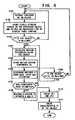
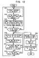
- FIG. 12is a flowchart illustrating operational steps for practicing a coordinate data inputting operation as another example configured according to the present invention.
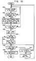
- FIG. 13is a flowchart illustrating operational steps for practicing a coordinate data inputting operation as another example configured according to the present invention.
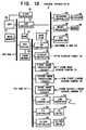
- FIG. 14is a flowchart illustrating operational steps for practicing a coordinate data inputting operation as another example configured according to the present invention.
- FIG. 15is a flowchart illustrating operational steps for practicing a coordinate data inputting operation as another example configured according to the present invention.
- FIG. 16Ais a diagram illustrating an image captured by the first electronic camera and an output limitation of the image
- FIG. 16Bis a diagram illustrating an image captured by the first electronic camera and a displaced output limitation of the image
- FIG. 17is a schematic view illustrating a coordinate data input system as another example configured according to the present invention.
- FIG. 18is an exemplary block diagram of a control apparatus of the coordinate data input system of FIG. 17 configured according to the present invention.
- FIG. 19is a diagram illustrating an analog signal waveform output from a linear sensor camera
- FIG. 20is a flowchart illustrating operational steps for practicing a coordinate data inputting operation in the coordinate data input system of FIG. 17 as an example configured according to the present invention
- FIG. 21is a flowchart illustrating operational steps for practicing a coordinate data inputting operation in the coordinate data input system of FIG. 17 as another example configured according to the present invention
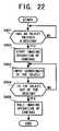
- FIG. 22is a flowchart illustrating operational steps for practicing a coordinate data inputting operation in the coordinate data input system of FIG. 17 as another example configured according to the present invention
- FIG. 23is a flowchart illustrating operational steps for practicing a coordinate data inputting operation in the coordinate data input system of FIG. 1 as another example configured according to the present invention
- FIG. 24is a diagram illustrating an image captured by the first electronic camera in the coordinate data input system of FIG. 1;
- FIG. 25is an exemplary network system including the coordinate data input systems of FIG. 1 and FIG. 17 .
- FIG. 1is a schematic view illustrating a coordinate data input system 1 S as an example configured according to the present invention.
- the coordinate data input system 1 Sincludes a coordinate data input apparatus 1 and a control apparatus 2 .
- the coordinate data input apparatus 1includes a first electronic camera 10 , a second electronic camera 11 , and a display panel 12 .
- the display panel 12displays an image with, for example, a 48 by 36 inch screen (diagonally 60 inches) and 1024 by 768-pixel resolution, which is referred as an XGA screen.
- a plasma display panel, a rear projection display, etc.may be used as the display panel 12 .
- Each of the first electronic camera 10 and the second electronic camera 11implements a two-dimensional imaging device with a resolution that enables such as a selecting operation of an item in a menu window, a drawing operation of free hand lines, letters, etc.
- a two-dimensional imaging deviceis also referred as an area sensor.
- the two-dimensional imaging devicepreferably has variable output frame rate capability.
- the two-dimensional imaging devicealso preferably has a random access capability that allows any imaging cell therein randomly accessed to obtain an image signal from the cell. Such a random access capability is sometimes also referred to as random addressability.
- CMOS sensorcomplementary metal oxide semiconductor sensor
- the electronic camera 10also includes a wide-angle lens 50 which covers around 90 degrees or wider angle and an analog to digital converter.
- the electronic camera 11also includes a wide-angle lens 52 which covers around 90 degrees or wider angle and an analog to digital converter.
- the first electronic camera 10is disposed at a upper corner of the display panel 12 and such that an optical axis of the wide-angle lens 50 forms an angle of approximately 45 degrees with the horizontal edge of the display panel 12 .
- the second electronic camera 11is disposed at the other upper corner of the display panel 12 and such that the optical axis of the wide-angle lens 52 forms an angle of approximately 45 degrees with the horizontal edge of the display panel 12 .
- each of the electronic cameras 10 and 11is disposed approximately parallel to a display screen surface of the display panel 12 .
- the electronic cameras 10 and 11can capture whole the display screen surface of the display panel 12 , respectively.
- Each of the captured imagesis converted into digital data, and the digital image data is then transmitted to the control apparatus 2 .
- FIG. 2is an exemplary block diagram of the control apparatus 2 of the coordinate data input system 1 S of FIG. 1 .
- the control apparatus 2includes a central processing unit (CPU) 20 , a main memory 21 , a clock generator 22 , a bus controller 23 , a read only memory (ROM) 24 , a peripheral component interconnect (PCI) bridge 25 , a cache memory 26 , a hard disk 27 , a hard disk controller (HD controller) 28 , a display controller 29 , a first image processing circuit 30 , and a second image processing circuit 31 .
- CPUcentral processing unit
- main memory 21main memory
- a clock generator 22the control apparatus 2
- ROMread only memory
- PCIperipheral component interconnect
- the control apparatus 2also includes a local area network controller (LAN controller) 32 , a LAN interface 33 , a floppy disk controller (FD controller) 34 , a FD drive 35 , a compact disc read only memory controller (CD-ROM controller) 36 , a CD-ROM drive 37 , a keyboard controller 38 , a mouse interface 39 , a real time clock generator (RTC generator) 40 , a CPU bus 41 , a PCI bus 42 , an internal X bus 43 , a keyboard 44 , and a mouse 45 .
- LAN controllerlocal area network controller
- FD controllerfloppy disk controller
- CD-ROM controllercompact disc read only memory controller
- the CPU 20executes a boot program, a basic input and output control system (BIOS) program stored in the ROM 24 , an operating system (OS), application programs, etc.
- the main memory 21may be structured by, e.g., a dynamic random access memory (DRAM), and is utilized as a work memory for the CPU 20 .
- the clock generator 22may be structured by, for example, a crystal oscillator and a frequency divider, and supplies a generated clock signal to the CPU 20 , the bus controller 23 , etc., to operate those devices at the clock speed.
- the bus controller 23controls data transmission between the CPU bus 41 and the internal X bus 43 .
- the ROM 24stores a boot program, which is executed immediately after the coordinate data input system 1 S is turned on, device control programs for controlling the devices included in the system 1 S, etc.
- the PCI bridge 25is disposed between the CPU bus 41 and the PCI bus 42 and transmits data between the PCI bus 42 and devices connected to the CPU bus 41 , such as the CPU 20 through the use of the cache memory 26 .
- the cache memory 26may be configured by, for example, a DRAM.
- the hard disk 27stores system software such as an operating system, a plurality of application programs, various data for multiple users of the coordinate data input system 1 S.
- the hard disk (HD) controller 28implements a standard interface, such as a integrated device electronics interface (IDE interface), and transmits data between the PCI bus 42 and the hard disk 27 at a relatively high speed data transmission rate.
- IDE interfaceintegrated device electronics interface
- the display controller 29converts digital letter/character data and graphic data into an analog video signal, and controls the display panel 12 of the coordinate data input apparatus 1 so as to display an image of the letters/characters and graphics thereon according to the analog video signal.
- the first image processing circuit 30receives digital image data output from the first electronic camera 10 through a digital interface, such as an RS-422 interface.
- the first image processing circuit 30then executes an object extraction process, an object shape recognition process, a motion vector detection process, etc. Further, the first image processing circuit 30 supplies the first electronic camera 10 with a clock signal and an image transfer pulse via the above-described digital interface.
- the second image processing circuit 31receives digital image data output from the second electronic camera 11 through a digital interface, such as also an RS-422 interface.
- the second image processing circuit 31is configured as the substantially same hardware as the first image processing circuit 30 , and operates substantially the same as the first image processing circuit 30 operates. That is, the second image processing circuit 31 also executes an object extraction process, an object shape recognition process, a motion vector detection process, and supplies a clock signal and an image transfer pulse to the second electronic camera 11 as well.
- the clock signal and the image transfer pulse supplied to the first electronic camera 10 and those signals supplied to the second electronic camera 11are maintained in synchronization.
- the LAN controller 32controls communications between the control apparatus 2 and external devices connected to a local area network, such as an Ethernet, via the LAN interface 33 according to the protocol of the network.
- a local area networksuch as an Ethernet
- IEEE 802.3 standardmay be used.
- the FD controller 34transmits data between the PCI bus 42 and the FD drive 35 .
- the FD drive 35reads and writes a floppy disk therein.
- the CD-ROM controller 36transmits data between the PCI bus 42 and the CD-ROM drive 37 .
- the CD-ROM drive 37reads a CD-ROM disc therein and sends the read data to the CD-ROM controller 36 .
- the CD-ROM controller 36 and the CD-ROM drive 37may be connected with an IDE interface.
- the keyboard controller 38converts serial key input signals generated at the keyboard 44 into parallel data.
- the mouse interface 39is provided with a mouse port to be connected with the mouse 45 and controlled by mouse driver software or a mouse control program.
- the coordinate data input apparatus 1functions as a data input device, and therefore the keyboard 44 and the mouse 45 may be omitted from the coordinate data input system 1 S in normal operations except for a moment during a maintenance operation for the coordinate data input system 1 S.
- the RTC generator 40generates and supplies calendar data, such as day, hour, and minute, etc., and is battery back-upped.
- FIG. 3is a diagram illustrating a method for obtaining coordinates where a coordinate input member contacts or comes close to the display panel 12 .
- the first electronic camera 10includes the wide-angle lens 50 and a CMOS image sensor 51
- the second electronic camera 11also includes the wide-angle lens 52 and a CMOS image sensor 53 .
- the first and second electronic cameras 10 and 11are disposed such that the optical axes of the wide-angle lenses 50 and 52 , i.e., the optical axes of incident lights to the cameras, are parallel to the display surface of the display panel 12 . Further, the first and second electronic cameras 10 and 11 are disposed such that each of the angles of view of the electronic cameras 10 and 11 covers substantially a whole area where the coordinate input member can come close and touch the display panel 12 .
- the symbol Ldenotes a distance between the wide-angle lens 50 and the wide-angle lens 52
- the symbol X-Linedenotes a line connecting the wide-angle lens 50 and the wide-angle lens 52 .
- the symbol A(x, y)denotes a point A where a coordinate input member comes close to or touches the display panel 12 and the coordinates (x, y) thereof The point A(x, y) is referred as a contacting point.
- the symbol ⁇ 1denotes an angle which the line X-line forms with a line connecting the wide-angle lens 50 and the contacting point A(x, y)
- the symbol ⁇ 2denotes an angle that the X-line forms with a line connecting the wide-angle lens 52 and the contacting point A(x, y).
- FIG. 4is a magnified view of the wide-angle lens 50 and the CMOS image sensor 51 of FIG. 3 .
- the symbol fdenotes a distance between the wide-angle lens 50 and the CMOS image sensor 51 .
- the symbol Qdenotes a point at which the optical axis of the wide-angle lens 50 intersects the CMOS image sensor 51 .
- the point Qis referred as an optical axis crossing point.
- the symbol Pdenotes a point where an image of the contacting point A(x, y) is formed on the CMOS image sensor 51 .
- the point Pis referred as a projected point P of the contacting point A(x, y).
- the symbol hdenotes a distance between the point P and the point Q.
- the symbol ⁇denotes an angle which the optical axis of the wide-angle lens 50 forms with the X-line, and the symbol ⁇ denotes an angle which the optical axis of the wide-angle lens 50 forms with a line connecting the contacting point A(x, y) and the point P.
- the angle ⁇ and the distance fare constant values, because these values are determined by a mounted mutual location of the wide-angle lens 50 and the CMOS image sensor 51 , and a mounted angle of the wide-angle lens 50 to the line X-line at a manufacturing plant. Therefore, when the distance h is given, the angle ⁇ 1 is solved. Regarding the second electronic camera 11 , similar equations are hold, and thus the angle ⁇ 2 is solved.
- the coordinates of the contacting point A(x, y)are calculated by the followings based on a principle of trigonometrical survey;
- Each of the CMOS image sensors 51 and 53has a two-dimensional array or a matrix of imaging picture elements (pixels) or imaging cells.
- the CMOS image sensors 51 and 53are disposed such that a side having the larger number of imaging cells is parallel to the surface of the display panel 12 .
- a coordinate axis along the direction having the larger number of imaging cellsis represented by Ycamera axis.
- a coordinate axis along the direction having a smaller number of imaging cells, i.e., the direction perpendicular to the Ycamera axisis represented by Xcamera axis.
- a line formed on the CMOS image sensors 51 and 53is hereinafter referred as “a formed line of the surface of the display panel 12 ,” “a projected line of the surface of the display panel 12 ,” or just simply “the surface of the display panel 12 .”
- FIG. 5is a diagram illustrating a tilt of the surface of the display panel 12 to the CMOS image sensors 51 and 53 .
- the tilting angle ⁇ to the Ycamera axisis obtained as follows.
- points A(x 1 c, y 1 c), B(x 2 c, y 2 c), C(x 3 c, y 3 c)are arbitrary points on the projected line of the surface of the display panel 12 .
- An angle ⁇ between a line connecting each point and the origin of the coordinate system and the Ycamera axisis stated as follows;
- ⁇ 1arctan( x 1 c/y 1 c ) (5)
- ⁇ 3arctan( x 3 c/y 3 c ) (7)
- the tilted angle ⁇is obtained as an average value of those angles
- a tilted coordinate systemwhich tilts angle ⁇ to the original coordinate system (Xcamera, Ycamera), may also be conveniently utilized to obtain a location of a coordinate input member and a motion vector thereof.
- the tilted coordinate systemis related to a rotation of the original coordinate system at angle ⁇ .
- the tilted coordinate systemis obtained by being rotated counterclockwise, and vice versa.
- FIG. 6is a flowchart illustrating operational steps for practicing a coordinate data inputting operation in the coordinate data input system 1 S of FIG. 1 as an example configured according to the present invention.
- the CMOS image sensor 51may not always have an appropriate image aspect ratio, or a ratio of the number of imaging cells in a direction to that in the other direction.
- the first electronic camera 10allows outputting the image signal captured by the CMOS image sensor 51 within a predetermined range from the surface of the display panel 12 in a direction perpendicular to the surface.
- the first electronic camera 10outputs digital image data in the predetermined range to the first image processing circuit 30 in the control apparatus 2 .
- the second electronic camera 11outputs digital image data in a predetermined range to the second image processing circuit 31 .
- the first image processing circuit 30extracts contours of an object as a coordinate input member from frame image data received from the first electronic camera 10 .
- the first image processing circuit 30first determines gradients of image density among the pixels by differentiation, and then extracts contours based on a direction and magnitude of the gradients of image density.
- the method described in Japanese Patent Publication No. 8-16931may also be applied for extracting an object as a coordinate input member from frame image data.
- the first image processing circuit 30measures plural distances between the object and the projected line of the surface of the display panel 12 on the CMOS image sensor 51 .
- the first image processing circuit 30counts pixels included between a point on the contours of the extracted object and a point on the projected line of the surface of the display panel 12 on the CMOS image sensor 51 .
- An image forming reduction ratio on the CMOS image sensor 51is fixed and a pixel pitch of the CMOS image sensor 51 (i.e., the interval between imaging cells) is known. As a result, the number of pixels between two points determines a distance between the two points.
- the first image processing circuit 30For measuring plural distances between the object and the surface of the display panel 12 , the first image processing circuit 30 counts pixels as regards plural distances between the contours of the extracted object and the projected line of the surface of the display panel 12 .
- step S 103the first image processing circuit 30 extracts the least number of pixels among the plural numbers of pixels counted for measuring plural distances in step S 102 .
- a symbol Nmindenotes the least number of pixels among the plural numbers of pixels. Consequently, the distance being the minimum value Nmin corresponds to a nearest point of the object to the surface of the display panel 12 .
- the first image processing circuit 30determines whether the minimum value Nmin is smaller than a predetermined number M 0 .
- step S 103When the minimum value Nmin is smaller than the predetermined number M 0 , i.e., YES in step S 103 , the process proceeds to step S 104 , and when the minimum value Nmin is not smaller than the predetermined number M 0 , i.e., NO in step S 103 , the process returns to step S 104 , and when the minimum value Nmin is not smaller than the predetermined number M 0 , i.e., NO in step S 103 , the process returns to step S 104 , and when the minimum value Nmin is not smaller than the predetermined number M 0 , i.e., NO in step S 103 , the process returns to step S 104 , and when the minimum value Nmin is not smaller than the predetermined number M 0 , i.e., NO in step S 103 , the process returns to step S 104 , and when the minimum value Nmin is not smaller than the predetermined number M 0 , i.e., NO in step S
- step S 104the first image processing circuit 30 calculates motion vectors regarding predetermined plural points on the extracted contours of the object including the nearest point to the display panel 12 . For this calculation, the first image processing circuit 30 uses the identical frame image data used for extracting the contours and the next following frame image data received from the first electronic camera 10 .
- the first image processing circuit 30obtains optical flows, i.e., velocity vectors, by calculating a rate of temporal change of a pixel image density.
- the first image processing circuit 30also obtains a rate of spatial change of image densities of pixels in the vicinity of the pixel used for calculating the rate of temporal change of the pixel image density.
- the motion vectorsare expressed on the coordinate system (Xcamera, Ycamera), which associates with the projected line of the surface of the display panel 12 on the CMOS image sensor 51 (i.e., Ycamera) and the coordinate perpendicular to the surface of the display panel 12 (i.e., Xcamera).
- FIG. 7is a diagram illustrating an image captured by the first electronic camera 10 .
- a thick lineillustrates the projected line of the surface of the display panel 12 on the CMOS image sensors 51 .
- the display panel 12includes a display area and a frame in circumference of and at approximately same level of the display screen surface. Therefore, the surface of the display panel 12 can also be the surface of the frame.
- the alternate long and short dash lineis drawn at a predetermined distance from the projected line of the surface of the display panel 12 .
- the predetermined distancecorresponds to the predetermined number M 0 of pixels at the step S 103 of FIG. 6, and the region limited by the predetermined distance is denoted by REGION FOR OBTAINING MOTION VECTORS.
- the linked plural linesillustrate a pen as the extracted contours of the object at the step S 101 of FIG. 6 .
- the nearest point of the pen to the display panel 12which is marked by the black dot at the tip of the pen in FIG. 7, is in the REGION FOR OBTAINING MOTION VECTORS. Accordingly, a calculation of motion vectors, which is executed at the step S 104 of FIG. 6, results in such as the motion vector and components thereof Vx and Vy as illustrated in FIG. 7 regarding the nearest point (black dot) of the pen.
- step S 105the CPU 20 stores motion vector components along the direction Xcamera of the calculated vectors, such as the component Vx illustrated in FIG. 7, in the main memory 21 .
- the CPU 20stores those vector components from each obtained frame image data in succession.
- the successively stored motion vector datais also referred as trace data.
- step S 106the CPU 20 determines whether the extracted object, such as the pen in FIG. 7, has made an attempt to input coordinates on the display panel 12 based on the trace data of motion vectors. A determining method is further described later.
- the processproceeds to step S 108 , and when the object has not made an attempt to input coordinates, i.e., No in step S 107 , the process branches to step S 109 .
- step S 108the CPU 20 measures the distance h between the optical axis crossing point Q and a projected point P of a contacting point A(x, y) of the object.
- the extracted objectis physically soft, such as a human finger, the extracted object may contact at an area rather than a point.
- the contacting point A(x, y)can be replaced with the center of the contacting area.
- the term contacting point A(x, y)is applied for not only a contacting state of the object and the display panel 12 , but also a state that the object is adjacent to the display panel 12 .
- a range from the optical axis crossing point Q to an end of the CMOS image sensor 51contains a fixed number (denoted by N 1 ) of pixels, which only depends upon relative locations of the wide-angle lens 50 and the CMOS image sensor 51 being disposed.
- a range from the point P to the end of the CMOS image sensor 51contains variable pixels (denoted by N 2 ), which varies depending upon the location of the contacting point A(x, y) of the object. Therefore, the range between the point Q and the point P contains
- step S 110the CPU 20 solves the angle ⁇ 1 by using the equations (1) and (2), with known quantities f and ⁇ , and the measured distance h. As regards image data received from the second electronic camera 11 , the CPU 20 solves the angle ⁇ 2 in a similar manner.
- step S 111the CPU 20 solves the coordinates x and y of the object on the display panel 12 by using the equations (3) and (4), with known quantities L, and the solved angles ⁇ 1 and ⁇ 2 .
- step S 109the CPU 20 determines whether the object is still within the predetermined region above the display panel 12 using the trace data of motion vector components Vx of the object.
- the processreturns to step S 104 to obtain motion vectors again, and when the object is out of the predetermined region, i.e., NO in step S 109 , the process returns to step
- the calculating operationsis executed by the CPU 20 .
- angles ⁇ 1 , ⁇ 2may also be solved by the first image processing circuit 30 and the second image processing circuit 31 , respectively, and then the obtained ⁇ 1 , ⁇ 2 are transferred to the CPU 20 to solve the coordinates x and y.
- the CPU 20may also execute the above-described contour extracting operation in step S 101 , the distance measuring operation in step S 102 , the least number extracting and comparing operation in steps S 103 and S 104 in place of the first image processing circuit 30 .
- the hard disk 27may initially store program codes, and the program codes are loaded to the main memory 21 for execution every time after the system 1 S is boot upped.
- the CPU 20When the coordinate data input system 1 S is in a writing input mode or a drawing input mode, the CPU 20 generates display data according to the obtained plural sets of coordinates x and y of the object, i.e., the locus data of the object, and sends the generated display data to the display controller 29 .
- the display controller 29displays an image corresponding to the locus of the object on the display panel 12 of the coordinate data input apparatus 1 .
- FIG. 8is a diagram illustrating an image captured by the first electronic camera 10 when an input pen distorts the surface of a display panel.
- the tip of the penis out of the frame due to the distortion or warp in the surface of the display panel caused by the pressure of the pen stroke.
- Intersections of the surface of the display panel 12 and the contours of the penare denoted by point A and point B.
- the middle point of the points A and Bmay be presumed or substantially equivalent to a nearest point of the pen as well as a literal sense of the nearest point, such as the black dot at the tip of the pen illustrated in FIG. 7 .
- FIG. 9is a flowchart illustrating operational steps for practicing a coordinate data inputting operation as another example configured according to the present invention. The method is also executed on the coordinate data input system 1 S of FIG. 1 .
- step S 201the first image processing circuit 30 or the CPU 20 extracts contours of an object as a coordinate input member from frame image data received from the first electronic camera 10 .
- step S 202the first image processing circuit 30 or the CPU 20 first extracts geometrical features of the shape of the extracted contours of the object.
- the first image processing circuit 30 or the CPU 20determines the position of the barycenter of the contours of the object, then measures distances from the barycenter to plural points on the extracted contours for all radial directions like the spokes of a wheel. Then, the CPU 20 extracts geometrical features of the contour shape of the object based on relations between each direction and the respective distance.
- Japanese Laid-Open Patent Publication No. 8-315152may also be referred for executing the above-stated character extraction method.
- the CPU 20compares the extracted geometrical features of the contour shape of the object with features of cataloged shapes of potential coordinate input members one after the other.
- the shapes of potential coordinate input membersmay be stored in the ROM 24 or the hard disk 27 in advance.
- the axis of the coordinate input membermay tilt in any direction with various tilting angles. Therefore, the CPU 20 may rotate the contour shape of the object for predetermined angles to compare with the cataloged shapes.
- FIG. 10is a diagram illustrating an image captured by the first electronic camera 10 when an input pen as a coordinate input member tilts to the surface of a display panel 12 .
- the pentilts to the surface of the display panel 12 at an angle AR as illustrated. Therefore, when the CPU 20 inversely rotates, i.e., rotates counterclockwise, the contour shape of the object at the angle AR, the contour shape easily coincides with one of the cataloged shapes.
- the shapes of potential coordinate input membersmay be rotated at plural angles in advance, and the rotated shapes stored in the ROM 24 or the hard disk 27 .
- the real-time rotating operation of the contour shapeis not needed; consequently, execution time for the coordinate data inputting operation is further saved.
- FIG. 11is a diagram illustrating an image having an axially symmetric pen captured by the first electronic camera 10 .
- various sorts of potential coordinate input memberssuch as a pen, a magic marker, a stick, a rod, etc., have axial symmetry. Therefore, the CPU 20 may analyze whether the captured object has axial symmetry, and when the captured object has axial symmetry, the CPU 20 can simply presume the captured object to be a coordinate input member.
- the axial symmetrymay be determined based on distances from the barycenter to plural points on the extracted contours.
- step S 203the CPU 20 determines whether the character extracted contour shape of the object coincides with one of the cataloged shapes of potential coordinate input members by determining methods including the above-stated methods.
- the processproceeds to step S 204 , and when the contour shape does not coincide with any of the cataloged shapes, i.e., NO in step S 203 , the process returns to step S 201 .
- step S 204the first image processing circuit 30 or the CPU 20 measures plural distances between points on the contours of the extracted object and points on the projected line of the surface of the display panel 12 .
- the first image processing circuit 30 or the CPU 20counts pixels included between a point on the contours of the extracted object and a point on the projected line of the surface of the display panel 12 with respect to each of the plural distances. A distance between two points is obtained as the product of the pixel pitch of the CMOS image sensor 51 and the number of pixels between the points.
- step S 205the first image processing circuit 30 or the CPU 20 extracts the least number of pixels, which is denoted by Nmin, among the plural numbers of pixels counted in step S 204 , and determines whether the minimum value Nmin is smaller than a predetermined number M 0 .
- the processproceeds to step S 206 , and when the minimum value Nmin is not smaller than the predetermined number M 0 , i.e., NO in step S 205 , the process returns to step S 201 .
- step S 206the first image processing circuit 30 or the CPU 20 calculates motion vectors (Vx, Vy) regarding predetermined plural points on the extracted contours of the object including the nearest point to the display panel 12 .
- the component Vxis a vector component along the Xcamera axis, i.e., a direction perpendicular to the projected line of the surface of the display panel 12
- the component Vyis a vector component along the Ycamera axis, i.e., a direction along the surface of the display panel 12 .
- the first image processing circuit 30 or the CPU 20uses consecutive two frames and utilizes the optical flow method stated above.
- step S 207the CPU 20 successively stores motion vector components along the direction of Xcamera (i.e., Vx) of the calculated motion vectors of frames in the main memory 21 as trace data.
- step S 208the CPU 20 determines whether the extracted object has made an attempt to input coordinates on the display panel 12 based on the trace data of motion vectors.
- the processbranches to step S 211 , and when the object has not made an attempt, i.e., No in step S 209 , the process proceeds to step S 210 .
- step S 210the CPU 20 determines whether the object is within a predetermined region above the display panel 12 using the trace data of motion vector components Vx of the object.
- the processreturns to step S 206 to obtain new motion vectors again, and when the object is out of the predetermined region, i.e., NO in step S 210 , the process returns to step S 201 .
- step S 211the first image processing circuit 30 or the CPU 20 measures a distance h on the CMOS image sensor 51 between the optical axis crossing point Q and a projected point P of a contacting point A(x, y).
- step S 212with reference to FIG. 4, the CPU 20 solves the angle ⁇ 1 by using the equations (1) and (2), with known quantities f and ⁇ , and the measured distance h. As regards image data received from the second electronic camera 11 , the CPU 20 solves the angle ⁇ 2 in a similar manner.
- step S 213referring to FIG. 3, the CPU 20 solves the coordinates x and y of the object on the display panel 12 by using the equations (3) and (4), with known quantities L, and the solved angles ⁇ 1 and ⁇ 2 .
- the CPU 20only inputs coordinates of an object that coincides with one of cataloged shapes of potential coordinate input members. Accordingly, the coordinate data input system 1 S can prevent an erroneous or unintentional inputting operation, e.g., inputting coordinates of an operator's arm, head, etc.
- FIG. 12is a flowchart illustrating operational steps for practicing a coordinate data inputting operation as another example configured according to the present invention. This example is applied for, e.g., inputting a pointing or clicking operation for an icon, an item in a menu, etc., being displayed on the display panel 12 . The method is also executed on the coordinate data input system 1 S of FIG. 1 .
- step S 301the first image processing circuit 30 or the CPU 20 extracts contours of an object as a coordinate input member from frame image data received from the first electronic camera 10 .
- step S 302the first image processing circuit 30 or the CPU 20 determines whether the contour shape of the object is regarded as a coordinate input member.
- the processproceeds to step S 303 , and when the contour shape of the object is not regarded as a coordinate input member, i.e., NO in step S 302 , the process returns to step S 301 .
- step S 303the first image processing circuit 30 or the CPU 20 measures plural distances between points on the contours of the extracted object and points on the projected line of the surface of the display panel 12 .
- the first image processing circuit 30 or the CPU 20counts pixels included between a point on the contours of the extracted object and a point on the projected line of the surface of the display panel 12 regarding each of the distances.
- a distance between two pointsis obtained as the product of the pixel pitch of the CMOS image sensor 51 and the number of pixels between the points.
- step S 304the first image processing circuit 30 or the CPU 20 extracts the least number of pixels Nmin among the plural numbers of pixels counted in step S 303 , and determines whether the minimum value Nmin is smaller than a predetermined number M 0 .
- the processproceeds to step S 305 , and when the minimum value Nmin is not smaller than the predetermined number M 0 , i.e., NO in step S 304 , the process returns to step S 301 .
- step S 305the first image processing circuit 30 or the CPU 20 calculates motion vectors (Vx, Vy) regarding predetermined plural points on the extracted contours of the object including the nearest point to the display panel 12 .
- the component Vxis a vector component along the Xcamera axis, i.e., a direction perpendicular to the projected line of the surface of the display panel 12
- the component Vyis a vector component along the Ycamera axis, i.e., a direction along the surface of the display panel 12 .
- the first image processing circuit 30 or the CPU 20uses two consecutive frames of image data and utilizes the optical flow method stated above.
- step S 306the CPU 20 successively stores motion vector components along the direction Xcamera, i.e., component Vx, of plural frames in the main memory 21 as trace data.
- step S 307the CPU 20 determines whether a moving direction of the extracted object has been reversed from an advancing motion toward the display panel 12 to a leaving motion from the panel 12 based on the trace data of motion vectors.
- the processbranches to step S 309 , and when the moving direction has not reversed, i.e., No in step S 307 , the process proceeds to step S 308 .
- step S 308the first image processing circuit 30 or the CPU 20 determines whether the object is within a predetermined region above the display panel 12 using the trace data of motion vector components Vx of the object.
- the processreturns to step S 305 to obtain new motion vectors again, and when the object is out of the predetermined region, i.e., NO in step S 308 , the process returns to step S 301 .
- step S 309the first image processing circuit 30 or the CPU 20 measures a distance h on the CMOS image sensor 51 between the optical axis crossing point Q and a projected point P of a contacting point A(x, y) of the object.
- projected point Pfor example, a starting point of a motion vector being centered among plural motion vectors, whose direction has been reversed, is used.
- step S 310referring to FIG. 4, the CPU 20 solves the angle ⁇ 1 by using the equations (1) and (2), with known quantities f and ⁇ , and the measured distance h. As regards image data received from the second electronic camera 11 , the CPU 20 solves the angle ⁇ 2 in a similar manner.
- step S 311referring to FIG. 3, the CPU 20 solves the coordinates x and y of the object on the display panel 12 by using the equations (3) and (4), with known quantities L, and the solved angles ⁇ 1 and ⁇ 2 .
- FIG. 13is a flowchart illustrating operational steps for practicing a coordinate data inputting operation as another example configured according to the present invention. This example is applied to, for example, inputting information while a coordinate input member is staying at the surface of the display panel 12 . The method is also executed on the coordinate data input system 1 S of FIG. 1 .
- step S 401the first image processing circuit 30 or the CPU 20 extracts contours of an object as a coordinate input member from frame image data received from the first electronic camera 10 .
- step S 402the first image processing circuit 30 or the CPU 20 determines whether the contour shape of the object is regarded as a coordinate input member.
- the contour shape of the objectis regarded as a coordinate input member, i.e., YES in step S 402
- the processproceeds to step S 403
- the contour shape of the objectis not regarded as a coordinate input member, i.e., NO in step S 402
- the processreturns to step S 401 .
- step S 403the first image processing circuit 30 or the CPU 20 measures plural distances between points on the contours of the extracted object and points on the projected line of the surface of the display panel 12 .
- the first image processing circuit 30 or the CPU 20counts pixels included between a point on the contours of the extracted object and a point on the projected line of the surface of the display panel 12 for each of the distances. A distance between two points is obtained as the product of the pixel pitch of the CMOS image sensor 51 and the number of pixels between the points.
- step S 404the first image processing circuit 30 or the CPU 20 extracts the least number of pixels Nmin among the plural numbers of pixels counted in step S 403 , and determines whether the minimum value Nmin is smaller than a predetermined number M 0 .
- the processproceeds to step S 405 , and when the minimum value Nmin is not smaller than the predetermined number M 0 , i.e., NO in step S 404 , the process returns to step S 401 .
- step S 405the first image processing circuit 30 or the CPU 20 calculates motion vectors (Vx, Vy) regarding predetermined plural points on the extracted contours of the object including the nearest point to the display panel 12 .
- Vxis a vector component along the Xcamera axis, i.e., a direction perpendicular to the projected line of the surface of the display panel 12
- Vyis a vector component along the Ycamera axis, i.e., a direction along the surface of the display panel 12 .
- the first image processing circuit 30 or the CPU 20uses two consecutive frames and utilizes the optical flow method stated above.
- step S 406the CPU 20 successively stores motion vector components along the direction Xcamera of the calculated vectors, i.e., the component Vx, in the main memory 21 as trace data.
- step S 407the CPU 20 determines whether the vector component Vx, which is perpendicular to the plane of the display panel 12 , has become a value of zero from an advancing motion toward the display panel 12 .
- the processbranches to step S 409 , and when the component Vx has not become zero yet, i.e., No in step S 407 , the process proceeds to step S 408 .
- step S 408the CPU 20 determines whether the object is located within a predetermined region above the display panel 12 using the trace data of motion vectors component Vx of the object.
- the processreturns to step S 405 to obtain new motion vectors again, and when the object is out of the predetermined region, i.e., NO in step S 408 , the process returns to step S 401 .
- step S 409the CPU 20 determines that a coordinate inputting operation has been started, and transits the state of the coordinate data input system 1 S to a coordinate input state.
- step S 410the first image processing circuit 30 or the CPU 20 measures a distance h between the optical axis crossing point Q and the projected point P of a contacting point A(x, y) of the object on the CMOS image sensor 51 .
- step S 411referring to FIG. 4, the CPU 20 solves the angle ⁇ 1 by using the equations (1) and (2), with known quantities f and ⁇ , and the measured distance h. As regards image data received from the second electronic camera 11 , the CPU 20 solves the angle ⁇ 2 in a similar manner.
- step S 412referring to FIG. 3, the CPU 20 solves the coordinates x and y of the object on the display panel 12 by using the equations (3) and (4), with known quantities L, and the solved angles ⁇ 1 and ⁇ 2 .
- step S 413the CPU 20 determines whether the motion vector component Vy at the point P has changed while the other motion vector component Vx is value of zero. In other words, the CPU 20 determines whether the object has moved in any direction whatever along the surface of the display panel 12 .
- the processreturns to step S 410 to obtain the coordinates x and y of the object at a moved location.
- the processproceeds to step S 414 .
- the CPU 20may also determine the motion vector component Vy under a condition that the other component Vx is a positive value, which represents a direction approaching toward the display panel 12 in addition to the above-described condition of the component Vx is zero.
- step S 414the CPU 20 determines whether the motion vector component Vx regarding the point P has become a negative value, which represents a direction leaving from the display panel 12 .
- the processproceeds to step S 415 , and if NO, the process returns to step S 410 .
- step S 415the CPU 20 determines that the coordinate inputting operation has been completed, and terminates the coordinate input state of the coordinate data input system 1 S.
- the CPU 20can generate display data according to the coordinated data obtained during the above-described coordinate input state, and transmit the generated display data to the display controller 29 to display an image of the input data on the display panel 12 .
- FIG. 14is a flowchart illustrating operational steps for practicing a coordinate data inputting operation as another example configured according to the present invention. These operational steps are also executed on the coordinate data input system 1 S of FIG. 1 .
- a frame rate output from each of the first and second electronic cameras 10 and 11varies depending on a distance of a coordinate input member from the display panel 12 .
- the frame ratemay be expressed as the number of frames per one second.
- the frame rate output from each of the CMOS image sensors 51 and 53is increased to obtain the motion of the coordinate input member further in detail.
- the output frame rateis decreased to reduce loads of the other devices in the coordinate data input system 1 S, such as the first image processing circuit 30 , the second image processing circuit 31 , the CPU 20 , etc.
- the frame rate of each of the first and second electronic cameras 10 and 11i.e., the frame rate of each of the CMOS image sensors 51 and 53 , is capable of being varied as necessary between at least at two frame rates, one referred to as a high frame rate and the other referred to as a low frame rate.
- a data size per unit time input to the first image processing circuit 30 and the second image processing circuit 31varies depending on the frame rate of the image data.
- the low frame rateis initially selected as a default frame rate.
- step S 501the first image processing circuit 30 or the CPU 20 extracts contours of an object as a coordinate input member from frame image data received from the first electronic camera 10 .
- step S 502the first image processing circuit 30 or the CPU 20 determines whether the contour shape of the object is regarded as a coordinate input member.
- the processproceeds to step S 503 , and when the contour shape of the object is not regarded as a coordinate input member, i.e., NO in step S 502 , the process returns to step S 501 .
- step S 503the first image processing circuit 30 or the CPU 20 measures plural distances between points on the contours of the extracted object and points on the projected line of the surface of the display panel 12 .
- the first image processing circuit 30 or the CPU 20counts pixels included between a point on the contours of the extracted object and a point on the projected line of the surface of the display panel 12 regarding each of the distances.
- a distance between two pointsis obtained as the product of the pixel pitch of the CMOS image sensor 51 and the number of pixels between the points.
- step S 504the first image processing circuit 30 or the CPU 20 extracts the least number of pixels Nmin among the plural numbers of pixels counted in step S 503 , and determines whether the minimum value Nmin is smaller than a first predetermined number M 1 .
- the processproceeds to step S 505 , and when the minimum value Nmin is not smaller than the first predetermined number M 1 , i.e., NO in step S 504 , the process returns to step S 501 .
- the first predetermined number M 1 in the step S 504is larger than a second predetermined number M 0 for starting trace of vector data used in the following steps.
- step S 505the first image processing circuit 30 sends a command to the first electronic camera 10 to request increasing the output frame rate of the CMOS image sensor 51 .
- a command for switching the frame ratei.e., from the low frame rate to the high frame rate or from the high frame rate to the low frame rate, is transmitted through a cable that also carries image data.
- the first electronic camera 10controls the CMOS image sensor 51 to increase the output frame rate thereof.
- the charge time of each of photoelectric conversion devices, i.e., the imaging cells, in the CMOS image sensor 51may be decreased.
- step S 506the CPU 20 determines whether the object is in a second predetermined distance from the display panel 12 to start a tracing operation of motion vectors of the object. In other words, the CPU 20 determines if the minimum value Nmin is smaller than the second predetermined number M 0 , which corresponds to the second predetermined distance, and if YES, the process proceeds to step S 507 , and if No, the process branches to step S 508 .
- step S 507the CPU 20 traces the motion of the object and generates coordinate data of the object according to the traced motion vectors.
- the second predetermined number M 0is smaller than the first predetermined number M 1 ; therefore, the spatial range for tracing motion vectors of the object is smaller than the spatial range for outputting image data with the high frame rate from the CMOS image sensor 51 .
- step S 508the first image processing circuit 30 determines whether the minimum value Nmin is still smaller than the first predetermined number M 1 , i.e., the object is still in the range of the first predetermined number M 1 .
- the processreturns to step S 506 , and when the minimum value Nmin is no longer smaller than the first predetermined number M 1 , i.e., NO in step S 508 , the process proceeds to step S 509 .
- step S 509the first image processing circuit 30 sends a command to the first electronic camera 10 to request decreasing the output frame rate of the CMOS image sensor 51 , and then the process returns to the step S 501 .
- the first electronic camera 10controls the CMOS image sensor 51 to decrease again the output frame rate thereof.
- the second electronic camera 11 and the second image processing circuit 31operate substantially the same as the first electronic camera 10 and the first image processing circuit 30 operate.
- the first electronic camera 10 and the second electronic camera 11operate in a low frame rate, and output a relatively small quantity of image data to the other devices. Consequently, power consumption of the coordinate data input system 1 S is decreased.
- FIG. 15is a flowchart illustrating operational steps for practicing a coordinate data inputting operation as another example configured according to the present invention. These operational steps are also executed on the coordinate data input system 1 S of FIG. 1 .
- an image area output from each of the CMOS image sensors 51 and 53varies depending upon a distance of a coordinate input member from the display panel 12 .
- the output image areais limited within a predetermined distance from a coordinate input member depending on a location of the coordinate input member.
- an image data size included in a frameis also decreased, and consequently the decreased data size decreases loads of devices, such as the first image processing circuit 30 , the second image processing circuit 31 , the CPU 20 , etc. That is, the power consumption of the coordinate data input system 1 S is also decreased.
- each of the CMOS image sensors 51 and 53can be randomly accessed by pixel, i.e., the pixels in the CMOS image sensors 51 and 53 can be randomly addressed to output the image signal thereof.
- This random accessibilityenables the above-stated output image area limitation.
- the output image areais set to cover a region surrounded by a whole horizontal span of and a predetermined altitude range above the display panel 12 as a default image area.
- step S 601the first image processing circuit 30 or the CPU 20 extracts contours of an object as a coordinate input member from frame image data received from the first electronic camera 10 .
- step S 602the first image processing circuit 30 or the CPU 20 determines whether the contour shape of the object is regarded as a coordinate input member.
- the contour shape of the objectis regarded as a coordinate input member, i.e., YES in step S 602
- the processproceeds to step S 603
- the contour shape of the objectis not regarded as a coordinate input member, i.e., NO in step S 602
- the processreturns to step S 601 .
- step S 603the first image processing circuit 30 or the CPU 20 measures plural distances between points on the contours of the extracted object and points on the projected line of the surface of the display panel 12 .
- the first image processing circuit 30 or the CPU 20counts pixels included between a point on the contours of the extracted object and a point on the projected line of the surface of the display panel 12 for each of the distances for each measuring distance.
- a distance between two pointsis obtained as the product of the pixel pitch of the CMOS image sensor 51 and the number of pixels between the two points.
- step S 604the first image processing circuit 30 or the CPU 20 extracts the least number of pixels Nmin among the plural numbers of pixels counted in step S 603 , and determines whether the minimum value Nmin is smaller than a predetermined number K.
- the minimum value Nminis smaller than the predetermined number K, i.e., YES in step S 604
- the processproceeds to step S 605
- the minimum value Nminis not smaller than the predetermined number K, i.e., NO in step S 604
- the processreturns to step S 601 .
- FIG. 16Ais a diagram illustrating an image captured by the first electronic camera 10 and an output limitation of the image.
- the symbol Kdenotes a predetermined distance
- the symbol ymdenotes a coordinate of the illustrated coordinate input member from an end of the CMOS image sensor 51 in the Ycamera axis direction.
- the first image processing circuit 30first calculates the distance ym of the object from an end of the CMOS image sensor 51 . After that, the first image processing circuit 30 sends a command to the first electronic camera 10 to limit the output image area of the CMOS image sensor 51 in a relatively small area. Referring back to FIG. 16A, the limited area corresponds to an inside area enclosed by a predetermined distance ⁇ from the coordinate input member for both sides in the Ycamera axis direction.
- Such a command for limiting the output image areais transmitted through a common cable that carries image data.
- the first electronic camera 10controls the CMOS image sensor 51 so as to limit the output image area thereof.
- FIG. 16Bis a diagram illustrating an image captured by the first electronic camera 10 and a displaced output limitation of the image.
- the symbol ymdenotes an original location of a coordinate input member and the symbol ym 1 denotes a displaced location thereof.
- the symbol LLdenotes a displacement of the coordinate input member from the original location ym to the displaced location ym 1 .
- the limiting range ⁇ of the output imagealso follows to the new location ym 1 .
- step S 606the first image processing circuit 30 determines whether the object has moved in the Ycamera axis direction.
- the processproceeds to step S 607 , and if NO in step S 606 , the process skips the step S 607 and jumps to step S 608 .
- step S 607the first image processing circuit 30 sends a command to the first electronic camera 10 to limit the output image area of the CMOS image sensor 51 in the distance ⁇ around the moved location ym 1 of the object as illustrated in FIG. 16 B.
- the first electronic camera 10carries on sending images limited in an area corresponding to the distance ⁇ around the object to the first image processing circuit 30 .
- step S 608the CPU 20 determines whether the object is within a predetermined distance from the display panel 12 to start a tracing operation of motion vectors of the object. In other words, the CPU 20 determines if the minimum value Nmin is smaller than the predetermined number M 0 , which corresponds to the predetermined distance, and if YES in step S 608 , the process proceeds to step S 609 , and if No in step S 608 , the process branches to step S 610 .
- step S 609the CPU 20 traces motion vectors of the object, and inputs coordinate data of the object according to traced motion vectors.
- step S 610the CPU 20 determines whether the object is still within the predetermined altitude K above the display panel 12 for outputting image data limited in the range 2 ⁇ .
- the processreturns to step S 608 , and when the object is no longer within the predetermined altitude K, i.e., NO in step S 610 , the process proceeds to step S 611 .
- step S 611the first image processing circuit 30 sends a command to the first electronic camera 10 to expand the output image area of the CMOS image sensor 51 to cover the whole area of the display panel 12 , and then the process returns to the step S 601 .
- the first electronic camera 10receives the command, the first electronic camera 10 controls the CMOS image sensor 51 to expand the output image that covers the whole area of the display panel 12 so as to be in the same state as when the coordinate data input system 1 S is turned on.
- the second electronic camera 11 and the second image processing circuit 31operate substantially the same as the first electronic camera 10 and the first image processing circuit 30 operate.
- CMOS image sensors 51 and 53are desirable to be provided with about 2000 imaging cells (pixels) in a direction.
- the following examples according to the present inventionare configured to further reduce costs of a coordinate data input system.
- FIG. 17is a schematic view illustrating a coordinate data input system 60 S as another example configured according to the present invention.
- the coordinate data input system 60 Sincludes a coordinate data input apparatus 60 and a control apparatus 61 .
- the coordinate data input apparatus 60includes a first linear sensor camera 70 , a second linear sensor camera 71 , an area sensor camera 72 , a display panel 73 , and a frame 74 .
- the linear sensor cameramay also be referred as a line sensor camera, a one-dimensional sensor camera, a 1-D camera, etc.
- the area sensor cameramay also be referred as a video camera, a two-dimensional camera, a two-dimensional electronic camera, a 2-D camera, a digital still camera, etc.
- Each of the first linear sensor camera 70 and the second linear sensor camera 71includes a wide-angle lens, which covers 90 degrees or more and a charge coupled device (CCD) linear image sensor.
- the first linear sensor camera 70 and the second linear sensor camera 71output image data as analog signals.
- the CCD linear image sensoris provided with, for example, 2000 pixel imaging cells, i.e., photoelectric converters, such as photodiodes.
- the first linear sensor camera 70 and the second linear sensor camera 71have an image resolution for reading an image on an XGA screen display in a direction along the array of the imaging cells, repetitively.
- the two linear sensor camerasare disposed in an appropriate crossing angle of the optical axes thereof, and therefore enables inputting various information including two-dimensional coordinates, such as information on a selecting operation of an item in a menu window, a drawing operation of free hand lines and letters, etc.
- the area sensor camera 72includes a wide-angle lens, which covers 90 degrees, or more, a two-dimensional CMOS image sensor, and an analog to digital converter.
- the two-dimensional CMOS image sensorhas enough imaging cells and an enough output frame rate to enable recognizing the motion of a coordinate input member.
- the two-dimensional CMOS image sensorfor example, a sensor having 640 by 480 imaging cells, which is referred to as a VGA screen, may be used.
- the area sensor camera 72outputs image data as a digital signal, the data being converted by the embedded analog to digital converter.
- any of the first linear sensor camera 70 , the second linear sensor camera 71 , and the area sensor camera 72includes a smaller number of imaging pixels compare to the two-dimensional image sensor used in the coordinate data input system 1 S of FIG. 1 . Consequently, those cameras 70 , 71 and 72 can output frame images at a higher frame rate compared to the two-dimensional image sensor used in the coordinate data input system 1 S of FIG. 1 .
- the first linear sensor camera 70 and the area sensor camera 72are disposed at an upper left corner of the display panel 73 , respectively, such that the optical axis each of the wide-angle lenses forms an angle of approximately 45 degrees with a horizontal edge of the display panel 73 .
- the second linear sensor camera 71is disposed at an upper right corner of the display panel 73 , such that the optical axis of the wide-angle lens forms an angle of approximately 45 degrees with a horizontal edge of the display panel 73 .
- the optical axis each of the cameras 70 , 71 and 72is disposed approximately parallel to the display surface of the display panel 73 .
- each of the cameras 70 , 71 and 72can capture whole the display screen area of the display panel 73 , and transmit the captured image data to the control apparatus 61 .
- the display panel 73displays an image with, for example, a 48 by 36 inch screen and 1024 by 768-pixel resolution.
- a plasma display panel, a rear projection liquid crystal display, a rear projection CRT display, etc.may be used as the display panel 73 .
- the frame 74is preferably to be structured with a low optical reflection coefficient material, such as black painted or plated metals, black resins, on the surface thereof.
- the frame 74is mounted on the left side, the bottom, and the right side circumferences of the display panel 73 .
- the frame 74is disposed protruding above the surface of the display panel 73 .
- the dimensional amount of the protrusionmay be equal to or more than the angle of view of the first linear sensor camera 70 and the second linear sensor camera 71 in the direction perpendicular to the surface of the display panel 73 .
- the first linear sensor camera 70 and the second linear sensor camera 71capture the frame 74 and output image data thereof, i.e., black image data, respectively.
- FIG. 18is an exemplary block diagram of the control apparatus 61 of the coordinate data input system 60 S of FIG. 17 configured according to the present invention.
- the control apparatus 61includes a central processing unit (CPU) 20 , a main memory 21 , a clock generator 22 , a bus controller 23 , a read only memory (ROM) 24 , a peripheral component interconnect (PCI) bridge 25 , a cache memory 26 , a hard disk 27 , a hard disk (HD) controller 28 , a display controller 29 , a first image processing circuit 90 , a second image processing circuit 91 , and a third image processing circuit 92 .
- CPUcentral processing unit
- main memory 21main memory 21
- a clock generator 22the control apparatus 61
- ROMread only memory
- PCIperipheral component interconnect
- the control apparatus 61also includes a local area network (LAN) controller 32 , a LAN interface 33 , a floppy disk (FD) controller 34 , a FD drive 35 , a compact disc read only memory (CD-ROM) controller 36 , a CD-ROM drive 37 , a keyboard controller 38 , a mouse interface 39 , a real time clock (RTC) generator 40 , a CPU bus 41 , a PCI bus 42 , an internal X bus 43 , a keyboard 44 , and a mouse 45 .
- LANlocal area network
- FDfloppy disk
- CD-ROMcompact disc read only memory
- CD-ROMcompact disc read only memory
- CD-ROMcompact disc read only memory
- CD-ROMcompact disc read only memory
- CD-ROMcompact disc read only memory
- CD-ROMcompact disc read only memory
- CD-ROMcompact disc read only memory
- CD-ROMcompact disc read only memory
- CD-ROMcompact disc read only memory
- CD-ROMcompact disc read only memory
- FIG. 18the elements that are substantially the same as those in FIG. 2 are denoted by the same reference numerals. Therefore, a description of the same elements in FIG. 18 as in FIG. 2 is not provided here to avoid redundancy.
- the first image processing circuit 90receives digital image data output from the area sensor camera 72 through a digital interface, such as an RS-422 interface.
- the first image processing circuit 90then executes an object extraction process, an object shape recognition process, an object motion vector determining process, etc.
- the second image processing circuit 91includes an analog to digital converting circuit, and receives the analog image signal output from the first linear sensor camera 70 via a coaxial cable. Then, the second image processing circuit 91 detects a linear (one-dimensional) location of an object based on the received image signal. Further, the second image processing circuit 91 supplies the first linear sensor camera 70 with a clock signal and an image transfer pulse via the above-described digital interface.
- the third image processing circuit 92is configured with substantially the same hardware as the second image processing circuit 91 , and operates substantially the same as the second image processing circuit 91 operates. That is, the third image processing circuit 92 includes an analog to digital converting circuit, and receives the analog image signal output from the second linear sensor camera 71 via a coaxial cable. Then, the third image processing circuit 92 detects a linear location of the object based on the image signal received from the second linear sensor camera 71 . The third image processing circuit 92 also supplies the second linear sensor camera 71 with a clock signal and an image transfer pulse via a digital interface, such as an RS-422 interface.
- a digital interfacesuch as an RS-422 interface.
- the clock signal and the image transfer pulse supplied to the first linear sensor camera 70 and those supplied to the second linear sensor camera 71are maintained in synchronization.
- FIG. 19is a diagram illustrating an analog signal waveform output from the first linear sensor camera 70 or the second linear sensor camera 71 .
- the analog signal waveform in FIG. 19has been observed with an oscilloscope, and the horizontal axis represents time and the vertical axis represents a voltage.
- the horizontal axisalso corresponds to a direction of the aligned imaging cells.
- the PEDESTAL LEVEL of the waveformcorresponds to an output voltage of a captured image of the black frame 74 .
- a positive pulse in the waveformcorresponds to a captured image of a coordinate input member having a relatively high optical reflection coefficient, e.g., white, red, gray, etc. Lighting fixtures and/or sunlight flooded from windows irradiate both the black frame 74 and a coordinate input member, however the black frame 74 reflects little light and the coordinate input member reflects more light, and thereby the linear CCD image sensors in the linear sensor cameras 70 and 71 generate such a waveform having a pulse thereupon.
- the height of the pulseis proportional to the optical reflection coefficient of the coordinate input member. Further, the height and width of the pulse is affected by the size of the coordinate input member and the distance thereof from the first linear sensor camera 70 and the second linear sensor camera 71 . For example, when the coordinate input member is thin and located far from the first linear sensor camera 70 and the second linear sensor camera 71 , the height and width of the pulse on an output voltage waveform generally become thin and short.
- the height and width of the pulseis affected by a location of the coordinate input member in the direction perpendicular to the surface of the display panel 73 .
- a pulseappears with a maximum height and width.
- the height and width of the pulsebecome thinner and shorter. If the coordinate input member is out of the angle of view of the first linear sensor camera 70 and the second linear sensor camera 71 , the pulse disappears.
- the alternate long and short dash line denoted by THRESHOLD LEVELrepresents a threshold voltage used for discriminating or slicing a pulse portion of the waveform signal.
- THRESHOLD LEVELrepresents a threshold voltage used for discriminating or slicing a pulse portion of the waveform signal.
- the threshold levelmay be determined based on an experiment. Further, the threshold level may be readjusted according to illumination of the room in which the coordinate data input system 60 S is installed for use.
- the second image processing circuit 91detects a peak of a pulse in an image signal output from the CCD linear image sensor of the first linear sensor camera 70 as a location P that corresponds to contact point A(x, y) of a coordinate input member, when the pulse exceeds the threshold level. After that, the second image processing circuit 91 measures a distance h between the optical axis crossing point Q of the first linear sensor camera 70 and the projected point P of the contacting point of coordinate input member on the CCD linear image sensor.
- the third image processing circuit 92detects a peak of a pulse in an image signal output from the CCD linear image sensor of the second linear sensor camera 71 as a projected point P of the contacting point of the coordinate input member. Then, the third image processing circuit 92 measures a distance h between the optical axis crossing point Q of the second linear sensor camera 71 and the detected point P on the CCD linear image sensor. Accordingly, the angle ⁇ 2 is also obtained. In addition, the distance L, which is the distance between the wide-angle lenses of the first linear sensor camera 70 and the second linear sensor camera 71 , is known. Finally, a contacting point A(x, y) of the coordinate input member is solved.
- FIG. 20is a flowchart illustrating operational steps for practicing a coordinate data inputting operation in the coordinate data input system 60 S of FIG. 17 as an example configured according to the present invention.
- the area sensor camera 72limits an image area in a direction perpendicular to the display panel 73 to output the image data to the first image processing circuit 90 within a predetermined distance from the display panel 73 as necessary.
- the area sensor camera 72clips an upper and/or lower portion of an analog image signal output from the CMOS area sensor thereof.
- the area sensor camera 72converts the analog image signal of the remained portion into digital data, and sends out the digital image data as frame image data to the first image processing circuit 90 .
- step S 701the first image processing circuit 90 or the CPU 20 extracts contours of an object as a coordinate input member from the frame image data received from the area sensor camera 72 .
- the first image processing circuit 90measures plural distances between points on the contours of the extracted object and points on the projected line of the surface of the display panel 73 .
- the first image processing circuit 90 or the CPU 20counts pixels included between a point on the contours of the extracted object and a point on the projected line of the surface of the display panel 73 for each of the measuring distances.
- a pixel pitch of the CMOS image sensoris known, and therefore the number of pixels between two points determines the distance between the two points.
- step S 703the first image processing circuit 90 or the CPU 20 extracts the least number of pixels, which is denoted by Nmin, among the plural numbers of pixels counted in step S 702 , and determines whether the minimum value Nmin is smaller than a predetermined number M 0 .
- the minimum value Nminis smaller than the predetermined number M 0 , i.e., YES in step S 703
- the processproceeds to step S 704
- the minimum value Nminis not smaller than the predetermined number M 0 , i.e., NO in step S 703 , the process returns to step S 701 .
- step S 704the first image processing circuit 90 or the CPU 20 calculates motion vectors regarding predetermined plural points on the extracted contours of the object including the nearest point, which corresponds the minimum value Nmin, to the display panel 73 .
- the first image processing circuit 90 or the CPU 20uses the identical frame image data used for extracting the contours and the next following frame image data received from the area sensor camera 72 .
- the first image processing circuit 90 or the CPU 20first obtains optical flows, i.e., velocity vectors by calculating a rate of temporal change of a pixel image density and a rate of spatial change of image density of pixels surrounding the pixel used for calculating the temporal change.
- the motion vectorsare expressed with the coordinate system (Xcamera, Ycamera), which associates with a line of the surface of the display panel 73 focused on the CMOS area sensor (i.e., Ycamera) and the coordinate perpendicular to the display panel 73 (i.e., Xcamera).
- step S 705the CPU 20 stores the calculated motion vector components along the direction Xcamera, such as Vx, in the main memory 21 .
- the CPU 20stores those components obtained from each frame image data in succession.
- the successively stored datais referred as trace data of motion vectors.
- step S 706the CPU 20 determines whether the extracted object has made an attempt to input coordinates on the display panel 73 based on the trace data. As a determining method, the method illustrated in FIG. 12 may be used. When the object has made an attempt to input coordinates, i.e., YES in step S 707 , the process proceeds to step S 708 , and when the object has not made an attempt to input coordinates, i.e., No in step S 707 , the process branches to step S 710 .
- step S 708referring to FIG. 4, the second image processing circuit 91 or the CPU 20 measures a distance h between the optical axis crossing point Q and a projected point P of a contacting point A(x, y) of the object according to the image data received from the first linear sensor camera 70 .
- the third image processing circuit 92 or the CPU 20measures a distance h between the optical axis crossing point Q and a projected point P of a contacting point A(x, y) of the object according to the image data received from the second linear sensor camera 71 .
- step S 709the second image processing circuit 91 or the CPU 20 solves the angle ⁇ 1 by using the equations (1) and (2), with known quantities f and ⁇ , and the measured distance h.
- the third image processing circuit 92 or the CPU 20solves the angle ⁇ 2 in a similar manner.
- step S 711referring to FIG. 3, the CPU 20 solves the coordinates x and y of the object on the display panel 73 by using the equations (3) and (4), with known quantities L, and the solved angles ⁇ 1 and ⁇ 2 .
- step S 710the CPU 20 determines whether the object is within the predetermined region above the display panel 73 using the trace data of motion vector components Vx of the object. In other words, the CPU 20 determines whether the minimum value Nmin among plural distances is still smaller than the predetermined number M 0 .
- the processreturns to step S 704 to obtain motion vectors again.
- the processreturns to step S 701 .
- FIG. 21is a flowchart illustrating operational steps for practicing a coordinate data inputting operation in the coordinate data input system 60 S of FIG. 17 as another example configured according to the present invention.
- step S 801the first image processing circuit 90 or the CPU 20 extracts contours of an object as a coordinate input member from the frame image data received from the area sensor camera 72 .
- step S 802the first image processing circuit 90 or the CPU 20 first extracts features of the shape of the extracted contours of the object. For extracting features of the shape, the first image processing circuit 90 or the CPU 20 determines the position of the barycenter of the contours of the object, then measures distances from the barycenter to plural points on the extracted contours for all radial directions like the spokes of a wheel. After that, the CPU 20 characterizes the contour shape of the object based on relations between each direction and the respective distance.
- the first image processing circuit 90 or the CPU 20compares the character extracted contour shape of the object with cataloged shapes of potential coordinate input members.
- the shapes of potential coordinate input membersmay be stored in the ROM 24 or the hard disk 27 in advance.
- the axis of the coordinate input membermay tilt in any direction with various tilting angles. Therefore, the first image processing circuit 90 or the CPU 20 may compare the contour shape of the object after being rotated at various angles with the cataloged shapes.
- the shapes of potential coordinate input membersmay be rotated at plural angles in advance, and the rotated shapes are stored in the ROM 24 or the hard disk 27 .
- the real time rotating operation of the contour shapeis not needed; and consequently execution time is saved.
- step S 803the first image processing circuit 90 or the CPU 20 determines whether the contour shape of the object coincides with one of the cataloged shapes of potential coordinate input members.
- the processproceeds to step S 804 , and when the identified contour shape does not coincide with any of the cataloged shapes, i.e., NO in step S 803 , the process returns to step S 801 .
- step S 804the first image processing circuit 90 or the CPU 20 measures plural distances between points on the contours of the extracted object and points on the projected line of the surface of the display panel 73 .
- the first image processing circuit 90 or the CPU 20counts pixels included between a point on the contours of the extracted object and a point on the projected line of the surface of the display panel 73 as regards each of the measuring distances.
- step S 805the first image processing circuit 90 or the CPU 20 extracts the least number of pixels, i.e., Nmin, among the plural numbers of pixels counted in step S 804 , and determines whether the minimum value Nmin is smaller than a predetermined number M 0 .
- the minimum value Nminis smaller than the predetermined number M 0 , i.e., YES in step S 805
- the processproceeds to step S 806
- the minimum value Nminis not smaller than the predetermined number M 0 , i.e., NO in step S 805 , the process returns to step S 801 .
- step S 806the first image processing circuit 90 or the CPU 20 calculates motion vectors regarding predetermined plural points on the extracted contours of the object including the nearest point to the display panel 73 by using the identical frame image data used for extracting the contours and the next following frame image data received from the area sensor camera 72 .
- the first image processing circuit 90 or the CPU 20first obtains optical flows, i.e., velocity vectors by calculating a rate of temporal change of a pixel image density and a rate of spatial change of image density of pixels surrounding the pixel used for calculating the temporal change.
- the motion vectorsare expressed with the coordinate system Xcamera, Ycamera.
- step S 807the CPU 20 stores motion vector components along the direction Xcamera of the calculated vectors, such as Vx, in the main memory 21 .
- the CPU 20stores those components obtained from each frame image data in succession as trace data of the motion vectors.
- step S 808the CPU 20 determines whether the extracted object has made an attempt to input coordinates on the display panel 73 based on the trace data.
- the method of FIG. 12may be used.
- the processbranches to step S 811 , and when the object has not made any attempt to input coordinates, i.e., No in step S 809 , the process proceeds to step S 810 .
- step S 810the CPU 20 determines whether the object is within a predetermined region above the display panel 73 using the trace data of motion vector components Vx of the object.
- the processreturns to step S 806 to obtain motion vectors again, and when the object is out of the predetermined region, i.e., NO in step S 810 , the process returns to step S 801 .
- step S 811the second image processing circuit 91 or the CPU 20 measures a distance h between the optical axis crossing point Q and a projected point P of a contacting point A(x, y) of the object according to the image data received from the first linear sensor camera 70 .
- the third image processing circuit 92 or the CPU 20measures a distance h between the optical axis crossing point Q and a projected point P of a contacting point A(x, y) of the object according to the image data received from the second linear sensor camera 71 .
- step S 812the second image processing circuit 91 or the CPU 20 solves the angle ⁇ 1 by using the equations (1) and (2), with known quantities f and ⁇ , and the measured distance h.
- the third image processing circuit 92 or the CPU 20solves the angle ⁇ 2 in a similar manner.
- step S 813referring to FIG. 3, the CPU 20 solves the coordinates x and y of the object on the display panel 73 by using the equations (3) and (4), with known quantities L, and the solved angles ⁇ 1 and ⁇ 2 .
- FIG. 22is a flowchart illustrating operational steps for practicing a coordinate data inputting operation in the coordinate data input system 60 S of FIG. 17 as another example configured according to the present invention.
- the first linear sensor camera 70 and the second linear sensor camera 71output image data, respectively, to save loads for other devices in the coordinate data input system 60 S.
- step S 901the first image processing circuit 90 or the CPU 20 determines whether a coordinate input member has entered a predetermined region above the display panel 73 for tracing motion vectors thereof
- a coordinate input memberhas entered the predetermined region, i.e., YES in step S 901
- the processproceeds to step S 902 , and when a coordinate input member has not entered yet, i.e., NO in step S 901 , the process stays at step S 901 .
- step S 902the second image processing circuit 91 sends a command to the first linear sensor camera 70 to start imaging operation.
- the third image processing circuit 92sends a command to the second linear sensor camera 71 to start an imaging operation.
- Those commandsare transmitted via digital interfaces.
- the first linear sensor camera 70starts an imaging operation and sends the taken image data to the second image processing circuit 91 .
- the second linear sensor camera 71also starts an imaging operation and sends the taken image data to the third image processing circuit 92 .
- step S 903the second image processing circuit 91 and the third image processing circuit 92 trace the coordinate input member and input coordinates of the coordinate input member on the display panel 73 , respectively.
- step S 904the first image processing circuit 90 or the CPU 20 determines whether the coordinate input member is out of the predetermined region for tracing motion vectors thereof.
- the processproceeds to step S 905 , and when the coordinate input member is still in the predetermined region, i.e., NO in step S 904 , the process returns to step S 903 .
- step S 905the second image processing circuit 91 sends a command to the first linear sensor camera 70 to halt the imaging operation.
- the third image processing circuit 92sends a command to the second linear sensor camera 71 to halt the imaging operation. According to the commands, the first linear sensor camera 70 and the second linear sensor camera 71 halt the imaging operation, respectively.
- the predetermined region above the display panel 73is commonly used for both starting imaging operations and tracing motion vectors.
- a predetermined region for starting imaging operations by the first linear sensor camera 70 and the second linear sensor camera 71may be greater than a predetermined region for tracing motion vectors of a coordinate input member.
- FIG. 23is a flowchart illustrating operational steps for practicing a coordinate data inputting operation in the coordinate data input system 1 S of FIG. 1, as another example configured according to the present invention.
- a coordinate input memberwhen a coordinate input member is within a first predetermined region above a display device, the location of the coordinate input member is input as coordinates.
- the coordinate input memberfor example, moves a cursor, draws a line, etc.
- the coordinate input memberfor example, moves a cursor, receives a gesture command, etc.
- step S 1001the first image processing circuit 30 or the CPU 20 extracts contours of an object as a coordinate input member from the frame image data received from the first electronic camera 10 .
- step S 1002the first image processing circuit 30 or the CPU 20 measures plural distances between points on the contours of the extracted object and points on the projected line of the surface of the display panel 12 .
- the first image processing circuit 30 or the CPU 20counts pixels included between a point on the contours of the extracted object and a point on the projected line of the surface of the display panel 12 for each of the measuring distances. The number of pixels between two points determines the distance between the two points.
- step S 1003the first image processing circuit 30 or the CPU 20 extracts the least number of pixels, i.e., Nmin, among the plural numbers of pixels counted in step S 1002 . Then, the first image processing circuit 30 or the CPU 20 determines whether the minimum value Nmin is larger than a first predetermined number M 1 and equal to or smaller than a second predetermined number M 2 .
- FIG. 24is a diagram illustrating an image captured by the first electronic camera 10 in the coordinate data input system 1 S of FIG. 1 .
- the rectangular region enclosed with a line corresponding to the first predetermined number M 1 , the projected line of surface of the display panel 12 , and the normals thereofis denoted by REGION 1 .
- REGION 2the rectangular region enclosed with the line corresponding to the first predetermined number M 1 , a line corresponding to the second predetermined number M 2 , and the normals of the projected line of surface of the display panel 12 is denoted by REGION 2 .
- the REGION 1is assigned for tracing motion vectors of the coordinate input member, and the REGION 2 is assigned for moving a cursor, inputting a gesture command, etc.
- a pen as a coordinate input memberis illustrated in the REGION 2 in FIG. 24 .
- step S 1003the first image processing circuit 30 determines whether the coordinate input member is in the REGION 2 .
- the processproceeds to step S 1004 , and when the result is false, i.e., NO in step S 1003 , the process branches to step S 1008 .
- step S 1004the first image processing circuit 30 measures a distance h between the optical axis crossing point Q and a projected point P of a contacting point A(x, y) of the object according to the image data received from the first electronic camera 10 .
- the second image processing circuit 31measures a distance h between the optical axis crossing point Q and a projected point P of a contacting point A(x, y) of the object according to the image data received from the second electronic camera 11 .
- step S 1005the first image processing circuit 30 solves angle ⁇ 1 by using the equations (1) and (2), with known quantities f and ⁇ , and the measured distance h.
- the second image processing circuit 31solves angle ⁇ 2 in a similar manner.
- step S 1006referring to FIG. 3, the CPU 20 solves the coordinates x and y of the object on the display panel 12 by using the equations (3) and (4), with known quantities L, and the solved angles ⁇ 1 and ⁇ 2 .
- step S 1007the CPU 20 generates display data of a cursor at a location according to the obtained coordinates x and y of the object, and sends the generated display data to the display controller 29 .
- the CPU 20may also send a cursor command to display a cursor at the location.
- the display controller 29can display a cursor at the location where the coordinate input member exists on the display panel 12 .
- the processreturns to step S 1001 .
- the displayed cursorfollows the coordinate input member.
- step S 1008the first image processing circuit 30 determines whether the minimum value Nmin is equal to or smaller than the first predetermined number M 1 . That is to say, the first image processing circuit 30 determines whether the coordinate input member is in the REGION 1 .
- the processproceeds to step S 1009 , and when the result is false, i.e., NO in step S 1008 , the process returns to step S 1001 .
- step S 1009the first image processing circuit 30 calculates motion vectors regarding predetermined plural points on the extracted contours of the object including the nearest point to the display panel 12 by using the identical frame image data used for extracting the contours and the next following frame image data received from the first electronic camera 10 . After that, the CPU 20 determines whether the extracted object has made an attempt to input coordinates on the display panel 12 based on the trace data of the calculated motion vectors.
- the first image processing circuit 30measures a distance h between the optical axis crossing point Q and a projected point P of a contacting point A(x, y) of the object according to the image data received from the first electronic camera 10 .
- the second image processing circuit 31measures a distance h between the optical axis crossing point Q and a projected point P of a contacting point A(x, y) of the object according to the image data received from the second electronic camera 11 .
- the first image processing circuit 30solves angle ⁇ 1 by using the equations (1) and (2), with known quantities f and ⁇ , and the measured distance h.
- the second image processing circuit 31solves angle ⁇ 2 in a similar manner.
- the CPU 20solves the coordinates x and y of the object on the display panel 12 by using the equations (3) and (4), with known quantities L, and the solved angles ⁇ 1 and ⁇ 2 .
- the CPU 20solves the coordinates x and y of the object on the display panel 12 for every frame image input.
- the CPU 20may also solve coordinates x and y for every plural frames of images.
- the obtained coordinates x and y on the display panel 12 in the REGION 2is used for moving a cursor.
- the obtained coordinates x and ymay also be used for another use, such as inputting a gesture command.
- the CPU 20may stores plural sets of coordinate data, i.e., trace data of coordinate data including time stamps thereof. Then, the CPU 20 analyzes the trace data of coordinate data, and tests whether the trace data coincides one of a plurality of defined locus of commands, which may be stored in the hard disk 27 in advance.
- Japanese Laid-Open Patent Publication No. 5-197810describes a matching method.
- the methodfirst obtains a set of a temporal combination and a spatial combination of motion vectors extracted from input images.
- the methodverifies the obtained set of temporal combination and spatial combination with patterns in a command pattern dictionary provided in advance.
- the methodidentifies the input command as a specific one in the command pattern dictionary.
- gesture commandswhen an operator strokes a pen downwardly at a predetermined range of velocity in the REGION 2 above the display panel 12 , the CPU 20 may recognize the stroke as a scroll command.
- the CPU 20recognizes as a scroll command, the CPU 20 scrolls the image displayed on the display panel 12 downwardly for a predetermined length, for example, the same length to the input stroke.
- a gesture command or coordinate datamay be distinguished according to a figure of the coordinate input member. For example, when a human hand or finger draws a figure on the display panel 12 , the coordinate data input system 1 S may recognize the motion as a gesture command, and when a symmetrical object, such as a pen, draws, the system 1 S may input coordinates of the symmetrical object.
- FIG. 25is an exemplary network system 200 including the coordinate data input systems of FIG. 1 and FIG. 17 .
- the network system 200includes a public switched telephone network (PSTN) 210 and a local area network 220 .
- PSTNpublic switched telephone network
- Three coordinate data input systems 1 SA, 1 SB and 60 SBare connected to the LAN 220 via the LAN interface 33 of FIG. 2 and FIG. 18.
- a server 230is also connected to the LAN 220 .
- a coordinate data input system 1 SCis connected to the PSTN 210 via the LAN interface 33 and a PSTN adaptor.
- the coordinate data input systems 1 SA, 1 SB and 1 SCare substantially the same to the coordinate data input system of FIG. 1, and the coordinate data input system 60 SB is substantially the same to the coordinate data input system of FIG. 17 .
- each of the coordinate data input systems 1 SA, 1 SB, 1 SC and 60 SBtransmits detected coordinate data of a coordinate input member and related information, such as a gesture command, accompanying control signals according to a transmission control protocol to the other coordinate data input systems via the PSTN 210 and the LAN 220 .
- each of the coordinate data input systems 1 SA, 1 SB, 1 SC and 60 SBdisplays images on the display panel 12 of FIG. 1 or 73 of FIG. 17 according to the detected coordinate data and the related information sent from the other coordinate data input systems via the PSTN 210 and the LAN 220 in addition to according to coordinate data detected by itself.
- all the coordinate data input systems 1 SA, 1 SB, 1 SC and 60 SBcan share identical information and display an identical image on the display panel 12 or 73 .
- people in different placescan input information including coordinate data to a coordinate data input system implemented in each of the different places, and watch substantially the same image on the each display panel.
- the server 230stores programs to be executed by the CPU 20 of FIG. 2 and FIG. 18, the first image processing circuit 30 of FIG. 2, the second image processing circuit 31 of FIG. 2, the first image processing circuit 90 of FIG. 18, the second image processing circuit 91 of FIG. 18, the third image processing circuit 92 of FIG. 18, etc.
- the novel method and apparatus according to the present inventioncan input information including coordinate data without using a light scanning device even when the surface of a display screen is contorted to a certain extent.
- novel method and apparatuscan input information including coordinate data using a plurality of coordinate input members, such as a pen, a human finger, a stick, etc.
- novel method and apparatuscan input information including coordinate data with a plurality of background devices, such as a chalkboard, a whiteboard, etc., in addition to a display device, such as a plasma display panel, a rear projection display.
- a display devicesuch as a plasma display panel, a rear projection display.
Landscapes
- Engineering & Computer Science (AREA)
- General Engineering & Computer Science (AREA)
- Theoretical Computer Science (AREA)
- Human Computer Interaction (AREA)
- Physics & Mathematics (AREA)
- General Physics & Mathematics (AREA)
- Position Input By Displaying (AREA)
- User Interface Of Digital Computer (AREA)
Abstract
Description
Claims (48)
Priority Applications (3)
| Application Number | Priority Date | Filing Date | Title |
|---|---|---|---|
| US10/717,456US7342574B1 (en) | 1999-10-29 | 2003-11-21 | Method and apparatus for inputting information including coordinate data |
| US12/722,345USRE43084E1 (en) | 1999-10-29 | 2010-03-11 | Method and apparatus for inputting information including coordinate data |
| US13/345,044US20120327031A1 (en) | 1999-10-29 | 2012-01-06 | Method and apparatus for inputting information including coordinate data |
Applications Claiming Priority (2)
| Application Number | Priority Date | Filing Date | Title |
|---|---|---|---|
| JP30941299AJP4052498B2 (en) | 1999-10-29 | 1999-10-29 | Coordinate input apparatus and method |
| JP11-309412 | 1999-10-29 |
Related Child Applications (1)
| Application Number | Title | Priority Date | Filing Date |
|---|---|---|---|
| US10/717,456ContinuationUS7342574B1 (en) | 1999-10-29 | 2003-11-21 | Method and apparatus for inputting information including coordinate data |
Publications (1)
| Publication Number | Publication Date |
|---|---|
| US6674424B1true US6674424B1 (en) | 2004-01-06 |
Family
ID=17992706
Family Applications (4)
| Application Number | Title | Priority Date | Filing Date |
|---|---|---|---|
| US09/698,031Expired - LifetimeUS6674424B1 (en) | 1999-10-29 | 2000-10-30 | Method and apparatus for inputting information including coordinate data |
| US10/717,456CeasedUS7342574B1 (en) | 1999-10-29 | 2003-11-21 | Method and apparatus for inputting information including coordinate data |
| US12/722,345Expired - LifetimeUSRE43084E1 (en) | 1999-10-29 | 2010-03-11 | Method and apparatus for inputting information including coordinate data |
| US13/345,044AbandonedUS20120327031A1 (en) | 1999-10-29 | 2012-01-06 | Method and apparatus for inputting information including coordinate data |
Family Applications After (3)
| Application Number | Title | Priority Date | Filing Date |
|---|---|---|---|
| US10/717,456CeasedUS7342574B1 (en) | 1999-10-29 | 2003-11-21 | Method and apparatus for inputting information including coordinate data |
| US12/722,345Expired - LifetimeUSRE43084E1 (en) | 1999-10-29 | 2010-03-11 | Method and apparatus for inputting information including coordinate data |
| US13/345,044AbandonedUS20120327031A1 (en) | 1999-10-29 | 2012-01-06 | Method and apparatus for inputting information including coordinate data |
Country Status (2)
| Country | Link |
|---|---|
| US (4) | US6674424B1 (en) |
| JP (1) | JP4052498B2 (en) |
Cited By (65)
| Publication number | Priority date | Publication date | Assignee | Title |
|---|---|---|---|---|
| US20010014165A1 (en)* | 1999-12-27 | 2001-08-16 | Ricoh Company, Ltd. | Information-inputting device inputting contact point of object on recording surface as information |
| US20010033267A1 (en)* | 1998-09-02 | 2001-10-25 | Darren Kim | Notebook computer with detachable infrared multi-mode input device |
| US20020118880A1 (en)* | 2000-11-02 | 2002-08-29 | Che-Bin Liu | System and method for gesture interface |
| US20030099408A1 (en)* | 2001-11-23 | 2003-05-29 | Chia-Jui Yeh | Image processing system with handwriting input function and the method for forming the same |
| US20030206306A1 (en)* | 1999-09-10 | 2003-11-06 | Katsuyuki Omura | Coordinate inputting/detecting apparatus, method and computer program product designed to precisely recognize a designating state of a designating device designating a position |
| US20040108996A1 (en)* | 2002-06-27 | 2004-06-10 | Mccharles Randy | Synchronization of cameras in camera-based touch system to enhance position determination of fast moving objects |
| US20040179001A1 (en)* | 2003-03-11 | 2004-09-16 | Morrison Gerald D. | System and method for differentiating between pointers used to contact touch surface |
| US20040178993A1 (en)* | 2003-03-11 | 2004-09-16 | Morrison Gerald D. | Touch system and method for determining pointer contacts on a touch surface |
| US20050077452A1 (en)* | 2000-07-05 | 2005-04-14 | Gerald Morrison | Camera-based touch system |
| US20050088424A1 (en)* | 2000-07-05 | 2005-04-28 | Gerald Morrison | Passive touch system and method of detecting user input |
| US20050178953A1 (en)* | 2004-02-17 | 2005-08-18 | Stephen Worthington | Apparatus for detecting a pointer within a region of interest |
| US20060022962A1 (en)* | 2002-11-15 | 2006-02-02 | Gerald Morrison | Size/scale and orientation determination of a pointer in a camera-based touch system |
| US20060187198A1 (en)* | 2005-02-24 | 2006-08-24 | Vkb Inc. | Input device |
| US20060274038A1 (en)* | 2005-05-24 | 2006-12-07 | Lg Electronics Inc. | Menu input apparatus and method using camera of mobile communications terminal |
| US20060285678A1 (en)* | 2001-09-05 | 2006-12-21 | Tetsu Ota | Telephone |
| US20070165007A1 (en)* | 2006-01-13 | 2007-07-19 | Gerald Morrison | Interactive input system |
| US7256772B2 (en) | 2003-04-08 | 2007-08-14 | Smart Technologies, Inc. | Auto-aligning touch system and method |
| US20070205994A1 (en)* | 2006-03-02 | 2007-09-06 | Taco Van Ieperen | Touch system and method for interacting with the same |
| US7355593B2 (en) | 2004-01-02 | 2008-04-08 | Smart Technologies, Inc. | Pointer tracking across multiple overlapping coordinate input sub-regions defining a generally contiguous input region |
| US20080114476A1 (en)* | 2006-11-09 | 2008-05-15 | Kay Jason E | Apparatus and method for allowing display modules to communicate information about themselves to other display modules in the same display panel |
| US20080111797A1 (en)* | 2006-11-15 | 2008-05-15 | Yu-Sheop Lee | Touch screen |
| US7411575B2 (en) | 2003-09-16 | 2008-08-12 | Smart Technologies Ulc | Gesture recognition method and touch system incorporating the same |
| US20080259053A1 (en)* | 2007-04-11 | 2008-10-23 | John Newton | Touch Screen System with Hover and Click Input Methods |
| US7460110B2 (en) | 2004-04-29 | 2008-12-02 | Smart Technologies Ulc | Dual mode touch system |
| US20090058833A1 (en)* | 2007-08-30 | 2009-03-05 | John Newton | Optical Touchscreen with Improved Illumination |
| US20090146972A1 (en)* | 2004-05-05 | 2009-06-11 | Smart Technologies Ulc | Apparatus and method for detecting a pointer relative to a touch surface |
| US20090207144A1 (en)* | 2008-01-07 | 2009-08-20 | Next Holdings Limited | Position Sensing System With Edge Positioning Enhancement |
| US20090213094A1 (en)* | 2008-01-07 | 2009-08-27 | Next Holdings Limited | Optical Position Sensing System and Optical Position Sensor Assembly |
| US20090213093A1 (en)* | 2008-01-07 | 2009-08-27 | Next Holdings Limited | Optical position sensor using retroreflection |
| US20090277697A1 (en)* | 2008-05-09 | 2009-11-12 | Smart Technologies Ulc | Interactive Input System And Pen Tool Therefor |
| US20090278794A1 (en)* | 2008-05-09 | 2009-11-12 | Smart Technologies Ulc | Interactive Input System With Controlled Lighting |
| US20090277694A1 (en)* | 2008-05-09 | 2009-11-12 | Smart Technologies Ulc | Interactive Input System And Bezel Therefor |
| US20100079385A1 (en)* | 2008-09-29 | 2010-04-01 | Smart Technologies Ulc | Method for calibrating an interactive input system and interactive input system executing the calibration method |
| US20100090985A1 (en)* | 2003-02-14 | 2010-04-15 | Next Holdings Limited | Touch screen signal processing |
| US20100110005A1 (en)* | 2008-11-05 | 2010-05-06 | Smart Technologies Ulc | Interactive input system with multi-angle reflector |
| US20100229090A1 (en)* | 2009-03-05 | 2010-09-09 | Next Holdings Limited | Systems and Methods for Interacting With Touch Displays Using Single-Touch and Multi-Touch Gestures |
| US20100289773A1 (en)* | 2009-05-18 | 2010-11-18 | Cho-Yi Lin | Controlling Method Applied to a Sensing System |
| US20100328244A1 (en)* | 2009-06-30 | 2010-12-30 | Chih-Hsin Lin | Displacement detection system of an optical touch panel and method thereof |
| US20110043484A1 (en)* | 2009-08-21 | 2011-02-24 | Largan Precision Co., Ltd. | Apparatus for detecting a touching position on a flat panel display and a method thereof |
| US20110095977A1 (en)* | 2009-10-23 | 2011-04-28 | Smart Technologies Ulc | Interactive input system incorporating multi-angle reflecting structure |
| US20110181566A1 (en)* | 2008-10-16 | 2011-07-28 | Nec Display Solutions, Ltd. | Image information detecting device |
| US20110199387A1 (en)* | 2009-11-24 | 2011-08-18 | John David Newton | Activating Features on an Imaging Device Based on Manipulations |
| US20110205155A1 (en)* | 2009-12-04 | 2011-08-25 | John David Newton | Methods and Systems for Position Detection Using an Interactive Volume |
| US20110205189A1 (en)* | 2008-10-02 | 2011-08-25 | John David Newton | Stereo Optical Sensors for Resolving Multi-Touch in a Touch Detection System |
| US20110221666A1 (en)* | 2009-11-24 | 2011-09-15 | Not Yet Assigned | Methods and Apparatus For Gesture Recognition Mode Control |
| US20110234542A1 (en)* | 2010-03-26 | 2011-09-29 | Paul Marson | Methods and Systems Utilizing Multiple Wavelengths for Position Detection |
| US20110316813A1 (en)* | 2010-06-23 | 2011-12-29 | Ren-Hau Gu | Optical touch display |
| US8094137B2 (en) | 2007-07-23 | 2012-01-10 | Smart Technologies Ulc | System and method of detecting contact on a display |
| USRE43084E1 (en) | 1999-10-29 | 2012-01-10 | Smart Technologies Ulc | Method and apparatus for inputting information including coordinate data |
| US20120038591A1 (en)* | 2010-08-12 | 2012-02-16 | Lite-On Semiconductor Corp. | Optical touch panel and coordinate information correction method and detecting device therefor |
| US8120596B2 (en) | 2004-05-21 | 2012-02-21 | Smart Technologies Ulc | Tiled touch system |
| US8149221B2 (en) | 2004-05-07 | 2012-04-03 | Next Holdings Limited | Touch panel display system with illumination and detection provided from a single edge |
| US20120206413A1 (en)* | 2009-06-30 | 2012-08-16 | Chih-Hsin Lin | Displacement detection system of an optical touch panel and method thereof |
| US20120319941A1 (en)* | 2011-06-15 | 2012-12-20 | Smart Technologies Ulc | Interactive input system and method of operating the same |
| US8384693B2 (en) | 2007-08-30 | 2013-02-26 | Next Holdings Limited | Low profile touch panel systems |
| US20130076631A1 (en)* | 2011-09-22 | 2013-03-28 | Ren Wei Zhang | Input device for generating an input instruction by a captured keyboard image and related method thereof |
| US8456447B2 (en) | 2003-02-14 | 2013-06-04 | Next Holdings Limited | Touch screen signal processing |
| US8456418B2 (en) | 2003-10-09 | 2013-06-04 | Smart Technologies Ulc | Apparatus for determining the location of a pointer within a region of interest |
| US8508508B2 (en) | 2003-02-14 | 2013-08-13 | Next Holdings Limited | Touch screen signal processing with single-point calibration |
| CN103472957A (en)* | 2012-06-06 | 2013-12-25 | 纬创资通股份有限公司 | Dual-mode input device |
| US8692768B2 (en) | 2009-07-10 | 2014-04-08 | Smart Technologies Ulc | Interactive input system |
| US9442607B2 (en) | 2006-12-04 | 2016-09-13 | Smart Technologies Inc. | Interactive input system and method |
| US9709878B2 (en) | 2013-02-22 | 2017-07-18 | Funai Electric Co., Ltd. | Projector and rear projector |
| US10607573B2 (en)* | 2015-09-28 | 2020-03-31 | Apple Inc. | Electronic device display with extended active area |
| US11307045B2 (en)* | 2019-12-19 | 2022-04-19 | Lenovo (Singapore) Pte. Ltd. | Method and system to determine navigation actions based on instructions from a directional dialogue |
Families Citing this family (35)
| Publication number | Priority date | Publication date | Assignee | Title |
|---|---|---|---|---|
| JP4746653B2 (en)* | 2003-02-03 | 2011-08-10 | 辰巳電子工業株式会社 | Automatic photo creation device |
| JP2005123858A (en)* | 2003-10-16 | 2005-05-12 | Mega Chips Corp | Camera control device |
| US7593593B2 (en) | 2004-06-16 | 2009-09-22 | Microsoft Corporation | Method and system for reducing effects of undesired signals in an infrared imaging system |
| US7728821B2 (en) | 2004-08-06 | 2010-06-01 | Touchtable, Inc. | Touch detecting interactive display |
| US7724242B2 (en) | 2004-08-06 | 2010-05-25 | Touchtable, Inc. | Touch driven method and apparatus to integrate and display multiple image layers forming alternate depictions of same subject matter |
| US7719523B2 (en) | 2004-08-06 | 2010-05-18 | Touchtable, Inc. | Bounding box gesture recognition on a touch detecting interactive display |
| US7911444B2 (en) | 2005-08-31 | 2011-03-22 | Microsoft Corporation | Input method for surface of interactive display |
| US7630002B2 (en)* | 2007-01-05 | 2009-12-08 | Microsoft Corporation | Specular reflection reduction using multiple cameras |
| JP4838694B2 (en)* | 2006-11-28 | 2011-12-14 | 富士フイルム株式会社 | Electronic handwriting input device |
| US8212857B2 (en)* | 2007-01-26 | 2012-07-03 | Microsoft Corporation | Alternating light sources to reduce specular reflection |
| US8400407B2 (en)* | 2007-07-18 | 2013-03-19 | Smart Technologies Ulc | Touch panel and interactive input system incorporating the same |
| TW201007254A (en)* | 2008-08-04 | 2010-02-16 | Pixart Imaging Inc | Image-sensing module and image-sensing system |
| US8860693B2 (en)* | 2009-07-08 | 2014-10-14 | Apple Inc. | Image processing for camera based motion tracking |
| US8427443B2 (en) | 2009-12-30 | 2013-04-23 | Hong Kong Applied Science And Technology Research Institute Co. Ltd. | Coordinate locating method, coordinate locating device, and display apparatus comprising the coordinate locating device |
| US8338725B2 (en)* | 2010-04-29 | 2012-12-25 | Au Optronics Corporation | Camera based touch system |
| TWI433004B (en)* | 2010-05-14 | 2014-04-01 | Alcor Micro Corp | Method for determining touch points on touch panel and system thereof |
| TWI417774B (en)* | 2010-06-28 | 2013-12-01 | Pixart Imaging Inc | Optical distance determination device, optical touch monitor system and method for measuring distance of a touch point on an optical touch panel |
| JP2012173029A (en)* | 2011-02-18 | 2012-09-10 | Seiko Epson Corp | Optical position detection apparatus and display system with input function |
| TWI441060B (en) | 2011-04-14 | 2014-06-11 | Pixart Imaging Inc | Image processing method for optical touch system |
| US8928589B2 (en)* | 2011-04-20 | 2015-01-06 | Qualcomm Incorporated | Virtual keyboards and methods of providing the same |
| TWI420369B (en)* | 2011-05-12 | 2013-12-21 | Wistron Corp | Optical touch control device and optical touch control system |
| US20130179811A1 (en)* | 2012-01-05 | 2013-07-11 | Visteon Global Technologies, Inc. | Projection dynamic icon knobs |
| TW201342158A (en)* | 2012-04-03 | 2013-10-16 | Wistron Corp | Optical touch sensing apparatus |
| TW201342137A (en)* | 2012-04-10 | 2013-10-16 | Pixart Imaging Inc | Optical operation system |
| US9507462B2 (en)* | 2012-06-13 | 2016-11-29 | Hong Kong Applied Science and Technology Research Institute Company Limited | Multi-dimensional image detection apparatus |
| KR101346374B1 (en) | 2012-06-25 | 2013-12-31 | 주식회사 아하정보통신 | Apparatus for detecting coordinates of electronic black board |
| TWI482068B (en)* | 2012-11-21 | 2015-04-21 | Wistron Corp | Optical touch devices and operation method thereof |
| US9645734B2 (en)* | 2012-11-21 | 2017-05-09 | Wistron Corp. | Optical touch devices and operation method thereof |
| TWI479393B (en)* | 2012-11-21 | 2015-04-01 | Wistron Corp | Switching methods, optical touch devices using the same, and computer products thereof |
| TWI498792B (en)* | 2013-08-06 | 2015-09-01 | Wistron Corp | Optical touch system and touch and display system |
| US9875019B2 (en)* | 2013-12-26 | 2018-01-23 | Visteon Global Technologies, Inc. | Indicating a transition from gesture based inputs to touch surfaces |
| JP6711817B2 (en) | 2015-08-20 | 2020-06-17 | キヤノン株式会社 | Information processing apparatus, control method thereof, program, and storage medium |
| WO2019094003A1 (en)* | 2017-11-08 | 2019-05-16 | Hewlett-Packard Development Company, L.P. | Determining locations of electro-optical pens |
| CN109840038A (en)* | 2018-06-12 | 2019-06-04 | 柯梦天 | Utilize the electronic whiteboard of 3D image positioning touch technology |
| CN113934323B (en)* | 2021-10-19 | 2023-12-29 | 河北师达教育科技有限公司 | Multi-point display method and device based on intelligent blackboard and terminal equipment |
Citations (13)
| Publication number | Priority date | Publication date | Assignee | Title |
|---|---|---|---|---|
| JPS61196317A (en) | 1985-02-27 | 1986-08-30 | Nippon Telegr & Teleph Corp <Ntt> | Information input system |
| US4672364A (en) | 1984-06-18 | 1987-06-09 | Carroll Touch Inc | Touch input device having power profiling |
| US5162618A (en) | 1990-11-16 | 1992-11-10 | Exzec, Inc. | Acoustic touch position sensor with first order lamb wave reflective arrays |
| JPH05197810A (en) | 1992-01-20 | 1993-08-06 | Nippon Telegr & Teleph Corp <Ntt> | Command input processing method by image |
| US5414413A (en) | 1988-06-14 | 1995-05-09 | Sony Corporation | Touch panel apparatus |
| JPH0816931A (en) | 1994-06-28 | 1996-01-19 | Tec Corp | Order data processor |
| US5525764A (en)* | 1994-06-09 | 1996-06-11 | Junkins; John L. | Laser scanning graphic input system |
| JPH08315152A (en) | 1995-05-22 | 1996-11-29 | Sony Corp | Image recognition device |
| US5686942A (en)* | 1994-12-01 | 1997-11-11 | National Semiconductor Corporation | Remote computer input system which detects point source on operator |
| JPH1185376A (en) | 1997-09-02 | 1999-03-30 | Fujitsu Ltd | Information display device with optical position detector |
| JP2000105671A (en) | 1998-05-11 | 2000-04-11 | Ricoh Co Ltd | Coordinate input / detection device and electronic blackboard system |
| JP2000132340A (en) | 1998-06-09 | 2000-05-12 | Ricoh Co Ltd | Coordinate input/detecting device and electronic blackboard system |
| US6100538A (en)* | 1997-06-13 | 2000-08-08 | Kabushikikaisha Wacom | Optical digitizer and display means for providing display of indicated position |
Family Cites Families (237)
| Publication number | Priority date | Publication date | Assignee | Title |
|---|---|---|---|---|
| DE2550653C3 (en) | 1975-11-11 | 1978-12-21 | Erwin Sick Gmbh Optik-Elektronik, 7808 Waldkirch | Rotating beam light curtain |
| US4144449A (en) | 1977-07-08 | 1979-03-13 | Sperry Rand Corporation | Position detection apparatus |
| CA1109539A (en) | 1978-04-05 | 1981-09-22 | Her Majesty The Queen, In Right Of Canada, As Represented By The Ministe R Of Communications | Touch sensitive computer input device |
| JPS5936295B2 (en) | 1981-06-23 | 1984-09-03 | 株式会社日立国際電気 | Optical coordinate input device |
| US4558313A (en) | 1981-12-31 | 1985-12-10 | International Business Machines Corporation | Indicator to data processing interface |
| US4507557A (en) | 1983-04-01 | 1985-03-26 | Siemens Corporate Research & Support, Inc. | Non-contact X,Y digitizer using two dynamic ram imagers |
| JPS60143937A (en) | 1983-12-29 | 1985-07-30 | Sekisui Plastics Co Ltd | Multi-globular object of thermosetting resin |
| US4688933A (en) | 1985-05-10 | 1987-08-25 | The Laitram Corporation | Electro-optical position determining system |
| DE3616490A1 (en) | 1985-05-17 | 1986-11-27 | Alps Electric Co Ltd | OPTICAL COORDINATE INPUT DEVICE |
| JPS61262917A (en) | 1985-05-17 | 1986-11-20 | Alps Electric Co Ltd | Filter for photoelectric touch panel |
| US4980547A (en) | 1985-05-24 | 1990-12-25 | Wells-Gardner Electronics Corp. | Light distribution and detection apparatus |
| JPH0138669Y2 (en) | 1985-05-29 | 1989-11-20 | ||
| US4762990A (en) | 1985-10-21 | 1988-08-09 | International Business Machines Corporation | Data processing input interface determining position of object |
| US4831455A (en) | 1986-02-21 | 1989-05-16 | Canon Kabushiki Kaisha | Picture reading apparatus |
| US4822145A (en) | 1986-05-14 | 1989-04-18 | Massachusetts Institute Of Technology | Method and apparatus utilizing waveguide and polarized light for display of dynamic images |
| JPS6375918A (en) | 1986-09-19 | 1988-04-06 | Alps Electric Co Ltd | Coordinate input device |
| US4782328A (en) | 1986-10-02 | 1988-11-01 | Product Development Services, Incorporated | Ambient-light-responsive touch screen data input method and system |
| US4868912A (en) | 1986-11-26 | 1989-09-19 | Digital Electronics | Infrared touch panel |
| JPH0816931B2 (en) | 1987-02-06 | 1996-02-21 | 富士通株式会社 | Contour extraction method |
| US4746770A (en) | 1987-02-17 | 1988-05-24 | Sensor Frame Incorporated | Method and apparatus for isolating and manipulating graphic objects on computer video monitor |
| US4820050A (en) | 1987-04-28 | 1989-04-11 | Wells-Gardner Electronics Corporation | Solid-state optical position determining apparatus |
| JPH07110733B2 (en) | 1988-05-10 | 1995-11-29 | 三菱重工業株式会社 | Brake device deterioration determination device |
| JPH01320521A (en) | 1988-06-22 | 1989-12-26 | Wacom Co Ltd | Electronic blackboard device and its writing tool or the like |
| US5109435A (en) | 1988-08-08 | 1992-04-28 | Hughes Aircraft Company | Segmentation method for use against moving objects |
| US5196835A (en) | 1988-09-30 | 1993-03-23 | International Business Machines Corporation | Laser touch panel reflective surface aberration cancelling |
| JPH0354618A (en) | 1989-07-22 | 1991-03-08 | Fujitsu Ltd | optical position pointing device |
| JP2917155B2 (en) | 1989-12-18 | 1999-07-12 | 株式会社日立製作所 | Image combining device and method |
| US5130794A (en) | 1990-03-29 | 1992-07-14 | Ritchey Kurtis J | Panoramic display system |
| US5025314A (en) | 1990-07-30 | 1991-06-18 | Xerox Corporation | Apparatus allowing remote interactive use of a plurality of writing surfaces |
| US6736321B2 (en) | 1995-12-18 | 2004-05-18 | Metrologic Instruments, Inc. | Planar laser illumination and imaging (PLIIM) system employing wavefront control methods for reducing the power of speckle-pattern noise digital images acquired by said system |
| US5239373A (en) | 1990-12-26 | 1993-08-24 | Xerox Corporation | Video computational shared drawing space |
| JP3318897B2 (en) | 1991-01-29 | 2002-08-26 | ソニー株式会社 | Remote controller with video monitor |
| US5097516A (en) | 1991-02-28 | 1992-03-17 | At&T Bell Laboratories | Technique for illuminating a surface with a gradient intensity line of light to achieve enhanced two-dimensional imaging |
| JP3087345B2 (en) | 1991-05-28 | 2000-09-11 | 松下電器産業株式会社 | Input device |
| JPH04355815A (en) | 1991-06-03 | 1992-12-09 | Pfu Ltd | Touch screen |
| US5168531A (en)* | 1991-06-27 | 1992-12-01 | Digital Equipment Corporation | Real-time recognition of pointing information from video |
| US5448263A (en) | 1991-10-21 | 1995-09-05 | Smart Technologies Inc. | Interactive display system |
| US6141000A (en) | 1991-10-21 | 2000-10-31 | Smart Technologies Inc. | Projection display system with touch sensing on screen, computer assisted alignment correction and network conferencing |
| JPH05181605A (en) | 1991-12-27 | 1993-07-23 | Seiko Instr Inc | Projection display device with coordinate reading function and its display screen and display |
| JPH05189137A (en) | 1992-01-16 | 1993-07-30 | Sumitomo Heavy Ind Ltd | Command input device for computer |
| GB9201949D0 (en) | 1992-01-30 | 1992-03-18 | Jenkin Michael | Large-scale,touch-sensitive video display |
| US5483261A (en) | 1992-02-14 | 1996-01-09 | Itu Research, Inc. | Graphical input controller and method with rear screen image detection |
| US5880411A (en) | 1992-06-08 | 1999-03-09 | Synaptics, Incorporated | Object position detector with edge motion feature and gesture recognition |
| US5724743A (en) | 1992-09-04 | 1998-03-10 | Snap-On Technologies, Inc. | Method and apparatus for determining the alignment of motor vehicle wheels |
| JP3244798B2 (en) | 1992-09-08 | 2002-01-07 | 株式会社東芝 | Moving image processing device |
| US5982352A (en) | 1992-09-18 | 1999-11-09 | Pryor; Timothy R. | Method for providing human input to a computer |
| EP0594146B1 (en) | 1992-10-22 | 2002-01-09 | Advanced Interconnection Technology, Inc. | System for automatic optical inspection of wire scribed circuit boards |
| US5317140A (en)* | 1992-11-24 | 1994-05-31 | Dunthorn David I | Diffusion-assisted position location particularly for visual pen detection |
| US5751355A (en) | 1993-01-20 | 1998-05-12 | Elmo Company Limited | Camera presentation supporting system |
| US5374971A (en) | 1993-03-12 | 1994-12-20 | Picturetel Corporation | Two-view video camera stand and support method |
| US5502568A (en) | 1993-03-23 | 1996-03-26 | Wacom Co., Ltd. | Optical position detecting unit, optical coordinate input unit and optical position detecting method employing a pattern having a sequence of 1's and 0's |
| US5359155A (en) | 1993-03-25 | 1994-10-25 | Tiger Scientific Corp. | Illumination apparatus for a digitizer tablet |
| US5729704A (en) | 1993-07-21 | 1998-03-17 | Xerox Corporation | User-directed method for operating on an object-based model data structure through a second contextual image |
| US5490655A (en) | 1993-09-16 | 1996-02-13 | Monger Mounts, Inc. | Video/data projector and monitor ceiling/wall mount |
| JPH07230352A (en) | 1993-09-16 | 1995-08-29 | Hitachi Ltd | Touch position detection device and touch instruction processing device |
| JPH07110733A (en) | 1993-10-13 | 1995-04-25 | Nippon Signal Co Ltd:The | Input device |
| US7310072B2 (en) | 1993-10-22 | 2007-12-18 | Kopin Corporation | Portable communication display device |
| JP3419050B2 (en)* | 1993-11-19 | 2003-06-23 | 株式会社日立製作所 | Input device |
| US5739850A (en) | 1993-11-30 | 1998-04-14 | Canon Kabushiki Kaisha | Apparatus for improving the image and sound processing capabilities of a camera |
| US5484966A (en) | 1993-12-07 | 1996-01-16 | At&T Corp. | Sensing stylus position using single 1-D image sensor |
| US5712658A (en) | 1993-12-28 | 1998-01-27 | Hitachi, Ltd. | Information presentation apparatus and information display apparatus |
| GB2286100A (en) | 1994-01-19 | 1995-08-02 | Ibm | Touch-sensitive display apparatus |
| US5577733A (en) | 1994-04-08 | 1996-11-26 | Downing; Dennis L. | Targeting system |
| KR100300397B1 (en) | 1994-04-21 | 2001-10-22 | 김순택 | System having touch panel and digitizer function and driving method |
| JPH08108689A (en) | 1994-05-31 | 1996-04-30 | Nippon Typewriter Co Ltd | Electronic blackboard |
| US5771039A (en) | 1994-06-06 | 1998-06-23 | Ditzik; Richard J. | Direct view display device integration techniques |
| US5528263A (en) | 1994-06-15 | 1996-06-18 | Daniel M. Platzker | Interactive projected video image display system |
| US5737740A (en) | 1994-06-27 | 1998-04-07 | Numonics | Apparatus and method for processing electronic documents |
| JPH0863326A (en)* | 1994-08-22 | 1996-03-08 | Hitachi Ltd | Image processing apparatus and method |
| US5528290A (en) | 1994-09-09 | 1996-06-18 | Xerox Corporation | Device for transcribing images on a board using a camera based board scanner |
| JPH0888785A (en) | 1994-09-16 | 1996-04-02 | Toshiba Corp | Image input device |
| JPH08237407A (en) | 1994-12-09 | 1996-09-13 | Xerox Corp | Method of positioning relative alignment of picture tile andcorrecting penetrative distortion |
| US5638092A (en) | 1994-12-20 | 1997-06-10 | Eng; Tommy K. | Cursor control system |
| JPH08179888A (en) | 1994-12-21 | 1996-07-12 | Hitachi Ltd | Input device for large screen display |
| US5554828A (en) | 1995-01-03 | 1996-09-10 | Texas Instruments Inc. | Integration of pen-based capability into a field emission device system |
| US5594469A (en)* | 1995-02-21 | 1997-01-14 | Mitsubishi Electric Information Technology Center America Inc. | Hand gesture machine control system |
| US5736686A (en) | 1995-03-01 | 1998-04-07 | Gtco Corporation | Illumination apparatus for a digitizer tablet with improved light panel |
| JPH08240407A (en) | 1995-03-02 | 1996-09-17 | Matsushita Electric Ind Co Ltd | Position detection input device |
| KR19990008158A (en) | 1995-04-28 | 1999-01-25 | 모리시타요우이치 | Interface device |
| JP3436828B2 (en) | 1995-05-08 | 2003-08-18 | 株式会社リコー | Image processing device |
| US5786810A (en) | 1995-06-07 | 1998-07-28 | Compaq Computer Corporation | Method of determining an object's position and associated apparatus |
| US5734375A (en) | 1995-06-07 | 1998-03-31 | Compaq Computer Corporation | Keyboard-compatible optical determination of object's position |
| US5764223A (en) | 1995-06-07 | 1998-06-09 | International Business Machines Corporation | Touch-screen input device using the monitor as a light source operating at an intermediate frequency |
| JPH09106320A (en) | 1995-08-24 | 1997-04-22 | Symbios Logic Inc | Apparatus and method for input of graphic |
| JPH0991094A (en) | 1995-09-21 | 1997-04-04 | Sekisui Chem Co Ltd | Coordinate detector for touch panel |
| US5818424A (en) | 1995-10-19 | 1998-10-06 | International Business Machines Corporation | Rod shaped device and data acquisition apparatus for determining the position and orientation of an object in space |
| US5825352A (en) | 1996-01-04 | 1998-10-20 | Logitech, Inc. | Multiple fingers contact sensing method for emulating mouse buttons and mouse operations on a touch sensor pad |
| JPH09190284A (en) | 1996-01-11 | 1997-07-22 | Canon Inc | Information processing apparatus and method |
| TW394879B (en) | 1996-02-09 | 2000-06-21 | Sega Enterprises Kk | Graphics processing system and its data input device |
| JPH09224111A (en) | 1996-02-16 | 1997-08-26 | Hitachi Denshi Ltd | Electronic blackboard |
| JP3807779B2 (en) | 1996-05-29 | 2006-08-09 | 富士通株式会社 | Coordinate detection device |
| US7098392B2 (en) | 1996-07-10 | 2006-08-29 | Sitrick David H | Electronic image visualization system and communication methodologies |
| US6075905A (en) | 1996-07-17 | 2000-06-13 | Sarnoff Corporation | Method and apparatus for mosaic image construction |
| US6002808A (en) | 1996-07-26 | 1999-12-14 | Mitsubishi Electric Information Technology Center America, Inc. | Hand gesture control system |
| US6208329B1 (en) | 1996-08-13 | 2001-03-27 | Lsi Logic Corporation | Supplemental mouse button emulation system, method and apparatus for a coordinate based data input device |
| US5745116A (en) | 1996-09-09 | 1998-04-28 | Motorola, Inc. | Intuitive gesture-based graphical user interface |
| US5936615A (en) | 1996-09-12 | 1999-08-10 | Digital Equipment Corporation | Image-based touchscreen |
| US5819201A (en) | 1996-09-13 | 1998-10-06 | Magellan Dis, Inc. | Navigation system with vehicle service information |
| JPH10124689A (en) | 1996-10-15 | 1998-05-15 | Nikon Corp | Image recording and playback device |
| JP3943674B2 (en) | 1996-10-25 | 2007-07-11 | キヤノン株式会社 | Camera control system, camera server and control method thereof |
| US5953469A (en) | 1996-10-29 | 1999-09-14 | Xeotron Corporation | Optical device utilizing optical waveguides and mechanical light-switches |
| US6061177A (en) | 1996-12-19 | 2000-05-09 | Fujimoto; Kenneth Noboru | Integrated computer display and graphical input apparatus and method |
| ATE232621T1 (en)* | 1996-12-20 | 2003-02-15 | Hitachi Europ Ltd | METHOD AND SYSTEM FOR RECOGNIZING HAND GESTURES |
| US6252989B1 (en) | 1997-01-07 | 2001-06-26 | Board Of The Regents, The University Of Texas System | Foveated image coding system and method for image bandwidth reduction |
| JP3624070B2 (en) | 1997-03-07 | 2005-02-23 | キヤノン株式会社 | Coordinate input device and control method thereof |
| US6122865A (en) | 1997-03-13 | 2000-09-26 | Steelcase Development Inc. | Workspace display |
| US5914709A (en) | 1997-03-14 | 1999-06-22 | Poa Sana, Llc | User input device for a computer system |
| US6153836A (en) | 1997-04-02 | 2000-11-28 | Goszyk; Kurt A. | Adjustable area coordinate position data-capture system |
| US6104387A (en) | 1997-05-14 | 2000-08-15 | Virtual Ink Corporation | Transcription system |
| US6229529B1 (en) | 1997-07-11 | 2001-05-08 | Ricoh Company, Ltd. | Write point detecting circuit to detect multiple write points |
| US5790910A (en) | 1997-08-04 | 1998-08-04 | Peerless Industries, Inc. | Camera mounting apparatus |
| JPH1151644A (en) | 1997-08-05 | 1999-02-26 | Honda Motor Co Ltd | Vehicle distance measuring device |
| JPH11110116A (en) | 1997-08-07 | 1999-04-23 | Fujitsu Ltd | Optical position detector |
| JPH1164026A (en) | 1997-08-12 | 1999-03-05 | Fujitsu Ten Ltd | Navigation system |
| US6188939B1 (en) | 1997-08-18 | 2001-02-13 | The Texas A&M University System | Advanced law enforcement and response technology |
| US6161066A (en) | 1997-08-18 | 2000-12-12 | The Texas A&M University System | Advanced law enforcement and response technology |
| US20020036617A1 (en) | 1998-08-21 | 2002-03-28 | Timothy R. Pryor | Novel man machine interfaces and applications |
| US6720949B1 (en) | 1997-08-22 | 2004-04-13 | Timothy R. Pryor | Man machine interfaces and applications |
| US6243074B1 (en) | 1997-08-29 | 2001-06-05 | Xerox Corporation | Handedness detection for a physical manipulatory grammar |
| US6072494A (en) | 1997-10-15 | 2000-06-06 | Electric Planet, Inc. | Method and apparatus for real-time gesture recognition |
| EP1050010A1 (en) | 1997-10-22 | 2000-11-08 | Ascent Technology Inc. | Voice-output reading system with gesture-based navigation |
| JP3794180B2 (en) | 1997-11-11 | 2006-07-05 | セイコーエプソン株式会社 | Coordinate input system and coordinate input device |
| TW449709B (en) | 1997-11-17 | 2001-08-11 | Hewlett Packard Co | A method for distinguishing a contact input |
| US6310610B1 (en) | 1997-12-04 | 2001-10-30 | Nortel Networks Limited | Intelligent touch display |
| KR100595922B1 (en) | 1998-01-26 | 2006-07-05 | 웨인 웨스터만 | Method and apparatus for integrating manual input |
| WO1999040562A1 (en) | 1998-02-09 | 1999-08-12 | Joseph Lev | Video camera computer touch screen system |
| US6226035B1 (en) | 1998-03-04 | 2001-05-01 | Cyclo Vision Technologies, Inc. | Adjustable imaging system with wide angle capability |
| US6031531A (en) | 1998-04-06 | 2000-02-29 | International Business Machines Corporation | Method and system in a graphical user interface for facilitating cursor object movement for physically challenged computer users |
| US6496122B2 (en) | 1998-06-26 | 2002-12-17 | Sharp Laboratories Of America, Inc. | Image display and remote control system capable of displaying two distinct images |
| US6064354A (en) | 1998-07-01 | 2000-05-16 | Deluca; Michael Joseph | Stereoscopic user interface method and apparatus |
| EP1114392A1 (en) | 1998-08-18 | 2001-07-11 | Digital Ink Inc. | Handwriting device with detection sensors for absolute and relative positioning |
| JP2000089913A (en) | 1998-09-08 | 2000-03-31 | Gunze Ltd | Touch panel input coordinate converting device |
| US6570612B1 (en) | 1998-09-21 | 2003-05-27 | Bank One, Na, As Administrative Agent | System and method for color normalization of board images |
| DE19845030A1 (en) | 1998-09-30 | 2000-04-20 | Siemens Ag | Imaging system for reproduction of medical image information |
| US6972753B1 (en) | 1998-10-02 | 2005-12-06 | Semiconductor Energy Laboratory Co., Ltd. | Touch panel, display device provided with touch panel and electronic equipment provided with display device |
| US6690357B1 (en)* | 1998-10-07 | 2004-02-10 | Intel Corporation | Input device using scanning sensors |
| US6414673B1 (en) | 1998-11-10 | 2002-07-02 | Tidenet, Inc. | Transmitter pen location system |
| US6147678A (en)* | 1998-12-09 | 2000-11-14 | Lucent Technologies Inc. | Video hand image-three-dimensional computer interface with multiple degrees of freedom |
| US6597348B1 (en) | 1998-12-28 | 2003-07-22 | Semiconductor Energy Laboratory Co., Ltd. | Information-processing device |
| US6633328B1 (en) | 1999-01-05 | 2003-10-14 | Steris Corporation | Surgical lighting system with integrated digital video camera |
| US6335724B1 (en) | 1999-01-29 | 2002-01-01 | Ricoh Company, Ltd. | Method and device for inputting coordinate-position and a display board system |
| US6530664B2 (en) | 1999-03-03 | 2003-03-11 | 3M Innovative Properties Company | Integrated front projection system with enhanced dry erase screen configuration |
| US6179426B1 (en) | 1999-03-03 | 2001-01-30 | 3M Innovative Properties Company | Integrated front projection system |
| US6545669B1 (en) | 1999-03-26 | 2003-04-08 | Husam Kinawi | Object-drag continuity between discontinuous touch-screens |
| TW459192B (en) | 1999-06-25 | 2001-10-11 | Toshiba Corp | Electronic apparatus and electronic system provided with the same |
| JP2001060145A (en) | 1999-08-23 | 2001-03-06 | Ricoh Co Ltd | Coordinate input / detection system and alignment adjustment method thereof |
| JP2001075735A (en) | 1999-09-06 | 2001-03-23 | Canon Inc | Coordinate input device and method, computer readable memory |
| JP4057200B2 (en) | 1999-09-10 | 2008-03-05 | 株式会社リコー | Coordinate input device and recording medium for coordinate input device |
| JP3905670B2 (en) | 1999-09-10 | 2007-04-18 | 株式会社リコー | Coordinate input detection apparatus, information storage medium, and coordinate input detection method |
| US6512838B1 (en) | 1999-09-22 | 2003-01-28 | Canesta, Inc. | Methods for enhancing performance and data acquired from three-dimensional image systems |
| WO2003007049A1 (en) | 1999-10-05 | 2003-01-23 | Iridigm Display Corporation | Photonic mems and structures |
| JP4052498B2 (en) | 1999-10-29 | 2008-02-27 | 株式会社リコー | Coordinate input apparatus and method |
| US6710770B2 (en) | 2000-02-11 | 2004-03-23 | Canesta, Inc. | Quasi-three-dimensional method and apparatus to detect and localize interaction of user-object and virtual transfer device |
| JP3819654B2 (en) | 1999-11-11 | 2006-09-13 | 株式会社シロク | Optical digitizer with indicator identification function |
| US6328270B1 (en) | 1999-11-12 | 2001-12-11 | Elbex Video Ltd. | Swivel joint with cable passage for a television camera or a case |
| JP2001209487A (en) | 2000-01-25 | 2001-08-03 | Uw:Kk | Handwriting communication system, and handwriting input and handwriting display device used for the system |
| US6529189B1 (en) | 2000-02-08 | 2003-03-04 | International Business Machines Corporation | Touch screen stylus with IR-coupled selection buttons |
| JP3881148B2 (en) | 2000-02-18 | 2007-02-14 | 株式会社リコー | Photodetection device for coordinate detection, coordinate input / detection device, electronic blackboard, mounting position detection method, and storage medium |
| JP3934846B2 (en) | 2000-03-06 | 2007-06-20 | 株式会社リコー | Coordinate input / detection device, electronic blackboard system, light receiving element positional deviation correction method, and storage medium |
| JP2001265516A (en) | 2000-03-16 | 2001-09-28 | Ricoh Co Ltd | Coordinate input device |
| JP4094796B2 (en) | 2000-03-31 | 2008-06-04 | 株式会社リコー | Coordinate input system, method for controlling coordinate input system, and computer-readable recording medium recording program for causing computer to execute the method |
| JP2001282445A (en) | 2000-03-31 | 2001-10-12 | Ricoh Co Ltd | Coordinate input / detection device and information display input device |
| JP3834766B2 (en) | 2000-04-03 | 2006-10-18 | 独立行政法人科学技術振興機構 | Man machine interface system |
| US7084868B2 (en) | 2000-04-26 | 2006-08-01 | University Of Louisville Research Foundation, Inc. | System and method for 3-D digital reconstruction of an oral cavity from a sequence of 2-D images |
| US6864882B2 (en) | 2000-05-24 | 2005-03-08 | Next Holdings Limited | Protected touch panel display system |
| US6690397B1 (en) | 2000-06-05 | 2004-02-10 | Advanced Neuromodulation Systems, Inc. | System for regional data association and presentation and method for the same |
| US6690363B2 (en) | 2000-06-19 | 2004-02-10 | Next Holdings Limited | Touch panel display system |
| US6803906B1 (en) | 2000-07-05 | 2004-10-12 | Smart Technologies, Inc. | Passive touch system and method of detecting user input |
| US7692625B2 (en) | 2000-07-05 | 2010-04-06 | Smart Technologies Ulc | Camera-based touch system |
| US7466843B2 (en) | 2000-07-07 | 2008-12-16 | Pryor Timothy R | Multi-functional control and entertainment systems |
| US6531999B1 (en) | 2000-07-13 | 2003-03-11 | Koninklijke Philips Electronics N.V. | Pointing direction calibration in video conferencing and other camera-based system applications |
| US6747663B2 (en) | 2000-08-24 | 2004-06-08 | Sun Microsystems, Inc. | Interpolating sample values from known triangle vertex values |
| NO311740B1 (en) | 2000-09-11 | 2002-01-14 | Tormod Njoelstad | Drawing, writing and pointing tools for computer-based presentations and office work |
| JP3793014B2 (en) | 2000-10-03 | 2006-07-05 | キヤノン株式会社 | Electron source manufacturing apparatus, electron source manufacturing method, and image forming apparatus manufacturing method |
| GB2386724A (en) | 2000-10-16 | 2003-09-24 | Tangis Corp | Dynamically determining appropriate computer interfaces |
| US6774889B1 (en) | 2000-10-24 | 2004-08-10 | Microsoft Corporation | System and method for transforming an ordinary computer monitor screen into a touch screen |
| US6518600B1 (en) | 2000-11-17 | 2003-02-11 | General Electric Company | Dual encapsulation for an LED |
| US6530702B2 (en) | 2000-12-02 | 2003-03-11 | Thomas H. S. Harris | Operator supported remote camera positioning and control system |
| US7190348B2 (en) | 2000-12-26 | 2007-03-13 | International Business Machines Corporation | Method for touchscreen data input |
| CA2433791A1 (en) | 2001-01-08 | 2002-07-11 | Vkb Inc. | A data input device |
| JP3977018B2 (en) | 2001-02-07 | 2007-09-19 | 株式会社リコー | Information input system |
| US6741250B1 (en) | 2001-02-09 | 2004-05-25 | Be Here Corporation | Method and system for generation of multiple viewpoints into a scene viewed by motionless cameras and for presentation of a view path |
| TW487593B (en) | 2001-02-09 | 2002-05-21 | Sampo Technology Corp | Remote-controlled toy car set with camera and rear view mirror |
| US7030861B1 (en) | 2001-02-10 | 2006-04-18 | Wayne Carl Westerman | System and method for packing multi-touch gestures onto a hand |
| JP4639293B2 (en) | 2001-02-27 | 2011-02-23 | オプテックス株式会社 | Automatic door sensor |
| JP4768143B2 (en) | 2001-03-26 | 2011-09-07 | 株式会社リコー | Information input / output device, information input / output control method, and program |
| GB2374266A (en) | 2001-04-04 | 2002-10-09 | Matsushita Comm Ind Uk Ltd | Virtual user interface device |
| JP4551018B2 (en) | 2001-04-05 | 2010-09-22 | 富士通株式会社 | Image combiner |
| US6517266B2 (en) | 2001-05-15 | 2003-02-11 | Xerox Corporation | Systems and methods for hand-held printing on a surface or medium |
| US6919880B2 (en) | 2001-06-01 | 2005-07-19 | Smart Technologies Inc. | Calibrating camera offsets to facilitate object position determination using triangulation |
| GB2378073B (en) | 2001-07-27 | 2005-08-31 | Hewlett Packard Co | Paper-to-computer interfaces |
| US7202857B2 (en) | 2001-08-29 | 2007-04-10 | Microsoft Corporation | Manual controlled scrolling |
| US7007236B2 (en) | 2001-09-14 | 2006-02-28 | Accenture Global Services Gmbh | Lab window collaboration |
| JP2003162370A (en) | 2001-09-14 | 2003-06-06 | Ricoh Co Ltd | Image processing apparatus, display device with touch panel, image processing method, and program for causing computer to execute image processing method |
| JP2003173237A (en) | 2001-09-28 | 2003-06-20 | Ricoh Co Ltd | Information input / output system, program and storage medium |
| US7254775B2 (en) | 2001-10-03 | 2007-08-07 | 3M Innovative Properties Company | Touch panel system and method for distinguishing multiple touch inputs |
| JP3920067B2 (en)* | 2001-10-09 | 2007-05-30 | 株式会社イーアイティー | Coordinate input device |
| JP2003158597A (en) | 2001-11-21 | 2003-05-30 | Mitsubishi Rayon Co Ltd | Image display device having a screen used as a handwritten image input surface |
| JP2003167669A (en) | 2001-11-22 | 2003-06-13 | Internatl Business Mach Corp <Ibm> | Information processor, program, and coordinate input method |
| US7121470B2 (en) | 2002-01-11 | 2006-10-17 | Hand Held Products, Inc. | Transaction terminal having elongated finger recess |
| JP3805259B2 (en) | 2002-01-29 | 2006-08-02 | 富士写真フイルム株式会社 | Image processing method, image processing apparatus, and electronic camera |
| US7091926B2 (en) | 2002-02-08 | 2006-08-15 | Kulas Charles J | Computer display system using multiple screens |
| US6628216B2 (en) | 2002-02-13 | 2003-09-30 | Intersil Americas Inc. | Calibration of resistor ladder using difference measurement and parallel resistive correction |
| US7038659B2 (en) | 2002-04-06 | 2006-05-02 | Janusz Wiktor Rajkowski | Symbol encoding apparatus and method |
| US7015418B2 (en) | 2002-05-17 | 2006-03-21 | Gsi Group Corporation | Method and system for calibrating a laser processing system and laser marking system utilizing same |
| US20030226968A1 (en) | 2002-06-10 | 2003-12-11 | Steve Montellese | Apparatus and method for inputting data |
| US7260257B2 (en) | 2002-06-19 | 2007-08-21 | Microsoft Corp. | System and method for whiteboard and audio capture |
| US20040001144A1 (en) | 2002-06-27 | 2004-01-01 | Mccharles Randy | Synchronization of camera images in camera-based touch system to enhance position determination of fast moving objects |
| US6954197B2 (en) | 2002-11-15 | 2005-10-11 | Smart Technologies Inc. | Size/scale and orientation determination of a pointer in a camera-based touch system |
| US6972401B2 (en) | 2003-01-30 | 2005-12-06 | Smart Technologies Inc. | Illuminated bezel and touch system incorporating the same |
| US7629967B2 (en) | 2003-02-14 | 2009-12-08 | Next Holdings Limited | Touch screen signal processing |
| US7176905B2 (en) | 2003-02-19 | 2007-02-13 | Agilent Technologies, Inc. | Electronic device having an image-based data input system |
| US20040169639A1 (en) | 2003-02-28 | 2004-09-02 | Pate Michael A. | Visible pointer tracking with separately detectable pointer tracking signal |
| US6947032B2 (en) | 2003-03-11 | 2005-09-20 | Smart Technologies Inc. | Touch system and method for determining pointer contacts on a touch surface |
| US7532206B2 (en) | 2003-03-11 | 2009-05-12 | Smart Technologies Ulc | System and method for differentiating between pointers used to contact touch surface |
| US7665041B2 (en) | 2003-03-25 | 2010-02-16 | Microsoft Corporation | Architecture for controlling a computer using hand gestures |
| US7557935B2 (en) | 2003-05-19 | 2009-07-07 | Itzhak Baruch | Optical coordinate input device comprising few elements |
| US7432893B2 (en) | 2003-06-14 | 2008-10-07 | Massachusetts Institute Of Technology | Input device based on frustrated total internal reflection |
| US7190496B2 (en) | 2003-07-24 | 2007-03-13 | Zebra Imaging, Inc. | Enhanced environment visualization using holographic stereograms |
| US20050052427A1 (en) | 2003-09-10 | 2005-03-10 | Wu Michael Chi Hung | Hand gesture interaction with touch surface |
| US7411575B2 (en) | 2003-09-16 | 2008-08-12 | Smart Technologies Ulc | Gesture recognition method and touch system incorporating the same |
| US7274356B2 (en) | 2003-10-09 | 2007-09-25 | Smart Technologies Inc. | Apparatus for determining the location of a pointer within a region of interest |
| US7145766B2 (en) | 2003-10-16 | 2006-12-05 | Hewlett-Packard Development Company, L.P. | Display for an electronic device |
| US7355593B2 (en) | 2004-01-02 | 2008-04-08 | Smart Technologies, Inc. | Pointer tracking across multiple overlapping coordinate input sub-regions defining a generally contiguous input region |
| US7265752B2 (en) | 2004-01-09 | 2007-09-04 | Microsoft Corporation | Multi-chart geometry images |
| US7232986B2 (en) | 2004-02-17 | 2007-06-19 | Smart Technologies Inc. | Apparatus for detecting a pointer within a region of interest |
| US7492357B2 (en) | 2004-05-05 | 2009-02-17 | Smart Technologies Ulc | Apparatus and method for detecting a pointer relative to a touch surface |
| US7538759B2 (en) | 2004-05-07 | 2009-05-26 | Next Holdings Limited | Touch panel display system with illumination and detection provided from a single edge |
| US20080129707A1 (en) | 2004-07-27 | 2008-06-05 | Pryor Timothy R | Method and apparatus employing multi-functional controls and displays |
| US20060158437A1 (en) | 2005-01-20 | 2006-07-20 | Blythe Michael M | Display device |
| US7705835B2 (en) | 2005-03-28 | 2010-04-27 | Adam Eikman | Photonic touch screen apparatus and method of use |
| EP1907918A2 (en) | 2005-07-05 | 2008-04-09 | O-Pen ApS | A touch pad system |
| US20070019103A1 (en) | 2005-07-25 | 2007-01-25 | Vkb Inc. | Optical apparatus for virtual interface projection and sensing |
| US8847924B2 (en) | 2005-10-03 | 2014-09-30 | Hewlett-Packard Development Company, L.P. | Reflecting light |
| US7599520B2 (en) | 2005-11-18 | 2009-10-06 | Accenture Global Services Gmbh | Detection of multiple targets on a plane of interest |
| US20070125652A1 (en) | 2005-12-02 | 2007-06-07 | Buckley Paul W | Electroform, methods of making electroforms, and products made from electroforms |
| TWI333572B (en) | 2005-12-20 | 2010-11-21 | Ind Tech Res Inst | Light source package structure |
- 1999
- 1999-10-29JPJP30941299Apatent/JP4052498B2/ennot_activeExpired - Lifetime
- 2000
- 2000-10-30USUS09/698,031patent/US6674424B1/ennot_activeExpired - Lifetime
- 2003
- 2003-11-21USUS10/717,456patent/US7342574B1/ennot_activeCeased
- 2010
- 2010-03-11USUS12/722,345patent/USRE43084E1/ennot_activeExpired - Lifetime
- 2012
- 2012-01-06USUS13/345,044patent/US20120327031A1/ennot_activeAbandoned
Patent Citations (15)
| Publication number | Priority date | Publication date | Assignee | Title |
|---|---|---|---|---|
| US4672364A (en) | 1984-06-18 | 1987-06-09 | Carroll Touch Inc | Touch input device having power profiling |
| JPS61196317A (en) | 1985-02-27 | 1986-08-30 | Nippon Telegr & Teleph Corp <Ntt> | Information input system |
| US5414413A (en) | 1988-06-14 | 1995-05-09 | Sony Corporation | Touch panel apparatus |
| US5162618A (en) | 1990-11-16 | 1992-11-10 | Exzec, Inc. | Acoustic touch position sensor with first order lamb wave reflective arrays |
| JPH05197810A (en) | 1992-01-20 | 1993-08-06 | Nippon Telegr & Teleph Corp <Ntt> | Command input processing method by image |
| US5525764A (en)* | 1994-06-09 | 1996-06-11 | Junkins; John L. | Laser scanning graphic input system |
| JPH0816931A (en) | 1994-06-28 | 1996-01-19 | Tec Corp | Order data processor |
| US5686942A (en)* | 1994-12-01 | 1997-11-11 | National Semiconductor Corporation | Remote computer input system which detects point source on operator |
| JPH08315152A (en) | 1995-05-22 | 1996-11-29 | Sony Corp | Image recognition device |
| US6100538A (en)* | 1997-06-13 | 2000-08-08 | Kabushikikaisha Wacom | Optical digitizer and display means for providing display of indicated position |
| JPH1185376A (en) | 1997-09-02 | 1999-03-30 | Fujitsu Ltd | Information display device with optical position detector |
| JP2000105671A (en) | 1998-05-11 | 2000-04-11 | Ricoh Co Ltd | Coordinate input / detection device and electronic blackboard system |
| US6429856B1 (en)* | 1998-05-11 | 2002-08-06 | Ricoh Company, Ltd. | Coordinate position inputting/detecting device, a method for inputting/detecting the coordinate position, and a display board system |
| JP2000132340A (en) | 1998-06-09 | 2000-05-12 | Ricoh Co Ltd | Coordinate input/detecting device and electronic blackboard system |
| US6421042B1 (en)* | 1998-06-09 | 2002-07-16 | Ricoh Company, Ltd. | Coordinate position inputting/detecting device, a method for inputting/detecting the coordinate position, and a display board system |
Cited By (126)
| Publication number | Priority date | Publication date | Assignee | Title |
|---|---|---|---|---|
| US20010033267A1 (en)* | 1998-09-02 | 2001-10-25 | Darren Kim | Notebook computer with detachable infrared multi-mode input device |
| US7298359B2 (en)* | 1998-09-02 | 2007-11-20 | Fujitsu Limited | Notebook computer with detachable infrared multi-mode input device |
| US6791700B2 (en)* | 1999-09-10 | 2004-09-14 | Ricoh Company, Ltd. | Coordinate inputting/detecting apparatus, method and computer program product designed to precisely recognize a designating state of a designating device designating a position |
| US20030206306A1 (en)* | 1999-09-10 | 2003-11-06 | Katsuyuki Omura | Coordinate inputting/detecting apparatus, method and computer program product designed to precisely recognize a designating state of a designating device designating a position |
| USRE43084E1 (en) | 1999-10-29 | 2012-01-10 | Smart Technologies Ulc | Method and apparatus for inputting information including coordinate data |
| US6829372B2 (en)* | 1999-12-27 | 2004-12-07 | Ricoh Company, Ltd. | Information-inputting device inputting contact point of object on recording surface as information |
| US20050084177A1 (en)* | 1999-12-27 | 2005-04-21 | Susumu Fujioka | Information-inputting device inputting contact point of object on recording surface as information |
| US20010014165A1 (en)* | 1999-12-27 | 2001-08-16 | Ricoh Company, Ltd. | Information-inputting device inputting contact point of object on recording surface as information |
| USRE42794E1 (en) | 1999-12-27 | 2011-10-04 | Smart Technologies Ulc | Information-inputting device inputting contact point of object on recording surfaces as information |
| US7379622B2 (en) | 1999-12-27 | 2008-05-27 | Ricoh Company, Ltd. | Information-inputting device inputting contact point of object on recording surfaces as information |
| US20050077452A1 (en)* | 2000-07-05 | 2005-04-14 | Gerald Morrison | Camera-based touch system |
| US8055022B2 (en) | 2000-07-05 | 2011-11-08 | Smart Technologies Ulc | Passive touch system and method of detecting user input |
| US20050088424A1 (en)* | 2000-07-05 | 2005-04-28 | Gerald Morrison | Passive touch system and method of detecting user input |
| US8378986B2 (en) | 2000-07-05 | 2013-02-19 | Smart Technologies Ulc | Passive touch system and method of detecting user input |
| US8203535B2 (en) | 2000-07-05 | 2012-06-19 | Smart Technologies Ulc | Passive touch system and method of detecting user input |
| US7692625B2 (en) | 2000-07-05 | 2010-04-06 | Smart Technologies Ulc | Camera-based touch system |
| US20080219507A1 (en)* | 2000-07-05 | 2008-09-11 | Smart Technologies Ulc | Passive Touch System And Method Of Detecting User Input |
| US7755613B2 (en) | 2000-07-05 | 2010-07-13 | Smart Technologies Ulc | Passive touch system and method of detecting user input |
| US7236162B2 (en) | 2000-07-05 | 2007-06-26 | Smart Technologies, Inc. | Passive touch system and method of detecting user input |
| US20070075982A1 (en)* | 2000-07-05 | 2007-04-05 | Smart Technologies, Inc. | Passive Touch System And Method Of Detecting User Input |
| US20020118880A1 (en)* | 2000-11-02 | 2002-08-29 | Che-Bin Liu | System and method for gesture interface |
| US7095401B2 (en)* | 2000-11-02 | 2006-08-22 | Siemens Corporate Research, Inc. | System and method for gesture interface |
| US20060285678A1 (en)* | 2001-09-05 | 2006-12-21 | Tetsu Ota | Telephone |
| US7015401B2 (en)* | 2001-11-23 | 2006-03-21 | Aiptek International, Inc. | Image processing system with handwriting input function and the method for forming the same |
| US20030099408A1 (en)* | 2001-11-23 | 2003-05-29 | Chia-Jui Yeh | Image processing system with handwriting input function and the method for forming the same |
| US7184030B2 (en)* | 2002-06-27 | 2007-02-27 | Smart Technologies Inc. | Synchronization of cameras in camera-based touch system to enhance position determination of fast moving objects |
| US20040108996A1 (en)* | 2002-06-27 | 2004-06-10 | Mccharles Randy | Synchronization of cameras in camera-based touch system to enhance position determination of fast moving objects |
| US8228304B2 (en) | 2002-11-15 | 2012-07-24 | Smart Technologies Ulc | Size/scale orientation determination of a pointer in a camera-based touch system |
| US20060022962A1 (en)* | 2002-11-15 | 2006-02-02 | Gerald Morrison | Size/scale and orientation determination of a pointer in a camera-based touch system |
| US7619617B2 (en) | 2002-11-15 | 2009-11-17 | Smart Technologies Ulc | Size/scale and orientation determination of a pointer in a camera-based touch system |
| US20100060613A1 (en)* | 2002-11-15 | 2010-03-11 | Smart Technologies Ulc | Size/scale orientation determination of a pointer in a camera-based touch system |
| US8466885B2 (en) | 2003-02-14 | 2013-06-18 | Next Holdings Limited | Touch screen signal processing |
| US8508508B2 (en) | 2003-02-14 | 2013-08-13 | Next Holdings Limited | Touch screen signal processing with single-point calibration |
| US8456447B2 (en) | 2003-02-14 | 2013-06-04 | Next Holdings Limited | Touch screen signal processing |
| US20100090985A1 (en)* | 2003-02-14 | 2010-04-15 | Next Holdings Limited | Touch screen signal processing |
| US8289299B2 (en) | 2003-02-14 | 2012-10-16 | Next Holdings Limited | Touch screen signal processing |
| US8456451B2 (en) | 2003-03-11 | 2013-06-04 | Smart Technologies Ulc | System and method for differentiating between pointers used to contact touch surface |
| US20040178993A1 (en)* | 2003-03-11 | 2004-09-16 | Morrison Gerald D. | Touch system and method for determining pointer contacts on a touch surface |
| US20040179001A1 (en)* | 2003-03-11 | 2004-09-16 | Morrison Gerald D. | System and method for differentiating between pointers used to contact touch surface |
| US7532206B2 (en)* | 2003-03-11 | 2009-05-12 | Smart Technologies Ulc | System and method for differentiating between pointers used to contact touch surface |
| US6947032B2 (en)* | 2003-03-11 | 2005-09-20 | Smart Technologies Inc. | Touch system and method for determining pointer contacts on a touch surface |
| US7256772B2 (en) | 2003-04-08 | 2007-08-14 | Smart Technologies, Inc. | Auto-aligning touch system and method |
| US7643006B2 (en) | 2003-09-16 | 2010-01-05 | Smart Technologies Ulc | Gesture recognition method and touch system incorporating the same |
| US7411575B2 (en) | 2003-09-16 | 2008-08-12 | Smart Technologies Ulc | Gesture recognition method and touch system incorporating the same |
| US8456418B2 (en) | 2003-10-09 | 2013-06-04 | Smart Technologies Ulc | Apparatus for determining the location of a pointer within a region of interest |
| US8089462B2 (en) | 2004-01-02 | 2012-01-03 | Smart Technologies Ulc | Pointer tracking across multiple overlapping coordinate input sub-regions defining a generally contiguous input region |
| US7355593B2 (en) | 2004-01-02 | 2008-04-08 | Smart Technologies, Inc. | Pointer tracking across multiple overlapping coordinate input sub-regions defining a generally contiguous input region |
| US20080284733A1 (en)* | 2004-01-02 | 2008-11-20 | Smart Technologies Inc. | Pointer tracking across multiple overlapping coordinate input sub-regions defining a generally contiguous input region |
| US20050178953A1 (en)* | 2004-02-17 | 2005-08-18 | Stephen Worthington | Apparatus for detecting a pointer within a region of interest |
| US20080068352A1 (en)* | 2004-02-17 | 2008-03-20 | Smart Technologies Inc. | Apparatus for detecting a pointer within a region of interest |
| US7232986B2 (en) | 2004-02-17 | 2007-06-19 | Smart Technologies Inc. | Apparatus for detecting a pointer within a region of interest |
| US20090146973A1 (en)* | 2004-04-29 | 2009-06-11 | Smart Technologies Ulc | Dual mode touch systems |
| US7460110B2 (en) | 2004-04-29 | 2008-12-02 | Smart Technologies Ulc | Dual mode touch system |
| US8274496B2 (en) | 2004-04-29 | 2012-09-25 | Smart Technologies Ulc | Dual mode touch systems |
| US20090146972A1 (en)* | 2004-05-05 | 2009-06-11 | Smart Technologies Ulc | Apparatus and method for detecting a pointer relative to a touch surface |
| US8149221B2 (en) | 2004-05-07 | 2012-04-03 | Next Holdings Limited | Touch panel display system with illumination and detection provided from a single edge |
| US8120596B2 (en) | 2004-05-21 | 2012-02-21 | Smart Technologies Ulc | Tiled touch system |
| US20060187198A1 (en)* | 2005-02-24 | 2006-08-24 | Vkb Inc. | Input device |
| US8243015B2 (en)* | 2005-02-24 | 2012-08-14 | Vkb Inc. | Virtual data entry device |
| US20060274038A1 (en)* | 2005-05-24 | 2006-12-07 | Lg Electronics Inc. | Menu input apparatus and method using camera of mobile communications terminal |
| US20130016120A1 (en)* | 2005-05-24 | 2013-01-17 | Lg Electronics, Inc. | Menu input apparatus and method using camera of mobile communications terminal |
| US20070165007A1 (en)* | 2006-01-13 | 2007-07-19 | Gerald Morrison | Interactive input system |
| US20070205994A1 (en)* | 2006-03-02 | 2007-09-06 | Taco Van Ieperen | Touch system and method for interacting with the same |
| US20080114476A1 (en)* | 2006-11-09 | 2008-05-15 | Kay Jason E | Apparatus and method for allowing display modules to communicate information about themselves to other display modules in the same display panel |
| US7948450B2 (en)* | 2006-11-09 | 2011-05-24 | D3 Led, Llc | Apparatus and method for allowing display modules to communicate information about themselves to other display modules in the same display panel |
| US8035625B2 (en)* | 2006-11-15 | 2011-10-11 | Samsung Electronics Co., Ltd. | Touch screen |
| US20080111797A1 (en)* | 2006-11-15 | 2008-05-15 | Yu-Sheop Lee | Touch screen |
| US9442607B2 (en) | 2006-12-04 | 2016-09-13 | Smart Technologies Inc. | Interactive input system and method |
| US8115753B2 (en) | 2007-04-11 | 2012-02-14 | Next Holdings Limited | Touch screen system with hover and click input methods |
| US20080259053A1 (en)* | 2007-04-11 | 2008-10-23 | John Newton | Touch Screen System with Hover and Click Input Methods |
| US8094137B2 (en) | 2007-07-23 | 2012-01-10 | Smart Technologies Ulc | System and method of detecting contact on a display |
| US8384693B2 (en) | 2007-08-30 | 2013-02-26 | Next Holdings Limited | Low profile touch panel systems |
| US20090058833A1 (en)* | 2007-08-30 | 2009-03-05 | John Newton | Optical Touchscreen with Improved Illumination |
| US8432377B2 (en) | 2007-08-30 | 2013-04-30 | Next Holdings Limited | Optical touchscreen with improved illumination |
| US8405637B2 (en) | 2008-01-07 | 2013-03-26 | Next Holdings Limited | Optical position sensing system and optical position sensor assembly with convex imaging window |
| US20090237376A1 (en)* | 2008-01-07 | 2009-09-24 | Next Holdings Limited | Optical Position Sensing System and Optical Position Sensor Assembly with Convex Imaging Window |
| US20090207144A1 (en)* | 2008-01-07 | 2009-08-20 | Next Holdings Limited | Position Sensing System With Edge Positioning Enhancement |
| US20090213094A1 (en)* | 2008-01-07 | 2009-08-27 | Next Holdings Limited | Optical Position Sensing System and Optical Position Sensor Assembly |
| US20090213093A1 (en)* | 2008-01-07 | 2009-08-27 | Next Holdings Limited | Optical position sensor using retroreflection |
| US8405636B2 (en) | 2008-01-07 | 2013-03-26 | Next Holdings Limited | Optical position sensing system and optical position sensor assembly |
| US8902193B2 (en) | 2008-05-09 | 2014-12-02 | Smart Technologies Ulc | Interactive input system and bezel therefor |
| US20090277694A1 (en)* | 2008-05-09 | 2009-11-12 | Smart Technologies Ulc | Interactive Input System And Bezel Therefor |
| US20090278794A1 (en)* | 2008-05-09 | 2009-11-12 | Smart Technologies Ulc | Interactive Input System With Controlled Lighting |
| US20090277697A1 (en)* | 2008-05-09 | 2009-11-12 | Smart Technologies Ulc | Interactive Input System And Pen Tool Therefor |
| US20100079385A1 (en)* | 2008-09-29 | 2010-04-01 | Smart Technologies Ulc | Method for calibrating an interactive input system and interactive input system executing the calibration method |
| US20110205189A1 (en)* | 2008-10-02 | 2011-08-25 | John David Newton | Stereo Optical Sensors for Resolving Multi-Touch in a Touch Detection System |
| US20110181566A1 (en)* | 2008-10-16 | 2011-07-28 | Nec Display Solutions, Ltd. | Image information detecting device |
| US8405647B2 (en)* | 2008-10-16 | 2013-03-26 | Nec Display Solutions, Ltd. | Image information detecting device |
| US20100110005A1 (en)* | 2008-11-05 | 2010-05-06 | Smart Technologies Ulc | Interactive input system with multi-angle reflector |
| US8339378B2 (en) | 2008-11-05 | 2012-12-25 | Smart Technologies Ulc | Interactive input system with multi-angle reflector |
| US20100229090A1 (en)* | 2009-03-05 | 2010-09-09 | Next Holdings Limited | Systems and Methods for Interacting With Touch Displays Using Single-Touch and Multi-Touch Gestures |
| US20100289773A1 (en)* | 2009-05-18 | 2010-11-18 | Cho-Yi Lin | Controlling Method Applied to a Sensing System |
| US20160328088A1 (en)* | 2009-05-18 | 2016-11-10 | Pixart Imaging Inc. | Controlling method for a sensing system |
| TWI452488B (en)* | 2009-05-18 | 2014-09-11 | Pixart Imaging Inc | Controlling method applied to a sensing system |
| US8629854B2 (en)* | 2009-05-18 | 2014-01-14 | Pixart Imaging Inc. | Controlling method applied to a sensing system |
| US8368668B2 (en)* | 2009-06-30 | 2013-02-05 | Pixart Imaging Inc. | Displacement detection system of an optical touch panel and method thereof |
| US20100328244A1 (en)* | 2009-06-30 | 2010-12-30 | Chih-Hsin Lin | Displacement detection system of an optical touch panel and method thereof |
| US8269749B2 (en)* | 2009-06-30 | 2012-09-18 | Pixart Imaging Inc. | Displacement detection system of an optical touch panel and method thereof |
| US20120206413A1 (en)* | 2009-06-30 | 2012-08-16 | Chih-Hsin Lin | Displacement detection system of an optical touch panel and method thereof |
| US8462137B2 (en) | 2009-06-30 | 2013-06-11 | Pixart Imaging Inc. | Object detection calibration system of an optical touch screen and method thereof |
| TWI398804B (en)* | 2009-06-30 | 2013-06-11 | Pixart Imaging Inc | Displacement detection system of an optical touch panel and method thereof |
| US8692768B2 (en) | 2009-07-10 | 2014-04-08 | Smart Technologies Ulc | Interactive input system |
| US20110043484A1 (en)* | 2009-08-21 | 2011-02-24 | Largan Precision Co., Ltd. | Apparatus for detecting a touching position on a flat panel display and a method thereof |
| US8780084B2 (en)* | 2009-08-21 | 2014-07-15 | Largan Precision Co., Ltd. | Apparatus for detecting a touching position on a flat panel display and a method thereof |
| US20110095977A1 (en)* | 2009-10-23 | 2011-04-28 | Smart Technologies Ulc | Interactive input system incorporating multi-angle reflecting structure |
| US20110199387A1 (en)* | 2009-11-24 | 2011-08-18 | John David Newton | Activating Features on an Imaging Device Based on Manipulations |
| US20110221666A1 (en)* | 2009-11-24 | 2011-09-15 | Not Yet Assigned | Methods and Apparatus For Gesture Recognition Mode Control |
| US20110205155A1 (en)* | 2009-12-04 | 2011-08-25 | John David Newton | Methods and Systems for Position Detection Using an Interactive Volume |
| US20110205151A1 (en)* | 2009-12-04 | 2011-08-25 | John David Newton | Methods and Systems for Position Detection |
| US20110205185A1 (en)* | 2009-12-04 | 2011-08-25 | John David Newton | Sensor Methods and Systems for Position Detection |
| US20110234542A1 (en)* | 2010-03-26 | 2011-09-29 | Paul Marson | Methods and Systems Utilizing Multiple Wavelengths for Position Detection |
| US20110316813A1 (en)* | 2010-06-23 | 2011-12-29 | Ren-Hau Gu | Optical touch display |
| US8373680B2 (en)* | 2010-08-12 | 2013-02-12 | Lite-On Semiconductor Corp. | Optical touch panel and coordinate information correction method and detecting device therefor |
| US20120038591A1 (en)* | 2010-08-12 | 2012-02-16 | Lite-On Semiconductor Corp. | Optical touch panel and coordinate information correction method and detecting device therefor |
| US20120319941A1 (en)* | 2011-06-15 | 2012-12-20 | Smart Technologies Ulc | Interactive input system and method of operating the same |
| US8937588B2 (en)* | 2011-06-15 | 2015-01-20 | Smart Technologies Ulc | Interactive input system and method of operating the same |
| US20130076631A1 (en)* | 2011-09-22 | 2013-03-28 | Ren Wei Zhang | Input device for generating an input instruction by a captured keyboard image and related method thereof |
| CN103472957B (en)* | 2012-06-06 | 2016-04-27 | 纬创资通股份有限公司 | Dual-mode input device |
| CN103472957A (en)* | 2012-06-06 | 2013-12-25 | 纬创资通股份有限公司 | Dual-mode input device |
| US9709878B2 (en) | 2013-02-22 | 2017-07-18 | Funai Electric Co., Ltd. | Projector and rear projector |
| US10607573B2 (en)* | 2015-09-28 | 2020-03-31 | Apple Inc. | Electronic device display with extended active area |
| US11521577B2 (en) | 2015-09-28 | 2022-12-06 | Apple Inc. | Electronic device display with extended active area |
| US11521579B2 (en) | 2015-09-28 | 2022-12-06 | Apple Inc. | Electronic device display with extended active area |
| US11823645B2 (en) | 2015-09-28 | 2023-11-21 | Apple Inc. | Electronic device display with extended active area |
| US12183307B2 (en) | 2015-09-28 | 2024-12-31 | Apple Inc. | Electronic device display with extended active area |
| US11307045B2 (en)* | 2019-12-19 | 2022-04-19 | Lenovo (Singapore) Pte. Ltd. | Method and system to determine navigation actions based on instructions from a directional dialogue |
Also Published As
| Publication number | Publication date |
|---|---|
| US7342574B1 (en) | 2008-03-11 |
| JP4052498B2 (en) | 2008-02-27 |
| US20120327031A1 (en) | 2012-12-27 |
| USRE43084E1 (en) | 2012-01-10 |
| JP2001125745A (en) | 2001-05-11 |
Similar Documents
| Publication | Publication Date | Title |
|---|---|---|
| US6674424B1 (en) | Method and apparatus for inputting information including coordinate data | |
| US11868543B1 (en) | Gesture keyboard method and apparatus | |
| US8681124B2 (en) | Method and system for recognition of user gesture interaction with passive surface video displays | |
| JP4822643B2 (en) | Computer presentation system and method with optical tracking of a wireless pointer | |
| AU603643B2 (en) | Method and apparatus for isolating and manipulating graphic objects on computer video monitor | |
| US8692792B2 (en) | Bounding box gesture recognition on a touch detecting interactive display | |
| US20030004678A1 (en) | System and method for providing a mobile input device | |
| TWI520034B (en) | Method of determining touch gesture and touch control system | |
| JP2002526867A (en) | Data entry method | |
| EP2350794A1 (en) | Interactive input system with multi-angle reflecting structure | |
| US20030226968A1 (en) | Apparatus and method for inputting data | |
| CN107407959B (en) | Manipulation of three-dimensional images based on gestures | |
| JP2014517361A (en) | Camera-type multi-touch interaction device, system and method | |
| EP2150880A2 (en) | Pointing device using camera and outputting mark | |
| CN102436327B (en) | Screen input system and implementation method thereof | |
| CN105745606A (en) | Identifying a target touch region of a touch-sensitive surface based on an image | |
| WO2003079179A1 (en) | Motion mouse system | |
| Katz et al. | A multi-touch surface using multiple cameras | |
| CN104991684A (en) | Touch Device and How It Works | |
| US20180032142A1 (en) | Information processing apparatus, control method thereof, and storage medium | |
| CN115904201A (en) | Virtual reality equipment, its control method, device, and computer storage medium | |
| KR102300290B1 (en) | Smart mouse that works in conjunction with finger movement using camera and method for controlling mouse cursor using the same | |
| JP2018063555A (en) | Information processing apparatus, information processing method, and program | |
| Matsubara et al. | Touch detection method for non-display surface using multiple shadows of finger | |
| JP2002268809A (en) | Information input / output system, information control method, program, and recording medium |
Legal Events
| Date | Code | Title | Description |
|---|---|---|---|
| AS | Assignment | Owner name:RICOH COMPANY, LTD., JAPAN Free format text:ASSIGNMENT OF ASSIGNORS INTEREST;ASSIGNOR:FUJIOKA, SUSUMU;REEL/FRAME:011477/0742 Effective date:20010113 | |
| FEPP | Fee payment procedure | Free format text:PAYER NUMBER DE-ASSIGNED (ORIGINAL EVENT CODE: RMPN); ENTITY STATUS OF PATENT OWNER: LARGE ENTITY Free format text:PAYOR NUMBER ASSIGNED (ORIGINAL EVENT CODE: ASPN); ENTITY STATUS OF PATENT OWNER: LARGE ENTITY | |
| STCF | Information on status: patent grant | Free format text:PATENTED CASE | |
| FPAY | Fee payment | Year of fee payment:4 | |
| FEPP | Fee payment procedure | Free format text:PAYOR NUMBER ASSIGNED (ORIGINAL EVENT CODE: ASPN); ENTITY STATUS OF PATENT OWNER: LARGE ENTITY | |
| AS | Assignment | Owner name:SMART TECHNOLOGIES ULC,CANADA Free format text:ASSIGNMENT OF ASSIGNORS INTEREST;ASSIGNOR:RICOH CO., LTD.;REEL/FRAME:024055/0273 Effective date:20091030 | |
| FPAY | Fee payment | Year of fee payment:8 | |
| AS | Assignment | Owner name:MORGAN STANLEY SENIOR FUNDING INC., NEW YORK Free format text:SECURITY AGREEMENT;ASSIGNORS:SMART TECHNOLOGIES ULC;SMART TECHNOLOGIES INC.;REEL/FRAME:030935/0848 Effective date:20130731 Owner name:MORGAN STANLEY SENIOR FUNDING, INC., NEW YORK Free format text:SECURITY AGREEMENT;ASSIGNORS:SMART TECHNOLOGIES ULC;SMART TECHNOLOGIES INC.;REEL/FRAME:030935/0879 Effective date:20130731 | |
| FPAY | Fee payment | Year of fee payment:12 | |
| AS | Assignment | Owner name:SMART TECHNOLOGIES ULC, CANADA Free format text:RELEASE OF ABL SECURITY INTEREST;ASSIGNOR:MORGAN STANLEY SENIOR FUNDING, INC.;REEL/FRAME:040711/0956 Effective date:20161003 Owner name:SMART TECHNOLOGIES INC., CANADA Free format text:RELEASE OF ABL SECURITY INTEREST;ASSIGNOR:MORGAN STANLEY SENIOR FUNDING, INC.;REEL/FRAME:040711/0956 Effective date:20161003 Owner name:SMART TECHNOLOGIES INC., CANADA Free format text:RELEASE OF TERM LOAN SECURITY INTEREST;ASSIGNOR:MORGAN STANLEY SENIOR FUNDING, INC.;REEL/FRAME:040713/0123 Effective date:20161003 Owner name:SMART TECHNOLOGIES ULC, CANADA Free format text:RELEASE OF TERM LOAN SECURITY INTEREST;ASSIGNOR:MORGAN STANLEY SENIOR FUNDING, INC.;REEL/FRAME:040713/0123 Effective date:20161003 | |
| AS | Assignment | Owner name:SMART TECHNOLOGIES INC., CANADA Free format text:RELEASE BY SECURED PARTY;ASSIGNOR:MORGAN STANLEY SENIOR FUNDING, INC.;REEL/FRAME:040798/0077 Effective date:20161003 Owner name:SMART TECHNOLOGIES ULC, CANADA Free format text:RELEASE BY SECURED PARTY;ASSIGNOR:MORGAN STANLEY SENIOR FUNDING, INC.;REEL/FRAME:040798/0077 Effective date:20161003 Owner name:SMART TECHNOLOGIES INC., CANADA Free format text:RELEASE BY SECURED PARTY;ASSIGNOR:MORGAN STANLEY SENIOR FUNDING, INC.;REEL/FRAME:040819/0306 Effective date:20161003 Owner name:SMART TECHNOLOGIES ULC, CANADA Free format text:RELEASE BY SECURED PARTY;ASSIGNOR:MORGAN STANLEY SENIOR FUNDING, INC.;REEL/FRAME:040819/0306 Effective date:20161003 |