US6674188B2 - Liquid cooled alternator - Google Patents
Liquid cooled alternatorDownload PDFInfo
- Publication number
- US6674188B2 US6674188B2US10/087,540US8754002AUS6674188B2US 6674188 B2US6674188 B2US 6674188B2US 8754002 AUS8754002 AUS 8754002AUS 6674188 B2US6674188 B2US 6674188B2
- Authority
- US
- United States
- Prior art keywords
- alternator
- plenum
- passageway
- inner housing
- diametrically
- Prior art date
- Legal status (The legal status is an assumption and is not a legal conclusion. Google has not performed a legal analysis and makes no representation as to the accuracy of the status listed.)
- Expired - Fee Related, expires
Links
Images


Classifications
- H—ELECTRICITY
- H02—GENERATION; CONVERSION OR DISTRIBUTION OF ELECTRIC POWER
- H02K—DYNAMO-ELECTRIC MACHINES
- H02K5/00—Casings; Enclosures; Supports
- H02K5/04—Casings or enclosures characterised by the shape, form or construction thereof
- H02K5/20—Casings or enclosures characterised by the shape, form or construction thereof with channels or ducts for flow of cooling medium
- H02K5/203—Casings or enclosures characterised by the shape, form or construction thereof with channels or ducts for flow of cooling medium specially adapted for liquids, e.g. cooling jackets
Definitions
- the inventionrelates to an automotive electrical alternator, and particularly to an alternator having coolant channels adapted to pass liquid engine coolant through the alternator for cooling the alternator.
- This inventionis related to an electrical alternator, particularly adapted for use in motor vehicle applications including passenger cars and light trucks. These devices are typically mechanically driven using a drive belt wrapped on a pulley connected to the crankshaft of the vehicle's internal combustion engine. The belt drives a pulley on the alternator which rotates an internal rotor assembly to generate alternating current (AC) electrical power. This alternating current electrical power is rectified to direct current (DC) and supplied to the motor vehicle's electrical bus and storage battery.
- ACalternating current
- DCdirect current
- an alternatorin a first aspect of the present invention, includes an inner housing and an outer housing mounted over the inner housing with a pair of o-rings positioned therebetween to define a sealed flow chamber having a first plenum, a second plenum, and an axial jacket interconnecting the first and second plenums.
- the first plenumis defined by opposing first and second disk shaped portions of the inner housing, such that the first plenum is a disk shaped cavity extending diametrically across the alternator adjacent a rear end of the alternator.
- the axial jacketis defined by an inner diameter of the outer housing and an outer diameter of the inner housing, such that the axial jacket forms an annular jacket extending entirely around the alternator.
- the second plenumis defined by a second disk shaped portion of the inner housing an a disk shaped front portion of the outer housing, such that the second plenum is a disk shaped cavity extending diametrically across the alternator adjacent a front end of the alternator.
- an inletextends from the first plenum and is adapted to allow coolant to enter the first plenum and an outlet extends from the second plenum and is adapted to allow coolant to exit the flow chamber.
- an arcuate notchis formed within the first disk shaped portion of said inner housing defining a first passageway interconnecting the first plenum and the axial jacket and an arcuate notch is formed within the third disk shaped portion of the inner housing defining a second passageway interconnecting the axial jacket and the third plenum.
- the inletis positioned diametrically across from the first passageway such that coolant entering the inlet must flow diametrically across the alternator to reach the first passageway.
- the first passagewayis positioned diametrically across from the second passageway such that the coolant entering the axial jacket must flow annularly around the alternator to reach the second passageway.
- the outletis positioned diametrically across from the second passageway such that coolant entering the second plenum must travel diametrically across the alternator to reach the outlet.
- the inlet and the outletare adapted to connect to a coolant system of an automobile such that engine coolant is circulated through the alternator.
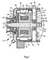
- FIG. 1is a cross-sectional view of a first preferred embodiment of the present invention
- FIG. 2is a cross-sectional view of a second preferred embodiment of the present invention.
- FIG. 3is sectional view of the alternator of FIG. 2 taken along line 3 — 3 ;
- FIG. 4is sectional view of the alternator of FIG. 2 taken along line 4 — 4 ;
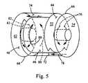
- FIG. 5is a schematic view illustrating the coolant flow through the alternator.
- an alternator of the present inventionis shown generally at 10 .
- the alternator 10includes an inner housing 12 which is adapted to support internal components of the alternator 10 .
- a rotor shaft 14is rotatably supported within the inner housing 12 by a pair of bearing elements 16 and 18 .
- a pulley 20is mounted to a first end of the shaft 14 and is adapted to engage a drive belt (not shown) to provide rotating drive to the shaft 14 of the alternator 10 .
- a pair of slip rings 22 and 24are mounted to a second end of the shaft 14 and are adapted to engage brushes 26 within the alternator 10 .
- a rotor assembly 28is mounted within the inner housing 12 .
- the rotor assembly 28includes first and second pole pieces 30 and 32 mounted onto the shaft 14 .
- An excitation winding 34is mounted between the first and second pole pieces 30 and 32 .
- a stator assembly 36is fixedly mounted within the inner housing 12 in functional engagement with the rotor assembly 28 .
- An outer housing 38is mounted over the inner housing 12 and an o-ring 40 is positioned between the inner housing 12 and the outer housing 38 , thereby creating a sealed flow chamber 42 .
- the flow chamber 42includes a first plenum 44 , an axial jacket 46 and a second plenum 48 .
- the axial jacket 46is positioned between and interconnects the first and second plenums 44 , 48 allowing fluid communication therebetween.
- the first plenum 44is a disk shaped cavity extending diametrically across the alternator 10 adjacent a rear end 50 of the alternator 10 .
- the first plenum 44is defined by a first disk shaped portion 52 of the inner housing 12 positioned at a distance from a second disk shaped portion 54 of the inner housing 12 and an inner diameter 56 of the outer housing 38 .
- the axial jacket 46extends annularly around the entire periphery of the alternator 10 and is defined by the cylindrical inner diameter 56 of the outer housing 38 , and a cylindrical outer diameter 58 of the inner housing 12 .
- the axial jacket 46forms an annular jacket which extends 360 degrees around the alternator 10 .
- the second plenum 48is a disk shaped cavity extending diametrically across the alternator 10 adjacent a front end 60 of the alternator 10 .
- the second plenum 48is defined by a third disk shaped portion 62 of the inner housing 12 positioned at a distance from a disk shaped front portion 64 of the outer housing 38 .
- An inlet 66extends from the first plenum 44 and is adapted to connect to a source of coolant and to allow coolant to enter the first plenum 44 .
- An outlet 68extends from the second plenum 48 and is adapted to allow coolant to exit the flow chamber 42 .
- the inlet 66 and the outlet 68are adapted to connect to the coolant system of an automobile.
- the design of the present inventionallows the alternator 10 to be compact enough to be placed upstream of a heater core so that the heat absorbed by the coolant flowing through the alternator 10 is then used in the heater core to provide warm air to the interior of the vehicle. Additionally, the design of the present invention allows the inlet 66 and the outlet 68 to be switched. The cooling of the alternator 10 is equally effective when the flow of coolant is reversed.
- a second preferred embodiment of the alternator of the present inventionis shown generally at 70 .
- Elements that are the same as those shown in the first preferred embodiment of FIG. 1are designated by the same reference numbers.
- the alternator 70 of the second preferred embodimentincludes a first passageway 72 positioned between the first plenum 44 and the axial jacket 46 and a second passageway 74 positioned between the axial jacket 46 and the third plenum 48 .
- the first and second passageways 72 , 74direct the coolant flow through the alternator 70 for more efficient cooling of the alternator 70 .
- the first passageway 72is defined by an arcuate notch formed within the first disk shaped portion 52 of the inner housing 12 .
- the first passageway 72is located diametrically across from the inlet 66 such that coolant flowing into the first plenum 44 from the inlet 66 must flow diametrically across the alternator 70 to reach the first passageway 72 . After flowing across the alternator 70 , the coolant will then change direction, flowing axially through the first passageway 72 into the axial jacket 46 .
- the second passageway 74is defined by an arcuate notch formed within the third disk shaped portion 62 of the inner housing 12 .
- the second passageway 74is located diametrically across from the first passageway 72 such that coolant flowing into the axial jacket 46 through the first passageway 72 must flow annularly around the alternator 70 to reach the second passageway 74 .
- the coolant flowing into the axial jacket 46splits evenly and flows tangentially back toward the second passageway 74 on the opposite side around both sides of the alternator 70 . After flowing around the alternator 70 , the coolant will then change direction, flowing axially through the second passageway 74 and into the second plenum 48 .
- the outlet 68is preferably located diametrically across from the second passageway such that coolant entering the second plenum 48 must flow diametrically across the alternator 70 to reach the outlet 68 .
- a schematic view of the alternator 70shows how the coolant flows therethrough.
- the coolantenters the first plenum 44 through the inlet 68 and flows diametrically across the alternator 70 as shown by arrows 76 .
- the coolantthen changes direction and flows axially through the first passageway 72 into the axial jacket 46 as shown by arrow 78 .
- the coolantflows annularly around the alternator 70 as shown by arrows 80 .
- the coolantthen changes direction and flows axially through the second passageway 74 into the second plenum 48 as shown by arrows 82 . Finally, the coolant flows diametrically across the alternator 70 through the second plenum 48 as shown by arrows 84 and exits through the outlet 68 .
Landscapes
- Engineering & Computer Science (AREA)
- Power Engineering (AREA)
- Motor Or Generator Cooling System (AREA)
- Motor Or Generator Frames (AREA)
Abstract
Description
Claims (8)
Priority Applications (4)
| Application Number | Priority Date | Filing Date | Title |
|---|---|---|---|
| US10/087,540US6674188B2 (en) | 2002-03-01 | 2002-03-01 | Liquid cooled alternator |
| GB0304191AGB2391398B (en) | 2002-03-01 | 2003-02-25 | Liquid cooled alternator |
| FR0302421AFR2836761B1 (en) | 2002-03-01 | 2003-02-27 | LIQUID COOLED ALTERNATOR |
| DE10308822ADE10308822A1 (en) | 2002-03-01 | 2003-02-27 | Liquid cooled generator |
Applications Claiming Priority (1)
| Application Number | Priority Date | Filing Date | Title |
|---|---|---|---|
| US10/087,540US6674188B2 (en) | 2002-03-01 | 2002-03-01 | Liquid cooled alternator |
Publications (2)
| Publication Number | Publication Date |
|---|---|
| US20030164650A1 US20030164650A1 (en) | 2003-09-04 |
| US6674188B2true US6674188B2 (en) | 2004-01-06 |
Family
ID=22205782
Family Applications (1)
| Application Number | Title | Priority Date | Filing Date |
|---|---|---|---|
| US10/087,540Expired - Fee RelatedUS6674188B2 (en) | 2002-03-01 | 2002-03-01 | Liquid cooled alternator |
Country Status (4)
| Country | Link |
|---|---|
| US (1) | US6674188B2 (en) |
| DE (1) | DE10308822A1 (en) |
| FR (1) | FR2836761B1 (en) |
| GB (1) | GB2391398B (en) |
Cited By (6)
| Publication number | Priority date | Publication date | Assignee | Title |
|---|---|---|---|---|
| US20070001534A1 (en)* | 2005-06-30 | 2007-01-04 | Fujitsu General Limited | Electric motor |
| US20080030084A1 (en)* | 2006-08-04 | 2008-02-07 | Denso Corporation | Cooling air flow passage for vehicular alternator |
| US20110304228A1 (en)* | 2010-06-14 | 2011-12-15 | Bradfield Michael D | Potted End Turns of an Electric Machine |
| US20140265659A1 (en)* | 2013-03-14 | 2014-09-18 | Remy Technologies, Llc | L-shaped sheet metal cooling jacket with stamped bearing support |
| US10427709B2 (en)* | 2016-02-05 | 2019-10-01 | Denso Corporation | Electric motor and electric power steering apparatus having the same |
| US12341400B2 (en) | 2022-03-24 | 2025-06-24 | C.E. Niehoff & Co. | Manifold assembly for a fluid cooled generator |
Families Citing this family (7)
| Publication number | Priority date | Publication date | Assignee | Title |
|---|---|---|---|---|
| US20040090133A1 (en)* | 2002-11-13 | 2004-05-13 | Yockey Steven John | Alternator assembly |
| SE534838C2 (en)* | 2010-05-21 | 2012-01-17 | Bae Systems Haegglunds Ab | Electric motor cooling device |
| FR3051995A1 (en)* | 2016-05-27 | 2017-12-01 | Valeo Systemes De Controle Moteur | ELECTRICAL COMPRESSOR WITH THREE-PART COOLING CIRCUIT |
| DE112018007338T5 (en)* | 2018-03-23 | 2020-12-10 | Mitsubishi Electric Corporation | Electric lathe with brush |
| WO2019235537A1 (en)* | 2018-06-08 | 2019-12-12 | アイシン・エィ・ダブリュ株式会社 | Dynamo-electric machine, and drive device for vehicle comprising dynamo-electric machine |
| US10888036B1 (en)* | 2019-12-18 | 2021-01-05 | Toyota Motor Engineering & Manufacturing North America, Inc. | Thermal management assemblies for electronic assemblies circumferentially mounted on a motor |
| CN114389398A (en)* | 2022-01-19 | 2022-04-22 | 湖南中车尚驱电气有限公司 | Diffusion end cover and motor |
Citations (79)
| Publication number | Priority date | Publication date | Assignee | Title |
|---|---|---|---|---|
| US2294586A (en) | 1941-08-04 | 1942-09-01 | Del Conveyor & Mfg Company | Axial flow fan structure |
| US2479223A (en) | 1947-10-28 | 1949-08-16 | Gerald T Evans | Nonmetallic sheath cable connector |
| JPS5446306A (en) | 1977-09-20 | 1979-04-12 | Nippon Denso Co Ltd | Cooling system for electric rotary machine |
| JPS5566249A (en) | 1978-11-13 | 1980-05-19 | Nippon Denso Co Ltd | Alternating current generator for car |
| JPS561749A (en) | 1979-06-15 | 1981-01-09 | Toshiba Corp | Salient-pole type electric rotary machine |
| US4262224A (en) | 1978-06-29 | 1981-04-14 | Robert Bosch Gmbh | Oil cooling for an electrical generator |
| JPS5653555A (en) | 1979-10-09 | 1981-05-13 | Nippon Denso Co Ltd | Ac generator for car |
| JPS5686052A (en) | 1979-12-14 | 1981-07-13 | Nippon Denso Co Ltd | Alternating current generator for vehicle |
| JPS576551A (en) | 1980-06-12 | 1982-01-13 | Nippon Denso Co Ltd | Ac generator for vehicle |
| US4418295A (en) | 1979-10-09 | 1983-11-29 | Nippondenso Co., Ltd. | Multi-path cooling in AC generator for vehicle |
| US4464594A (en) | 1982-04-28 | 1984-08-07 | Mitsubishi Denki Kabushiki Kaisha | Vehicular generator with cooling fan made of rubber covered shape memorizing alloy |
| US4488070A (en) | 1982-11-30 | 1984-12-11 | Mitsubishi Denki Kabushiki Kaisha | Alternating current generator for a car having a multi part partition plate for aiding a cooling fan |
| US4617485A (en) | 1983-12-19 | 1986-10-14 | Nippondenso Co., Ltd. | Rotor of alternator mounted on vehicle |
| US4659950A (en) | 1985-01-12 | 1987-04-21 | Mitsubishi Denki Kabushiki Kaisha | Charging generator for a vehicle |
| JPS62160055A (en) | 1986-01-08 | 1987-07-16 | Hitachi Ltd | Cooling ventilation mechanism for vehicle alternator |
| US4686399A (en) | 1983-10-25 | 1987-08-11 | Mitsubishi Denki Kabushiki Kaisha | Rotor for rotary electrical machines |
| JPS6377357A (en) | 1986-09-19 | 1988-04-07 | Hitachi Ltd | Inductor type ac generator |
| US4739204A (en) | 1986-01-30 | 1988-04-19 | Mitsubishi Denki Kabushiki Kaisha | Liquid cooled a.c. vehicle generator |
| US4757221A (en) | 1986-03-20 | 1988-07-12 | Hitachi, Ltd. | Alternator for automobile |
| JPS63181637A (en) | 1987-01-23 | 1988-07-26 | Nippon Denso Co Ltd | Ac generator for vehicle |
| JPS63265545A (en) | 1987-04-22 | 1988-11-02 | Hitachi Ltd | Vehicle alternator |
| JPS63274342A (en) | 1987-04-28 | 1988-11-11 | Honda Motor Co Ltd | Alternator cooling system |
| US4818906A (en) | 1986-04-07 | 1989-04-04 | Mitsubishi Denki Kabushiki Kaisha | Vehicle mounted A.C. generator |
| US4870307A (en)* | 1987-04-13 | 1989-09-26 | Mitsubishi Denki Kabushiki Kaisha | Block-mounted water cooled ac generator |
| US4994700A (en)* | 1990-02-15 | 1991-02-19 | Sundstrand Corporation | Dynamoelectric machine oil-cooled stator winding |
| US5021696A (en) | 1989-09-14 | 1991-06-04 | Ford Motor Company | Cooling fan with reduced noise for variable speed machinery |
| US5028826A (en) | 1989-06-02 | 1991-07-02 | Mitsubishi Denki K.K. | Fan arrangement for a vehicular AC generator |
| JPH03235644A (en) | 1990-02-07 | 1991-10-21 | Hitachi Ltd | Vehicle alternator |
| JPH03265450A (en) | 1990-03-13 | 1991-11-26 | Nippondenso Co Ltd | Rotor for automotive ac generator |
| US5093591A (en) | 1989-02-15 | 1992-03-03 | Mitsubishi Denki Kabushiki Kaisha | Alternating current generator with vented fan-like pulleys |
| US5095235A (en) | 1989-12-04 | 1992-03-10 | Mitsubishi Denki K.K. | Vehicle ac generator |
| JPH04244770A (en) | 1991-01-31 | 1992-09-01 | Nippondenso Co Ltd | Ac generator for vehicle |
| US5149997A (en) | 1989-07-14 | 1992-09-22 | Abb Stromberg Drives Oy | Fan for an electrically operated machine |
| US5194770A (en) | 1990-09-28 | 1993-03-16 | Mitsubishi Denki K.K. | Vehicular a.c. generator |
| EP0539339A1 (en) | 1991-10-23 | 1993-04-28 | INDUSTRIE MAGNETI MARELLI S.p.A. | Rotating electric machine, particularly an alternator for motor vehicles |
| JPH05111222A (en) | 1991-10-15 | 1993-04-30 | Mitsubishi Electric Corp | Ac generator for vehicle |
| JPH05111221A (en) | 1991-10-15 | 1993-04-30 | Mitsubishi Electric Corp | Vehicle alternator |
| JPH05137297A (en) | 1991-11-12 | 1993-06-01 | Mitsubishi Electric Corp | Vehicle alternator |
| US5233255A (en) | 1991-07-19 | 1993-08-03 | Mitsubishi Denki K.K. | AC generator for vehicles |
| JPH05219685A (en) | 1992-02-04 | 1993-08-27 | Hitachi Ltd | Vehicle AC generator cooling system |
| US5241230A (en) | 1991-10-15 | 1993-08-31 | Mitsubishi Denki K.K. | Cooling fan with reduced noise capability in an ac generator |
| JPH05236701A (en) | 1991-12-24 | 1993-09-10 | Mitsubishi Electric Corp | Fan for ventilating and cooling ac generator of vehicle and manufacture thereof |
| US5250864A (en) | 1991-07-19 | 1993-10-05 | Mitsubishi Denki K.K. | AC generator for vehicles |
| US5250863A (en)* | 1991-09-03 | 1993-10-05 | Itt Flygt Ab | Motor and cooling means therefor |
| JPH05268749A (en) | 1992-03-18 | 1993-10-15 | Mitsubishi Electric Corp | Vehicle alternator |
| JPH05336704A (en) | 1992-05-29 | 1993-12-17 | Mitsubishi Electric Corp | Vehicle alternator |
| US5293089A (en) | 1989-12-15 | 1994-03-08 | Robert Bosch Gmbh | Liquid-cooled electric generator |
| JPH0678504A (en) | 1992-08-25 | 1994-03-18 | Hitachi Ltd | Ac generator for vehicle |
| JPH0678479A (en) | 1992-07-07 | 1994-03-18 | Nippondenso Co Ltd | Rotor of ac generator for vehicle |
| JPH0698511A (en) | 1992-09-11 | 1994-04-08 | Hitachi Ltd | Vehicle alternator |
| JPH06113505A (en) | 1992-09-28 | 1994-04-22 | Nippondenso Co Ltd | Ac generator for vehicle |
| US5306977A (en) | 1991-08-08 | 1994-04-26 | Nippondenso Co., Ltd. | Cooling rotor for an alternator mounted on vehicle |
| US5317224A (en)* | 1990-02-03 | 1994-05-31 | Robert Bosch Gmbh | Electric machine with means for guiding cooling air supplied from outside of the machine |
| US5345132A (en) | 1992-06-23 | 1994-09-06 | Hitachi Automotive Engineering | Vehicular alternating current dynamo |
| US5424600A (en) | 1991-11-06 | 1995-06-13 | Nippondenso Co., Ltd. | Spark protected alternator |
| US5561334A (en) | 1993-07-26 | 1996-10-01 | Nippondenso Co., Ltd. | Rotary electric machine with increased cooling capacity |
| US5670838A (en)* | 1991-06-05 | 1997-09-23 | Unique Mobility, Inc. | Electrical machines |
| US5710467A (en) | 1993-07-26 | 1998-01-20 | Nippondenso Co., Ltd. | Alternator |
| US5742107A (en) | 1993-12-28 | 1998-04-21 | Mitsubishi Denki Kabushiki Kaisha | Rotary cooling fan |
| US5751079A (en) | 1996-10-17 | 1998-05-12 | Ford Motor Company | Alternator with internal and external fans |
| US5763968A (en) | 1996-04-22 | 1998-06-09 | Denso Corporation | Alternator for vehicle |
| US5777407A (en) | 1994-03-11 | 1998-07-07 | Nippondenso Co., Ltd. | Alternator for vehicle |
| USD401319S (en) | 1997-05-05 | 1998-11-17 | Fanco, Inc. | Alternator fan |
| US5952749A (en) | 1997-05-26 | 1999-09-14 | Denso Corporation | Cooling arrangement of alternator |
| US5977668A (en) | 1998-09-07 | 1999-11-02 | Mitsubishi Denki Kabushiki Kaisha | Vehicle alternator and method of manufacture therefor |
| US5977669A (en) | 1995-11-08 | 1999-11-02 | Denso Corporation | Fastening means for contacting DC-output terminal with cooling fin in AC generator |
| US6018205A (en) | 1998-07-21 | 2000-01-25 | Mitsubishi Denki Kabushiki Kaisha | Vehicle alternator |
| US6023112A (en) | 1995-11-06 | 2000-02-08 | Mitsubishi Denki Kabushiki Kaisha | Alternating current generator with improved fan system |
| US6057627A (en) | 1996-08-09 | 2000-05-02 | Robert Bosch Gmbh | Claw pole generator with ventilation fan supporting the magnetic pole tips |
| US6060802A (en) | 1997-09-25 | 2000-05-09 | Denso Corporation | AC generator for an automotive vehicle |
| US6124660A (en) | 1997-05-26 | 2000-09-26 | Denso Corporation | AC generator for vehicles |
| US6198188B1 (en) | 1999-03-03 | 2001-03-06 | Denso Corporation | Rectifier cooling fin arrangement of vehicle AC generator |
| US6198187B1 (en) | 1999-05-26 | 2001-03-06 | Mitsubishi Denki Kabushiki Kaisha | Automotive alternator |
| US20010010434A1 (en) | 2000-01-31 | 2001-08-02 | Hitachi, Ltd. | Vehicle AC generator |
| US6285100B1 (en) | 1997-02-12 | 2001-09-04 | Robert Bosch Gmbh | Electrical machine, preferably a rotary current generator with a rectifier component and with upper heat sink provided with axial cooling fins |
| US20010026102A1 (en) | 2000-03-30 | 2001-10-04 | Yoshihito Asao | Automotive alternator |
| JP3235644B2 (en) | 1996-12-11 | 2001-12-04 | 東京都 | Sludge incinerator start-up operation control method and apparatus |
| US20010054852A1 (en) | 2000-06-21 | 2001-12-27 | Denso Corporation | Cooling arrangement of vehicle rotary electric machine |
| JP3265450B2 (en) | 1996-03-06 | 2002-03-11 | シャープ株式会社 | Air conditioner and indoor unit for air conditioner |
Family Cites Families (5)
| Publication number | Priority date | Publication date | Assignee | Title |
|---|---|---|---|---|
| EP0816147A3 (en)* | 1996-07-02 | 2000-03-08 | Denso Corporation | Rotating apparatus and heating apparatus, for vehicle |
| DE19721527C1 (en)* | 1997-05-22 | 1998-11-05 | Still Gmbh | Unit consisting of an internal combustion engine, generator and pump unit |
| JP2000083351A (en)* | 1998-09-03 | 2000-03-21 | Hitachi Ltd | Vehicle alternator and vehicle cooling system |
| DE19854466C1 (en)* | 1998-11-25 | 2000-04-13 | Daimler Chrysler Ag | Fluid cooled electrical generator e.g. automobile alternator, has cooling ribs and channel walls projecting into gap for cooling fluid between generator and encapsulation housing |
| GB2357377A (en)* | 1999-12-13 | 2001-06-20 | Delphi Tech Inc | Cooling a combined pump and electric generator |
- 2002
- 2002-03-01USUS10/087,540patent/US6674188B2/ennot_activeExpired - Fee Related
- 2003
- 2003-02-25GBGB0304191Apatent/GB2391398B/ennot_activeExpired - Fee Related
- 2003-02-27DEDE10308822Apatent/DE10308822A1/ennot_activeWithdrawn
- 2003-02-27FRFR0302421Apatent/FR2836761B1/ennot_activeExpired - Fee Related
Patent Citations (84)
| Publication number | Priority date | Publication date | Assignee | Title |
|---|---|---|---|---|
| US2294586A (en) | 1941-08-04 | 1942-09-01 | Del Conveyor & Mfg Company | Axial flow fan structure |
| US2479223A (en) | 1947-10-28 | 1949-08-16 | Gerald T Evans | Nonmetallic sheath cable connector |
| JPS5446306A (en) | 1977-09-20 | 1979-04-12 | Nippon Denso Co Ltd | Cooling system for electric rotary machine |
| US4262224A (en) | 1978-06-29 | 1981-04-14 | Robert Bosch Gmbh | Oil cooling for an electrical generator |
| JPS5566249A (en) | 1978-11-13 | 1980-05-19 | Nippon Denso Co Ltd | Alternating current generator for car |
| JPS561749A (en) | 1979-06-15 | 1981-01-09 | Toshiba Corp | Salient-pole type electric rotary machine |
| JPS5653555A (en) | 1979-10-09 | 1981-05-13 | Nippon Denso Co Ltd | Ac generator for car |
| US4418295A (en) | 1979-10-09 | 1983-11-29 | Nippondenso Co., Ltd. | Multi-path cooling in AC generator for vehicle |
| JPS5686052A (en) | 1979-12-14 | 1981-07-13 | Nippon Denso Co Ltd | Alternating current generator for vehicle |
| US4794285A (en) | 1979-12-14 | 1988-12-27 | Nippondenso Co., Ltd. | Vehicle AC generator with voltage regulator |
| EP0300063B1 (en) | 1979-12-14 | 1992-03-04 | Nippondenso Co., Ltd. | An alternative current generator with a voltage regulator unit for use in vehicles |
| JPS576551A (en) | 1980-06-12 | 1982-01-13 | Nippon Denso Co Ltd | Ac generator for vehicle |
| US4464594A (en) | 1982-04-28 | 1984-08-07 | Mitsubishi Denki Kabushiki Kaisha | Vehicular generator with cooling fan made of rubber covered shape memorizing alloy |
| US4488070A (en) | 1982-11-30 | 1984-12-11 | Mitsubishi Denki Kabushiki Kaisha | Alternating current generator for a car having a multi part partition plate for aiding a cooling fan |
| US4686399A (en) | 1983-10-25 | 1987-08-11 | Mitsubishi Denki Kabushiki Kaisha | Rotor for rotary electrical machines |
| US4617485A (en) | 1983-12-19 | 1986-10-14 | Nippondenso Co., Ltd. | Rotor of alternator mounted on vehicle |
| US4659950A (en) | 1985-01-12 | 1987-04-21 | Mitsubishi Denki Kabushiki Kaisha | Charging generator for a vehicle |
| JPS62160055A (en) | 1986-01-08 | 1987-07-16 | Hitachi Ltd | Cooling ventilation mechanism for vehicle alternator |
| US4739204A (en) | 1986-01-30 | 1988-04-19 | Mitsubishi Denki Kabushiki Kaisha | Liquid cooled a.c. vehicle generator |
| US4757221A (en) | 1986-03-20 | 1988-07-12 | Hitachi, Ltd. | Alternator for automobile |
| US4818906A (en) | 1986-04-07 | 1989-04-04 | Mitsubishi Denki Kabushiki Kaisha | Vehicle mounted A.C. generator |
| JPS6377357A (en) | 1986-09-19 | 1988-04-07 | Hitachi Ltd | Inductor type ac generator |
| JPS63181637A (en) | 1987-01-23 | 1988-07-26 | Nippon Denso Co Ltd | Ac generator for vehicle |
| US4870307A (en)* | 1987-04-13 | 1989-09-26 | Mitsubishi Denki Kabushiki Kaisha | Block-mounted water cooled ac generator |
| JPS63265545A (en) | 1987-04-22 | 1988-11-02 | Hitachi Ltd | Vehicle alternator |
| JPS63274342A (en) | 1987-04-28 | 1988-11-11 | Honda Motor Co Ltd | Alternator cooling system |
| US5093591A (en) | 1989-02-15 | 1992-03-03 | Mitsubishi Denki Kabushiki Kaisha | Alternating current generator with vented fan-like pulleys |
| US5028826A (en) | 1989-06-02 | 1991-07-02 | Mitsubishi Denki K.K. | Fan arrangement for a vehicular AC generator |
| US5149997A (en) | 1989-07-14 | 1992-09-22 | Abb Stromberg Drives Oy | Fan for an electrically operated machine |
| US5021696A (en) | 1989-09-14 | 1991-06-04 | Ford Motor Company | Cooling fan with reduced noise for variable speed machinery |
| US5095235A (en) | 1989-12-04 | 1992-03-10 | Mitsubishi Denki K.K. | Vehicle ac generator |
| US5293089A (en) | 1989-12-15 | 1994-03-08 | Robert Bosch Gmbh | Liquid-cooled electric generator |
| US5317224A (en)* | 1990-02-03 | 1994-05-31 | Robert Bosch Gmbh | Electric machine with means for guiding cooling air supplied from outside of the machine |
| JPH03235644A (en) | 1990-02-07 | 1991-10-21 | Hitachi Ltd | Vehicle alternator |
| US4994700A (en)* | 1990-02-15 | 1991-02-19 | Sundstrand Corporation | Dynamoelectric machine oil-cooled stator winding |
| JPH03265450A (en) | 1990-03-13 | 1991-11-26 | Nippondenso Co Ltd | Rotor for automotive ac generator |
| US5194770A (en) | 1990-09-28 | 1993-03-16 | Mitsubishi Denki K.K. | Vehicular a.c. generator |
| JPH04244770A (en) | 1991-01-31 | 1992-09-01 | Nippondenso Co Ltd | Ac generator for vehicle |
| US5670838A (en)* | 1991-06-05 | 1997-09-23 | Unique Mobility, Inc. | Electrical machines |
| US5233255A (en) | 1991-07-19 | 1993-08-03 | Mitsubishi Denki K.K. | AC generator for vehicles |
| US5250864A (en) | 1991-07-19 | 1993-10-05 | Mitsubishi Denki K.K. | AC generator for vehicles |
| US5306977A (en) | 1991-08-08 | 1994-04-26 | Nippondenso Co., Ltd. | Cooling rotor for an alternator mounted on vehicle |
| US5250863A (en)* | 1991-09-03 | 1993-10-05 | Itt Flygt Ab | Motor and cooling means therefor |
| US5241230A (en) | 1991-10-15 | 1993-08-31 | Mitsubishi Denki K.K. | Cooling fan with reduced noise capability in an ac generator |
| US5235229A (en) | 1991-10-15 | 1993-08-10 | Mitsubishi Denki K.K. | Vehicular AC generator |
| JPH05111221A (en) | 1991-10-15 | 1993-04-30 | Mitsubishi Electric Corp | Vehicle alternator |
| JPH05111222A (en) | 1991-10-15 | 1993-04-30 | Mitsubishi Electric Corp | Ac generator for vehicle |
| EP0539339A1 (en) | 1991-10-23 | 1993-04-28 | INDUSTRIE MAGNETI MARELLI S.p.A. | Rotating electric machine, particularly an alternator for motor vehicles |
| US5424600A (en) | 1991-11-06 | 1995-06-13 | Nippondenso Co., Ltd. | Spark protected alternator |
| JPH05137297A (en) | 1991-11-12 | 1993-06-01 | Mitsubishi Electric Corp | Vehicle alternator |
| JPH05236701A (en) | 1991-12-24 | 1993-09-10 | Mitsubishi Electric Corp | Fan for ventilating and cooling ac generator of vehicle and manufacture thereof |
| JPH05219685A (en) | 1992-02-04 | 1993-08-27 | Hitachi Ltd | Vehicle AC generator cooling system |
| JPH05268749A (en) | 1992-03-18 | 1993-10-15 | Mitsubishi Electric Corp | Vehicle alternator |
| JPH05336704A (en) | 1992-05-29 | 1993-12-17 | Mitsubishi Electric Corp | Vehicle alternator |
| US5345132A (en) | 1992-06-23 | 1994-09-06 | Hitachi Automotive Engineering | Vehicular alternating current dynamo |
| JPH0678479A (en) | 1992-07-07 | 1994-03-18 | Nippondenso Co Ltd | Rotor of ac generator for vehicle |
| JPH0678504A (en) | 1992-08-25 | 1994-03-18 | Hitachi Ltd | Ac generator for vehicle |
| JPH0698511A (en) | 1992-09-11 | 1994-04-08 | Hitachi Ltd | Vehicle alternator |
| JPH06113505A (en) | 1992-09-28 | 1994-04-22 | Nippondenso Co Ltd | Ac generator for vehicle |
| US5561334A (en) | 1993-07-26 | 1996-10-01 | Nippondenso Co., Ltd. | Rotary electric machine with increased cooling capacity |
| US5705865A (en) | 1993-07-26 | 1998-01-06 | Nippondenso Co., Ltd. | Rotary electric machine with increased cooling capacity |
| US5710467A (en) | 1993-07-26 | 1998-01-20 | Nippondenso Co., Ltd. | Alternator |
| US5742107A (en) | 1993-12-28 | 1998-04-21 | Mitsubishi Denki Kabushiki Kaisha | Rotary cooling fan |
| US5777407A (en) | 1994-03-11 | 1998-07-07 | Nippondenso Co., Ltd. | Alternator for vehicle |
| US6172433B1 (en) | 1995-10-06 | 2001-01-09 | Mitsubishi Denki Kabushiki Kaisha | Alternating current generator with improved fans system |
| US6023112A (en) | 1995-11-06 | 2000-02-08 | Mitsubishi Denki Kabushiki Kaisha | Alternating current generator with improved fan system |
| US5977669A (en) | 1995-11-08 | 1999-11-02 | Denso Corporation | Fastening means for contacting DC-output terminal with cooling fin in AC generator |
| JP3265450B2 (en) | 1996-03-06 | 2002-03-11 | シャープ株式会社 | Air conditioner and indoor unit for air conditioner |
| US5763968A (en) | 1996-04-22 | 1998-06-09 | Denso Corporation | Alternator for vehicle |
| US6057627A (en) | 1996-08-09 | 2000-05-02 | Robert Bosch Gmbh | Claw pole generator with ventilation fan supporting the magnetic pole tips |
| US5751079A (en) | 1996-10-17 | 1998-05-12 | Ford Motor Company | Alternator with internal and external fans |
| JP3235644B2 (en) | 1996-12-11 | 2001-12-04 | 東京都 | Sludge incinerator start-up operation control method and apparatus |
| US6285100B1 (en) | 1997-02-12 | 2001-09-04 | Robert Bosch Gmbh | Electrical machine, preferably a rotary current generator with a rectifier component and with upper heat sink provided with axial cooling fins |
| USD401319S (en) | 1997-05-05 | 1998-11-17 | Fanco, Inc. | Alternator fan |
| US6124660A (en) | 1997-05-26 | 2000-09-26 | Denso Corporation | AC generator for vehicles |
| US5952749A (en) | 1997-05-26 | 1999-09-14 | Denso Corporation | Cooling arrangement of alternator |
| US6060802A (en) | 1997-09-25 | 2000-05-09 | Denso Corporation | AC generator for an automotive vehicle |
| US6018205A (en) | 1998-07-21 | 2000-01-25 | Mitsubishi Denki Kabushiki Kaisha | Vehicle alternator |
| US5977668A (en) | 1998-09-07 | 1999-11-02 | Mitsubishi Denki Kabushiki Kaisha | Vehicle alternator and method of manufacture therefor |
| US6198188B1 (en) | 1999-03-03 | 2001-03-06 | Denso Corporation | Rectifier cooling fin arrangement of vehicle AC generator |
| US6198187B1 (en) | 1999-05-26 | 2001-03-06 | Mitsubishi Denki Kabushiki Kaisha | Automotive alternator |
| US20010010434A1 (en) | 2000-01-31 | 2001-08-02 | Hitachi, Ltd. | Vehicle AC generator |
| US20010026102A1 (en) | 2000-03-30 | 2001-10-04 | Yoshihito Asao | Automotive alternator |
| US20010054852A1 (en) | 2000-06-21 | 2001-12-27 | Denso Corporation | Cooling arrangement of vehicle rotary electric machine |
Non-Patent Citations (9)
| Title |
|---|
| English translation of Abstract corresponding to European Patent No. 0 539 339. |
| English translation of Abstract corresponding to Japanese Patent No. 54-46306. |
| English translation of Abstract corresponding to Japanese Patent No. 55-66249. |
| English translation of Abstract corresponding to Japanese Patent No. 56-1749. |
| English translation of Abstract corresponding to Japanese Patent No. 56-53555. |
| English translation of Abstract corresponding to Japanese Patent No. 56-86052. |
| English translation of Abstract corresponding to Japanese Patent No. 57-6551. |
| English translation of Abstract corresponding to Japanese Patent No. 62-160055. |
| English translation of Abstract corresponding to Japanese Patent No. 77357. |
Cited By (9)
| Publication number | Priority date | Publication date | Assignee | Title |
|---|---|---|---|---|
| US20070001534A1 (en)* | 2005-06-30 | 2007-01-04 | Fujitsu General Limited | Electric motor |
| US7608954B2 (en)* | 2005-06-30 | 2009-10-27 | Fujitsu General Limited | Electric motor |
| US20080030084A1 (en)* | 2006-08-04 | 2008-02-07 | Denso Corporation | Cooling air flow passage for vehicular alternator |
| US20110304228A1 (en)* | 2010-06-14 | 2011-12-15 | Bradfield Michael D | Potted End Turns of an Electric Machine |
| US8552600B2 (en)* | 2010-06-14 | 2013-10-08 | Remy Technologies, Llc | Potted end turns of an electric machine |
| US20140265659A1 (en)* | 2013-03-14 | 2014-09-18 | Remy Technologies, Llc | L-shaped sheet metal cooling jacket with stamped bearing support |
| US9130421B2 (en)* | 2013-03-14 | 2015-09-08 | Remy Technologies, Llc | L-shaped sheet metal cooling jacket with stamped bearing support |
| US10427709B2 (en)* | 2016-02-05 | 2019-10-01 | Denso Corporation | Electric motor and electric power steering apparatus having the same |
| US12341400B2 (en) | 2022-03-24 | 2025-06-24 | C.E. Niehoff & Co. | Manifold assembly for a fluid cooled generator |
Also Published As
| Publication number | Publication date |
|---|---|
| GB2391398A (en) | 2004-02-04 |
| FR2836761A1 (en) | 2003-09-05 |
| GB2391398B (en) | 2004-09-01 |
| US20030164650A1 (en) | 2003-09-04 |
| FR2836761B1 (en) | 2004-11-19 |
| DE10308822A1 (en) | 2003-10-09 |
| GB0304191D0 (en) | 2003-03-26 |
Similar Documents
| Publication | Publication Date | Title |
|---|---|---|
| US6617715B1 (en) | Liquid cooled alternator having finned stator sleeve | |
| US6674188B2 (en) | Liquid cooled alternator | |
| US6617716B2 (en) | Rotary electric machine having stator coolant passage means | |
| EP1722463B1 (en) | Rotary electric machine for vehicles | |
| US6680552B2 (en) | Flow path for a liquid cooled alternator | |
| US7545060B2 (en) | Method and apparatus for heat removal from electric motor winding end-turns | |
| US6909210B1 (en) | Cooling system for dynamoelectric machine | |
| JP2859437B2 (en) | Externally ventilated electrical machines | |
| US20090121562A1 (en) | Device and method for cooling motor for hybrid electric vehicles | |
| JPS62221839A (en) | Ac generator for motor car | |
| US6747384B2 (en) | Alternator hybrid magnet rotor design | |
| US6777845B2 (en) | High output alternator bobbin | |
| US8933599B2 (en) | Cooling system of electric rotating machine for vehicles | |
| CN114649890A (en) | Electric machine for driving a motor vehicle | |
| US20160056690A1 (en) | Rotating electric machine | |
| US20100270874A1 (en) | Arrangement for a power electronics unit in a hybrid vehicle | |
| CN114649884A (en) | Electric machine for driving a motor vehicle | |
| EP3046792B1 (en) | An electric or hybrid vehicle using motor-generator having shaft with centrifugal fan blades for cooling | |
| US6933635B2 (en) | Automotive alternator | |
| CN215009876U (en) | Permanent magnet motor driving device with forced air cooling structure | |
| JP3707476B2 (en) | Vehicle alternator | |
| US20240001807A1 (en) | Energy dissipation system | |
| KR20090042386A (en) | Integrated motor unit for hybrid vehicles using two-speed magnetic clutch | |
| KR101172675B1 (en) | Driving motor cooling device for hybrid electric vehicle | |
| US6724116B1 (en) | Alternator permanent magnet rotor design |
Legal Events
| Date | Code | Title | Description |
|---|---|---|---|
| AS | Assignment | Owner name:VISTEON GLOBAL TECHNOLOGIES, INC., MICHIGAN Free format text:ASSIGNMENT OF ASSIGNORS INTEREST;ASSIGNORS:YOCKEY, STEVEN J.;HARPENAU, KEVIN ROY;LINDEN, DAVID WILLIAM;AND OTHERS;REEL/FRAME:012943/0433 Effective date:20020220 | |
| FPAY | Fee payment | Year of fee payment:4 | |
| AS | Assignment | Owner name:JPMORGAN CHASE BANK, N.A., AS ADMINISTRATIVE AGENT Free format text:SECURITY AGREEMENT;ASSIGNOR:VISTEON GLOBAL TECHNOLOGIES, INC.;REEL/FRAME:020497/0733 Effective date:20060613 | |
| AS | Assignment | Owner name:JPMORGAN CHASE BANK, TEXAS Free format text:SECURITY INTEREST;ASSIGNOR:VISTEON GLOBAL TECHNOLOGIES, INC.;REEL/FRAME:022368/0001 Effective date:20060814 Owner name:JPMORGAN CHASE BANK,TEXAS Free format text:SECURITY INTEREST;ASSIGNOR:VISTEON GLOBAL TECHNOLOGIES, INC.;REEL/FRAME:022368/0001 Effective date:20060814 | |
| AS | Assignment | Owner name:WILMINGTON TRUST FSB, AS ADMINISTRATIVE AGENT, MIN Free format text:ASSIGNMENT OF SECURITY INTEREST IN PATENTS;ASSIGNOR:JPMORGAN CHASE BANK, N.A., AS ADMINISTRATIVE AGENT;REEL/FRAME:022575/0186 Effective date:20090415 Owner name:WILMINGTON TRUST FSB, AS ADMINISTRATIVE AGENT,MINN Free format text:ASSIGNMENT OF SECURITY INTEREST IN PATENTS;ASSIGNOR:JPMORGAN CHASE BANK, N.A., AS ADMINISTRATIVE AGENT;REEL/FRAME:022575/0186 Effective date:20090415 | |
| AS | Assignment | Owner name:THE BANK OF NEW YORK MELLON, AS ADMINISTRATIVE AGE Free format text:ASSIGNMENT OF PATENT SECURITY INTEREST;ASSIGNOR:JPMORGAN CHASE BANK, N.A., A NATIONAL BANKING ASSOCIATION;REEL/FRAME:022974/0057 Effective date:20090715 | |
| AS | Assignment | Owner name:VISTEON GLOBAL TECHNOLOGIES, INC., MICHIGAN Free format text:RELEASE BY SECURED PARTY AGAINST SECURITY INTEREST IN PATENTS RECORDED AT REEL 022974 FRAME 0057;ASSIGNOR:THE BANK OF NEW YORK MELLON;REEL/FRAME:025095/0711 Effective date:20101001 | |
| AS | Assignment | Owner name:VISTEON GLOBAL TECHNOLOGIES, INC., MICHIGAN Free format text:RELEASE BY SECURED PARTY AGAINST SECURITY INTEREST IN PATENTS RECORDED AT REEL 022575 FRAME 0186;ASSIGNOR:WILMINGTON TRUST FSB, AS ADMINISTRATIVE AGENT;REEL/FRAME:025105/0201 Effective date:20101001 | |
| AS | Assignment | Owner name:MORGAN STANLEY SENIOR FUNDING, INC., AS AGENT, NEW Free format text:SECURITY AGREEMENT (REVOLVER);ASSIGNORS:VISTEON CORPORATION;VC AVIATION SERVICES, LLC;VISTEON ELECTRONICS CORPORATION;AND OTHERS;REEL/FRAME:025238/0298 Effective date:20101001 Owner name:MORGAN STANLEY SENIOR FUNDING, INC., AS AGENT, NEW Free format text:SECURITY AGREEMENT;ASSIGNORS:VISTEON CORPORATION;VC AVIATION SERVICES, LLC;VISTEON ELECTRONICS CORPORATION;AND OTHERS;REEL/FRAME:025241/0317 Effective date:20101007 | |
| AS | Assignment | Owner name:VISTEON GLOBAL TREASURY, INC., MICHIGAN Free format text:RELEASE BY SECURED PARTY AGAINST SECURITY INTEREST IN PATENTS ON REEL 025241 FRAME 0317;ASSIGNOR:MORGAN STANLEY SENIOR FUNDING, INC.;REEL/FRAME:026178/0412 Effective date:20110406 Owner name:VISTEON ELECTRONICS CORPORATION, MICHIGAN Free format text:RELEASE BY SECURED PARTY AGAINST SECURITY INTEREST IN PATENTS ON REEL 025241 FRAME 0317;ASSIGNOR:MORGAN STANLEY SENIOR FUNDING, INC.;REEL/FRAME:026178/0412 Effective date:20110406 Owner name:VISTEON SYSTEMS, LLC, MICHIGAN Free format text:RELEASE BY SECURED PARTY AGAINST SECURITY INTEREST IN PATENTS ON REEL 025241 FRAME 0317;ASSIGNOR:MORGAN STANLEY SENIOR FUNDING, INC.;REEL/FRAME:026178/0412 Effective date:20110406 Owner name:VC AVIATION SERVICES, LLC, MICHIGAN Free format text:RELEASE BY SECURED PARTY AGAINST SECURITY INTEREST IN PATENTS ON REEL 025241 FRAME 0317;ASSIGNOR:MORGAN STANLEY SENIOR FUNDING, INC.;REEL/FRAME:026178/0412 Effective date:20110406 Owner name:VISTEON INTERNATIONAL BUSINESS DEVELOPMENT, INC., Free format text:RELEASE BY SECURED PARTY AGAINST SECURITY INTEREST IN PATENTS ON REEL 025241 FRAME 0317;ASSIGNOR:MORGAN STANLEY SENIOR FUNDING, INC.;REEL/FRAME:026178/0412 Effective date:20110406 Owner name:VISTEON CORPORATION, MICHIGAN Free format text:RELEASE BY SECURED PARTY AGAINST SECURITY INTEREST IN PATENTS ON REEL 025241 FRAME 0317;ASSIGNOR:MORGAN STANLEY SENIOR FUNDING, INC.;REEL/FRAME:026178/0412 Effective date:20110406 Owner name:VISTEON INTERNATIONAL HOLDINGS, INC., MICHIGAN Free format text:RELEASE BY SECURED PARTY AGAINST SECURITY INTEREST IN PATENTS ON REEL 025241 FRAME 0317;ASSIGNOR:MORGAN STANLEY SENIOR FUNDING, INC.;REEL/FRAME:026178/0412 Effective date:20110406 Owner name:VISTEON GLOBAL TECHNOLOGIES, INC., MICHIGAN Free format text:RELEASE BY SECURED PARTY AGAINST SECURITY INTEREST IN PATENTS ON REEL 025241 FRAME 0317;ASSIGNOR:MORGAN STANLEY SENIOR FUNDING, INC.;REEL/FRAME:026178/0412 Effective date:20110406 Owner name:VISTEON EUROPEAN HOLDING, INC., MICHIGAN Free format text:RELEASE BY SECURED PARTY AGAINST SECURITY INTEREST IN PATENTS ON REEL 025241 FRAME 0317;ASSIGNOR:MORGAN STANLEY SENIOR FUNDING, INC.;REEL/FRAME:026178/0412 Effective date:20110406 | |
| REMI | Maintenance fee reminder mailed | ||
| LAPS | Lapse for failure to pay maintenance fees | ||
| STCH | Information on status: patent discontinuation | Free format text:PATENT EXPIRED DUE TO NONPAYMENT OF MAINTENANCE FEES UNDER 37 CFR 1.362 | |
| AS | Assignment | Owner name:VISTEON GLOBAL TECHNOLOGIES, INC., MICHIGAN Free format text:RELEASE OF SECURITY INTEREST IN INTELLECTUAL PROPERTY;ASSIGNOR:MORGAN STANLEY SENIOR FUNDING, INC.;REEL/FRAME:033107/0717 Effective date:20140409 Owner name:VISTEON SYSTEMS, LLC, MICHIGAN Free format text:RELEASE OF SECURITY INTEREST IN INTELLECTUAL PROPERTY;ASSIGNOR:MORGAN STANLEY SENIOR FUNDING, INC.;REEL/FRAME:033107/0717 Effective date:20140409 Owner name:VISTEON EUROPEAN HOLDINGS, INC., MICHIGAN Free format text:RELEASE OF SECURITY INTEREST IN INTELLECTUAL PROPERTY;ASSIGNOR:MORGAN STANLEY SENIOR FUNDING, INC.;REEL/FRAME:033107/0717 Effective date:20140409 Owner name:VISTEON CORPORATION, MICHIGAN Free format text:RELEASE OF SECURITY INTEREST IN INTELLECTUAL PROPERTY;ASSIGNOR:MORGAN STANLEY SENIOR FUNDING, INC.;REEL/FRAME:033107/0717 Effective date:20140409 Owner name:VISTEON INTERNATIONAL BUSINESS DEVELOPMENT, INC., Free format text:RELEASE OF SECURITY INTEREST IN INTELLECTUAL PROPERTY;ASSIGNOR:MORGAN STANLEY SENIOR FUNDING, INC.;REEL/FRAME:033107/0717 Effective date:20140409 Owner name:VC AVIATION SERVICES, LLC, MICHIGAN Free format text:RELEASE OF SECURITY INTEREST IN INTELLECTUAL PROPERTY;ASSIGNOR:MORGAN STANLEY SENIOR FUNDING, INC.;REEL/FRAME:033107/0717 Effective date:20140409 Owner name:VISTEON ELECTRONICS CORPORATION, MICHIGAN Free format text:RELEASE OF SECURITY INTEREST IN INTELLECTUAL PROPERTY;ASSIGNOR:MORGAN STANLEY SENIOR FUNDING, INC.;REEL/FRAME:033107/0717 Effective date:20140409 Owner name:VISTEON GLOBAL TREASURY, INC., MICHIGAN Free format text:RELEASE OF SECURITY INTEREST IN INTELLECTUAL PROPERTY;ASSIGNOR:MORGAN STANLEY SENIOR FUNDING, INC.;REEL/FRAME:033107/0717 Effective date:20140409 Owner name:VISTEON INTERNATIONAL HOLDINGS, INC., MICHIGAN Free format text:RELEASE OF SECURITY INTEREST IN INTELLECTUAL PROPERTY;ASSIGNOR:MORGAN STANLEY SENIOR FUNDING, INC.;REEL/FRAME:033107/0717 Effective date:20140409 |