US6673074B2 - Apparatus for retaining bone portions in a desired spatial relationship - Google Patents
Apparatus for retaining bone portions in a desired spatial relationshipDownload PDFInfo
- Publication number
- US6673074B2 US6673074B2US09/921,326US92132601AUS6673074B2US 6673074 B2US6673074 B2US 6673074B2US 92132601 AUS92132601 AUS 92132601AUS 6673074 B2US6673074 B2US 6673074B2
- Authority
- US
- United States
- Prior art keywords
- connecting ring
- fastener
- end portion
- longitudinal axis
- engageable
- Prior art date
- Legal status (The legal status is an assumption and is not a legal conclusion. Google has not performed a legal analysis and makes no representation as to the accuracy of the status listed.)
- Expired - Fee Related, expires
Links
- 210000000988bone and boneAnatomy0.000titleclaimsabstractdescription20
- 230000004048modificationEffects0.000description2
- 238000012986modificationMethods0.000description2
- 238000009434installationMethods0.000description1
Images

Classifications
- A—HUMAN NECESSITIES
- A61—MEDICAL OR VETERINARY SCIENCE; HYGIENE
- A61B—DIAGNOSIS; SURGERY; IDENTIFICATION
- A61B17/00—Surgical instruments, devices or methods
- A61B17/56—Surgical instruments or methods for treatment of bones or joints; Devices specially adapted therefor
- A61B17/58—Surgical instruments or methods for treatment of bones or joints; Devices specially adapted therefor for osteosynthesis, e.g. bone plates, screws or setting implements
- A61B17/68—Internal fixation devices, including fasteners and spinal fixators, even if a part thereof projects from the skin
- A61B17/70—Spinal positioners or stabilisers, e.g. stabilisers comprising fluid filler in an implant
- A61B17/7001—Screws or hooks combined with longitudinal elements which do not contact vertebrae
- A61B17/7035—Screws or hooks, wherein a rod-clamping part and a bone-anchoring part can pivot relative to each other
- A—HUMAN NECESSITIES
- A61—MEDICAL OR VETERINARY SCIENCE; HYGIENE
- A61B—DIAGNOSIS; SURGERY; IDENTIFICATION
- A61B17/00—Surgical instruments, devices or methods
- A61B17/56—Surgical instruments or methods for treatment of bones or joints; Devices specially adapted therefor
- A61B17/58—Surgical instruments or methods for treatment of bones or joints; Devices specially adapted therefor for osteosynthesis, e.g. bone plates, screws or setting implements
- A61B17/68—Internal fixation devices, including fasteners and spinal fixators, even if a part thereof projects from the skin
- A61B17/70—Spinal positioners or stabilisers, e.g. stabilisers comprising fluid filler in an implant
- A61B17/7001—Screws or hooks combined with longitudinal elements which do not contact vertebrae
- A61B17/7041—Screws or hooks combined with longitudinal elements which do not contact vertebrae with single longitudinal rod offset laterally from single row of screws or hooks
Definitions
- the present inventionrelates to an apparatus which is used to retain bone portions, such as vertebrae of a spinal column, in a desired spatial relationship.
- U.S. Pat. No. 5,613,968discloses an apparatus including a longitudinal member extendable along the spinal column.
- a fixation memberconnects the longitudinal member to a fastener connectable with a vertebra.
- a universal padconnects the fastener with the fixation member.
- the universal padextends into the fixation member and the fastener extends through the universal pad.
- the universal padhas a protruding arcuate surface and a recessed arcuate surface concentric with the protruding arcuate surface.
- a clamping memberis provided with a recessed arcuate surface engageable with the protruding arcuate surface on the universal pad.
- the fastenerhas a protruding arcuate surface engaging the recessed arcuate surface on the universal pad.
- the fasteneris universally pivotable in any direction relative to the universal pad.
- the present inventionis an apparatus which is used to retain bone portions, such as vertebrae, in a desired spatial relationship.
- the apparatusincludes a member connectable with a bone portion having an opening.
- a fastener which connects the member to the bone portionhas a longitudinal axis.
- the fastenerhas a first end portion engageable with the bone portion, a second end portion extending through the opening in the member, and an intermediate portion engageable with the member between the first and second end portions.
- a connecting ringextends into the opening in the member and connects the member to the fastener.
- the connecting ringhas a passage with a longitudinal axis through which the second end portion of the fastener extends.
- the fasteneris positionable in any one of a plurality of angular positions relative to the connecting ring so that the longitudinal axis of the fastener extends at any one of a plurality of angles to the longitudinal axis of the passage in the connecting ring.
- a clamping memberengages the second end portion of the fastener and the connecting ring to connect the connecting ring to the member and connect the fastener to the connecting ring in any one of the plurality of angular positions relative to the connecting ring.
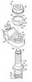
- FIG. 1is a perspective view of an apparatus constructed in accordance with the present invention
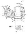
- FIG. 2is an exploded perspective view of a portion of the apparatus of FIG. 1;
- FIG. 3is a sectional view of the apparatus of FIG. 1 .
- FIGS. 1-3illustrate an apparatus 10 constructed according to the present invention.
- the apparatus 10includes a plurality of surgically implantable members 12 , one of which is shown in FIGS. 1-3.
- the members 12connect a rod 14 to bone portions (not shown), such as vertebrae of a spinal column, to maintain the bone portions in a desired spatial relationship.
- the rod 14extends along the spinal column and has a length which is at least sufficient to enable the rod to span at least two vertebrae. The length of the rod 14 in any particular installation will depend on the number of vertebrae to be held in a desired spatial relationship relative to each other by the rod.
- the spine rod 14 and member 12(FIGS. 1 and 3) are connected to a vertebra by a fastener 16 .
- the fastener 16has a threaded inner end portion 22 having a course thread convolution 24 which engages the vertebra.
- An outer end portion 26 of the fastener 16is provided with a relatively fine thread which engages an internal thread convolution on a clamping member or nut 28 .
- Wrenching flats 30are provided on the end portion 26 of the fastener 16 . Torque may be applied to the flats 30 to turn the thread convolution 24 into the vertebra and/or apply a counter torque when the clamping member 28 is threaded onto the fastener 16 .
- An intermediate portion 32 of the fastener 16has wrenching flats 34 . Torque is applied to the wrenching flats 34 to turn the threaded convolution 24 into the vertebra.
- the intermediate portion 32 (FIG. 3) of the fastener 16has an arcuate convex surface 40 which abuttingly engages the member 12 .
- the fastener 16(FIGS. 1-3) is connected to the member 12 by a connecting ring 42 .
- the member 12includes an opening 50 into which the connecting ring 42 extends.
- the outer end portion 26 of the fastener 16extends through the opening 50 .
- the connecting ring 42(FIGS. 2-3) has a passage 54 with a longitudinal axis 56 through which the outer end portion 26 of the fastener 16 extends.
- the fastener 16is positionable in any one of a plurality of angular positions relative to the connecting ring 42 so that a longitudinal axis 58 of the fastener extends at any one of a plurality of angles to the longitudinal axis 56 of the passage 54 in the connecting ring. More specifically, the fastener 16 is universally pivotable in any direction relative to the connecting ring 42 .
- the connecting ring 42has an axially extending portion 64 which extends into the opening 50 in the member 12 .
- a cylindrical outer surface 66 of the axially extending portion 64frictionally engages a cylindrical surface 70 defining the opening 50 in the member 12 .
- the connecting ring 42(FIG. 3) has an axial end surface 74 .
- the axial end surface 74engages a radially extending surface 76 on the member 12 when the axially extending portion 64 extends into the opening 50 . It is contemplated that the axial end surface 74 may not engage the surface 76 .
- the axially extending portion 64 of the connecting ring 42is pressed into the opening 50 in the member 12 to connect the connecting ring to the member. It is also contemplated that the connecting ring 42 could be formed as one piece with the member 12 .
- the connecting ring 42(FIG. 3) has an arcuate convex surface 84 .
- the arcuate convex surface 84engages an arcuate concave surface 86 on the clamping member 28 .
- the member 12has an arcuate concave surface 88 .
- the arcuate concave surface 88 on the member 12engages the arcuate convex surface 40 on the intermediate portion 32 of the fastener 16 . Accordingly, the fastener 16 is universally pivotable relative to the connecting ring 42 .
- the spine rod 14(FIGS. 1 and 3) extends through a passage 92 in the member 12 .
- a set screw or fastener 94threadably engages an opening 96 in the member 12 .
- the fastener 94engages the rod 14 to clamp the rod to the member 12 in the passage 92 .
- the fastener 16When the spine rod 14 is to be connected to a vertebra, the fastener 16 is connected to the vertebra.
- the member 12 with the connecting ring 42 connected to the memberis placed on the rod 14 and the fastener 16 with the fastener extending through the connecting ring 42 .
- the fastener 16is positioned in any one of the plurality of angular positions relative to the connecting ring 42 .
- the clamping member 28is placed on the fastener.
- the clamping member 28is threaded onto the fastener 16 to cause the member 12 to be clamped between the connecting ring 42 and the intermediate portion 32 of the fastener 16 .
- the clamping member 28also clamps the connecting ring 42 to the member 12 .
- the set screw 94is threaded into the opening 96 in the member 12 to clamp the spine rod 14 to the member.
Landscapes
- Health & Medical Sciences (AREA)
- Orthopedic Medicine & Surgery (AREA)
- Life Sciences & Earth Sciences (AREA)
- Neurology (AREA)
- Surgery (AREA)
- Heart & Thoracic Surgery (AREA)
- Engineering & Computer Science (AREA)
- Biomedical Technology (AREA)
- Nuclear Medicine, Radiotherapy & Molecular Imaging (AREA)
- Medical Informatics (AREA)
- Molecular Biology (AREA)
- Animal Behavior & Ethology (AREA)
- General Health & Medical Sciences (AREA)
- Public Health (AREA)
- Veterinary Medicine (AREA)
- Surgical Instruments (AREA)
- Prostheses (AREA)
Abstract
Description
Claims (12)
Priority Applications (1)
| Application Number | Priority Date | Filing Date | Title |
|---|---|---|---|
| US09/921,326US6673074B2 (en) | 2001-08-02 | 2001-08-02 | Apparatus for retaining bone portions in a desired spatial relationship |
Applications Claiming Priority (1)
| Application Number | Priority Date | Filing Date | Title |
|---|---|---|---|
| US09/921,326US6673074B2 (en) | 2001-08-02 | 2001-08-02 | Apparatus for retaining bone portions in a desired spatial relationship |
Publications (2)
| Publication Number | Publication Date |
|---|---|
| US20030028191A1 US20030028191A1 (en) | 2003-02-06 |
| US6673074B2true US6673074B2 (en) | 2004-01-06 |
Family
ID=25445282
Family Applications (1)
| Application Number | Title | Priority Date | Filing Date |
|---|---|---|---|
| US09/921,326Expired - Fee RelatedUS6673074B2 (en) | 2001-08-02 | 2001-08-02 | Apparatus for retaining bone portions in a desired spatial relationship |
Country Status (1)
| Country | Link |
|---|---|
| US (1) | US6673074B2 (en) |
Cited By (67)
| Publication number | Priority date | Publication date | Assignee | Title |
|---|---|---|---|---|
| US20040087949A1 (en)* | 2002-10-31 | 2004-05-06 | Bono Frank S. | Snap-in washers and assemblies thereof |
| US20040143264A1 (en)* | 2002-08-23 | 2004-07-22 | Mcafee Paul C. | Metal-backed UHMWPE rod sleeve system preserving spinal motion |
| US20050010216A1 (en)* | 2001-10-30 | 2005-01-13 | Thomas Gradel | Vertebral column support device which is assembled by means of clamping |
| US20050131411A1 (en)* | 2001-03-30 | 2005-06-16 | Culbert Brad S. | Method and apparatus for bone fixation with secondary compression |
| US20050171551A1 (en)* | 2003-10-21 | 2005-08-04 | William Sukovich | Instrument and method for preparing a bone to receive an implant |
| US20050182409A1 (en)* | 2003-05-02 | 2005-08-18 | Ronald Callahan | Systems and methods accommodating relative motion in spine stabilization |
| US20050273131A1 (en)* | 2003-08-26 | 2005-12-08 | Shluzas Alan E | Access systems and methods for minimally invasive surgery |
| US20060015105A1 (en)* | 2003-05-06 | 2006-01-19 | Christopher Warren | Proximal anchors for bone fixation system |
| US20060069404A1 (en)* | 2004-03-31 | 2006-03-30 | Shluzas Alan E | Access device having discrete visualization locations |
| WO2006045089A2 (en) | 2004-10-20 | 2006-04-27 | Endius Incorporated | An apparatus for connecting a longitudinal member to a bone portion |
| US20060149231A1 (en)* | 2004-12-13 | 2006-07-06 | Rsb Spine Llc | Bone fastener assembly for bone retention apparatus |
| US20060167455A1 (en)* | 2003-06-27 | 2006-07-27 | Mecidrea Technologies | Vertebral osteosynthesis equipment |
| US20060184170A1 (en)* | 2005-02-14 | 2006-08-17 | Altiva Corporation | Bone fixation apparatus |
| US20060200149A1 (en)* | 2005-02-22 | 2006-09-07 | Hoy Robert W | Polyaxial orhtopedic fastening apparatus |
| US20060241596A1 (en)* | 2005-04-26 | 2006-10-26 | Alan Rezach | Open dorsal adjusting connector |
| US20070173827A1 (en)* | 2006-01-20 | 2007-07-26 | Sdgi Holdings, Inc. | Adjustable connector for attachment to a rod in a medical application |
| US20070233094A1 (en)* | 2006-03-29 | 2007-10-04 | Dennis Colleran | Dynamic motion spinal stabilization system |
| US20070288026A1 (en)* | 2006-06-09 | 2007-12-13 | Endius, Inc. | Methods and apparatus for access to and/or treatment of the spine |
| US20070288012A1 (en)* | 2006-04-21 | 2007-12-13 | Dennis Colleran | Dynamic motion spinal stabilization system and device |
| US20080065073A1 (en)* | 2006-09-08 | 2008-03-13 | Michael Perriello | Offset dynamic motion spinal stabilization system |
| US20080077143A1 (en)* | 2006-09-25 | 2008-03-27 | Zimmer Spine, Inc. | Apparatus for connecting a longitudinal member to a bone portion |
| US20080177322A1 (en)* | 2006-12-29 | 2008-07-24 | Melissa Davis | Spinal stabilization systems and methods |
| US20080288002A1 (en)* | 2006-12-29 | 2008-11-20 | Abbott Spine Inc. | Spinal Stabilization Systems and Methods |
| US20080306537A1 (en)* | 2007-06-08 | 2008-12-11 | Interventional Spine, Inc. | Method and apparatus for spinal stabilization |
| US20100063546A1 (en)* | 2008-09-09 | 2010-03-11 | Warsaw Orthopedic, Inc. | Offset vertebral rod connector |
| US20100268279A1 (en)* | 2007-07-19 | 2010-10-21 | Josef Gabelberger | Clamps used for interconnecting a bone anchor to a rod |
| US7854752B2 (en) | 2004-08-09 | 2010-12-21 | Theken Spine, Llc | System and method for dynamic skeletal stabilization |
| US20100331891A1 (en)* | 2009-06-24 | 2010-12-30 | Interventional Spine, Inc. | System and method for spinal fixation |
| US8109977B2 (en) | 2002-07-19 | 2012-02-07 | Interventional Spine, Inc. | Method and apparatus for spinal fixation |
| US20120109209A1 (en)* | 2010-10-29 | 2012-05-03 | Warsaw Orthopedic, Inc. | Spinal Connector Assembly |
| US8353937B2 (en) | 2007-05-22 | 2013-01-15 | Warsaw Orthopedic, Inc. | Spinal stabilization systems and methods |
| US9314274B2 (en) | 2011-05-27 | 2016-04-19 | DePuy Synthes Products, Inc. | Minimally invasive spinal fixation system including vertebral alignment features |
| US9402663B2 (en) | 2010-04-23 | 2016-08-02 | DePuy Synthes Products, Inc. | Minimally invasive instrument set, devices and related methods |
| US9498262B2 (en) | 2006-04-11 | 2016-11-22 | DePuy Synthes Products, Inc. | Minimally invasive fixation system |
| US9522028B2 (en) | 2013-07-03 | 2016-12-20 | Interventional Spine, Inc. | Method and apparatus for sacroiliac joint fixation |
| US9522070B2 (en) | 2013-03-07 | 2016-12-20 | Interventional Spine, Inc. | Intervertebral implant |
| US9808281B2 (en) | 2009-05-20 | 2017-11-07 | DePuy Synthes Products, Inc. | Patient-mounted retraction |
| US9839530B2 (en) | 2007-06-26 | 2017-12-12 | DePuy Synthes Products, Inc. | Highly lordosed fusion cage |
| US9883951B2 (en) | 2012-08-30 | 2018-02-06 | Interventional Spine, Inc. | Artificial disc |
| US9895236B2 (en) | 2010-06-24 | 2018-02-20 | DePuy Synthes Products, Inc. | Enhanced cage insertion assembly |
| US9913727B2 (en) | 2015-07-02 | 2018-03-13 | Medos International Sarl | Expandable implant |
| US9931223B2 (en) | 2008-04-05 | 2018-04-03 | DePuy Synthes Products, Inc. | Expandable intervertebral implant |
| US9993349B2 (en) | 2002-06-27 | 2018-06-12 | DePuy Synthes Products, Inc. | Intervertebral disc |
| US10058433B2 (en) | 2012-07-26 | 2018-08-28 | DePuy Synthes Products, Inc. | Expandable implant |
| US10111695B2 (en) | 2001-03-30 | 2018-10-30 | DePuy Synthes Products, Inc. | Distal bone anchors for bone fixation with secondary compression |
| US10390963B2 (en) | 2006-12-07 | 2019-08-27 | DePuy Synthes Products, Inc. | Intervertebral implant |
| US10398563B2 (en) | 2017-05-08 | 2019-09-03 | Medos International Sarl | Expandable cage |
| US10433977B2 (en) | 2008-01-17 | 2019-10-08 | DePuy Synthes Products, Inc. | Expandable intervertebral implant and associated method of manufacturing the same |
| US10500062B2 (en) | 2009-12-10 | 2019-12-10 | DePuy Synthes Products, Inc. | Bellows-like expandable interbody fusion cage |
| US10537436B2 (en) | 2016-11-01 | 2020-01-21 | DePuy Synthes Products, Inc. | Curved expandable cage |
| US10548741B2 (en) | 2010-06-29 | 2020-02-04 | DePuy Synthes Products, Inc. | Distractible intervertebral implant |
| US10888433B2 (en) | 2016-12-14 | 2021-01-12 | DePuy Synthes Products, Inc. | Intervertebral implant inserter and related methods |
| US10940016B2 (en) | 2017-07-05 | 2021-03-09 | Medos International Sarl | Expandable intervertebral fusion cage |
| US11344424B2 (en) | 2017-06-14 | 2022-05-31 | Medos International Sarl | Expandable intervertebral implant and related methods |
| US11426286B2 (en) | 2020-03-06 | 2022-08-30 | Eit Emerging Implant Technologies Gmbh | Expandable intervertebral implant |
| US11426290B2 (en) | 2015-03-06 | 2022-08-30 | DePuy Synthes Products, Inc. | Expandable intervertebral implant, system, kit and method |
| US11446156B2 (en) | 2018-10-25 | 2022-09-20 | Medos International Sarl | Expandable intervertebral implant, inserter instrument, and related methods |
| US11452607B2 (en) | 2010-10-11 | 2022-09-27 | DePuy Synthes Products, Inc. | Expandable interspinous process spacer implant |
| US11510788B2 (en) | 2016-06-28 | 2022-11-29 | Eit Emerging Implant Technologies Gmbh | Expandable, angularly adjustable intervertebral cages |
| US11596522B2 (en) | 2016-06-28 | 2023-03-07 | Eit Emerging Implant Technologies Gmbh | Expandable and angularly adjustable intervertebral cages with articulating joint |
| US11612491B2 (en) | 2009-03-30 | 2023-03-28 | DePuy Synthes Products, Inc. | Zero profile spinal fusion cage |
| US11752009B2 (en) | 2021-04-06 | 2023-09-12 | Medos International Sarl | Expandable intervertebral fusion cage |
| US11850160B2 (en) | 2021-03-26 | 2023-12-26 | Medos International Sarl | Expandable lordotic intervertebral fusion cage |
| US11911287B2 (en) | 2010-06-24 | 2024-02-27 | DePuy Synthes Products, Inc. | Lateral spondylolisthesis reduction cage |
| USRE49973E1 (en) | 2013-02-28 | 2024-05-21 | DePuy Synthes Products, Inc. | Expandable intervertebral implant, system, kit and method |
| US12090064B2 (en) | 2022-03-01 | 2024-09-17 | Medos International Sarl | Stabilization members for expandable intervertebral implants, and related systems and methods |
| US12440346B2 (en) | 2023-03-31 | 2025-10-14 | DePuy Synthes Products, Inc. | Expandable intervertebral implant |
Families Citing this family (53)
| Publication number | Priority date | Publication date | Assignee | Title |
|---|---|---|---|---|
| US7833250B2 (en) | 2004-11-10 | 2010-11-16 | Jackson Roger P | Polyaxial bone screw with helically wound capture connection |
| JP2004505745A (en)* | 2000-08-24 | 2004-02-26 | ジンテーズ アクチエンゲゼルシャフト クール | Device for connecting a bone anchoring element to a longitudinal rod |
| US8377100B2 (en)* | 2000-12-08 | 2013-02-19 | Roger P. Jackson | Closure for open-headed medical implant |
| US6726689B2 (en)* | 2002-09-06 | 2004-04-27 | Roger P. Jackson | Helical interlocking mating guide and advancement structure |
| US8876868B2 (en)* | 2002-09-06 | 2014-11-04 | Roger P. Jackson | Helical guide and advancement flange with radially loaded lip |
| US20060009773A1 (en)* | 2002-09-06 | 2006-01-12 | Jackson Roger P | Helical interlocking mating guide and advancement structure |
| US8282673B2 (en)* | 2002-09-06 | 2012-10-09 | Jackson Roger P | Anti-splay medical implant closure with multi-surface removal aperture |
| WO2006052796A2 (en) | 2004-11-10 | 2006-05-18 | Jackson Roger P | Helical guide and advancement flange with break-off extensions |
| US8257402B2 (en)* | 2002-09-06 | 2012-09-04 | Jackson Roger P | Closure for rod receiving orthopedic implant having left handed thread removal |
| US6716214B1 (en)* | 2003-06-18 | 2004-04-06 | Roger P. Jackson | Polyaxial bone screw with spline capture connection |
| US7377923B2 (en) | 2003-05-22 | 2008-05-27 | Alphatec Spine, Inc. | Variable angle spinal screw assembly |
| US7776067B2 (en) | 2005-05-27 | 2010-08-17 | Jackson Roger P | Polyaxial bone screw with shank articulation pressure insert and method |
| US7766915B2 (en) | 2004-02-27 | 2010-08-03 | Jackson Roger P | Dynamic fixation assemblies with inner core and outer coil-like member |
| US8137386B2 (en) | 2003-08-28 | 2012-03-20 | Jackson Roger P | Polyaxial bone screw apparatus |
| US8398682B2 (en)* | 2003-06-18 | 2013-03-19 | Roger P. Jackson | Polyaxial bone screw assembly |
| US7967850B2 (en) | 2003-06-18 | 2011-06-28 | Jackson Roger P | Polyaxial bone anchor with helical capture connection, insert and dual locking assembly |
| US20100211114A1 (en)* | 2003-06-18 | 2010-08-19 | Jackson Roger P | Polyaxial bone anchor with shelf capture connection |
| US8366753B2 (en)* | 2003-06-18 | 2013-02-05 | Jackson Roger P | Polyaxial bone screw assembly with fixed retaining structure |
| US8926670B2 (en) | 2003-06-18 | 2015-01-06 | Roger P. Jackson | Polyaxial bone screw assembly |
| US7731734B2 (en)* | 2003-06-27 | 2010-06-08 | Medicrea Technologies | Vertebral osteosynthesis equipment |
| FR2860138A1 (en)* | 2003-09-26 | 2005-04-01 | Stryker Spine | ASSEMBLY AND METHOD OF FIXING BONES |
| FR2870108B1 (en)* | 2004-05-17 | 2007-06-15 | Hassan Razian | SPINAL OSTEOSYNTHESIS DEVICE FOR MAINTAINING AT LEAST TWO VERTEBRATES IN RELATION TO EACH OTHER |
| US7850719B2 (en)* | 2004-05-26 | 2010-12-14 | Warsaw Orthopedic, Inc. | Spinal implant apparatus |
| US20060058787A1 (en)* | 2004-08-24 | 2006-03-16 | Stryker Spine | Spinal implant assembly |
| US8926672B2 (en) | 2004-11-10 | 2015-01-06 | Roger P. Jackson | Splay control closure for open bone anchor |
| US9168069B2 (en) | 2009-06-15 | 2015-10-27 | Roger P. Jackson | Polyaxial bone anchor with pop-on shank and winged insert with lower skirt for engaging a friction fit retainer |
| ES2275382B1 (en)* | 2005-01-03 | 2008-06-01 | Socinser 21, S.A. | TRANSPEDICULAR VERTEBRAL FIXING SYSTEM. |
| US10076361B2 (en) | 2005-02-22 | 2018-09-18 | Roger P. Jackson | Polyaxial bone screw with spherical capture, compression and alignment and retention structures |
| US7901437B2 (en) | 2007-01-26 | 2011-03-08 | Jackson Roger P | Dynamic stabilization member with molded connection |
| JP4221032B2 (en)* | 2007-02-14 | 2009-02-12 | 昭和医科工業株式会社 | connector |
| JP4221033B2 (en)* | 2007-02-14 | 2009-02-12 | 昭和医科工業株式会社 | Vertebral connecting member and nut driver |
| US8979904B2 (en) | 2007-05-01 | 2015-03-17 | Roger P Jackson | Connecting member with tensioned cord, low profile rigid sleeve and spacer with torsion control |
| US9060813B1 (en) | 2008-02-29 | 2015-06-23 | Nuvasive, Inc. | Surgical fixation system and related methods |
| US8308775B2 (en)* | 2008-10-14 | 2012-11-13 | Medicrea International | Method for rotating a vertebra or vertebrae |
| US11229457B2 (en) | 2009-06-15 | 2022-01-25 | Roger P. Jackson | Pivotal bone anchor assembly with insert tool deployment |
| US9668771B2 (en) | 2009-06-15 | 2017-06-06 | Roger P Jackson | Soft stabilization assemblies with off-set connector |
| US9198696B1 (en) | 2010-05-27 | 2015-12-01 | Nuvasive, Inc. | Cross-connector and related methods |
| US9186184B2 (en)* | 2011-02-14 | 2015-11-17 | Pioneer Surgical Technology, Inc. | Spinal fixation system and method |
| US9387013B1 (en) | 2011-03-01 | 2016-07-12 | Nuvasive, Inc. | Posterior cervical fixation system |
| US9247964B1 (en) | 2011-03-01 | 2016-02-02 | Nuasive, Inc. | Spinal Cross-connector |
| US8911479B2 (en) | 2012-01-10 | 2014-12-16 | Roger P. Jackson | Multi-start closures for open implants |
| US8911478B2 (en) | 2012-11-21 | 2014-12-16 | Roger P. Jackson | Splay control closure for open bone anchor |
| US10058354B2 (en) | 2013-01-28 | 2018-08-28 | Roger P. Jackson | Pivotal bone anchor assembly with frictional shank head seating surfaces |
| US8852239B2 (en) | 2013-02-15 | 2014-10-07 | Roger P Jackson | Sagittal angle screw with integral shank and receiver |
| FR3004636A1 (en)* | 2013-04-19 | 2014-10-24 | Medicrea International | RECOVERY ASSEMBLY FOR VERTEBRAL OSTEOSYNTHESIS EQUIPMENT |
| US9566092B2 (en) | 2013-10-29 | 2017-02-14 | Roger P. Jackson | Cervical bone anchor with collet retainer and outer locking sleeve |
| US9717533B2 (en) | 2013-12-12 | 2017-08-01 | Roger P. Jackson | Bone anchor closure pivot-splay control flange form guide and advancement structure |
| US9451993B2 (en) | 2014-01-09 | 2016-09-27 | Roger P. Jackson | Bi-radial pop-on cervical bone anchor |
| US10064658B2 (en) | 2014-06-04 | 2018-09-04 | Roger P. Jackson | Polyaxial bone anchor with insert guides |
| US9597119B2 (en) | 2014-06-04 | 2017-03-21 | Roger P. Jackson | Polyaxial bone anchor with polymer sleeve |
| KR101910597B1 (en)* | 2016-12-02 | 2018-10-22 | 안경기 | Rod connector |
| US10258386B2 (en)* | 2017-06-15 | 2019-04-16 | Warsaw Orthopedic, Inc. | Spinal construct and method |
| US11331125B1 (en) | 2021-10-07 | 2022-05-17 | Ortho Inventions, Llc | Low profile rod-to-rod coupler |
Citations (11)
| Publication number | Priority date | Publication date | Assignee | Title |
|---|---|---|---|---|
| US5041113A (en) | 1989-07-20 | 1991-08-20 | Lutz Biedermann | Stabilization member for stabilizing bones |
| US5084048A (en) | 1989-07-12 | 1992-01-28 | Sulzer Brothers Limited | Implant for vertebrae with spinal stabilizer |
| US5129899A (en)* | 1991-03-27 | 1992-07-14 | Smith & Nephew Richards Inc. | Bone fixation apparatus |
| US5520690A (en) | 1995-04-13 | 1996-05-28 | Errico; Joseph P. | Anterior spinal polyaxial locking screw plate assembly |
| US5613968A (en) | 1995-05-01 | 1997-03-25 | Lin; Chih-I | Universal pad fixation device for orthopedic surgery |
| US5984924A (en) | 1998-10-07 | 1999-11-16 | Isola Implants, Inc. | Bone alignment system having variable orientation bone anchors |
| US6004322A (en)* | 1994-10-25 | 1999-12-21 | Sdgi Holdings, Inc. | Modular pedicle screw system |
| US6123706A (en)* | 1997-12-17 | 2000-09-26 | Lange; Robert | Apparatus for stabilizing certain vertebrae of the spine |
| FR2796546A1 (en)* | 1999-07-23 | 2001-01-26 | Eurosurgical | Polyaxial connector for spinal implant has clamp block with bore to receive threaded anchor screw fitting end and second clamp block with bore for connection rod |
| US6187005B1 (en)* | 1998-09-11 | 2001-02-13 | Synthes (Usa) | Variable angle spinal fixation system |
| US6280443B1 (en) | 1999-01-30 | 2001-08-28 | Ja-Kyo Gu | Spinal fixation system |
- 2001
- 2001-08-02USUS09/921,326patent/US6673074B2/ennot_activeExpired - Fee Related
Patent Citations (12)
| Publication number | Priority date | Publication date | Assignee | Title |
|---|---|---|---|---|
| US5084048A (en) | 1989-07-12 | 1992-01-28 | Sulzer Brothers Limited | Implant for vertebrae with spinal stabilizer |
| US5041113A (en) | 1989-07-20 | 1991-08-20 | Lutz Biedermann | Stabilization member for stabilizing bones |
| US5129899A (en)* | 1991-03-27 | 1992-07-14 | Smith & Nephew Richards Inc. | Bone fixation apparatus |
| US6004322A (en)* | 1994-10-25 | 1999-12-21 | Sdgi Holdings, Inc. | Modular pedicle screw system |
| US5520690A (en) | 1995-04-13 | 1996-05-28 | Errico; Joseph P. | Anterior spinal polyaxial locking screw plate assembly |
| US5531746A (en) | 1995-04-13 | 1996-07-02 | Fastenetix, L.L.C. | Posterior spinal polyaxial locking lateral mass screw plate assembly |
| US5613968A (en) | 1995-05-01 | 1997-03-25 | Lin; Chih-I | Universal pad fixation device for orthopedic surgery |
| US6123706A (en)* | 1997-12-17 | 2000-09-26 | Lange; Robert | Apparatus for stabilizing certain vertebrae of the spine |
| US6187005B1 (en)* | 1998-09-11 | 2001-02-13 | Synthes (Usa) | Variable angle spinal fixation system |
| US5984924A (en) | 1998-10-07 | 1999-11-16 | Isola Implants, Inc. | Bone alignment system having variable orientation bone anchors |
| US6280443B1 (en) | 1999-01-30 | 2001-08-28 | Ja-Kyo Gu | Spinal fixation system |
| FR2796546A1 (en)* | 1999-07-23 | 2001-01-26 | Eurosurgical | Polyaxial connector for spinal implant has clamp block with bore to receive threaded anchor screw fitting end and second clamp block with bore for connection rod |
Non-Patent Citations (1)
| Title |
|---|
| Pending U.S. patent application Ser. No. 09/821,666 filed Mar. 29, 2001 entitled an Apparatus for Retaining Bone Portions in a Desired Spatial Relationship, Attorney Docket No. A31-5614. |
Cited By (144)
| Publication number | Priority date | Publication date | Assignee | Title |
|---|---|---|---|---|
| US10349991B2 (en) | 2001-03-30 | 2019-07-16 | DePuy Synthes Products, Inc. | Method and apparatus for bone fixation with secondary compression |
| US20050131411A1 (en)* | 2001-03-30 | 2005-06-16 | Culbert Brad S. | Method and apparatus for bone fixation with secondary compression |
| US8715284B2 (en) | 2001-03-30 | 2014-05-06 | Interventional Spine, Inc. | Method and apparatus for bone fixation with secondary compression |
| US10111695B2 (en) | 2001-03-30 | 2018-10-30 | DePuy Synthes Products, Inc. | Distal bone anchors for bone fixation with secondary compression |
| US9408648B2 (en) | 2001-03-30 | 2016-08-09 | Interventional Spine, Inc. | Method and apparatus for bone fixation with secondary compression |
| US7094237B2 (en)* | 2001-10-30 | 2006-08-22 | Vitatech | Vertebral column support device which is assembled by means of clamping |
| US20050010216A1 (en)* | 2001-10-30 | 2005-01-13 | Thomas Gradel | Vertebral column support device which is assembled by means of clamping |
| US9993349B2 (en) | 2002-06-27 | 2018-06-12 | DePuy Synthes Products, Inc. | Intervertebral disc |
| US9713486B2 (en) | 2002-07-19 | 2017-07-25 | DePuy Synthes Products, Inc. | Method and apparatus for spinal fixation |
| US8109977B2 (en) | 2002-07-19 | 2012-02-07 | Interventional Spine, Inc. | Method and apparatus for spinal fixation |
| US8945190B2 (en) | 2002-07-19 | 2015-02-03 | Interventional Spine, Inc. | Method and apparatus for spinal fixation |
| US20040143264A1 (en)* | 2002-08-23 | 2004-07-22 | Mcafee Paul C. | Metal-backed UHMWPE rod sleeve system preserving spinal motion |
| US7306602B2 (en) | 2002-10-31 | 2007-12-11 | Depuy Actomed, Inc. | Snap-in washers and assemblies thereof |
| US20040087949A1 (en)* | 2002-10-31 | 2004-05-06 | Bono Frank S. | Snap-in washers and assemblies thereof |
| US20050182409A1 (en)* | 2003-05-02 | 2005-08-18 | Ronald Callahan | Systems and methods accommodating relative motion in spine stabilization |
| US7635379B2 (en)* | 2003-05-02 | 2009-12-22 | Applied Spine Technologies, Inc. | Pedicle screw assembly with bearing surfaces |
| US20060015105A1 (en)* | 2003-05-06 | 2006-01-19 | Christopher Warren | Proximal anchors for bone fixation system |
| US7763054B2 (en)* | 2003-06-27 | 2010-07-27 | Medicrea Technologies | Vertebral osteosynthesis equipment |
| US20060167455A1 (en)* | 2003-06-27 | 2006-07-27 | Mecidrea Technologies | Vertebral osteosynthesis equipment |
| EP2305127A1 (en) | 2003-08-26 | 2011-04-06 | Endius Incorporated | Adjustable height access device for treating the spine of a patient |
| US20050273131A1 (en)* | 2003-08-26 | 2005-12-08 | Shluzas Alan E | Access systems and methods for minimally invasive surgery |
| US7691120B2 (en) | 2003-08-26 | 2010-04-06 | Zimmer Spine, Inc. | Access systems and methods for minimally invasive surgery |
| US7976464B2 (en) | 2003-08-26 | 2011-07-12 | Zimmer Spine, Inc. | Access systems and methods for minimally invasive surgery |
| US20050171551A1 (en)* | 2003-10-21 | 2005-08-04 | William Sukovich | Instrument and method for preparing a bone to receive an implant |
| US20060069404A1 (en)* | 2004-03-31 | 2006-03-30 | Shluzas Alan E | Access device having discrete visualization locations |
| US7854752B2 (en) | 2004-08-09 | 2010-12-21 | Theken Spine, Llc | System and method for dynamic skeletal stabilization |
| US20070299444A1 (en)* | 2004-08-26 | 2007-12-27 | Endius, Inc. | Methods and apparatus for access to and/or treatment of the spine |
| US9055934B2 (en) | 2004-08-26 | 2015-06-16 | Zimmer Spine, Inc. | Methods and apparatus for access to and/or treatment of the spine |
| WO2006045089A2 (en) | 2004-10-20 | 2006-04-27 | Endius Incorporated | An apparatus for connecting a longitudinal member to a bone portion |
| US20060149231A1 (en)* | 2004-12-13 | 2006-07-06 | Rsb Spine Llc | Bone fastener assembly for bone retention apparatus |
| US7578833B2 (en) | 2004-12-13 | 2009-08-25 | Dr. Robert S. Bray, Jr. | Bone fastener assembly for bone retention apparatus |
| US20060184170A1 (en)* | 2005-02-14 | 2006-08-17 | Altiva Corporation | Bone fixation apparatus |
| US7993373B2 (en)* | 2005-02-22 | 2011-08-09 | Hoy Robert W | Polyaxial orthopedic fastening apparatus |
| US20060200149A1 (en)* | 2005-02-22 | 2006-09-07 | Hoy Robert W | Polyaxial orhtopedic fastening apparatus |
| US20060241596A1 (en)* | 2005-04-26 | 2006-10-26 | Alan Rezach | Open dorsal adjusting connector |
| US7678112B2 (en)* | 2005-04-26 | 2010-03-16 | Warsaw Orthopedic, Inc. | Open dorsal adjusting connector |
| US8167911B2 (en) | 2005-07-20 | 2012-05-01 | Zimmer Spine, Inc. | Apparatus for connecting a longitudinal member to a bone portion |
| US20070021750A1 (en)* | 2005-07-20 | 2007-01-25 | Shluzas Alan E | Apparatus for connecting a longitudinal member to a bone portion |
| US20070173827A1 (en)* | 2006-01-20 | 2007-07-26 | Sdgi Holdings, Inc. | Adjustable connector for attachment to a rod in a medical application |
| US20070233094A1 (en)* | 2006-03-29 | 2007-10-04 | Dennis Colleran | Dynamic motion spinal stabilization system |
| US8025681B2 (en) | 2006-03-29 | 2011-09-27 | Theken Spine, Llc | Dynamic motion spinal stabilization system |
| US10441325B2 (en) | 2006-04-11 | 2019-10-15 | DePuy Synthes Products, Inc. | Minimally invasive fixation system |
| US9498262B2 (en) | 2006-04-11 | 2016-11-22 | DePuy Synthes Products, Inc. | Minimally invasive fixation system |
| US20070288012A1 (en)* | 2006-04-21 | 2007-12-13 | Dennis Colleran | Dynamic motion spinal stabilization system and device |
| US7892238B2 (en) | 2006-06-09 | 2011-02-22 | Zimmer Spine, Inc. | Methods and apparatus for access to and/or treatment of the spine |
| US8123751B2 (en) | 2006-06-09 | 2012-02-28 | Zimmer Spine, Inc. | Methods and apparatus for access to and/or treatment of the spine |
| US20070288026A1 (en)* | 2006-06-09 | 2007-12-13 | Endius, Inc. | Methods and apparatus for access to and/or treatment of the spine |
| US11849931B2 (en) | 2006-06-09 | 2023-12-26 | Zimmer Biomet Spine, Inc. | Methods and apparatus for access to and/or treatment of the spine |
| US10905407B2 (en) | 2006-06-09 | 2021-02-02 | Zimmer Spine, Inc. | Methods and apparatus for access to and/or treatment of the spine |
| US20070299443A1 (en)* | 2006-06-09 | 2007-12-27 | Endius, Inc. | Methods and apparatus for access to and/or treatment of the spine |
| US20080065073A1 (en)* | 2006-09-08 | 2008-03-13 | Michael Perriello | Offset dynamic motion spinal stabilization system |
| US20080077143A1 (en)* | 2006-09-25 | 2008-03-27 | Zimmer Spine, Inc. | Apparatus for connecting a longitudinal member to a bone portion |
| US10390963B2 (en) | 2006-12-07 | 2019-08-27 | DePuy Synthes Products, Inc. | Intervertebral implant |
| US11273050B2 (en) | 2006-12-07 | 2022-03-15 | DePuy Synthes Products, Inc. | Intervertebral implant |
| US10398566B2 (en) | 2006-12-07 | 2019-09-03 | DePuy Synthes Products, Inc. | Intervertebral implant |
| US10583015B2 (en) | 2006-12-07 | 2020-03-10 | DePuy Synthes Products, Inc. | Intervertebral implant |
| US11497618B2 (en) | 2006-12-07 | 2022-11-15 | DePuy Synthes Products, Inc. | Intervertebral implant |
| US11712345B2 (en) | 2006-12-07 | 2023-08-01 | DePuy Synthes Products, Inc. | Intervertebral implant |
| US11642229B2 (en) | 2006-12-07 | 2023-05-09 | DePuy Synthes Products, Inc. | Intervertebral implant |
| US11432942B2 (en) | 2006-12-07 | 2022-09-06 | DePuy Synthes Products, Inc. | Intervertebral implant |
| US11660206B2 (en) | 2006-12-07 | 2023-05-30 | DePuy Synthes Products, Inc. | Intervertebral implant |
| US20080288002A1 (en)* | 2006-12-29 | 2008-11-20 | Abbott Spine Inc. | Spinal Stabilization Systems and Methods |
| US20080177322A1 (en)* | 2006-12-29 | 2008-07-24 | Melissa Davis | Spinal stabilization systems and methods |
| US8636783B2 (en) | 2006-12-29 | 2014-01-28 | Zimmer Spine, Inc. | Spinal stabilization systems and methods |
| US8353937B2 (en) | 2007-05-22 | 2013-01-15 | Warsaw Orthopedic, Inc. | Spinal stabilization systems and methods |
| US20080306537A1 (en)* | 2007-06-08 | 2008-12-11 | Interventional Spine, Inc. | Method and apparatus for spinal stabilization |
| US7998176B2 (en) | 2007-06-08 | 2011-08-16 | Interventional Spine, Inc. | Method and apparatus for spinal stabilization |
| US9839530B2 (en) | 2007-06-26 | 2017-12-12 | DePuy Synthes Products, Inc. | Highly lordosed fusion cage |
| US10973652B2 (en) | 2007-06-26 | 2021-04-13 | DePuy Synthes Products, Inc. | Highly lordosed fusion cage |
| US11622868B2 (en) | 2007-06-26 | 2023-04-11 | DePuy Synthes Products, Inc. | Highly lordosed fusion cage |
| US20100268279A1 (en)* | 2007-07-19 | 2010-10-21 | Josef Gabelberger | Clamps used for interconnecting a bone anchor to a rod |
| US8585741B2 (en) | 2007-07-19 | 2013-11-19 | DePuy Synthes Products, LLC | Clamps used for interconnecting a bone anchor to a rod |
| US10449058B2 (en) | 2008-01-17 | 2019-10-22 | DePuy Synthes Products, Inc. | Expandable intervertebral implant and associated method of manufacturing the same |
| US11737881B2 (en) | 2008-01-17 | 2023-08-29 | DePuy Synthes Products, Inc. | Expandable intervertebral implant and associated method of manufacturing the same |
| US10433977B2 (en) | 2008-01-17 | 2019-10-08 | DePuy Synthes Products, Inc. | Expandable intervertebral implant and associated method of manufacturing the same |
| US11701234B2 (en) | 2008-04-05 | 2023-07-18 | DePuy Synthes Products, Inc. | Expandable intervertebral implant |
| US10449056B2 (en) | 2008-04-05 | 2019-10-22 | DePuy Synthes Products, Inc. | Expandable intervertebral implant |
| US9931223B2 (en) | 2008-04-05 | 2018-04-03 | DePuy Synthes Products, Inc. | Expandable intervertebral implant |
| US12023255B2 (en) | 2008-04-05 | 2024-07-02 | DePuy Synthes Products, Inc. | Expandable inter vertebral implant |
| US9993350B2 (en) | 2008-04-05 | 2018-06-12 | DePuy Synthes Products, Inc. | Expandable intervertebral implant |
| US11602438B2 (en) | 2008-04-05 | 2023-03-14 | DePuy Synthes Products, Inc. | Expandable intervertebral implant |
| US11707359B2 (en) | 2008-04-05 | 2023-07-25 | DePuy Synthes Products, Inc. | Expandable intervertebral implant |
| US11617655B2 (en) | 2008-04-05 | 2023-04-04 | DePuy Synthes Products, Inc. | Expandable intervertebral implant |
| US11712341B2 (en) | 2008-04-05 | 2023-08-01 | DePuy Synthes Products, Inc. | Expandable intervertebral implant |
| US12011361B2 (en) | 2008-04-05 | 2024-06-18 | DePuy Synthes Products, Inc. | Expandable intervertebral implant |
| US11712342B2 (en) | 2008-04-05 | 2023-08-01 | DePuy Synthes Products, Inc. | Expandable intervertebral implant |
| US8147523B2 (en) | 2008-09-09 | 2012-04-03 | Warsaw Orthopedic, Inc. | Offset vertebral rod connector |
| US20100063546A1 (en)* | 2008-09-09 | 2010-03-11 | Warsaw Orthopedic, Inc. | Offset vertebral rod connector |
| US12097124B2 (en) | 2009-03-30 | 2024-09-24 | DePuy Synthes Products, Inc. | Zero profile spinal fusion cage |
| US11612491B2 (en) | 2009-03-30 | 2023-03-28 | DePuy Synthes Products, Inc. | Zero profile spinal fusion cage |
| US12349936B2 (en) | 2009-05-20 | 2025-07-08 | DePuy Synthes Products, Inc. | Patient-mounted retraction |
| US10993739B2 (en) | 2009-05-20 | 2021-05-04 | DePuy Synthes Products, Inc. | Patient-mounted retraction |
| US9808281B2 (en) | 2009-05-20 | 2017-11-07 | DePuy Synthes Products, Inc. | Patient-mounted retraction |
| US20100331891A1 (en)* | 2009-06-24 | 2010-12-30 | Interventional Spine, Inc. | System and method for spinal fixation |
| US11607321B2 (en) | 2009-12-10 | 2023-03-21 | DePuy Synthes Products, Inc. | Bellows-like expandable interbody fusion cage |
| US10500062B2 (en) | 2009-12-10 | 2019-12-10 | DePuy Synthes Products, Inc. | Bellows-like expandable interbody fusion cage |
| US10888360B2 (en) | 2010-04-23 | 2021-01-12 | DePuy Synthes Products, Inc. | Minimally invasive instrument set, devices, and related methods |
| US11389213B2 (en) | 2010-04-23 | 2022-07-19 | DePuy Synthes Products, Inc. | Minimally invasive instrument set, devices, and related methods |
| US9402663B2 (en) | 2010-04-23 | 2016-08-02 | DePuy Synthes Products, Inc. | Minimally invasive instrument set, devices and related methods |
| US12318304B2 (en) | 2010-06-24 | 2025-06-03 | DePuy Synthes Products, Inc. | Lateral spondylolisthesis reduction cage |
| US10966840B2 (en) | 2010-06-24 | 2021-04-06 | DePuy Synthes Products, Inc. | Enhanced cage insertion assembly |
| US9895236B2 (en) | 2010-06-24 | 2018-02-20 | DePuy Synthes Products, Inc. | Enhanced cage insertion assembly |
| US11872139B2 (en) | 2010-06-24 | 2024-01-16 | DePuy Synthes Products, Inc. | Enhanced cage insertion assembly |
| US11911287B2 (en) | 2010-06-24 | 2024-02-27 | DePuy Synthes Products, Inc. | Lateral spondylolisthesis reduction cage |
| US10548741B2 (en) | 2010-06-29 | 2020-02-04 | DePuy Synthes Products, Inc. | Distractible intervertebral implant |
| US11654033B2 (en) | 2010-06-29 | 2023-05-23 | DePuy Synthes Products, Inc. | Distractible intervertebral implant |
| US11452607B2 (en) | 2010-10-11 | 2022-09-27 | DePuy Synthes Products, Inc. | Expandable interspinous process spacer implant |
| US8246658B2 (en)* | 2010-10-29 | 2012-08-21 | Warsaw Orthopedic, Inc. | Spinal connector assembly |
| US20120109209A1 (en)* | 2010-10-29 | 2012-05-03 | Warsaw Orthopedic, Inc. | Spinal Connector Assembly |
| US10098666B2 (en) | 2011-05-27 | 2018-10-16 | DePuy Synthes Products, Inc. | Minimally invasive spinal fixation system including vertebral alignment features |
| US9314274B2 (en) | 2011-05-27 | 2016-04-19 | DePuy Synthes Products, Inc. | Minimally invasive spinal fixation system including vertebral alignment features |
| US10058433B2 (en) | 2012-07-26 | 2018-08-28 | DePuy Synthes Products, Inc. | Expandable implant |
| US9883951B2 (en) | 2012-08-30 | 2018-02-06 | Interventional Spine, Inc. | Artificial disc |
| USRE49973E1 (en) | 2013-02-28 | 2024-05-21 | DePuy Synthes Products, Inc. | Expandable intervertebral implant, system, kit and method |
| US10413422B2 (en) | 2013-03-07 | 2019-09-17 | DePuy Synthes Products, Inc. | Intervertebral implant |
| US11850164B2 (en) | 2013-03-07 | 2023-12-26 | DePuy Synthes Products, Inc. | Intervertebral implant |
| US11497619B2 (en) | 2013-03-07 | 2022-11-15 | DePuy Synthes Products, Inc. | Intervertebral implant |
| US9522070B2 (en) | 2013-03-07 | 2016-12-20 | Interventional Spine, Inc. | Intervertebral implant |
| US10166056B2 (en) | 2013-07-03 | 2019-01-01 | DePuy Synthes Products, Inc. | Method and apparatus for sacroiliac joint fixation |
| US9522028B2 (en) | 2013-07-03 | 2016-12-20 | Interventional Spine, Inc. | Method and apparatus for sacroiliac joint fixation |
| US11006991B2 (en) | 2013-07-03 | 2021-05-18 | DePuy Synthes Products, Inc. | Method and apparatus for sacroiliac joint fixation |
| US11426290B2 (en) | 2015-03-06 | 2022-08-30 | DePuy Synthes Products, Inc. | Expandable intervertebral implant, system, kit and method |
| US9913727B2 (en) | 2015-07-02 | 2018-03-13 | Medos International Sarl | Expandable implant |
| US12390343B2 (en) | 2016-06-28 | 2025-08-19 | Eit Emerging Implant Technologies Gmbh | Expandable, angularly adjustable intervertebral cages |
| US11596523B2 (en) | 2016-06-28 | 2023-03-07 | Eit Emerging Implant Technologies Gmbh | Expandable and angularly adjustable articulating intervertebral cages |
| US12433757B2 (en) | 2016-06-28 | 2025-10-07 | Eit Emerging Implant Technologies Gmbh | Expandable, angularly adjustable and articulating intervertebral cages |
| US11510788B2 (en) | 2016-06-28 | 2022-11-29 | Eit Emerging Implant Technologies Gmbh | Expandable, angularly adjustable intervertebral cages |
| US11596522B2 (en) | 2016-06-28 | 2023-03-07 | Eit Emerging Implant Technologies Gmbh | Expandable and angularly adjustable intervertebral cages with articulating joint |
| US10537436B2 (en) | 2016-11-01 | 2020-01-21 | DePuy Synthes Products, Inc. | Curved expandable cage |
| US10888433B2 (en) | 2016-12-14 | 2021-01-12 | DePuy Synthes Products, Inc. | Intervertebral implant inserter and related methods |
| US10398563B2 (en) | 2017-05-08 | 2019-09-03 | Medos International Sarl | Expandable cage |
| US12427031B2 (en) | 2017-05-08 | 2025-09-30 | Medos International Sarl | Expandable cage |
| US11446155B2 (en) | 2017-05-08 | 2022-09-20 | Medos International Sarl | Expandable cage |
| US11344424B2 (en) | 2017-06-14 | 2022-05-31 | Medos International Sarl | Expandable intervertebral implant and related methods |
| US10940016B2 (en) | 2017-07-05 | 2021-03-09 | Medos International Sarl | Expandable intervertebral fusion cage |
| US11446156B2 (en) | 2018-10-25 | 2022-09-20 | Medos International Sarl | Expandable intervertebral implant, inserter instrument, and related methods |
| US11426286B2 (en) | 2020-03-06 | 2022-08-30 | Eit Emerging Implant Technologies Gmbh | Expandable intervertebral implant |
| US11806245B2 (en) | 2020-03-06 | 2023-11-07 | Eit Emerging Implant Technologies Gmbh | Expandable intervertebral implant |
| US11850160B2 (en) | 2021-03-26 | 2023-12-26 | Medos International Sarl | Expandable lordotic intervertebral fusion cage |
| US11752009B2 (en) | 2021-04-06 | 2023-09-12 | Medos International Sarl | Expandable intervertebral fusion cage |
| US12023258B2 (en) | 2021-04-06 | 2024-07-02 | Medos International Sarl | Expandable intervertebral fusion cage |
| US12090064B2 (en) | 2022-03-01 | 2024-09-17 | Medos International Sarl | Stabilization members for expandable intervertebral implants, and related systems and methods |
| US12440248B2 (en) | 2022-06-28 | 2025-10-14 | DePuy Synthes Products, Inc. | Minimally invasive instrument set, devices, and related methods |
| US12440346B2 (en) | 2023-03-31 | 2025-10-14 | DePuy Synthes Products, Inc. | Expandable intervertebral implant |
Also Published As
| Publication number | Publication date |
|---|---|
| US20030028191A1 (en) | 2003-02-06 |
Similar Documents
| Publication | Publication Date | Title |
|---|---|---|
| US6673074B2 (en) | Apparatus for retaining bone portions in a desired spatial relationship | |
| US6641583B2 (en) | Apparatus for retaining bone portions in a desired spatial relationship | |
| US6837889B2 (en) | Apparatus for connecting a longitudinal member to a bone portion | |
| US10219835B2 (en) | Systems and devices for connecting a longitudinal member to a bone portion | |
| US5476463A (en) | Spinal column retaining apparatus | |
| US5741255A (en) | Spinal column retaining apparatus | |
| US20030153911A1 (en) | Apparatus for connecting a longitudinal member to a bone portion | |
| EP1087711B1 (en) | Device for securing spinal rods | |
| KR100663228B1 (en) | Bone screw | |
| US6258090B1 (en) | Closure for open ended medical implant and removal tool | |
| US6423064B1 (en) | Orthopaedic screw variable angle connection to a longitudinal support | |
| US5360429A (en) | Device for straightening, fixing, compressing, and elongating cervical vertebrae | |
| US6206879B1 (en) | Osteosynthetic holding system | |
| US20020143327A1 (en) | Transverse connector for use in spinal corrective surgery | |
| US6709434B1 (en) | Spinal osteosynthesis device | |
| JP3188306B2 (en) | A coupling for adjustably coupling the first structural element to the second structural element, in particular to a tube or rod for a fixing device | |
| US8998902B2 (en) | Multi-pin clamp and rod attachment | |
| EP1101449B1 (en) | A device for stabilizing or, respectively, compressing or distracting portions of the spinal column | |
| AU2002214650B2 (en) | Connector for spinal rod and vertebral anchor | |
| EP1119304B1 (en) | Device for securing spinal rods | |
| EP0584179A1 (en) | A clamp for use in spinal surgery | |
| EP0553424A1 (en) | Spinal column retaining apparatus | |
| WO2007022790A1 (en) | An osteosynthetic clamp for attaching a bone anchor to a support rod | |
| AU713325B2 (en) | Fastener | |
| JP3002647B2 (en) | Connection element for fixing rod to pedicle screw |
Legal Events
| Date | Code | Title | Description |
|---|---|---|---|
| AS | Assignment | Owner name:ENDIUS INCORPORATED, MASSACHUSETTS Free format text:ASSIGNMENT OF ASSIGNORS INTEREST;ASSIGNOR:SHLUZAS, ALAN E.;REEL/FRAME:012045/0743 Effective date:20010801 | |
| FEPP | Fee payment procedure | Free format text:PAT HOLDER NO LONGER CLAIMS SMALL ENTITY STATUS, ENTITY STATUS SET TO UNDISCOUNTED (ORIGINAL EVENT CODE: STOL); ENTITY STATUS OF PATENT OWNER: LARGE ENTITY | |
| FEPP | Fee payment procedure | Free format text:PAYOR NUMBER ASSIGNED (ORIGINAL EVENT CODE: ASPN); ENTITY STATUS OF PATENT OWNER: LARGE ENTITY Free format text:PAYER NUMBER DE-ASSIGNED (ORIGINAL EVENT CODE: RMPN); ENTITY STATUS OF PATENT OWNER: LARGE ENTITY | |
| FPAY | Fee payment | Year of fee payment:4 | |
| AS | Assignment | Owner name:ZIMMER SPINE, INC., MINNESOTA Free format text:MERGER;ASSIGNOR:ENDIUS INCORPORATED;REEL/FRAME:022143/0280 Effective date:20071221 Owner name:ZIMMER SPINE, INC.,MINNESOTA Free format text:MERGER;ASSIGNOR:ENDIUS INCORPORATED;REEL/FRAME:022143/0280 Effective date:20071221 | |
| FPAY | Fee payment | Year of fee payment:8 | |
| REMI | Maintenance fee reminder mailed | ||
| LAPS | Lapse for failure to pay maintenance fees | ||
| STCH | Information on status: patent discontinuation | Free format text:PATENT EXPIRED DUE TO NONPAYMENT OF MAINTENANCE FEES UNDER 37 CFR 1.362 | |
| FP | Lapsed due to failure to pay maintenance fee | Effective date:20160106 |