US6673060B1 - Drainage catheter and method for forming same - Google Patents
Drainage catheter and method for forming sameDownload PDFInfo
- Publication number
- US6673060B1 US6673060B1US09/557,665US55766500AUS6673060B1US 6673060 B1US6673060 B1US 6673060B1US 55766500 AUS55766500 AUS 55766500AUS 6673060 B1US6673060 B1US 6673060B1
- Authority
- US
- United States
- Prior art keywords
- elongated hollow
- drainage tube
- filament
- distal end
- hollow drainage
- Prior art date
- Legal status (The legal status is an assumption and is not a legal conclusion. Google has not performed a legal analysis and makes no representation as to the accuracy of the status listed.)
- Expired - Lifetime
Links
Images


Classifications
- A—HUMAN NECESSITIES
- A61—MEDICAL OR VETERINARY SCIENCE; HYGIENE
- A61M—DEVICES FOR INTRODUCING MEDIA INTO, OR ONTO, THE BODY; DEVICES FOR TRANSDUCING BODY MEDIA OR FOR TAKING MEDIA FROM THE BODY; DEVICES FOR PRODUCING OR ENDING SLEEP OR STUPOR
- A61M25/00—Catheters; Hollow probes
- A61M25/01—Introducing, guiding, advancing, emplacing or holding catheters
- A61M25/02—Holding devices, e.g. on the body
- A61M25/04—Holding devices, e.g. on the body in the body, e.g. expansible
- A—HUMAN NECESSITIES
- A61—MEDICAL OR VETERINARY SCIENCE; HYGIENE
- A61M—DEVICES FOR INTRODUCING MEDIA INTO, OR ONTO, THE BODY; DEVICES FOR TRANSDUCING BODY MEDIA OR FOR TAKING MEDIA FROM THE BODY; DEVICES FOR PRODUCING OR ENDING SLEEP OR STUPOR
- A61M1/00—Suction or pumping devices for medical purposes; Devices for carrying-off, for treatment of, or for carrying-over, body-liquids; Drainage systems
- A61M1/84—Drainage tubes; Aspiration tips
- A—HUMAN NECESSITIES
- A61—MEDICAL OR VETERINARY SCIENCE; HYGIENE
- A61B—DIAGNOSIS; SURGERY; IDENTIFICATION
- A61B17/00—Surgical instruments, devices or methods
- A61B17/04—Surgical instruments, devices or methods for suturing wounds; Holders or packages for needles or suture materials
- A61B17/0483—Hand-held instruments for holding sutures
- A—HUMAN NECESSITIES
- A61—MEDICAL OR VETERINARY SCIENCE; HYGIENE
- A61M—DEVICES FOR INTRODUCING MEDIA INTO, OR ONTO, THE BODY; DEVICES FOR TRANSDUCING BODY MEDIA OR FOR TAKING MEDIA FROM THE BODY; DEVICES FOR PRODUCING OR ENDING SLEEP OR STUPOR
- A61M27/00—Drainage appliance for wounds or the like, i.e. wound drains, implanted drains
Definitions
- the present inventionrelates in general to drainage catheters and, more particularly, to a drainage catheter for draining fluid from a body cavity of a patient.
- Drainage catheters for draining fluid from a body cavity of a patienthave been known in the art for many years. Indeed, the practice of inserting a drainage catheter into a body cavity has become a routine medical procedure. Generally, the catheter is inserted into the patient's body cavity with the aid of insertion tools, such as a needle or stiffening cannula. Once in position, the shape of the flexible tip at the end of the cavity is typically altered to maintain the tip within the cavity, and, in turn, to preclude inadvertent removal of the drainage catheter from the patient's body.
- Various ones of these locking cathetershave been developed with the capacity to form J-shape, pigtail or other loops at their distal end.
- the loopis typically formed by retracting a flexible tensioning member, which extends from a distal end down the length of the catheter to a proximal end, where the tensioning member typically exits the catheter.
- the tensioning memberis typically locked into place and sealed at the exit point by a retention member.
- a tensioning memberin the form of a flexible suture, is capable of forming a loop in the distal end of the catheter.
- the sutureextends through the catheter to the proximal end thereof, where it exits the catheter through a suture exit point.
- An annular latex sleevecovers the outer surface of the catheter near its proximal end to, in turn, cover the suture exit, thus helping to seal the catheter from leakage.
- an annular silicone sleeveis then rolled over the latex sleeve to both secure the suture in a locked position, and to further minimize leakage.
- the lockable connectorincludes a resilient sleeve having a channel for housing the string and a string exit port.
- the connectorfurther includes a pivotably attached lever with a cam surface at its sealing end positioned adjacent the sleeve. Pivoting the lever compresses the sleeve, thus locking the tensioning string and the flexible tip in a desired loop orientation. Further, the lever functions to seal the string exit point in the catheter from leakage.
- Plishka, et al.U.S. Pat. No. 5,989,241, incorporated herein by reference, discloses a drainage catheter apparatus having a hub member through which a tensioning drawstring exits the catheter.
- the hubincludes a sealing member constructed of elastomeric material to seal the drawstring opening and to automatically seal the passage of fluid therethrough, while also enabling extension of the flexible drawing member to lock the distal end of the catheter in a looped configuration.
- Still other prior art locking cathetersrequire threading of a string or flexible tensioning member through multiple openings in the distal end of the catheter, to form a loop which is suitable for coiling the distal end of the catheter.
- a portion of the stringis threaded outside the distal end of the catheter to facilitate curling of the flexible tip by mere tensioning of the string.
- a looped threading patternoften requires considerable time and effort in the manufacturing process.
- the stringmust be extended from the proximal end, all the way through the catheter body, out the flexible tip, outside a portion of the distal end, back through the distal end, and back to the proximal end of the catheter.
- the Pieri catheterincludes a metal ring positioned in the distal end thereof for securing a tensioning string therein.
- the stringmay be pulled through an exit point in the proximal end of the catheter, thus either guiding or curling the tip of the catheter.
- Wallaceanchors a flexible member in the tip of a Malecot catheter.
- the flexible memberis anchored in the tip of the catheter with a plug, which is permanently affixed therein.
- the distal end of the catheteris pulled toward the proximal end of the catheter, thus extending winged ribs to form drainage openings for drainage of fluids from a body cavity.
- Still other referenceshave disclosed anchoring or securing a tensioning member or wire in the tip of a catheter to facilitate steering of the catheter through a patient's body, including Truckai, U.S. Pat. No. 5,397,304, That, et al, U.S. Pat. No. 5,391,146, Savage, U.S. Pat. No. 5,368,564, Stevens-Wright, U.S. Pat. No. 5,383,852 and Brennen, et al., U.S. Pat. No. 5,439,006.
- These referencesgenerally disclose steering catheters with a closed end for probing desired parts of a patient's body. Many of these catheters contain electrodes in a closed distal end to take readings or vital signs from the heart region of a patient's body.
- these catheterswork well in a particular context, these catheters are not designed to drain body fluid from a patient. Specifically, the flow of body fluid through an electrode containing flexible tip may damage the ability of the catheter to perform its intended function. Additionally, the steering wire is often permanently anchored in the flexible tip at multiple points, and thus not intended to be removed from those catheters.
- a drainage catheterwhich contains a tensioning member exit point which is liquid tight both during curling of the flexible tip and after curling of the flexible tip. Furthermore, it is desired to provide a liquid-tight seal without additional sleeves, assemblies or other catheter components.
- the present inventionis directed to a drainage catheter comprising an elongated hollow drainage tube having a proximal end, a distal end, a tip and a flexible region adjacent the tip, a filament routing channel, a hub associated with the proximal end of the elongated hollow drainage tube, and a filament member associated with the distal end for altering the shape of the flexible region to facilitate retention of the drainage tube in a patient's body.
- the filament memberis preferably slidably positioned within the filament routing channel in the distal end of the drainage tube to permit removal of the filament member from the catheter.
- the drainage catheterfurther includes an insert member which is formed into the distal end of the elongated hollow drainage tube to form the filament routing channel.
- the insert memberis preferably constructed from a plastic of a higher durometer than that forming the elongated hollow drainage tube, yet which is still chemically bonded and/or fused to the inside of the drainage tube.
- the insert memberis formed of the same material as the drainage tube, thus melt-flowing into the outer drainage tube.
- the insert memberis formed from a material distinct from the drainage tube, such as stainless steel.
- the drainage catheteris formed with a second insert member to alter the orientation of the filament member in the distal end of the elongated hollow drainage tube.
- the filament memberremains inside the elongated hollow drainage tube until exiting through the hub.
- the filament memberextends outside at least a portion of the drainage tube to facilitate alteration of the shape of the distal end of the drainage tube.
- the filament memberpreferably exits the catheter through the hub, which further includes at least one filament member passageway.
- the at least one filament member passagewayenables slidable movement of the filament member therein, while also maintaining a liquid tight seal substantially precluding leakage through the hub.
- the present inventionalso addresses a method for manufacturing the drainage catheter including the steps of positioning the filament member inside the distal end of the elongated hollow drainage tube, energizing the distal end of the elongated hollow drainage tube to form a filament routing channel positioned within the distal end such that the filament member is positioned within and slidably routed through said filament routing channel, running the filament member through at least a portion of said elongated hollow drainage tube such that the filament member emanates from the proximal end of the drainage tube, and forming a hub on the proximal end of said elongated hollow drainage tube.
- the methodfurther includes the step of associating the filament member with the insert member occurs before the step of positioning the filament member inside said distal end of the elongated hollow drainage tube.
- the step of positioning the filament member inside the distal end of the elongated hollow drainage tubefurther includes orienting the insert member and the filament member inside the distal end of the elongated hollow drainage tube.
- the step of orienting the insert member and the filament member inside the distal end of the elongated hollow drainage tubeprovides the filament member with an orientation relative to the inside surface of the elongated hollow drainage tube
- the methodfurther includes the step of positioning the filament member relative to a second insert member inside the distal end of the elongated hollow drainage tube to alter the orientation of the filament member relative to the inside surface of the elongated hollow drainage tube.
- the step of positioning the insert member and filament member inside the distal end of the elongated hollow drainage tubefurther includes the steps of positioning the insert member on a smaller diameter portion of a mandrel which includes a smaller diameter portion and a larger diameter portion, placing the elongated hollow drainage tube over the insert member and the filament member such that the insert member is inside the distal end of the elongated hollow drainage tube and such that the filament member runs inside the elongated hollow drainage tube.
- the method for forming a drainage catheterfurther includes the step of forming the distal end of the elongated hollow drainage tube to a desired shape, and which step preferably further includes inserting the distal end of the elongated hollow drainage tube into a die.
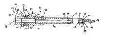
- FIG. 1is a perspective view of the drainage catheter according to the present invention
- FIG. 2is a perspective view of the drainage catheter as shown in FIG. 1, but with a portion of the filament member extending outside the distal end to lock the flexible region in a coiled orientation;
- FIG. 3is a side elevational view in cross-section of the drainage catheter shown in FIG. 1, taken along lines 3 — 3 ;
- FIG. 4is a top elevational view in cross-section of the drainage catheter as shown in FIG. 1 with the flexible region in a curled orientation, taken along lines 4 — 4 ;
- FIG. 5is a side elevational view shown in cross-section of a portion of the drainage catheter as shown in FIG. 3;
- FIG. 6is a fragmentary perspective view of a portion of the securing member of the drainage catheter as shown in FIG. 1;
- FIG. 7is a perspective view of the drainage catheter according to another embodiment of the invention.
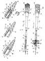
- FIG. 8is a perspective view of the mandrel, insert member and filament member used in manufacturing the drainage catheter of the present invention.
- FIG. 9is a perspective view of the elongated hollow drainage tube being positioned on the mandrel relative to the filament member and insert member according to the present invention.
- FIG. 10is a perspective view of the elongated hollow drainage tube being further positioned on the mandrel relative to the filament member and insert member according to the present invention
- FIG. 11is a perspective view of the formation of the tip of the drainage catheter according to the present invention.
- FIG. 12is a side elevational view in cross-section of the tip of the drainage catheter shown in FIG. 1;
- FIG. 13is a side elevational view in cross-section of the tip of the drainage catheter according to another embodiment of the present invention.
- FIG. 14is side elevational view in cross-section of the tip according to still another embodiment of the present invention.
- FIG. 15is a perspective view of a Malecot drainage catheter according to the present invention.
- FIG. 16is a perspective view of the Malecot catheter shown in FIG. 13 with the tip in a retracted orientation.
- Drainage catheter 20is shown in FIGS. 1-6 as comprising elongated hollow drainage tube 22 , filament member 24 , hub 26 and securing member 28 .
- drainage catheter 20will be shown and described as a locking-type catheter wherein a flexible tensioning member affirmatively alters the shape of the flexible tip of the drainage catheter to retain the same inside the body cavity of a patient.
- the distal end of the drainage cathetermay be at least partially pre-formed or pre-altered to facilitate alteration of the tip to a looped, curled, coiled or other desired orientation.
- a stiffening cannulais preferably used for insertion of the drainage catheter into a patient's body, as is well known in the art and described below.
- like reference numeralswill be used to designate like parts.
- Elongated hollow drainage tube 22shown in FIGS. 1-4, comprises proximal end 30 , distal end 32 , insert member 34 , inner tube wall surface 36 and outer tube wall surface 38 .
- Elongated hollow drainage tube 22is preferably flexible to facilitate manipulation of the elongated hollow drainage tube within a patient's body.
- elongated hollow drainage tube 22is preferably formed from a plastic and/or polymer, preferably polyurethane sold under the trade name Tecoflex.
- Tecoflexpreferably polyurethane sold under the trade name Tecoflex.
- the elongated hollow drainage tubemust be durable and non-reactive to bodily fluids coming into contact with the drainage tube, while at the same time remaining malleable and flexible to a accommodate a patient's cavities, passageways and movements.
- Distal end 32includes flexible tip 40 , drainage openings 42 and filament routing channel 66 . While the actual tip of the drainage catheter need not be flexible, the general tip region is preferably flexible to facilitate alteration thereof. Thus, the tip will be referred to as a flexible tip throughout the specification.
- Flexible tip 40further includes fluid opening 44 at the distal end of conical portion 46 . Fluid opening 44 extends through conical portion 46 of flexible tip 40 so as to be in fluid communication with the inside of elongated hollow drainage tube 22 .
- Flexible tip 40is preferably capable of being altered to any number of orientations, including a J-curl (FIG. 4 ), pigtail loop (FIG.
- the degree of curlis dependent on construction and orientation of drainage catheter 20 , including the specific threading pattern of filament member 24 , the amount of tension placed on filament member 24 , the length of elongated hollow drainage tube 22 , the flexibility of the catheter material, etc.
- flexible tip 40is shown in the drawings as having a conical shape to facilitate insertion of the drainage catheter into a patient's body, the tip may take any shape as would be known by those of ordinary skill in the art with the present disclosure before them.
- Drainage openings 42are of a size and diameter to facilitate flow of fluids from a patient's body cavity, as known by those with ordinary skill in the art with the present disclosure before them. Accordingly, the size of drainage openings 42 may be altered to accommodate a specific drainage application.
- drainage openings 42serve to facilitate drainage of fluid from a patient's body cavity
- drainage openings 42may also function to provide a threading hole for filament member 24 , as will be described below.
- fluid opening 44 in flexible tip 40is sufficient to drain fluid from a patient's body cavity, drainage openings 42 may be unnecessary.
- Filament routing channel 66is shown in FIGS. 3, 4 and 12 as being positioned between insert member 34 and inner tube wall surface 36 . As is described below, filament routing channel 66 is formed upon positioning and forming of insert member 34 into distal end 32 of elongated hollow drainage tube 22 . Thus, filament routing channel 66 is preferably formed around filament member 24 . However, filament routing channel 66 is of a sufficient diameter to permit slidable movement of filament member 24 therethrough. To this end, filament member 24 is of a higher melting point than at least one of elongated hollow drainage tube 22 and insert member 34 , such that a portion of one or both of the drainage tube and the insert member preferably melt flows around at least a portion of the filament member.
- Insert member 34is shown in FIGS. 3, 4 and 14 as comprising an annular ring with opening 48 .
- Insert member 34is preferably also constructed of a polymer plastic, preferably also a polyurethane sold under the name Tecoflex, but is preferably harder than the elongated hollow drainage tube 22 .
- insert member 34is preferably constructed of a higher durometer plastic than the plastic which forms elongated hollow drainage tube 22 .
- insert member 34is preferably formed from the same family of materials as is elongated hollow drainage tube 22 , such that insert member 34 will bond to elongated hollow drainage tube 22 upon application of sufficient heat.
- insert member 34melt flows into or chemically bonds with elongated hollow drainage tube 22 during the formation of distal end 32 and flexible tip 40 .
- insert member 34is preferably of a stronger material so as to increase the integrity of filament routing channel 66 , and to provide a secure anchor in distal end 32 for filament member 24 to slide around and/or through.
- insert membermay be formed from the same material as elongated hollow drainage tube 22 .
- insert member 34 and elongated hollow drainage tube 22will share the same melting point, thus likewise permitting insert member 34 to be bonded directly into flexible tip 40 during the formation and shaping of flexible tip 40 .
- insert member 34still provides filament routing channel 66 and a secure anchor for filament member 24 to slide around and/or through.
- insert member 34may be constructed from a completely different material than elongated hollow drainage tube 22 , such as stainless steel, other polymers or plastics or other metallic alloys. With an insert member 34 that does not chemically bond to elongated hollow drainage tube 22 , the insert member may be molded inside flexible tip 40 during formation of the flexible tip. Additionally, the use of stainless steel or other metallic alloys in construction of insert member 34 may allow the insert member to also function as a radiopaque marker for use under x-ray or fluoroscopy. Of course, elongated hollow drainage tube 22 may also include such a marking element, or may likewise be treated with a different marker, such as barium sulfate.
- Opening 48 in insert member 34permits threading of filament member 24 through the insert member prior to placement of insert member 34 into flexible tip 40 , and prior to formation of the flexible tip. Moreover, upon formation of flexible tip 40 , opening 48 permits drainage of fluids from a body cavity through fluid opening 44 , through flexible tip 40 and into elongated hollow drainage tube 22 . Thus, the number of drainage openings may be minimized, or completely eliminated altogether, depending on catheter application. However, it is likewise contemplated that insert member 34 may take the form of a substantially solid plug (not shown in the drawings) which likewise acts as an attachment and anchor point for filament member 24 .
- filament member 24is molded directly into insert member 34 .
- a solid insert memberwould mandate drainage openings in elongated hollow drainage tube 22 , such as drainage openings 42 shown in FIGS. 1 and 2, to facilitate drainage of bodily fluids through the elongated hollow drainage tube.
- Filament member 24is shown in FIGS. 1-14 as comprising first segment 62 and second segment 64 . As can be seen from FIGS. 8-11, filament member 24 is preferably threaded through insert member 34 prior to formation of distal end 32 of elongated hollow drainage tube 22 of drainage catheter 20 .
- Filament member 24is preferably constructed from a nylon mono-filament line; however, those of ordinary skill in the art with the present disclosure before will appreciate that filament member 24 may likewise be made from wire, stainless steel, plastic or other polymers to accomplish the same function. Of course, filament member 24 is preferably flexible to allow tensioning and de-tensioning thereof, while at the same time also preferably non-elongating to prevent longitudinal stretching of the filament member.
- first segment 62 of filament member 24extends through one end of filament routing channel 66 , down elongated hollow drainage tube 22 and out hub 26
- second segment 64extends through the other end of filament routing channel 66 , through opening 48 in insert member 34 , and likewise down elongated hollow drainage tube 22 and out hub 26
- filament member 24remains slidable in filament routing channel 66 relative to both the insert member and the flexible tip.
- This slidable relationshippermits either first segment 62 or second segment 64 to be severed, and for the entire filament member to be pulled around and/or through insert member 34 , out elongated hollow drainage tube 22 , and out of hub 26 .
- This slidability featureis particularly advantageous in the drainage catheter context as it is common and often necessary to remove filament member 24 from drainage catheter 20 before removing drainage catheter 20 from a patient's body. Indeed, removal of filament member 24 precludes the inadvertent loss of any portion of filament member 24 in a patient's body.
- flexible tip 60is shown having filament member 24 ′ molded directly therein.
- filament routing channel 66 ′is created by molding filament member 24 ′ directly into flexible tip 60 between inner tube wall surface 36 ′ and outer tube wall surface 38 ′.
- this structuremay also be formed by molding an insert member made of the same material as the elongated hollow drainage tube 22 .
- flexible tip 50includes second insert member 52 .
- Second insert member 52preferably includes opening 54 , which aligns with opening 48 in insert member 34 .
- Second insert member 52is preferably constructed from the same material as insert member 34 , preferably a higher durometer plastic than elongated hollow drainage tube 22 .
- second insert member 52may likewise be constructed from the same material, or completely different material such as steel, other polymers or other metallic alloys.
- Second insert member 52acts to alter the orientation of filament member 24 within flexible tip.
- insert member 34causes first filament member segment 62 to extend along inner tube wall surface 36 in filament routing channel 66 , while second segment 64 extends through opening 48 and, at least initially, into the middle of distal end 32 of elongated hollow drainage tube 22 in a first orientation.
- the orientation of filament member 24is changed such that second segment 64 runs along an opposing portion of inner tube wall surface 36 from first segment 62 . Altering of the attachment orientation of filament member 24 may be particularly advantageous in those applications where a stiffening cannula 56 , shown in FIG.
- the stiffening cannula shown in FIG. 14is just one example of a stiffening member for use in inserting a drainage catheter into a patient's body.
- stiffening cannulamay include a smaller diameter portion extending through the insert members and out of the flexible tip, may have a sharpened tip end for assisting insertion into a patient's body cavity, may include both a hollow outer cannula and an inner sharpened stylet, or may take other configurations as would be known by those of ordinary skill in the art with the present disclosure before them.
- filament member 24may remain entirely inside elongated hollow drainage tube 22 until filament member 24 exits hub 26 . Retracting filament member 24 through hub 26 alters the shape of flexible tip 40 to a J-shaped orientation which permits drainage catheter 20 to be retained within a patient's body.
- filament member 24may also be threaded out of elongated hollow drainage tube 22 , along outer tube wall surface 38 , and back into elongated hollow drainage tube 22 at another point, as is conventionally known in the art. Such a threading of filament member 24 permits enhanced curling of flexible tip 40 , such as the pigtail curl shown in FIG. 2 .
- any curlis possible depending upon the threading pattern of the filament member through elongated hollow drainage tube 22 .
- drainage openings 42are shown as the exits and entrance points for filament member 24 , it is likewise contemplated that filament member may exit and reenter elongated drainage tube 22 at different entrance and exit points.
- Hub 26is shown in FIGS. 1-5 as comprising annular sleeve 70 , barrel portion 72 , wings 74 and 76 , drainage passageway 78 , filament accepting region 80 , filament member passageways 82 and 84 and connection region 86 .
- annular sleeve 70is positioned over proximal end 30 of elongated hollow drainage tube 22 to facilitate formation of a liquid tight seal between hub 26 and elongated hollow drainage tube 22 .
- the remainder of hub 26is preferably formed from a harder polyurethane plastic material
- sleeve 70is preferably of a flexible material, to permit flexible movement of sleeve 70 with elongated hollow drainage tube 22 .
- sleevemay be constructed of a harder plastic material, such as the plastic from which barrel portion 72 is formed.
- elongated hollow drainage tube 22may be directly connected to hub 26 , without any intervening sleeve.
- Barrel portion 72defines drainage passageway 78 .
- Wings 74 and 76extend outwardly from barrel portion 72 , and provide an enhanced gripping and manipulating structure for drainage catheter 20 .
- Barrel portion 72is preferably constructed from a plastic material, preferably of a higher durometer and higher strength than elongated hollow drainage tube 22 . Indeed, inasmuch as hub 26 never enters a patient's body, it need not be flexible for manipulation inside a patient.
- Filament accepting region 80includes collar 90 , which in combination with barrel portion 72 of hub 26 , provides a spool for filament member 24 .
- Collar 90preferably further includes a beveled face 94 , which opposes beveled face 92 on barrel portion 72 .
- beveled surfaces 92 and 94mirror those found on securing member 28 to facilitate locking securing member 28 into place, and thus locking flexible tip 40 into a particular altered configuration.
- beveled face 94 on flange 90 and beveled face 92 on barrel portion 72further include gripping surfaces 95 and 97 , respectively. Gripping surface 95 is shown in FIG.
- gripping surfaces 95 and 97may likewise comprise other ratcheting teeth configurations, roughened finish, dimpled surface or any other gripping surface as would be known by those of ordinary skill in the art with the present invention before them.
- Filament member passageways 82 and 84shown in FIG. 3, permit filament member 24 to exit from the inside of elongated hollow drainage tube 22 and drainage passageway 78 , and out hub 26 .
- Filament member passageways 82 and 84are preferably formed only upon molding of hub 26 around first segment 62 and second segment 64 of filament member 24 .
- filament member passageways 82 and 84have a dimension which is only slightly larger than the peripheral shape of the first and second segments of filament member 24 .
- hub 26is preferably formed from a polyurethane plastic, hub 26 at least partially shrinks upon cooling. Shrinkage of hub 26 around first segment 62 and second segment 64 of filament member 24 provides a liquid tight seal between drainage passageway 78 and the outer environment.
- first segment 62 and second segment 64remain slidable within filament member passageways 82 and 84 . That sliding capacity allows filament member 24 to be tensioned, and to shape flexible tip 40 into a desired orientation. Moreover, there is no additional sealing member or sleeve necessary for the outer or inner portion of hub proximate the entrance or exit points of filament member 24 .
- Connection region 86may be used to connect drainage catheter 20 to a desired structure, such as a drainage outlet or a stiffening cannula, such as that shown in FIGS. 15 and 16. To this end, connection region 86 may further include threads 96 , to accept a pair of mating threads on a mating surface.
- the hubmay take any shape, such as hub 99 shown in FIG. 7 .
- the hubcan be molded to any number of shapes around filament member 24 to form a fluid tight passageway through which filament member 24 readily slides.
- Securing member 28shown in FIGS. 1-7, comprises filament receiving region 100 , first surface 102 and second surface 104 .
- Filament receiving region 100includes slot 106 and depression 108 .
- First segment 62 and second segment 64 of filament member 24are preferably tied in a knot at their open ends, which knot is preferably positioned into slot 106 , and eventually into depression 108 .
- Depression 108locks the filament member knot into place, and an epoxy or other sealant may be used to firmly secure filament member 24 into securing member 28 .
- First surface 102 of securing memberfurther includes beveled portion 110 , while second surface 104 includes beveled portion 114 .
- the beveled portions of securing member 28fit into and mate with beveled surfaces 90 and 92 on filament accepting region 80 of hub 26 .
- beveled portion 110preferably includes gripping surface 112
- beveled portion 114may also include a gripping surface to enhance the secured relationship between securing member 28 and hub 26 .
- those gripping surfacesmay take any number of forms, including gripping teeth, ratchet teeth, roughened surface, dimples, depressions, etc.
- securing member 28is preferably C-shaped member to permit easy attachment to and detachment from filament accepting region of hub 80 . Securing member 28 simply snaps on to hub 26 .
- the beveled surfaces of securing member 28permit a wide range of filament member 24 thicknesses to be wound on filament accepting region 80 of hub 26 .
- securing member 28locks over the top of the wound member filament to secure same in a tensioning orientation. Positioning securing member 28 in a locked orientation, in turn, locks flexible tip 40 in a desired altered orientation.
- drainage catheter 20is inserted into a patient's body cavity. This step may be performed with the aid of a stiffening cannula, which is inserted into and through hub 26 and into elongated hollow drainage tube 22 .
- the stiffening cannulasuch as that shown in FIGS. 15 and 16, may also be attached to connecting region 86 of hub 26 , to both ensure a secure relationship between the stiffening cannula and the drainage catheter and to prevent premature fluid flow out of the drainage catheter.
- fluidOnce inside a body cavity, fluid enters elongated hollow drainage tube 22 through fluid opening 44 in flexible tip 40 , as well as through drainage openings 42 .
- first segment 62 and second segment 64 of filament member 24are slidably retained in filament member passageway 82 and 84 in hub 26 , fluid does not prematurely leak through the hub, but instead exits the hub only upon opening of drainage passageway 78 .
- first segment 62 and second segment 64 extending out of hub 26are then retracted, thus tensioning filament member 24 and altering the orientation of flexible tip 40 to a desired configuration.
- filament member 24is wrapped around filament accepting region 80 .
- Securing member 28is then snapped on filament accepting region 80 over filament member 24 to lock the filament member in its tensioned and tip-altering configuration.
- first segment 62 and second segment 64are severed, thus permitting filament member 24 to be removed from drainage catheter 20 .
- filament member 24is securely retained within flexible tip 40 by insert member 34 , pulling either first segment 62 or second segment 64 after the other segment has been severed slides the entire filament member 24 out of flexible tip 40 and elongated hollow drainage tube 22 .
- the drainage catheter 20may then be removed from a patient's body, or in the alternative, a stiffening cannula may then be used to facilitate retraction and removal of drainage catheter 20 from a patient's body.
- drainage catheter 120is of the Malecot variety.
- Drainage catheter 120comprises elongated hollow drainage tube 122 , filament member 124 , hub 126 and stiffening cannula 128 .
- Elongated hollow drainage tube 122includes proximal end 130 , distal end 132 and insert member 134 . While proximal end 130 is connected to hub 126 , distal end 132 includes tip 136 , filament routing channel 164 , and a series of slots, which define ribs 146 , 148 , 150 and 152 .
- tip 136 of elongated hollow drainage tube 122includes fluid opening 154 extending through conical portion 156 .
- distal endincludes a series of slots which permit ribs 146 , 148 , 150 and 152 to extend outwardly from elongated hollow drainage tube 122 upon movement of distal end 132 toward proximal end 130 , thus forming a drainage opening.
- Insert member 134shown in FIGS. 15 and 16, is positioned in tip 136 of distal end 132 , and preferably includes opening 158 . Insert member 134 is positioned and retained in flexible tip in much the same way as is described above in relationship to insert member 34 —to define filament routing channel 164 . Moreover, insert member 134 may also preferably be constructed from the material described in relation to insert member 34 above. Finally, drainage catheter 120 may further include a second insert member (not shown), described above in reference to FIG. 14, to facilitate use of stiffening cannula 128 in combination with drainage catheter 120 .
- filament member 124includes a first segment 160 and a second segment 162 .
- hub 126includes sleeve 170 , barrel portion 172 , a drainage passageway, filament accepting region 176 , filament member passageways 178 and 180 , and connection region 182 .
- the filament member and hubmay be constructed as has been described above, and function in substantially the same manner.
- Stiffening cannula 128is shown as including elongated rod portion 182 and knob 184 .
- Elongated rod portion 182is designed to extend through the inner portion of elongated hollow drainage tube 122
- knob 184preferably includes mating threads (not shown) which releasably lock onto connection region 183 of hub 126 .
- Stiffening cannula 128facilitates insertion of drainage catheter 120 into a patient's body, and ensures proper retraction of distal end 132 and expansion of the distal end ribs.
- the tip of elongated rod portionmay be sharpened to facilitate insertion into a patient's body.
- the stiffening cannulapreferably comprises an inner sharpened stylet and an outer hollow cannula. While the stylet is eventually removed from a patient after insertion of the drainage catheter and before expanding of the ribs, the outer hollow cannula preferably remains inside the catheter to facilitate insertion and rib expansion, as would be know by those of ordinary skill in the art with the present disclosure before them.
- the Malecot type drainage catheteroperates somewhat differently from drainage catheter 20 shown in FIGS. 1-7. As is shown in FIGS. 15 and 16, stiffening cannula 128 is first inserted through elongated hollow drainage tube 122 , before knob 184 on stiffening cannula 128 is releasably secured to hub connection region 182 of drainage catheter 120 . Reinforced, the drainage catheter 120 is inserted into the body cavity of a patient.
- first segment 160 and second segment 162 of filament member 124 extending out of hub 126are pulled away from the hub. Pulling the exposed portions of filament member 124 , in turn, tensions the entire filament member and moves distal end 132 of elongated hollow drainage tube 122 toward proximal end 130 thereof.
- a method for forming drainage catheter 20 that is the subject of the present inventionis also disclosed.
- filament member 24is first threaded through opening 48 in insert member 34 .
- filament member 24may be molded directly into insert member 34 , if so desired.
- Insert member 34is then placed on mandrel 190 , which includes smaller diameter portion 192 , larger diameter portion 194 and shoulder 196 .
- insert member 34has opening 48 which has an inner diameter sufficient to slide over smaller diameter portion 192 of mandrel, yet which allows insert member 34 to abut shoulder 196 which defines the beginning of larger diameter portion 194 .
- elongated hollow drainage tube 22is placed over mandrel such that at least a portion of the elongated hollow drainage tube extends beyond insert member 34 .
- elongated hollow drainage tube 22in combination with mandrel 190 , are inserted into forming die 200 .
- Forming die 200comprises inner molding portion 202 , which preferably includes both a conical portion 206 and a cylindrical portion 208 .
- inner molding portion 202may take any desired shape corresponding to a desired flexible tip shape.
- flexible tip 40is formed into a substantially conical shape.
- Energizing element 204shown in FIG. 11, is associated with forming die 200 .
- energizing element 204comprises coil 210 emanating from a energy source 212 and wrapping around forming die 200 .
- energy source 212generates electromagnetic energy in the form of radio frequency energy which heats forming die 200 .
- energizing element 204may comprise other generators of electromagnetic radiation or other forms of direct heat.
- Such an energizing elementmay be positioned directly above, surrounding, or inside forming die 200 , as would be known by those with ordinary skill in the art with the present with the present disclosure before them.
- the forming dieBefore insertion of elongated hollow drainage tube 22 and mandrel 190 into forming die 200 , the forming die is heated to a desired flexible tip forming temperature. Pre-heating facilitates insertion of hollow elongated tube 22 into conical portion 206 of forming die 200 . Moreover, pre-heating also accelerates formation of the conically shaped flexible tip 40 . Inasmuch as insert member 34 is preferably formed of a plastic material somewhat similar to that of the elongated hollow drainage tube 22 , insert member 34 is directly molded into flexible tip 40 of elongated hollow drainage tube 22 . Preferably, insert member 34 bonds chemically with the elongated hollow drainage tube 22 , thus forming filament routing channel 66 .
- insert member 34may simply be molded into flexible tip 40 without a permanent chemical bond.
- insert member 34forms of insert member 34 into flexible tip 40 , in turn, slidably secures filament member 24 in flexible tip 40 , with first segment 62 and second segment 64 extending through filament routing channel 66 and into elongated hollow drainage tube 22 .
- filament member 24preferably has a substantially higher melting point than that of at least one of insert member 34 or elongated hollow drainage tube 22 , the filament member does not bond directly to either the insert member or the elongated hollow drainage tube.
- filament member 24remains slidable within filament routing channel 66 in flexible tip 40 , relative to both insert member 34 and elongated hollow drainage tube 22 .
- second insert member 52may be placed on mandrel 190 before insert member 34 , thus forcing a different filament member attachment orientation as described above.
- drainage openings 42are preferably drilled in elongated hollow drainage tube 22 before formation of flexible tip 40 . Pre-drilled prevents inadvertent severing of first segment 62 or second segment 64 of filament member 24 while positioned inside elongated hollow drainage tube 22 . Moreover, if a more substantial pigtail or 360° loop in flexible tip 40 is desired, filament member 24 may be pulled from inside elongated hollow drainage tube 22 , out of a drainage or other opening, run along an outside portion of elongated hollow drainage tube 22 , then inserted back into the tube. The filament may then be extending through the entirety of the elongated hollow drainage tube 22 by a blowing technique, crochet needle or other technique as would be known by those of ordinary skill in the art with the present disclosure before them.
- the present methodeliminates the need for time-consuming threading of the filament member from the proximal end of the elongated hollow drainage tube, through an opening in the distal end of drainage catheter, back toward the proximal end of the drainage catheter, through another opening reentering the drainage tube, and back all the way down and out the proximal end.
- the filament memberis simply positioned within the elongated hollow drainage tube simultaneously with the formation of the distal end and flexible tip.
Landscapes
- Health & Medical Sciences (AREA)
- Heart & Thoracic Surgery (AREA)
- Life Sciences & Earth Sciences (AREA)
- Hematology (AREA)
- Public Health (AREA)
- Anesthesiology (AREA)
- Biomedical Technology (AREA)
- Engineering & Computer Science (AREA)
- Veterinary Medicine (AREA)
- Animal Behavior & Ethology (AREA)
- General Health & Medical Sciences (AREA)
- Pulmonology (AREA)
- Biophysics (AREA)
- Surgery (AREA)
- Vascular Medicine (AREA)
- External Artificial Organs (AREA)
- Media Introduction/Drainage Providing Device (AREA)
Abstract
Description
Claims (38)
Priority Applications (1)
| Application Number | Priority Date | Filing Date | Title |
|---|---|---|---|
| US09/557,665US6673060B1 (en) | 2000-04-25 | 2000-04-25 | Drainage catheter and method for forming same |
Applications Claiming Priority (1)
| Application Number | Priority Date | Filing Date | Title |
|---|---|---|---|
| US09/557,665US6673060B1 (en) | 2000-04-25 | 2000-04-25 | Drainage catheter and method for forming same |
Publications (1)
| Publication Number | Publication Date |
|---|---|
| US6673060B1true US6673060B1 (en) | 2004-01-06 |
Family
ID=29736962
Family Applications (1)
| Application Number | Title | Priority Date | Filing Date |
|---|---|---|---|
| US09/557,665Expired - LifetimeUS6673060B1 (en) | 2000-04-25 | 2000-04-25 | Drainage catheter and method for forming same |
Country Status (1)
| Country | Link |
|---|---|
| US (1) | US6673060B1 (en) |
Cited By (51)
| Publication number | Priority date | Publication date | Assignee | Title |
|---|---|---|---|---|
| US20030144629A1 (en)* | 2000-10-24 | 2003-07-31 | Matthew Hawk | Variable tip catheter |
| US20050107739A1 (en)* | 2003-11-17 | 2005-05-19 | Angiodynamics, Inc. | Locking catheter hub |
| US20050203485A1 (en)* | 2002-05-18 | 2005-09-15 | Nak-Ho Lee | Locking system for catheter |
| US20060015089A1 (en)* | 2002-04-04 | 2006-01-19 | Meglin Allen J | Catheter and method of fluid removal from a body cavity |
| US20060206096A1 (en)* | 2005-03-11 | 2006-09-14 | Accisano Nicholas G Iii | Drainage catheter hub with welded suture and sidewall stylet |
| US20060217667A1 (en)* | 2005-03-11 | 2006-09-28 | Accisano Nicholas G Iii | Drainage catheter hub with locking cam |
| US20070008132A1 (en)* | 2004-12-23 | 2007-01-11 | Bellantoni John V | Switchable directional coupler for use with RF devices |
| US20070016139A1 (en)* | 2005-07-11 | 2007-01-18 | Sherwood Services Ag | Needle safety shield with reset |
| US20070032779A1 (en)* | 2005-08-05 | 2007-02-08 | Accisano Nicholas G Iii | Drainage catheter with lockable hub |
| US20070078385A1 (en)* | 2005-08-17 | 2007-04-05 | Accisano Nicholas G Iii | Drainage catheter with locking hub |
| US20070083189A1 (en)* | 2005-03-16 | 2007-04-12 | Lampropoulos Fred P | Locking drainage catheter with rotatable lever handle and release tool |
| US20070167956A1 (en)* | 2006-01-16 | 2007-07-19 | Nippon Sherwood Medical Industries, Ltd. | Gripping Tool |
| US20070219461A1 (en)* | 2005-07-11 | 2007-09-20 | Tyco Healthcare Group Lp | Needle assembly including obturator with safety reset |
| US20080097394A1 (en)* | 2006-08-22 | 2008-04-24 | Lampropoulos Fred P | Drainage catheter with pig-tail straightener |
| US20090118639A1 (en)* | 2007-11-01 | 2009-05-07 | Tyco Healthcare Group Lp | Active Stylet Safety Shield |
| US20090240106A1 (en)* | 2008-03-05 | 2009-09-24 | Board Of Regents, The University Of Texas System | Endoscope With a Stimulating Electrode For Peripheral Nerve Blocks Under Direct Vision |
| US20090247990A1 (en)* | 2008-03-28 | 2009-10-01 | Uresil, Llc | Locking medical catheter |
| US7654735B2 (en) | 2005-11-03 | 2010-02-02 | Covidien Ag | Electronic thermometer |
| US7731692B2 (en) | 2005-07-11 | 2010-06-08 | Covidien Ag | Device for shielding a sharp tip of a cannula and method of using the same |
| US20100324363A1 (en)* | 2008-03-05 | 2010-12-23 | Board Of Regents, The University Of Texas System | Disposable sheath designs for the stimulating endoscope and needle endoscopes having distal electrodes for nerve block under direct vision and methods for making and using same |
| US20110054447A1 (en)* | 2009-08-27 | 2011-03-03 | Theragenics Corporation | Lockable drainage catheter |
| US7905857B2 (en) | 2005-07-11 | 2011-03-15 | Covidien Ag | Needle assembly including obturator with safety reset |
| US20110106059A1 (en)* | 2009-10-30 | 2011-05-05 | Richard Graffam | Catheter hub assembly |
| US20110137256A1 (en)* | 2009-12-07 | 2011-06-09 | Upside Services, LLC | Fixation catheter |
| US20110190734A1 (en)* | 2010-02-03 | 2011-08-04 | Richard Graffam | Mechanical Advantage For Hub Linear Travel For A Drainage Catheter |
| CN102772833A (en)* | 2012-08-17 | 2012-11-14 | 宁波健世生物科技有限公司 | Drainage system capable of effectively removing stoppers |
| US20130103004A1 (en)* | 2011-10-21 | 2013-04-25 | Boston Scientific Scimed, Inc. | Locking catheter hub |
| US8496645B2 (en) | 2009-02-06 | 2013-07-30 | Cook Medical Technologies Llc | Suture winding for a drainage catheter |
| US8496644B2 (en) | 2009-12-17 | 2013-07-30 | Angiodynamics, Inc. | Drainage catheter tip shape configuration |
| US8834417B2 (en) | 2005-06-06 | 2014-09-16 | Covidien Ag | Needle assembly with removable depth stop |
| US9044581B2 (en) | 2012-03-19 | 2015-06-02 | Cook Medical Technologies Llc | Medical devices, methods, and kits for delivering medication to a bodily passage |
| US9079006B1 (en) | 2008-03-28 | 2015-07-14 | Uresil, Llc | Suture locking mechanism |
| US9314593B2 (en) | 2012-09-24 | 2016-04-19 | Cook Medical Technologies Llc | Medical devices for the identification and treatment of bodily passages |
| US20170172619A1 (en)* | 2015-12-18 | 2017-06-22 | Boston Scientific Scimed, Inc. | Surgical guidance devices, methods, and systems |
| US9833130B2 (en) | 2011-07-22 | 2017-12-05 | Cook Medical Technologies Llc | Irrigation devices adapted to be used with a light source for the identification and treatment of bodily passages |
| US9895055B2 (en) | 2013-02-28 | 2018-02-20 | Cook Medical Technologies Llc | Medical devices, systems, and methods for the visualization and treatment of bodily passages |
| US9937323B2 (en) | 2014-02-28 | 2018-04-10 | Cook Medical Technologies Llc | Deflectable catheters, systems, and methods for the visualization and treatment of bodily passages |
| US9950138B2 (en) | 2012-07-23 | 2018-04-24 | University Of Utah Research Foundation | Indwelling urinary catheter |
| US10195398B2 (en) | 2014-08-13 | 2019-02-05 | Cook Medical Technologies Llc | Tension member seal and securing mechanism for medical devices |
| US10369330B2 (en) | 2016-02-11 | 2019-08-06 | Cook Medical Technologies Llc | Drainage catheter hub with a semi-compressed suture seal |
| USD892321S1 (en)* | 2019-06-13 | 2020-08-04 | William Charles Brian Newton | Syringe adapter |
| CN111685866A (en)* | 2019-08-07 | 2020-09-22 | 上海明石医疗科技有限公司 | Radio frequency ablation electrode |
| US10806894B2 (en) | 2016-02-11 | 2020-10-20 | Cook Medical Technologies Llc | Catheter hub with sealed access port |
| CN112451757A (en)* | 2020-11-23 | 2021-03-09 | 中国人民解放军海军军医大学第一附属医院 | Thoracoabdominal cavity flushing drainage and dredging conversion connecting device |
| US11065419B2 (en) | 2017-05-26 | 2021-07-20 | Piper Access, Llc | Catheter delivery devices, systems, and methods |
| WO2023010430A1 (en)* | 2021-08-05 | 2023-02-09 | 苏州市立普医疗科技有限公司 | Lead wire mounting structure for drainage catheter and drainage catheter |
| US11813418B2 (en) | 2019-08-22 | 2023-11-14 | Becton, Dickinson And Company | Echogenic balloon dilation catheter and balloon thereof |
| WO2024026222A1 (en)* | 2022-07-26 | 2024-02-01 | Merit Medical Systems, Inc. | Single lumen drainage catheter with tip anchor |
| US12109382B2 (en) | 2019-08-23 | 2024-10-08 | Becton, Dickinson And Company | Device set designed for PCNL surgery |
| US12178660B2 (en) | 2019-08-22 | 2024-12-31 | Becton, Dickinson And Company | Echogenicity quantitative test system for an echogenic medical device |
| US12296121B2 (en) | 2016-11-03 | 2025-05-13 | Merit Medical Systems, Inc. | Drainage catheter |
Citations (29)
| Publication number | Priority date | Publication date | Assignee | Title |
|---|---|---|---|---|
| US504424A (en) | 1893-09-05 | Oscar de pezzer | ||
| US1207479A (en) | 1915-03-05 | 1916-12-05 | Holger Bisgaard | Self-retaining gatheter. |
| US2574840A (en) | 1949-07-08 | 1951-11-13 | Pieri Jean | Flexible medical probe |
| US2649092A (en) | 1949-10-26 | 1953-08-18 | American Cystoscope Makers Inc | Catheter |
| US3924633A (en) | 1974-01-31 | 1975-12-09 | Cook Inc | Apparatus and method for suprapubic catheterization |
| US4419094A (en) | 1981-06-08 | 1983-12-06 | The Kendall Company | Suprapubic catheter system |
| US4643720A (en) | 1986-02-14 | 1987-02-17 | Medi-Tech | Drainage catheter |
| US4740195A (en) | 1986-02-14 | 1988-04-26 | Medi-Tech, Incorporated | Drainage catheter |
| US4869719A (en) | 1986-10-20 | 1989-09-26 | City Of Hope | Anchoring mechanism for an adjustable length percutaneous drainage catheter |
| US4963129A (en) | 1988-09-17 | 1990-10-16 | Willy Ruesch Ag | System for the drainage of body cavities |
| US4976688A (en) | 1989-02-03 | 1990-12-11 | Rosenblum Jeffrey L | Position-adjustable thoracic catheter |
| US5041085A (en) | 1990-02-26 | 1991-08-20 | Cook Incorporated | Percutaneous lockable sleeve catheter |
| US5213575A (en) | 1990-03-20 | 1993-05-25 | Scotti Daniel M | Two-piece retrievable catheter forming straight and T-shape configurations |
| US5215530A (en) | 1991-07-11 | 1993-06-01 | City Of Hope | Sleeved extension and anchoring system for percutaneous catheters |
| US5275151A (en) | 1991-12-11 | 1994-01-04 | Clarus Medical Systems, Inc. | Handle for deflectable catheter |
| US5352198A (en) | 1993-11-24 | 1994-10-04 | Uresil Corporation | Locking catheter system |
| US5368564A (en) | 1992-12-23 | 1994-11-29 | Angeion Corporation | Steerable catheter |
| US5383852A (en) | 1992-12-04 | 1995-01-24 | C. R. Bard, Inc. | Catheter with independent proximal and distal control |
| US5391146A (en) | 1993-06-24 | 1995-02-21 | Conceptus, Inc. | Mechanism for manipulating the distal end of a biomedical device |
| US5397304A (en) | 1992-04-10 | 1995-03-14 | Medtronic Cardiorhythm | Shapable handle for steerable electrode catheter |
| US5399165A (en) | 1993-01-28 | 1995-03-21 | Cook Incorporated | Lockable connector, a drainage catheter utilizing the connector, and method of use |
| US5399105A (en) | 1994-04-29 | 1995-03-21 | The Whitaker Corporation | Conductive shroud for electrical connectors |
| US5419764A (en) | 1994-01-19 | 1995-05-30 | Roll; John D. | Percutaneous twisting lock catheter |
| US5439006A (en) | 1991-08-28 | 1995-08-08 | Medtronic, Inc. | Steerable stylet and manipulative handle assembly |
| US5462527A (en) | 1993-06-29 | 1995-10-31 | C.R. Bard, Inc. | Actuator for use with steerable catheter |
| US5522400A (en) | 1994-11-23 | 1996-06-04 | Uresil Corp | Locking catheter system |
| US5730724A (en) | 1995-11-24 | 1998-03-24 | Manan Medical Products, Inc. | Drainage catheter apparatus |
| US5989241A (en) | 1995-11-24 | 1999-11-23 | Manan Medical Products, Inc. | Drainage catheter apparatus |
| US6045734A (en)* | 1995-05-24 | 2000-04-04 | Becton Dickinson And Company | Process of making a catheter |
- 2000
- 2000-04-25USUS09/557,665patent/US6673060B1/ennot_activeExpired - Lifetime
Patent Citations (29)
| Publication number | Priority date | Publication date | Assignee | Title |
|---|---|---|---|---|
| US504424A (en) | 1893-09-05 | Oscar de pezzer | ||
| US1207479A (en) | 1915-03-05 | 1916-12-05 | Holger Bisgaard | Self-retaining gatheter. |
| US2574840A (en) | 1949-07-08 | 1951-11-13 | Pieri Jean | Flexible medical probe |
| US2649092A (en) | 1949-10-26 | 1953-08-18 | American Cystoscope Makers Inc | Catheter |
| US3924633A (en) | 1974-01-31 | 1975-12-09 | Cook Inc | Apparatus and method for suprapubic catheterization |
| US4419094A (en) | 1981-06-08 | 1983-12-06 | The Kendall Company | Suprapubic catheter system |
| US4643720A (en) | 1986-02-14 | 1987-02-17 | Medi-Tech | Drainage catheter |
| US4740195A (en) | 1986-02-14 | 1988-04-26 | Medi-Tech, Incorporated | Drainage catheter |
| US4869719A (en) | 1986-10-20 | 1989-09-26 | City Of Hope | Anchoring mechanism for an adjustable length percutaneous drainage catheter |
| US4963129A (en) | 1988-09-17 | 1990-10-16 | Willy Ruesch Ag | System for the drainage of body cavities |
| US4976688A (en) | 1989-02-03 | 1990-12-11 | Rosenblum Jeffrey L | Position-adjustable thoracic catheter |
| US5041085A (en) | 1990-02-26 | 1991-08-20 | Cook Incorporated | Percutaneous lockable sleeve catheter |
| US5213575A (en) | 1990-03-20 | 1993-05-25 | Scotti Daniel M | Two-piece retrievable catheter forming straight and T-shape configurations |
| US5215530A (en) | 1991-07-11 | 1993-06-01 | City Of Hope | Sleeved extension and anchoring system for percutaneous catheters |
| US5439006A (en) | 1991-08-28 | 1995-08-08 | Medtronic, Inc. | Steerable stylet and manipulative handle assembly |
| US5275151A (en) | 1991-12-11 | 1994-01-04 | Clarus Medical Systems, Inc. | Handle for deflectable catheter |
| US5397304A (en) | 1992-04-10 | 1995-03-14 | Medtronic Cardiorhythm | Shapable handle for steerable electrode catheter |
| US5383852A (en) | 1992-12-04 | 1995-01-24 | C. R. Bard, Inc. | Catheter with independent proximal and distal control |
| US5368564A (en) | 1992-12-23 | 1994-11-29 | Angeion Corporation | Steerable catheter |
| US5399165A (en) | 1993-01-28 | 1995-03-21 | Cook Incorporated | Lockable connector, a drainage catheter utilizing the connector, and method of use |
| US5391146A (en) | 1993-06-24 | 1995-02-21 | Conceptus, Inc. | Mechanism for manipulating the distal end of a biomedical device |
| US5462527A (en) | 1993-06-29 | 1995-10-31 | C.R. Bard, Inc. | Actuator for use with steerable catheter |
| US5352198A (en) | 1993-11-24 | 1994-10-04 | Uresil Corporation | Locking catheter system |
| US5419764A (en) | 1994-01-19 | 1995-05-30 | Roll; John D. | Percutaneous twisting lock catheter |
| US5399105A (en) | 1994-04-29 | 1995-03-21 | The Whitaker Corporation | Conductive shroud for electrical connectors |
| US5522400A (en) | 1994-11-23 | 1996-06-04 | Uresil Corp | Locking catheter system |
| US6045734A (en)* | 1995-05-24 | 2000-04-04 | Becton Dickinson And Company | Process of making a catheter |
| US5730724A (en) | 1995-11-24 | 1998-03-24 | Manan Medical Products, Inc. | Drainage catheter apparatus |
| US5989241A (en) | 1995-11-24 | 1999-11-23 | Manan Medical Products, Inc. | Drainage catheter apparatus |
Cited By (100)
| Publication number | Priority date | Publication date | Assignee | Title |
|---|---|---|---|---|
| US7211067B2 (en) | 2000-10-24 | 2007-05-01 | Boston Scientific Scimed, Inc. | Elongated medical device with functional distal end |
| US6767338B2 (en)* | 2000-10-24 | 2004-07-27 | Scimed Life Systems, Inc. | Variable tip catheter |
| US20040210193A1 (en)* | 2000-10-24 | 2004-10-21 | Matthew Hawk | Elongated medical device with functional distal end |
| US20060142697A1 (en)* | 2000-10-24 | 2006-06-29 | Matthew Hawk | Elongated medical device with functional distal end |
| US20030144629A1 (en)* | 2000-10-24 | 2003-07-31 | Matthew Hawk | Variable tip catheter |
| US7544183B2 (en) | 2000-10-24 | 2009-06-09 | Boston Scientific Scimed, Inc. | Elongated medical device with functional distal end |
| US20060015089A1 (en)* | 2002-04-04 | 2006-01-19 | Meglin Allen J | Catheter and method of fluid removal from a body cavity |
| US20050203485A1 (en)* | 2002-05-18 | 2005-09-15 | Nak-Ho Lee | Locking system for catheter |
| US7087038B2 (en)* | 2002-05-18 | 2006-08-08 | Nak-Ho Lee | Locking system for catheter |
| US20050107739A1 (en)* | 2003-11-17 | 2005-05-19 | Angiodynamics, Inc. | Locking catheter hub |
| US7217256B2 (en) | 2003-11-17 | 2007-05-15 | Angiodynamics, Inc. | Locking catheter hub |
| US20070008132A1 (en)* | 2004-12-23 | 2007-01-11 | Bellantoni John V | Switchable directional coupler for use with RF devices |
| US7736331B2 (en) | 2005-03-11 | 2010-06-15 | Merit Medical Systems, Inc. | Drainage catheter hub with welded suture and sidewall stylet |
| US20060217667A1 (en)* | 2005-03-11 | 2006-09-28 | Accisano Nicholas G Iii | Drainage catheter hub with locking cam |
| US7641630B2 (en) | 2005-03-11 | 2010-01-05 | Merit Medical Systems, Inc. | Drainage catheter hub with locking cam |
| US20060206096A1 (en)* | 2005-03-11 | 2006-09-14 | Accisano Nicholas G Iii | Drainage catheter hub with welded suture and sidewall stylet |
| US7740608B2 (en) | 2005-03-16 | 2010-06-22 | Merit Medical Systems, Inc. | Locking drainage catheter with rotatable lever handle and release tool |
| US20070083189A1 (en)* | 2005-03-16 | 2007-04-12 | Lampropoulos Fred P | Locking drainage catheter with rotatable lever handle and release tool |
| US7909814B2 (en) | 2005-03-16 | 2011-03-22 | Merit Medical Systems, Inc. | Drainage catheter hub with rotatable lever handle |
| US20100004636A1 (en)* | 2005-03-16 | 2010-01-07 | Accisano Iii Nicholas Gerald | Drainage catheter hub with rotatable lever handle |
| US8834417B2 (en) | 2005-06-06 | 2014-09-16 | Covidien Ag | Needle assembly with removable depth stop |
| US20070016139A1 (en)* | 2005-07-11 | 2007-01-18 | Sherwood Services Ag | Needle safety shield with reset |
| US7905857B2 (en) | 2005-07-11 | 2011-03-15 | Covidien Ag | Needle assembly including obturator with safety reset |
| US7850650B2 (en) | 2005-07-11 | 2010-12-14 | Covidien Ag | Needle safety shield with reset |
| US8162889B2 (en) | 2005-07-11 | 2012-04-24 | Covidien Ag | Safety reset key and needle assembly |
| US7828773B2 (en) | 2005-07-11 | 2010-11-09 | Covidien Ag | Safety reset key and needle assembly |
| US20070219461A1 (en)* | 2005-07-11 | 2007-09-20 | Tyco Healthcare Group Lp | Needle assembly including obturator with safety reset |
| US7976498B2 (en) | 2005-07-11 | 2011-07-12 | Tyco Healthcare Group Lp | Needle assembly including obturator with safety reset |
| US8419687B2 (en) | 2005-07-11 | 2013-04-16 | Covidien Ag | Device for shielding a sharp tip of a cannula and method of using the same |
| US7731692B2 (en) | 2005-07-11 | 2010-06-08 | Covidien Ag | Device for shielding a sharp tip of a cannula and method of using the same |
| US8523809B2 (en) | 2005-07-11 | 2013-09-03 | Covidien Ag | Device for shielding a sharp tip of a cannula and method of using the same |
| US8348894B2 (en) | 2005-07-11 | 2013-01-08 | Covidien Lp | Needle assembly including obturator with safety reset |
| US20100217152A1 (en)* | 2005-07-11 | 2010-08-26 | Covidien Ag | Device for Shielding a Sharp Tip of a Cannula and Method of Using the Same |
| US20100217153A1 (en)* | 2005-07-11 | 2010-08-26 | Covidien Ag | Device for Shielding a Sharp Tip of a Cannula and Method of Using the Same |
| WO2007019074A3 (en)* | 2005-08-05 | 2007-04-19 | Merit Medical Systems Inc | Drainage catheter with lockable hub |
| AU2006278750B2 (en)* | 2005-08-05 | 2012-04-19 | Merit Medical Systems, Inc. | Drainage catheter with lockable hub |
| US7578814B2 (en) | 2005-08-05 | 2009-08-25 | Merit Medical Systems, Inc. | Drainage catheter with lockable hub |
| US20070032779A1 (en)* | 2005-08-05 | 2007-02-08 | Accisano Nicholas G Iii | Drainage catheter with lockable hub |
| US7824367B2 (en) | 2005-08-17 | 2010-11-02 | Merit Medical Systems, Inc. | Drainage catheter with locking hub |
| US20070078385A1 (en)* | 2005-08-17 | 2007-04-05 | Accisano Nicholas G Iii | Drainage catheter with locking hub |
| US7654735B2 (en) | 2005-11-03 | 2010-02-02 | Covidien Ag | Electronic thermometer |
| US8506576B2 (en)* | 2006-01-16 | 2013-08-13 | Covidien Lp | Gripping tool |
| US20070167956A1 (en)* | 2006-01-16 | 2007-07-19 | Nippon Sherwood Medical Industries, Ltd. | Gripping Tool |
| US9233226B2 (en) | 2006-08-22 | 2016-01-12 | Merit Medical Systems, Inc. | Drainage catheter with pig-tail straightener |
| US20080097394A1 (en)* | 2006-08-22 | 2008-04-24 | Lampropoulos Fred P | Drainage catheter with pig-tail straightener |
| US20090118639A1 (en)* | 2007-11-01 | 2009-05-07 | Tyco Healthcare Group Lp | Active Stylet Safety Shield |
| US8357104B2 (en) | 2007-11-01 | 2013-01-22 | Coviden Lp | Active stylet safety shield |
| US20090240106A1 (en)* | 2008-03-05 | 2009-09-24 | Board Of Regents, The University Of Texas System | Endoscope With a Stimulating Electrode For Peripheral Nerve Blocks Under Direct Vision |
| US20100324363A1 (en)* | 2008-03-05 | 2010-12-23 | Board Of Regents, The University Of Texas System | Disposable sheath designs for the stimulating endoscope and needle endoscopes having distal electrodes for nerve block under direct vision and methods for making and using same |
| US9986896B2 (en) | 2008-03-05 | 2018-06-05 | The Board Of Regents Of The University Of Texas System | Disposable sheath designs for the stimulating endoscope and needle endoscopes having distal electrodes for nerve block under direct vision and methods for making and using same |
| US8177773B2 (en) | 2008-03-28 | 2012-05-15 | Uresil, Llc | Locking medical catheter |
| US20090247990A1 (en)* | 2008-03-28 | 2009-10-01 | Uresil, Llc | Locking medical catheter |
| US9079006B1 (en) | 2008-03-28 | 2015-07-14 | Uresil, Llc | Suture locking mechanism |
| US8496645B2 (en) | 2009-02-06 | 2013-07-30 | Cook Medical Technologies Llc | Suture winding for a drainage catheter |
| US20110054447A1 (en)* | 2009-08-27 | 2011-03-03 | Theragenics Corporation | Lockable drainage catheter |
| US20110106059A1 (en)* | 2009-10-30 | 2011-05-05 | Richard Graffam | Catheter hub assembly |
| US8801696B2 (en) | 2009-10-30 | 2014-08-12 | Navilyst Medical, Inc. | Catheter hub assembly |
| US20110137256A1 (en)* | 2009-12-07 | 2011-06-09 | Upside Services, LLC | Fixation catheter |
| US8496644B2 (en) | 2009-12-17 | 2013-07-30 | Angiodynamics, Inc. | Drainage catheter tip shape configuration |
| US20110190734A1 (en)* | 2010-02-03 | 2011-08-04 | Richard Graffam | Mechanical Advantage For Hub Linear Travel For A Drainage Catheter |
| US9833130B2 (en) | 2011-07-22 | 2017-12-05 | Cook Medical Technologies Llc | Irrigation devices adapted to be used with a light source for the identification and treatment of bodily passages |
| US9980631B2 (en) | 2011-07-22 | 2018-05-29 | Cook Medical Technologies Llc | Irrigation devices adapted to be used with a light source for the identification and treatment of bodily passages |
| US10413702B2 (en)* | 2011-10-21 | 2019-09-17 | Boston Scientific Scimed, Inc. | Locking catheter hub |
| US20130103004A1 (en)* | 2011-10-21 | 2013-04-25 | Boston Scientific Scimed, Inc. | Locking catheter hub |
| JP2014532450A (en)* | 2011-10-21 | 2014-12-08 | ボストン サイエンティフィック サイムド,インコーポレイテッドBoston Scientific Scimed,Inc. | Locking catheter hub |
| CN103998091B (en)* | 2011-10-21 | 2017-03-22 | 波士顿科学西美德公司 | locking catheter hub |
| WO2013059204A1 (en)* | 2011-10-21 | 2013-04-25 | Boston Scientific Scimed, Inc. | Locking catheter hub |
| CN103998091A (en)* | 2011-10-21 | 2014-08-20 | 波士顿科学西美德公司 | Locking catheter hub |
| US9044581B2 (en) | 2012-03-19 | 2015-06-02 | Cook Medical Technologies Llc | Medical devices, methods, and kits for delivering medication to a bodily passage |
| US11045625B2 (en) | 2012-03-19 | 2021-06-29 | Cook Medical Technologies Llc | Medical devices, methods, and kits for delivering medication to a bodily passage |
| US9586034B2 (en) | 2012-03-19 | 2017-03-07 | Cook Medical Technologies Llc | Medical devices, methods, and kits for delivering medication to a bodily passage |
| US9592370B2 (en) | 2012-03-19 | 2017-03-14 | Cook Medical Technologies Llc | Medical devices, methods, and kits for delivering medication to a bodily passage |
| US10188828B2 (en) | 2012-03-19 | 2019-01-29 | Cook Medical Technologies Llc | Medical devices, methods, and kits for delivering medication to a bodily passage |
| US9950138B2 (en) | 2012-07-23 | 2018-04-24 | University Of Utah Research Foundation | Indwelling urinary catheter |
| CN102772833B (en)* | 2012-08-17 | 2015-04-01 | 宁波健世生物科技有限公司 | Drainage system capable of effectively removing stoppers |
| CN102772833A (en)* | 2012-08-17 | 2012-11-14 | 宁波健世生物科技有限公司 | Drainage system capable of effectively removing stoppers |
| US9314593B2 (en) | 2012-09-24 | 2016-04-19 | Cook Medical Technologies Llc | Medical devices for the identification and treatment of bodily passages |
| US10426925B2 (en) | 2012-09-24 | 2019-10-01 | Cook Medical Technologies Llc | Medical devices for the identification and treatment of bodily passages |
| US9895055B2 (en) | 2013-02-28 | 2018-02-20 | Cook Medical Technologies Llc | Medical devices, systems, and methods for the visualization and treatment of bodily passages |
| US10814098B2 (en) | 2014-02-28 | 2020-10-27 | Cook Medical Technologies Llc | Deflectable catheters, systems, and methods for the visualization and treatment of bodily passages |
| US9937323B2 (en) | 2014-02-28 | 2018-04-10 | Cook Medical Technologies Llc | Deflectable catheters, systems, and methods for the visualization and treatment of bodily passages |
| US10195398B2 (en) | 2014-08-13 | 2019-02-05 | Cook Medical Technologies Llc | Tension member seal and securing mechanism for medical devices |
| US10918412B2 (en)* | 2015-12-18 | 2021-02-16 | Boston Scientific Scimed, Inc. | Surgical guidance devices, methods, and systems |
| US20170172619A1 (en)* | 2015-12-18 | 2017-06-22 | Boston Scientific Scimed, Inc. | Surgical guidance devices, methods, and systems |
| US11969559B2 (en) | 2016-02-11 | 2024-04-30 | Cook Medical Technologies Llc | Catheter hub with sealed access port |
| US11517712B2 (en) | 2016-02-11 | 2022-12-06 | Cook Medical Technologies Llc | Drainage catheter hub with a semi-compressed suture seal |
| US10369330B2 (en) | 2016-02-11 | 2019-08-06 | Cook Medical Technologies Llc | Drainage catheter hub with a semi-compressed suture seal |
| US10806894B2 (en) | 2016-02-11 | 2020-10-20 | Cook Medical Technologies Llc | Catheter hub with sealed access port |
| US12296121B2 (en) | 2016-11-03 | 2025-05-13 | Merit Medical Systems, Inc. | Drainage catheter |
| US11065419B2 (en) | 2017-05-26 | 2021-07-20 | Piper Access, Llc | Catheter delivery devices, systems, and methods |
| US12186496B2 (en) | 2017-05-26 | 2025-01-07 | Avia Vascular, Llc | Catheter delivery devices, systems, and methods |
| USD892321S1 (en)* | 2019-06-13 | 2020-08-04 | William Charles Brian Newton | Syringe adapter |
| CN111685866A (en)* | 2019-08-07 | 2020-09-22 | 上海明石医疗科技有限公司 | Radio frequency ablation electrode |
| US11813418B2 (en) | 2019-08-22 | 2023-11-14 | Becton, Dickinson And Company | Echogenic balloon dilation catheter and balloon thereof |
| US12178660B2 (en) | 2019-08-22 | 2024-12-31 | Becton, Dickinson And Company | Echogenicity quantitative test system for an echogenic medical device |
| US12109382B2 (en) | 2019-08-23 | 2024-10-08 | Becton, Dickinson And Company | Device set designed for PCNL surgery |
| CN112451757B (en)* | 2020-11-23 | 2022-09-30 | 中国人民解放军海军军医大学第一附属医院 | Thoracoabdominal cavity flushing drainage and dredging conversion connecting device |
| CN112451757A (en)* | 2020-11-23 | 2021-03-09 | 中国人民解放军海军军医大学第一附属医院 | Thoracoabdominal cavity flushing drainage and dredging conversion connecting device |
| WO2023010430A1 (en)* | 2021-08-05 | 2023-02-09 | 苏州市立普医疗科技有限公司 | Lead wire mounting structure for drainage catheter and drainage catheter |
| WO2024026222A1 (en)* | 2022-07-26 | 2024-02-01 | Merit Medical Systems, Inc. | Single lumen drainage catheter with tip anchor |
Similar Documents
| Publication | Publication Date | Title |
|---|---|---|
| US6673060B1 (en) | Drainage catheter and method for forming same | |
| US8177773B2 (en) | Locking medical catheter | |
| AU648288B2 (en) | Medical catheters | |
| EP0609020B1 (en) | Retention means for catheter | |
| US5352198A (en) | Locking catheter system | |
| US5690643A (en) | Stent delivery system | |
| US3924633A (en) | Apparatus and method for suprapubic catheterization | |
| AU2006246122B2 (en) | Retention element for telescopic device | |
| US7996976B2 (en) | Retaining stent | |
| US20190321593A1 (en) | Systems and methods for a telescoping drainage catheter and associated locking mechanisms | |
| ES2578178T3 (en) | Locking catheter connection mouth | |
| US9079006B1 (en) | Suture locking mechanism | |
| US4483339A (en) | Vascular surgery roll | |
| US20110054447A1 (en) | Lockable drainage catheter | |
| JPH08500991A (en) | Port catheter | |
| EP0023917A1 (en) | Balloon catheter | |
| CN101854868A (en) | Tubal ligation | |
| US9844652B2 (en) | Stent kit | |
| KR101176154B1 (en) | Intraluminal Surgical Delivery System | |
| US20110313403A1 (en) | Locking mechanism for a catheter | |
| US20040181186A1 (en) | Medical device | |
| US20100121424A1 (en) | Stent compression tool | |
| JPH0798064B2 (en) | Catheter with expandable body and manufacturing method thereof | |
| JPH01192369A (en) | Catheter with balloon and its manufacture | |
| CN105079894A (en) | Drainage tube easy to fix |
Legal Events
| Date | Code | Title | Description |
|---|---|---|---|
| AS | Assignment | Owner name:MANAN MEDICAL PRODUCTS, INC., ILLINOIS Free format text:ASSIGNMENT OF ASSIGNORS INTEREST;ASSIGNOR:FLEMING, JAMES A. III;REEL/FRAME:010765/0506 Effective date:20000424 | |
| STCF | Information on status: patent grant | Free format text:PATENTED CASE | |
| AS | Assignment | Owner name:CREDIT SUISSE, AS COLLATERAL AGENT, NEW YORK Free format text:SECURITY AGREEMENT;ASSIGNOR:MANAN MEDICAL PRODUCTS, INC.;REEL/FRAME:017448/0851 Effective date:20060323 | |
| AS | Assignment | Owner name:MANAN MEDICAL PRODUCTS, INC., ILLINOIS Free format text:RELEASE BY SECURED PARTY;ASSIGNOR:CREDIT SUISSE;REEL/FRAME:018606/0665 Effective date:20061211 | |
| FPAY | Fee payment | Year of fee payment:4 | |
| AS | Assignment | Owner name:WELLS FARGO FOOTHILL, LLC AS AGENT, GEORGIA Free format text:SECURITY AGREEMENT;ASSIGNORS:ANGIOTECH PHARMACEUTICALS, INC.;AFMEDICA, INC.;AMERICAN MEDICAL INSTRUMENTS HOLDINGS, INC.;AND OTHERS;REEL/FRAME:022329/0310 Effective date:20090227 Owner name:WELLS FARGO FOOTHILL, LLC AS AGENT,GEORGIA Free format text:SECURITY AGREEMENT;ASSIGNORS:ANGIOTECH PHARMACEUTICALS, INC.;AFMEDICA, INC.;AMERICAN MEDICAL INSTRUMENTS HOLDINGS, INC.;AND OTHERS;REEL/FRAME:022329/0310 Effective date:20090227 | |
| FPAY | Fee payment | Year of fee payment:8 | |
| AS | Assignment | Owner name:GENERAL ELECTRIC CAPITAL CORPORATION, AS ADMINISTR Free format text:SECURITY AGREEMENT;ASSIGNORS:ARGON MEDICAL DEVICES, INC.;LUTHER MEDICAL PRODUCTS, INC.;MANAN MEDICAL PRODUCTS, INC.;AND OTHERS;REEL/FRAME:030208/0278 Effective date:20130412 | |
| AS | Assignment | Owner name:MEDICAL DEVICE TECHNOLOGIES, INC., CANADA Free format text:RELEASE BY SECURED PARTY;ASSIGNOR:DEUTSCHE BANK NATIONAL TRUST COMPANY;REEL/FRAME:030218/0820 Effective date:20130412 Owner name:QUILL MEDICAL, INC., CANADA Free format text:RELEASE BY SECURED PARTY;ASSIGNOR:DEUTSCHE BANK NATIONAL TRUST COMPANY;REEL/FRAME:030218/0820 Effective date:20130412 Owner name:MANAN MEDICAL PRODUCTS, INC., CANADA Free format text:RELEASE BY SECURED PARTY;ASSIGNOR:DEUTSCHE BANK NATIONAL TRUST COMPANY;REEL/FRAME:030218/0820 Effective date:20130412 Owner name:ANGIOTECH BIOCOATINGS CORP., CANADA Free format text:RELEASE BY SECURED PARTY;ASSIGNOR:DEUTSCHE BANK NATIONAL TRUST COMPANY;REEL/FRAME:030218/0820 Effective date:20130412 Owner name:ANGIOTECH AMERICA, INC., CANADA Free format text:RELEASE BY SECURED PARTY;ASSIGNOR:DEUTSCHE BANK NATIONAL TRUST COMPANY;REEL/FRAME:030218/0820 Effective date:20130412 Owner name:SURGICAL SPECIALTIES CORPORATION, CANADA Free format text:RELEASE BY SECURED PARTY;ASSIGNOR:DEUTSCHE BANK NATIONAL TRUST COMPANY;REEL/FRAME:030218/0820 Effective date:20130412 Owner name:AMERICAN MEDICAL INSTRUMENTS HOLDINGS, INC., CANAD Free format text:RELEASE BY SECURED PARTY;ASSIGNOR:DEUTSCHE BANK NATIONAL TRUST COMPANY;REEL/FRAME:030218/0820 Effective date:20130412 Owner name:B.G. SULZLE, INC., CANADA Free format text:RELEASE BY SECURED PARTY;ASSIGNOR:DEUTSCHE BANK NATIONAL TRUST COMPANY;REEL/FRAME:030218/0820 Effective date:20130412 Owner name:ANGIOTECH PHARMACEUTICALS (US), INC., CANADA Free format text:RELEASE BY SECURED PARTY;ASSIGNOR:DEUTSCHE BANK NATIONAL TRUST COMPANY;REEL/FRAME:030218/0820 Effective date:20130412 Owner name:ANGIOTECH INTERNATIONAL HOLDINGS CORP., CANADA Free format text:RELEASE BY SECURED PARTY;ASSIGNOR:DEUTSCHE BANK NATIONAL TRUST COMPANY;REEL/FRAME:030218/0820 Effective date:20130412 Owner name:ANGIOTECH PHARMACEUTICALS, INC., CANADA Free format text:RELEASE BY SECURED PARTY;ASSIGNOR:DEUTSCHE BANK NATIONAL TRUST COMPANY;REEL/FRAME:030218/0820 Effective date:20130412 | |
| FPAY | Fee payment | Year of fee payment:12 | |
| AS | Assignment | Owner name:HEALTHCARE FINANCIAL SOLUTIONS, LLC, AS ADMINISTRA Free format text:FIRST LIEN PATENT SECURITY AGREEMENT;ASSIGNOR:MANAN MEDICAL PRODUCTS, INC.;REEL/FRAME:037702/0592 Effective date:20151223 | |
| AS | Assignment | Owner name:HEALTHCARE FINANCIAL SOLUTIONS, LLC, AS ADMINISTRA Free format text:SECOND LIEN PATENT SECURITY AGREEMENT;ASSIGNOR:MANAN MEDICAL PRODUCTS, INC.;REEL/FRAME:037827/0526 Effective date:20151223 | |
| AS | Assignment | Owner name:MANAN MEDICAL PRODUCTS, INC., ILLINOIS Free format text:RELEASE BY SECURED PARTY;ASSIGNOR:GENERAL ELECTRIC COMPANY (AS SUCCESSOR IN INTEREST BY MERGER TO GENERAL ELECTRIC CAPITAL CORPORATION), AS ADMINISTRATIVE AGENT;REEL/FRAME:037755/0954 Effective date:20151223 | |
| AS | Assignment | Owner name:ARGON MEDICAL DEVICES, INC., ILLINOIS Free format text:RELEASE OF FIRST LIEN PATENT SECURITY AGREEMENTS RECORDED AT REEL/FRAME 037703/0001, 037702/0592, 037702/0580, AND 037702/0497;ASSIGNOR:HEALTHCARE FINANCIAL SOLUTIONS, LLC, AS ADMINISTRATIVE AGENT;REEL/FRAME:045130/0706 Effective date:20180123 Owner name:PROMEX TECHNOLOGIES, LLC, ILLINOIS Free format text:RELEASE OF FIRST LIEN PATENT SECURITY AGREEMENTS RECORDED AT REEL/FRAME 037703/0001, 037702/0592, 037702/0580, AND 037702/0497;ASSIGNOR:HEALTHCARE FINANCIAL SOLUTIONS, LLC, AS ADMINISTRATIVE AGENT;REEL/FRAME:045130/0706 Effective date:20180123 Owner name:MANAN MEDICAL PRODUCTS, INC., ILLINOIS Free format text:RELEASE OF FIRST LIEN PATENT SECURITY AGREEMENTS RECORDED AT REEL/FRAME 037703/0001, 037702/0592, 037702/0580, AND 037702/0497;ASSIGNOR:HEALTHCARE FINANCIAL SOLUTIONS, LLC, AS ADMINISTRATIVE AGENT;REEL/FRAME:045130/0525 Effective date:20180123 Owner name:MEDICAL DEVICE TECHNOLOGIES, INC., ILLINOIS Free format text:RELEASE OF FIRST LIEN PATENT SECURITY AGREEMENTS RECORDED AT REEL/FRAME 037703/0001, 037702/0592, 037702/0580, AND 037702/0497;ASSIGNOR:HEALTHCARE FINANCIAL SOLUTIONS, LLC, AS ADMINISTRATIVE AGENT;REEL/FRAME:045130/0525 Effective date:20180123 Owner name:MEDICAL DEVICE TECHNOLOGIES, INC., ILLINOIS Free format text:RELEASE OF FIRST LIEN PATENT SECURITY AGREEMENTS RECORDED AT REEL/FRAME 037703/0001, 037702/0592, 037702/0580, AND 037702/0497;ASSIGNOR:HEALTHCARE FINANCIAL SOLUTIONS, LLC, AS ADMINISTRATIVE AGENT;REEL/FRAME:045130/0706 Effective date:20180123 Owner name:LUTHER MEDICAL PRODUCTS, INC., ILLINOIS Free format text:RELEASE OF FIRST LIEN PATENT SECURITY AGREEMENTS RECORDED AT REEL/FRAME 037703/0001, 037702/0592, 037702/0580, AND 037702/0497;ASSIGNOR:HEALTHCARE FINANCIAL SOLUTIONS, LLC, AS ADMINISTRATIVE AGENT;REEL/FRAME:045130/0706 Effective date:20180123 Owner name:ARGON MEDICAL DEVICES, INC., ILLINOIS Free format text:RELEASE OF FIRST LIEN PATENT SECURITY AGREEMENTS RECORDED AT REEL/FRAME 037703/0001, 037702/0592, 037702/0580, AND 037702/0497;ASSIGNOR:HEALTHCARE FINANCIAL SOLUTIONS, LLC, AS ADMINISTRATIVE AGENT;REEL/FRAME:045130/0525 Effective date:20180123 Owner name:MANAN MEDICAL PRODUCTS, INC., ILLINOIS Free format text:RELEASE OF FIRST LIEN PATENT SECURITY AGREEMENTS RECORDED AT REEL/FRAME 037703/0001, 037702/0592, 037702/0580, AND 037702/0497;ASSIGNOR:HEALTHCARE FINANCIAL SOLUTIONS, LLC, AS ADMINISTRATIVE AGENT;REEL/FRAME:045130/0706 Effective date:20180123 Owner name:PROMEX TECHNOLOGIES, LLC, ILLINOIS Free format text:RELEASE OF FIRST LIEN PATENT SECURITY AGREEMENTS RECORDED AT REEL/FRAME 037703/0001, 037702/0592, 037702/0580, AND 037702/0497;ASSIGNOR:HEALTHCARE FINANCIAL SOLUTIONS, LLC, AS ADMINISTRATIVE AGENT;REEL/FRAME:045130/0525 Effective date:20180123 Owner name:ARGON MEDICAL DEVICES, INC., ILLINOIS Free format text:RELEASE OF SECOND LIEN PATENT SECURITY AGREEMENTS RECORDED AT REEL/FRAME 037827/0460, 037827/0526, 037827/0764, AND 037827/0882;ASSIGNOR:HEALTHCARE FINANCIAL SOLUTIONS, LLC, AS ADMINISTRATIVE AGENT;REEL/FRAME:045130/0906 Effective date:20180123 Owner name:MEDICAL DEVICE TECHNOLOGIES, INC., ILLINOIS Free format text:RELEASE OF SECOND LIEN PATENT SECURITY AGREEMENTS RECORDED AT REEL/FRAME 037827/0460, 037827/0526, 037827/0764, AND 037827/0882;ASSIGNOR:HEALTHCARE FINANCIAL SOLUTIONS, LLC, AS ADMINISTRATIVE AGENT;REEL/FRAME:045130/0906 Effective date:20180123 Owner name:PROMEX TECHNOLOGIES, LLC, ILLINOIS Free format text:RELEASE OF SECOND LIEN PATENT SECURITY AGREEMENTS RECORDED AT REEL/FRAME 037827/0460, 037827/0526, 037827/0764, AND 037827/0882;ASSIGNOR:HEALTHCARE FINANCIAL SOLUTIONS, LLC, AS ADMINISTRATIVE AGENT;REEL/FRAME:045130/0906 Effective date:20180123 Owner name:MANAN MEDICAL PRODUCTS, INC., ILLINOIS Free format text:RELEASE OF SECOND LIEN PATENT SECURITY AGREEMENTS RECORDED AT REEL/FRAME 037827/0460, 037827/0526, 037827/0764, AND 037827/0882;ASSIGNOR:HEALTHCARE FINANCIAL SOLUTIONS, LLC, AS ADMINISTRATIVE AGENT;REEL/FRAME:045130/0906 Effective date:20180123 Owner name:LUTHER MEDICAL PRODUCTS, INC., ILLINOIS Free format text:RELEASE OF SECOND LIEN PATENT SECURITY AGREEMENTS RECORDED AT REEL/FRAME 037827/0460, 037827/0526, 037827/0764, AND 037827/0882;ASSIGNOR:HEALTHCARE FINANCIAL SOLUTIONS, LLC, AS ADMINISTRATIVE AGENT;REEL/FRAME:045130/0906 Effective date:20180123 | |
| AS | Assignment | Owner name:UBS AG, STAMFORD BRANCH, AS COLLATERAL AGENT, CONNECTICUT Free format text:SECOND LIEN PATENT SECURITY AGREEMENT;ASSIGNORS:ARGON MEDICAL DEVICES, INC.;MEDICAL DEVICE TECHNOLOGIES, INC.;MANAN MEDICAL PRODUCTS, INC.;REEL/FRAME:046127/0602 Effective date:20180123 Owner name:UBS AG, STAMFORD BRANCH, AS COLLATERAL AGENT, CONNECTICUT Free format text:FIRST LIEN PATENT SECURITY AGREEMENT;ASSIGNORS:ARGON MEDICAL DEVICES, INC.;MEDICAL DEVICE TECHNOLOGIES, INC.;MANAN MEDICAL PRODUCTS, INC.;REEL/FRAME:046127/0748 Effective date:20180123 Owner name:UBS AG, STAMFORD BRANCH, AS COLLATERAL AGENT, CONN Free format text:SECOND LIEN PATENT SECURITY AGREEMENT;ASSIGNORS:ARGON MEDICAL DEVICES, INC.;MEDICAL DEVICE TECHNOLOGIES, INC.;MANAN MEDICAL PRODUCTS, INC.;REEL/FRAME:046127/0602 Effective date:20180123 Owner name:UBS AG, STAMFORD BRANCH, AS COLLATERAL AGENT, CONN Free format text:FIRST LIEN PATENT SECURITY AGREEMENT;ASSIGNORS:ARGON MEDICAL DEVICES, INC.;MEDICAL DEVICE TECHNOLOGIES, INC.;MANAN MEDICAL PRODUCTS, INC.;REEL/FRAME:046127/0748 Effective date:20180123 | |
| AS | Assignment | Owner name:ARGON MEDICAL DEVICES, INC., ILLINOIS Free format text:TERMINATION AND RELEASE OF FIRST LIEN SECURITY INTEREST IN PATENTS;ASSIGNOR:UBS AG, STAMFORD BRANCH, AS COLLATERAL AGENT;REEL/FRAME:050375/0599 Effective date:20190912 Owner name:MANAN MEDICAL PRODUCTS, INC., ILLINOIS Free format text:TERMINATION AND RELEASE OF SECOND LIEN SECURITY INTEREST IN PATENTS;ASSIGNOR:UBS AG, STAMFORD BRANCH, AS COLLATERAL AGENT;REEL/FRAME:050375/0620 Effective date:20190912 Owner name:ARGON MEDICAL DEVICES, INC., ILLINOIS Free format text:TERMINATION AND RELEASE OF SECOND LIEN SECURITY INTEREST IN PATENTS;ASSIGNOR:UBS AG, STAMFORD BRANCH, AS COLLATERAL AGENT;REEL/FRAME:050375/0620 Effective date:20190912 Owner name:MEDICAL DEVICE TECHNOLOGIES, INC., ILLINOIS Free format text:TERMINATION AND RELEASE OF SECOND LIEN SECURITY INTEREST IN PATENTS;ASSIGNOR:UBS AG, STAMFORD BRANCH, AS COLLATERAL AGENT;REEL/FRAME:050375/0620 Effective date:20190912 Owner name:MANAN MEDICAL PRODUCTS, INC., ILLINOIS Free format text:TERMINATION AND RELEASE OF FIRST LIEN SECURITY INTEREST IN PATENTS;ASSIGNOR:UBS AG, STAMFORD BRANCH, AS COLLATERAL AGENT;REEL/FRAME:050375/0599 Effective date:20190912 Owner name:MEDICAL DEVICE TECHNOLOGIES, INC., ILLINOIS Free format text:TERMINATION AND RELEASE OF FIRST LIEN SECURITY INTEREST IN PATENTS;ASSIGNOR:UBS AG, STAMFORD BRANCH, AS COLLATERAL AGENT;REEL/FRAME:050375/0599 Effective date:20190912 | |
| AS | Assignment | Owner name:ARGON MEDICAL DEVICES, INC., TEXAS Free format text:CHANGE OF OWNER/ASSIGNEE ADDRESS;ASSIGNOR:ARGON MEDICAL DEVICES, INC.;REEL/FRAME:062437/0600 Effective date:20230119 | |
| AS | Assignment | Owner name:HSBC BANK USA, NATIONAL ASSOCIATION, AS COLLATERAL AGENT, NEW YORK Free format text:SECURITY INTEREST;ASSIGNORS:ARGON MEDICAL DEVICES, INC.;MEDICAL DEVICE TECHNOLOGIES, INC.;MANAN MEDICAL PRODUCTS, INC.;REEL/FRAME:065612/0206 Effective date:20190912 | |
| AS | Assignment | Owner name:MANAN MEDICAL PRODUCTS, INC., TEXAS Free format text:RELEASE BY SECURED PARTY;ASSIGNOR:HSBC BANK USA, NATIONAL ASSOCIATION, AS COLLATERAL AGENT;REEL/FRAME:066883/0812 Effective date:20240318 Owner name:MEDICAL DEVICE TECHNOLOGIES, INC., TEXAS Free format text:RELEASE BY SECURED PARTY;ASSIGNOR:HSBC BANK USA, NATIONAL ASSOCIATION, AS COLLATERAL AGENT;REEL/FRAME:066883/0812 Effective date:20240318 Owner name:ARGON MEDICAL DEVICES, INC., TEXAS Free format text:RELEASE BY SECURED PARTY;ASSIGNOR:HSBC BANK USA, NATIONAL ASSOCIATION, AS COLLATERAL AGENT;REEL/FRAME:066883/0812 Effective date:20240318 |