US6673051B2 - Magnetic valve bladder cycler drainage system and use method with urinary catheters - Google Patents
Magnetic valve bladder cycler drainage system and use method with urinary cathetersDownload PDFInfo
- Publication number
- US6673051B2 US6673051B2US10/010,534US1053401AUS6673051B2US 6673051 B2US6673051 B2US 6673051B2US 1053401 AUS1053401 AUS 1053401AUS 6673051 B2US6673051 B2US 6673051B2
- Authority
- US
- United States
- Prior art keywords
- housing
- magnet
- valve
- bladder
- catheter
- Prior art date
- Legal status (The legal status is an assumption and is not a legal conclusion. Google has not performed a legal analysis and makes no representation as to the accuracy of the status listed.)
- Expired - Lifetime, expires
Links
- 238000000034methodMethods0.000titleabstractdescription15
- 230000002485urinary effectEffects0.000titleabstractdescription6
- 239000012530fluidSubstances0.000claimsabstractdescription58
- 241000894006BacteriaSpecies0.000claims1
- 210000002700urineAnatomy0.000abstractdescription25
- 125000004122cyclic groupChemical group0.000abstractdescription12
- 210000003205muscleAnatomy0.000abstractdescription7
- 206010048994Bladder spasmDiseases0.000abstractdescription4
- 241001465754MetazoaSpecies0.000abstractdescription4
- CKMXBZGNNVIXHC-UHFFFAOYSA-Lammonium magnesium phosphate hexahydrateChemical compound[NH4+].O.O.O.O.O.O.[Mg+2].[O-]P([O-])([O-])=OCKMXBZGNNVIXHC-UHFFFAOYSA-L0.000abstractdescription4
- 239000013078crystalSubstances0.000abstractdescription4
- 229910052567struviteInorganic materials0.000abstractdescription4
- 208000019206urinary tract infectionDiseases0.000abstractdescription3
- 230000008260defense mechanismEffects0.000abstractdescription2
- 230000015572biosynthetic processEffects0.000abstract1
- 238000001356surgical procedureMethods0.000abstract1
- 230000003247decreasing effectEffects0.000description8
- 206010019233HeadachesDiseases0.000description7
- 230000007423decreaseEffects0.000description7
- 230000006870functionEffects0.000description6
- 239000000463materialSubstances0.000description6
- 238000011144upstream manufacturingMethods0.000description6
- 230000001351cycling effectEffects0.000description5
- 238000010276constructionMethods0.000description4
- 230000005484gravityEffects0.000description4
- 208000015181infectious diseaseDiseases0.000description4
- 230000027939micturitionEffects0.000description4
- 230000009471actionEffects0.000description3
- 230000008901benefitEffects0.000description3
- 230000000694effectsEffects0.000description3
- 229920003023plasticPolymers0.000description3
- 239000004033plasticSubstances0.000description3
- 230000008569processEffects0.000description3
- 239000000523sampleSubstances0.000description3
- 238000005070samplingMethods0.000description3
- 238000007789sealingMethods0.000description3
- QGZKDVFQNNGYKY-UHFFFAOYSA-NAmmoniaChemical compoundNQGZKDVFQNNGYKY-UHFFFAOYSA-N0.000description2
- 238000009825accumulationMethods0.000description2
- 230000002596correlated effectEffects0.000description2
- 239000003814drugSubstances0.000description2
- 231100001261hazardousToxicity0.000description2
- 230000004048modificationEffects0.000description2
- 238000012986modificationMethods0.000description2
- 239000011148porous materialSubstances0.000description2
- 230000035807sensationEffects0.000description2
- 230000003068static effectEffects0.000description2
- 238000012360testing methodMethods0.000description2
- 210000003708urethraAnatomy0.000description2
- 239000004698PolyethyleneSubstances0.000description1
- 210000001015abdomenAnatomy0.000description1
- 230000002159abnormal effectEffects0.000description1
- 230000002378acidificating effectEffects0.000description1
- 239000000853adhesiveSubstances0.000description1
- 230000001070adhesive effectEffects0.000description1
- 229910021529ammoniaInorganic materials0.000description1
- 230000000844anti-bacterial effectEffects0.000description1
- 230000000151anti-reflux effectEffects0.000description1
- 230000002421anti-septic effectEffects0.000description1
- 230000000840anti-viral effectEffects0.000description1
- 230000001580bacterial effectEffects0.000description1
- 235000013361beverageNutrition0.000description1
- 230000003115biocidal effectEffects0.000description1
- 238000009395breedingMethods0.000description1
- 230000001488breeding effectEffects0.000description1
- 239000000919ceramicSubstances0.000description1
- 230000003749cleanlinessEffects0.000description1
- 239000002131composite materialSubstances0.000description1
- 239000000356contaminantSubstances0.000description1
- 230000001276controlling effectEffects0.000description1
- 238000013461designMethods0.000description1
- 238000010586diagramMethods0.000description1
- 229940079593drugDrugs0.000description1
- 238000011010flushing procedureMethods0.000description1
- 239000003292glueSubstances0.000description1
- 230000036541healthEffects0.000description1
- 230000002458infectious effectEffects0.000description1
- 230000000977initiatory effectEffects0.000description1
- 238000001746injection mouldingMethods0.000description1
- 238000009413insulationMethods0.000description1
- 230000007774longtermEffects0.000description1
- 239000000696magnetic materialSubstances0.000description1
- 230000014759maintenance of locationEffects0.000description1
- 238000004519manufacturing processMethods0.000description1
- 238000005259measurementMethods0.000description1
- 230000007246mechanismEffects0.000description1
- 239000012528membraneSubstances0.000description1
- 244000005700microbiomeSpecies0.000description1
- 239000000203mixtureSubstances0.000description1
- 239000002245particleSubstances0.000description1
- 230000037081physical activityEffects0.000description1
- 239000000902placeboSubstances0.000description1
- 229940068196placeboDrugs0.000description1
- -1polyethylenePolymers0.000description1
- 229920000573polyethylenePolymers0.000description1
- 229920001296polysiloxanePolymers0.000description1
- 239000002244precipitateSubstances0.000description1
- 230000002028prematureEffects0.000description1
- 238000003825pressingMethods0.000description1
- 230000009467reductionEffects0.000description1
- 238000007790scrapingMethods0.000description1
- 230000035945sensitivityEffects0.000description1
- 238000000926separation methodMethods0.000description1
- 238000001228spectrumMethods0.000description1
- 230000001225therapeutic effectEffects0.000description1
- 230000008719thickeningEffects0.000description1
- 210000000626ureterAnatomy0.000description1
- 210000001635urinary tractAnatomy0.000description1
- XLYOFNOQVPJJNP-UHFFFAOYSA-NwaterSubstancesOXLYOFNOQVPJJNP-UHFFFAOYSA-N0.000description1
Images


Classifications
- F—MECHANICAL ENGINEERING; LIGHTING; HEATING; WEAPONS; BLASTING
- F16—ENGINEERING ELEMENTS AND UNITS; GENERAL MEASURES FOR PRODUCING AND MAINTAINING EFFECTIVE FUNCTIONING OF MACHINES OR INSTALLATIONS; THERMAL INSULATION IN GENERAL
- F16K—VALVES; TAPS; COCKS; ACTUATING-FLOATS; DEVICES FOR VENTING OR AERATING
- F16K31/00—Actuating devices; Operating means; Releasing devices
- F16K31/02—Actuating devices; Operating means; Releasing devices electric; magnetic
- F16K31/06—Actuating devices; Operating means; Releasing devices electric; magnetic using a magnet, e.g. diaphragm valves, cutting off by means of a liquid
- F16K31/08—Actuating devices; Operating means; Releasing devices electric; magnetic using a magnet, e.g. diaphragm valves, cutting off by means of a liquid using a permanent magnet
- F16K31/086—Actuating devices; Operating means; Releasing devices electric; magnetic using a magnet, e.g. diaphragm valves, cutting off by means of a liquid using a permanent magnet the magnet being movable and actuating a second magnet connected to the closing element
- A—HUMAN NECESSITIES
- A61—MEDICAL OR VETERINARY SCIENCE; HYGIENE
- A61M—DEVICES FOR INTRODUCING MEDIA INTO, OR ONTO, THE BODY; DEVICES FOR TRANSDUCING BODY MEDIA OR FOR TAKING MEDIA FROM THE BODY; DEVICES FOR PRODUCING OR ENDING SLEEP OR STUPOR
- A61M25/00—Catheters; Hollow probes
- A61M25/0067—Catheters; Hollow probes characterised by the distal end, e.g. tips
- A61M25/0074—Dynamic characteristics of the catheter tip, e.g. openable, closable, expandable or deformable
- A61M25/0075—Valve means
- A—HUMAN NECESSITIES
- A61—MEDICAL OR VETERINARY SCIENCE; HYGIENE
- A61M—DEVICES FOR INTRODUCING MEDIA INTO, OR ONTO, THE BODY; DEVICES FOR TRANSDUCING BODY MEDIA OR FOR TAKING MEDIA FROM THE BODY; DEVICES FOR PRODUCING OR ENDING SLEEP OR STUPOR
- A61M25/00—Catheters; Hollow probes
- A61M25/01—Introducing, guiding, advancing, emplacing or holding catheters
- A61M25/02—Holding devices, e.g. on the body
- A61M25/04—Holding devices, e.g. on the body in the body, e.g. expansible
- A—HUMAN NECESSITIES
- A61—MEDICAL OR VETERINARY SCIENCE; HYGIENE
- A61M—DEVICES FOR INTRODUCING MEDIA INTO, OR ONTO, THE BODY; DEVICES FOR TRANSDUCING BODY MEDIA OR FOR TAKING MEDIA FROM THE BODY; DEVICES FOR PRODUCING OR ENDING SLEEP OR STUPOR
- A61M5/00—Devices for bringing media into the body in a subcutaneous, intra-vascular or intramuscular way; Accessories therefor, e.g. filling or cleaning devices, arm-rests
- A61M5/14—Infusion devices, e.g. infusing by gravity; Blood infusion; Accessories therefor
- A61M5/168—Means for controlling media flow to the body or for metering media to the body, e.g. drip meters, counters ; Monitoring media flow to the body
- A61M5/16877—Adjusting flow; Devices for setting a flow rate
- A61M5/16881—Regulating valves
- F—MECHANICAL ENGINEERING; LIGHTING; HEATING; WEAPONS; BLASTING
- F16—ENGINEERING ELEMENTS AND UNITS; GENERAL MEASURES FOR PRODUCING AND MAINTAINING EFFECTIVE FUNCTIONING OF MACHINES OR INSTALLATIONS; THERMAL INSULATION IN GENERAL
- F16K—VALVES; TAPS; COCKS; ACTUATING-FLOATS; DEVICES FOR VENTING OR AERATING
- F16K31/00—Actuating devices; Operating means; Releasing devices
- F16K31/02—Actuating devices; Operating means; Releasing devices electric; magnetic
- F16K31/04—Actuating devices; Operating means; Releasing devices electric; magnetic using a motor
- F—MECHANICAL ENGINEERING; LIGHTING; HEATING; WEAPONS; BLASTING
- F16—ENGINEERING ELEMENTS AND UNITS; GENERAL MEASURES FOR PRODUCING AND MAINTAINING EFFECTIVE FUNCTIONING OF MACHINES OR INSTALLATIONS; THERMAL INSULATION IN GENERAL
- F16K—VALVES; TAPS; COCKS; ACTUATING-FLOATS; DEVICES FOR VENTING OR AERATING
- F16K7/00—Diaphragm valves or cut-off apparatus, e.g. with a member deformed, but not moved bodily, to close the passage ; Pinch valves
- F16K7/02—Diaphragm valves or cut-off apparatus, e.g. with a member deformed, but not moved bodily, to close the passage ; Pinch valves with tubular diaphragm
- F16K7/04—Diaphragm valves or cut-off apparatus, e.g. with a member deformed, but not moved bodily, to close the passage ; Pinch valves with tubular diaphragm constrictable by external radial force
- F16K7/06—Diaphragm valves or cut-off apparatus, e.g. with a member deformed, but not moved bodily, to close the passage ; Pinch valves with tubular diaphragm constrictable by external radial force by means of a screw-spindle, cam, or other mechanical means
- A—HUMAN NECESSITIES
- A61—MEDICAL OR VETERINARY SCIENCE; HYGIENE
- A61M—DEVICES FOR INTRODUCING MEDIA INTO, OR ONTO, THE BODY; DEVICES FOR TRANSDUCING BODY MEDIA OR FOR TAKING MEDIA FROM THE BODY; DEVICES FOR PRODUCING OR ENDING SLEEP OR STUPOR
- A61M25/00—Catheters; Hollow probes
- A61M25/0043—Catheters; Hollow probes characterised by structural features
- A61M2025/0056—Catheters; Hollow probes characterised by structural features provided with an antibacterial agent, e.g. by coating, residing in the polymer matrix or releasing an agent out of a reservoir
- A—HUMAN NECESSITIES
- A61—MEDICAL OR VETERINARY SCIENCE; HYGIENE
- A61M—DEVICES FOR INTRODUCING MEDIA INTO, OR ONTO, THE BODY; DEVICES FOR TRANSDUCING BODY MEDIA OR FOR TAKING MEDIA FROM THE BODY; DEVICES FOR PRODUCING OR ENDING SLEEP OR STUPOR
- A61M2205/00—General characteristics of the apparatus
- A61M2205/04—General characteristics of the apparatus implanted
- A—HUMAN NECESSITIES
- A61—MEDICAL OR VETERINARY SCIENCE; HYGIENE
- A61M—DEVICES FOR INTRODUCING MEDIA INTO, OR ONTO, THE BODY; DEVICES FOR TRANSDUCING BODY MEDIA OR FOR TAKING MEDIA FROM THE BODY; DEVICES FOR PRODUCING OR ENDING SLEEP OR STUPOR
- A61M2205/00—General characteristics of the apparatus
- A61M2205/82—Internal energy supply devices
- A61M2205/8206—Internal energy supply devices battery-operated
- A—HUMAN NECESSITIES
- A61—MEDICAL OR VETERINARY SCIENCE; HYGIENE
- A61M—DEVICES FOR INTRODUCING MEDIA INTO, OR ONTO, THE BODY; DEVICES FOR TRANSDUCING BODY MEDIA OR FOR TAKING MEDIA FROM THE BODY; DEVICES FOR PRODUCING OR ENDING SLEEP OR STUPOR
- A61M2210/00—Anatomical parts of the body
- A61M2210/10—Trunk
- A61M2210/1078—Urinary tract
- A61M2210/1085—Bladder
Definitions
- This inventionrelates to urinary catheters, and in particular to a method and apparatus for a pressure-activated, magnetic-force-controlled human (or animal) bladder drainage cycling valve system(Uro Cycler), for restoring normal body functions of bladder filling and emptying in cyclic manners of catheterized patients, and this invention claims the benefit of priority to U.S. Provisional Application No. 60/280,767, filed Apr. 2, 2001, U.S. Provisional Application No. 60/280,768 filed Apr. 2, 2001, and U.S. Provisional Application No. 60/324,601 filed Sep. 25, 2001.
- Urinary cathetersbypass the normal bladder process of storing urine, and only releasing the urine by using the bladder detrusor muscle. Catheters can be a necessary tool to open the bladder to allow urination when patients have trouble urinating. A catheter can be a lifesaving tool since an uncontrolled buildup of urine can cause serious medical problems including death. However, there are known problems with catheters.
- Struvite crystal encrustationis the effect of stagnated urine in the neck of the bladder when using a catheter.
- urinecan pool at the neck of the bladder, and the pooled urine can shift from a normal pH factor to an abnormal pH level of 10 or more while it stagnates.
- Urineshifts to an ammonia state where struvite crystals can precipitate and enlarge on the indwelling catheter. This situation can occur as the bladder loses its natural ability to cyclically flush itself in the face of an indwelling catheter.
- Bladder wall thickeninghas also be observed in long-term catheterizations and may be a result of the increasing pH levels.
- Urinary tract infectionscan occur as the urine stagnates and shifts from its normal, acidic antibiotic property through the pH spectrum. Pooled urine that can occur in the neck of the bladder beneath the indwelling catheter can be a natural breeding ground for microbes which can migrate in the body.
- Bladder spasmscan also occur with an indwelling catheter which causes the bladder to cease its normal cycle of filling and flushing.
- a dynamic functioning systemis converted to a static state with a catheter, and painful bladder spasms can occur.
- Bladder atonecan also occur where short term or more permanent loss of natural bladder functions occurs by using a catheter.
- wash-outit is also generally well known in medical circles that a human bodies primary defense mechanism against urinary track infections and the other problems listed above is the process known as “wash-out”, where it is advantageous to allow a bladder to normally fill up and be released at one time rather than in an uncontrolled drip fashion that would occur with using a catheter.
- U.S. Pat. No. 3,598,124describes a siphon leg controlled by merely attaching a catheter to a bedside tree at predetermined adjusted height, which varies the pressure at which the bladder will drain and provides a flutter valve near the patient to break the siphon action of the system once the bladder has drained.
- U.S. Pat. No. 4,230,102describes a device for the draining of a bladder in which a T-joint has been placed on a catheter and has a pressure membrane attached thereto in a large casing for actuating a pressure switch which in turn actuates an electric motor driving a gear train and cam.
- a cam followeris spring loaded to clamp the catheter for two minute cycles upon actuation by the pressure switch to drain the bladder.
- this type of devicecan be expensive and bulky and positions an electrical apparatus adjacent to the catheter.
- U.S. Pat. No. 4,424,058describes a spring-return valve in conjunction with a siphon-release orifice to prevent excessive suction and to prevent urine from remaining in the system after drainage.
- a problem with this systemwas that the restoring force of the spring increased with distance of travel from a closed position. This valve was very unsatisfactory because it closed again as soon as the urine fluid pressure dropped off, thus causing fluid to remain trapped in the bladder to stagnate with further elapsed time. Only a full bladder would open it, sometimes at an uncomfortably high (and potentially unsafe) pressure, and only a relatively full bladder would keep it open to allow complete drainage unless overridden by the patient bearing down heavily on the lower abdomen. Also, positioning of tubes leading from it was parallel to the leg on which it was attached and provided a situation for retention of fluid in the system.
- the subject inventionprovides both consistent magnetic opening and closing of a valve seal with decreased rather than increased closing pressure when opened. As the bladder is emptied, decreasing head pressure against the valve can keep the valve open to establish complete and sterile drainage.
- the successfully-tested clinical embodiment of this inventionprovides simple and convenient manual override, when desired, to decrease or eliminate totally the magnetic closing pressure of the valve.
- a primary objective of the inventionis to provide a low pressure magnetic valve for bladder management cyclic flow control having consistent opening and closing of the valve seal with decreasing head pressure against the valve as opposed to increasing pressure. As long as any fluid is coming through the line, the valve will remain open until a complete emptying of the bladder is achieved.
- a secondary objective of the inventionis to provide a low pressure magnetic valve for bladder management cyclic flow control that establishes complete and sterile drainage as the bladder is being emptied.
- a third objective of the inventionis to provide a low pressure magnetic valve for bladder management cyclic flow control that can be automatically run with a simple and convenient manual override that can be selectively engaged.
- a fourth objective of the inventionis to provide a low pressure magnetic valve for bladder management cyclic flow control that helps restore normal body functions of bladder filling and emptying in a cyclic manner, with normal, healthy pressure sensations in spite of the presence of the catheter which typically inhibits “natural” bladder drainage.
- the fifth objective of the inventionis to provide a low pressure magnetic valve for bladder management cyclic flow control for use with a catheter which can reduce and eliminate known problems that occur with using a catheter such as urinary tract infections, struvite crystal encrustation, bladder spasms and bladder atone.
- the sixth objective of the inventionis to allow a user wearing a catheter to use their bladder detrusor muscle to selectively turn on a valve in the catheter and complete an entire urination emptying cycle of their bladder.
- the inventionprovides for both consistent magnetic opening and closing of a valve seal with decreased rather than increased closing pressure when being opened. As the bladder is being emptied, the decreasing of head pressure against the valve can keep the valve open to establish a complete and sterile drainage.
- valve-closing pressurecan decrease as a result of three important factors: (1) magnetic pull of a valve decreases as its open distance from magnetic attraction in the direction of the valve seat increases, (2) the gravity-enhanced fluid flow column in the drain down tube provides a slight negative pressure on the back side of the movable magnet (thus tending to hold the valve open until the drain tube empties completely), and (3) fluid passing through the system provides a partial mass flow insulation which tends to hold the moving magnet away from the fixed magnet, also decreasing the net magnetic attraction between the magnetic members.
- a small amount of airis allowed to leak through a micro-pore filter (which keeps out harmful micro-organisms from the closed system) in order to vent the down line for clean, dry emptying.
- the very low-pressure valve system of the invention for use in controlling the flow of most fluidsutilizes magnetic forces to hold a smooth surface against an ultra low-durometer (soft) composite seal or valve seat material until such time as the fluid head pressure causes the magnets to separate and the valve to open, at a preset value, to allow maximum fluid flow rate and complete drainage of the system
- the use method described hereis medical in nature, applying to bladder drainage of catheterized patients into a urine collection bag, as needed, in a normal, cyclic fashion.
- head pressure of urine building up in volume against the detrusor muscle of a bladder and in a catheter running from the bladder to the valve where it is positioned on a patient's leg or rests on the bed sheetcauses the valve to open away from the valve-port seat.
- the valveWhen the valve is opened, distance increases between the valve magnetic member and a member to which it is magnetically attracted in the direction of the valve-port wall, thereby allowing the valve to remain open with less pressure than that initially required to open it. Fluid passing between the open valve and the member to which it is attracted magnetically decreases further still the closing pressure to offset the head-pressure opening of the valve.
- siphon-release air-inlet orificeDownstream from the valve, there is a siphon-release air-inlet orifice that relieves siphon (negative pressure) to avoid siphon suction that would either cause collapse of the bladder walls or cause the valve to remain open after the bladder is emptied.
- An air inletallowing only air flow through a micro-pore filter material to the siphon-release orifice, is positioned upstream and radially outward from an outlet to the valve in order to prevent passage of fluid from the valve where siphon pressure does not provide sufficient inward suction of air.
- the siphon-release orificeis provided with an antiseptic strainer (anti-bacterial/anti-viral filter) and can serve as a low-pressure one-way inlet valve.
- the entire valve system(in the embodiment of a small, streamlined, compact, integrated and durable device) also serves as an anti-reflux valve between the patient and the urine collection bag, thus preventing drained (and possibly old and unsterile, septic, contaminated) urine from ever re-entering the catheter, urethra, and bladder of the patient, and potentially causing infection or other problems.
- Additional embodiments of this inventionprovide for a manual override of the valve by selective distancing an externally positioned magnetic member from the valve member that is attracted to it.
- the overridegives flexibility of pressure adjustment and provides the opportunity of assuring full drainage when desired by either physician or the patient. This could manifest itself, in the event of excessive discharge of viscous matter or other mode of lumen blockage, as a “safety” valve to relieve fluid pressure buildup.
- An additional swivelable attachment of the bladder cycler to a strap on a patient's legcan allow the cycler to be positioned comfortably at a slant with the outlet and tubes leading from it downward from the valve to further assure that fluid will not remain in the system between drainage cycles whether used in either a prone or vertical position of the leg.
- the patientalso can more readily move about and not be confined or attached to the bed as long as the collection bag is kept attached for use as needed.
- the inventioncan be used as a hospital instrument whenever an indwelling catheter is required, or in clinics, or in physician's offices, or in homes for draining urine from bladders of patients automatically and safely after normal filling, thoroughly and antiseptically.
- This useis in strong contrast to the typical, non-cyclical, continuous drip associated with urethral catheter drainage into a collection bag.
- the use of the UroCycler with catheterized patientshelps restore the more normal body function of bladder filling and emptying in a cyclic manner, with normal, healthy pressure sensations in spite of the presence of the catheter which here-to-fore prevented “natural” bladder drainage.
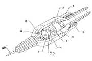
- FIG. 1is a perspective view of a fully assembled, automatic drainage embodiment.
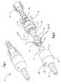
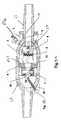
- FIG. 2is an exploded perspective view showing the components comprising this passive magnetic bladder-cycling valve.
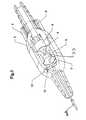
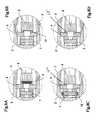
- FIG. 3is a cutaway of the assembly showing the valve in the closed configuration
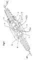
- FIG. 4is a cutaway of the assembly with the valve open.
- FIG. 5is a section view of the assembly showing the valve closed.
- FIGS. 6A and 6Bshows an added over-pressure safety release plug embodiment.
- FIG. 7Ais a section view of assembly with the valve open.
- FIG. 7Bis an enlarged view of an optional screw with magnet that can alter valve opening pressure.
- FIGS. 8A, 8 B, 8 C, and 8 Dshow embodiments of valve seal and valve seat combinations and useful configurations.
- FIGS. 9A, 9 B, 9 C and 9 Dshows a fluid pressure and flow time chart showing the invention system operation.
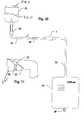
- FIG. 10illustrates the bladder cycler being used with a connected clinician's (or physician's) self-sealing sampling port on the inlet end and a hydrodynamically-balanced outlet downline to a fluid collection bag on the outlet end.
- FIG. 11is a side view of a patient's leg with the invention strapped to it.
- FIG. 1is a perspective view of the fully assembled bladder cycling passive magnetic valve invention 1 .
- FIG. 2is an exploded view of the internal components of the invention 1 of FIG. 1 . Referring to FIGS. 1 and 2, this exploded view shows the key components comprising the assembly.
- the inlet end, or upper non-magnetic housing 2has female socket end 2 . 2 which mates with the male prong end 3 . 2 of outlet end, or lower housing non-magnetic 3 , with a water-tight and air-tight bond.
- a moving magnetic valve member 8is magnetically attracted in the direction of valve-port wall 4 where the resilient valve seal 9 contacts the valve seat at the outlet end of valve insert orifice 4 .
- the moving magnetic valve member 8is attracted magnetically to the valve-port wall 4 due to the fixed upstream magnetic member 7 .
- Inwardly protruding rails 3 . 6 in lower housing 3form an internal chamber for allowing the moving magnet valve 8 to slide back and forth.
- Fixed magnetic member 7is held in place by prongs 4 . 6 extending from wall 4 having openings/slots 4 . 3 therebetween.
- the openings/slots 4 . 3are large enough to allow for fluid flow around the fixed magnetic member 7 .
- Magnetic attractioncan be provided by composition of either or both the moving valve member and the upstream magnetic member.
- the magnetic valve member 8 and the upstream magnetic member 7both are inert, ceramic permanent magnets having high magnetic field saturation and high coercive magnetic force, and the valve-port wall 4 is non-magnetic. Opposite, attracting poles of each magnetic member 7 , 8 are facing each other in the fully operational valve.
- a fully assembled “dummy” valvecan be substituted with like magnetic poles facing each other, thus making a non-closing, constantly open, “placebo” unit.
- a preferred embodiment of the moveable magnet member 8was measured at approximately 130 milligauss(mG) at a distance of approximately 7 millimeters(mm) from the sensing coil of a DC Magnetometer.
- the fixed magnet member 7had a measurement of approximately 40 mG. Both magnet members 7 , 8 were approximately 0.375 inches in diameter.
- the pressure needed to open the valve member 8 away from its seatwas adjusted to be approximately 0.1 ounces per square feet(ounces/sq.ft), which correlated to approximately 15 cm height of H2O, in the catheter line.
- channel ridges 17 at the inside periphery of non-magnetic housing 3provide fluid passage linearly between them from side-to-side of first the magnetic base member 7 and then the magnetic valve member 8 .
- stopper shoulders 18are provided to arrest travel of the magnetic valve member 8 at a select distance of travel away from valve-port wall 3 . 4 .
- valve-port wallis provided with a valve-seat ridge 9 for reduction of valve-seat area to reduce area for accumulation of particulates in fluid passing through the system and for providing a relatively smaller surface for tightly seating into the moving valve member 8 .
- Moving valve member 8can move in an interior chamber within housing section 3 in both directions as shown by arrows M 1 and M 2 .
- a resilient non-magnetic valve surface 9can be provided for increased seating pressure and for selectively decreased magnetic attraction in the direction of the valve-port wall 19 . 2 .
- Alternative valve seat/seal configurationsare illustrated in FIGS. 8B, 8 C, and 8 D.
- FIG. 8Cthe low-durometer, soft, resilient seal 4 .
- an FDA-approved materialeg: silicone
- silicone resilient O-ring 15can be either bonded or inserted in the wall member of valve seat insert 4 to provide a low-pressure fluid seal against the face of the moving magnetic material 8 .
- inside corners of magnetic valve member 8inside corner edges of housing inlets 2 , inside corner edges of housing outlets 3 and all other corners possible can be rounded to facilitate flow through the system and to prevent accumulation of particulates in fluid passing through the system.
- Outside surfaces of inlet housing 2 and outside surface of outlet housing 3also can be rounded to prevent scraping action that would tend to accumulate particles at the outside and decrease cleanliness.
- the inside corners of the housing outletscan be angled from the basically symmetrical barbed inlet and outlet connectors 11 which can be selectively tapered, ribbed or otherwise designed to receive and to hold medical tubing.
- an optional soft elastic plug 12may be inserted into a vent line 13 . 2 / 13 . 4 to serve as a safety pressure release valve (perhaps if blockage in the system caused urine pressure in the bladder to build up past some potentially hazardous number like 80-120 cm/H2O column) which would pop out to avoid renal or other physiological damage. Details are shown in FIGS. 6A and 6B. In addition, this feature could allow medicine to be injected into the urinary tract on the bladder side, if desired, to control or prevent infection.
- FIG. 6Ahas a blunt edge plug 12 . 2 , which fits within a uniform diameter vent line 13 . 2
- an alternative version FIG. 6Bhas an expanded tip 13 . 4 which fits within and catches against an interior surface about narrowing vent line 13 . 4
- another (threaded) hole 2 . 5could be used to position a screw 29 /magnet 30 mechanism so as to position a third permanent magnet 30 in close proximity to the back of the “fixed” magnet member 7 , in order to alter the net magnetic field strength and thus control the valve opening pressure.
- the present magnet-holding insert 4can be molded in a soft plastic material in order to make a good seal against the moving magnet face on component 8 .
- the South Pole of the moving magnet 8faces the valve seat 19 at its left. This South Pole is attracted to the North Pole of the fixed magnet 7 behind the seat 19 to its left.
- the manual external rotational adjustment of externally adjustable screw 30controls the magnet 30 South pole separation from the magnet 7 South pole which would allow a significant degree of valve pressure opening adjustment, or variable pressure setting, which can be desirable in certain situations.
- the closer magnet 30 is to magnet 7the less net field strength there is to attract magnet 8 .
- magnet 30has less effect in canceling some of the strength of magnet 7 , and the opening pressure is higher.
- bladder detrusor muscle atonyhas occurred, or when therapeutic bladder retraining is called for, lowered position of magnet 30 toward magnet 7 (screwing the magnet 30 in closer), or graduated pressure settings can provide substantial additional benefits.
- the opening pressure settingcan be determined by the insert dimensions (assuming a consistent magnet gauss reading) and each unit can acquire a fixed pressure value during the manufacturing process. While the normal opening range is approximately 15 to approximately 30 cm/H2O, individual units can be made to operate at higher or lower pressures, within practical limits.
- Head pressure to open the valvecan be decreased by pressing the button inwardly and sliding the magnetic base member in the direction of the housing inlet.
- the valvecan be totally released without any magnetic pressure to hold the valve shut when the magnetic base is slid to the extreme housing-inlet end of travel of the button stem in the stem channels.
- Closing pressure of the valveis increased by sliding the magnetic base member in a downstream direction toward the housing outlet.
- a siphon air vent micro-port filter 6 and cover 5can be provided to effect a very low-pressure siphon, suction, or negative pressure from fluid passing through the housing outlets 11 . 2 and down the drain line 22 into the collection bag 27 .
- the filter material within filter 6either woven or non-woven attaches by an adhesive and is packed around the housing vent hole 10 . This feature of the invention assists in holding the valve 8 open until all the fluid is emptied out of the system as well as allowing the system tubing to drain clean and dry, thus preventing moist surfaces within the system for potential bacterial growth.
- the vent filter 6allows for a stream of air bubbles to enter line 22 to aid in allowing complete drainage of all fluid through line 22 , since in a gravity directed flow system an upper located vent enhances fluid flow therethrough.
- the vent valve 10can be positioned at the outside periphery of a valve-port wall 3 . 6 and the vent aperture 10 can be positioned in the outside periphery of an outlet housing member 3 that is created during plastic injection molding process or in the construction assembly process.
- the assemblycan be either glued, chemically welded, ultrasonically welded, or press-fit snugly enough to remain assembled without glue.
- the magnetic base member 7can be either glued or otherwise fixed in seats 4 . 6 in a position at a select distance from the valve-port wall (seat) to achieve a pre-determined pressure requirement for opening of the valve 8 in opposition to magnetic attraction of the base member 7 and the valve 8 .
- the magnetic base member 7 in FIG. 2can be moved by an automatic, but very weak, drainage spring or other weakly resilient member.
- this inventionprovides some features of the controllable embodiment at a lower cost of construction.
- a springy material in this working relationshipfunctions in the opposite direction as springs used to close valves in prior-art practices. It decreases rather than increases opening pressure of the valve when pressure in the bladder is low from being partially emptied. This configuration would require a very careful design and implementation in order to balance the static and dynamic forces precisely for operation, both in the opening pressure and to assure valve closing, sealing without leaking during urine pressure buildup to the opening threshold.
- this diagramtraces out the cycler invention use method as the key component of a hydrodynamically-balanced cyclic urinary drainage system.
- the human (or animal) bladder 23 and bladder contents 23 . 5 with its two ureter inputshas its attached urethra 24 invaded by an indwelling catheter (such as a balloon-anchored Foley type) 25 .
- this cathetercan be connected to a clinician's (physician's) sampling port 26 , from which a urine sample can be drawn by either a conventional syringe needle or by a safety plastic canula probe.
- valve 8is in a closed position to inhibit fluid flow therethrough.
- Arrow 14 A of FIG. 3shows the direction of fluid flow which stops by closed seated valve 8 .
- a patientcan use their bladder detrusor muscle 23 . 7 about the bladder 23 to cause a small amount of pressure in the catheter line 25 , 22 to cause the valve 8 in cycler 1 to pass to an open position(in the direction of arrow M 1 ) to allow fluid flow therethrough.
- Arrows 14 B and 14 C of FIG. 4show fluid passing through cycler 1 .
- Fluid running down line 22assists in maintaining the valve 8 in an open position by causing a hydrodynamic pulling on the valve 8 so that all fluid flow passes therethrough.
- the hydrodynamic pulling on the valve 8causes by the fluid flowing through line 22 is stronger than the attractive forces between magnet valve 8 and member 7 .
- no further hydrodynamic forces exist to keep the valve 8 in the open positionso now valve 8 is free to move in the direction of arrow M 2 to a closed position since the attractive power of the magnets 7 and 8 causes valve 8 to move in the direction of arrow M 2 .
- the subject invention valve 8does not function in an equivalent manner.
- the larger the opening of the magnetic valve 8the less the pull(magnetic attraction with member 8 ) exists to close the valve 8 .
- the greater the opening in a valvethe greater the resistance is from the compressed spring to cause a closure of the valve.
- a patient exerting fluid pressure to open a spring biased-backed valvehas greater resistance that occurs as they try to increase urination pressure.
- magnetic valve 8more pressure from the bladder causes less resistance against the valve 8 , and helps fluid flow therethrough.
- spring biased-backed valveshave been known to cause a premature closing in a catheter line which can cause any of the medical problems referred to in the background section of the invention.
- the subject invention magnetic valve 8does not prematurely close since the hydrodynamic gravity enhanced pulling of fluid downline is enough to overcome the magnetic attraction to keep the valve open. When downline fluid flow ceases, the hydrodynamic gravity enhanced pulling of fluid ceases and the magnetic attraction is enough to close off valve 8 .
- the subject inventionallows a person to use their bladder detrusor muscle to cause pressure selectively turn on and complete urination emptying cycle of the contents of the bladder while wearing a catheter.
- the cycler 1can be an alternative to using dangerous clamps on a catheter line, since clamps left on a catheter line for extended periods of time can be hazardous to a patient's life.
- the cycler 1allows for a fluid samples to accumulate about port 26 so that an adequate sample can be retrieved when needed.
- the cycler invention 1 with magnetic moving valve 8can be connected between the sampling port 26 and the specially-sized downline tubing 22 , thus forming a hydrodynamically-balanced drainage system, terminated by the collection bag 27 and its clamped-off emptying tube 28 .
- a preferred embodimentincorporates the connections from the catheter be made as shown, and that the downline from the outlet end of the bladder cycler valve consist of approximately 0.1875 inch inside diameter tubing, preferably of polyethylene construction. The surface tension of the watery urine fluid 23 .
- the pressure needed to open the valve member 8 away from its seatwas adjusted to be approximately 0.1 ounces per square feet(ounces/sq.ft), which correlated to approximately 15 cm height of H2O, in the catheter line.
- a leg strap 20can be provided about a human leg 20 . 5 with a swivel connection 21 that allows the bladder cycler invention 1 to be positioned when desired at a downward angle with respect to a leg 20 . 5 to which it attached.
- Thisallows a catheter or outlet drainage tubing 22 to be positioned at a slant that provides downward flow of fluid that otherwise could remain in the system between drainage cycles.
- FIGS. 9A, 9 B, 9 C and 9 Dshow the time relationship between pressure buildup on a test stand, such as in the configuration diagrammed in FIGS. 10-11, the valve opening pressure drop, the initiation of fluid flow, the constant flow rate until the point of emptying, the valve closing again, and the cycling period to the next pressure fill and open sequence.
- This periodis normally approximately two to approximately four hours for the average adult, depending on amount of fluid beverages consumed, physical activity, and physiological factors such as bladder size, general health, pressure sensitivity, and the like.
- FIG. 9Athe commencement of urine flow is indicated at point 60 .
- the flowis quite consistent throughout the time period ending at point 61 , about 60 seconds.
- the flow charted from point 62 to 63represents another bladder emptying cycle.
- FIG. 9Billustrates the bladder pressure buildup cycle from 17 cm of water column pressure at point 70 to the valve opening threshold pressure of 21 cm at point 71 , dropping to zero at point 72 .
- the chartstops and a new partial cycle from point 74 at 16 cm of H2O to the opening point 75 at 22 cm of H2O.
- FIGS. 9C and 9Dshows charts that indicate that the flow rates and urine volumes are in the “normal” range(e.g. approximately 250 cc over 60 minutes.
- a manual override embodimentcan allow for selectively keeping valve 8 in an open position.
- an extra outside magnet 50can be positioned adjacent filter 6 to have South pole S, that attracts North pole N, of moving valve 8 in an open position.
- the manual override of the valvecan occur by selective distancing of an externally positioned magnetic 50 from the valve 8 that is attracted to it.
- the overridegives flexibility of pressure adjustment and provides the opportunity of assuring full drainage when desired by either physician or the patient. This could manifest itself, in the event of excessive discharge of viscous matter or other mode of lumen blockage, as a welcome “safety” valve to relieve fluid pressure buildup in the line and system upstream from the cycler 1 .
Landscapes
- Engineering & Computer Science (AREA)
- Health & Medical Sciences (AREA)
- General Engineering & Computer Science (AREA)
- Life Sciences & Earth Sciences (AREA)
- Hematology (AREA)
- Mechanical Engineering (AREA)
- Biomedical Technology (AREA)
- Heart & Thoracic Surgery (AREA)
- Anesthesiology (AREA)
- Animal Behavior & Ethology (AREA)
- General Health & Medical Sciences (AREA)
- Public Health (AREA)
- Veterinary Medicine (AREA)
- Pulmonology (AREA)
- Biophysics (AREA)
- Physics & Mathematics (AREA)
- Fluid Mechanics (AREA)
- Vascular Medicine (AREA)
- External Artificial Organs (AREA)
Abstract
Description
Claims (13)
Priority Applications (16)
| Application Number | Priority Date | Filing Date | Title |
|---|---|---|---|
| US10/010,534US6673051B2 (en) | 2001-04-02 | 2001-12-07 | Magnetic valve bladder cycler drainage system and use method with urinary catheters |
| US10/113,036US6855126B2 (en) | 2001-04-02 | 2002-04-01 | Conformable balloonless catheter |
| PCT/IB2002/002743WO2002087409A2 (en) | 2001-04-02 | 2002-04-01 | Conformable balloonless catheter |
| DE60239638TDE60239638D1 (en) | 2001-04-02 | 2002-04-01 | Magnetic shuttle valve for catheters |
| EP02755398AEP1383557B1 (en) | 2001-04-02 | 2002-04-01 | Conformable balloonless catheter |
| EP05077381AEP1645304B8 (en) | 2001-04-02 | 2002-04-01 | Magnetic cycler valve for catheters |
| DE60226719TDE60226719D1 (en) | 2001-04-02 | 2002-04-01 | ADJUSTABLE BALLOON FREE CATHEDRAL |
| AT02755398TATE395939T1 (en) | 2001-04-02 | 2002-04-01 | ADJUSTABLE BALLOONLESS CATHEDER |
| CNB028100336ACN1318105C (en) | 2001-04-02 | 2002-04-01 | Compliant Balloonless Catheter |
| AT05077381TATE503520T1 (en) | 2001-04-02 | 2002-04-01 | MAGNETIC EXCHANGE VALVE FOR CATHETER |
| AU2002321685AAU2002321685A1 (en) | 2001-04-02 | 2002-04-01 | Conformable balloonless catheter |
| PCT/IB2002/002266WO2002078765A2 (en) | 2001-04-02 | 2002-04-02 | Programmable flexible-tube flow regulator and use methods |
| US10/114,792US20020139419A1 (en) | 2001-04-02 | 2002-04-02 | Programmable flexible-tube flow regulator and use methods |
| EP02735855AEP1383570A4 (en) | 2001-04-02 | 2002-04-02 | Programmable flexible-tube flow regulator and use methods |
| AU2002309175AAU2002309175A1 (en) | 2001-04-02 | 2002-04-02 | Programmable flexible-tube flow regulator and use methods |
| MXPA03009072AMXPA03009072A (en) | 2001-04-02 | 2003-10-02 | Magnetic valve bladder cycler drainage system and use method with urinary catheters. |
Applications Claiming Priority (4)
| Application Number | Priority Date | Filing Date | Title |
|---|---|---|---|
| US28076701P | 2001-04-02 | 2001-04-02 | |
| US28076801P | 2001-04-02 | 2001-04-02 | |
| US32460101P | 2001-09-25 | 2001-09-25 | |
| US10/010,534US6673051B2 (en) | 2001-04-02 | 2001-12-07 | Magnetic valve bladder cycler drainage system and use method with urinary catheters |
Related Child Applications (2)
| Application Number | Title | Priority Date | Filing Date |
|---|---|---|---|
| US10/113,036Continuation-In-PartUS6855126B2 (en) | 2001-04-02 | 2002-04-01 | Conformable balloonless catheter |
| US10/114,792Continuation-In-PartUS20020139419A1 (en) | 2001-04-02 | 2002-04-02 | Programmable flexible-tube flow regulator and use methods |
Publications (2)
| Publication Number | Publication Date |
|---|---|
| US20020143318A1 US20020143318A1 (en) | 2002-10-03 |
| US6673051B2true US6673051B2 (en) | 2004-01-06 |
Family
ID=27486018
Family Applications (1)
| Application Number | Title | Priority Date | Filing Date |
|---|---|---|---|
| US10/010,534Expired - LifetimeUS6673051B2 (en) | 2001-04-02 | 2001-12-07 | Magnetic valve bladder cycler drainage system and use method with urinary catheters |
Country Status (2)
| Country | Link |
|---|---|
| US (1) | US6673051B2 (en) |
| MX (1) | MXPA03009072A (en) |
Cited By (23)
| Publication number | Priority date | Publication date | Assignee | Title |
|---|---|---|---|---|
| US20050154357A1 (en)* | 2004-01-13 | 2005-07-14 | Pinel Lloyd J. | Controlled gastric bolus feeding device |
| EP1645304A1 (en) | 2001-04-02 | 2006-04-12 | The Hook Research Foundation | Magnetic cycler valve for catheters |
| US20060095019A1 (en)* | 2004-11-02 | 2006-05-04 | Dikeman W C | Urinary catheter |
| US20060271019A1 (en)* | 2004-10-15 | 2006-11-30 | The Regents Of The University Of California | Drainage system |
| US20070010798A1 (en)* | 2004-04-02 | 2007-01-11 | The Regents Of The University Of California | Device and systems for the intermittent drainage of urine and other biological fluids |
| US20080281284A1 (en)* | 2007-05-08 | 2008-11-13 | Garfield Michael H | Fluid collection system |
| WO2008144622A1 (en)* | 2007-05-17 | 2008-11-27 | University Of South Florida | Bladder drainage aid |
| US20090013797A1 (en)* | 2007-07-13 | 2009-01-15 | The Coca-Cola Company | Magnetic flow sensor |
| US20090221933A1 (en)* | 2005-07-14 | 2009-09-03 | C.R. Bard, Inc. | Intra-abdominal pressure monitoring system |
| US20100094173A1 (en)* | 2007-03-16 | 2010-04-15 | Denton Marshall T | Pressure control for catheter drain tubing |
| US20100249663A1 (en)* | 2007-10-23 | 2010-09-30 | C.R. Bard, Inc. | Continuous intra-abdominal pressure monitoring system |
| US8177772B2 (en) | 2005-09-26 | 2012-05-15 | C. R. Bard, Inc. | Catheter connection systems |
| US20120172819A1 (en)* | 2011-01-03 | 2012-07-05 | Manuel Dugrot | Magnetically sealed intravenous access valve |
| US20120286185A1 (en)* | 2011-05-11 | 2012-11-15 | Spolski Kevin J | Valve for Regulating the Flow of A Liquid |
| US8337475B2 (en) | 2004-10-12 | 2012-12-25 | C. R. Bard, Inc. | Corporeal drainage system |
| US8636721B2 (en) | 2003-11-20 | 2014-01-28 | Henry M. Jackson Foundation For The Advancement Of Military Medicine, Inc. | Portable hand pump for evacuation of fluids |
| US9320882B2 (en) | 2013-01-16 | 2016-04-26 | Infinity Medical Engineering, Llc | Pressure controlled magnetic valve for a catheter |
| US9763762B2 (en) | 2013-09-25 | 2017-09-19 | Medtronic, Inc. | Implantable urinary tract valve |
| US11344318B2 (en) | 2016-07-18 | 2022-05-31 | Merit Medical Systems, Inc. | Inflatable radial artery compression device |
| US11865270B2 (en) | 2020-01-16 | 2024-01-09 | Starling Medical, Inc. | Bodily fluid management system |
| US20250003520A1 (en)* | 2023-06-28 | 2025-01-02 | Longfian Scitech Co., Ltd. | Magnet-driven fire damper for oxygenerator |
| US12419732B1 (en) | 2024-08-22 | 2025-09-23 | David E. Flinchbaugh | Bladder management device and method |
| US12426864B2 (en) | 2021-06-18 | 2025-09-30 | Merit Medical Systems, Inc. | Hemostasis devices and methods of use |
Families Citing this family (12)
| Publication number | Priority date | Publication date | Assignee | Title |
|---|---|---|---|---|
| JP2005531392A (en)* | 2003-04-22 | 2005-10-20 | ザ・フック・リサーチ・ファウンデーション | Cycler drainage system for magnetic valve type bladder and method of use with urinary catheter |
| CA2668792C (en)* | 2008-06-30 | 2017-08-01 | Tyco Healthcare Group Lp | Valve assembly including a dissolvable valve member |
| US8128608B2 (en)* | 2008-07-03 | 2012-03-06 | Claude Thevenin | Automatic pubic area cleaning system |
| US8801697B2 (en)* | 2009-04-20 | 2014-08-12 | Cheiron Japan Co. | Urination control device |
| DE102011003007A1 (en)* | 2011-01-21 | 2012-07-26 | Mgb Endoskopische Geräte Gmbh Berlin | Printed circuit board with overpressure valve, insufflator |
| US20120286187A1 (en)* | 2011-05-11 | 2012-11-15 | Spolski Kevin J | Valve for Regulating the Flow of A Liquid |
| CN106170653A (en)* | 2014-03-06 | 2016-11-30 | 拜耳医药保健有限公司 | Magnetic medical connector and the fluid delivery system including magnetic medical connector |
| CN103982687B (en)* | 2014-05-16 | 2016-02-10 | 游建龙 | Restriction fills cylinder valve |
| DK3572120T3 (en)* | 2015-01-22 | 2024-07-22 | Ecp Entw Mbh | Catheter device containing a valve for controlling a fluid flow through a catheter |
| US11439522B2 (en)* | 2020-08-25 | 2022-09-13 | Fillauer Companies, Inc. | Valve assembly for a prosthetic socket |
| CN113648476B (en)* | 2021-08-10 | 2024-01-16 | 李冰冰 | Gynecological tumor cleaning device with hierarchical flushing structure |
| CN119792692B (en)* | 2025-01-06 | 2025-09-30 | 中国人民解放军陆军军医大学第一附属医院 | A urinary catheter device |
Citations (13)
| Publication number | Priority date | Publication date | Assignee | Title |
|---|---|---|---|---|
| US3642004A (en)* | 1970-01-05 | 1972-02-15 | Life Support Equipment Corp | Urethral valve |
| US3777737A (en)* | 1971-01-04 | 1973-12-11 | Investors In Ventures Inc | Method and device for reversibly interrupting fluid flow in a living being |
| US4230102A (en) | 1977-04-25 | 1980-10-28 | Astra-Sjuco Ab | Device for the training of a urine bladder |
| US4424058A (en) | 1981-11-23 | 1984-01-03 | Parsons Robert L | Drainage control method and apparatus |
| US4865588A (en)* | 1988-08-31 | 1989-09-12 | Medical Inventor's Corp. | Magnetic bladder cycler and use method |
| US4869457A (en)* | 1986-09-10 | 1989-09-26 | Ewerloef Goeran | Arrangement for controlling and regulating a liquid flowing through a line |
| US4994020A (en)* | 1989-07-21 | 1991-02-19 | American Medical Systems, Inc. | Implantable artificial sphincter system |
| US5011472A (en)* | 1988-09-06 | 1991-04-30 | Brown University Research Foundation | Implantable delivery system for biological factors |
| US5030199A (en)* | 1989-12-11 | 1991-07-09 | Medical Engineering Corporation | Female incontinence control device with magnetically operable valve and method |
| US5041092A (en)* | 1989-08-29 | 1991-08-20 | Medical Engineering Corporation | Urethral indwelling catheter with magnetically controlled drainage valve and method |
| US5445613A (en)* | 1993-07-16 | 1995-08-29 | Rocky Mountain Research, Inc. | Condition detection system and clamp |
| US6066088A (en)* | 1998-07-13 | 2000-05-23 | Phillip Davis Inventions, Inc. | Intraurethral magnetic valve |
| US6106503A (en)* | 1997-04-24 | 2000-08-22 | Caremed Medical Produkte Ag | Catheter valve |
- 2001
- 2001-12-07USUS10/010,534patent/US6673051B2/ennot_activeExpired - Lifetime
- 2003
- 2003-10-02MXMXPA03009072Apatent/MXPA03009072A/enactiveIP Right Grant
Patent Citations (14)
| Publication number | Priority date | Publication date | Assignee | Title |
|---|---|---|---|---|
| US3642004A (en)* | 1970-01-05 | 1972-02-15 | Life Support Equipment Corp | Urethral valve |
| US3777737A (en)* | 1971-01-04 | 1973-12-11 | Investors In Ventures Inc | Method and device for reversibly interrupting fluid flow in a living being |
| US4230102A (en) | 1977-04-25 | 1980-10-28 | Astra-Sjuco Ab | Device for the training of a urine bladder |
| US4424058A (en) | 1981-11-23 | 1984-01-03 | Parsons Robert L | Drainage control method and apparatus |
| US4869457A (en)* | 1986-09-10 | 1989-09-26 | Ewerloef Goeran | Arrangement for controlling and regulating a liquid flowing through a line |
| US5114412A (en) | 1988-08-31 | 1992-05-19 | Flinchbaugh David E | Magnetic bladder cycler |
| US4865588A (en)* | 1988-08-31 | 1989-09-12 | Medical Inventor's Corp. | Magnetic bladder cycler and use method |
| US5011472A (en)* | 1988-09-06 | 1991-04-30 | Brown University Research Foundation | Implantable delivery system for biological factors |
| US4994020A (en)* | 1989-07-21 | 1991-02-19 | American Medical Systems, Inc. | Implantable artificial sphincter system |
| US5041092A (en)* | 1989-08-29 | 1991-08-20 | Medical Engineering Corporation | Urethral indwelling catheter with magnetically controlled drainage valve and method |
| US5030199A (en)* | 1989-12-11 | 1991-07-09 | Medical Engineering Corporation | Female incontinence control device with magnetically operable valve and method |
| US5445613A (en)* | 1993-07-16 | 1995-08-29 | Rocky Mountain Research, Inc. | Condition detection system and clamp |
| US6106503A (en)* | 1997-04-24 | 2000-08-22 | Caremed Medical Produkte Ag | Catheter valve |
| US6066088A (en)* | 1998-07-13 | 2000-05-23 | Phillip Davis Inventions, Inc. | Intraurethral magnetic valve |
Cited By (42)
| Publication number | Priority date | Publication date | Assignee | Title |
|---|---|---|---|---|
| EP1645304A1 (en) | 2001-04-02 | 2006-04-12 | The Hook Research Foundation | Magnetic cycler valve for catheters |
| US10213532B2 (en) | 2003-11-20 | 2019-02-26 | The Henry M. Jackson Foundation For The Advancement Of Military Medicine, Inc. | Portable hand pump for evacuation of fluids |
| US9393353B2 (en) | 2003-11-20 | 2016-07-19 | The Henry M. Jackson Foundation For The Advancement Of Military Medicine, Inc. | Portable hand pump for evacuation of fluids |
| US9907887B2 (en) | 2003-11-20 | 2018-03-06 | The Henry M. Jackson Foundation For The Advancement Of Military Medicine, Inc. | Portable hand pump for evacuation of fluids |
| US8636721B2 (en) | 2003-11-20 | 2014-01-28 | Henry M. Jackson Foundation For The Advancement Of Military Medicine, Inc. | Portable hand pump for evacuation of fluids |
| US20050154357A1 (en)* | 2004-01-13 | 2005-07-14 | Pinel Lloyd J. | Controlled gastric bolus feeding device |
| US7794436B2 (en)* | 2004-01-13 | 2010-09-14 | Lloyd Jay Pinel | Controlled gastric bolus feeding device |
| US20070010798A1 (en)* | 2004-04-02 | 2007-01-11 | The Regents Of The University Of California | Device and systems for the intermittent drainage of urine and other biological fluids |
| US9913935B2 (en) | 2004-10-12 | 2018-03-13 | C. R. Bard, Inc. | Corporeal drainage system |
| US10946123B2 (en) | 2004-10-12 | 2021-03-16 | Merit Medical Systems, Inc. | Corporeal drainage system |
| US9295764B2 (en) | 2004-10-12 | 2016-03-29 | C. R. Bard, Inc. | Corporeal drainage system |
| US8337475B2 (en) | 2004-10-12 | 2012-12-25 | C. R. Bard, Inc. | Corporeal drainage system |
| US8814839B2 (en) | 2004-10-12 | 2014-08-26 | C. R. Bard, Inc. | Corporeal drainage system |
| US20060271019A1 (en)* | 2004-10-15 | 2006-11-30 | The Regents Of The University Of California | Drainage system |
| US20060095019A1 (en)* | 2004-11-02 | 2006-05-04 | Dikeman W C | Urinary catheter |
| US20090221933A1 (en)* | 2005-07-14 | 2009-09-03 | C.R. Bard, Inc. | Intra-abdominal pressure monitoring system |
| US8337411B2 (en)* | 2005-07-14 | 2012-12-25 | C. R. Bard, Inc. | Intra-abdominal pressure monitoring system |
| US8177772B2 (en) | 2005-09-26 | 2012-05-15 | C. R. Bard, Inc. | Catheter connection systems |
| US8235971B2 (en) | 2005-09-26 | 2012-08-07 | C. R. Bard, Inc. | Catheter connection systems |
| US20100094173A1 (en)* | 2007-03-16 | 2010-04-15 | Denton Marshall T | Pressure control for catheter drain tubing |
| US20080281284A1 (en)* | 2007-05-08 | 2008-11-13 | Garfield Michael H | Fluid collection system |
| US20100063465A1 (en)* | 2007-05-17 | 2010-03-11 | University Of South Florida | Bladder drainage aid |
| WO2008144622A1 (en)* | 2007-05-17 | 2008-11-27 | University Of South Florida | Bladder drainage aid |
| US8579873B2 (en) | 2007-05-17 | 2013-11-12 | University Of South Florida | Bladder drainage aid |
| US7584657B2 (en)* | 2007-07-13 | 2009-09-08 | The Coca-Cola Company | Magnetic flow sensor |
| US20090013797A1 (en)* | 2007-07-13 | 2009-01-15 | The Coca-Cola Company | Magnetic flow sensor |
| US8535237B2 (en) | 2007-10-23 | 2013-09-17 | C. R. Bard, Inc. | Continuous intra-abdominal pressure monitoring system |
| US20100249663A1 (en)* | 2007-10-23 | 2010-09-30 | C.R. Bard, Inc. | Continuous intra-abdominal pressure monitoring system |
| US8460253B2 (en)* | 2011-01-03 | 2013-06-11 | Manuel Dugrot | Magnetically sealed intravenous access valve |
| US20120172819A1 (en)* | 2011-01-03 | 2012-07-05 | Manuel Dugrot | Magnetically sealed intravenous access valve |
| US8684331B2 (en)* | 2011-05-11 | 2014-04-01 | Bioflo, Llc | Valve for regulating the flow of a liquid |
| US20120286185A1 (en)* | 2011-05-11 | 2012-11-15 | Spolski Kevin J | Valve for Regulating the Flow of A Liquid |
| US11802627B2 (en) | 2011-05-11 | 2023-10-31 | Bioflo, Llc | Valve for regulating the flow of a liquid |
| US9320882B2 (en) | 2013-01-16 | 2016-04-26 | Infinity Medical Engineering, Llc | Pressure controlled magnetic valve for a catheter |
| US10575935B2 (en) | 2013-09-25 | 2020-03-03 | Medtronic, Inc. | Implantable urinary tract valve |
| US9763762B2 (en) | 2013-09-25 | 2017-09-19 | Medtronic, Inc. | Implantable urinary tract valve |
| US11344318B2 (en) | 2016-07-18 | 2022-05-31 | Merit Medical Systems, Inc. | Inflatable radial artery compression device |
| US11865270B2 (en) | 2020-01-16 | 2024-01-09 | Starling Medical, Inc. | Bodily fluid management system |
| US12426864B2 (en) | 2021-06-18 | 2025-09-30 | Merit Medical Systems, Inc. | Hemostasis devices and methods of use |
| US20250003520A1 (en)* | 2023-06-28 | 2025-01-02 | Longfian Scitech Co., Ltd. | Magnet-driven fire damper for oxygenerator |
| US12320442B2 (en)* | 2023-06-28 | 2025-06-03 | Longfian Scitech Co., Ltd. | Magnet-driven fire damper for oxygenerator |
| US12419732B1 (en) | 2024-08-22 | 2025-09-23 | David E. Flinchbaugh | Bladder management device and method |
Also Published As
| Publication number | Publication date |
|---|---|
| US20020143318A1 (en) | 2002-10-03 |
| MXPA03009072A (en) | 2005-07-15 |
Similar Documents
| Publication | Publication Date | Title |
|---|---|---|
| US6673051B2 (en) | Magnetic valve bladder cycler drainage system and use method with urinary catheters | |
| CN114390910B (en) | Fluid collection assembly including sample port | |
| US20240342445A1 (en) | Catheter and click connector | |
| US6855126B2 (en) | Conformable balloonless catheter | |
| US4865588A (en) | Magnetic bladder cycler and use method | |
| US7025742B2 (en) | Internally powered CSF pump systems and methods | |
| US20070010798A1 (en) | Device and systems for the intermittent drainage of urine and other biological fluids | |
| US20180125697A1 (en) | Valve Assembly for Modifying Flow in a Catheter System | |
| US4337775A (en) | Catheter drainage and protection unit | |
| US20120316539A1 (en) | Catheter Clamp | |
| WO2004098686A1 (en) | Magnetic valve bladder cycler drainage system and use method with urinary catheters | |
| JP3234453U (en) | Backflow stopper to prevent backflow of urine | |
| AU2002227205B2 (en) | Magnetic valve bladder cycler drainage system and use method with urinary catheters | |
| US20120239006A1 (en) | External control valve for indwelling urethral catheters | |
| US12042420B2 (en) | Urine collection bag assembly | |
| KR102233114B1 (en) | Urine Bag | |
| US20250073419A1 (en) | Spring-Loaded Valve Urine Backflow Prevention Device and Method of Use | |
| IT202100000314U1 (en) | Valve with elastic membrane with central notch to be applied to a catheter for direct connection to a drainage tube | |
| JPS6080459A (en) | Drainage control method and apparatus | |
| CN88201971U (en) | Sleeve bag for urine |
Legal Events
| Date | Code | Title | Description |
|---|---|---|---|
| AS | Assignment | Owner name:HOOK RESEARCH FOUNDATION THE, PANAMA Free format text:ASSIGNMENT OF ASSIGNORS INTEREST;ASSIGNOR:FLINCHBAUGH, DAVID E.;REEL/FRAME:012383/0393 Effective date:20011205 | |
| AS | Assignment | Owner name:BLADDER MANAGEMENT SYSTEMS, LLC, FLORIDA Free format text:ASSIGNMENT OF ASSIGNORS INTEREST;ASSIGNOR:THE HOOK RESEARCH FOUNDATION;REEL/FRAME:019224/0604 Effective date:20070424 | |
| FPAY | Fee payment | Year of fee payment:4 | |
| AS | Assignment | Owner name:FLINCHBAUGH, DAVID E., DR., FLORIDA Free format text:ASSIGNMENT OF ASSIGNORS INTEREST;ASSIGNORS:GLOBAL MEDICAL RESEARCH LLC;BLADDER MANAGEMENT SYSTEMS LLC;REEL/FRAME:023574/0649 Effective date:20091130 | |
| REMI | Maintenance fee reminder mailed | ||
| FEPP | Fee payment procedure | Free format text:PETITION RELATED TO MAINTENANCE FEES FILED (ORIGINAL EVENT CODE: PMFP); ENTITY STATUS OF PATENT OWNER: SMALL ENTITY | |
| FEPP | Fee payment procedure | Free format text:PETITION RELATED TO MAINTENANCE FEES GRANTED (ORIGINAL EVENT CODE: PMFG); ENTITY STATUS OF PATENT OWNER: SMALL ENTITY | |
| LAPS | Lapse for failure to pay maintenance fees | ||
| REIN | Reinstatement after maintenance fee payment confirmed | ||
| FPAY | Fee payment | Year of fee payment:8 | |
| SULP | Surcharge for late payment | ||
| PRDP | Patent reinstated due to the acceptance of a late maintenance fee | Effective date:20120522 | |
| STCF | Information on status: patent grant | Free format text:PATENTED CASE | |
| REMI | Maintenance fee reminder mailed | ||
| FPAY | Fee payment | Year of fee payment:12 | |
| SULP | Surcharge for late payment | Year of fee payment:11 |