US6673049B2 - Injection device for injecting fluid - Google Patents
Injection device for injecting fluidDownload PDFInfo
- Publication number
- US6673049B2 US6673049B2US09/784,661US78466101AUS6673049B2US 6673049 B2US6673049 B2US 6673049B2US 78466101 AUS78466101 AUS 78466101AUS 6673049 B2US6673049 B2US 6673049B2
- Authority
- US
- United States
- Prior art keywords
- counter component
- injection device
- driven member
- component
- counter
- Prior art date
- Legal status (The legal status is an assumption and is not a legal conclusion. Google has not performed a legal analysis and makes no representation as to the accuracy of the status listed.)
- Expired - Fee Related, expires
Links
Images


Classifications
- A—HUMAN NECESSITIES
- A61—MEDICAL OR VETERINARY SCIENCE; HYGIENE
- A61M—DEVICES FOR INTRODUCING MEDIA INTO, OR ONTO, THE BODY; DEVICES FOR TRANSDUCING BODY MEDIA OR FOR TAKING MEDIA FROM THE BODY; DEVICES FOR PRODUCING OR ENDING SLEEP OR STUPOR
- A61M5/00—Devices for bringing media into the body in a subcutaneous, intra-vascular or intramuscular way; Accessories therefor, e.g. filling or cleaning devices, arm-rests
- A61M5/178—Syringes
- A61M5/31—Details
- A61M5/315—Pistons; Piston-rods; Guiding, blocking or restricting the movement of the rod or piston; Appliances on the rod for facilitating dosing ; Dosing mechanisms
- A61M5/31533—Dosing mechanisms, i.e. setting a dose
- A61M5/31545—Setting modes for dosing
- A61M5/31548—Mechanically operated dose setting member
- A61M5/3155—Mechanically operated dose setting member by rotational movement of dose setting member, e.g. during setting or filling of a syringe
- A61M5/31553—Mechanically operated dose setting member by rotational movement of dose setting member, e.g. during setting or filling of a syringe without axial movement of dose setting member
- A—HUMAN NECESSITIES
- A61—MEDICAL OR VETERINARY SCIENCE; HYGIENE
- A61M—DEVICES FOR INTRODUCING MEDIA INTO, OR ONTO, THE BODY; DEVICES FOR TRANSDUCING BODY MEDIA OR FOR TAKING MEDIA FROM THE BODY; DEVICES FOR PRODUCING OR ENDING SLEEP OR STUPOR
- A61M5/00—Devices for bringing media into the body in a subcutaneous, intra-vascular or intramuscular way; Accessories therefor, e.g. filling or cleaning devices, arm-rests
- A61M5/178—Syringes
- A61M5/24—Ampoule syringes, i.e. syringes with needle for use in combination with replaceable ampoules or carpules, e.g. automatic
- A—HUMAN NECESSITIES
- A61—MEDICAL OR VETERINARY SCIENCE; HYGIENE
- A61M—DEVICES FOR INTRODUCING MEDIA INTO, OR ONTO, THE BODY; DEVICES FOR TRANSDUCING BODY MEDIA OR FOR TAKING MEDIA FROM THE BODY; DEVICES FOR PRODUCING OR ENDING SLEEP OR STUPOR
- A61M5/00—Devices for bringing media into the body in a subcutaneous, intra-vascular or intramuscular way; Accessories therefor, e.g. filling or cleaning devices, arm-rests
- A61M5/178—Syringes
- A61M5/31—Details
- A61M5/315—Pistons; Piston-rods; Guiding, blocking or restricting the movement of the rod or piston; Appliances on the rod for facilitating dosing ; Dosing mechanisms
- A61M5/31501—Means for blocking or restricting the movement of the rod or piston
- A—HUMAN NECESSITIES
- A61—MEDICAL OR VETERINARY SCIENCE; HYGIENE
- A61M—DEVICES FOR INTRODUCING MEDIA INTO, OR ONTO, THE BODY; DEVICES FOR TRANSDUCING BODY MEDIA OR FOR TAKING MEDIA FROM THE BODY; DEVICES FOR PRODUCING OR ENDING SLEEP OR STUPOR
- A61M5/00—Devices for bringing media into the body in a subcutaneous, intra-vascular or intramuscular way; Accessories therefor, e.g. filling or cleaning devices, arm-rests
- A61M5/14—Infusion devices, e.g. infusing by gravity; Blood infusion; Accessories therefor
- A61M5/142—Pressure infusion, e.g. using pumps
- A61M5/145—Pressure infusion, e.g. using pumps using pressurised reservoirs, e.g. pressurised by means of pistons
- A61M5/1452—Pressure infusion, e.g. using pumps using pressurised reservoirs, e.g. pressurised by means of pistons pressurised by means of pistons
- A61M2005/14573—Pressure infusion, e.g. using pumps using pressurised reservoirs, e.g. pressurised by means of pistons pressurised by means of pistons with a replaceable reservoir for quick connection/disconnection with a driving system
- A—HUMAN NECESSITIES
- A61—MEDICAL OR VETERINARY SCIENCE; HYGIENE
- A61M—DEVICES FOR INTRODUCING MEDIA INTO, OR ONTO, THE BODY; DEVICES FOR TRANSDUCING BODY MEDIA OR FOR TAKING MEDIA FROM THE BODY; DEVICES FOR PRODUCING OR ENDING SLEEP OR STUPOR
- A61M5/00—Devices for bringing media into the body in a subcutaneous, intra-vascular or intramuscular way; Accessories therefor, e.g. filling or cleaning devices, arm-rests
- A61M5/178—Syringes
- A61M5/24—Ampoule syringes, i.e. syringes with needle for use in combination with replaceable ampoules or carpules, e.g. automatic
- A61M2005/2403—Ampoule inserted into the ampoule holder
- A61M2005/2407—Ampoule inserted into the ampoule holder from the rear
- A—HUMAN NECESSITIES
- A61—MEDICAL OR VETERINARY SCIENCE; HYGIENE
- A61M—DEVICES FOR INTRODUCING MEDIA INTO, OR ONTO, THE BODY; DEVICES FOR TRANSDUCING BODY MEDIA OR FOR TAKING MEDIA FROM THE BODY; DEVICES FOR PRODUCING OR ENDING SLEEP OR STUPOR
- A61M5/00—Devices for bringing media into the body in a subcutaneous, intra-vascular or intramuscular way; Accessories therefor, e.g. filling or cleaning devices, arm-rests
- A61M5/178—Syringes
- A61M5/24—Ampoule syringes, i.e. syringes with needle for use in combination with replaceable ampoules or carpules, e.g. automatic
- A61M2005/2485—Ampoule holder connected to rest of syringe
- A61M2005/2488—Ampoule holder connected to rest of syringe via rotation, e.g. threads or bayonet
- A—HUMAN NECESSITIES
- A61—MEDICAL OR VETERINARY SCIENCE; HYGIENE
- A61M—DEVICES FOR INTRODUCING MEDIA INTO, OR ONTO, THE BODY; DEVICES FOR TRANSDUCING BODY MEDIA OR FOR TAKING MEDIA FROM THE BODY; DEVICES FOR PRODUCING OR ENDING SLEEP OR STUPOR
- A61M5/00—Devices for bringing media into the body in a subcutaneous, intra-vascular or intramuscular way; Accessories therefor, e.g. filling or cleaning devices, arm-rests
- A61M5/178—Syringes
- A61M5/31—Details
- A61M5/315—Pistons; Piston-rods; Guiding, blocking or restricting the movement of the rod or piston; Appliances on the rod for facilitating dosing ; Dosing mechanisms
- A61M5/31525—Dosing
- A—HUMAN NECESSITIES
- A61—MEDICAL OR VETERINARY SCIENCE; HYGIENE
- A61M—DEVICES FOR INTRODUCING MEDIA INTO, OR ONTO, THE BODY; DEVICES FOR TRANSDUCING BODY MEDIA OR FOR TAKING MEDIA FROM THE BODY; DEVICES FOR PRODUCING OR ENDING SLEEP OR STUPOR
- A61M5/00—Devices for bringing media into the body in a subcutaneous, intra-vascular or intramuscular way; Accessories therefor, e.g. filling or cleaning devices, arm-rests
- A61M5/178—Syringes
- A61M5/31—Details
- A61M5/315—Pistons; Piston-rods; Guiding, blocking or restricting the movement of the rod or piston; Appliances on the rod for facilitating dosing ; Dosing mechanisms
- A61M5/31533—Dosing mechanisms, i.e. setting a dose
- A61M5/31535—Means improving security or handling thereof, e.g. blocking means, means preventing insufficient dosing, means allowing correction of overset dose
- A—HUMAN NECESSITIES
- A61—MEDICAL OR VETERINARY SCIENCE; HYGIENE
- A61M—DEVICES FOR INTRODUCING MEDIA INTO, OR ONTO, THE BODY; DEVICES FOR TRANSDUCING BODY MEDIA OR FOR TAKING MEDIA FROM THE BODY; DEVICES FOR PRODUCING OR ENDING SLEEP OR STUPOR
- A61M5/00—Devices for bringing media into the body in a subcutaneous, intra-vascular or intramuscular way; Accessories therefor, e.g. filling or cleaning devices, arm-rests
- A61M5/178—Syringes
- A61M5/31—Details
- A61M5/315—Pistons; Piston-rods; Guiding, blocking or restricting the movement of the rod or piston; Appliances on the rod for facilitating dosing ; Dosing mechanisms
- A61M5/31533—Dosing mechanisms, i.e. setting a dose
- A61M5/31545—Setting modes for dosing
- A61M5/31548—Mechanically operated dose setting member
- A61M5/31563—Mechanically operated dose setting member interacting with a displaceable stop member
- A—HUMAN NECESSITIES
- A61—MEDICAL OR VETERINARY SCIENCE; HYGIENE
- A61M—DEVICES FOR INTRODUCING MEDIA INTO, OR ONTO, THE BODY; DEVICES FOR TRANSDUCING BODY MEDIA OR FOR TAKING MEDIA FROM THE BODY; DEVICES FOR PRODUCING OR ENDING SLEEP OR STUPOR
- A61M5/00—Devices for bringing media into the body in a subcutaneous, intra-vascular or intramuscular way; Accessories therefor, e.g. filling or cleaning devices, arm-rests
- A61M5/178—Syringes
- A61M5/31—Details
- A61M5/315—Pistons; Piston-rods; Guiding, blocking or restricting the movement of the rod or piston; Appliances on the rod for facilitating dosing ; Dosing mechanisms
- A61M5/31565—Administration mechanisms, i.e. constructional features, modes of administering a dose
- A61M5/31576—Constructional features or modes of drive mechanisms for piston rods
- A61M5/31578—Constructional features or modes of drive mechanisms for piston rods based on axial translation, i.e. components directly operatively associated and axially moved with plunger rod
- A61M5/3158—Constructional features or modes of drive mechanisms for piston rods based on axial translation, i.e. components directly operatively associated and axially moved with plunger rod performed by axially moving actuator operated by user, e.g. an injection button
Definitions
- the present inventionrelates to an injection device for injecting fluid from a fluid container. It also relates to an actuator for such an injection device.
- Syringe-shaped injection devices for injecting fluidshave been known for some time. They contain a bushing-shaped main body which can be screwed together at approximately the centre and can be divided into two main sections:
- a distal section(facing away from the patient) containing the discharge mechanism and comprising at least one rod-shaped driven member having a structured surface (e.g. a screw rod), a hollow cylindrical counter component corresponding to the driven member, provided with a structured internal sleeve (e.g. a screw nut); and
- a proximal section(facing the patient) containing the fluid to be administered and a movable piston.
- a needle and a needle holderare attached, allowing the fluid to be discharged from the device; known needles of this type are for instance needles as described in WO95/01812.
- the connecting member between the proximal and the distal section of the main bodyis the driven member, shifting the piston by the required dose in proximal direction and discharging the fluid through the needle.
- the fluid to be injectedis not directly contained in the main body but in an ampoule or container, with the fluid being stored between a piercable membrane and a piston displaceable by sliding.
- the threaded nutis spread due to the release of the distal section from the proximal section of the main body, allowing the threaded rod to move freely without any conscious operation by the patient, with screwing together of both sections of the main body after replacement of the ampoule easily causing a premature unintentional discharge of fluid.
- thiscould also result in an incorrect dosing which, in case of certain medication, could be extremely hazardous to the patient's health.
- the injection devicecomprises a bushing-shaped main body 1 which can be divided into a rear (distal) section 3 containing the tubular actuating device or discharge mechanism 7 and a front (proximal) section 2 containing a replaceable ampoule 4 and a piston 5 .
- a needle 6with its distal end connected to the fluid to be administered can be screwed to the proximal end of the main body 1 .
- the actuating device 7comprises a control button 8 , a threaded rod 9 with a flange 19 , a guide member 24 and a driving member 11 .
- the tubular driving member 11is rigidly connected to the control button 8 to prevent twisting. At the proximal end, the driving member 11 surrounds two threaded flanges 27 , 27 ′ engaging in the thread of the threaded rod 9 .
- FIG. 18shows that the threaded rod 9 comprises two level surfaces 12 , 12 ′ and apart from that is of a circular cross section, with the circular surfaces 13 , 13 ′ being threaded.
- the guide member 24is rigidly connected to the distal section 3 of the main body 1 , thus preventing rotation or axial movement and is positioned in front of the driving member 11 .
- the aperture in the guide member 24through which the threaded rod 9 passes (FIG. 19) is of the same cross section as the threaded rod 9 —although enlarged by certain tolerances.
- the threaded rod 9can be shifted through the opening of the guide member in axial direction. A rotational movement of the threaded rod 9 is therefore not possible as the guide member 24 does not allow this.
- the control button 8may be moved in axial direction or may be rotated. Where the control button is activated by being pushed in proximal direction, it will simultaneously shift the driving member 11 until its front face 14 pushes against the rear face 14 ′ of the guide member.
- the threaded rod 9is connected to the driving member 11 by threaded flanges 27 , 27 ′ thus allowing any axial movement of the control button 8 to be transferred. See detailed description of threaded flanges 27 , 27 ′ below.
- the driving member 11When turning the control button 8 to adjust an injection dose, the driving member 11 is also turned. This rotating movement can, however, not be transferred to the threaded rod 9 as the rod is rigidly seated in the guide member 24 .
- the threaded rod 9is rigidly driven forward via the threaded sections of the circular surfaces 13 , 13 ′ (or backward, when reversing the rotation direction of the control button), thus bringing the flange 19 into the position required for the next injection dose to be discharged, i.e. the distance of the flange 19 from the piston 5 is respectively reduced.
- the actuating device 7By pressing the control button 8 , the actuating device 7 is moved from its home position to the end position.
- the flange 19pushes thereby against the piston 5 during this operation, carrying it along the set piston travel and thus discharging the pre-set volume of injection fluid through injection needle 6 .
- the travel of the flange 19 from the home position to the end position of the actuating device 7always remains the same and corresponds to a constant distance by which the flange 19 is separated from the piston 5 before setting the injection dose. This process is described in detail in WO 93/16740.
- the threaded rod 9When the fluid container 4 is empty and the threaded rod 9 is therefore in the extreme proximal position, the threaded rod must be returned to the extreme distal position.
- the injection device according to the inventionallows the threaded rod 9 to be returned by activation of an unlocking slide 32 .
- FIGS. 17 and 18show that both threaded flanges 27 , 27 ′ of the driving member 11 are designed as two half-shell threaded nut sections, each provided with two cams 28 , 28 ′, 29 , 29 ′.
- the unlocking slide 32 attached to the rear section 3is connected to an internal spreader bushing 35 in the rear section 3 , with shifting of the unlocking slide 32 in distal direction causing the spreader bushing 35 to be shifted in distal direction.
- the spreader bushing 35surrounds the driving member 11 and comprises four vertical tracks 30 , 30 ′, 31 , 31 ′ (FIG. 16 ), which extend towards the proximal end of the spreader bushing 35 outwardly at an angle.
- the tracks 30 , 30 ′, 31 , 31 ′serve to accommodate the cams 28 , 28 ′, 29 , 29 ′ of the threaded flanges 27 , 27 ′.
- a notched surface 33 of the unlocking slide 32 arranged on the main bodyfits into a counter notched surface 34 on the proximal part of the spreader bushing 35 .
- the spreader bushing 35is retained in its proximal position by the spring 16 .
- the userIn order to release the threaded flange 27 , 27 ′ the user must actively shift the unlocking slide 32 into its distal position by simultaneous pushing it down. During this process, the notched surface 33 of the unlocking slide 32 engages in the counter notched surface 34 of the spreader bushing 35 , moving it backwards. Because of this movement, the cams 28 , 28 ′, 29 , 29 ′ must run over corresponding outwardly extending tracks 30 , 30 ′, 31 , 31 ′ of the spreader bushing 35 (FIGS. 16 - 18 ). This forced movement causes the threaded flanges 27 , 27 ′ to open (FIG.
- the threaded flanges 27 , 27 ′can only be released from the threaded rod 9 with the actuating device 7 in its proximal position (FIG. 15 ).
- the tracks 30 , 30 ′, 31 , 31 ′are of such a dimension that activation of the unlocking slide 32 in the operating position of the actuating device 7 (FIGS. 14 and 16) only causes the cams 28 , 28 ′, 29 , 29 ′ to slide in the vertical tracks 30 , 30 ′, 31 , 31 ′ without reaching their angled section at the proximal end of the spreader bushing 35 .
- the actuating deviceIn order for the cams 28 , 28 ′, 29 , 29 ′ to reach the angled section of the tracks 30 , 30 ′, 31 , 31 ′ and to release themselves from the threaded rod 9 , the actuating device must also be in its proximal position (FIG. 15 ).
- the control button 8has to be pressed, as shown in FIG. 15, so that the flanges 27 , 27 ′ are moved from the distal position shown in FIG. 16 to the proximal position along the vertical tracks 30 ′, 31 ′ to the point where the tracks 30 ′, 31 ′ spread outwards. Then, after actuating the unlocking slide 32 , the spreader bushing 35 which is during normal operation in a fixed and stationary relationship, is moved in the distal direction, thereby spreading the flanges 27 , 27 ′ open to release the rod 9 .
- two elementshave to be actuated by the user at the same time to slide back the rod 9 , namely the control button 8 and the unlocking slide 32 .
- the present inventionprovides an injection device and an actuator wherein the actuator comprises a first actuator component which is adapted to permit a second actuator component to be selectively moved when the first actuator component is manipulated by a third actuator component.
- the present inventionprovides an injection device and an actuator for the injection device wherein the actuator comprises a first actuator component comprising a counter component which is adapted to permit a second actuator component comprising a driven member to be selectively moved when the counter component is manipulated by a third actuator component.
- the present inventionprovides an injection device and an actuator for an injection device wherein the actuator comprises a first actuator component comprising a counter component which is adapted to permit a second actuator component comprising a driven member to be selectively moved when the counter component is manipulated by a third actuator component comprising a bushing which is selectively movable with and relative to the counter component.
- the present inventionprovides an actuator for an injection device, wherein the actuator comprises a generally rod-shaped driven member having a structured surface portion, a counter component having a structured surface portion engaging with the structured surface portion of the driven member, whereby the driven member is movable by the counter component, and a spreader bushing for spreading open the counter component by a movement relative to the counter component, thereby allowing the driven member to shift freely, wherein the spreader bushing is selectively movable with and relative to the counter component.
- a driven membercan be shifted freely in an axial direction by forcibly opening the counter component upon actuation of a single element.
- FIG. 1shows a first embodiment of an injection device according to the invention with the threaded rod in a distal position and a blocked unlocking slide;
- FIG. 2shows a first embodiment of an injection device according to the invention with a pushed control button and a blocked unlocking slide;
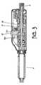
- FIG. 3shows a first embodiment of an injection device according to the invention with a released threaded rod and a pushed unlocking slide, the control button not being pushed;
- FIG. 4shows a cross sectional view along line A—A of FIG. 1;
- FIG. 5shows a perspective view of a spreader bushing surrounding a threaded flange according to the invention
- FIG. 6shows a second embodiment of an injection device according to the invention with the container not being inserted
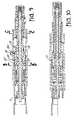
- FIG. 7shows the injection device of FIG. 6 with the inserted container
- FIG. 8shows the injection device of FIG. 7 with the control button being pushed
- FIG. 9shows the injection device of FIG. 7 with the threaded rod being released
- FIG. 10shows the injection device of FIG. 7 in a cross-sectional view perpendicular to the view of FIG. 7;
- FIG. 11shows a cross sectional view along line B—B of FIG. 9;
- FIG. 12shows a cross sectional view along line A—A of FIG. 8;
- FIG. 13shows a cross sectional view along line C—C of FIG. 9;
- FIG. 14shows an injection device of the prior art with a retained threaded rod
- FIG. 16shows an injection device of the prior art in which the actuating device has been removed
- FIG. 17shows a cross section along line A—A of FIG. 14;
- FIG. 18shows a cross section along line B—B of FIG. 15.
- FIG. 19shows a cross section along line C—C of FIG. 15 .
- FIGS. 14 to 19Reference is made to the above description of FIGS. 14 to 19 for the general function of the inventive injection device, except the function of the unlocking slide 32 , spreader bushing 37 and flanges 27 and 27 ′.
- the actuating device 7comprises a control button 8 , a threaded rod 9 with a flange 19 , a guide member 24 and a driving member 11 .
- the tubular driving member 11is rigidly connected to the control button 8 .
- the control button 8When the control button 8 is actuated, for example rotated or pushed, the corresponding movement is transferred to the driving member 11 , the spreader bushing 37 and the threaded flanges 27 , 27 ′.
- the threaded flanges 27 , 27 ′engage with the threaded rod 9 during normal operation.
- the spreader bushing 37surrounds both the driving member 11 and the threaded flanges 27 , 27 ′ and moves with them during normal operation.
- the driving member 11When turning the control button 8 to adjust an injection dose, the driving member 11 is also turned. This rotating movement can, however, not directly be transferred to the threaded rod 9 as the rod 9 is rigidly seated in the guide member 24 .
- projections of the driving member 11 (not shown) or of any other suitable element to transfer a movement of the driving memberengage with recesses 37 a , 37 b of the spreader bushing 37 to rotate the spreader bushing 37 when the driving member 11 is turned.
- Projections 37 c , 37 d of the spreader bushing 37engage with projections 27 a or 27 b of a first flange 27 shown in FIG.
- the spreader bushing 37is also moved in the proximal direction when pressing control button 8 to remain basically in the same relative position to the flanges 27 , 27 ′.
- the axial movementis effected against the bias of a spring 16 , returning the actuating device 7 to its home position after injection, as shown in FIG. 1 .
- the threaded rod 9When the fluid container 4 is empty and the threaded rod 9 is therefore in an extreme proximal position, the threaded rod must be returned to an extreme distal position.
- the injection device according to the inventionallows the threaded rod 9 to be returned only by activation of the unlocking slide 32 , as shown in FIG. 3 .
- the blocking element 36 ais moved to a proximal position, thereby allowing the unlocking slide 32 to be moved in a direction to engage with a recess 37 e of the spreader bushing 37 , which either directly causes a movement of the spreader bushing in the distal direction, relative to the flanges 27 , 27 ′, thus spreading flanges 27 , 27 ′ open.
- This movementcan be effected by the provision of tilted surfaces effecting an axial movement of spreader bushing 37 when moving unlocking slide 32 in radial direction. It is also possible to effect this movement by simply engaging unlocking slide 32 with spreader bushing 37 and subsequent axial movement of slide 32 .
- spreader bushing 37Since the spreader bushing 37 is moved together with the flanges 27 , 27 ′ during normal operation, spreader bushing 37 can always be in a position close to the flanges 27 , 27 ′ so that only a short relative movement of the spreader bushing 37 is required to spread flanges 27 , 27 ′ open. Thus, control button 8 does not have to be pressed to unlock rod 9 .
- FIGS. 4 and 5show that both threaded flanges 27 , 27 ′ are designed as two half-shelf threaded nut sections which surround the rod 9 having circular surfaces 13 , 13 ′ being threaded which engage with the threaded surface 27 c on the inner side of flanges 27 , 27 ′.
- the outer diameter of the threaded flanges 27 , 27 ′becomes smaller in distal direction.
- Projections 27 a , 27 b , 27 ′ a , 27 ′ b of the flanges 27 , 27 ′are positioned to form grooves G between the respective projections 27 a and 27 ′ a or 27 b and 27 ′ b which become smaller in the distal direction.
- Projections 37 c , 37 d of the spreader bushing 37form a wedge-shaped part 37 g having a width gradually decreasing in the distal direction, so that if the spreader bushing 37 is moved relative to the flanges 27 , 27 ′, the flanges 27 , 27 ′ are guided by grooves 37 h , 37 i adjacent the wedge-shaped part 37 g to thereby open or close the flanges 27 , 27 ′.
- Recessescan be provided at a variety of positions along bushing 37 , so that more than the shown recesses 37 e and 37 f can be provided.
- the recessescan either be formed around bushing 37 or only at district portions, as shown in FIG. 5 .
- Notchescan be provided to allow rotations of bushing 37 only with a predefined angle in the end position.
- FIGS. 6 to 13A second embodiment of the invention is described with reference to FIGS. 6 to 13 .
- FIG. 6shows an injection device according to a second embodiment of the invention.
- the container 4is not inserted.
- spreader bushing 37has two recesses 37 e , 37 f surrounding the spreader bushing 37 .
- Unlocking slide 32can engage with spreader bushing 37 using either of the recesses 37 e , 37 f so that spreader bushing 37 can be moved relative to the flanges 27 , 27 ′ in two positions of the injection device, namely with control button 8 being in the normal position, as shown in FIG.
- the flanges 27 , 27 ′can be spread open starting from two positions of the injection device, namely with control button 8 being in the normal position, or control button 8 being pressed.
- only one element, namely unlocking slide 32has to be actuated by the user to unlock rod 9 to allow it to be moved to the distal position, when the injection device is held with the distal end facing downwards.
- the engaging portion of unlocking slide 32can be tilted with respect to the axial direction of the injection device to cause an immediate movement of spreader bushing 37 , when unlocking slide 32 is pressed down, as shown schematically in FIG. 3 of the first embodiment.
- it is also possible to provide the possibility for engagement of unlocking slide 32 with spreader bushing 37so that the user first has to perform an engaging operation, for example by pressing down unlocking slide 32 of FIG. 6, and then has to perform a shifting operation by moving unlocking slide 32 coupled with spreader bushing 37 in the distal direction, thus effecting a movement of spreader bushing 37 in the distal direction relative to flanges 27 , 27 ′, thus spreading flanges 27 , 27 ′ open.
- it is also possible to provide a mechanism which will open the flanges 27 , 27 ′ by any other movement of unlocking slide 32e.g. in the proximal direction.
- control button 8is turned to adjust a dose to be injected, as described above, and is then pressed to move rod 9 in a proximal direction, thereby injecting the preset dose.
- Spreader bushing 37is moved together with driving member 11 during normal operation and remains thus in a basical fixed relative relationship.
- unlocking slide 32can be released, thus effecting that spring 38 pushes spreader bushing 37 back to its normal position, thereby again engaging the threaded flanges 27 , 27 ′ with the threaded surfaces 13 , 13 ′ of rod 9 .
- FIG. 10again shows the basic concept of the inventive injection device with a cross-sectional view in a plane turned by 90° with respect to the cross-sectional views described above.
- FIG. 11shows a cross-sectional view along line B—B of FIG. 9 .
- Flanges 27 , 27 ′are spread open by the wedge-shaped elements 37 g of spreader bushing 37 , which engage with the projection 27 a , 27 b of flange 27 which are shown and described with reference to FIG. 5, and the corresponding projections of flange 27 ′.
- FIG. 12shows the flanges 27 , 27 ′ in a closed condition being engaged with rod 9 , seen in the cross-sectional view along line A—A in FIG. 8 .
- spreader bushing 37is in a more proximal position relative to the flanges 27 , 27 ′, as compared to the state shown in FIG. 11 .
- FIG. 13is a cross-sectional view along line C—C in FIG. 9 and shows the coaxial arrangement of the inventive injection device.
Landscapes
- Health & Medical Sciences (AREA)
- Vascular Medicine (AREA)
- Engineering & Computer Science (AREA)
- Anesthesiology (AREA)
- Biomedical Technology (AREA)
- Heart & Thoracic Surgery (AREA)
- Hematology (AREA)
- Life Sciences & Earth Sciences (AREA)
- Animal Behavior & Ethology (AREA)
- General Health & Medical Sciences (AREA)
- Public Health (AREA)
- Veterinary Medicine (AREA)
- Infusion, Injection, And Reservoir Apparatuses (AREA)
Abstract
Description
Claims (19)
Priority Applications (1)
| Application Number | Priority Date | Filing Date | Title |
|---|---|---|---|
| US09/784,661US6673049B2 (en) | 2001-02-15 | 2001-02-15 | Injection device for injecting fluid |
Applications Claiming Priority (1)
| Application Number | Priority Date | Filing Date | Title |
|---|---|---|---|
| US09/784,661US6673049B2 (en) | 2001-02-15 | 2001-02-15 | Injection device for injecting fluid |
Publications (2)
| Publication Number | Publication Date |
|---|---|
| US20020111587A1 US20020111587A1 (en) | 2002-08-15 |
| US6673049B2true US6673049B2 (en) | 2004-01-06 |
Family
ID=25133136
Family Applications (1)
| Application Number | Title | Priority Date | Filing Date |
|---|---|---|---|
| US09/784,661Expired - Fee RelatedUS6673049B2 (en) | 2001-02-15 | 2001-02-15 | Injection device for injecting fluid |
Country Status (1)
| Country | Link |
|---|---|
| US (1) | US6673049B2 (en) |
Cited By (46)
| Publication number | Priority date | Publication date | Assignee | Title |
|---|---|---|---|---|
| US20040236340A1 (en)* | 2001-09-19 | 2004-11-25 | Yves Cirotteau | Device for delivering a biomaterial |
| WO2005025637A2 (en) | 2003-09-17 | 2005-03-24 | Dali Medical Devices Ltd. | Automatic needle device |
| US20070129686A1 (en)* | 2003-09-17 | 2007-06-07 | Dali Medical Devices Ltd. | Automatic injection device |
| US20080051712A1 (en)* | 2004-12-31 | 2008-02-28 | Patrick Fiechter | Device for the dosed administration of a fluid product, provided with a coupling |
| US20080306446A1 (en)* | 2005-01-21 | 2008-12-11 | Novo Nordisk A/S | Automatic Injection Device with a Top Release Mechanism |
| US20080312591A1 (en)* | 2004-05-28 | 2008-12-18 | Nigel Harrison | Injection Device |
| US20080312590A1 (en)* | 2004-05-28 | 2008-12-18 | Tim Barrow-Williams | Injection Device |
| US20080312602A1 (en)* | 2005-04-06 | 2008-12-18 | Timothy Donald Barrow-Williams | Injection Device (Bayonet Cap Removal) |
| US20080312593A1 (en)* | 2005-04-06 | 2008-12-18 | Rosemary Louise Habeshaw | Injection Device |
| US20080312592A1 (en)* | 2004-05-28 | 2008-12-18 | Tim Barrow-Williams | Injection Device |
| US20080312606A1 (en)* | 2004-05-28 | 2008-12-18 | Nigel Harrison | Injection Device |
| US20090054849A1 (en)* | 2004-05-28 | 2009-02-26 | Cilag Ag International | Injection device |
| US20090054838A1 (en)* | 2004-05-28 | 2009-02-26 | Cilag Ag International | Injection device |
| US20090088688A1 (en)* | 2005-04-06 | 2009-04-02 | Barrow-Williams Timothy Donald | Injection device |
| US20090171296A1 (en)* | 2005-08-30 | 2009-07-02 | Arthur Fabian | Needle assembly for a prefilled syringe system |
| US20090234297A1 (en)* | 2005-04-06 | 2009-09-17 | Douglas Ivan Jennings | Injection device |
| US20090234298A1 (en)* | 2005-04-06 | 2009-09-17 | Rosemary Louise Habeshaw | Injection device |
| US20100016794A1 (en)* | 2006-06-01 | 2010-01-21 | Joseph Peter Corrigan | Injection Device |
| US20100036318A1 (en)* | 2006-10-19 | 2010-02-11 | Elcam Medical Agricultural Cooperative Association | Automatic injection device |
| US7901377B1 (en) | 2004-05-28 | 2011-03-08 | Cilag Gmbh International | Injection device |
| US20110092954A1 (en)* | 2008-06-19 | 2011-04-21 | Douglas Ivan Jennings | Reusable Auto-Injector |
| US20110098670A1 (en)* | 2008-06-19 | 2011-04-28 | Rosemary Louise Burnell | Fluid Transfer Assembly |
| US20110098657A1 (en)* | 2008-06-16 | 2011-04-28 | Douglas Ivan Jennings | Reusable Auto-Injector |
| US20110098647A1 (en)* | 2008-06-19 | 2011-04-28 | Douglas Ivan Jennings | Auto-Injector with Filling Means |
| US20110098656A1 (en)* | 2005-09-27 | 2011-04-28 | Burnell Rosie L | Auto-injection device with needle protecting cap having outer and inner sleeves |
| US20110098655A1 (en)* | 2008-06-19 | 2011-04-28 | Douglas Ivan Jennings | Automatic Injection Device with Trigger Lock |
| US20110178469A1 (en)* | 2004-05-28 | 2011-07-21 | Cilag Ag International | Injection device |
| US7985216B2 (en) | 2004-03-16 | 2011-07-26 | Dali Medical Devices Ltd. | Medicinal container engagement and automatic needle device |
| US8177772B2 (en) | 2005-09-26 | 2012-05-15 | C. R. Bard, Inc. | Catheter connection systems |
| US8313465B2 (en) | 2004-05-28 | 2012-11-20 | Cilag Gmbh International | Injection device |
| US8313464B2 (en) | 2004-05-28 | 2012-11-20 | Cilag Gmbh International | Injection device |
| US8337475B2 (en) | 2004-10-12 | 2012-12-25 | C. R. Bard, Inc. | Corporeal drainage system |
| US8535268B2 (en) | 2010-12-22 | 2013-09-17 | Alcon Research, Ltd. | Device for at least one of injection or aspiration |
| US8636721B2 (en) | 2003-11-20 | 2014-01-28 | Henry M. Jackson Foundation For The Advancement Of Military Medicine, Inc. | Portable hand pump for evacuation of fluids |
| US8968236B2 (en) | 2005-04-06 | 2015-03-03 | Cilag Gmbh International | Injection device |
| US8992477B2 (en) | 2011-01-24 | 2015-03-31 | Elcam Agricultural Cooperative Association Ltd. | Injector |
| US9028451B2 (en) | 2006-06-01 | 2015-05-12 | Cilag Gmbh International | Injection device |
| US9072833B2 (en) | 2006-06-01 | 2015-07-07 | Cilag Gmbh International | Injection device |
| US9682194B2 (en) | 2008-06-19 | 2017-06-20 | Cilag Gmbh International | Re-useable auto-injector with filling means |
| JP2017536155A (en)* | 2014-10-29 | 2017-12-07 | ウォックハート リミテッドWockhardt Limited | Drug delivery device for delivering two or more independently selectable multiple doses of drugs with user-operable variable dose locking mechanism |
| US10709849B2 (en) | 2013-06-11 | 2020-07-14 | Cilag Gmbh International | Guide for an injection device |
| US10799646B2 (en) | 2013-06-11 | 2020-10-13 | Cilag Gmbh International | Injection device |
| US11123492B2 (en) | 2013-06-11 | 2021-09-21 | Cilag Gmbh International | Injection device |
| US11173255B2 (en) | 2013-06-11 | 2021-11-16 | Cilag Gmbh International | Injection device |
| US11344318B2 (en) | 2016-07-18 | 2022-05-31 | Merit Medical Systems, Inc. | Inflatable radial artery compression device |
| US12426864B2 (en) | 2021-06-18 | 2025-09-30 | Merit Medical Systems, Inc. | Hemostasis devices and methods of use |
Families Citing this family (14)
| Publication number | Priority date | Publication date | Assignee | Title |
|---|---|---|---|---|
| DE10343548B4 (en)* | 2003-09-19 | 2008-03-27 | Tecpharma Licensing Ag | Device for metered delivery of an injectable product |
| GB0414054D0 (en) | 2004-06-23 | 2004-07-28 | Owen Mumford Ltd | Improvements relating to automatic injection devices |
| DE102004042886A1 (en)* | 2004-09-04 | 2006-03-30 | Roche Diagnostics Gmbh | Lancet device for creating a puncture wound |
| DE102004059126B4 (en)* | 2004-12-08 | 2014-01-16 | Roche Diagnostics Gmbh | Adapter for injection device |
| KR101396797B1 (en) | 2006-06-30 | 2014-05-26 | 애브비 바이오테크놀로지 리미티드 | Automatic injection device |
| WO2010127146A1 (en) | 2009-04-29 | 2010-11-04 | Abbott Biotechnology Ltd | Automatic injection device |
| CA2777118A1 (en)* | 2009-10-16 | 2011-04-21 | Sanofi-Aventis Deutschland Gmbh | Drug delivery device |
| EP2512558A4 (en) | 2009-12-15 | 2014-08-13 | Abbvie Biotechnology Ltd | IMPROVED TRIP PUSHER FOR AUTOMATIC INJECTION DEVICE |
| NZ702172A (en) | 2010-04-21 | 2016-03-31 | Abbvie Biotechnology Ltd | Wearable automatic injection device for controlled delivery of therapeutic agents |
| JP2013528086A (en)* | 2010-06-11 | 2013-07-08 | サノフィ−アベンティス・ドイチュラント・ゲゼルシャフト・ミット・ベシュレンクテル・ハフツング | Assembly for drug delivery device and drug delivery device |
| US9498576B2 (en)* | 2010-06-11 | 2016-11-22 | Sanofi-Aventis Deutschland Gmbh | Drive mechanism for a drug delivery device |
| WO2012062718A1 (en)* | 2010-11-08 | 2012-05-18 | Sanofi-Aventis Deutschland Gmbh | Dose setting mechanism for a drug delivery device, drug delivery system and drug delivery device |
| KR101989342B1 (en) | 2011-01-24 | 2019-06-14 | 애브비 바이오테크놀로지 리미티드 | Removal of needle shields from syringes and automatic injection devices |
| BR112013018905B1 (en) | 2011-01-24 | 2021-07-13 | Abbvie Biotechnology Ltd | AUTOMATIC INJECTION DEVICES THAT HAVE OVERMOLDED HANDLE SURFACES. |
Citations (45)
| Publication number | Priority date | Publication date | Assignee | Title |
|---|---|---|---|---|
| US2531267A (en) | 1947-10-16 | 1950-11-21 | Harnisch Fritz | Hypodermic syringe operating device |
| US3605744A (en) | 1969-04-22 | 1971-09-20 | Edward M Dwyer | Injection apparatus and method of injecting |
| EP0037696A1 (en) | 1980-04-08 | 1981-10-14 | Greater Glasgow Health Board | Dispensing device |
| EP0143895A1 (en) | 1983-09-07 | 1985-06-12 | Disetronic Ag | Portable infusion apparatus |
| WO1985005275A1 (en) | 1984-05-12 | 1985-12-05 | Dieter Lucas | Injection syringe |
| US4592745A (en) | 1984-02-29 | 1986-06-03 | Novo Industri A/S | Dispenser |
| WO1987002895A1 (en) | 1985-11-08 | 1987-05-21 | Disetronic Ag | Injection instrument |
| EP0268191A2 (en) | 1986-11-14 | 1988-05-25 | WILHELM HASELMEIER GMBH & CO. | Injection device |
| WO1988008725A1 (en) | 1987-05-08 | 1988-11-17 | Wilhelm Haselmeier Gmbh + Co. | Injection device with a loading element and a second setting element |
| DE3900926A1 (en) | 1988-02-08 | 1989-08-17 | Disetronic Ag | Injection device |
| EP0338806A2 (en) | 1988-04-18 | 1989-10-25 | Turner, Robert Charles | Syringes |
| EP0373321A1 (en) | 1988-10-19 | 1990-06-20 | Byk Gulden Lomberg Chemische Fabrik GmbH | Reusable injection device for the delivery of a preselected dose |
| WO1991010460A1 (en) | 1990-01-22 | 1991-07-25 | Novo Nordisk A/S | A process and apparatus for mixing and injecting a medicine |
| DE4013769A1 (en) | 1990-04-28 | 1991-10-31 | Adamaszek Franz Heinz | Automatic insulin injection device - includes rotating knob to allow vol. of insulin to be accurately chosen |
| WO1992018179A1 (en) | 1991-04-15 | 1992-10-29 | Medico Development Investment Company | Injection device |
| EP0518416A1 (en) | 1991-06-13 | 1992-12-16 | Duphar International Research B.V | Injection device |
| DE4223958A1 (en) | 1991-07-24 | 1993-01-28 | Medico Dev Investment Co | INJECTOR |
| WO1993016740A2 (en) | 1992-02-21 | 1993-09-02 | Medimpex Ets. | Injection device |
| US5244465A (en) | 1988-10-19 | 1993-09-14 | Byk Gulden Lomberg Chemische Fabrik Gmbh | Reusable injection device for distributing a preselected dose |
| US5295976A (en) | 1990-04-04 | 1994-03-22 | Eli Lilly And Company | Dose indicating injection pen |
| FR2701211A1 (en) | 1993-02-08 | 1994-08-12 | Aguettant Lab | Metering instrument, in particular for injection. |
| US5338311A (en) | 1993-08-23 | 1994-08-16 | Mahurkar Sakharam D | Hypodermic needle assembly |
| EP0627229A1 (en) | 1993-06-04 | 1994-12-07 | Medimpex Ets. | Dosing means for a syringe |
| WO1995001812A1 (en) | 1993-07-09 | 1995-01-19 | Disetronic Ag | Needle system fastening mechanism |
| US5435076A (en) | 1992-04-21 | 1995-07-25 | Pharmacia Aktiebolag | Injection device |
| DE19519147A1 (en) | 1994-05-30 | 1995-12-07 | Medico Dev Investment Co | Unit for injecting fluid into patient |
| WO1996007443A1 (en) | 1994-09-08 | 1996-03-14 | Owen Mumford Limited | Improvements relating to injection devices |
| US5514097A (en) | 1994-02-14 | 1996-05-07 | Genentech, Inc. | Self administered injection pen apparatus and method |
| US5540664A (en) | 1993-05-27 | 1996-07-30 | Washington Biotech Corporation | Reloadable automatic or manual emergency injection system |
| EP0730876A2 (en) | 1995-03-07 | 1996-09-11 | Eli Lilly And Company | Recyclable medication dispensing device |
| US5584815A (en) | 1993-04-02 | 1996-12-17 | Eli Lilly And Company | Multi-cartridge medication injection device |
| WO1997017096A1 (en) | 1995-11-09 | 1997-05-15 | Disetronic Licensing Ag | Injection device |
| US5643214A (en)* | 1993-05-18 | 1997-07-01 | Owen Mumford Limited | Injection devices |
| US5658259A (en)* | 1995-10-19 | 1997-08-19 | Meridian Medical Technologies, Inc. | Dental cartridge assembly auto-injector with protective needle cover |
| EP0554995B1 (en) | 1992-02-04 | 1997-12-17 | Becton, Dickinson and Company | Reusable medication delivery pen |
| WO1998001172A1 (en)* | 1996-07-05 | 1998-01-15 | Disetronic Licensing Ag | Injection device for injection of liquid |
| US5728075A (en) | 1993-10-29 | 1998-03-17 | Pharmacia & Upjohn Aktiebolag | Injection devices |
| US5779677A (en) | 1994-01-17 | 1998-07-14 | Laboratoire Aguettant | Automatic drug injector |
| US5851197A (en) | 1997-02-05 | 1998-12-22 | Minimed Inc. | Injector for a subcutaneous infusion set |
| DE19822031A1 (en) | 1998-05-15 | 1999-11-18 | Disetronic Licensing Ag | Auto injection device |
| US6042571A (en) | 1996-07-01 | 2000-03-28 | Pharmacia & Upjohn Aktiebolag | Injection device |
| US6059755A (en) | 1995-11-09 | 2000-05-09 | Disetronic Licensing Ag | Injection device for a liquid medicament |
| US6086567A (en) | 1996-04-02 | 2000-07-11 | Disetronic Licensing Ag | Injection device |
| US6093172A (en) | 1997-02-05 | 2000-07-25 | Minimed Inc. | Injector for a subcutaneous insertion set |
| US6096010A (en) | 1998-02-20 | 2000-08-01 | Becton, Dickinson And Company | Repeat-dose medication delivery pen |
- 2001
- 2001-02-15USUS09/784,661patent/US6673049B2/ennot_activeExpired - Fee Related
Patent Citations (57)
| Publication number | Priority date | Publication date | Assignee | Title |
|---|---|---|---|---|
| US2531267A (en) | 1947-10-16 | 1950-11-21 | Harnisch Fritz | Hypodermic syringe operating device |
| US3605744A (en) | 1969-04-22 | 1971-09-20 | Edward M Dwyer | Injection apparatus and method of injecting |
| EP0037696A1 (en) | 1980-04-08 | 1981-10-14 | Greater Glasgow Health Board | Dispensing device |
| EP0143895A1 (en) | 1983-09-07 | 1985-06-12 | Disetronic Ag | Portable infusion apparatus |
| US4592745A (en) | 1984-02-29 | 1986-06-03 | Novo Industri A/S | Dispenser |
| WO1985005275A1 (en) | 1984-05-12 | 1985-12-05 | Dieter Lucas | Injection syringe |
| US4883472A (en) | 1985-11-08 | 1989-11-28 | Disetronic Ag. | Injection device |
| WO1987002895A1 (en) | 1985-11-08 | 1987-05-21 | Disetronic Ag | Injection instrument |
| EP0245312A1 (en) | 1985-11-08 | 1987-11-19 | Disetronic Ag | Injection instrument. |
| EP0268191A2 (en) | 1986-11-14 | 1988-05-25 | WILHELM HASELMEIER GMBH & CO. | Injection device |
| DE3638984A1 (en) | 1986-11-14 | 1988-05-26 | Haselmeier Wilhelm Fa | Injection appliance |
| US5114406A (en) | 1986-11-14 | 1992-05-19 | Wilhelm Haselmeier Gmbh & Co. | Injection device for injection, especially self-administered injection, of medicament, including mechanisms for nulling and for selecting dosage, especially for use with multi-dose ampules |
| WO1988008725A1 (en) | 1987-05-08 | 1988-11-17 | Wilhelm Haselmeier Gmbh + Co. | Injection device with a loading element and a second setting element |
| US5092842A (en) | 1987-05-08 | 1992-03-03 | Wilhelm Haselmeier Gmbh & Co. | Injection device with a cocking element and a second setting element |
| DE3900926A1 (en) | 1988-02-08 | 1989-08-17 | Disetronic Ag | Injection device |
| EP0338806A2 (en) | 1988-04-18 | 1989-10-25 | Turner, Robert Charles | Syringes |
| EP0373321A1 (en) | 1988-10-19 | 1990-06-20 | Byk Gulden Lomberg Chemische Fabrik GmbH | Reusable injection device for the delivery of a preselected dose |
| US5244465A (en) | 1988-10-19 | 1993-09-14 | Byk Gulden Lomberg Chemische Fabrik Gmbh | Reusable injection device for distributing a preselected dose |
| WO1991010460A1 (en) | 1990-01-22 | 1991-07-25 | Novo Nordisk A/S | A process and apparatus for mixing and injecting a medicine |
| US5295976A (en) | 1990-04-04 | 1994-03-22 | Eli Lilly And Company | Dose indicating injection pen |
| DE4013769A1 (en) | 1990-04-28 | 1991-10-31 | Adamaszek Franz Heinz | Automatic insulin injection device - includes rotating knob to allow vol. of insulin to be accurately chosen |
| WO1992018179A1 (en) | 1991-04-15 | 1992-10-29 | Medico Development Investment Company | Injection device |
| US5591136A (en) | 1991-04-15 | 1997-01-07 | Medico Development Investment Company | Injection device |
| EP0518416A1 (en) | 1991-06-13 | 1992-12-16 | Duphar International Research B.V | Injection device |
| US5273544A (en) | 1991-06-13 | 1993-12-28 | Duphar International Research B.V. | Injection device |
| DE4223958A1 (en) | 1991-07-24 | 1993-01-28 | Medico Dev Investment Co | INJECTOR |
| EP0554995B1 (en) | 1992-02-04 | 1997-12-17 | Becton, Dickinson and Company | Reusable medication delivery pen |
| WO1993016740A2 (en) | 1992-02-21 | 1993-09-02 | Medimpex Ets. | Injection device |
| US5370629A (en) | 1992-02-21 | 1994-12-06 | Medimpex Ets. | Injection device |
| US5435076A (en) | 1992-04-21 | 1995-07-25 | Pharmacia Aktiebolag | Injection device |
| US5807346A (en) | 1993-02-08 | 1998-09-15 | Laboratoire Aguettant | Metering instrument, particularly for injecting medicinal liquid |
| FR2701211A1 (en) | 1993-02-08 | 1994-08-12 | Aguettant Lab | Metering instrument, in particular for injection. |
| US5584815A (en) | 1993-04-02 | 1996-12-17 | Eli Lilly And Company | Multi-cartridge medication injection device |
| US5496293A (en) | 1993-04-06 | 1996-03-05 | Medimpex Ets. | Advancing mechanism for an injection device |
| US5643214A (en)* | 1993-05-18 | 1997-07-01 | Owen Mumford Limited | Injection devices |
| US5540664A (en) | 1993-05-27 | 1996-07-30 | Washington Biotech Corporation | Reloadable automatic or manual emergency injection system |
| EP0627229A1 (en) | 1993-06-04 | 1994-12-07 | Medimpex Ets. | Dosing means for a syringe |
| WO1995001812A1 (en) | 1993-07-09 | 1995-01-19 | Disetronic Ag | Needle system fastening mechanism |
| US5338311A (en) | 1993-08-23 | 1994-08-16 | Mahurkar Sakharam D | Hypodermic needle assembly |
| US6004298A (en) | 1993-10-29 | 1999-12-21 | Pharmacia & Upjohn Aktiebolag | Injection devices |
| US5728075A (en) | 1993-10-29 | 1998-03-17 | Pharmacia & Upjohn Aktiebolag | Injection devices |
| US5779677A (en) | 1994-01-17 | 1998-07-14 | Laboratoire Aguettant | Automatic drug injector |
| US5514097A (en) | 1994-02-14 | 1996-05-07 | Genentech, Inc. | Self administered injection pen apparatus and method |
| DE19519147A1 (en) | 1994-05-30 | 1995-12-07 | Medico Dev Investment Co | Unit for injecting fluid into patient |
| WO1996007443A1 (en) | 1994-09-08 | 1996-03-14 | Owen Mumford Limited | Improvements relating to injection devices |
| EP0730876A2 (en) | 1995-03-07 | 1996-09-11 | Eli Lilly And Company | Recyclable medication dispensing device |
| US5658259A (en)* | 1995-10-19 | 1997-08-19 | Meridian Medical Technologies, Inc. | Dental cartridge assembly auto-injector with protective needle cover |
| WO1997017096A1 (en) | 1995-11-09 | 1997-05-15 | Disetronic Licensing Ag | Injection device |
| US6059755A (en) | 1995-11-09 | 2000-05-09 | Disetronic Licensing Ag | Injection device for a liquid medicament |
| US6086567A (en) | 1996-04-02 | 2000-07-11 | Disetronic Licensing Ag | Injection device |
| US6042571A (en) | 1996-07-01 | 2000-03-28 | Pharmacia & Upjohn Aktiebolag | Injection device |
| WO1998001172A1 (en)* | 1996-07-05 | 1998-01-15 | Disetronic Licensing Ag | Injection device for injection of liquid |
| US6090080A (en)* | 1996-07-05 | 2000-07-18 | Disetronic Licensing Ag | Injection device for injection of liquid |
| US5851197A (en) | 1997-02-05 | 1998-12-22 | Minimed Inc. | Injector for a subcutaneous infusion set |
| US6093172A (en) | 1997-02-05 | 2000-07-25 | Minimed Inc. | Injector for a subcutaneous insertion set |
| US6096010A (en) | 1998-02-20 | 2000-08-01 | Becton, Dickinson And Company | Repeat-dose medication delivery pen |
| DE19822031A1 (en) | 1998-05-15 | 1999-11-18 | Disetronic Licensing Ag | Auto injection device |
Non-Patent Citations (2)
| Title |
|---|
| Jost et al., Injection Device for Injection of Liquid, Sep. 21, 1998, USPTO.* |
| US 5,954,699, 9/1999, Jost et al. (withdrawn) |
Cited By (95)
| Publication number | Priority date | Publication date | Assignee | Title |
|---|---|---|---|---|
| US7306611B2 (en)* | 2001-09-19 | 2007-12-11 | Bio Holdings International Limited | Device for delivering a biomaterial |
| US20040236340A1 (en)* | 2001-09-19 | 2004-11-25 | Yves Cirotteau | Device for delivering a biomaterial |
| US20110152783A1 (en)* | 2003-09-17 | 2011-06-23 | Dali Medical Devices Ltd. | Automatic needle device |
| WO2005025637A2 (en) | 2003-09-17 | 2005-03-24 | Dali Medical Devices Ltd. | Automatic needle device |
| US20070118081A1 (en)* | 2003-09-17 | 2007-05-24 | Dali Medical Devices Ltd. | Automatic needle device |
| US11623051B2 (en) | 2003-09-17 | 2023-04-11 | E3D Agricultural Cooperative Association Ltd. | Automatic injection device |
| US20070129686A1 (en)* | 2003-09-17 | 2007-06-07 | Dali Medical Devices Ltd. | Automatic injection device |
| EP2650033A2 (en) | 2003-09-17 | 2013-10-16 | Elcam Medical Agricultural Cooperative Association Ltd. | Automatic injection device |
| US8376998B2 (en) | 2003-09-17 | 2013-02-19 | Elcam Medical Agricultural Cooperative Association Ltd. | Automatic injection device |
| US7901382B2 (en) | 2003-09-17 | 2011-03-08 | Dali Medical Devices, Ltd. | Automatic needle device |
| US8328765B2 (en) | 2003-09-17 | 2012-12-11 | Dali Medical Devices Ltd. | Automatic needle device |
| US10213532B2 (en) | 2003-11-20 | 2019-02-26 | The Henry M. Jackson Foundation For The Advancement Of Military Medicine, Inc. | Portable hand pump for evacuation of fluids |
| US9393353B2 (en) | 2003-11-20 | 2016-07-19 | The Henry M. Jackson Foundation For The Advancement Of Military Medicine, Inc. | Portable hand pump for evacuation of fluids |
| US9907887B2 (en) | 2003-11-20 | 2018-03-06 | The Henry M. Jackson Foundation For The Advancement Of Military Medicine, Inc. | Portable hand pump for evacuation of fluids |
| US8636721B2 (en) | 2003-11-20 | 2014-01-28 | Henry M. Jackson Foundation For The Advancement Of Military Medicine, Inc. | Portable hand pump for evacuation of fluids |
| US7985216B2 (en) | 2004-03-16 | 2011-07-26 | Dali Medical Devices Ltd. | Medicinal container engagement and automatic needle device |
| US20080312591A1 (en)* | 2004-05-28 | 2008-12-18 | Nigel Harrison | Injection Device |
| US9675758B2 (en) | 2004-05-28 | 2017-06-13 | Cilag Gmbh International | Injection device |
| US20090054838A1 (en)* | 2004-05-28 | 2009-02-26 | Cilag Ag International | Injection device |
| US20090054849A1 (en)* | 2004-05-28 | 2009-02-26 | Cilag Ag International | Injection device |
| US20080312606A1 (en)* | 2004-05-28 | 2008-12-18 | Nigel Harrison | Injection Device |
| US8343110B2 (en) | 2004-05-28 | 2013-01-01 | Cilag Gmbh International | Injection device |
| US7785292B2 (en) | 2004-05-28 | 2010-08-31 | Ethicon Endo-Surgery, Inc. | Injection device |
| US7901377B1 (en) | 2004-05-28 | 2011-03-08 | Cilag Gmbh International | Injection device |
| US20080312592A1 (en)* | 2004-05-28 | 2008-12-18 | Tim Barrow-Williams | Injection Device |
| US9675757B2 (en) | 2004-05-28 | 2017-06-13 | Cilag Gmbh International | Injection device |
| US9895493B2 (en) | 2004-05-28 | 2018-02-20 | Cilag Gmbh International | Injection device |
| US8313464B2 (en) | 2004-05-28 | 2012-11-20 | Cilag Gmbh International | Injection device |
| US8313463B2 (en) | 2004-05-28 | 2012-11-20 | Cilag Gmbh International | Injection device |
| US8313465B2 (en) | 2004-05-28 | 2012-11-20 | Cilag Gmbh International | Injection device |
| US8277414B2 (en) | 2004-05-28 | 2012-10-02 | Cilag Gmbh International | Injection device |
| US20080312590A1 (en)* | 2004-05-28 | 2008-12-18 | Tim Barrow-Williams | Injection Device |
| US20110178469A1 (en)* | 2004-05-28 | 2011-07-21 | Cilag Ag International | Injection device |
| US8337475B2 (en) | 2004-10-12 | 2012-12-25 | C. R. Bard, Inc. | Corporeal drainage system |
| US10946123B2 (en) | 2004-10-12 | 2021-03-16 | Merit Medical Systems, Inc. | Corporeal drainage system |
| US9913935B2 (en) | 2004-10-12 | 2018-03-13 | C. R. Bard, Inc. | Corporeal drainage system |
| US9295764B2 (en) | 2004-10-12 | 2016-03-29 | C. R. Bard, Inc. | Corporeal drainage system |
| US8814839B2 (en) | 2004-10-12 | 2014-08-26 | C. R. Bard, Inc. | Corporeal drainage system |
| US20080051713A1 (en)* | 2004-12-31 | 2008-02-28 | Philippe Kohlbrenner | Device for the dosed administration of a fluid product comprising a torsion spring drive |
| US20080051712A1 (en)* | 2004-12-31 | 2008-02-28 | Patrick Fiechter | Device for the dosed administration of a fluid product, provided with a coupling |
| US7951113B2 (en)* | 2004-12-31 | 2011-05-31 | Tecpharma Licensing Ag | Device for the dosed administration of a fluid product comprising a torsion spring drive |
| US8409148B2 (en)* | 2004-12-31 | 2013-04-02 | Tecpharma Licensing Ag | Device for the dosed administration of a fluid product, provided with a coupling |
| US11311679B2 (en) | 2005-01-21 | 2022-04-26 | Novo Nordisk A/S | Automatic injection device with a top release mechanism |
| US10376652B2 (en) | 2005-01-21 | 2019-08-13 | Novo Nordisk A/S | Automatic injection device with a top release mechanism |
| US12070586B2 (en) | 2005-01-21 | 2024-08-27 | Novo Nordisk A/S | Automatic injection device with a top release mechanism |
| US8096978B2 (en)* | 2005-01-21 | 2012-01-17 | Novo Nordisk A/S | Automatic injection device with a top release mechanism |
| AU2006207744B2 (en)* | 2005-01-21 | 2011-08-11 | Novo Nordisk A/S | An automatic injection device with a top release mechanism |
| US20080306446A1 (en)* | 2005-01-21 | 2008-12-11 | Novo Nordisk A/S | Automatic Injection Device with a Top Release Mechanism |
| US9108002B2 (en) | 2005-01-21 | 2015-08-18 | Novo Nordisk A/S | Automatic injection device with a top release mechanism |
| US9616180B2 (en) | 2005-01-21 | 2017-04-11 | Novo Nordisk A/S | Automatic injection device with a top release mechanism |
| US20080312602A1 (en)* | 2005-04-06 | 2008-12-18 | Timothy Donald Barrow-Williams | Injection Device (Bayonet Cap Removal) |
| US20090234298A1 (en)* | 2005-04-06 | 2009-09-17 | Rosemary Louise Habeshaw | Injection device |
| US20090234297A1 (en)* | 2005-04-06 | 2009-09-17 | Douglas Ivan Jennings | Injection device |
| US20080312593A1 (en)* | 2005-04-06 | 2008-12-18 | Rosemary Louise Habeshaw | Injection Device |
| US20090088688A1 (en)* | 2005-04-06 | 2009-04-02 | Barrow-Williams Timothy Donald | Injection device |
| US9649441B2 (en) | 2005-04-06 | 2017-05-16 | Cilag Gmbh International | Injection device (bayonet cap removal) |
| US9731080B2 (en) | 2005-04-06 | 2017-08-15 | Cilag Gmbh International | Injection device |
| US8968236B2 (en) | 2005-04-06 | 2015-03-03 | Cilag Gmbh International | Injection device |
| US8366669B2 (en) | 2005-04-06 | 2013-02-05 | Cilag Gmbh International | Injection device |
| US8317751B2 (en) | 2005-04-06 | 2012-11-27 | Cilag Gmbh International | Injection device |
| US9358346B2 (en) | 2005-08-30 | 2016-06-07 | Cilag Gmbh International | Needle assembly for a prefilled syringe system |
| US20090171296A1 (en)* | 2005-08-30 | 2009-07-02 | Arthur Fabian | Needle assembly for a prefilled syringe system |
| US8177772B2 (en) | 2005-09-26 | 2012-05-15 | C. R. Bard, Inc. | Catheter connection systems |
| US8235971B2 (en) | 2005-09-26 | 2012-08-07 | C. R. Bard, Inc. | Catheter connection systems |
| US20110098656A1 (en)* | 2005-09-27 | 2011-04-28 | Burnell Rosie L | Auto-injection device with needle protecting cap having outer and inner sleeves |
| US9770558B2 (en) | 2005-09-27 | 2017-09-26 | Cilag Gmbh International | Auto-injection device with needle protecting cap having outer and inner sleeves |
| US20100016794A1 (en)* | 2006-06-01 | 2010-01-21 | Joseph Peter Corrigan | Injection Device |
| US9028451B2 (en) | 2006-06-01 | 2015-05-12 | Cilag Gmbh International | Injection device |
| US9072833B2 (en) | 2006-06-01 | 2015-07-07 | Cilag Gmbh International | Injection device |
| US9757520B2 (en) | 2006-06-01 | 2017-09-12 | Cilag Gmbh International | Injection device |
| US9345831B2 (en) | 2006-10-19 | 2016-05-24 | E3D Agricultural Cooperative Association Ltd | Automatic injection device |
| US20100036318A1 (en)* | 2006-10-19 | 2010-02-11 | Elcam Medical Agricultural Cooperative Association | Automatic injection device |
| US20110098657A1 (en)* | 2008-06-16 | 2011-04-28 | Douglas Ivan Jennings | Reusable Auto-Injector |
| US8845594B2 (en) | 2008-06-19 | 2014-09-30 | Cilag Gmbh International | Auto-injector with filling means |
| US20110098655A1 (en)* | 2008-06-19 | 2011-04-28 | Douglas Ivan Jennings | Automatic Injection Device with Trigger Lock |
| US9028453B2 (en) | 2008-06-19 | 2015-05-12 | Cilag Gmbh International | Reusable auto-injector |
| US9682194B2 (en) | 2008-06-19 | 2017-06-20 | Cilag Gmbh International | Re-useable auto-injector with filling means |
| US8834419B2 (en) | 2008-06-19 | 2014-09-16 | Cilag Gmbh International | Reusable auto-injector |
| US20110092954A1 (en)* | 2008-06-19 | 2011-04-21 | Douglas Ivan Jennings | Reusable Auto-Injector |
| US20110098670A1 (en)* | 2008-06-19 | 2011-04-28 | Rosemary Louise Burnell | Fluid Transfer Assembly |
| US8939958B2 (en) | 2008-06-19 | 2015-01-27 | Cilag Gmbh International | Fluid transfer assembly for a syringe |
| US20110098647A1 (en)* | 2008-06-19 | 2011-04-28 | Douglas Ivan Jennings | Auto-Injector with Filling Means |
| US9592337B2 (en) | 2010-12-22 | 2017-03-14 | Alcon Research, Ltd. | Device for at least one of injection or aspiration |
| US8535268B2 (en) | 2010-12-22 | 2013-09-17 | Alcon Research, Ltd. | Device for at least one of injection or aspiration |
| US8992477B2 (en) | 2011-01-24 | 2015-03-31 | Elcam Agricultural Cooperative Association Ltd. | Injector |
| US10806867B2 (en) | 2011-01-24 | 2020-10-20 | E3D Agricultural Cooperative Association Ltd. | Injector |
| US12420029B2 (en) | 2011-01-24 | 2025-09-23 | E3D Agricultural Cooperative Association Ltd. | Injector |
| US10799646B2 (en) | 2013-06-11 | 2020-10-13 | Cilag Gmbh International | Injection device |
| US11123492B2 (en) | 2013-06-11 | 2021-09-21 | Cilag Gmbh International | Injection device |
| US11173255B2 (en) | 2013-06-11 | 2021-11-16 | Cilag Gmbh International | Injection device |
| US10709849B2 (en) | 2013-06-11 | 2020-07-14 | Cilag Gmbh International | Guide for an injection device |
| JP2017536155A (en)* | 2014-10-29 | 2017-12-07 | ウォックハート リミテッドWockhardt Limited | Drug delivery device for delivering two or more independently selectable multiple doses of drugs with user-operable variable dose locking mechanism |
| US10376649B2 (en)* | 2014-10-29 | 2019-08-13 | Wockhardt Limited | Drug delivery device for delivery of two or more independently user selectable multiple doses of medicaments with user operable variable dose locking mechanisms |
| US11344318B2 (en) | 2016-07-18 | 2022-05-31 | Merit Medical Systems, Inc. | Inflatable radial artery compression device |
| US12426864B2 (en) | 2021-06-18 | 2025-09-30 | Merit Medical Systems, Inc. | Hemostasis devices and methods of use |
Also Published As
| Publication number | Publication date |
|---|---|
| US20020111587A1 (en) | 2002-08-15 |
Similar Documents
| Publication | Publication Date | Title |
|---|---|---|
| US6673049B2 (en) | Injection device for injecting fluid | |
| US6090080A (en) | Injection device for injection of liquid | |
| JP4601522B2 (en) | Automatic pen for 2-chamber ampoule | |
| US5505704A (en) | Manifold medication injection apparatus and method | |
| EP2750739B1 (en) | Medical delivery device with an initial locked state, intermediate priming state and a medicament delivery state | |
| RU2556965C2 (en) | Device for injection of set liquid medication dose | |
| JP4011543B2 (en) | Latching device for connecting the housing part of the administration device | |
| JP5066177B2 (en) | Injection device with tension spring and tension element | |
| RU2468829C2 (en) | Injection device comprising lock nut | |
| JP5431241B2 (en) | Automatic syringe with reset characteristics | |
| US6599272B1 (en) | Injection device and method for its operation | |
| US8012131B2 (en) | Extractable dose setting knob | |
| KR101976299B1 (en) | Dose setting mechanism and medicament delivery device comprising the dose setting mechanism | |
| JPH11347121A (en) | Automatic injection device | |
| HUP0103213A2 (en) | Actuator for needleless syringe | |
| JP2006507035A (en) | Injection device | |
| JP4934051B2 (en) | Injection device | |
| JP2012502765A (en) | Medical syringe with dose setting after automatic reconfiguration and automatic plunger drive | |
| JP2009523472A (en) | Pushing member with joint element | |
| US6413242B1 (en) | Injection device for injection of liquid | |
| US11623050B2 (en) | Drive-control system for an injection device | |
| JP7394498B2 (en) | Syringe | |
| RU2575549C2 (en) | Preset liquid drug dose injector (versions) | |
| NZ299722A (en) | Injection device having single cartridge with manually operated dosage metering mechanism and actuator |
Legal Events
| Date | Code | Title | Description |
|---|---|---|---|
| AS | Assignment | Owner name:DISETRONIC LICENSING AG, SWITZERLAND Free format text:ASSIGNMENT OF ASSIGNORS INTEREST;ASSIGNORS:HOMMANN, EDGAR;JOST, STEFAN;REEL/FRAME:011773/0327 Effective date:20010409 | |
| AS | Assignment | Owner name:TECPHARMA LICENSING AG, SWITZERLAND Free format text:CHANGE OF NAME;ASSIGNOR:DISETRONIC SERVICES AG;REEL/FRAME:015401/0884 Effective date:20031113 Owner name:TECPHARMA LICENSING AG,SWITZERLAND Free format text:CHANGE OF NAME;ASSIGNOR:DISETRONIC SERVICES AG;REEL/FRAME:015401/0884 Effective date:20031113 | |
| AS | Assignment | Owner name:DISETRONIC SERVICES AG, SWITZERLAND Free format text:ASSIGNMENT OF ASSIGNORS INTEREST;ASSIGNOR:DISETRONIC LICENSING AG;REEL/FRAME:014243/0598 Effective date:20031112 | |
| FPAY | Fee payment | Year of fee payment:4 | |
| REMI | Maintenance fee reminder mailed | ||
| LAPS | Lapse for failure to pay maintenance fees | ||
| STCH | Information on status: patent discontinuation | Free format text:PATENT EXPIRED DUE TO NONPAYMENT OF MAINTENANCE FEES UNDER 37 CFR 1.362 |