US6672773B1 - Optical fiber having tapered end and optical connector with reciprocal opening - Google Patents
Optical fiber having tapered end and optical connector with reciprocal openingDownload PDFInfo
- Publication number
- US6672773B1 US6672773B1US09/751,536US75153600AUS6672773B1US 6672773 B1US6672773 B1US 6672773B1US 75153600 AUS75153600 AUS 75153600AUS 6672773 B1US6672773 B1US 6672773B1
- Authority
- US
- United States
- Prior art keywords
- sidewalls
- channel
- fiber
- optical
- end section
- Prior art date
- Legal status (The legal status is an assumption and is not a legal conclusion. Google has not performed a legal analysis and makes no representation as to the accuracy of the status listed.)
- Expired - Lifetime
Links
- 239000013307optical fiberSubstances0.000titleclaimsabstractdescription82
- 230000003287optical effectEffects0.000titleclaimsabstractdescription57
- 239000000835fiberSubstances0.000claimsabstractdescription37
- 238000004891communicationMethods0.000claimsabstractdescription8
- 238000000034methodMethods0.000claimsabstractdescription8
- 238000005253claddingMethods0.000claimsdescription16
- 239000000853adhesiveSubstances0.000claimsdescription11
- 230000001070adhesive effectEffects0.000claimsdescription11
- 239000000463materialSubstances0.000claimsdescription11
- 239000004065semiconductorSubstances0.000claimsdescription5
- 230000008878couplingEffects0.000claims1
- 238000010168coupling processMethods0.000claims1
- 238000005859coupling reactionMethods0.000claims1
- 238000004519manufacturing processMethods0.000claims1
- 238000000465mouldingMethods0.000description5
- 230000002093peripheral effectEffects0.000description5
- JBRZTFJDHDCESZ-UHFFFAOYSA-NAsGaChemical compound[As]#[Ga]JBRZTFJDHDCESZ-UHFFFAOYSA-N0.000description2
- 229910001218Gallium arsenideInorganic materials0.000description2
- PXHVJJICTQNCMI-UHFFFAOYSA-NNickelChemical compound[Ni]PXHVJJICTQNCMI-UHFFFAOYSA-N0.000description2
- 230000007423decreaseEffects0.000description2
- 238000005530etchingMethods0.000description2
- 239000011521glassSubstances0.000description2
- 238000003780insertionMethods0.000description2
- 230000037431insertionEffects0.000description2
- 238000001020plasma etchingMethods0.000description2
- 229910052710siliconInorganic materials0.000description2
- 239000010703siliconSubstances0.000description2
- 239000004593EpoxySubstances0.000description1
- 230000005540biological transmissionEffects0.000description1
- 238000000748compression mouldingMethods0.000description1
- 229920006332epoxy adhesivePolymers0.000description1
- 238000000227grindingMethods0.000description1
- 238000000608laser ablationMethods0.000description1
- 239000007788liquidSubstances0.000description1
- 239000011159matrix materialSubstances0.000description1
- 229910052751metalInorganic materials0.000description1
- 239000002184metalSubstances0.000description1
- 229910052759nickelInorganic materials0.000description1
- -1photopolymerPolymers0.000description1
- 229920002120photoresistant polymerPolymers0.000description1
- 239000004417polycarbonateSubstances0.000description1
- 229920000515polycarbonatePolymers0.000description1
- 229920000642polymerPolymers0.000description1
- 229920006254polymer filmPolymers0.000description1
- 239000002861polymer materialSubstances0.000description1
- 229920001169thermoplasticPolymers0.000description1
- 229920001187thermosetting polymerPolymers0.000description1
- 239000004634thermosetting polymerSubstances0.000description1
- 239000004416thermosoftening plasticSubstances0.000description1
- 230000007704transitionEffects0.000description1
Images


Classifications
- G—PHYSICS
- G02—OPTICS
- G02B—OPTICAL ELEMENTS, SYSTEMS OR APPARATUS
- G02B6/00—Light guides; Structural details of arrangements comprising light guides and other optical elements, e.g. couplings
- G02B6/24—Coupling light guides
- G02B6/26—Optical coupling means
- G02B6/30—Optical coupling means for use between fibre and thin-film device
Definitions
- Optical fiberstransmit signals in the form of light.
- a typical optical fiberis formed of glass, and includes a central core surrounded by cladding.
- the coreis doped so as to have a different index of refraction than the cladding. Accordingly, light travels within the core.
- a waveguidemay be used to transmit light from one optical fiber to another optical fiber; from a light source, such as a laser diode on a semiconductor chip, to an optical fiber; or from an optical fiber to a light sensitive circuit on a semiconductor chip.
- the core of the optical fibermust be precisely aligned with the waveguide in order to prevent transmission loss.
- a typical alignment specificationis within one micron.
- an optical connectorincludes a base with an optical fiber receiving section and a waveguide therein.
- the receiving sectionincludes a flared channel having an opening at a peripheral side of the base.
- the channelhas opposing orthogonal tapered sidewalls and a horizontal bottom perpendicular to the sidewalls. Inward from the opening, the channel narrows in a lateral direction, because the opposing sidewalls extend diagonally towards each other.
- the waveguideis optically accessible at a narrow inner end of the receiving section opposite the opening.
- the connectormay also include a cover that attaches to the base.
- the present inventionalso includes an optical fiber that can be used in a self-aligning manner with the optical connector described above.
- the optical fiberhas a first end section that includes a tip of the fiber. Part of the cladding of the first end section is removed so as to form opposing orthogonal tapered sidewalls. The sidewalls extend diagonally towards each other in a direction towards the tip of the fiber. The angle of taper of the opposing orthogonal sidewalls of the optical fiber matches the angle of taper of the opposing orthogonal sidewalls of the receiving section of the connector.
- the first end section of the optical fiberalso may have a horizontal bottom surface and an opposing horizontal top surface that are perpendicular to the orthogonal sidewalls.
- An exemplary method of optically connecting the optical fiber and connector described aboveincludes inserting the first end section of the optical fiber into the opening of the receiving section of the connector, and sliding the bottom surface of the first end section of the fiber laterally along the bottom surface of the receiving section of the base toward the waveguide at the inner end of the receiving section.
- the optical fiberis inserted until the orthogonal sidewalls of the first end section contact the correspondingly-angled orthogonal sidewalls of the receiving section. Meanwhile, the bottom surface of the first end section of the optical fiber rests on the bottom surface of the receiving section of the connector.
- the core at the tip of the first end section of the optical fiberis positioned immediately adjacent to the waveguide of the connector with precise three dimensional alignment.
- an adhesivemay be used to affix the abutting surfaces of the first end section and the receiving section.
- An optically clear adhesivemay be between the tip and the waveguide, providing an optical path therebetween.
- FIG. 1is a top plan view of an optical connector.
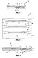
- FIG. 2is a side view of a peripheral side of the optical connector of FIG. 1 .
- FIG. 3is a top plan view of an optical fiber having a tapered end.
- FIG. 3Ais a perspective view of the optical fiber of FIGS. 3 and 4.
- FIG. 4is a cross-sectional side view of the optical fiber of FIG. 3 taken through the core of the fiber.
- FIG. 5is a top plan view of an optical assembly wherein the optical fiber of FIG. 3 is inserted into the optical connector of FIG. 1 .
- FIG. 6is a cross-sectional side view of the left half of the optical assembly of FIG. 5 taken through the core of the fiber and the waveguide of the optical connector.
- FIG. 7is a cross-sectional side view of the optical assembly of FIG. 6 with a cover over the optical fiber and the optical connector.
- FIG. 8is a top plan view of an alternative optical connector for optically connecting three pairs of the optical fibers of FIG. 3 .
- FIG. 9is a cross-sectional side view of an alternative optical assembly wherein a light receiving or transmitting element is in optical communication with the optical fiber through the waveguide of the optical connector.
- FIG. 10is a top plan view of an alternative optical fiber and optical connector.
- FIG. 11is a cross-sectional side view of an optical assembly formed of the optical fiber and optical connector of FIG. 10 .
- FIG. 12is a top plan view of a molded polymeric base for an optical connector.
- FIGS. 1 and 2show an optical connector 10 for optically connecting a pair of optical fibers.
- Optical connector 10includes a base 12 .
- a pair of opposing flared channels, denoted as receiving sections 14are formed in base 12 .
- Receiving sections 14each terminate at an opposite side of a waveguide 16 that extends between and optically connects the receiving sections 14 .
- Waveguide 16is optically accessible through each receiving section 14 .
- Each receiving section 14has an opening 18 at a peripheral side 20 of base 12 .
- Waveguide 16is at an inner end 19 of receiving section 14 distal from side 20 and opposite opening 18 .
- each receiving section 14Moving inward from side 20 of base 12 , each receiving section 14 includes opposing, orthogonal, tapered sidewalls 22 , and a horizontal bottom surface 24 (see FIG. 2) that is perpendicular to opposing sidewalls 22 .
- the opposing sidewalls 22extend diagonally toward each other in the direction of inner end 19 and waveguide 16 , such that receiving section 14 decreases in width from opening 18 to inner end 19 .
- Receiving section 14has a width L 1 between opposing sidewalls 22 at opening 18 , and a smaller width L 2 between opposing sidewalls 22 at inner end 19 .
- Receiving section 14has a vertical depth D 1 between top surface 13 of base 12 and bottom surface 24 of receiving section 14 .
- an exemplary glass optical fiber 40includes a cylindrical central core 42 surrounded by a cylindrical cladding 44 . Light travels in core 42 .
- Optical fiber 40has a first end section 46 that begins near and includes tip 50 .
- the cladding of first end section 46is partially removed, for example, by grinding, etching, or laser ablation.
- the removal of the claddingcreates two opposing orthogonal tapered sidewalls 52 that extend diagonally towards each other in moving from taper boundary 48 toward tip 50 .
- the width of first end section 46 between opposing sidewalls 52decreases from a width equal to the outer diameter of cladding 44 at taper boundary 48 to a width between opposing sidewalls 52 that is slightly larger than the diameter of core 42 at tip 50 .
- first end section 46 of fiber 40is intended to be inserted into receiving section 14 of connector 10
- the width of first end section 46 of fiber 40 between orthogonal sidewalls 52 at taper boundary 48is slightly less than the width L 1 of opening 18 of connector 10
- the width of first end section 46 between sidewalls 52 at tip 50is slightly less than the width L 2 of inner end 19 of receiving section 14
- the length of first end section 46 between taper boundary 48 and tip 50is approximately equal to the length of receiving section 14 between opening 18 and inner end 19 .
- the angle of taper of orthogonal sidewalls 52 of optical fiber 40matches the angle of taper of the orthogonal sidewalls 22 of receiving section 14 of connector 10 .
- first end section 46is partially removed so as to form means for vertically aligning optical fiber 40 in connector 10 .
- cladding 44is removed so as to form opposing tapered bottom and top surfaces 53 and 55 , respectively.
- cladding 44is removed so that tapered bottom and top surfaces 53 and 55 transition into opposing, horizontal bottom and top surfaces 54 and 56 , respectively.
- the height of first end section 46 between bottom and top horizontal surfaces 54 , 56is slightly greater than the diameter of core 42 of optical fiber 40 , and is equal to or slightly less than the depth D 1 of receiving section 14 of connector 10 .
- Tip 50 of optical fiber 40may be flat, or may be ground into a convex or other shape, depending on the application.
- FIG. 5illustrates a self-aligning optical assembly 70 wherein two optical fibers 18 are optically connected to each other through waveguide 16 of optical connector 10 .
- Optical assembly 70is created by inserting the first end section 46 of each optical fiber 40 into opening 18 of one of the receiving sections 14 of connector 10 , and sliding the respective first end section 46 laterally along bottom surface 24 of the receiving section 14 toward inner end 19 and waveguide 16 .
- Optical fiber 40is inserted until the opposing sidewalls 52 of the first end section 46 contact the correspondingly-angled sidewalls 22 of the receiving section 14 of connector 10 . Meanwhile, as shown in FIG.
- the horizontal bottom surface 52 of the first end section 46 of the optical fiber 18rests on the horizontal bottom surface 24 of the receiving section 14 of the connector 10 , and the tip 50 of fiber 40 is at inner end 19 of receiving section 14 immediately adjacent to an orthogonal end surface 17 of waveguide 16 .
- the core 14 of the first end portion 46 of optical fiber 40is positioned for optical communication immediately adjacent to end surface 17 of waveguide 16 of connector 10 with precise three-dimensional alignment.
- an adhesive 71may be used to attach the optical fibers 40 to the abutting surfaces of receiving section 14 of connector 10 and to waveguide 16 .
- the adhesivemay be an optically clear epoxy material.
- the adhesivemay be provided in receiving section 14 before the insertion of optical fiber 40 therein, or may be applied onto optical fiber 40 before such insertion.
- an optically clear adhesivealso is connected between tip 50 and end surface 17 of waveguide 16 .
- a covermay be provided for optical assembly 70 .
- a cover 72rests on top surface 13 of base 12 of connector 10 so as to superimpose and cover the receiving sections 14 , first end section 46 , and waveguide 16 .
- Cover 72may be connected to base 12 by an adhesive, by a hinge, or some other connection means.
- optical connector 10may be made so as to optically connect a plurality of pairs of optical fibers 40 simply by increasing the number of pairs of opposing receiving sections 14 , with each pair having a waveguide 16 between them.
- three pairs of optical fibers 18may be optically connected to connector 75 of FIG. 8, with each pair of fibers 40 being optically connected though a waveguide 16 .
- FIG. 9Another embodiment of an optical assembly within the present invention is shown in FIG. 9 .
- Optical connector 80 of optical assembly 78 of FIG. 9is essentially half of optical connector 10 of FIGS. 1 and 2. That is, one of the receiving ends 14 of connector 10 has been removed to form connector 80 .
- An orthogonal end surface 82 of waveguide 16is exposed at a peripheral side 20 of base 12 .
- a light receiving or transmitting element 84such as a laser diode or a light sensitive circuit (e.g., camera circuit) of a semiconductor chip, is positioned adjacent to the exposed surface 82 of waveguide 16 at peripheral side 20 of base 12 so as to be in optical communication with optical fiber 40 through waveguide 16 .
- FIGS. 10 and 11An alternative embodiment of an optical fiber 86 that may be used with a modified connector 80 (denoted as connector 80 ′) is shown in FIGS. 10 and 11.
- first end section 46has tapered sidewalls 52 (see FIG. 1 ), but retains the curved top and bottom shape of cladding 44 .
- the depth of receiving section 14is approximately the same as the diameter of cladding 44 in this embodiment (see FIG. 11 ), and waveguide 16 would have to made so as to be vertically aligned with core 42 of optical fiber 86 .
- Connectors 10 , 80may be formed of various materials.
- a matrix of bases 12may be formed on a wafer of silicon or gallium arsenide.
- Receiving sections 14may be formed by plasma etching or liquid etching the wafer through a photoresist mask.
- Waveguide 16may be formed by doping the base material, as is conventionally done. Subsequently, individual connectors 10 , 80 are diced from the wafer using a saw.
- base 12may be formed of a moldable polymeric material, as is described in U.S. patent application Ser. No. 09/751537, which is entitled “Tool and Method for Forming an Integrated Optical Circuit, is commonly assigned, was filed with the U.S. Patent and Trademark Office on the same day as or before the present application, and is incorporated herein by reference in its entirety.
- a base 12 with a channel 88 formed thereinmay be formed by compression molding a heated film of thermosetting polymer, thermoplastic, photopolymer, polycarbonate, or some other polymer, using a heated molding die. Subsequently, the patterned film is cured to harden it. Channel 88 has two receiving sections 14 with an empty middle section 90 therebetween.
- the molding die used to form base 12 and channel 88may be made from a silicon or gallium arsenide wafer that is patterned using plasma etching, and then coated with a hard film (e.g., a film of metal, such as nickel) over the patterned surface.
- the molding diemay be mounted on a press or a roller for contacting the heated polymer film.
- the molding diemay be mounted in a cavity mold, and molten polymeric material may be injected into the mold so as to contact the molding die.
- Waveguide 16may be formed by inserting an optically clear moldable polymeric second material into middle section 90 of channel 88 , and then curing the second material.
- Cover 72 of FIG. 7may be a molded polymer material attached to base 12 by an epoxy adhesive.
Landscapes
- Physics & Mathematics (AREA)
- General Physics & Mathematics (AREA)
- Optics & Photonics (AREA)
- Optical Couplings Of Light Guides (AREA)
Abstract
Description
Claims (22)
Priority Applications (1)
| Application Number | Priority Date | Filing Date | Title |
|---|---|---|---|
| US09/751,536US6672773B1 (en) | 2000-12-29 | 2000-12-29 | Optical fiber having tapered end and optical connector with reciprocal opening |
Applications Claiming Priority (1)
| Application Number | Priority Date | Filing Date | Title |
|---|---|---|---|
| US09/751,536US6672773B1 (en) | 2000-12-29 | 2000-12-29 | Optical fiber having tapered end and optical connector with reciprocal opening |
Publications (1)
| Publication Number | Publication Date |
|---|---|
| US6672773B1true US6672773B1 (en) | 2004-01-06 |
Family
ID=29737219
Family Applications (1)
| Application Number | Title | Priority Date | Filing Date |
|---|---|---|---|
| US09/751,536Expired - LifetimeUS6672773B1 (en) | 2000-12-29 | 2000-12-29 | Optical fiber having tapered end and optical connector with reciprocal opening |
Country Status (1)
| Country | Link |
|---|---|
| US (1) | US6672773B1 (en) |
Cited By (54)
| Publication number | Priority date | Publication date | Assignee | Title |
|---|---|---|---|---|
| US20040017962A1 (en)* | 2002-07-26 | 2004-01-29 | Lee Kevin K. | Integrated mode converter, waveguide, and on-chip function |
| US20040116958A1 (en)* | 2001-02-06 | 2004-06-17 | Achim Gopferich | Spacing device for releasing active substances in the paranasal sinus |
| US20060063973A1 (en)* | 2004-04-21 | 2006-03-23 | Acclarent, Inc. | Methods and apparatus for treating disorders of the ear, nose and throat |
| US7031434B1 (en)* | 2003-08-06 | 2006-04-18 | General Electric Company | Method of manufacturing, and a collimator mandrel having variable attenuation characteristics for a CT system |
| US20070129751A1 (en)* | 2004-04-21 | 2007-06-07 | Acclarent, Inc. | Devices, systems and methods useable for treating frontal sinusitis |
| US20070135789A1 (en)* | 2004-04-21 | 2007-06-14 | Acclarent, Inc. | Use of mechanical dilator devices to enlarge ostia of paranasal sinuses and other passages in the ear, nose, throat and paranasal sinuses |
| US20070179518A1 (en)* | 2006-02-02 | 2007-08-02 | Becker Bruce B | Balloon Catheters and Methods for Treating Paranasal Sinuses |
| US20070208252A1 (en)* | 2004-04-21 | 2007-09-06 | Acclarent, Inc. | Systems and methods for performing image guided procedures within the ear, nose, throat and paranasal sinuses |
| US20070249896A1 (en)* | 2004-04-21 | 2007-10-25 | Eric Goldfarb | Endoscopic methods and devices for transnasal procedures |
| US20070282305A1 (en)* | 2004-04-21 | 2007-12-06 | Eric Goldfarb | Endoscopic methods and devices for transnasal procedures |
| US20080125720A1 (en)* | 2006-05-17 | 2008-05-29 | Acclarent, Inc. | Adapter for attaching electromagnetic image guidance components to a medical device |
| US20080195041A1 (en)* | 2004-04-21 | 2008-08-14 | Acclarent, Inc. | Systems and methods for transnasal dilation of passageways in the ear, nose and throat |
| US20080275483A1 (en)* | 2004-04-21 | 2008-11-06 | Acclarent, Inc. | Methods and Apparatus for Treating Disorders of the Ear Nose and Throat |
| US20080287908A1 (en)* | 2004-04-21 | 2008-11-20 | Acclarent, Inc. | Ethmoidotomy System and Implantable Spacer Devices Having Therapeutic Substance Delivery Capability for Treatment of Paranasal Sinusitis |
| US20090005763A1 (en)* | 2004-08-04 | 2009-01-01 | Exploramed Nc1, Inc. | Implantable Devices and Methods for Delivering Drugs and Other Substances to Treat Sinusitis and Other Disorders |
| US20090030409A1 (en)* | 2007-07-27 | 2009-01-29 | Eric Goldfarb | Methods and devices for facilitating visualization in a surgical environment |
| US20090028923A1 (en)* | 2005-01-18 | 2009-01-29 | Acclarent, Inc. | Implantable Devices and Methods for Treating Sinusitis and Other Disorders |
| US20090171301A1 (en)* | 2005-09-23 | 2009-07-02 | Becker Bruce B | Multi-conduit balloon catheter |
| US20090187098A1 (en)* | 2004-04-21 | 2009-07-23 | Acclarent, Inc. | Devices, Systems and Methods for Diagnosing and Treating Sinusitis and Other Disorders of the Ears, Nose, and/or Throat |
| US20090198216A1 (en)* | 2004-04-21 | 2009-08-06 | Acclarent, Inc. | Frontal sinus spacer |
| US20090240112A1 (en)* | 2006-09-15 | 2009-09-24 | Acclarent, Inc. | Methods and Devices for Facilitating Visualization In a Surgical Environment |
| US20090312745A1 (en)* | 2004-04-21 | 2009-12-17 | Acclarent, Inc. | Systems and methods for transnasal dilation of passageways in the ear, nose or throat |
| US20100099946A1 (en)* | 2004-04-21 | 2010-04-22 | Acclarent, Inc. | Methods and apparatus for treating disorders of the ear nose and throat |
| US20100305697A1 (en)* | 2009-03-31 | 2010-12-02 | Acclarent, Inc. | System and Method For Treatment of Non-Ventilating Middle Ear by Providing a Gas Pathway Through the Nasopharynx |
| US7857669B1 (en) | 2009-08-05 | 2010-12-28 | Hamilton Sundstrand Corporation | High power electrical interface connection |
| US20110075976A1 (en)* | 2009-09-30 | 2011-03-31 | James Scott Sutherland | Substrates and grippers for optical fiber alignment with optical element(s) and related methods |
| US20110075132A1 (en)* | 2009-09-30 | 2011-03-31 | James Scott Sutherland | Angle-cleaved optical fibers and methods of making and using same |
| US20110091181A1 (en)* | 2009-10-15 | 2011-04-21 | Demeritt Jeffery A | Coated Optical Fibers and Related Apparatuses, Links, and Methods for Providing Optical Attenuation |
| US20110112512A1 (en)* | 2004-04-21 | 2011-05-12 | Acclarent, Inc. | Devices and methods for treating maxillary sinus disease |
| US20110160740A1 (en)* | 2009-12-28 | 2011-06-30 | Acclarent, Inc. | Tissue Removal in The Paranasal Sinus and Nasal Cavity |
| US8172828B2 (en) | 2004-04-21 | 2012-05-08 | Acclarent, Inc. | Apparatus and methods for dilating and modifying ostia of paranasal sinuses and other intranasal or paranasal structures |
| US8317816B2 (en) | 2002-09-30 | 2012-11-27 | Acclarent, Inc. | Balloon catheters and methods for treating paranasal sinuses |
| US8439687B1 (en) | 2006-12-29 | 2013-05-14 | Acclarent, Inc. | Apparatus and method for simulated insertion and positioning of guidewares and other interventional devices |
| US8485199B2 (en) | 2007-05-08 | 2013-07-16 | Acclarent, Inc. | Methods and devices for protecting nasal turbinate during surgery |
| US8702626B1 (en) | 2004-04-21 | 2014-04-22 | Acclarent, Inc. | Guidewires for performing image guided procedures |
| US20140161400A1 (en)* | 2012-12-10 | 2014-06-12 | Brooks A. Childers | Fiber optic termination arrangement and method of making the same |
| US8764709B2 (en) | 2004-04-21 | 2014-07-01 | Acclarent, Inc. | Devices, systems and methods for treating disorders of the ear, nose and throat |
| US8932276B1 (en) | 2004-04-21 | 2015-01-13 | Acclarent, Inc. | Shapeable guide catheters and related methods |
| US8951225B2 (en) | 2005-06-10 | 2015-02-10 | Acclarent, Inc. | Catheters with non-removable guide members useable for treatment of sinusitis |
| US8979888B2 (en) | 2008-07-30 | 2015-03-17 | Acclarent, Inc. | Paranasal ostium finder devices and methods |
| US9072626B2 (en) | 2009-03-31 | 2015-07-07 | Acclarent, Inc. | System and method for treatment of non-ventilating middle ear by providing a gas pathway through the nasopharynx |
| US9155492B2 (en) | 2010-09-24 | 2015-10-13 | Acclarent, Inc. | Sinus illumination lightwire device |
| US9265407B2 (en) | 2004-04-21 | 2016-02-23 | Acclarent, Inc. | Endoscopic methods and devices for transnasal procedures |
| US9433437B2 (en) | 2013-03-15 | 2016-09-06 | Acclarent, Inc. | Apparatus and method for treatment of ethmoid sinusitis |
| US9615775B2 (en) | 2007-04-30 | 2017-04-11 | Acclarent, Inc. | Methods and devices for ostium measurements |
| US9629684B2 (en) | 2013-03-15 | 2017-04-25 | Acclarent, Inc. | Apparatus and method for treatment of ethmoid sinusitis |
| US9820688B2 (en) | 2006-09-15 | 2017-11-21 | Acclarent, Inc. | Sinus illumination lightwire device |
| US9861793B2 (en) | 2008-03-10 | 2018-01-09 | Acclarent, Inc. | Corewire design and construction for medical devices |
| US10188413B1 (en) | 2004-04-21 | 2019-01-29 | Acclarent, Inc. | Deflectable guide catheters and related methods |
| US10206821B2 (en) | 2007-12-20 | 2019-02-19 | Acclarent, Inc. | Eustachian tube dilation balloon with ventilation path |
| JP2019113703A (en)* | 2017-12-22 | 2019-07-11 | 住友ベークライト株式会社 | Optical waveguide, optical wiring component and electronic apparatus |
| US10524814B2 (en) | 2009-03-20 | 2020-01-07 | Acclarent, Inc. | Guide system with suction |
| US11391892B2 (en)* | 2018-07-12 | 2022-07-19 | Huawei Technologies Co., Ltd. | Optical coupling apparatus, method for packaging optical coupling apparatus, optical module, and communications device |
| US11529502B2 (en) | 2004-04-21 | 2022-12-20 | Acclarent, Inc. | Apparatus and methods for dilating and modifying ostia of paranasal sinuses and other intranasal or paranasal structures |
Citations (24)
| Publication number | Priority date | Publication date | Assignee | Title |
|---|---|---|---|---|
| US3864019A (en) | 1973-11-15 | 1975-02-04 | Bell Telephone Labor Inc | Optical film-fiber coupler |
| US4087158A (en) | 1976-12-06 | 1978-05-02 | The United States Of America As Represented By The Secretary Of The Navy | Low-loss single filament fiber optic connector with three concentric tapered members for each filaments |
| US4262995A (en) | 1979-03-05 | 1981-04-21 | Hughes Aircraft Company | Planar star coupler device for fiber optics |
| US4466696A (en) | 1982-03-29 | 1984-08-21 | Honeywell Inc. | Self-aligned coupling of optical fiber to semiconductor laser or LED |
| US4695124A (en) | 1984-01-30 | 1987-09-22 | The Furukawa Electric Co., Ltd. | Plastic optical fiber cable with ferrule |
| US4735482A (en) | 1984-03-26 | 1988-04-05 | Sumitomo Electric Industries, Ltd. | Device for clamping end portion of optical fiber |
| US4750799A (en) | 1984-08-10 | 1988-06-14 | Nippon Telegraph And Telephone Corporation | Hybrid optical integrated circuit |
| US5011254A (en) | 1989-11-30 | 1991-04-30 | At&T Bell Laboratories | Coupling of optical devices to optical fibers by means of microlenses |
| US5078516A (en) | 1990-11-06 | 1992-01-07 | Bell Communications Research, Inc. | Tapered rib waveguides |
| US5309537A (en) | 1993-04-05 | 1994-05-03 | Motorola, Inc. | Optoelectronic coupling device and method of making |
| US5351331A (en) | 1993-09-17 | 1994-09-27 | Motorola, Inc. | Method and apparatus for splicing optical fibers with signal I/O |
| US5390266A (en)* | 1992-10-05 | 1995-02-14 | Electronic Production Partners Gmbh | Optical element |
| US5404417A (en) | 1989-08-02 | 1995-04-04 | E. I. Du Pont De Nemours And Company | Apparatus for positioning the center of an optical fiber along a predetermined reference axis |
| US5475775A (en) | 1993-01-13 | 1995-12-12 | Robert Bosch Gmbh | Method for producing a hybrid integrated optical circuit and device for emitting light waves |
| US5526454A (en) | 1992-04-10 | 1996-06-11 | Robert Bosch Gmbh | Method for producing optical polymer components having integrated fibre-chip coupling by means of casting technology |
| US5586207A (en) | 1993-11-29 | 1996-12-17 | Northern Telecom Limited | Methods and assemblies for packaging opto-electronic devices and for coupling optical fibers to the packaged devices |
| US5600745A (en) | 1996-02-08 | 1997-02-04 | Industrial Technology Research Institute | Method of automatically coupling between a fiber and an optical waveguide |
| US5708741A (en) | 1995-12-28 | 1998-01-13 | Lucent Technologies Inc. | Method and apparatus for coupling optical fibers to an optical integrated circuit |
| US5815623A (en) | 1996-01-18 | 1998-09-29 | Methode Electronics, Inc. | Optical package with alignment means and method of assembling an optical package |
| US5818994A (en) | 1993-06-18 | 1998-10-06 | Alcatel N.V. | Device for the unadjusted coupling of a number of optical waveguides to a laser array |
| US5845024A (en)* | 1994-09-16 | 1998-12-01 | Namiki Precision Jewel Co., Ltd. | Optical fiber with lens and method of manufacturing the same |
| US6058125A (en) | 1996-01-27 | 2000-05-02 | Nortel Networks Corporation | Semiconductor lasers |
| US6396984B1 (en)* | 1999-01-21 | 2002-05-28 | Samsung Electronics Co., Ltd. | Mode shape converter, method for fabricating the mode shape converter and integrated optical device using the mode shape converter |
| US6496644B1 (en)* | 1998-04-27 | 2002-12-17 | Hamamatsu Photonics K.K. | Optical component having fibers with partitioned cores and production method thereof |
- 2000
- 2000-12-29USUS09/751,536patent/US6672773B1/ennot_activeExpired - Lifetime
Patent Citations (24)
| Publication number | Priority date | Publication date | Assignee | Title |
|---|---|---|---|---|
| US3864019A (en) | 1973-11-15 | 1975-02-04 | Bell Telephone Labor Inc | Optical film-fiber coupler |
| US4087158A (en) | 1976-12-06 | 1978-05-02 | The United States Of America As Represented By The Secretary Of The Navy | Low-loss single filament fiber optic connector with three concentric tapered members for each filaments |
| US4262995A (en) | 1979-03-05 | 1981-04-21 | Hughes Aircraft Company | Planar star coupler device for fiber optics |
| US4466696A (en) | 1982-03-29 | 1984-08-21 | Honeywell Inc. | Self-aligned coupling of optical fiber to semiconductor laser or LED |
| US4695124A (en) | 1984-01-30 | 1987-09-22 | The Furukawa Electric Co., Ltd. | Plastic optical fiber cable with ferrule |
| US4735482A (en) | 1984-03-26 | 1988-04-05 | Sumitomo Electric Industries, Ltd. | Device for clamping end portion of optical fiber |
| US4750799A (en) | 1984-08-10 | 1988-06-14 | Nippon Telegraph And Telephone Corporation | Hybrid optical integrated circuit |
| US5404417A (en) | 1989-08-02 | 1995-04-04 | E. I. Du Pont De Nemours And Company | Apparatus for positioning the center of an optical fiber along a predetermined reference axis |
| US5011254A (en) | 1989-11-30 | 1991-04-30 | At&T Bell Laboratories | Coupling of optical devices to optical fibers by means of microlenses |
| US5078516A (en) | 1990-11-06 | 1992-01-07 | Bell Communications Research, Inc. | Tapered rib waveguides |
| US5526454A (en) | 1992-04-10 | 1996-06-11 | Robert Bosch Gmbh | Method for producing optical polymer components having integrated fibre-chip coupling by means of casting technology |
| US5390266A (en)* | 1992-10-05 | 1995-02-14 | Electronic Production Partners Gmbh | Optical element |
| US5475775A (en) | 1993-01-13 | 1995-12-12 | Robert Bosch Gmbh | Method for producing a hybrid integrated optical circuit and device for emitting light waves |
| US5309537A (en) | 1993-04-05 | 1994-05-03 | Motorola, Inc. | Optoelectronic coupling device and method of making |
| US5818994A (en) | 1993-06-18 | 1998-10-06 | Alcatel N.V. | Device for the unadjusted coupling of a number of optical waveguides to a laser array |
| US5351331A (en) | 1993-09-17 | 1994-09-27 | Motorola, Inc. | Method and apparatus for splicing optical fibers with signal I/O |
| US5586207A (en) | 1993-11-29 | 1996-12-17 | Northern Telecom Limited | Methods and assemblies for packaging opto-electronic devices and for coupling optical fibers to the packaged devices |
| US5845024A (en)* | 1994-09-16 | 1998-12-01 | Namiki Precision Jewel Co., Ltd. | Optical fiber with lens and method of manufacturing the same |
| US5708741A (en) | 1995-12-28 | 1998-01-13 | Lucent Technologies Inc. | Method and apparatus for coupling optical fibers to an optical integrated circuit |
| US5815623A (en) | 1996-01-18 | 1998-09-29 | Methode Electronics, Inc. | Optical package with alignment means and method of assembling an optical package |
| US6058125A (en) | 1996-01-27 | 2000-05-02 | Nortel Networks Corporation | Semiconductor lasers |
| US5600745A (en) | 1996-02-08 | 1997-02-04 | Industrial Technology Research Institute | Method of automatically coupling between a fiber and an optical waveguide |
| US6496644B1 (en)* | 1998-04-27 | 2002-12-17 | Hamamatsu Photonics K.K. | Optical component having fibers with partitioned cores and production method thereof |
| US6396984B1 (en)* | 1999-01-21 | 2002-05-28 | Samsung Electronics Co., Ltd. | Mode shape converter, method for fabricating the mode shape converter and integrated optical device using the mode shape converter |
Non-Patent Citations (1)
| Title |
|---|
| Shiraishi, K.; Yanagi, T.; Kawakami, S., "Light-Propagation Characteristics in Thermally Diffused Expanded Core Fibers," Journal of Lightwave Technology, vol. 11, No. 10, Oct., 1993. |
Cited By (158)
| Publication number | Priority date | Publication date | Assignee | Title |
|---|---|---|---|---|
| US20040116958A1 (en)* | 2001-02-06 | 2004-06-17 | Achim Gopferich | Spacing device for releasing active substances in the paranasal sinus |
| US8740929B2 (en) | 2001-02-06 | 2014-06-03 | Acclarent, Inc. | Spacing device for releasing active substances in the paranasal sinus |
| US6804440B2 (en)* | 2002-07-26 | 2004-10-12 | Lnl Technologies, Inc. | Integrated mode converter, waveguide, and on-chip function |
| US20040017962A1 (en)* | 2002-07-26 | 2004-01-29 | Lee Kevin K. | Integrated mode converter, waveguide, and on-chip function |
| US9457175B2 (en) | 2002-09-30 | 2016-10-04 | Acclarent, Inc. | Balloon catheters and methods for treating paranasal sinuses |
| US8764786B2 (en) | 2002-09-30 | 2014-07-01 | Acclarent, Inc. | Balloon catheters and methods for treating paranasal sinuses |
| US8317816B2 (en) | 2002-09-30 | 2012-11-27 | Acclarent, Inc. | Balloon catheters and methods for treating paranasal sinuses |
| US20080019484A1 (en)* | 2003-08-06 | 2008-01-24 | Rowland Saunders | Method of manufacturing, and a collimator mandrel having variable attenuation characteristics for a ct system |
| US7031434B1 (en)* | 2003-08-06 | 2006-04-18 | General Electric Company | Method of manufacturing, and a collimator mandrel having variable attenuation characteristics for a CT system |
| US7266180B1 (en) | 2003-08-06 | 2007-09-04 | General Electric Company | Method of manufacturing a collimator mandrel having variable attenuation characteristics for a CT system |
| US7436933B2 (en) | 2003-08-06 | 2008-10-14 | General Electric Company | Method of manufacturing, and a collimator mandrel having variable attenuation characteristics for a CT system |
| US8702626B1 (en) | 2004-04-21 | 2014-04-22 | Acclarent, Inc. | Guidewires for performing image guided procedures |
| US9241834B2 (en) | 2004-04-21 | 2016-01-26 | Acclarent, Inc. | Devices, systems and methods for treating disorders of the ear, nose and throat |
| US20080103521A1 (en)* | 2004-04-21 | 2008-05-01 | Acclarent, Inc. | Methods and Apparatus for Treating Disorders of the Ear Nose and Throat |
| US20080119693A1 (en)* | 2004-04-21 | 2008-05-22 | Acclarent, Inc. | Methods and Apparatus for Treating Disorders of the Ear, Nose and Throat |
| US9610428B2 (en) | 2004-04-21 | 2017-04-04 | Acclarent, Inc. | Devices, systems and methods useable for treating frontal sinusitis |
| US20080195041A1 (en)* | 2004-04-21 | 2008-08-14 | Acclarent, Inc. | Systems and methods for transnasal dilation of passageways in the ear, nose and throat |
| US20070249896A1 (en)* | 2004-04-21 | 2007-10-25 | Eric Goldfarb | Endoscopic methods and devices for transnasal procedures |
| US20080275483A1 (en)* | 2004-04-21 | 2008-11-06 | Acclarent, Inc. | Methods and Apparatus for Treating Disorders of the Ear Nose and Throat |
| US20080287908A1 (en)* | 2004-04-21 | 2008-11-20 | Acclarent, Inc. | Ethmoidotomy System and Implantable Spacer Devices Having Therapeutic Substance Delivery Capability for Treatment of Paranasal Sinusitis |
| US9649477B2 (en) | 2004-04-21 | 2017-05-16 | Acclarent, Inc. | Frontal sinus spacer |
| US11957318B2 (en) | 2004-04-21 | 2024-04-16 | Acclarent, Inc. | Methods and apparatus for treating disorders of the ear nose and throat |
| US20060063973A1 (en)* | 2004-04-21 | 2006-03-23 | Acclarent, Inc. | Methods and apparatus for treating disorders of the ear, nose and throat |
| US11864725B2 (en) | 2004-04-21 | 2024-01-09 | Acclarent, Inc. | Devices, systems and methods for diagnosing and treating sinusitis and other disorders of the ears, nose and/or throat |
| US9554691B2 (en) | 2004-04-21 | 2017-01-31 | Acclarent, Inc. | Endoscopic methods and devices for transnasal procedures |
| US20090187098A1 (en)* | 2004-04-21 | 2009-07-23 | Acclarent, Inc. | Devices, Systems and Methods for Diagnosing and Treating Sinusitis and Other Disorders of the Ears, Nose, and/or Throat |
| US20090198216A1 (en)* | 2004-04-21 | 2009-08-06 | Acclarent, Inc. | Frontal sinus spacer |
| US11589742B2 (en) | 2004-04-21 | 2023-02-28 | Acclarent, Inc. | Methods and apparatus for treating disorders of the ear nose and throat |
| US10500380B2 (en) | 2004-04-21 | 2019-12-10 | Acclarent, Inc. | Devices, systems and methods useable for treating sinusitis |
| US20090312745A1 (en)* | 2004-04-21 | 2009-12-17 | Acclarent, Inc. | Systems and methods for transnasal dilation of passageways in the ear, nose or throat |
| US20100099946A1 (en)* | 2004-04-21 | 2010-04-22 | Acclarent, Inc. | Methods and apparatus for treating disorders of the ear nose and throat |
| US20100100181A1 (en)* | 2004-04-21 | 2010-04-22 | Acclarent, Inc. | Devices, systems and methods for diagnosing and treating sinusitus andother disorders of the ears, nose and/or throat |
| US9468362B2 (en) | 2004-04-21 | 2016-10-18 | Acclarent, Inc. | Endoscopic methods and devices for transnasal procedures |
| US20100210901A1 (en)* | 2004-04-21 | 2010-08-19 | Acclarent, Inc. | Devices, Systems and Methods For Diagnosing and Treating Sinusitis and Other Disorders of the Ears, Nose and/or Throat |
| US11511090B2 (en) | 2004-04-21 | 2022-11-29 | Acclarent, Inc. | Devices, systems and methods useable for treating sinusitis |
| US11202644B2 (en) | 2004-04-21 | 2021-12-21 | Acclarent, Inc. | Shapeable guide catheters and related methods |
| US11065061B2 (en) | 2004-04-21 | 2021-07-20 | Acclarent, Inc. | Systems and methods for performing image guided procedures within the ear, nose, throat and paranasal sinuses |
| US11019989B2 (en) | 2004-04-21 | 2021-06-01 | Acclarent, Inc. | Methods and apparatus for treating disorders of the ear nose and throat |
| US11020136B2 (en) | 2004-04-21 | 2021-06-01 | Acclarent, Inc. | Deflectable guide catheters and related methods |
| US10874838B2 (en) | 2004-04-21 | 2020-12-29 | Acclarent, Inc. | Systems and methods for transnasal dilation of passageways in the ear, nose or throat |
| US20110112512A1 (en)* | 2004-04-21 | 2011-05-12 | Acclarent, Inc. | Devices and methods for treating maxillary sinus disease |
| US10856727B2 (en) | 2004-04-21 | 2020-12-08 | Acclarent, Inc. | Endoscopic methods and devices for transnasal procedures |
| US9826999B2 (en) | 2004-04-21 | 2017-11-28 | Acclarent, Inc. | Methods and apparatus for treating disorders of the ear nose and throat |
| US8142422B2 (en) | 2004-04-21 | 2012-03-27 | Acclarent, Inc. | Devices, systems and methods for diagnosing and treating sinusitis and other disorders of the ears, nose and/or throat |
| US8172828B2 (en) | 2004-04-21 | 2012-05-08 | Acclarent, Inc. | Apparatus and methods for dilating and modifying ostia of paranasal sinuses and other intranasal or paranasal structures |
| US20070129751A1 (en)* | 2004-04-21 | 2007-06-07 | Acclarent, Inc. | Devices, systems and methods useable for treating frontal sinusitis |
| US10806477B2 (en) | 2004-04-21 | 2020-10-20 | Acclarent, Inc. | Systems and methods for transnasal dilation of passageways in the ear, nose or throat |
| US20070208252A1 (en)* | 2004-04-21 | 2007-09-06 | Acclarent, Inc. | Systems and methods for performing image guided procedures within the ear, nose, throat and paranasal sinuses |
| US9399121B2 (en) | 2004-04-21 | 2016-07-26 | Acclarent, Inc. | Systems and methods for transnasal dilation of passageways in the ear, nose or throat |
| US8414473B2 (en) | 2004-04-21 | 2013-04-09 | Acclarent, Inc. | Methods and apparatus for treating disorders of the ear nose and throat |
| US8425457B2 (en) | 2004-04-21 | 2013-04-23 | Acclarent, Inc. | Devices, systems and methods for diagnosing and treating sinusitus and other disorder of the ears, nose and/or throat |
| US10779752B2 (en) | 2004-04-21 | 2020-09-22 | Acclarent, Inc. | Guidewires for performing image guided procedures |
| US10702295B2 (en) | 2004-04-21 | 2020-07-07 | Acclarent, Inc. | Methods and apparatus for treating disorders of the ear nose and throat |
| US10695080B2 (en) | 2004-04-21 | 2020-06-30 | Acclarent, Inc. | Devices, systems and methods for diagnosing and treating sinusitis and other disorders of the ears, nose and/or throat |
| US10034682B2 (en) | 2004-04-21 | 2018-07-31 | Acclarent, Inc. | Devices, systems and methods useable for treating frontal sinusitis |
| US9370649B2 (en) | 2004-04-21 | 2016-06-21 | Acclarent, Inc. | Devices, systems and methods useable for treating sinusitis |
| US8715169B2 (en) | 2004-04-21 | 2014-05-06 | Acclarent, Inc. | Devices, systems and methods useable for treating sinusitis |
| US8721591B2 (en) | 2004-04-21 | 2014-05-13 | Acclarent, Inc. | Apparatus and methods for dilating and modifying ostia of paranasal sinuses and other intranasal or paranasal structures |
| US9351750B2 (en) | 2004-04-21 | 2016-05-31 | Acclarent, Inc. | Devices and methods for treating maxillary sinus disease |
| US20070282305A1 (en)* | 2004-04-21 | 2007-12-06 | Eric Goldfarb | Endoscopic methods and devices for transnasal procedures |
| US8747389B2 (en) | 2004-04-21 | 2014-06-10 | Acclarent, Inc. | Systems for treating disorders of the ear, nose and throat |
| US11529502B2 (en) | 2004-04-21 | 2022-12-20 | Acclarent, Inc. | Apparatus and methods for dilating and modifying ostia of paranasal sinuses and other intranasal or paranasal structures |
| US20070135789A1 (en)* | 2004-04-21 | 2007-06-14 | Acclarent, Inc. | Use of mechanical dilator devices to enlarge ostia of paranasal sinuses and other passages in the ear, nose, throat and paranasal sinuses |
| US8764729B2 (en) | 2004-04-21 | 2014-07-01 | Acclarent, Inc. | Frontal sinus spacer |
| US8764709B2 (en) | 2004-04-21 | 2014-07-01 | Acclarent, Inc. | Devices, systems and methods for treating disorders of the ear, nose and throat |
| US8764726B2 (en) | 2004-04-21 | 2014-07-01 | Acclarent, Inc. | Devices, systems and methods useable for treating sinusitis |
| US8777926B2 (en) | 2004-04-21 | 2014-07-15 | Acclarent, Inc. | Apparatus and methods for dilating and modifying ostia of paranasal sinuses and other intranasel or paranasal structures |
| US8852143B2 (en) | 2004-04-21 | 2014-10-07 | Acclarent, Inc. | Devices, systems and methods for treating disorders of the ear, nose and throat |
| US8858586B2 (en) | 2004-04-21 | 2014-10-14 | Acclarent, Inc. | Methods for enlarging ostia of paranasal sinuses |
| US8864787B2 (en) | 2004-04-21 | 2014-10-21 | Acclarent, Inc. | Ethmoidotomy system and implantable spacer devices having therapeutic substance delivery capability for treatment of paranasal sinusitis |
| US8870893B2 (en) | 2004-04-21 | 2014-10-28 | Acclarent, Inc. | Devices, systems and methods for diagnosing and treating sinusitis and other disorders of the ears, nose and/or throat |
| US8894614B2 (en) | 2004-04-21 | 2014-11-25 | Acclarent, Inc. | Devices, systems and methods useable for treating frontal sinusitis |
| US8905922B2 (en) | 2004-04-21 | 2014-12-09 | Acclarent, Inc. | Devices, systems and methods for diagnosing and treating sinusitis and other disorders of the ears, nose and/or throat |
| US8932276B1 (en) | 2004-04-21 | 2015-01-13 | Acclarent, Inc. | Shapeable guide catheters and related methods |
| US8945088B2 (en) | 2004-04-21 | 2015-02-03 | Acclarent, Inc. | Apparatus and methods for dilating and modifying ostia of paranasal sinuses and other intranasal or paranasal structures |
| US9265407B2 (en) | 2004-04-21 | 2016-02-23 | Acclarent, Inc. | Endoscopic methods and devices for transnasal procedures |
| US8961495B2 (en) | 2004-04-21 | 2015-02-24 | Acclarent, Inc. | Devices, systems and methods for treating disorders of the ear, nose and throat |
| US8961398B2 (en) | 2004-04-21 | 2015-02-24 | Acclarent, Inc. | Methods and apparatus for treating disorders of the ear, nose and throat |
| US10631756B2 (en) | 2004-04-21 | 2020-04-28 | Acclarent, Inc. | Guidewires for performing image guided procedures |
| US10492810B2 (en) | 2004-04-21 | 2019-12-03 | Acclarent, Inc. | Devices, systems and methods for diagnosing and treating sinusitis and other disorders of the ears, nose and/or throat |
| US9220879B2 (en) | 2004-04-21 | 2015-12-29 | Acclarent, Inc. | Devices, systems and methods useable for treating sinusitis |
| US10098652B2 (en) | 2004-04-21 | 2018-10-16 | Acclarent, Inc. | Systems and methods for transnasal dilation of passageways in the ear, nose or throat |
| US9167961B2 (en) | 2004-04-21 | 2015-10-27 | Acclarent, Inc. | Methods and apparatus for treating disorders of the ear nose and throat |
| US9055965B2 (en) | 2004-04-21 | 2015-06-16 | Acclarent, Inc. | Devices, systems and methods useable for treating sinusitis |
| US10441758B2 (en) | 2004-04-21 | 2019-10-15 | Acclarent, Inc. | Frontal sinus spacer |
| US10188413B1 (en) | 2004-04-21 | 2019-01-29 | Acclarent, Inc. | Deflectable guide catheters and related methods |
| US9107574B2 (en) | 2004-04-21 | 2015-08-18 | Acclarent, Inc. | Endoscopic methods and devices for transnasal procedures |
| US9089258B2 (en) | 2004-04-21 | 2015-07-28 | Acclarent, Inc. | Endoscopic methods and devices for transnasal procedures |
| US9101384B2 (en) | 2004-04-21 | 2015-08-11 | Acclarent, Inc. | Devices, systems and methods for diagnosing and treating sinusitis and other disorders of the ears, Nose and/or throat |
| US9084876B2 (en) | 2004-08-04 | 2015-07-21 | Acclarent, Inc. | Implantable devices and methods for delivering drugs and other substances to treat sinusitis and other disorders |
| US20090005763A1 (en)* | 2004-08-04 | 2009-01-01 | Exploramed Nc1, Inc. | Implantable Devices and Methods for Delivering Drugs and Other Substances to Treat Sinusitis and Other Disorders |
| US9039657B2 (en) | 2004-08-04 | 2015-05-26 | Acclarent, Inc. | Implantable devices and methods for delivering drugs and other substances to treat sinusitis and other disorders |
| US20100114066A1 (en)* | 2004-08-04 | 2010-05-06 | Acclarent, Inc. | Implantable devices and methods for delivering drugs and other substances to treat sinusitis and other disorders |
| US9039680B2 (en) | 2004-08-04 | 2015-05-26 | Acclarent, Inc. | Implantable devices and methods for delivering drugs and other substances to treat sinusitis and other disorders |
| US20090028923A1 (en)* | 2005-01-18 | 2009-01-29 | Acclarent, Inc. | Implantable Devices and Methods for Treating Sinusitis and Other Disorders |
| US8388642B2 (en) | 2005-01-18 | 2013-03-05 | Acclarent, Inc. | Implantable devices and methods for treating sinusitis and other disorders |
| US9308361B2 (en) | 2005-01-18 | 2016-04-12 | Acclarent, Inc. | Implantable devices and methods for treating sinusitis and other disorders |
| US10842978B2 (en) | 2005-06-10 | 2020-11-24 | Acclarent, Inc. | Catheters with non-removable guide members useable for treatment of sinusitis |
| US8951225B2 (en) | 2005-06-10 | 2015-02-10 | Acclarent, Inc. | Catheters with non-removable guide members useable for treatment of sinusitis |
| US10124154B2 (en) | 2005-06-10 | 2018-11-13 | Acclarent, Inc. | Catheters with non-removable guide members useable for treatment of sinusitis |
| US10639457B2 (en) | 2005-09-23 | 2020-05-05 | Acclarent, Inc. | Multi-conduit balloon catheter |
| US8968269B2 (en) | 2005-09-23 | 2015-03-03 | Acclarent, Inc. | Multi-conduit balloon catheter |
| US9999752B2 (en) | 2005-09-23 | 2018-06-19 | Acclarent, Inc. | Multi-conduit balloon catheter |
| US20090171301A1 (en)* | 2005-09-23 | 2009-07-02 | Becker Bruce B | Multi-conduit balloon catheter |
| US9050440B2 (en) | 2005-09-23 | 2015-06-09 | Acclarent, Inc. | Multi-conduit balloon catheter |
| US20070179518A1 (en)* | 2006-02-02 | 2007-08-02 | Becker Bruce B | Balloon Catheters and Methods for Treating Paranasal Sinuses |
| US9629656B2 (en) | 2006-05-17 | 2017-04-25 | Acclarent, Inc. | Adapter for attaching electromagnetic image guidance components to a medical device |
| US8190389B2 (en) | 2006-05-17 | 2012-05-29 | Acclarent, Inc. | Adapter for attaching electromagnetic image guidance components to a medical device |
| US9198736B2 (en) | 2006-05-17 | 2015-12-01 | Acclarent, Inc. | Adapter for attaching electromagnetic image guidance components to a medical device |
| US20080125720A1 (en)* | 2006-05-17 | 2008-05-29 | Acclarent, Inc. | Adapter for attaching electromagnetic image guidance components to a medical device |
| US9820688B2 (en) | 2006-09-15 | 2017-11-21 | Acclarent, Inc. | Sinus illumination lightwire device |
| US10716629B2 (en) | 2006-09-15 | 2020-07-21 | Acclarent, Inc. | Methods and devices for facilitating visualization in a surgical environment |
| US9603506B2 (en) | 2006-09-15 | 2017-03-28 | Acclarent, Inc. | Methods and devices for facilitating visualization in a surgical environment |
| US9572480B2 (en) | 2006-09-15 | 2017-02-21 | Acclarent, Inc. | Methods and devices for facilitating visualization in a surgical environment |
| US20090240237A1 (en)* | 2006-09-15 | 2009-09-24 | Acclarent Inc. | Methods and Devices for Facilitating Visualization In a Surgical Environment |
| US20090240112A1 (en)* | 2006-09-15 | 2009-09-24 | Acclarent, Inc. | Methods and Devices for Facilitating Visualization In a Surgical Environment |
| US20090030274A1 (en)* | 2006-09-15 | 2009-01-29 | Acclarent, Inc. | Endoscopic methods and devices for transnasal procedures |
| US9179823B2 (en)* | 2006-09-15 | 2015-11-10 | Acclarent, Inc. | Methods and devices for facilitating visualization in a surgical environment |
| US8439687B1 (en) | 2006-12-29 | 2013-05-14 | Acclarent, Inc. | Apparatus and method for simulated insertion and positioning of guidewares and other interventional devices |
| US9615775B2 (en) | 2007-04-30 | 2017-04-11 | Acclarent, Inc. | Methods and devices for ostium measurements |
| US8485199B2 (en) | 2007-05-08 | 2013-07-16 | Acclarent, Inc. | Methods and devices for protecting nasal turbinate during surgery |
| US9463068B2 (en) | 2007-05-08 | 2016-10-11 | Acclarent, Inc. | Methods and devices for protecting nasal turbinates |
| US20090030409A1 (en)* | 2007-07-27 | 2009-01-29 | Eric Goldfarb | Methods and devices for facilitating visualization in a surgical environment |
| US11311419B2 (en) | 2007-12-20 | 2022-04-26 | Acclarent, Inc. | Eustachian tube dilation balloon with ventilation path |
| US10206821B2 (en) | 2007-12-20 | 2019-02-19 | Acclarent, Inc. | Eustachian tube dilation balloon with ventilation path |
| US11850120B2 (en) | 2007-12-20 | 2023-12-26 | Acclarent, Inc. | Eustachian tube dilation balloon with ventilation path |
| US9861793B2 (en) | 2008-03-10 | 2018-01-09 | Acclarent, Inc. | Corewire design and construction for medical devices |
| US8979888B2 (en) | 2008-07-30 | 2015-03-17 | Acclarent, Inc. | Paranasal ostium finder devices and methods |
| US9750401B2 (en) | 2008-07-30 | 2017-09-05 | Acclarent, Inc. | Paranasal ostium finder devices and methods |
| US10271719B2 (en) | 2008-07-30 | 2019-04-30 | Acclarent, Inc. | Paranasal ostium finder devices and methods |
| US11116392B2 (en) | 2008-07-30 | 2021-09-14 | Acclarent, Inc. | Paranasal ostium finder devices and methods |
| US11207087B2 (en) | 2009-03-20 | 2021-12-28 | Acclarent, Inc. | Guide system with suction |
| US10524814B2 (en) | 2009-03-20 | 2020-01-07 | Acclarent, Inc. | Guide system with suction |
| US12303154B2 (en) | 2009-03-20 | 2025-05-20 | Acclarent, Inc. | Guide system with suction |
| US8435290B2 (en) | 2009-03-31 | 2013-05-07 | Acclarent, Inc. | System and method for treatment of non-ventilating middle ear by providing a gas pathway through the nasopharynx |
| US9636258B2 (en) | 2009-03-31 | 2017-05-02 | Acclarent, Inc. | System and method for treatment of non-ventilating middle ear by providing a gas pathway through the nasopharynx |
| US9072626B2 (en) | 2009-03-31 | 2015-07-07 | Acclarent, Inc. | System and method for treatment of non-ventilating middle ear by providing a gas pathway through the nasopharynx |
| US10376416B2 (en) | 2009-03-31 | 2019-08-13 | Acclarent, Inc. | System and method for treatment of non-ventilating middle ear by providing a gas pathway through the nasopharynx |
| US20100305697A1 (en)* | 2009-03-31 | 2010-12-02 | Acclarent, Inc. | System and Method For Treatment of Non-Ventilating Middle Ear by Providing a Gas Pathway Through the Nasopharynx |
| US20110053435A1 (en)* | 2009-08-05 | 2011-03-03 | Wavering Jeffrey T | High power electrical interface connection |
| US7857669B1 (en) | 2009-08-05 | 2010-12-28 | Hamilton Sundstrand Corporation | High power electrical interface connection |
| US8029323B2 (en) | 2009-08-05 | 2011-10-04 | Hamilton Sundstrand Corporation | High power electrical interface connection |
| US20110075976A1 (en)* | 2009-09-30 | 2011-03-31 | James Scott Sutherland | Substrates and grippers for optical fiber alignment with optical element(s) and related methods |
| US20110075132A1 (en)* | 2009-09-30 | 2011-03-31 | James Scott Sutherland | Angle-cleaved optical fibers and methods of making and using same |
| US8477298B2 (en) | 2009-09-30 | 2013-07-02 | Corning Incorporated | Angle-cleaved optical fibers and methods of making and using same |
| US20110091181A1 (en)* | 2009-10-15 | 2011-04-21 | Demeritt Jeffery A | Coated Optical Fibers and Related Apparatuses, Links, and Methods for Providing Optical Attenuation |
| US8295671B2 (en) | 2009-10-15 | 2012-10-23 | Corning Incorporated | Coated optical fibers and related apparatuses, links, and methods for providing optical attenuation |
| US20110160740A1 (en)* | 2009-12-28 | 2011-06-30 | Acclarent, Inc. | Tissue Removal in The Paranasal Sinus and Nasal Cavity |
| US9155492B2 (en) | 2010-09-24 | 2015-10-13 | Acclarent, Inc. | Sinus illumination lightwire device |
| US20140161400A1 (en)* | 2012-12-10 | 2014-06-12 | Brooks A. Childers | Fiber optic termination arrangement and method of making the same |
| WO2014092900A1 (en) | 2012-12-10 | 2014-06-19 | Baker Hughes Incorporated | Fiber optic termination arrangement and method of making the same |
| US9069141B2 (en)* | 2012-12-10 | 2015-06-30 | Baker Hughes Incorporated | Fiber optic termination arrangement and method of making the same |
| EP2929384A4 (en)* | 2012-12-10 | 2016-07-13 | Baker Hughes Inc | FIBER OPTIC TERMINATION ARRANGEMENT AND METHOD FOR MANUFACTURING THE SAME |
| US10524869B2 (en) | 2013-03-15 | 2020-01-07 | Acclarent, Inc. | Apparatus and method for treatment of ethmoid sinusitis |
| US9433437B2 (en) | 2013-03-15 | 2016-09-06 | Acclarent, Inc. | Apparatus and method for treatment of ethmoid sinusitis |
| US9629684B2 (en) | 2013-03-15 | 2017-04-25 | Acclarent, Inc. | Apparatus and method for treatment of ethmoid sinusitis |
| JP2019113703A (en)* | 2017-12-22 | 2019-07-11 | 住友ベークライト株式会社 | Optical waveguide, optical wiring component and electronic apparatus |
| US11391892B2 (en)* | 2018-07-12 | 2022-07-19 | Huawei Technologies Co., Ltd. | Optical coupling apparatus, method for packaging optical coupling apparatus, optical module, and communications device |
Similar Documents
| Publication | Publication Date | Title |
|---|---|---|
| US6672773B1 (en) | Optical fiber having tapered end and optical connector with reciprocal opening | |
| EP0591941B1 (en) | An optical waveguide component and a manufacturing method therefor | |
| US6069991A (en) | Flexible optic connector assembly | |
| US6118917A (en) | Optical fiber passive alignment apparatus using alignment platform | |
| US5790733A (en) | Optoelectronic device receptacle and method of making same | |
| KR100917526B1 (en) | Molds for forming optical connector ferrules, manufacturing method of optical connector ferrules, optical connector ferrules, optical connectors, optical components and optical wiring systems | |
| US6157759A (en) | Optical fiber passive alignment apparatus and method therefor | |
| CA2380240C (en) | Method and device for passive alignment | |
| JPH05210030A (en) | Optically coupled structure and its substrate and method of realizing such a structure | |
| US20170205584A1 (en) | Side-facet coupler having external mounting surface molded to facilitate alignment of optical connections | |
| US5389312A (en) | Method of fabricating molded optical waveguides | |
| JPS6042448B2 (en) | Molding method of optical fiber connector | |
| US5594824A (en) | Coupling device between a glass fiber and a dielectric waveguide | |
| US5500914A (en) | Optical interconnect unit and method or making | |
| US8328436B2 (en) | Optical module | |
| US20030142922A1 (en) | Passive alignment of fiber optic array | |
| US7031576B2 (en) | Connectorized silicon bench for passively aligning optical fibers | |
| US20070189696A1 (en) | Optical board connector assembly | |
| US20040057670A1 (en) | Alignment of fiber optic bundle to array waveguide using pins | |
| EP1004046A1 (en) | Planar optical device connector and method for making same | |
| US6702962B2 (en) | Manufacturing method of ferrule for multi optical connector | |
| EP1223445A1 (en) | Apparatus and method for interconnecting multi-dimensional optical fiber arrays | |
| US5311608A (en) | Molding of optical components using optical fibers to form a mold | |
| US20040001673A1 (en) | Alignment of fiber optic bundle to array waveguide using an epoxy | |
| AU729723C (en) | Planar optical device connector and method for making same |
Legal Events
| Date | Code | Title | Description |
|---|---|---|---|
| AS | Assignment | Owner name:AMKOR TECHNOLOGY, INC., ARIZONA Free format text:ASSIGNMENT OF ASSIGNORS INTEREST;ASSIGNORS:GLENN, THOMAS P.;WEBSTER, STEVEN;REEL/FRAME:011513/0079 Effective date:20010102 | |
| STCF | Information on status: patent grant | Free format text:PATENTED CASE | |
| AS | Assignment | Owner name:CITICORP NORTH AMERICA, INC. AS AGENT, PENNSYLVANI Free format text:SECURITY AGREEMENT;ASSIGNORS:AMKOR TECHNOLOGY, INC.;GUARDIAN ASSETS, INC.;REEL/FRAME:015320/0005 Effective date:20041027 Owner name:CITICORP NORTH AMERICA, INC. AS "AGENT", NEW YORK Free format text:SECURITY AGREEMENT;ASSIGNORS:AMKOR TECHNOLOGY, INC.;GUARDIAN ASSETS, INC.;REEL/FRAME:015942/0521 Effective date:20041027 | |
| AS | Assignment | Owner name:BANK OF AMERICA, N.A., TEXAS Free format text:SECURITY AGREEMENT;ASSIGNOR:AMKOR TECHNOLOGY, INC.;REEL/FRAME:017379/0630 Effective date:20051123 | |
| FPAY | Fee payment | Year of fee payment:4 | |
| FPAY | Fee payment | Year of fee payment:8 | |
| FPAY | Fee payment | Year of fee payment:12 | |
| AS | Assignment | Owner name:BANK OF AMERICA, N.A., AS AGENT, CALIFORNIA Free format text:SECURITY INTEREST;ASSIGNOR:AMKOR TECHNOLOGY, INC.;REEL/FRAME:046683/0139 Effective date:20180713 | |
| AS | Assignment | Owner name:AMKOR TECHNOLOGY SINGAPORE HOLDING PTE.LTD., SINGAPORE Free format text:ASSIGNMENT OF ASSIGNORS INTEREST;ASSIGNOR:AMKOR TECHNOLOGY, INC.;REEL/FRAME:054067/0135 Effective date:20191119 |