US6671934B2 - Retention clip - Google Patents
Retention clipDownload PDFInfo
- Publication number
- US6671934B2 US6671934B2US10/170,485US17048502AUS6671934B2US 6671934 B2US6671934 B2US 6671934B2US 17048502 AUS17048502 AUS 17048502AUS 6671934 B2US6671934 B2US 6671934B2
- Authority
- US
- United States
- Prior art keywords
- retention clip
- leg
- trim piece
- clip according
- vertical axis
- Prior art date
- Legal status (The legal status is an assumption and is not a legal conclusion. Google has not performed a legal analysis and makes no representation as to the accuracy of the status listed.)
- Expired - Lifetime
Links
- 230000014759maintenance of locationEffects0.000titleclaimsabstractdescription120
- 210000002414legAnatomy0.000claimsabstractdescription122
- 210000003127kneeAnatomy0.000claimsabstractdescription14
- 239000000463materialSubstances0.000claimsdescription6
- 229910000639Spring steelInorganic materials0.000claimsdescription3
- 238000009434installationMethods0.000abstractdescription2
- 238000009863impact testMethods0.000description3
- 208000027418Wounds and injuryDiseases0.000description1
- 230000006835compressionEffects0.000description1
- 238000007906compressionMethods0.000description1
- 230000006378damageEffects0.000description1
- 238000006073displacement reactionMethods0.000description1
- 208000014674injuryDiseases0.000description1
- WABPQHHGFIMREM-AHCXROLUSA-Nlead-203Chemical compound[203Pb]WABPQHHGFIMREM-AHCXROLUSA-N0.000description1
- 238000000034methodMethods0.000description1
- 238000011076safety testMethods0.000description1
- 238000009781safety test methodMethods0.000description1
Images


Classifications
- F—MECHANICAL ENGINEERING; LIGHTING; HEATING; WEAPONS; BLASTING
- F16—ENGINEERING ELEMENTS AND UNITS; GENERAL MEASURES FOR PRODUCING AND MAINTAINING EFFECTIVE FUNCTIONING OF MACHINES OR INSTALLATIONS; THERMAL INSULATION IN GENERAL
- F16B—DEVICES FOR FASTENING OR SECURING CONSTRUCTIONAL ELEMENTS OR MACHINE PARTS TOGETHER, e.g. NAILS, BOLTS, CIRCLIPS, CLAMPS, CLIPS OR WEDGES; JOINTS OR JOINTING
- F16B5/00—Joining sheets or plates, e.g. panels, to one another or to strips or bars parallel to them
- F16B5/06—Joining sheets or plates, e.g. panels, to one another or to strips or bars parallel to them by means of clamps or clips
- F16B5/0607—Joining sheets or plates, e.g. panels, to one another or to strips or bars parallel to them by means of clamps or clips joining sheets or plates to each other
- F16B5/0614—Joining sheets or plates, e.g. panels, to one another or to strips or bars parallel to them by means of clamps or clips joining sheets or plates to each other in angled relationship
- Y—GENERAL TAGGING OF NEW TECHNOLOGICAL DEVELOPMENTS; GENERAL TAGGING OF CROSS-SECTIONAL TECHNOLOGIES SPANNING OVER SEVERAL SECTIONS OF THE IPC; TECHNICAL SUBJECTS COVERED BY FORMER USPC CROSS-REFERENCE ART COLLECTIONS [XRACs] AND DIGESTS
- Y10—TECHNICAL SUBJECTS COVERED BY FORMER USPC
- Y10T—TECHNICAL SUBJECTS COVERED BY FORMER US CLASSIFICATION
- Y10T24/00—Buckles, buttons, clasps, etc.
- Y10T24/30—Trim molding fastener
- Y10T24/303—Trim molding fastener having laterally extending biasing appendage
- Y—GENERAL TAGGING OF NEW TECHNOLOGICAL DEVELOPMENTS; GENERAL TAGGING OF CROSS-SECTIONAL TECHNOLOGIES SPANNING OVER SEVERAL SECTIONS OF THE IPC; TECHNICAL SUBJECTS COVERED BY FORMER USPC CROSS-REFERENCE ART COLLECTIONS [XRACs] AND DIGESTS
- Y10—TECHNICAL SUBJECTS COVERED BY FORMER USPC
- Y10T—TECHNICAL SUBJECTS COVERED BY FORMER US CLASSIFICATION
- Y10T24/00—Buckles, buttons, clasps, etc.
- Y10T24/30—Trim molding fastener
- Y10T24/304—Resilient metal type
- Y10T24/307—Sheet metal formed
- Y—GENERAL TAGGING OF NEW TECHNOLOGICAL DEVELOPMENTS; GENERAL TAGGING OF CROSS-SECTIONAL TECHNOLOGIES SPANNING OVER SEVERAL SECTIONS OF THE IPC; TECHNICAL SUBJECTS COVERED BY FORMER USPC CROSS-REFERENCE ART COLLECTIONS [XRACs] AND DIGESTS
- Y10—TECHNICAL SUBJECTS COVERED BY FORMER USPC
- Y10T—TECHNICAL SUBJECTS COVERED BY FORMER US CLASSIFICATION
- Y10T24/00—Buckles, buttons, clasps, etc.
- Y10T24/44—Clasp, clip, support-clamp, or required component thereof
- Y10T24/44017—Clasp, clip, support-clamp, or required component thereof with specific mounting means for attaching to rigid or semirigid supporting structure or structure-to-be-secured
- Y10T24/44026—Clasp, clip, support-clamp, or required component thereof with specific mounting means for attaching to rigid or semirigid supporting structure or structure-to-be-secured for cooperating with aperture in supporting structure or structure-to-be-secured
Definitions
- the present inventionrelates to a fastener, and in particular to a retention clip for securing an interior trim piece to a vehicle.
- Interior trim piecesare usually affixed to the vehicle by a snap-type clip design.
- the snap-type clip designis usually a threaded fastener in the dashboard area that has a visibly exposed sharp edge directly facing the front seat vehicle occupants.
- the visibly exposed sharp edge portion of the fastenerdoes not meet strength and safety testing standards, for example, the direct head impact testing standard.
- a retention clip designhas been used in favor of the snap-type clip design to affix an interior trim piece to the vehicle.
- prior retention clip designshave employed a mirror symmetric configuration (about a central vertical axis, V) with leg portions each extending from a knee portion and having a length, L, and an angle, ⁇ , with respect to the vertical axis, V.
- this conventional designmay not prevent the detachment of the trim piece from the vehicle during certain accident situations. Because the trim piece can become forcibly detached from the vehicle during certain accident situations, such as direct head impact testing, this design can be prone to fail current safety test standards, such as the direct head impact testing standard.
- the inventors of the present inventionhave recognized these and other problems associated with conventional snap-type clip and retention clip designs and have developed a retention clip that can positively secure and lock a trim piece, such as an air deflector housing unit, to the dashboard area of a vehicle.
- the retention clipalso is generally free of any sharp edges that may cause injury to the passenger.
- the retention clip of the inventioncomprises a trim piece affixing portion, a first leg member, and a second leg member that extends from a head portion.
- the trim piece affixing portionis defined by at least one pair of grips that includes a plurality of retention barbs.
- Each first and second leg memberis defined by a first leg portion, an intermediate knee portion, and a second leg portion.
- Each second leg portionis defined by a first and second length and a first and second deployment angle respectively, wherein the first length is greater than the second length.
- Another embodiment of the inventioncomprises a generally U-shaped retention clip fastener that comprises a head portion, a trim piece affixing portion, a first leg member, and a second leg member.
- the trim piece affixing portionextends from the head portion and is defined by at least one pair of grips including a plurality of retention barbs that frictionally engages the trim piece extension member.
- the first and second leg memberswhich extend from the head portion, are defined by a first leg portion, an intermediate knee portion, and a second leg portion.
- the first leg memberprovides a lateral, outboard biasing force on a receiving wall surface of a dashboard.
- the second leg memberwhich is positioned on the outboard side of the trim piece, provides a perpendicular biasing force on the inner contacting surface of the dashboard.
- the first leg portion of the first and second leg membersare symmetrically positioned about a vertical axis located centrally across the head portion.
- the second leg portion of the first and second leg membersare defined by a first and second length respectively and a first and second deployment angle respectively. The first length is greater than the second length and the first deployment angle is greater than the second deployment angle.
- Another embodiment of the inventioncomprises a retention clip for securing a trim piece to a dashboard area of a vehicle.
- the retention clipcomprises means for affixing the retention clip to the trim piece and means for engaging the dashboard area with the retention clip.
- FIG. 1is a perspective view of the retention clip according to an embodiment of the invention
- FIG. 2 ais a front view of a conventional retention clip
- FIG. 2 bis a front view of the retention clip of FIG. 1;
- FIG. 3is a perspective front view of the dashboard assembly and air deflector housing unit
- FIG. 4 ais a perspective rear view of the air deflector housing unit of FIG. 3 prior to the attachment of the retention clip of FIG. 1;
- FIG. 4 bis a perspective rear view of the air deflector housing unit of FIG. 3 after the attachment of the retention clip of FIG. 1;
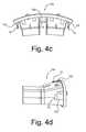
- FIG. 4 cis a top view of the air deflector housing unit of FIG. 4 b;
- FIG. 4 dis a side view of the air deflector housing unit of FIG. 4 b;
- FIG. 5is a cross-sectional view of the retention clip of FIG. 1 attached to the air deflector housing unit taken along line 5 — 5 of FIG. 4 b;
- FIG. 6 ais a cross-sectional view of the air deflector housing unit and retention clip similar to FIG. 5 when the retention clip of the invention is partially inserted into the dashboard area;
- FIG. 6 bis a cross sectional view of the air deflector housing unit and retention clip similar to FIG. 5 when the retention clip of the invention is fully inserted into the dashboard area.
- the retention clip 10is made of lightweight, generally rigid material having suitably resilient characteristics.
- An example of such a material for the retention clip 10is spring steel, or the like.
- the inventionis not limited by the type of material used for the retention clip 10 , and that the invention can be practiced with any suitable material that allows the retention clip 10 to be positioned on the trim piece for subsequent attachment of the trim piece to the vehicle.
- the retention clip 10is first affixed to a trim piece (FIGS. 4 b - 4 d , 5 ), such as an air deflector housing unit 100 , which is then secured to the dashboard area 200 of a vehicle (FIGS. 3, 6 a - 6 b ).
- the retention clip 10is generally defined as having a generally U-shape or V-shape in cross-section and having means for engaging the dashboard area of a vehicle, such as a pair of leg members 12 a , 12 b .
- Each leg member 12 a , 12 bis generally defined as having first leg portions 14 a , 14 b and second leg portions 16 a , 16 b that are further defined by intermediate knee portions 18 a , 18 b .
- the first leg portions 14 a , 14 bextend from a generally rounded base or head portion 20 as the second leg portions 16 a , 16 b extend from the intermediate knee portions 18 a , 18 b , respectively.
- the first leg portions 14 a , 14 b that extend from the head portion 20are shown to be positioned symmetrically about the vertical axis, V, which is referenced from and perpendicular to horizontal axis, A.
- the second leg portions 16 a , 16 bare designed with unique lengths and angles that lock and retain the air deflector housing unit 100 to a dashboard area 200 (FIG. 6 b ).
- Each second leg portion 16 a , 16 bextends from the knee portions 18 a , 18 b , at a predetermined length L 1 , L 2 , and angle ⁇ 1 , ⁇ 2 , with respect to the vertical axis, V, respectively.
- the second leg portion 16 ais defined by a length L 1 and an angle ⁇ 1 .
- the second leg portion 16 bis defined by a length L 2 and an angle ⁇ 2 , which preferably faces the outboard side of the air deflector housing unit 100 .
- Each second leg portion 16 a , 16 bis deployed at selected deployment angles ⁇ 1 and ⁇ 2 that are defined as the angle between the longitudinal lines B 1 , B 2 and dashed lines D, respectively.
- Lines B 1 and B 2are generally shown across the most central portion of the knees 18 a , 18 b , which perpendicularly meet with horizontal axis A.
- One aspect of the inventionis that the length L 1 of the second leg portion 16 a is greater than the length L 2 of the second leg portion 16 b .
- the design of the length L 2may be greater than or equal to zero.
- the angle, ⁇ 1is greater than that of the angle, ⁇ 2 .
- Advantages for the respective lengths L 1 , L 2 and angles ⁇ 1 , ⁇ 2are explained below in FIG. 6 b.
- the air deflector housing unit 100is prepared for assembly to the vehicle by first affixing the retention clips 10 at selected retention clip receiving locations 102 (FIGS. 4 a - 4 d ) before the air deflector housing unit 100 is attached to a “horse-collar” area 201 of the dashboard area 200 at dashboard receiving portions 202 (FIG. 3 ).
- the retention clips 10can be positioned at three receiving locations 102 , such as the left side, right side, and top portion of the air deflector housing unit 100 (FIGS. 4 b - 4 d ).
- the three-point locationprovides added strength as well as the limited movement of the air deflector housing unit 100 once the housing unit 100 is affixed to the dashboard area 200 .
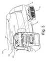
- An electrical connection or hazard control lead 203 for a hazard switchmay extend from the dashboard area 200 and connect to the air deflector housing unit 100 (FIGS. 3, 4 a - 4 b ).
- the retention clip 10is further defined by means for affixing the retention clip 10 to the trim piece, such as a trim piece affixing portion 22 (FIGS. 1, 2 b ).
- the trim piece affixing portion 22is designed to grip each side of a trim piece extension member 104 (FIG. 5) with a pair of grips or legs 24 .
- the trim piece extension 104is located at each receiving location 102 .
- the trim piece affixing portion 22may further include a plurality of retention barbs 26 that may frictionally engage the trim piece extension 104 by gripping or biting into the trim piece extension member 104 .
- the plurality of retention barbs 26may be arranged to be non-perpendicular to the vertical axis, V, to facilitate the gripping or biting into the trim piece extension member 104 .
- the retention barbs 26provide a strengthened relationship of the retention clip 10 and trim piece extension member 104 .
- the trim piece extension member 104may include a plurality of barb receiving portions 106 that provide an increased affixing strength of the retention clip 10 to the trim piece extension member 104 .
- the plurality of barb receiving portions 106are designed to receive the retention barbs 26 , rather than allowing the barbs 26 to simply grip or bite into the trim piece extension member 104 .
- the air deflector housing unit 100is prepared for installation in the dashboard 200 .
- the retention clip 10is affixed to the air deflector housing unit 100 , at each trim piece extension 104 , which generally retains the angles ⁇ 1 , ⁇ 2 when the retention clip 10 is in an “at rest” state.
- the retention clip 10is affixed to the trim piece 100 such that the second leg member 12 b is positioned toward the outboard side of the trim piece 100 .
- the trim piece extension 104causes the trim piece affixing portion 22 to deform outwardly away from the vertical axis, V, while the resilient nature of the retention clip 10 causes the trim piece affixing portion 22 to grip the trim piece extension 104 .
- the deployment angle, ⁇ 1when the retention clip 10 is in the “at rest” state is approximately 15 degrees.
- the second leg portion 16 ais biased inwardly 15 degrees from B 1 toward V.
- the deployment angle, ⁇ 2when the retention clip 10 is in the “at rest” state is approximately 0 degrees.
- the second leg portion 16 bis substantially parallel to the vertical axis, V.
- the retention clip 10is affixed to the trim piece 100 and partially inserted into a receiving wall surface 204 of the dashboard area 200 at one of the dashboard receiving portions 202 .
- the leg members 12 a , 12 bare compressed toward the vertical axis, V.
- the compression of the retention clip 10 by a portion of the receiving wall surface 204causes the deployment angle, ⁇ 1 , of the first leg member 12 a to deform inwardly to approximately 45 degrees with respect to the vertical axis, V.
- the second leg portion 16 ais deformed inwardly an additional 30 degrees from its original “at rest” state deployment angle of approximately 15 degrees toward the vertical axis, V.
- the deployment angle, ⁇ 2of the second leg member 12 b deforms inwardly to approximately 45 degrees with respect to the vertical axis, V.
- the second leg portion 16 bis deformed inwardly approximately 45 degrees from its original “at rest” state deployment angle of approximately 0 degrees toward the vertical axis, V.
- the retention clip 10retains approximately same angular displacement at approximately 45 degrees for deployment angles ⁇ 1 , ⁇ 2 as long as the knee portions 18 a , 18 b contact the receiving wall surface 204 of the dashboard area 200 .
- the knee portions 18 a , 18 bwill eventually no longer engage the receiving wall surface 204 and will enter the area behind the dashboard area 200 so that the retention clip 10 may advantageously lock into place.
- the resilient nature of the retention clip 10causes the deployment angles ⁇ 1 , ⁇ 2 of the second leg portions 16 a , 16 b to move outwardly from the vertical axis, V.
- the second leg portion 16 acomes to rest in a deployment angle of approximately 25 degrees with respect to the vertical axis, V.
- the second leg portion 16 ais deformed inwardly at approximately an additional 10 degrees from its original “at rest” state of approximately 15 degrees with respect to the vertical axis, V.
- the deployment angle, ⁇ 2of the second leg portion 16 b moves outwardly from the vertical axis, V.
- the second leg portion 16 bcomes to rest in a deployment angle of approximately 0 degrees from its original “at rest” state with respect to the vertical axis, V.
- the second leg portion 16 bsubstantially resumes its original “at rest” state deployment angle of approximately 0 degrees with respect to B 2 and the vertical axis, V.
- the a tip 28 of the second leg portion 16 bis substantially perpendicular to the inner contacting surface 206 of the dashboard area 200 and locks the trim piece 100 securely into place.
- the second leg member 12 bcan withstand a higher load in a direction perpendicular to the dashboard area 200 than the first leg member 12 a .
- the second leg portion 16 bexerts a perpendicular biasing force, F P , on the inner surface 206 of the dashboard area 200 when impact forces attempt to push the trim piece 100 away from the dashboard area 200 (i.e. opposite to arrows M shown in FIG. 6 a ).
- first leg member 12 aprovides a lateral, outboard biasing force, F L , to bias the retention clip 10 toward the outboard side of the trim piece 100 .
- F Llateral biasing force
- the first leg member 12 ahelps prevent undesirable lateral movement of the trim piece 100 in the dashboard 200 when impact forces attempt to push the trim piece 100 away from the dashboard area 200 .
Landscapes
- Engineering & Computer Science (AREA)
- General Engineering & Computer Science (AREA)
- Mechanical Engineering (AREA)
- Vehicle Interior And Exterior Ornaments, Soundproofing, And Insulation (AREA)
- Insertion Pins And Rivets (AREA)
Abstract
Description
This application claims the benefit of U.S. Provisional Patent Application No. 60/353,388 filed Feb. 1, 2002.
The present invention relates to a fastener, and in particular to a retention clip for securing an interior trim piece to a vehicle.
Interior trim pieces are usually affixed to the vehicle by a snap-type clip design. The snap-type clip design is usually a threaded fastener in the dashboard area that has a visibly exposed sharp edge directly facing the front seat vehicle occupants. Unfortunately, the visibly exposed sharp edge portion of the fastener does not meet strength and safety testing standards, for example, the direct head impact testing standard.
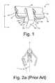
As a result of the fallbacks associated with snap-type clip designs, a retention clip design has been used in favor of the snap-type clip design to affix an interior trim piece to the vehicle. For example, as shown in FIG. 2a, prior retention clip designs have employed a mirror symmetric configuration (about a central vertical axis, V) with leg portions each extending from a knee portion and having a length, L, and an angle, θ, with respect to the vertical axis, V. Although adequate for most applications, this conventional design may not prevent the detachment of the trim piece from the vehicle during certain accident situations. Because the trim piece can become forcibly detached from the vehicle during certain accident situations, such as direct head impact testing, this design can be prone to fail current safety test standards, such as the direct head impact testing standard.
The inventors of the present invention have recognized these and other problems associated with conventional snap-type clip and retention clip designs and have developed a retention clip that can positively secure and lock a trim piece, such as an air deflector housing unit, to the dashboard area of a vehicle. The retention clip also is generally free of any sharp edges that may cause injury to the passenger.
The retention clip of the invention comprises a trim piece affixing portion, a first leg member, and a second leg member that extends from a head portion. The trim piece affixing portion is defined by at least one pair of grips that includes a plurality of retention barbs. Each first and second leg member is defined by a first leg portion, an intermediate knee portion, and a second leg portion. Each second leg portion is defined by a first and second length and a first and second deployment angle respectively, wherein the first length is greater than the second length.
Another embodiment of the invention comprises a generally U-shaped retention clip fastener that comprises a head portion, a trim piece affixing portion, a first leg member, and a second leg member. The trim piece affixing portion extends from the head portion and is defined by at least one pair of grips including a plurality of retention barbs that frictionally engages the trim piece extension member. The first and second leg members, which extend from the head portion, are defined by a first leg portion, an intermediate knee portion, and a second leg portion. The first leg member provides a lateral, outboard biasing force on a receiving wall surface of a dashboard. The second leg member, which is positioned on the outboard side of the trim piece, provides a perpendicular biasing force on the inner contacting surface of the dashboard. The first leg portion of the first and second leg members are symmetrically positioned about a vertical axis located centrally across the head portion. The second leg portion of the first and second leg members are defined by a first and second length respectively and a first and second deployment angle respectively. The first length is greater than the second length and the first deployment angle is greater than the second deployment angle.
Another embodiment of the invention comprises a retention clip for securing a trim piece to a dashboard area of a vehicle. The retention clip comprises means for affixing the retention clip to the trim piece and means for engaging the dashboard area with the retention clip.
The present invention will now be described, by way of example, with reference to the accompanying drawings, in which:
FIG. 1 is a perspective view of the retention clip according to an embodiment of the invention;
FIG. 2ais a front view of a conventional retention clip;
FIG. 2bis a front view of the retention clip of FIG. 1;
FIG. 3 is a perspective front view of the dashboard assembly and air deflector housing unit;
FIG. 4ais a perspective rear view of the air deflector housing unit of FIG. 3 prior to the attachment of the retention clip of FIG. 1;
FIG. 4bis a perspective rear view of the air deflector housing unit of FIG. 3 after the attachment of the retention clip of FIG. 1;
FIG. 4cis a top view of the air deflector housing unit of FIG. 4b;
FIG. 4dis a side view of the air deflector housing unit of FIG. 4b;
FIG. 5 is a cross-sectional view of the retention clip of FIG. 1 attached to the air deflector housing unit taken alongline 5—5 of FIG. 4b;
FIG. 6ais a cross-sectional view of the air deflector housing unit and retention clip similar to FIG. 5 when the retention clip of the invention is partially inserted into the dashboard area;
FIG. 6bis a cross sectional view of the air deflector housing unit and retention clip similar to FIG. 5 when the retention clip of the invention is fully inserted into the dashboard area.
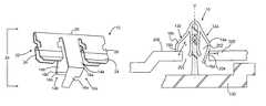
Referring now to FIG. 1, a retention clip, shown generally at10, is illustrated according to an embodiment of the invention. Theretention clip 10 is made of lightweight, generally rigid material having suitably resilient characteristics. An example of such a material for theretention clip 10 is spring steel, or the like. It will be appreciated that the invention is not limited by the type of material used for theretention clip 10, and that the invention can be practiced with any suitable material that allows theretention clip 10 to be positioned on the trim piece for subsequent attachment of the trim piece to the vehicle. In the illustrated embodiment, theretention clip 10 is first affixed to a trim piece (FIGS. 4b-4d,5), such as an airdeflector housing unit 100, which is then secured to thedashboard area 200 of a vehicle (FIGS. 3,6a-6b).
Referring now to FIGS.1 and FIG. 2b, theretention clip 10 is generally defined as having a generally U-shape or V-shape in cross-section and having means for engaging the dashboard area of a vehicle, such as a pair ofleg members leg member first leg portions second leg portions intermediate knee portions first leg portions head portion 20 as thesecond leg portions intermediate knee portions first leg portions head portion 20 are shown to be positioned symmetrically about the vertical axis, V, which is referenced from and perpendicular to horizontal axis, A.
Thesecond leg portions deflector housing unit 100 to a dashboard area200 (FIG. 6b). Eachsecond leg portion knee portions second leg portion 16ais defined by a length L1 and an angle θ1. Thesecond leg portion 16bis defined by a length L2 and an angle θ2, which preferably faces the outboard side of the airdeflector housing unit 100. Eachsecond leg portion knees second leg portion 16ais greater than the length L2 of thesecond leg portion 16b. Depending on the design of thedashboard area 200, the design of the length L2 may be greater than or equal to zero. Preferably, the angle, θ1, is greater than that of the angle, θ2. Advantages for the respective lengths L1, L2 and angles θ1, θ2 are explained below in FIG. 6b.
As seen in FIGS. 3 and 4a-4d, the airdeflector housing unit 100 is prepared for assembly to the vehicle by first affixing the retention clips10 at selected retention clip receiving locations102 (FIGS. 4a-4d) before the airdeflector housing unit 100 is attached to a “horse-collar”area 201 of thedashboard area 200 at dashboard receiving portions202 (FIG.3). For example, the retention clips10 can be positioned at three receivinglocations 102, such as the left side, right side, and top portion of the air deflector housing unit100 (FIGS. 4b-4d). Although other clip receiving locations are contemplated, the three-point location provides added strength as well as the limited movement of the airdeflector housing unit 100 once thehousing unit 100 is affixed to thedashboard area 200. An electrical connection orhazard control lead 203 for a hazard switch may extend from thedashboard area 200 and connect to the air deflector housing unit100 (FIGS. 3,4a-4b).
To assist in affixing theretention clip 10 to the airdeflector housing unit 100, theretention clip 10 is further defined by means for affixing theretention clip 10 to the trim piece, such as a trim piece affixing portion22 (FIGS. 1,2b). The trimpiece affixing portion 22 is designed to grip each side of a trim piece extension member104 (FIG. 5) with a pair of grips orlegs 24. Thetrim piece extension 104 is located at each receivinglocation 102. The trimpiece affixing portion 22 may further include a plurality ofretention barbs 26 that may frictionally engage thetrim piece extension 104 by gripping or biting into the trimpiece extension member 104. The plurality ofretention barbs 26 may be arranged to be non-perpendicular to the vertical axis, V, to facilitate the gripping or biting into the trimpiece extension member 104. In addition, theretention barbs 26 provide a strengthened relationship of theretention clip 10 and trimpiece extension member 104. Alternatively, the trimpiece extension member 104 may include a plurality ofbarb receiving portions 106 that provide an increased affixing strength of theretention clip 10 to the trimpiece extension member 104. The plurality ofbarb receiving portions 106 are designed to receive theretention barbs 26, rather than allowing thebarbs 26 to simply grip or bite into the trimpiece extension member 104. Regarding of using either the plurality ofbarbs 26 or the plurality ofbarb receiving portions 106, when thehead portion 20 contacts atop portion 108 of the trimpiece extension member 104, the airdeflector housing unit 100 is prepared for installation in thedashboard 200.
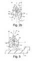
As shown in FIG. 5, theretention clip 10 is affixed to the airdeflector housing unit 100, at eachtrim piece extension 104, which generally retains the angles θ1, θ2 when theretention clip 10 is in an “at rest” state. Here, theretention clip 10 is affixed to thetrim piece 100 such that thesecond leg member 12bis positioned toward the outboard side of thetrim piece 100. Thetrim piece extension 104 causes the trimpiece affixing portion 22 to deform outwardly away from the vertical axis, V, while the resilient nature of theretention clip 10 causes the trimpiece affixing portion 22 to grip thetrim piece extension 104. Referring also to FIG. 2b, the deployment angle, θ1, when theretention clip 10 is in the “at rest” state is approximately 15 degrees. In other words, thesecond leg portion 16ais biased inwardly 15 degrees from B1 toward V. The deployment angle, θ2, when theretention clip 10 is in the “at rest” state is approximately 0 degrees. In other words, thesecond leg portion 16bis substantially parallel to the vertical axis, V. Although the first andsecond leg members piece affixing portion 22 is affixed to and securely grips the trimpiece extension member 104.
As shown in FIG. 6a, theretention clip 10 is affixed to thetrim piece 100 and partially inserted into a receivingwall surface 204 of thedashboard area 200 at one of thedashboard receiving portions 202. As theretention clip 10 is inserted into the receivingwall surface 204, theleg members retention clip 10 by a portion of the receivingwall surface 204 causes the deployment angle, θ1, of thefirst leg member 12ato deform inwardly to approximately 45 degrees with respect to the vertical axis, V. In other words, thesecond leg portion 16ais deformed inwardly an additional 30 degrees from its original “at rest” state deployment angle of approximately 15 degrees toward the vertical axis, V. Likewise, the deployment angle, θ2, of thesecond leg member 12bdeforms inwardly to approximately 45 degrees with respect to the vertical axis, V. In other words, thesecond leg portion 16bis deformed inwardly approximately 45 degrees from its original “at rest” state deployment angle of approximately 0 degrees toward the vertical axis, V.
Theretention clip 10, as explained above, retains approximately same angular displacement at approximately 45 degrees for deployment angles θ1, θ2 as long as theknee portions wall surface 204 of thedashboard area 200. As theretention clip 10 andtrim piece 100 is completely inserted into thedashboard receiving portion 202 in the direction shown by the arrows M, theknee portions wall surface 204 and will enter the area behind thedashboard area 200 so that theretention clip 10 may advantageously lock into place.
As seen in FIG. 6b, once theretention clip 10 is fully inserted into thedashboard receiving portion 202, the resilient nature of theretention clip 10 causes the deployment angles θ1, θ2 of thesecond leg portions second leg portion 16acomes to rest in a deployment angle of approximately 25 degrees with respect to the vertical axis, V. In other words, thesecond leg portion 16ais deformed inwardly at approximately an additional 10 degrees from its original “at rest” state of approximately 15 degrees with respect to the vertical axis, V. Likewise, the deployment angle, θ2, of thesecond leg portion 16bmoves outwardly from the vertical axis, V. However, thesecond leg portion 16bcomes to rest in a deployment angle of approximately 0 degrees from its original “at rest” state with respect to the vertical axis, V. In other words, thesecond leg portion 16bsubstantially resumes its original “at rest” state deployment angle of approximately 0 degrees with respect to B2 and the vertical axis, V. Thus, the a tip28 of thesecond leg portion 16bis substantially perpendicular to the inner contactingsurface 206 of thedashboard area 200 and locks thetrim piece 100 securely into place. As a result, thesecond leg member 12bcan withstand a higher load in a direction perpendicular to thedashboard area 200 than thefirst leg member 12a. Thus, thesecond leg portion 16bexerts a perpendicular biasing force, FP, on theinner surface 206 of thedashboard area 200 when impact forces attempt to push thetrim piece 100 away from the dashboard area200 (i.e. opposite to arrows M shown in FIG. 6a).
In addition, thesecond leg portion 16aoffirst leg member 12aprovides a lateral, outboard biasing force, FL, to bias theretention clip 10 toward the outboard side of thetrim piece 100. As a result of the lateral biasing force, FL, thefirst leg member 12ahelps prevent undesirable lateral movement of thetrim piece 100 in thedashboard 200 when impact forces attempt to push thetrim piece 100 away from thedashboard area 200.
It should be understood that various alternatives to the embodiments of the invention described herein may be employed in practicing the invention. It is intended that the following claims define the scope of the invention and that the method and apparatus within the scope of these claims and their equivalents be covered thereby.
Claims (34)
1. A retention clip for securing a trim piece to a vehicle, comprising:
a head portion;
a first leg member that extends from the head portion; and
a second leg member that extends from the head portion,
wherein a length of one of the first and second leg members is greater than a length of the other one of the first and second leg members, and
wherein a leg portion of the first and second leg members define a first and second deployment angle with respect to a vertical axis centrally located across the head portion, respectively, and
wherein the first deployment angle is greater than the second deployment angle.
2. The retention clip according toclaim 1 , wherein the retention clip is made from a spring steel material.
3. The retention clip according toclaim 1 , wherein a first leg portion of the first and second leg members are symmetrically positioned about a vertical axis centrally located across the head portion.
4. The retention clip according toclaim 1 , wherein the first deployment angle is approximately 15 degrees with respect to the vertical axis when the retention clip is in an at rest state.
5. The retention clip according toclaim 1 , wherein the second deployment angle is approximately 0 degrees with respect to the vertical axis when the retention clip is in an at rest state.
6. The retention clip according toclaim 1 , wherein a second leg member is positioned on an outboard side of the trim piece.
7. The retention clip according toclaim 1 , wherein a second leg portion of the first leg member is further defined by a deployment angle that is approximately 25 degrees with respect to a vertical axis centrally located across the head portion when the retention clip is fully inserted into the trim piece.
8. The retention clip according toclaim 1 , wherein a second leg portion of the second leg member is further defined by a deployment angle that is approximately 0 degrees with respect to a vertical axis centrally located across the head portion when the retention clip is fully inserted into the trim piece.
9. The retention clip according toclaim 1 , wherein the first leg member provides a lateral, outboard biasing force when the retention clip is fully inserted into the trim piece.
10. The retention clip according toclaim 1 , wherein the second leg member provides a perpendicular biasing force when the retention clip is fully inserted in the trim piece.
11. The retention clip according toclaim 1 , wherein each of the first and second leg members include a first and second leg portion, and wherein a length of one of the first and second leg portions is approximately greater than or equal to zero.
12. The retention clip according toclaim 1 , further comprising a trim piece affixing portion that extends from the head portion defined by at least one pair of grips including a plurality of retention barbs.
13. A generally U-shaped retention clip for securing an air deflector housing unit to a dashboard area of a vehicle, the air deflector housing unit comprising a trim piece extension member, wherein the trim piece extension member is defined by retention clip receiving locations that correlate to the left, right, and top portion of the air deflector housing unit, the dashboard area defined by an inner contacting surface and a receiving wall surface, comprising:
a head portion;
a first leg member that provides a lateral, outboard biasing force on the receiving wall surface of the dashboard, wherein the first leg member extends from the head portion, wherein the first leg member is defined by a first leg portion, an intermediate knee portion, and a second leg portion having a length; and
a second leg member positioned on the outboard side of the trim piece that provides a perpendicular biasing force on the inner contacting surface of the dashboard, wherein the second leg member extends from the head portion, wherein the second leg member is defined by a first leg portion, an intermediate knee portion, and a second leg portion having a length,
wherein the first leg portion of the first and second leg members are symmetrically positioned about a vertical axis located centrally across the head portion, wherein the second leg portion of the first and second leg members are define a first and second deployment angle, respectively, and
wherein the length of the first leg portion is greater than the length of the second leg portion, and
wherein the first deployment angle is greater than the second deployment angle.
14. The retention clip according toclaim 13 , wherein the first deployment angle is approximately 15 degrees with respect to the vertical axis.
15. The retention clip according toclaim 13 , wherein the second deployment angle is approximately 0 degrees with respect to the vertical axis.
16. The retention clip according toclaim 13 , wherein the second leg portion of the first leg member is further defined by a deployment angle that is approximately 25 degrees with respect to the vertical axis.
17. The retention clip according toclaim 13 , wherein the second leg portion of the second leg member is further defined by a deployment angle that is approximately 0 degrees with respect to the vertical axis.
18. The retention clip according toclaim 13 , wherein the length of one of the first and second leg portions is approximately greater than or equal to zero.
19. The retention clip according toclaim 13 , further comprising a trim piece affixing portion that extends from the head portion, wherein the trim piece affixing portion is defined by at least one pair of grips including a plurality of retention barbs that frictionally engages the trim piece extension member.
20. A retention clip for securing a trim piece to a dashboard area of a vehicle, comprising:
means for affixing the retention clip to the trim piece; and
means for engaging the dashboard area with the retention clip to positively secure the trim piece to the dashboard area of the vehicle,
wherein said engaging means comprises first and second deployment angles with respect to the vertical axis centrally located across said affixing means respectively, and
wherein the first deployment angle is greater than the second deployment angle.
21. The retention clip according toclaim 20 , wherein said affixing means comprises a trim piece affixing portion that extends from a head portion defined by at least one pair of grips including a plurality of retention barbs.
22. A retention clip for securing a trim piece to a vehicle, comprising:
a head portion;
a first leg member that extends from the head portion; and
a second leg member that extends from the head portion,
wherein a leg portion of the first and second leg members define a first and second deployment angle with respect to a vertical axis centrally located across the head portion, respectively, and
wherein the first deployment angle is greater than the second deployment angle.
23. The retention clip according toclaim 22 , wherein the first leg member is defined by a first leg portion, an intermediate knee portion, and a second leg portion having a length, and
wherein the second leg member is defined by a first leg portion, an intermediate knee portion, and a second leg portion having a length.
24. The retention clip according toclaim 22 , wherein the retention clip is made from a spring steel material.
25. The retention clip according toclaim 22 , wherein a first leg portion of the first and second leg members are symmetrically positioned about a vertical axis centrally located across the head portion.
26. The retention clip according toclaim 22 , wherein the first deployment angle is approximately 15 degrees with respect to the vertical axis when the retention clip is in an at rest state.
27. The retention clip according toclaim 22 , wherein the second deployment angle is approximately 0 degrees with respect to the vertical axis when the retention clip is in an at rest state.
28. The retention clip according toclaim 22 , wherein a second leg member is positioned on an outboard side of the trim piece.
29. The retention clip according toclaim 22 , wherein a second leg portion of the first leg member is further defined by a deployment angle that is approximately 25 degrees with respect to a vertical axis centrally located across the head portion when the retention clip is fully inserted into the trim piece.
30. The retention clip according toclaim 22 , wherein a second leg portion of the second leg member is further defined by a deployment angle that is approximately 0 degrees with respect to a vertical axis centrally located across the head portion when the retention clip is fully inserted into the trim piece.
31. The retention clip according toclaim 22 , wherein the first leg member provides a lateral, outboard biasing force when the retention clip is fully inserted into the trim piece.
32. The retention clip according toclaim 22 , wherein the second leg member provides a perpendicular biasing force when the retention clip is fully inserted in the trim piece.
33. The retention clip according toclaim 22 , wherein each of the first and second leg members include a first and second leg portion, and wherein a length of one of the first and second leg portions is approximately greater than or equal to zero.
34. The retention clip according toclaim 22 , further comprising a trim piece affixing portion that extends from the head portion defined by at least one pair of grips including a plurality of retention barbs.
Priority Applications (1)
| Application Number | Priority Date | Filing Date | Title |
|---|---|---|---|
| US10/170,485US6671934B2 (en) | 2002-02-01 | 2002-06-13 | Retention clip |
Applications Claiming Priority (2)
| Application Number | Priority Date | Filing Date | Title |
|---|---|---|---|
| US35338802P | 2002-02-01 | 2002-02-01 | |
| US10/170,485US6671934B2 (en) | 2002-02-01 | 2002-06-13 | Retention clip |
Publications (2)
| Publication Number | Publication Date |
|---|---|
| US20030145438A1 US20030145438A1 (en) | 2003-08-07 |
| US6671934B2true US6671934B2 (en) | 2004-01-06 |
Family
ID=27663202
Family Applications (1)
| Application Number | Title | Priority Date | Filing Date |
|---|---|---|---|
| US10/170,485Expired - LifetimeUS6671934B2 (en) | 2002-02-01 | 2002-06-13 | Retention clip |
Country Status (2)
| Country | Link |
|---|---|
| US (1) | US6671934B2 (en) |
| CA (1) | CA2415819A1 (en) |
Cited By (12)
| Publication number | Priority date | Publication date | Assignee | Title |
|---|---|---|---|---|
| US20050028328A1 (en)* | 2002-08-01 | 2005-02-10 | Lowry Joseph William | Spring fastener having stabilizing barbs |
| US20070044279A1 (en)* | 2005-08-29 | 2007-03-01 | Attax | Resilient fastener for fixing two parts onto each other |
| US20070186389A1 (en)* | 2001-06-25 | 2007-08-16 | Smith Michael W | Four legged fastener clip |
| US20080235921A1 (en)* | 2007-03-28 | 2008-10-02 | Zwier Daniel G | Landscape edging clip |
| US20080271297A1 (en)* | 2007-04-26 | 2008-11-06 | Dominique Dubost | System for fixing two components to each other |
| US20090102217A1 (en)* | 2007-10-19 | 2009-04-23 | Honda Motor Co., Ltd. | Clip tower for energy absorption |
| US20100005695A1 (en)* | 2008-07-08 | 2010-01-14 | Hannspree, Inc. | Display device and spring structure thereof |
| US20100006163A1 (en)* | 2008-01-25 | 2010-01-14 | Vitec. LLC | Fuel System and Method for Assembling the Same |
| US7762574B1 (en) | 2009-06-02 | 2010-07-27 | Toyota Motor Engineering & Manufacturing North America, Inc. | Trim panel assembly |
| US20110131918A1 (en)* | 2009-12-09 | 2011-06-09 | Jerrold Scott Glynn | Serviceable Trim Panel With Integral Fastener |
| US8584426B2 (en) | 2010-06-04 | 2013-11-19 | Milgard Manufacturing Incorporated | Sash binder |
| US10351030B2 (en)* | 2017-09-14 | 2019-07-16 | Ford Global Technologies, Llc | Seat trim retention system with asymmetrical retention force |
Families Citing this family (3)
| Publication number | Priority date | Publication date | Assignee | Title |
|---|---|---|---|---|
| US6848874B2 (en)* | 2002-06-14 | 2005-02-01 | Joseph William Lowry | Spring fastener having multifunctional barbs |
| TW200623980A (en)* | 2004-12-31 | 2006-07-01 | Tatung Co Ltd | Springy contact |
| DE102017004100A1 (en) | 2017-04-28 | 2018-10-31 | A. Raymond Et Cie | Clip for supporting a first component on a second component |
Citations (20)
| Publication number | Priority date | Publication date | Assignee | Title |
|---|---|---|---|---|
| US2264228A (en)* | 1940-11-04 | 1941-11-25 | Carl J Wagner | Guard or rub rail |
| US2708779A (en)* | 1954-07-12 | 1955-05-24 | Sound Inc | Cover clip |
| US2837184A (en)* | 1956-01-26 | 1958-06-03 | Fernberg Eric Birger | Beading fastener |
| US2981387A (en)* | 1958-08-18 | 1961-04-25 | Gen Motors Corp | Clip |
| US3382615A (en)* | 1966-03-04 | 1968-05-14 | Adell Robert | Ornamental and protective molding for motor vehicle doors |
| US3977048A (en)* | 1975-09-15 | 1975-08-31 | Usm Corporation | Molding clips |
| US4247585A (en) | 1979-06-04 | 1981-01-27 | Mccord Corporation | Automotive body assembly (fascia support wire) |
| US4663210A (en)* | 1983-10-11 | 1987-05-05 | Dr. Ing. H.C.F. Porsche Aktiengesellschaft | Paneling member for the interior of automotive vehicles, especially a dashboard |
| US5084944A (en)* | 1991-02-01 | 1992-02-04 | Budd R. Brothers | Universal material clip |
| US5288121A (en) | 1993-02-25 | 1994-02-22 | Grant Industries, Inc. | Automobile trim strip and carpet retaining clip |
| US5347690A (en) | 1992-12-15 | 1994-09-20 | Ford Motor Company | Fastener apparatus for an automotive body panel component |
| US5526553A (en) | 1994-10-24 | 1996-06-18 | Unisys Corporation | Snap-lock spring clip attachment system |
| US5803532A (en) | 1996-12-17 | 1998-09-08 | General Motors Corporation | Energy absorbing molding assembly |
| US5846631A (en)* | 1994-11-30 | 1998-12-08 | Nicholas Plastics, Inc. | Molding |
| US5934729A (en) | 1997-03-10 | 1999-08-10 | Ford Global Technologies, Inc. | Energy-absorbing fastener system |
| US6049952A (en) | 1998-09-10 | 2000-04-18 | Chrysler Corporation | Energy absorbing trim component fastening system |
| US6101686A (en) | 1998-03-17 | 2000-08-15 | Daimlerchrysler Corporation | Interior trim spring clip |
| US6119316A (en) | 1996-06-03 | 2000-09-19 | Daiwa Kasei Kogyo Kabushiki Kaisha | Fastener |
| US6132154A (en) | 1998-07-30 | 2000-10-17 | Easter; Robert Leslie | Instrument panel retention fixing device |
| US6220645B1 (en) | 1997-02-05 | 2001-04-24 | Becker Group Europe Gmbh | Device for screwless mounting of an accessory |
- 2002
- 2002-06-13USUS10/170,485patent/US6671934B2/ennot_activeExpired - Lifetime
- 2003
- 2003-01-08CACA002415819Apatent/CA2415819A1/ennot_activeAbandoned
Patent Citations (20)
| Publication number | Priority date | Publication date | Assignee | Title |
|---|---|---|---|---|
| US2264228A (en)* | 1940-11-04 | 1941-11-25 | Carl J Wagner | Guard or rub rail |
| US2708779A (en)* | 1954-07-12 | 1955-05-24 | Sound Inc | Cover clip |
| US2837184A (en)* | 1956-01-26 | 1958-06-03 | Fernberg Eric Birger | Beading fastener |
| US2981387A (en)* | 1958-08-18 | 1961-04-25 | Gen Motors Corp | Clip |
| US3382615A (en)* | 1966-03-04 | 1968-05-14 | Adell Robert | Ornamental and protective molding for motor vehicle doors |
| US3977048A (en)* | 1975-09-15 | 1975-08-31 | Usm Corporation | Molding clips |
| US4247585A (en) | 1979-06-04 | 1981-01-27 | Mccord Corporation | Automotive body assembly (fascia support wire) |
| US4663210A (en)* | 1983-10-11 | 1987-05-05 | Dr. Ing. H.C.F. Porsche Aktiengesellschaft | Paneling member for the interior of automotive vehicles, especially a dashboard |
| US5084944A (en)* | 1991-02-01 | 1992-02-04 | Budd R. Brothers | Universal material clip |
| US5347690A (en) | 1992-12-15 | 1994-09-20 | Ford Motor Company | Fastener apparatus for an automotive body panel component |
| US5288121A (en) | 1993-02-25 | 1994-02-22 | Grant Industries, Inc. | Automobile trim strip and carpet retaining clip |
| US5526553A (en) | 1994-10-24 | 1996-06-18 | Unisys Corporation | Snap-lock spring clip attachment system |
| US5846631A (en)* | 1994-11-30 | 1998-12-08 | Nicholas Plastics, Inc. | Molding |
| US6119316A (en) | 1996-06-03 | 2000-09-19 | Daiwa Kasei Kogyo Kabushiki Kaisha | Fastener |
| US5803532A (en) | 1996-12-17 | 1998-09-08 | General Motors Corporation | Energy absorbing molding assembly |
| US6220645B1 (en) | 1997-02-05 | 2001-04-24 | Becker Group Europe Gmbh | Device for screwless mounting of an accessory |
| US5934729A (en) | 1997-03-10 | 1999-08-10 | Ford Global Technologies, Inc. | Energy-absorbing fastener system |
| US6101686A (en) | 1998-03-17 | 2000-08-15 | Daimlerchrysler Corporation | Interior trim spring clip |
| US6132154A (en) | 1998-07-30 | 2000-10-17 | Easter; Robert Leslie | Instrument panel retention fixing device |
| US6049952A (en) | 1998-09-10 | 2000-04-18 | Chrysler Corporation | Energy absorbing trim component fastening system |
Cited By (21)
| Publication number | Priority date | Publication date | Assignee | Title |
|---|---|---|---|---|
| US20070186389A1 (en)* | 2001-06-25 | 2007-08-16 | Smith Michael W | Four legged fastener clip |
| US7444721B2 (en)* | 2001-06-25 | 2008-11-04 | Termax Corporation | Four legged fastener clip |
| US7572089B2 (en)* | 2002-08-01 | 2009-08-11 | Termax Corporation | Spring fastener having stabilizing barbs |
| US20050028328A1 (en)* | 2002-08-01 | 2005-02-10 | Lowry Joseph William | Spring fastener having stabilizing barbs |
| US20070044279A1 (en)* | 2005-08-29 | 2007-03-01 | Attax | Resilient fastener for fixing two parts onto each other |
| US7415752B2 (en)* | 2005-08-29 | 2008-08-26 | Attax | Resilient fastener for fixing two parts onto each other |
| US8056195B2 (en)* | 2007-03-28 | 2011-11-15 | Permaloc Corporation | Landscape edging clip |
| US20080235921A1 (en)* | 2007-03-28 | 2008-10-02 | Zwier Daniel G | Landscape edging clip |
| US20080271297A1 (en)* | 2007-04-26 | 2008-11-06 | Dominique Dubost | System for fixing two components to each other |
| US8152405B2 (en)* | 2007-04-26 | 2012-04-10 | Attax | System for fixing two components to each other |
| US20090309389A1 (en)* | 2007-10-19 | 2009-12-17 | Honda Motor Co., Ltd. | Clip tower for energy absorption |
| US20090102217A1 (en)* | 2007-10-19 | 2009-04-23 | Honda Motor Co., Ltd. | Clip tower for energy absorption |
| US7600809B2 (en)* | 2007-10-19 | 2009-10-13 | Honda Motor Co., Ltd. | Clip tower for energy absorption |
| US8276979B2 (en) | 2007-10-19 | 2012-10-02 | Honda Motor Co., Ltd. | Clip tower for energy absorption |
| US20100006163A1 (en)* | 2008-01-25 | 2010-01-14 | Vitec. LLC | Fuel System and Method for Assembling the Same |
| US20100005695A1 (en)* | 2008-07-08 | 2010-01-14 | Hannspree, Inc. | Display device and spring structure thereof |
| US7762574B1 (en) | 2009-06-02 | 2010-07-27 | Toyota Motor Engineering & Manufacturing North America, Inc. | Trim panel assembly |
| US20110131918A1 (en)* | 2009-12-09 | 2011-06-09 | Jerrold Scott Glynn | Serviceable Trim Panel With Integral Fastener |
| US8528295B2 (en) | 2009-12-09 | 2013-09-10 | Johnson Controls Technology Company | Serviceable trim panel with integral fastener |
| US8584426B2 (en) | 2010-06-04 | 2013-11-19 | Milgard Manufacturing Incorporated | Sash binder |
| US10351030B2 (en)* | 2017-09-14 | 2019-07-16 | Ford Global Technologies, Llc | Seat trim retention system with asymmetrical retention force |
Also Published As
| Publication number | Publication date |
|---|---|
| CA2415819A1 (en) | 2003-08-01 |
| US20030145438A1 (en) | 2003-08-07 |
Similar Documents
| Publication | Publication Date | Title |
|---|---|---|
| US6671934B2 (en) | Retention clip | |
| US5377949A (en) | Breakaway accessory mounting for vehicles | |
| US5458365A (en) | Adjustable snap away fastener | |
| US7077449B2 (en) | Mounting structure of a vehicle interior part | |
| US7530600B2 (en) | Temporary hold mechanism for a buckle assembly | |
| KR101496369B1 (en) | Seatbelt anchor assembly | |
| US6049952A (en) | Energy absorbing trim component fastening system | |
| US6176660B1 (en) | Releasable fastener with lateral stabilizing brace members and latch legs carrying fastener insertion guide | |
| JP2008020006A (en) | High fixing strength fixture | |
| US20110219588A1 (en) | Attachment structure of clip and mounting-subject member | |
| JPH07144646A (en) | Safety steering mechanism for automobiles, especially passenger cars | |
| US11590894B2 (en) | Device for mounting an inside rear-view mirror in a vehicle, and vehicle comprising such a mounting arrangement | |
| US6659519B2 (en) | Supplemental rear bumper and method | |
| US20010002084A1 (en) | Steering wheel with a driver airbag module | |
| JP2002166774A (en) | Footrest clip and footrest device | |
| JPH08200333A (en) | Fixing clip for automobile interior trim part | |
| JPH1130214A (en) | clip | |
| WO2014137773A1 (en) | Clip assembly | |
| US6131241A (en) | Carpet locator and retaining system | |
| US20010022440A1 (en) | Assembly, in particular gas bag module | |
| JP2001278071A (en) | Steering column support device | |
| CN211501212U (en) | Improved safety air bag buckle | |
| CN212243267U (en) | Automobile pre-tightening end piece assembly | |
| JP3641719B2 (en) | Assist grip mounting structure | |
| JP2975261B2 (en) | Vehicle component mounting members |
Legal Events
| Date | Code | Title | Description |
|---|---|---|---|
| AS | Assignment | Owner name:INTIER AUTOMOTIVE INC., CANADA Free format text:ASSIGNMENT OF ASSIGNORS INTEREST;ASSIGNORS:WENZLICK, STANLEY J.;KORNYLO, WALTER P.;REEL/FRAME:013007/0887 Effective date:20020304 | |
| STCF | Information on status: patent grant | Free format text:PATENTED CASE | |
| FPAY | Fee payment | Year of fee payment:4 | |
| FPAY | Fee payment | Year of fee payment:8 | |
| FPAY | Fee payment | Year of fee payment:12 | |
| AS | Assignment | Owner name:MAGNA SEATING INC., CANADA Free format text:CHANGE OF NAME;ASSIGNOR:INTIER AUTOMOTIVE INC.;REEL/FRAME:036474/0448 Effective date:20080630 | |
| AS | Assignment | Owner name:GRUPO ANTOLIN-IRAUSA, S.A., SPAIN Free format text:ASSIGNMENT OF ASSIGNORS INTEREST;ASSIGNOR:MAGNA SEATING INC;REEL/FRAME:037901/0452 Effective date:20150831 |