US6671310B1 - Method and apparatus for positioning pulses over time by applying time-hopping codes having pre-defined characteristics - Google Patents
Method and apparatus for positioning pulses over time by applying time-hopping codes having pre-defined characteristicsDownload PDFInfo
- Publication number
- US6671310B1 US6671310B1US09/591,690US59169000AUS6671310B1US 6671310 B1US6671310 B1US 6671310B1US 59169000 AUS59169000 AUS 59169000AUS 6671310 B1US6671310 B1US 6671310B1
- Authority
- US
- United States
- Prior art keywords
- time
- code
- hopping
- technique
- transmission system
- Prior art date
- Legal status (The legal status is an assumption and is not a legal conclusion. Google has not performed a legal analysis and makes no representation as to the accuracy of the status listed.)
- Expired - Lifetime, expires
Links
Images


Classifications
- H—ELECTRICITY
- H04—ELECTRIC COMMUNICATION TECHNIQUE
- H04B—TRANSMISSION
- H04B1/00—Details of transmission systems, not covered by a single one of groups H04B3/00 - H04B13/00; Details of transmission systems not characterised by the medium used for transmission
- H04B1/69—Spread spectrum techniques
- H04B1/7163—Spread spectrum techniques using impulse radio
- H04B1/7176—Data mapping, e.g. modulation
- H—ELECTRICITY
- H04—ELECTRIC COMMUNICATION TECHNIQUE
- H04J—MULTIPLEX COMMUNICATION
- H04J13/00—Code division multiplex systems
- H04J13/0074—Code shifting or hopping
- H—ELECTRICITY
- H04—ELECTRIC COMMUNICATION TECHNIQUE
- H04J—MULTIPLEX COMMUNICATION
- H04J13/00—Code division multiplex systems
- H04J13/10—Code generation
- H—ELECTRICITY
- H04—ELECTRIC COMMUNICATION TECHNIQUE
- H04L—TRANSMISSION OF DIGITAL INFORMATION, e.g. TELEGRAPHIC COMMUNICATION
- H04L25/00—Baseband systems
- H04L25/38—Synchronous or start-stop systems, e.g. for Baudot code
- H04L25/40—Transmitting circuits; Receiving circuits
- H04L25/49—Transmitting circuits; Receiving circuits using code conversion at the transmitter; using predistortion; using insertion of idle bits for obtaining a desired frequency spectrum; using three or more amplitude levels ; Baseband coding techniques specific to data transmission systems
- H04L25/4902—Pulse width modulation; Pulse position modulation
- H—ELECTRICITY
- H04—ELECTRIC COMMUNICATION TECHNIQUE
- H04B—TRANSMISSION
- H04B1/00—Details of transmission systems, not covered by a single one of groups H04B3/00 - H04B13/00; Details of transmission systems not characterised by the medium used for transmission
- H04B1/69—Spread spectrum techniques
- H04B2001/6908—Spread spectrum techniques using time hopping
Definitions
- the present inventionrelates to impulse transmission systems and, more particularly, to a method of applying time-hopping codes for time positioning of pulses in an impulse transmission system.
- TM-UWBTime Modulated Ultra Wideband
- impulse radio systemswere first described in a series of patents, including U.S. Pat. No. 4,641,317 (issued Feb. 3, 1987), U.S. Pat. No. 4,813,057 (issued Mar. 14, 1989), U.S. Pat. No. 4,979,186 (issued Dec. 18, 1990), and U.S. Pat. No.
- Multiple access impulse radio systemsare radically different from conventional Code Division Multiple Access (CDMA), Time Division Multiple Access (TDMA) and Frequency Division Multiple Access (FDMA) systems.
- CDMACode Division Multiple Access
- TDMATime Division Multiple Access
- FDMAFrequency Division Multiple Access
- a conventional impulse radio transmitteremits a low power electromagnetic train of short pulses, which are shaped to approach a Gaussian monocycle.
- the impulse radio transmitteruses very little power to generate noise-like communication signals for use in multiple-access communications, radar and positioning applications, among other things.
- the impulse radio systemsdepend, in part, on processing gain to achieve rejection of unwanted signals. Because of the extremely high achievable processing gains, the impulse radio systems are relatively immune to unwanted signals and interference, which limit the performance of systems that use continuous sinusoidal waveforms.
- the high processing gains of the impulse radio systemsalso provide much higher dynamic ranges than those commonly achieved by the processing gains of other known spread-spectrum systems.
- Impulse radio communication systemstransmit and receive the pulses at precisely controlled time intervals, in accordance with a time-hopping code.
- the time-hopping codedefines a communication channel that can be considered as a unidirectional data path for communicating information at high speed.
- typical impulse radio transmittersuse position modulation, which is a form of time modulation, to position the pulses in time, based on instantaneous samples of a modulating information signal.
- the modulating information signalmay for example be a multi-state information signal, such as a binary signal.
- a modulatorvaries relative positions of a plurality of pulses on a pulse-by-pulse basis, in accordance with the modulating information signal and a specific time-hopping code that defines the communication channel.
- each binary statemay modulate the time position of more than one pulse to generate a modulated, coded timing signal that comprises a train of identically shaped pulses that represent a single data bit.
- the impulse transmitterapplies the generated pulses to a specified transmission medium, via a coupler, such as an antenna, which electromagnetically radiates the pulses for reception by an impulse radio receiver.
- the impulse radio receivertypically includes a single direct conversion stage. Using a correlator, the conversion stage coherently converts the received pulses to a baseband signal, based on a priori knowledge of the time-hopping code.
- the correlatorintegrates the desired received pulses coherently, while the undesired noise signals are integrated non-coherently such that by comparing the coherent and non-coherent integration results, the impulse receiver can recover the communicated information.
- SS-CDMAspread-spectrum code division multiple access
- Direct sequence CDMA systemsemploy pseudo-noise (PN) codewords generated at a transmitter to “spread” the bandwidth occupied by transmitted data beyond the minimum required by the data.
- PNpseudo-noise
- the conventional SS-CDMA systemsemploy a family of orthogonal or quasi-orthogonal spreading codes, with a pilot spreading code sequence synchronized to the family of codes. Each user is assigned one of the spreading codes as a spreading function.
- PNpseudo-noise
- the time-hopping code for impulse radio communicationsis not necessary for energy spreading, because the monocycle pulses themselves have an inherently wide bandwidth. Instead, the impulse radio systems use the time-hoping codes for channelization, energy smoothing in the frequency domain, and interference suppression.
- the time-hoping codedefines a relative position of each pulse within a group of pulses, or pulse train, such that the combination of pulse positions defines the communications channel.
- each state of a multi-state information signalvaries a relative pulse position by a predefined time shift such that a modulated, coded timing signal is generated comprising a train of pulses, each with timing corresponding to the combination of the time position coding and the multi-state modulation.
- pulsesare time-modulated forward or backward about a nominal position. More specifically, each pulse is time modulated by adjusting its position within a time frame to one of two or more possible times. For example, in order to send a “0” binary bit during the time frame, the pulse may be offset from a nominal position of the time frame by about ⁇ 50 pico-seconds. For a “1” binary state, the pulse may be offset from the nominal position by about +50 pico-seconds.
- Conventional coders that generate the time-hoping codedo so in response to a periodic timing signal that corresponds to the data-rate of the multi-state information signal.
- the data rate of the impulse radio transmissionmay for example be a fraction of a periodic timing signal that is used as a time base or time reference.
- decoding errorsare minimized using distinctive time-hopping codes with suitable autocorrelation and cross-correlation properties.
- the cross-correlation between any two time-hopping codesshould be low for minimal interference between multiple users in a communications system or between multiple target reflections in radar and positioning applications.
- the autocorrelation property of a time-hoping codeshould be steeply peaked, with small side-lobes. Maximally peaked time-hopping code autocorrelation yields optimal acquisition and synchronization properties for communications, radar and positioning applications.
- coding schemeswith known correlation characteristics are available. For example, algebraic codes, Quadratic Congruential (QC) codes, Hyperbolic Congruential (HC) codes and optical codes have been suggested in the past for coding in impulse radio systems.
- the coding schemesguarantee a maximum number of pulse coincidences, i.e., hits, for any defined time frame or time frame shift during which the codes are repeated.
- HC codesare guaranteed a maximum of two hits for any sub-frame or frame shift.
- McCorkle in U.S. Pat. No. 5,847,677discloses a random number generator for generating a pseudo-random code for use with jittered pulse repetition interval radar systems.
- the codeis generated by a random number generator that possesses certain attributes desirable for a jittered radar. As disclosed, the attributes related to a flat frequency spectrum, a nearly perfect spike for an autocorrelation function, a controllable absolute minimum and maximum interval, long sequences that do not repeat, and a reasonable average pulse rate.
- a super-framecorresponds to a time interval of about 1 millisecond, representing one repetition of a code pattern, where as a frame is defined as a time interval of about 1 microsecond divided according to a code length.
- a sub-framecorresponds to a short time interval of about 1 nano second during which a pulse is time positioned.
- TM-UWB technologymay be used in a wide variety of applications, such as multiple-access communication systems, positioning systems, radar systems, etc. Such applications have varying requirements for correlation and spectral properties of the pulse trains they employ.
- the described time-hopping code methodsproduce codes that can be employed to address either a spectral property requirement or a correlation property requirement of given application, but are limited in their ability to address both correlation and spectral property requirements. As a result, such codes are limited in their ability to address both signal acquisition and channelization requirements of a given TM-UWB application requiring tradeoffs to be made when selecting a time-hopping code. Because of the wide variety of TM-UWB technology applications and limitations to current time-hopping code generation and mapping methods, there exists a need for code generation and mapping methods that satisfy correlation property and spectral property requirements of TM-UWB applications.
- a sequential and/or nested combination of two or more time-hopping codesis used to specify pulse positions in time such that the correlation and/or spectral properties of the combined codes are realized.
- the present inventionprovides a method for positioning of pulses over time that specifies a time layout that is subdivided into at least a first and a second time components.
- the present inventionapplies a first time-hopping code having first pre-defined properties to the first time component, and applies a second time-hopping code having second pre-defined properties to the second time component.
- the first time-hopping codemay be generated using a numerical code generation technique, for example, one with nearly ideal autocorrelation properties.
- the numerical code generation techniquecan include Welch-Costas Array, Golomb-Costas Array, or Hyperbolic Congruential code generation techniques.
- the second time-hopping codemay also be generated using a numerical code generation technique, for example, one with nearly ideal cross-correlation properties.
- the numerical code generation techniquecan include Quadratic Congruential, Linear Congruential, or Hyperbolic Congruential code generation techniques.
- the first and second time componentsmay have the same or different sizes.
- the time layoutis sequentially subdivided into a first or a second subdivision time components.
- the first and second subdivision time componentscan have the same or different sizes.
- the first and second time componentsmay contain discrete time values.
- the discrete time valuescan be evenly distributed or non-evenly distributed within the time components.
- the first and second time componentsmay be sequentially subdivided into at least a first or a second subdivision time component containing discrete time values.
- the first and second subdivision time componentscan have the same or different sizes.
- the discrete time valuescan be evenly distributed or non-evenly distributed within the subdivision time components.
- the first and second pre-defined propertiesmay relate to a spectral property or a correlation property, such as an auto-correlation property or a cross-correlation property.
- a spectral property or a correlation propertysuch as an auto-correlation property or a cross-correlation property.
- the first and second pre-defined propertiesmay relate to different spectral and correlation properties.
- the first predefined propertiesmay relate to the auto-correlation properties and the second predefined properties may relate to the cross-correlation properties.
- the first or second time-hopping codeis generated using a numerical code generation technique with nearly ideal spectral properties.
- the numerical code generation techniquecan include linear congruential pseudorandom number generator, additive lagged-Fibonacci pseudorandom number generator, linear feedback shift register, lagged-Fibonacci shift register, chaotic code generator or optimal Golomb ruler code generator techniques.
- the first time-hopping codespecifies subdivision time components within which pulses are to be placed and the second time-hopping code specifies discrete time positions within the subdivision time components specified by the first time-hopping code.
- first and second time-hopping codesare mapped to the first time component, and first and second time-hopping codes are mapped to the second time component, where each first time-hopping code specifies subdivision time components within which pulses are to be placed and each second time-hopping code specifies discrete time positions within the subdivision time components specified by the corresponding first time-hopping code.
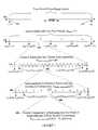
- FIG. 1illustrates a time period including exemplary time period layout parameters, and exemplary subdivisions of the time period including frames, subcomponents, smaller time components and even smaller time components;
- FIG. 2 aillustrates a discrete value layout of thirty-seven evenly distributed values including exemplary layout parameters
- FIG. 2 billustrates a discrete value layout of six non-evenly distributed values including exemplary layout parameters
- FIG. 3illustrates a combined value range/discrete value layout of four frames subdivided into nine subcomponents containing 27 discrete time values each including exemplary layout parameters;
- FIG. 4illustrates a code mapping approach, depicting pulses mapped to subcomponents based on integer code element values of a time-hopping code, where an integer code element exists per frame and pulses are positioned within subcomponents using a common position offset;
- FIG. 5illustrates a code mapping approach, depicting pulses mapped to discrete time values based on integer code element values of a time-hopping code, where an integer code element exists per frame;
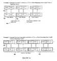
- FIG. 6illustrates a sequential combination of two or more repeating codes and a repeating sequential combination of two or more repeating codes
- FIG. 7 aillustrates mapping of a sequential combination of two or more repeating same length codes to a repeating layout and mapping of a repeating sequential combination of two or more repeating same length codes to a repeating layout;
- FIG. 7 billustrates mapping a sequential combination of two or more repeating codes of different sizes to a sequential combination of two or more repeating layouts of different sizes and mapping a repeating sequential combination of two or more repeating codes of different sizes to a repeating sequential combination of two or more repeating layouts of different sizes;
- FIG. 8illustrates multicast transmissions between a transmitter and four receivers using a sequential combination or repeating sequential combination of four repeating codes
- FIG. 9illustrates use of a sequential combination of an optimal code for signal acquisition and an optimal code for channelization
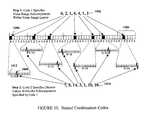
- FIG. 10illustrates use of a first code to specify subcomponents within a value range layout and a second code to specify discrete values within the subcomponents specified by the first code
- FIG. 11illustrates the effect on the spectrum of a quadratic congruential code resulting from the use of a nested pseudorandom code
- FIG. 12illustrates a sequential combination of two or more repeating nested codes and a repeating sequential combination of two or more repeating nested codes.
- FIG. 13 ais a diagram of a binary linear feedback shift-register pseudorandom number generator
- FIG. 13 bis a diagram of an additive Lagged-Fibonacci shift register pseudorandom number generator
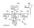
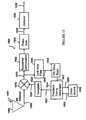
- FIG. 14is a block diagram of an impulse transmitter that advantageously uses the present invention.
- FIG. 15is a block diagram of an impulse receiver that advantageously uses the present invention.
- the present inventionprovides a method of using a generated code to specify positions of pulses within a pulse train for use in an impulse radio transmission system.
- each generated codeconsists of a set or a number of code element values.
- the methodinvolves defining one or more layouts of time periods over which the pulse train is overlaid, generating two or more time-hopping codes with pre-defined properties, and mapping the codes to the time layout(s).
- a combination of codesare mapped to sequential layouts.
- a combination of codesare nested such that one code specifies subcomponents within a layout while the second code specifies discrete time values within the subcomponents specified by the first code.
- a combination of nested codesare mapped to sequential layouts.
- a sequence of pulses known as a pulse trainis transmitted and received over a period of time such that the relative positioning of the pulses in time defines a channel used by the system to transmit information.
- Time period(s)can be laid out in a multitude of ways to accommodate a wide variety of pulse transmission system applications.
- One approachinvolves a value range layout where a period of time is divided into smaller and smaller components. The division is used to achieve a desired component resolution in order to facilitate mapping of a code element value to a time position value that resides within a layout component, which corresponds to some range of time values.
- FIG. 1illustrates an exemplary component based time period value range layout 102 of time position values between a minimum value of t 0 at 110 , and a maximum value of t max at 112 .
- the layout 102may include frames 104 .
- Frames 104may include subcomponents 106 .
- Subcomponents 106may include smaller components 108 , which in turn may include even smaller components. The process can be repeated, ad infinitum, so that smaller and smaller components can be obtained.
- Multiple frame sizesmay be employed to accommodate multiple data stream systems, to add an encryption dimension, and/or for many other purposes.
- one or more acquisition frames and/or one or more header framescan be intermixed with one or more frames containing user data, wherein the acquisition, header, and user data frames have different sizes.
- same size framesmay be employed such that acquisition, header, and user data are combined into a single data stream that is deciphered via a communications protocol once the data stream is captured.
- the number and size of frames used in a given layoutcan also be tailored to meet specific application requirements. They can also be used to remain within system implementation limits, to achieve one or more of a variety of system characteristics in areas such as performance (i.e., bit rate), reliability (i.e., bit error rate), system-simplicity, ease-of-use, etc., and/or for many other reasons.
- minimum and maximum time valuesare specified for each frame 104 .
- the minimum time value for a given frame, t min (n)may equal the maximum time value of the preceding frame, t max (n ⁇ 1), or t 0 ( 110 ).
- the maximum time value of a given frame, t max (n)may equal the minimum time value for the following frame, t min (n+1), or t max ( 112 ).
- the time periodis evenly divided such that t max (n) ⁇ t min (n) is equal for each frame n.
- N framesAn array of layout parameters, N subcomponents (N frames ), can be specified to subdivide frames into subcomponents.
- subcomponent sizesmay be employed to accommodate multiple bit rates, to achieve desirable correlation properties, to add an encryption dimension, and/or for many other purposes, as will be recognized by persons skilled in the art.
- the number and size of subcomponents for a given frame used in a given layoutcan also be tailored to meet specific application requirements. These parameters may also be selected to remain within system implementation limits, to achieve one or more of a variety of system characteristics in areas such as performance (i.e., bit rate), reliability (i.e., bit error rate), system-simplicity, ease-of-use, etc., and/or for many other reasons.
- minimum and maximum time valuesare specified for each subcomponent 106 (m) of each frame 104 (n).
- the minimum time value for a given subcomponent, t min (n,m)may equal the maximum time value of the preceding subcomponent, t max (n,m ⁇ 1), or the minimum time value of the frame in which the subcomponent resides, t min (n).
- the maximum time value of a given subcomponent, t max (n,m)may alternatively equal the minimum time value for the following subcomponent, t min (n,m+1), or the maximum time value of the frame in which the subcomponent resides, t max (n)
- framesmay be evenly divided.
- t max (n,m) ⁇ t min (n,m)may be equal for each subcomponent 106 of a frame 104 or for all frames 104 such that all subcomponents of a given frame 104 are of the same size.
- the subcomponent sizesmay vary from frame to frame or all subcomponents of all frames may be the same size depending on the sizes of the frames and the numbers of subcomponents within the frames.
- additional multi-dimensional arrays of layout parameterscan be used to further subdivide subcomponents into smaller components 108 of the same or different sizes, ad infinitum. This subdivision may continue until a smallest desirable time component resolution is attained.
- the number and size of these smaller time components 108can also be tailored to meet specific application requirements. These parameters can also be tailored to remain within system implementation limits, to achieve one or more of a variety of system characteristics in areas such as performance (i.e., bit rate), reliability (i.e., bit error rate), system-simplicity, ease-of-use, etc., and/or for many other reasons.
- minimum and maximum time valuesare specified for each time component (a).
- the minimum time value for a component, t min (n,m, . . . , a)may be equal to the maximum time value of the preceding component, t max (n,m, . . .
- t min(n,m, . . . ).
- the maximum time value of a given time component, t max (n,m, . . . , a)may alternatively be equal to the minimum time value for the following component, t min (n,m, . . . , a+1), or the maximum time value of the next higher level time component in which the time component resides, t max (n,m, . . . ).
- next higher-level componentsWhen same-sized smaller time components are employed, the next higher-level components may be evenly divided. Consequently, t max (n,m, . . . , a) ⁇ t min (n,m, . . . , a) may be equal for each time component of a given next higher level component. For all next higher-level components, all time components of a given next higher-level component may be of the same or different size.
- the time component sizesmay vary from next higher-level component to next higher-level component.
- all time components of all higher level componentsmay be of the same size, depending on the sizes of the next higher level components and the numbers of time components in the next higher level components.
- a time period of length t maxis depicted such that the time period is bounded by endpoints of t 0 ( 110 ) and t max ( 112 ).
- the time periodis subdivided into four frames 104 by setting the layout parameter N frames to a value of four (4).
- the frameis subdivided into twenty subcomponents 106 by setting the layout parameter N subcomponents (2) to a value of twenty (20).
- the subcomponent 106is subdivided into ten smaller time components 108 by setting the layout parameter N smaller—components (2,8) to a value of ten (10).
- Discrete time valuesmay be evenly distributed or not as depicted in the two figures.
- the discrete value layout approachcan be combined with a value range layout approach, enabling code element values to specify a component within a value range layout and a discrete value within the component.
- FIG. 3The use of a combination of these two layout approaches is shown in FIG. 3 .
- a time value range layout 300is subdivided into four frames 302 that are subdivided into nine subcomponents 304 containing 27 discrete time values 306 each.
- a time-hopping codeis comprised of code elements whose values map pulses to time positions within the defined layout.
- the numbering scheme used for a codemust be consistent with the numbering scheme used for the defined time period layout to allow mapping of code element values to layout components or discrete positions within the layout.
- Components or discrete valuesmay be numbered beginning with zero, one, or with any other number.
- Components produced by subdividing higher level components, such as subcomponents or smaller time period components,may be numbered per higher level component such that subcomponent numbering begins again with each higher level component, or may be numbered in sequence independent of the higher level component in which they reside.
- an established offset valuecan be used to specify the exact position of the pulse within the frame, subcomponent, or smaller time period component to which a code element value is mapped.
- FIGS. 4 and 5illustrate mapping of time-hopping codes to a value range layout and to a discrete value range layout, respectively.
- the figuredepicts mapping of code element values 402 to subcomponents 406 numbered per frame 404 .
- an integer code elementexists per each frame.
- Pulses 408are shown positioned in the approximate center of the subcomponents 406 to which code elements 402 are mapped as specified using a position offset value.
- FIG. 5shows mapping of code element values to discrete time values within a combined value range/discrete value layout, where an integer code element exists per frame. Instead of being mapped inside of the subcomponents as in FIG. 4, in FIG. 5 the code element values 502 are mapped as pulses 508 to discrete values 506 within frames 504 .
- the present inventionprovides several approaches for using two or more codes to specify time positions of pulses. Combinations of two or more codes can be used, for example, to address correlation and/or spectral properties of different TM-UWB applications.
- FIG. 6provides two examples of this sequential combination codes approach.
- a first code 602is shown repeating until some event 604 occurs, at which time the impulse transmission system employs a second code 606 .
- the second code 606is then shown repeating thereafter. It is further shown that the system may transition to additional codes as necessary.
- a sequential combination of two or more codesis shown repeating. For example, whole sequences of multiple codes 608 , 610 (each multiple beginning with code 1 repeating and ending with code N repeating) are repeated.
- the sequential combination codes approachmay be used with a single repeating time layout or with two or more different repeating time layouts, depending on whether or not the combined codes are of the same size, or length.
- FIG. 7 aprovides two examples of sequential combinations of codes mapping to a repeating layout that complement the two examples provided in FIG. 6 .
- sequential combination codes 702 , 706 of the same lengthare mapped to a repeating time layout 712 a .
- repeating sequential combination codes 708 , 710 of the same lengthare mapped to a repeating layout 712 b.
- FIG. 7 bprovides two examples illustrating how the sequential combination codes approach can be used with different-sized layouts.
- sequential combination codes 714 , 716 of different sizesare mapped to layouts 722 a having different sizes that correspond to the code sizes.
- multiple sequential codes 718 , 720 of different sizesare mapped to repeating layouts 722 b of different sizes.
- the single-layout mapping approaches shown in FIG. 7 acan be used to support multiple channel, or multicast communications, where a single transmitter emits a pulse train per a sequential combination of codes, and where each code represents a separate channel recognizable by a receiver.
- This application of the single-layout sequential combination codes approachis shown in FIG. 8 .
- the transmitted pulse train(from transmitter 806 ) consists of four codes 802 representing channels to four receivers 804 , where the sequential combination codes can be repeated, as described with respect to FIGS. 7 a , 7 b.
- the sequential combination codes approachcan be used to improve signal acquisition and channelization.
- a sequential combination of two codes 902 and 904is shown.
- the first code 902having autocorrelation properties that are beneficial during signal acquisition, e.g., a Welch-Costas code, Golumb-Costas code, or hyperbolic congruential code, repeats until the pulse train signal is acquired.
- the systemswitches to a second code 904 that has cross-correlation properties that provide for superior channelization, e.g., a quadratic congruential code, linear congruential code, or hyperbolic congruential code.
- This sequential combination of two codes 902 , 904can be repeated in order to provide receivers a periodic opportunity to acquire or reacquire the signal.
- FIG. 10Another approach provided by the present invention can be described as a nested combination of codes. This approach is illustrated in FIG. 10 .
- a first code 1002 having optimal correlation propertiesis used to specify subcomponents 1006 within a value range layout (e.g., subcomponents 1006 within frames 1004 ) within which pulses 1008 are to be placed.
- a second code 1010 having optimal spectral propertiesis used to specify the exact positions 1012 of pulses 1008 within the subcomponents 1006 specified by the first code 1002 .
- a value range time layoutis shown consisting of seven frames 1004 that are subdivided into seven subcomponents 1006 containing seventeen discreet time values 1012 each.
- the subcomponents 1006 within each frame 1004are numbered 0 through 6 and the seventeen discreet values 1012 within each subcomponent are numbered 0 through 16.
- a first code 1002⁇ 0, 2, 1, 4, 4, 1, 2 ⁇ , which is generating using the quadratic congruential code generation technique (described below), is mapped to subcomponents 1006 within each frame 1004 .
- a second code 1012⁇ 7, 5, 14, 3, 1, 10, 16 ⁇ , which is generated using a pseudorandom code generation technique (described below), is mapped to discrete values 1012 within the subcomponents 1006 specified by the first code 1002 .
- FIG. 11illustrates the effect to the energy spectrum of a pulse train resulting from use of the nested combination codes approach (as described above).
- the spectrum 1102 of a pulse train produced using a quadratic congruential codeis shown.
- the pulsesare positioned within each subcomponent specified by the code using a position offset (e.g., beginning of each component).
- Comb line structures 1104having approximately the same spectral density can be seen at certain frequencies, where the amplitude and periodicity of the comb lines is a result of the use of a common offset value to position pulses within the subcomponents specified by the code.
- the spectrum 1106 of a pulse trainproducing using the same quadratic congruential code combined with a second nested pseudorandom code.
- the second codeis used to specify random pulse positions within the subcomponents specified by the quadratic congruential code.
- a significant change to the spectrumis shown, as the spectral energy has been spread out among the frequencies, or smoothed, by use of the nested pseudorandom code.
- the individual randomized structuresare labeled 1108 .
- FIG. 12depicts two examples of using sequential nested combination codes.
- a nested code pair 1202repeats until some event 1204 occurs.
- a second repeating nested code pair 1206is employed.
- the examplealso shows that additional nested code pairs (not labeled) can be employed as necessary.
- repeating sequential nested combination codes 1208 , 1210are depicted.
- Various numerical code generation methodscan be employed to produce time-hopping codes.
- each methodproduces codes that tend to have certain correlation or spectral properties, but not both.
- a time-hopping codecan be generated using a quadratic congruential, hyperbolic congruential linear congruential, Costas array or other such numerical code generation technique designed to generate codes guaranteed to have certain correlation properties.
- the mathematicians that developed the code generation techniqueswere concerned with correlation properties and not spectral properties.
- a quadratic congruential code of integer valuescan be generated using an equation of the general form:
- Quadratic congruential codeshave correlation properties that guarantee a maximum of two coincidences when autocorrelated with some time offset and a maximum of four coincidences when cross-correlated with another quadratic congruential code.
- a hyperbolic congruential code of integer valuescan be generated using an equation of the general form:
- Hyperbolic congruential codeshave p ⁇ 1 elements and p ⁇ 1different sequences can be generated. Hyperbolic congruential codes have correlation properties that guarantee a maximum of two coincidences when autocorrelated with some time offset and a maximum of two coincidences when cross-correlated with another hyperbolic congruential code.
- a linear congruential code of integer valuescan be generated using an equation of the general form:
- Linear congruential codeshave correlation properties that guarantee a maximum of 1/ln(p ⁇ 1) coincidences when autocorrelated with some time offset and a maximum of 2/(p ⁇ 1) coincidences when cross-correlated with another linear congruential code.
- a Costas Array code of integer valuescan be generated by Welch construction using an equation of the general form:
- k+ ⁇ a1, . . . , p ⁇ 1; i ⁇ 1,2, . . . , p ⁇ 1 ⁇ ; ⁇ , ⁇ 0,1, . . . , p ⁇ 1 ⁇ ,
- Welch-Costas codehas p ⁇ 1 elements and p 2 different sequences can be generated.
- a Costas Array code of integer valuescan also be generated by Golomb construction using an equation of the general form:
- k1, . . . , p ⁇ 2; i ⁇ 1,2, . . . , p ⁇ 2 ⁇ ; ⁇ , ⁇ 0,1, . . . , p ⁇ 1 ⁇ ,
- Golumb-Costas codehas p ⁇ 2 elements and (p ⁇ 1) 2 different sequences can be generated.
- Each of these alternative code generation schemeshas corresponding characteristics to be considered in relation to the application of the pulse transmission system employing the code.
- Costas codeshave nearly ideal autocorrelation properties but somewhat less than ideal cross-correlation properties
- linear congruential codeshave nearly ideal cross-correlation properties but less than ideal autocorrelation properties.
- design tradeoffsrequire that a compromise between two or more code generation schemes be made such that a code is generated using a combination of two or more methods.
- An example of such a compromiseis an extended quadratic congruential code generation approach that uses two ‘independent’ operators, where the first operator is linear and the second operator is quadratic. Accordingly, one, two, or more code generation schemes or combinations of such schemes can be employed to generate a code without departing from the scope of the invention.
- a numerical code generation techniquethat produces pseudorandom codes can be used.
- a pseudorandom codecan be generated using a computer's random number generator, binary shift-register(s) mapped to binary words, a chaotic code generation scheme, or another well-known technique.
- Such ‘random-like’ codesare attractive for certain applications since they tend to spread spectral energy over multiple frequencies while having ‘good enough’ correlation properties, whereas designed codes may have superior correlation properties but have spectral properties that may not be as suitable for a given application.
- Computer random number generator functionscommonly employ the linear congruential generation (LCG) method, which generates the n-th random number, x n , from the previous random number, x n ⁇ 1 , using an equation of the general form:
- LCGlinear congruential generation
- nidentifies a given code in the generated code sequence
- the generated sequenceis characterized by the multiplier A, the additive constant c, the modulus m, and an initial seed x 0 .
- These random number generator functionscan be referred to as LCG(a,c,m,x 0 ), which determines the sequence generated.
- AFGAdditive Lagged-Fibonacci Generator
- x nx n ⁇ j +x n ⁇ k (mod 2 m ), j ⁇ k
- nidentifies a given code in the generated code sequence
- j and krepresent offsets to previously generated codes.
- the period of these generatorsis (2 k ⁇ 1)2 m ⁇ 1 and they are referred to as ALFG(l,k,m,x 0 ), which determines the sequence generated.
- FIG. 13 aillustrates an exemplary LCG shift register, including exclusive OR gate 1302 and registers 1304 .
- nidentifies a given code in the generated code sequence
- kis the number of bits in the shift register
- ⁇ iis the value of the i-th bit in the shift register.
- the ALFG methodcan also be implemented using a shift register 1308 and a modulo adder 1306 device, as shown in FIG. 13 b , which can be described by an equation of the form:
- nidentifies a given code in the generated code sequence
- j and krepresent the shift-register bits fed into the modulo adder device.
- the codesare used to map pulses to positions in time per the defined time period layout(s) and the employed code mapping approach.
- pulse time positionsare specified in accordance with a time layout that is subdivided into one or more time components.
- a first time-hopping code having pre-defined propertiesis mapped to a first time component and a second time-hopping code having pre-defined properties is mapped to a second time component.
- a code having autocorrelation properties ideal for signal acquisitionmay be mapped to a first time component and a second code having cross-correlation properties ideal for channelization may be mapped to a second time component.
- codes having different spectral propertiescan be combined, as can various combinations of codes with different autocorrelation properties, cross-correlation properties, and spectral properties.
- various algebraic and pseudorandom numerical code generation techniquesthat are known to have certain correlation or spectral properties can be used with the present invention to generate codes.
- Codescan be sequentially combined such that a code repeats until some event occurs, at which time another code repeats, etc.
- the present inventionsupports multi-channel communications. Codes can also be nested such that one code specifies components within a value range layout and another code specifies discrete values within the components specified by the first code.
- the use of a second nested pseudorandom codemay improve spectral properties of algebraic codes.
- the sequential and nested combination code approachescan be combined such that acquisition and channelization are supported and spectral properties are greatly improved. Additionally, sequential combination codes, nested combination codes, and sequential nested combination codes can repeat.
- the present inventionsupports various layout approaches including value range layouts, discrete value layouts, and combined value range/discrete value layouts. If codes of the same size are combined they can be mapped to a repeating layout. If codes having different sizes are combined, they can be mapped to layouts having different sizes that correspond to the different code sizes.
- individual codescan map to components within a value range layout, to values within a value range layout, or can map to discrete values within components within a value range layout.
- an exemplary embodiment of an impulse radio transmitter 1402 of an impulse radio communication system having one subcarrier channel that advantageously employs the above-described inventionis shown.
- the transmitter 1402comprises a time base 1404 that generates a periodic timing signal 1407 .
- the time base 1404typically comprises a voltage controlled oscillator (VCO), or the like, having a high timing accuracy and low jitter, on the order of picoseconds (ps).
- VCOvoltage controlled oscillator
- the voltage control to adjust the VCO center frequencyis set at calibration to the desired center frequency used to define the transmitter's nominal pulse repetition rate.
- the periodic timing signal 1407is supplied to a precision timing generator 1408 .
- the precision timing generator 1408supplies synchronizing signals 1410 to the code source 1412 and utilizes the code source output 1414 together with an internally generated subcarrier signal (which is optional) and an information signal 1417 to generate a modulated, coded timing signal 1418 .
- the code source 1412comprises a storage device such as a random access memory (RAM), read only memory (ROM), or the like, for storing suitable time-hopping codes and for outputting the time-hopping codes as a code signal 1414 .
- RAMrandom access memory
- ROMread only memory
- maximum length shift registers or other computational meanscan be used to generate the time-hopping codes.
- An information source 1420supplies the information signal 1417 to the precision timing generator 1408 .
- the information signal 1417can be any type of intelligence, including digital bits representing voice, data, imagery, or the like, analog signals, or complex signals.
- a pulse generator 1422uses the modulated, coded timing signal 1418 as a trigger to generate output pulses.
- the output pulsesare sent to a transmit antenna 1424 via a transmission line 1427 coupled thereto.
- the output pulsesare converted into propagating electromagnetic pulses by the transmit antenna 1424 .
- the electromagnetic pulsesare called the emitted signal, and propagate to an impulse radio receiver 1502 , such as shown in FIG. 15, through a propagation medium, such as air, in a radio frequency embodiment.
- the emitted signalis wide-band or ultrawide-band, approaching a monocycle pulse as in FIGS. 4 and 5.
- the emitted signalcan be spectrally modified by filtering of the pulses. This filtering will usually cause each monocycle pulse to have more zero crossings (more cycles) in the time domain.
- the impulse radio receivercan use a similar waveform as the template signal in the cross correlator for efficient conversion.
- FIG. 15shows an exemplary embodiment of an impulse radio receiver 1502 (hereinafter called the receiver) for the impulse radio communication that may be used in connection with the present invention. More specifically, the system illustrated in FIG. 15 is for reception of digital data wherein one or more pulses are transmitted for each data bit.
- the receiverfor the impulse radio communication that may be used in connection with the present invention. More specifically, the system illustrated in FIG. 15 is for reception of digital data wherein one or more pulses are transmitted for each data bit.
- the receiver 1502comprises a receive antenna 1504 for receiving a propagated impulse radio signal 1507 .
- a received signal 1508 from the receive antenna 1504is coupled to a cross correlator or sampler 1510 to produce a baseband output 1512 .
- the cross correlator or sampler 1510includes multiply and integrate functions together with any necessary filters to optimize signal to noise ratio.
- the receiver 1502also includes a precision timing generator 1514 , which receives a periodic timing signal 1517 from a receiver time base 1518 .
- This time base 1518is adjustable and controllable in time, frequency, or phase, as required by the lock loop in order to lock on the received signal 1508 .
- the precision timing generator 1514provides synchronizing signals 1520 to the code source 1522 and receives a code control signal 1524 from the code source 1522 .
- the precision timing generator 1514utilizes the periodic timing signal 1517 and code control signal 1524 to produce a coded timing signal 1527 .
- the template generator 1528is triggered by this coded timing signal 1527 and produces a train of template signal pulses 1530 ideally having waveforms substantially equivalent to each pulse of the received signal 1508 .
- the code for receiving a given signalis the same code utilized by the originating transmitter 1402 to generate the propagated signal 1507 .
- the timing of the template pulse train 1530matches the timing of the received signal pulse train 1508 , allowing the received signal 1508 to be synchronously sampled in the correlator 1510 .
- the correlator 1510ideally comprises a multiplier followed by a short-term integrator to sum the multiplier product over the pulse interval.
- the output of the correlator 1510also called a baseband signal 1512 , is coupled to a subcarrier demodulator 1532 , which demodulates the subcarrier information signal from the subcarrier.
- the purpose of the optional subcarrier process, when used,is to move the information signal away from DC (zero frequency) to improve immunity to low frequency noise and offsets.
- the output of the subcarrier demodulator 1532is then filtered or integrated in a pulse summation stage 1534 .
- the pulse summation stageproduces an output representative of the sum of a number of pulse signals comprising a single data bit.
- the output of the pulse summation stage 1534is then compared with a nominal zero (or reference) signal output in a detector stage 1538 to determine an output signal 1539 representing an estimate of the original information signal 1417 .
- the baseband signal 1512is also input to a lowpass filter 1542 (also referred to as lock loop filter 1542 ).
- a control loopcomprising the lowpass filter 1542 , time base 1518 , precision timing generator 1514 , template generator 1528 , and correlator 1510 is used to generate a filtered error signal 1544 .
- the filtered error signal 1544provides adjustments to the adjustable time base 1518 to time position the periodic timing signal 1527 in relation to the position of the received signal 1508 .
- transceiver embodimentsubstantial economy can be achieved by sharing part or all of several of the functions of the transmitter 1402 and receiver 1502 . Some of these include the time base 1518 , precision timing generator 1514 , code source 1522 , antenna 1504 , and the like.
Landscapes
- Engineering & Computer Science (AREA)
- Computer Networks & Wireless Communication (AREA)
- Signal Processing (AREA)
- Physics & Mathematics (AREA)
- Spectroscopy & Molecular Physics (AREA)
- Mobile Radio Communication Systems (AREA)
Abstract
Description

Claims (62)
Priority Applications (4)
| Application Number | Priority Date | Filing Date | Title |
|---|---|---|---|
| US09/591,690US6671310B1 (en) | 2000-06-12 | 2000-06-12 | Method and apparatus for positioning pulses over time by applying time-hopping codes having pre-defined characteristics |
| US09/638,046US6788730B1 (en) | 2000-06-12 | 2000-08-15 | Method and apparatus for applying codes having pre-defined properties |
| AU2001269782AAU2001269782A1 (en) | 2000-06-12 | 2001-06-12 | A method and apparatus for applying codes having predefined properties |
| PCT/US2001/018785WO2001097395A2 (en) | 2000-06-12 | 2001-06-12 | A method and apparatus for applying codes having predefined properties |
Applications Claiming Priority (1)
| Application Number | Priority Date | Filing Date | Title |
|---|---|---|---|
| US09/591,690US6671310B1 (en) | 2000-06-12 | 2000-06-12 | Method and apparatus for positioning pulses over time by applying time-hopping codes having pre-defined characteristics |
Related Child Applications (1)
| Application Number | Title | Priority Date | Filing Date |
|---|---|---|---|
| US09/638,046Continuation-In-PartUS6788730B1 (en) | 2000-06-12 | 2000-08-15 | Method and apparatus for applying codes having pre-defined properties |
Publications (1)
| Publication Number | Publication Date |
|---|---|
| US6671310B1true US6671310B1 (en) | 2003-12-30 |
Family
ID=29737015
Family Applications (2)
| Application Number | Title | Priority Date | Filing Date |
|---|---|---|---|
| US09/591,690Expired - LifetimeUS6671310B1 (en) | 2000-06-12 | 2000-06-12 | Method and apparatus for positioning pulses over time by applying time-hopping codes having pre-defined characteristics |
| US09/638,046Expired - LifetimeUS6788730B1 (en) | 2000-06-12 | 2000-08-15 | Method and apparatus for applying codes having pre-defined properties |
Family Applications After (1)
| Application Number | Title | Priority Date | Filing Date |
|---|---|---|---|
| US09/638,046Expired - LifetimeUS6788730B1 (en) | 2000-06-12 | 2000-08-15 | Method and apparatus for applying codes having pre-defined properties |
Country Status (1)
| Country | Link |
|---|---|
| US (2) | US6671310B1 (en) |
Cited By (64)
| Publication number | Priority date | Publication date | Assignee | Title |
|---|---|---|---|---|
| GB2410871A (en)* | 2004-02-03 | 2005-08-10 | Toshiba Res Europ Ltd | Time hopping code for ultra-wideband signals |
| US20050185697A1 (en)* | 2004-02-03 | 2005-08-25 | Kabushi Kaisha Toshiba | Ultra wide band (UWB) synchronisation search |
| US20050201446A1 (en)* | 2004-03-09 | 2005-09-15 | New Jersey Institute Of Technology | Dynamic differentiated link adaptation for ultra-wideband communication system |
| US20070143078A1 (en)* | 2001-03-26 | 2007-06-21 | Martin Vetterli | Sampling method, reconstruction method, and device for sampling and/or reconstructing signals |
| US20070139253A1 (en)* | 2005-11-18 | 2007-06-21 | Meyers David W | Methods and systems for using pulsed radar for communications transparent to radar function |
| US20080075153A1 (en)* | 2000-06-12 | 2008-03-27 | Time Domain Corporation | Method and apparatus for applying codes having pre-defined properties |
| US20080218384A1 (en)* | 2007-03-07 | 2008-09-11 | Honeywell International Inc. | Method and system for maintaining spatio-temporal data |
| US7576605B2 (en) | 2006-04-20 | 2009-08-18 | Qualcomm Incorporated | Low power output stage |
| US7576672B2 (en) | 2007-07-18 | 2009-08-18 | Qualcomm Incorporated | Adaptive Dynamic Range Control |
| US7592878B2 (en) | 2007-04-05 | 2009-09-22 | Qualcomm Incorporated | Method and apparatus for generating oscillating signals |
| US7716001B2 (en) | 2006-11-15 | 2010-05-11 | Qualcomm Incorporated | Delay line calibration |
| US7812667B2 (en) | 2008-03-10 | 2010-10-12 | Qualcomm Incorporated | System and method of enabling a signal processing device in a relatively fast manner to process a low duty cycle signal |
| US7834482B2 (en) | 2007-04-23 | 2010-11-16 | Qualcomm Incorporated | Apparatus and method for generating fine timing from coarse timing source |
| US20100290573A1 (en)* | 2009-05-13 | 2010-11-18 | Qualcomm Incorporated | Method and apparatus for clock drift compensation during acquisition in a wireless communication system |
| US7855611B2 (en) | 2006-11-15 | 2010-12-21 | Qualcomm Incorporated | Delay line calibration |
| US7868689B2 (en) | 2008-04-08 | 2011-01-11 | Qualcomm Incorporated | Low power slicer-based demodulator for PPM |
| US7889753B2 (en) | 2006-11-16 | 2011-02-15 | Qualcomm Incorporated | Multiple access techniques for a wireless communication medium |
| US20110051608A1 (en)* | 2009-08-25 | 2011-03-03 | Korea Electrotechnology Research Institute | Wireless location determination system and method |
| US7965805B2 (en) | 2007-09-21 | 2011-06-21 | Qualcomm Incorporated | Signal generator with signal tracking |
| US20110150044A1 (en)* | 2008-07-11 | 2011-06-23 | Stichting Imec Nederland | Methods for Fast and Low-Power UWB IR Baseband Receiver Synchronization |
| US7974580B2 (en) | 2007-08-28 | 2011-07-05 | Qualcomm Incorporated | Apparatus and method for modulating an amplitude, phase or both of a periodic signal on a per cycle basis |
| US8005065B2 (en) | 2007-09-11 | 2011-08-23 | Qualcomm Incorporated | Keep-alive for wireless networks |
| US8014425B2 (en) | 2006-11-16 | 2011-09-06 | Qualcomm Incorporated | Multiple access techniques for a wireless communiation medium |
| US20110231657A1 (en)* | 2009-03-16 | 2011-09-22 | Qualcomm Incorporated | Apparatus and method for employing codes for telecommunications |
| US8059573B2 (en) | 2007-07-30 | 2011-11-15 | Qualcomm Incorporated | Method of pairing devices |
| US8103228B2 (en) | 2007-07-12 | 2012-01-24 | Qualcomm Incorporated | Method for determining line-of-sight (LOS) distance between remote communications devices |
| US8165080B2 (en) | 2008-08-22 | 2012-04-24 | Qualcomm Incorporated | Addressing schemes for wireless communication |
| US8233572B2 (en) | 2007-09-25 | 2012-07-31 | Qualcomm Incorporated | Interference mitigation for impulse-based communication |
| US8254595B2 (en) | 2008-03-25 | 2012-08-28 | Qualcomm Incorporated | System and method of companding an input signal of an energy detecting receiver |
| US8275343B2 (en) | 2008-03-10 | 2012-09-25 | Qualcomm Incorporated | System and method of using residual voltage from a prior operation to establish a bias voltage for a subsequent operation |
| US8275373B2 (en) | 2007-09-28 | 2012-09-25 | Qualcomm Incorporated | Randomization of periodic channel scans |
| US8289159B2 (en) | 2006-04-26 | 2012-10-16 | Qualcomm Incorporated | Wireless localization apparatus and method |
| US8326246B2 (en) | 2007-07-10 | 2012-12-04 | Qualcomm Incorporated | Super regenerative (SR) apparatus having plurality of parallel SR amplifiers tuned to distinct frequencies |
| US8351483B1 (en)* | 2006-12-18 | 2013-01-08 | University Of South Florida | Architecture for ultra-wideband radio |
| US8363583B2 (en) | 2006-12-15 | 2013-01-29 | Qualcomm Incorporated | Channel access scheme for ultra-wide band communication |
| US8375261B2 (en) | 2008-07-07 | 2013-02-12 | Qualcomm Incorporated | System and method of puncturing pulses in a receiver or transmitter |
| US8385474B2 (en) | 2007-09-21 | 2013-02-26 | Qualcomm Incorporated | Signal generator with adjustable frequency |
| US8406794B2 (en) | 2006-04-26 | 2013-03-26 | Qualcomm Incorporated | Methods and apparatuses of initiating communication in wireless networks |
| US8446976B2 (en) | 2007-09-21 | 2013-05-21 | Qualcomm Incorporated | Signal generator with adjustable phase |
| US8451710B2 (en) | 2006-04-26 | 2013-05-28 | Qualcomm Incorporated | Sub-packet pulse-based communications |
| US8473013B2 (en) | 2008-04-23 | 2013-06-25 | Qualcomm Incorporated | Multi-level duty cycling |
| US8483639B2 (en) | 2008-05-06 | 2013-07-09 | Qualcomm Incorporated | AGC for slicer-based low power demodulator |
| WO2013084172A3 (en)* | 2011-12-05 | 2013-08-08 | Instituto Tecnológico De Buenos Aires | Device and method for the secure transmission of data over z channels using cdma |
| US8538345B2 (en) | 2007-10-09 | 2013-09-17 | Qualcomm Incorporated | Apparatus including housing incorporating a radiating element of an antenna |
| US8552903B2 (en) | 2006-04-18 | 2013-10-08 | Qualcomm Incorporated | Verified distance ranging |
| US8553744B2 (en) | 2009-01-06 | 2013-10-08 | Qualcomm Incorporated | Pulse arbitration for network communications |
| US8589720B2 (en) | 2008-04-15 | 2013-11-19 | Qualcomm Incorporated | Synchronizing timing mismatch by data insertion |
| US8600373B2 (en) | 2006-04-26 | 2013-12-03 | Qualcomm Incorporated | Dynamic distribution of device functionality and resource management |
| US8612693B2 (en) | 2009-03-19 | 2013-12-17 | Qualcomm Incorporated | Optimized transfer of packets in a resource constrained operating environment |
| US8644396B2 (en) | 2006-04-18 | 2014-02-04 | Qualcomm Incorporated | Waveform encoding for wireless applications |
| US8787440B2 (en) | 2008-07-25 | 2014-07-22 | Qualcomm Incorporated | Determination of receive data values |
| US8811456B2 (en) | 2006-04-19 | 2014-08-19 | Qualcomm Incorporated | Apparatus and method of low latency multi-hop communication |
| US8837724B2 (en) | 2007-03-27 | 2014-09-16 | Qualcomm Incorporated | Synchronization test for device authentication |
| US8886125B2 (en) | 2006-04-14 | 2014-11-11 | Qualcomm Incorporated | Distance-based association |
| US9083448B2 (en) | 2007-10-26 | 2015-07-14 | Qualcomm Incorporated | Preamble capture and medium access control |
| US9124357B2 (en) | 2006-04-20 | 2015-09-01 | Qualcomm Incorporated | Media access control for ultra-wide band communication |
| US9141961B2 (en) | 2007-06-20 | 2015-09-22 | Qualcomm Incorporated | Management of dynamic mobile coupons |
| US9215581B2 (en) | 2006-04-14 | 2015-12-15 | Qualcomm Incorported | Distance-based presence management |
| US9483769B2 (en) | 2007-06-20 | 2016-11-01 | Qualcomm Incorporated | Dynamic electronic coupon for a mobile environment |
| US9524502B2 (en) | 2007-06-20 | 2016-12-20 | Qualcomm Incorporated | Management of dynamic electronic coupons |
| RU2623881C1 (en)* | 2016-05-11 | 2017-06-29 | Публичное акционерное общество "Информационные телекоммуникационные технологии" (ПАО "Интелтех") | Method of increasing information transmission speed at time-pulse modulation |
| US20180115419A1 (en)* | 2016-10-26 | 2018-04-26 | Nxp B.V. | Method of generating an elliptic curve cryptographic key pair |
| US10542372B2 (en) | 2011-03-15 | 2020-01-21 | Qualcomm Incorporated | User identification within a physical merchant location through the use of a wireless network |
| US20210344543A1 (en)* | 2020-04-30 | 2021-11-04 | Qualcomm Incorporated | Peak-to-average power ratio reduction with pseudo-random in-band tone reservation |
Families Citing this family (10)
| Publication number | Priority date | Publication date | Assignee | Title |
|---|---|---|---|---|
| US7649925B2 (en)* | 1999-06-14 | 2010-01-19 | Time Domain Corporation | Time transfer utilizing ultra wideband signals |
| KR100782204B1 (en)* | 2000-12-29 | 2007-12-05 | 엘지전자 주식회사 | Code pair generation and code allocation method according to LS code selection |
| US7400666B2 (en)* | 2002-08-12 | 2008-07-15 | Alereon, Inc. | Method for generating communication signal sequences having desirable correlation properties and system for using game |
| DE602005003444T2 (en)* | 2005-03-07 | 2008-04-30 | Mitsubishi Denki K.K. | A method of transmitting data in a telecommunication system having at least one transmitter and one receiver |
| EP1701454B1 (en)* | 2005-03-07 | 2008-10-22 | Mitsubishi Electric Information Technology Centre Europe B.V. | Method for transmitting UWB pulse sequences in a cost-efficient manner |
| US7587660B2 (en)* | 2005-04-22 | 2009-09-08 | Kansas State University Research Foundation | Multiple-access code generation |
| KR100647906B1 (en)* | 2005-09-15 | 2006-11-23 | 한국전자통신연구원 | Ultra Wideband Wireless USB Host Device |
| JP2009074856A (en)* | 2007-09-19 | 2009-04-09 | Panasonic Corp | Spread spectrum radar equipment |
| US9140772B1 (en) | 2012-01-18 | 2015-09-22 | Tdc Acquisition Holdings, Inc. | Distance measuring quality factor using signal characterization |
| US9383436B2 (en) | 2012-01-18 | 2016-07-05 | Tdc Acquisition Holdings, Inc. | One way time of flight distance measurement |
Citations (8)
| Publication number | Priority date | Publication date | Assignee | Title |
|---|---|---|---|---|
| US4641317A (en)* | 1984-12-03 | 1987-02-03 | Charles A. Phillips | Spread spectrum radio transmission system |
| US4813057A (en)* | 1984-12-03 | 1989-03-14 | Charles A. Phillips | Time domain radio transmission system |
| US5363057A (en)* | 1992-01-30 | 1994-11-08 | Mitsubishi Denki Kabushiki Kaisha | Control device for power amplifier |
| US5610907A (en)* | 1994-07-29 | 1997-03-11 | Barrett; Terence W. | Ultrafast time hopping CDMA-RF communications: code-as-carrier, multichannel operation, high data rate operation and data rate on demand |
| US5677927A (en)* | 1994-09-20 | 1997-10-14 | Pulson Communications Corporation | Ultrawide-band communication system and method |
| US5687169A (en)* | 1995-04-27 | 1997-11-11 | Time Domain Systems, Inc. | Full duplex ultrawide-band communication system and method |
| US5832035A (en)* | 1994-09-20 | 1998-11-03 | Time Domain Corporation | Fast locking mechanism for channelized ultrawide-band communications |
| US6571099B1 (en)* | 1998-10-26 | 2003-05-27 | Sk Telecom Co., Ltd. | Cell searching method in asynchronous wideband code division multiple access system |
Family Cites Families (9)
| Publication number | Priority date | Publication date | Assignee | Title |
|---|---|---|---|---|
| US3728632A (en) | 1971-03-12 | 1973-04-17 | Sperry Rand Corp | Transmission and reception system for generating and receiving base-band pulse duration pulse signals without distortion for short base-band communication system |
| US4170757A (en) | 1977-12-30 | 1979-10-09 | The United States Of America As Represented By The Secretary Of The Army | Method of and apparatus for transmitting clandestine radio signals |
| US4743906A (en) | 1984-12-03 | 1988-05-10 | Charles A. Phillips | Time domain radio transmission system |
| US5363108A (en) | 1984-12-03 | 1994-11-08 | Charles A. Phillips | Time domain radio transmission system |
| US4928316A (en) | 1988-02-04 | 1990-05-22 | Bell Communications Research, Inc. | Optical systems and methods based upon temporal stretching, modulation and recompression of ultrashort pulses |
| US5377225A (en) | 1993-10-19 | 1994-12-27 | Hughes Aircraft Company | Multiple-access noise rejection filter for a DS-CDMA system |
| US6160802A (en) | 1994-07-29 | 2000-12-12 | Barrett Holding, Llc | Ultrafast time hopping CDMA and TDMA RF and optical communications: code-as-carrier, multichannel operation, high data rate operation and data rate on demand |
| US5793759A (en) | 1995-08-25 | 1998-08-11 | Terayon Corporation | Apparatus and method for digital data transmission over video cable using orthogonal cyclic codes |
| US6636566B1 (en)* | 2000-06-12 | 2003-10-21 | Time Domain Corporation | Method and apparatus for specifying pulse characteristics using a code that satisfies predefined criteria |
- 2000
- 2000-06-12USUS09/591,690patent/US6671310B1/ennot_activeExpired - Lifetime
- 2000-08-15USUS09/638,046patent/US6788730B1/ennot_activeExpired - Lifetime
Patent Citations (9)
| Publication number | Priority date | Publication date | Assignee | Title |
|---|---|---|---|---|
| US4641317A (en)* | 1984-12-03 | 1987-02-03 | Charles A. Phillips | Spread spectrum radio transmission system |
| US4813057A (en)* | 1984-12-03 | 1989-03-14 | Charles A. Phillips | Time domain radio transmission system |
| US4979186A (en)* | 1984-12-03 | 1990-12-18 | Charles A. Phillips | Time domain radio transmission system |
| US5363057A (en)* | 1992-01-30 | 1994-11-08 | Mitsubishi Denki Kabushiki Kaisha | Control device for power amplifier |
| US5610907A (en)* | 1994-07-29 | 1997-03-11 | Barrett; Terence W. | Ultrafast time hopping CDMA-RF communications: code-as-carrier, multichannel operation, high data rate operation and data rate on demand |
| US5677927A (en)* | 1994-09-20 | 1997-10-14 | Pulson Communications Corporation | Ultrawide-band communication system and method |
| US5832035A (en)* | 1994-09-20 | 1998-11-03 | Time Domain Corporation | Fast locking mechanism for channelized ultrawide-band communications |
| US5687169A (en)* | 1995-04-27 | 1997-11-11 | Time Domain Systems, Inc. | Full duplex ultrawide-band communication system and method |
| US6571099B1 (en)* | 1998-10-26 | 2003-05-27 | Sk Telecom Co., Ltd. | Cell searching method in asynchronous wideband code division multiple access system |
Cited By (91)
| Publication number | Priority date | Publication date | Assignee | Title |
|---|---|---|---|---|
| US7711026B2 (en) | 2000-06-12 | 2010-05-04 | Time Domain Corporation | Method and apparatus for applying codes having pre-defined properties |
| US20080075153A1 (en)* | 2000-06-12 | 2008-03-27 | Time Domain Corporation | Method and apparatus for applying codes having pre-defined properties |
| US8031820B2 (en) | 2001-03-26 | 2011-10-04 | Qualcomm Incorporated | Sampling method, reconstruction method, and device for sampling and/or reconstructing signals |
| US7991095B2 (en) | 2001-03-26 | 2011-08-02 | Qualcomm Incorporated | Sampling method, reconstruction method, and device for sampling and/or reconstructing signals |
| US8077757B2 (en) | 2001-03-26 | 2011-12-13 | Qualcomm Incorporated | Sampling method for a spread spectrum communication system |
| US20070143078A1 (en)* | 2001-03-26 | 2007-06-21 | Martin Vetterli | Sampling method, reconstruction method, and device for sampling and/or reconstructing signals |
| US8160194B2 (en) | 2001-03-26 | 2012-04-17 | Qualcomm Incorporated | Sampling method, reconstruction method, and device for sampling and/or reconstructing signals |
| GB2410871B (en)* | 2004-02-03 | 2008-01-02 | Toshiba Res Europ Ltd | Ultra wide band (UWB) synchronisation search |
| GB2410871A (en)* | 2004-02-03 | 2005-08-10 | Toshiba Res Europ Ltd | Time hopping code for ultra-wideband signals |
| US20050185697A1 (en)* | 2004-02-03 | 2005-08-25 | Kabushi Kaisha Toshiba | Ultra wide band (UWB) synchronisation search |
| US7505516B2 (en) | 2004-02-03 | 2009-03-17 | Kabushiki Kaisha Toshiba | Ultra wide band (UWB) synchronisation search |
| US7386045B2 (en) | 2004-03-09 | 2008-06-10 | New Jersey Institute Of Technology | Dynamic differentiated link adaptation for ultra-wideband communication system |
| US20050201446A1 (en)* | 2004-03-09 | 2005-09-15 | New Jersey Institute Of Technology | Dynamic differentiated link adaptation for ultra-wideband communication system |
| US20070139253A1 (en)* | 2005-11-18 | 2007-06-21 | Meyers David W | Methods and systems for using pulsed radar for communications transparent to radar function |
| US7486221B2 (en) | 2005-11-18 | 2009-02-03 | Honeywell International Inc. | Methods and systems for using pulsed radar for communications transparent to radar function |
| US9510383B2 (en) | 2006-04-14 | 2016-11-29 | Qualcomm Incorporated | System and method of associating devices based on actuation of input devices and signal strength |
| US9215581B2 (en) | 2006-04-14 | 2015-12-15 | Qualcomm Incorported | Distance-based presence management |
| US9591470B2 (en) | 2006-04-14 | 2017-03-07 | Qualcomm Incorporated | System and method for enabling operations based on distance to and motion of remote device |
| US8886125B2 (en) | 2006-04-14 | 2014-11-11 | Qualcomm Incorporated | Distance-based association |
| US8654868B2 (en) | 2006-04-18 | 2014-02-18 | Qualcomm Incorporated | Offloaded processing for wireless applications |
| US8552903B2 (en) | 2006-04-18 | 2013-10-08 | Qualcomm Incorporated | Verified distance ranging |
| US8644396B2 (en) | 2006-04-18 | 2014-02-04 | Qualcomm Incorporated | Waveform encoding for wireless applications |
| US8811456B2 (en) | 2006-04-19 | 2014-08-19 | Qualcomm Incorporated | Apparatus and method of low latency multi-hop communication |
| US9124357B2 (en) | 2006-04-20 | 2015-09-01 | Qualcomm Incorporated | Media access control for ultra-wide band communication |
| US7576605B2 (en) | 2006-04-20 | 2009-08-18 | Qualcomm Incorporated | Low power output stage |
| US8600373B2 (en) | 2006-04-26 | 2013-12-03 | Qualcomm Incorporated | Dynamic distribution of device functionality and resource management |
| US8553745B2 (en) | 2006-04-26 | 2013-10-08 | Qualcomm Incorporated | Inter-pulse duty cycling |
| US8527016B2 (en) | 2006-04-26 | 2013-09-03 | Qualcomm Incorporated | Wireless device communication with multiple peripherals |
| US8451710B2 (en) | 2006-04-26 | 2013-05-28 | Qualcomm Incorporated | Sub-packet pulse-based communications |
| US8406794B2 (en) | 2006-04-26 | 2013-03-26 | Qualcomm Incorporated | Methods and apparatuses of initiating communication in wireless networks |
| US8289159B2 (en) | 2006-04-26 | 2012-10-16 | Qualcomm Incorporated | Wireless localization apparatus and method |
| US7855611B2 (en) | 2006-11-15 | 2010-12-21 | Qualcomm Incorporated | Delay line calibration |
| US8698572B2 (en) | 2006-11-15 | 2014-04-15 | Qualcomm Incorporated | Delay line calibration |
| US7716001B2 (en) | 2006-11-15 | 2010-05-11 | Qualcomm Incorporated | Delay line calibration |
| US7889753B2 (en) | 2006-11-16 | 2011-02-15 | Qualcomm Incorporated | Multiple access techniques for a wireless communication medium |
| US8014425B2 (en) | 2006-11-16 | 2011-09-06 | Qualcomm Incorporated | Multiple access techniques for a wireless communiation medium |
| US8363583B2 (en) | 2006-12-15 | 2013-01-29 | Qualcomm Incorporated | Channel access scheme for ultra-wide band communication |
| US8351483B1 (en)* | 2006-12-18 | 2013-01-08 | University Of South Florida | Architecture for ultra-wideband radio |
| US20080218384A1 (en)* | 2007-03-07 | 2008-09-11 | Honeywell International Inc. | Method and system for maintaining spatio-temporal data |
| US8193969B2 (en) | 2007-03-07 | 2012-06-05 | Honeywell International Inc. | Method and system for maintaining spatio-temporal data |
| US20100211306A1 (en)* | 2007-03-07 | 2010-08-19 | Honeywell International Inc. | Method and system for maintaining spatio-temporal data |
| US7728758B2 (en) | 2007-03-07 | 2010-06-01 | Honeywell International Inc. | Method and system for maintaining spatio-temporal data |
| US8837724B2 (en) | 2007-03-27 | 2014-09-16 | Qualcomm Incorporated | Synchronization test for device authentication |
| US7592878B2 (en) | 2007-04-05 | 2009-09-22 | Qualcomm Incorporated | Method and apparatus for generating oscillating signals |
| US7902936B2 (en) | 2007-04-05 | 2011-03-08 | Qualcomm Incorporated | Method and apparatus for generating oscillating signals |
| US7834482B2 (en) | 2007-04-23 | 2010-11-16 | Qualcomm Incorporated | Apparatus and method for generating fine timing from coarse timing source |
| US9524502B2 (en) | 2007-06-20 | 2016-12-20 | Qualcomm Incorporated | Management of dynamic electronic coupons |
| US9483769B2 (en) | 2007-06-20 | 2016-11-01 | Qualcomm Incorporated | Dynamic electronic coupon for a mobile environment |
| US9141961B2 (en) | 2007-06-20 | 2015-09-22 | Qualcomm Incorporated | Management of dynamic mobile coupons |
| US9747613B2 (en) | 2007-06-20 | 2017-08-29 | Qualcomm Incorporated | Dynamic electronic coupon for a mobile environment |
| US8326246B2 (en) | 2007-07-10 | 2012-12-04 | Qualcomm Incorporated | Super regenerative (SR) apparatus having plurality of parallel SR amplifiers tuned to distinct frequencies |
| US8103228B2 (en) | 2007-07-12 | 2012-01-24 | Qualcomm Incorporated | Method for determining line-of-sight (LOS) distance between remote communications devices |
| US7576672B2 (en) | 2007-07-18 | 2009-08-18 | Qualcomm Incorporated | Adaptive Dynamic Range Control |
| US8059573B2 (en) | 2007-07-30 | 2011-11-15 | Qualcomm Incorporated | Method of pairing devices |
| US8406693B2 (en) | 2007-08-28 | 2013-03-26 | Qualcomm Incorporated | Apparatus and method for modulating an amplitude, phase or both of a periodic signal on a per cycle basis |
| US7974580B2 (en) | 2007-08-28 | 2011-07-05 | Qualcomm Incorporated | Apparatus and method for modulating an amplitude, phase or both of a periodic signal on a per cycle basis |
| US8005065B2 (en) | 2007-09-11 | 2011-08-23 | Qualcomm Incorporated | Keep-alive for wireless networks |
| US8385474B2 (en) | 2007-09-21 | 2013-02-26 | Qualcomm Incorporated | Signal generator with adjustable frequency |
| US7965805B2 (en) | 2007-09-21 | 2011-06-21 | Qualcomm Incorporated | Signal generator with signal tracking |
| US8446976B2 (en) | 2007-09-21 | 2013-05-21 | Qualcomm Incorporated | Signal generator with adjustable phase |
| US8233572B2 (en) | 2007-09-25 | 2012-07-31 | Qualcomm Incorporated | Interference mitigation for impulse-based communication |
| US8275373B2 (en) | 2007-09-28 | 2012-09-25 | Qualcomm Incorporated | Randomization of periodic channel scans |
| US8538345B2 (en) | 2007-10-09 | 2013-09-17 | Qualcomm Incorporated | Apparatus including housing incorporating a radiating element of an antenna |
| US9083448B2 (en) | 2007-10-26 | 2015-07-14 | Qualcomm Incorporated | Preamble capture and medium access control |
| US7812667B2 (en) | 2008-03-10 | 2010-10-12 | Qualcomm Incorporated | System and method of enabling a signal processing device in a relatively fast manner to process a low duty cycle signal |
| US8275343B2 (en) | 2008-03-10 | 2012-09-25 | Qualcomm Incorporated | System and method of using residual voltage from a prior operation to establish a bias voltage for a subsequent operation |
| US8254595B2 (en) | 2008-03-25 | 2012-08-28 | Qualcomm Incorporated | System and method of companding an input signal of an energy detecting receiver |
| US7868689B2 (en) | 2008-04-08 | 2011-01-11 | Qualcomm Incorporated | Low power slicer-based demodulator for PPM |
| US8589720B2 (en) | 2008-04-15 | 2013-11-19 | Qualcomm Incorporated | Synchronizing timing mismatch by data insertion |
| US8473013B2 (en) | 2008-04-23 | 2013-06-25 | Qualcomm Incorporated | Multi-level duty cycling |
| US8483639B2 (en) | 2008-05-06 | 2013-07-09 | Qualcomm Incorporated | AGC for slicer-based low power demodulator |
| US8375261B2 (en) | 2008-07-07 | 2013-02-12 | Qualcomm Incorporated | System and method of puncturing pulses in a receiver or transmitter |
| US8804880B2 (en) | 2008-07-11 | 2014-08-12 | Imec | Methods for fast and low-power UWB IR baseband receiver synchronization |
| US20110150044A1 (en)* | 2008-07-11 | 2011-06-23 | Stichting Imec Nederland | Methods for Fast and Low-Power UWB IR Baseband Receiver Synchronization |
| US8787440B2 (en) | 2008-07-25 | 2014-07-22 | Qualcomm Incorporated | Determination of receive data values |
| US8848636B2 (en) | 2008-08-22 | 2014-09-30 | Qualcomm Incorporated | Addressing schemes for wireless communication |
| US8165080B2 (en) | 2008-08-22 | 2012-04-24 | Qualcomm Incorporated | Addressing schemes for wireless communication |
| US8553744B2 (en) | 2009-01-06 | 2013-10-08 | Qualcomm Incorporated | Pulse arbitration for network communications |
| US20110231657A1 (en)* | 2009-03-16 | 2011-09-22 | Qualcomm Incorporated | Apparatus and method for employing codes for telecommunications |
| US8612693B2 (en) | 2009-03-19 | 2013-12-17 | Qualcomm Incorporated | Optimized transfer of packets in a resource constrained operating environment |
| US8514911B2 (en) | 2009-05-13 | 2013-08-20 | Qualcomm Incorporated | Method and apparatus for clock drift compensation during acquisition in a wireless communication system |
| US20100290573A1 (en)* | 2009-05-13 | 2010-11-18 | Qualcomm Incorporated | Method and apparatus for clock drift compensation during acquisition in a wireless communication system |
| US20110051608A1 (en)* | 2009-08-25 | 2011-03-03 | Korea Electrotechnology Research Institute | Wireless location determination system and method |
| US8340022B2 (en) | 2009-08-25 | 2012-12-25 | Korea Electrotechnology Research Institute | Wireless location determination system and method |
| US10542372B2 (en) | 2011-03-15 | 2020-01-21 | Qualcomm Incorporated | User identification within a physical merchant location through the use of a wireless network |
| WO2013084172A3 (en)* | 2011-12-05 | 2013-08-08 | Instituto Tecnológico De Buenos Aires | Device and method for the secure transmission of data over z channels using cdma |
| RU2623881C1 (en)* | 2016-05-11 | 2017-06-29 | Публичное акционерное общество "Информационные телекоммуникационные технологии" (ПАО "Интелтех") | Method of increasing information transmission speed at time-pulse modulation |
| US20180115419A1 (en)* | 2016-10-26 | 2018-04-26 | Nxp B.V. | Method of generating an elliptic curve cryptographic key pair |
| US10680810B2 (en)* | 2016-10-26 | 2020-06-09 | Nxp B.V. | Method of generating an elliptic curve cryptographic key pair |
| US20210344543A1 (en)* | 2020-04-30 | 2021-11-04 | Qualcomm Incorporated | Peak-to-average power ratio reduction with pseudo-random in-band tone reservation |
| US11677603B2 (en)* | 2020-04-30 | 2023-06-13 | Qualcomm Incorporated | Peak-to-average power ratio reduction with pseudo-random in-band tone reservation |
Also Published As
| Publication number | Publication date |
|---|---|
| US6788730B1 (en) | 2004-09-07 |
Similar Documents
| Publication | Publication Date | Title |
|---|---|---|
| US6671310B1 (en) | Method and apparatus for positioning pulses over time by applying time-hopping codes having pre-defined characteristics | |
| US7711026B2 (en) | Method and apparatus for applying codes having pre-defined properties | |
| US6636566B1 (en) | Method and apparatus for specifying pulse characteristics using a code that satisfies predefined criteria | |
| US6636567B1 (en) | Method of specifying non-allowable pulse characteristics | |
| US6959032B1 (en) | Method and apparatus for positioning pulses in time | |
| US7145954B1 (en) | Method and apparatus for mapping pulses to a non-fixed layout | |
| US6912240B2 (en) | Method and apparatus for generating a large number of codes having desirable correlation properties | |
| US6778603B1 (en) | Method and apparatus for generating a pulse train with specifiable spectral response characteristics | |
| US6847675B2 (en) | Ultrawide-band communication system and method | |
| US6937639B2 (en) | System and method for positioning pulses in time using a code that provides spectral shaping | |
| US6556621B1 (en) | System for fast lock and acquisition of ultra-wideband signals | |
| Ghavami et al. | A novel UWB pulse shape modulation system | |
| US7675960B2 (en) | Method for generating communication signal sequences having desirable correlation properties and system for using same | |
| US6954480B2 (en) | Method and apparatus for improving received signal quality in an impulse radio system | |
| US5832035A (en) | Fast locking mechanism for channelized ultrawide-band communications | |
| JP2003529273A (en) | Apparatus, system and method for impulse wireless communication system | |
| US20030043934A1 (en) | System and method for applying delay codes to pulse train signals | |
| WO2001097477A2 (en) | Method for specifying pulse characteristics | |
| WO2001097395A2 (en) | A method and apparatus for applying codes having predefined properties | |
| AU756880B2 (en) | An impulse radio communication apparatus |
Legal Events
| Date | Code | Title | Description |
|---|---|---|---|
| AS | Assignment | Owner name:TIME DOMAIN CORPORATION, ALABAMA Free format text:ASSIGNMENT OF ASSIGNORS INTEREST;ASSIGNORS:RICHARDS, JAMES L.;ROBERTS, MARK D.;PENDERGRASS, MARCUS H.;AND OTHERS;REEL/FRAME:011283/0484 Effective date:20000714 | |
| STCF | Information on status: patent grant | Free format text:PATENTED CASE | |
| FEPP | Fee payment procedure | Free format text:PAT HOLDER CLAIMS SMALL ENTITY STATUS, ENTITY STATUS SET TO SMALL (ORIGINAL EVENT CODE: LTOS); ENTITY STATUS OF PATENT OWNER: SMALL ENTITY | |
| FPAY | Fee payment | Year of fee payment:4 | |
| FEPP | Fee payment procedure | Free format text:PAYOR NUMBER ASSIGNED (ORIGINAL EVENT CODE: ASPN); ENTITY STATUS OF PATENT OWNER: SMALL ENTITY | |
| FEPP | Fee payment procedure | Free format text:PAYER NUMBER DE-ASSIGNED (ORIGINAL EVENT CODE: RMPN); ENTITY STATUS OF PATENT OWNER: SMALL ENTITY Free format text:PAYOR NUMBER ASSIGNED (ORIGINAL EVENT CODE: ASPN); ENTITY STATUS OF PATENT OWNER: SMALL ENTITY | |
| AS | Assignment | Owner name:TDC ACQUISITION HOLDINGS, INC., ALABAMA Free format text:ASSIGNMENT OF ASSIGNORS INTEREST;ASSIGNOR:TIME DOMAIN CORPORATION;REEL/FRAME:025983/0646 Effective date:20101231 | |
| FPAY | Fee payment | Year of fee payment:8 | |
| FPAY | Fee payment | Year of fee payment:12 | |
| AS | Assignment | Owner name:HUMATICS CORPORATION, MASSACHUSETTS Free format text:ASSIGNMENT OF ASSIGNORS INTEREST;ASSIGNOR:TDC ACQUISITION HOLDINGS, INC.;REEL/FRAME:045318/0549 Effective date:20180122 |