US6669913B1 - Combination catalytic converter and filter - Google Patents
Combination catalytic converter and filterDownload PDFInfo
- Publication number
- US6669913B1 US6669913B1US09/522,152US52215200AUS6669913B1US 6669913 B1US6669913 B1US 6669913B1US 52215200 AUS52215200 AUS 52215200AUS 6669913 B1US6669913 B1US 6669913B1
- Authority
- US
- United States
- Prior art keywords
- section
- channels
- catalytic
- upstream
- downstream
- Prior art date
- Legal status (The legal status is an assumption and is not a legal conclusion. Google has not performed a legal analysis and makes no representation as to the accuracy of the status listed.)
- Expired - Lifetime
Links
Images


Classifications
- B—PERFORMING OPERATIONS; TRANSPORTING
- B01—PHYSICAL OR CHEMICAL PROCESSES OR APPARATUS IN GENERAL
- B01D—SEPARATION
- B01D46/00—Filters or filtering processes specially modified for separating dispersed particles from gases or vapours
- B01D46/52—Particle separators, e.g. dust precipitators, using filters embodying folded corrugated or wound sheet material
- B01D46/521—Particle separators, e.g. dust precipitators, using filters embodying folded corrugated or wound sheet material using folded, pleated material
- B01D46/525—Particle separators, e.g. dust precipitators, using filters embodying folded corrugated or wound sheet material using folded, pleated material which comprises flutes
- F—MECHANICAL ENGINEERING; LIGHTING; HEATING; WEAPONS; BLASTING
- F01—MACHINES OR ENGINES IN GENERAL; ENGINE PLANTS IN GENERAL; STEAM ENGINES
- F01N—GAS-FLOW SILENCERS OR EXHAUST APPARATUS FOR MACHINES OR ENGINES IN GENERAL; GAS-FLOW SILENCERS OR EXHAUST APPARATUS FOR INTERNAL-COMBUSTION ENGINES
- F01N13/00—Exhaust or silencing apparatus characterised by constructional features
- F01N13/009—Exhaust or silencing apparatus characterised by constructional features having two or more separate purifying devices arranged in series
- F01N13/0097—Exhaust or silencing apparatus characterised by constructional features having two or more separate purifying devices arranged in series the purifying devices are arranged in a single housing
- F—MECHANICAL ENGINEERING; LIGHTING; HEATING; WEAPONS; BLASTING
- F01—MACHINES OR ENGINES IN GENERAL; ENGINE PLANTS IN GENERAL; STEAM ENGINES
- F01N—GAS-FLOW SILENCERS OR EXHAUST APPARATUS FOR MACHINES OR ENGINES IN GENERAL; GAS-FLOW SILENCERS OR EXHAUST APPARATUS FOR INTERNAL-COMBUSTION ENGINES
- F01N3/00—Exhaust or silencing apparatus having means for purifying, rendering innocuous, or otherwise treating exhaust
- F01N3/02—Exhaust or silencing apparatus having means for purifying, rendering innocuous, or otherwise treating exhaust for cooling, or for removing solid constituents of, exhaust
- F01N3/021—Exhaust or silencing apparatus having means for purifying, rendering innocuous, or otherwise treating exhaust for cooling, or for removing solid constituents of, exhaust by means of filters
- F01N3/033—Exhaust or silencing apparatus having means for purifying, rendering innocuous, or otherwise treating exhaust for cooling, or for removing solid constituents of, exhaust by means of filters in combination with other devices
- F01N3/035—Exhaust or silencing apparatus having means for purifying, rendering innocuous, or otherwise treating exhaust for cooling, or for removing solid constituents of, exhaust by means of filters in combination with other devices with catalytic reactors
- B—PERFORMING OPERATIONS; TRANSPORTING
- B01—PHYSICAL OR CHEMICAL PROCESSES OR APPARATUS IN GENERAL
- B01D—SEPARATION
- B01D2279/00—Filters adapted for separating dispersed particles from gases or vapours specially modified for specific uses
- B01D2279/30—Filters adapted for separating dispersed particles from gases or vapours specially modified for specific uses for treatment of exhaust gases from IC Engines
- F—MECHANICAL ENGINEERING; LIGHTING; HEATING; WEAPONS; BLASTING
- F01—MACHINES OR ENGINES IN GENERAL; ENGINE PLANTS IN GENERAL; STEAM ENGINES
- F01N—GAS-FLOW SILENCERS OR EXHAUST APPARATUS FOR MACHINES OR ENGINES IN GENERAL; GAS-FLOW SILENCERS OR EXHAUST APPARATUS FOR INTERNAL-COMBUSTION ENGINES
- F01N2240/00—Combination or association of two or more different exhaust treating devices, or of at least one such device with an auxiliary device, not covered by indexing codes F01N2230/00 or F01N2250/00, one of the devices being
- F01N2240/20—Combination or association of two or more different exhaust treating devices, or of at least one such device with an auxiliary device, not covered by indexing codes F01N2230/00 or F01N2250/00, one of the devices being a flow director or deflector
- F—MECHANICAL ENGINEERING; LIGHTING; HEATING; WEAPONS; BLASTING
- F01—MACHINES OR ENGINES IN GENERAL; ENGINE PLANTS IN GENERAL; STEAM ENGINES
- F01N—GAS-FLOW SILENCERS OR EXHAUST APPARATUS FOR MACHINES OR ENGINES IN GENERAL; GAS-FLOW SILENCERS OR EXHAUST APPARATUS FOR INTERNAL-COMBUSTION ENGINES
- F01N2330/00—Structure of catalyst support or particle filter
- F01N2330/30—Honeycomb supports characterised by their structural details
- F01N2330/38—Honeycomb supports characterised by their structural details flow channels with means to enhance flow mixing,(e.g. protrusions or projections)
- Y—GENERAL TAGGING OF NEW TECHNOLOGICAL DEVELOPMENTS; GENERAL TAGGING OF CROSS-SECTIONAL TECHNOLOGIES SPANNING OVER SEVERAL SECTIONS OF THE IPC; TECHNICAL SUBJECTS COVERED BY FORMER USPC CROSS-REFERENCE ART COLLECTIONS [XRACs] AND DIGESTS
- Y10—TECHNICAL SUBJECTS COVERED BY FORMER USPC
- Y10S—TECHNICAL SUBJECTS COVERED BY FORMER USPC CROSS-REFERENCE ART COLLECTIONS [XRACs] AND DIGESTS
- Y10S55/00—Gas separation
- Y10S55/30—Exhaust treatment
Definitions
- the inventionrelates to exhaust emission devices for internal combustion engines, including diesel engines, and more particularly to catalytic converters and to filters.
- Various diesel exhaust aftertreatment systemsrequire that the exhaust be directed through a catalytic component and also through a filter component to achieve emissions and/or particulate (e.g. soot) reduction.
- the present inventionprovides a simple system combining these devices in a singular unit.
- the inventionfurther maintains exact axial alignment of catalytic and filter flow channels and simplifies packaging.
- FIG. 1is an exploded perspective view of a combination catalytic converter and filter in accordance with the invention.
- FIG. 2is a sectional view from above of the device of FIG. 1 .
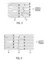
- FIG. 3is a view like FIG. 2 and shows another embodiment.
- FIG. 4is a view like FIG. 2 and shows another embodiment.
- FIGS. 1 and 2show a combination catalytic converter and filter 10 for an internal combustion engine such as diesel engine 12 .
- the combination catalytic converter and filteris provided by a single unitary flow member having an upstream frontside 14 and a downstream backside 16 .
- Member 10has a plurality of flow channels 18 extending axially from upstream frontside 14 to downstream backside 16 .
- Each channelhas left and right sidewalls such as 20 and 22 formed by pleated filter media 24 , and top and bottom walls formed by respective upper and lower boundary layers 26 and 28 .
- Left and right sidewalls 20 and 22extend axially continuously from upstream frontside 14 to downstream backside 16 .
- the sidewallshave upstream sections 30 , 32 , etc.
- Upstream sections 30 , 32 , etc.provide a catalytic section 33 treated with a catalyst for the exhaust.
- Downstream sections 34 , 36 , etc.provide a filter section 35 and have axially spaced alternately blocking sealants 38 , 40 , etc. in alternate channels such that exhaust flow must pass through pleated filter media 24 in filter section 35 , as shown at arrows such as 37 .
- Each of left and right sidewalls 20 , 22 , etc.extends axially rectilinearly from catalytic section 33 to filter section 35 , maintaining exact axial alignment of the respective channels including the catalyzing and filtering sections thereof.
- Pleated filter media 24is a continuous sheet spanning both catalytic section 33 and filter section 35 .
- catalytic section 33is upstream of filter section 35 .
- a first set of alternating blocking sealants 38 , etc.are at the upstream ends of respective channels in filter section 35
- a second set of alternating blocking sealants 40 , etc.are at downstream ends of respective channels in filter section 35 .
- the sidewalls of the channels of catalytic section 33are perforated as shown at 42 such that exhaust flows through catalytic section 33 along a first set of alternate channels such as 43 rectilinearly aligned with a first set of alternate channels such as 44 in filter section 35 , and exhaust also flows through catalytic section 33 along a second set of alternate channels such as 46 laterally offset from first set of channels 43 and communicating therewith through the perforations 42 , such that exhaust flows through all of the channels of catalytic section 33 notwithstanding the noted alternating blocking sealants 38 , 40 in filter section 35 . Exhaust flow through all of the channels of catalytic section 33 is desirable to increase surface area for catalytic activity.
- the noted first set of alternate channels 43 in catalytic section 33are open at their downstream ends 47 , and exhaust flows rectilinearly from such first set of channels 43 in catalytic section 33 to first set of alternate channels 44 in filter section 35 .
- the downstream ends of the first set of channels 44 in filter section 35are blocked by the noted second set of alternating blocking sealants 40 .
- the noted second set of alternate channels 46 in catalytic section 33are blocked at their downstream end by the noted first set of alternating blocking sealants 38 in the upstream ends of second set of alternate channels 48 in filter section 35 .
- Perforations 42are upstream of the noted first set of alternating blocking sealants 38 , such that exhaust flows axially along the noted second set of channels 46 in catalytic section 33 and then laterally through perforations 42 as shown in dashed line at arrows such as 49 in FIG. 2 and joins the flow in the first set of channels 43 in catalytic section 33 flowing axially rectilinearly into the noted first set of channels 44 in filter section 35 .
- Sealantis applied along the upper pleat tips as shown at 39 downstream of perforations 42 , to seal the upper tips of pleated filter media 24 to upper boundary layer 26 .
- Sealantis applied along the lower pleat tips as shown at 41 downstream of perforations 42 , to seal the lower tips of pleated filter media 24 to lower boundary layer 28 .
- the catalytic sectionmay be downstream of the filter section, as shown in FIG. 3 at upstream filter section 52 and downstream catalytic section 54 .
- a second catalytic sectionmay be added to the configuration of FIG. 2 downstream of the filter section, such that a filter section is nested between two catalytic sections, i.e. catalyst/filter/catalyst, for example as shown in FIG. 4 at upstream catalytic section 56 , downstream filter section 58 and further downstream catalytic section 60 .
- the filter section of the unitary memberis treated with a catalyst. For example, in FIG.
- filter section 35is further treated with a catalyst to oxidize soot or collected contaminant, while the catalytic treatment in catalytic section 33 reduces or acts upon another gaseous portion of the exhaust.
- the deviceis provided with different catalytic treatments at different sections so that separate functions occur.
- filter sections 52 , FIG. 3 and 58, FIG. 4may also be provided with catalytic treatment. Other combinations and sequencing are possible.
- the device of FIG. 1is wrapped in a spiral, for example as shown in U.S. Pat. Nos. 4,652,286 and 5,908,480, incorporated herein by reference, to provide a multilayered structure.
- one of the upper or lower boundary layers 26 or 28may be eliminated, because in a spiral wrap the remaining layer provides the boundary for the channels on opposite sides thereof.
- Boundary layers 26 and/or 28may be formed of a sheet of filter media or may be impervious to the exhaust flow. Boundary layers 26 and/or 28 may be perforated as shown at 50 and 51 which perforations are laterally aligned with perforations 42 .
- the single row of channels in FIG. 1may be stacked, for example as shown in incorporated U.S.
Landscapes
- Engineering & Computer Science (AREA)
- Chemical & Material Sciences (AREA)
- Chemical Kinetics & Catalysis (AREA)
- Combustion & Propulsion (AREA)
- Mechanical Engineering (AREA)
- General Engineering & Computer Science (AREA)
- Exhaust Gas After Treatment (AREA)
- Processes For Solid Components From Exhaust (AREA)
- Filtering Of Dispersed Particles In Gases (AREA)
- Exhaust Gas Treatment By Means Of Catalyst (AREA)
- Catalysts (AREA)
Abstract
Description
The invention relates to exhaust emission devices for internal combustion engines, including diesel engines, and more particularly to catalytic converters and to filters.
Various diesel exhaust aftertreatment systems require that the exhaust be directed through a catalytic component and also through a filter component to achieve emissions and/or particulate (e.g. soot) reduction. The present invention provides a simple system combining these devices in a singular unit. In a desirable aspect, the invention further maintains exact axial alignment of catalytic and filter flow channels and simplifies packaging.
FIG. 1 is an exploded perspective view of a combination catalytic converter and filter in accordance with the invention.
FIG. 2 is a sectional view from above of the device of FIG.1.
FIG. 3 is a view like FIG.2 and shows another embodiment.
FIG. 4 is a view like FIG.2 and shows another embodiment.
FIGS. 1 and 2 show a combination catalytic converter andfilter 10 for an internal combustion engine such asdiesel engine 12. The combination catalytic converter and filter is provided by a single unitary flow member having anupstream frontside 14 and adownstream backside 16.Member 10 has a plurality offlow channels 18 extending axially fromupstream frontside 14 todownstream backside 16. Each channel has left and right sidewalls such as20 and22 formed bypleated filter media 24, and top and bottom walls formed by respective upper andlower boundary layers right sidewalls upstream frontside 14 todownstream backside 16. The sidewalls haveupstream sections proximate frontside 14, anddownstream sections proximate backside 16.Upstream sections catalytic section 33 treated with a catalyst for the exhaust.Downstream sections filter section 35 and have axially spaced alternately blockingsealants pleated filter media 24 infilter section 35, as shown at arrows such as37. Each of left andright sidewalls catalytic section 33 tofilter section 35, maintaining exact axial alignment of the respective channels including the catalyzing and filtering sections thereof. Pleatedfilter media 24 is a continuous sheet spanning bothcatalytic section 33 andfilter section 35.
In one preferred embodiment,catalytic section 33 is upstream offilter section 35. A first set ofalternating blocking sealants 38, etc. are at the upstream ends of respective channels infilter section 35, and a second set ofalternating blocking sealants 40, etc. are at downstream ends of respective channels infilter section 35. In this embodiment, it is preferred that the sidewalls of the channels ofcatalytic section 33 are perforated as shown at42 such that exhaust flows throughcatalytic section 33 along a first set of alternate channels such as43 rectilinearly aligned with a first set of alternate channels such as44 infilter section 35, and exhaust also flows throughcatalytic section 33 along a second set of alternate channels such as46 laterally offset from first set ofchannels 43 and communicating therewith through theperforations 42, such that exhaust flows through all of the channels ofcatalytic section 33 notwithstanding the notedalternating blocking sealants filter section 35. Exhaust flow through all of the channels ofcatalytic section 33 is desirable to increase surface area for catalytic activity. In this embodiment, the noted first set ofalternate channels 43 incatalytic section 33 are open at theirdownstream ends 47, and exhaust flows rectilinearly from such first set ofchannels 43 incatalytic section 33 to first set ofalternate channels 44 infilter section 35. The downstream ends of the first set ofchannels 44 infilter section 35 are blocked by the noted second set of alternatingblocking sealants 40. The noted second set ofalternate channels 46 incatalytic section 33 are blocked at their downstream end by the noted first set of alternatingblocking sealants 38 in the upstream ends of second set ofalternate channels 48 infilter section 35.Perforations 42 are upstream of the noted first set ofalternating blocking sealants 38, such that exhaust flows axially along the noted second set ofchannels 46 incatalytic section 33 and then laterally throughperforations 42 as shown in dashed line at arrows such as49 in FIG.2 and joins the flow in the first set ofchannels 43 incatalytic section 33 flowing axially rectilinearly into the noted first set ofchannels 44 infilter section 35. Sealant is applied along the upper pleat tips as shown at39 downstream ofperforations 42, to seal the upper tips ofpleated filter media 24 toupper boundary layer 26. Sealant is applied along the lower pleat tips as shown at41 downstream ofperforations 42, to seal the lower tips of pleatedfilter media 24 tolower boundary layer 28.
In another embodiment, the catalytic section may be downstream of the filter section, as shown in FIG. 3 atupstream filter section 52 and downstreamcatalytic section 54. In a further embodiment, a second catalytic section may be added to the configuration of FIG. 2 downstream of the filter section, such that a filter section is nested between two catalytic sections, i.e. catalyst/filter/catalyst, for example as shown in FIG. 4 at upstreamcatalytic section 56,downstream filter section 58 and further downstreamcatalytic section 60. In another embodiment, the filter section of the unitary member is treated with a catalyst. For example, in FIG. 2,filter section 35 is further treated with a catalyst to oxidize soot or collected contaminant, while the catalytic treatment incatalytic section 33 reduces or acts upon another gaseous portion of the exhaust. Thus, the device is provided with different catalytic treatments at different sections so that separate functions occur. In further embodiments,filter sections 52, FIG. 3 and 58, FIG. 4, may also be provided with catalytic treatment. Other combinations and sequencing are possible.
In preferred form, the device of FIG. 1 is wrapped in a spiral, for example as shown in U.S. Pat. Nos. 4,652,286 and 5,908,480, incorporated herein by reference, to provide a multilayered structure. In such embodiment, one of the upper orlower boundary layers Boundary layers 26 and/or28 may be formed of a sheet of filter media or may be impervious to the exhaust flow.Boundary layers 26 and/or28 may be perforated as shown at50 and51 which perforations are laterally aligned withperforations 42. In another embodiment, the single row of channels in FIG. 1 may be stacked, for example as shown in incorporated U.S. Pat. No. 4,652,286, to provide a plurality of rows and columns of channels. In such stacked structure one of theboundary layers top layer 26 is omitted, thenlayer 28 of the second row of channels will provide the bottom wall for such second row of channels and will provide the top wall for the first row of channels therebelow.
It is recognized that various equivalents, alternatives and modifications are possible within the scope of the appended claims.
Claims (19)
1. A combination catalytic converter and filter for internal combustion engine exhaust comprising in a single unitary member pleated filter media and upper and lower boundary layers defining a plurality of axially extending flow channels having first and second serially sequential axial sections, one of said first and second sections being a catalytic section treated with a catalyst for said exhaust, the other of said first and second sections being a filter section with alternately sealed said channels forcing exhaust to flow through said pleated filter media, wherein said channels extend axially from upstream to downstream, said first section having a first upstream end and a first downstream end, said second section having a second upstream end and a second downstream end, said second upstream end being axially contiguous to and forming an axial junction with said first downstream end, wherein exhaust flows axially from said first upstream end then to said axial junction then axially to said second downstream end, and wherein said filter section is formed between axially spaced first and second sets of alternating blocking sealants in said channels, said first set of sealants being at said axial junction, said second set of sealants being at one of said second downstream end and said first upstream end, said first set of sealants being axially spaced between said first upstream end and said second downstream end.
2. The invention according toclaim 1 wherein said first set of sealants is axially spaced downstream from said first upstream end by said first section therebetween, and said first set of sealants is axially spaced upstream from said second downstream end by said second section therebetween.
3. The invention according toclaim 2 wherein said catalytic section is upstream of said filter section.
4. The invention according toclaim 2 wherein said filter section is upstream of said catalytic section.
5. The invention according toclaim 2 further comprising in combination a third serially sequential axial section, said second section being nested between said first and third sections in axial alignment therewith.
6. The invention according toclaim 5 wherein said first and third sections are catalytic sections, and said second section is a filter section.
7. The invention according toclaim 2 wherein said first section is said catalytic section, said second section is said filter section, said first section is upstream of said second section, said first set of alternating blocking sealants is at the upstream end of said filter section, said second set of alternating blocking sealants is at the downstream end of said filter section.
8. The invention according toclaim 2 wherein said filter section is treated with catalyst.
9. The invention according toclaim 2 wherein said upper and lower boundary layers are formed by a single layer in a spiral wrap.
10. A combination catalytic converter and filter for internal combustion engine exhaust comprising a single unitary flow member having an upstream side and a downstream side, said member having a plurality of flow channels extending axially from said upstream side to said downstream side, each channel having left and right sidewalls formed by pleated filter media, and top and bottom walls formed by respective upper and lower boundary layers, said left and right sidewalls extending axially continuously from said upstream side to said downstream side, said sidewalls having first upstream sections proximate said upstream side, said sidewalls having second downstream sections proximate said downstream side, one of said first and second sections being a catalytic section treated with a catalyst for said exhaust, the other of said first and second sections being a filter section and having axially spaced alternately blocking sealants in alternate said channels such that exhaust must flow through said pleated filter media, wherein said channels extend axially from upstream to downstream, said first section having a first upstream end and a first downstream end, said second section having a second upstream end and a second downstream end, said second upstream end being axially contiguous to and forming an axial junction with said first downstream end, wherein exhaust gas flows axially from said first upstream end then to said axial junction then axially to said second downstream end, and wherein said filter section is formed between axially spaced first and second sets of said alternating blocking sealants in said channels, said first set of sealants being at said axial junction, said second set of sealants being at one of said second downstream end and said first upstream end, said first set of sealants being axially spaced between said first upstream end and said second downstream end.
11. The invention according toclaim 10 wherein said first set of sealants is axially spaced downstream from said first upstream end by said first section therebetween, and said first set of sealants is axially spaced upstream from said second downstream end by said second section therebetween.
12. The invention according theclaim 11 wherein said sidewalls of said catalytic section are perforated such that exhaust flows through said catalytic section along a first set of alternate channels axially rectilinearly aligned with a first set of alternate channels in said filter section, and exhaust flows through said catalytic section along a second set of alternate channels laterally offset from said first set of channels and communicating therewith through said perforations, such that exhaust flows through all of the channels of said catalytic section, increasing surface area for catalytic activity, notwithstanding said alternating blocking sealants in said filter section.
13. The invention according toclaim 11 wherein said sidewalls have third downstream sections downstream of said second sections, said second sections being nested between in axial alignment with said first and third sections, each of said left and right sidewalls of each channel extending axially rectilinearly from said first section to said second section to said third section, maintaining exact axial alignment of the respective said channel.
14. The invention according toclaim 13 wherein said first and third sections are catalytic sections, and said second section is a filter section.
15. The invention according toclaim 11 wherein said filter section is treated with catalyst.
16. The invention according toclaim 11 wherein said upper and lower boundary layers are formed by a single layer in a spiral wrap.
17. A combination catalytic converter and filter for internal combustion engine exhaust comprising a single unitary flow member having an upstream side and a downstream side, said member having a plurality of flow channels extending axially from said upstream side to said downstream side, each channel having left and right sidewalls formed by pleated filter media, and top and bottom walls formed by respective upper and lower boundary layers, said left and right sidewalls extending axially continuously from said upstream side to said downstream side, said sidewalls having first upstream sections proximate said upstream side, said sidewalls having second downstream sections proximate said downstream side, one of said first and second sections being a catalytic section treated with a catalyst for said exhaust, the other of said first and second sections being a filter section and having axially spaced alternately blocking sealants in alternate said channels such that exhaust must flow through said pleated filter media, wherein said sidewalls of said catalytic section are perforated such that exhaust flows through said catalytic section along a first set of alternate channels axially rectilinearly aligned with a first set of alternate channels in said filter section, and exhaust flows through said catalytic section along a second set of alternate channels laterally offset from said first set of channels and communicating therewith through said perforations, such that exhaust flows through all of the channels of said catalytic section, increasing surface area for catalytic activity, notwithstanding said alternating blocking sealants in said filter section, and wherein:
said catalytic section is axially upstream of said filter section;
said axially spaced alternating blocking sealants comprise a first set of alternating blocking sealants at the upstream end of said filter section and a second set of alternating blocking sealants at the downstream end of said filter section;
said first set of alternate channels in said catalytic section are open at their downstream ends, and exhaust flows rectilinearly from said first set of channels in said catalytic section to said first set of channels in said filter section, the downstream ends of said first set of channels in said filter section being blocked by said second set of said alternating blocking sealants;
said second set of alternate channels in said catalytic section are blocked at their downstream end by said first set of said alternating blocking sealants in the upstream ends of a second set of alternate channels in said filter section;
said perforations are upstream of said first set of alternating blocking sealants, such that exhaust flows axially along said second set of channels in said catalytic section and then laterally through said perforations and joins said flow in said first set of channels in said catalytic section flowing axially rectilinearly into said first set of channels in said filter section.
18. A combination catalytic converter and filter for internal combustion engine exhaust comprising a single unitary flow member having an upstream side and a downstream side, said member having a plurality of flow channels extending axially from said upstream side to said downstream side, each channel having left and right sidewalls formed by pleated filter media, and top and bottom walls formed by respective upper and lower boundary layers, said left and right sidewalls extending axially continuously from said upstream side to said downstream side, said sidewalls having first upstream sections proximate said upstream side, said sidewalls having second downstream sections proximate said downstream side, one of said first and second sections being a catalytic section treated with a catalyst for said exhaust, the other of said first and second sections being a filter section and having axially spaced alternately blocking sealants in alternate said channels such that exhaust must flow through said pleated filter media, wherein said sidewalls of said catalytic section are perforated such that exhaust flows through said catalytic section along a first set of alternate channels axially rectilinearly aligned with a first set of alternate channels in said filter section, and exhaust flows through said catalytic section along a second set of alternate channels laterally offset from said first set of channels and communicating therewith through said perforations, such that exhaust flows through all of the channels of said catalytic section, increasing surface area for catalytic activity, notwithstanding said alternating blocking sealants in said filter section, and wherein:
said filter section is axially upstream of said catalytic section;
said axially spaced alternating blocking sealants comprise a first set of alternating blocking sealants at the upstream end of said filter section and a second set of alternating blocking sealants at the downstream end of said filter section;
said first set of alternate channels in said catalytic section are open at their upstream ends, and exhaust flows rectilinearly from said first set of channels in said filter section to said first set of channels in said catalytic section, the upstream ends of said first set of channels in said filter section being blocked by said first set of said alternating blocking sealants;
said second set of alternate channels in said catalytic section are blocked at their upstream end by said second set of alternating blocking sealants in the downstream ends of said second set of alternate channels in said filter section;
said perforations are downstream of said second set of alternating blocking sealants, such that exhaust flows axially along said first set of channels in said filter section and then some of the exhaust flows laterally through said perforations and then flows axially rectilinearly along said second set of channels in said catalytic section.
19. A combination catalytic converter and filter for internal combustion engine exhaust comprising a single unitary flow member having an upstream side and a downstream side, said member having a plurality of flow channels extending axially from said upstream side to said downstream side, each channel having left and right sidewalls formed by pleated filter media, and top and bottom walls formed by respective upper and lower boundary layers, said left and right sidewalls extending axially continuously from said upstream side to said downstream side, said sidewalls having first upstream sections proximate said upstream side, said sidewalls having second downstream sections proximate said downstream side, one of said first and second sections being a catalytic section treated with a catalyst for said exhaust, the other of said first and second sections being a filter section and having axially spaced alternately blocking sealants in alternate said channels such that exhaust must flow through said pleated filter media, wherein each of said left and right sidewalls of each channel extends axially rectilinearly from said first section to said second section, maintaining exact axial alignment of the respective said channel including the catalyzing and filtering sections thereof, wherein said sidewalls have third downstream sections downstream of said second sections, said second sections being nested between in axial alignment with said first and third sections, each of said left and right sidewalls of each channel extending axially rectilinearly from said first section to said second section to said third section, maintaining exact axial alignment of the respective said channel, wherein said first and third sections are catalytic sections, and said second section is a filter section, and wherein said sidewalls of said first and third catalytic sections are perforated such that exhaust flows through said first catalytic section along a first set of alternate channels axially rectilinearly aligned with a first set of alternate channels in said second filter section, and exhaust flows through said first catalytic section along a second set of alternate channels laterally offset from said first set of channels and communicating therewith through said perforations, such that exhaust flows through all of the channels of said first catalytic section, increasing surface area for catalytic activity, notwithstanding said alternating blocking sealants in said second filter section, and exhaust flows from a second set of alternate channels in said second filter section rectilinearly aligned with a first set of alternate channels in said third catalytic section, and exhaust also flows from said second set of channels in said second filter section through said perforations in said sidewalls of said third catalytic section and then axially along a second set of alternate channels in said third catalytic section, such that exhaust flows through all of the channels in said third catalytic section, increasing surface area for catalytic activity, notwithstanding said alternating blocking sealants in said second filter section.
Priority Applications (9)
| Application Number | Priority Date | Filing Date | Title |
|---|---|---|---|
| US09/522,152US6669913B1 (en) | 2000-03-09 | 2000-03-09 | Combination catalytic converter and filter |
| AU16756/01AAU1675601A (en) | 2000-03-09 | 2001-01-31 | Combination catalytic converter and filter |
| BR0100792-0ABR0100792A (en) | 2000-03-09 | 2001-02-23 | Combination of catalytic converter and filter for combustion engine discharge |
| EP01104985AEP1132587A3 (en) | 2000-03-09 | 2001-03-01 | Combination catalytic converter and filter |
| JP2001060121AJP2001295625A (en) | 2000-03-09 | 2001-03-05 | Combination of catalytic converter and filter |
| US09/851,300US6776814B2 (en) | 2000-03-09 | 2001-05-08 | Dual section exhaust aftertreatment filter and method |
| US10/075,035US7211226B2 (en) | 2000-03-09 | 2002-02-12 | Catalyst and filter combination |
| US10/325,001US7052532B1 (en) | 2000-03-09 | 2002-12-20 | High temperature nanofilter, system and method |
| US11/333,737US7235124B2 (en) | 2000-03-09 | 2006-01-17 | High temperature nanofilter, system and method |
Applications Claiming Priority (1)
| Application Number | Priority Date | Filing Date | Title |
|---|---|---|---|
| US09/522,152US6669913B1 (en) | 2000-03-09 | 2000-03-09 | Combination catalytic converter and filter |
Related Parent Applications (1)
| Application Number | Title | Priority Date | Filing Date |
|---|---|---|---|
| US09/851,300Continuation-In-PartUS6776814B2 (en) | 2000-03-09 | 2001-05-08 | Dual section exhaust aftertreatment filter and method |
Related Child Applications (3)
| Application Number | Title | Priority Date | Filing Date |
|---|---|---|---|
| US09/851,300Continuation-In-PartUS6776814B2 (en) | 2000-03-09 | 2001-05-08 | Dual section exhaust aftertreatment filter and method |
| PCT/US2002/002133Continuation-In-PartWO2002079764A1 (en) | 2000-03-09 | 2002-01-25 | Surface-enhanced spectroscopy-active sandwich nanoparticles |
| US10/075,035Continuation-In-PartUS7211226B2 (en) | 2000-03-09 | 2002-02-12 | Catalyst and filter combination |
Publications (1)
| Publication Number | Publication Date |
|---|---|
| US6669913B1true US6669913B1 (en) | 2003-12-30 |
Family
ID=24079673
Family Applications (1)
| Application Number | Title | Priority Date | Filing Date |
|---|---|---|---|
| US09/522,152Expired - LifetimeUS6669913B1 (en) | 2000-03-09 | 2000-03-09 | Combination catalytic converter and filter |
Country Status (5)
| Country | Link |
|---|---|
| US (1) | US6669913B1 (en) |
| EP (1) | EP1132587A3 (en) |
| JP (1) | JP2001295625A (en) |
| AU (1) | AU1675601A (en) |
| BR (1) | BR0100792A (en) |
Cited By (33)
| Publication number | Priority date | Publication date | Assignee | Title |
|---|---|---|---|---|
| US20020053202A1 (en)* | 2000-09-08 | 2002-05-09 | Nissan Motor Co., Ltd | Exhaust gas purifying system and method |
| US20030097834A1 (en)* | 2001-11-16 | 2003-05-29 | Isuzu Motors Limited | Exhaust gas purification system |
| US20030190269A1 (en)* | 2000-03-09 | 2003-10-09 | Liu Z. Gerald | Catalyst and filter combination |
| US20050031513A1 (en)* | 2001-08-01 | 2005-02-10 | Mcnamara John Martin | Gasoline engine with an exhaust system for combusting particulate matter |
| US6946013B2 (en) | 2002-10-28 | 2005-09-20 | Geo2 Technologies, Inc. | Ceramic exhaust filter |
| US20050217258A1 (en)* | 2002-08-02 | 2005-10-06 | Emitec Gesellschaft Fur Emissionstechnologie Mbh | Exhaust gas filter and method for cleaning an exhaust gas |
| US7052532B1 (en)* | 2000-03-09 | 2006-05-30 | 3M Innovative Properties Company | High temperature nanofilter, system and method |
| US20060236680A1 (en)* | 2005-04-26 | 2006-10-26 | Wenzhong Zhang | Method for regenerating a diesel particulate filter |
| US20060236684A1 (en)* | 2005-04-26 | 2006-10-26 | Wenzhong Zhang | Diesel particulate matter reduction system |
| US7211232B1 (en) | 2005-11-07 | 2007-05-01 | Geo2 Technologies, Inc. | Refractory exhaust filtering method and apparatus |
| US20070134138A1 (en)* | 2005-12-14 | 2007-06-14 | Honda Motor Co., Ltd. | Exhaust gas purifying apparatus |
| US20080120952A1 (en)* | 2006-11-28 | 2008-05-29 | Chilton Donald T | Cross-Flow Filter Media and Filter Assembly |
| US7444805B2 (en) | 2005-12-30 | 2008-11-04 | Geo2 Technologies, Inc. | Substantially fibrous refractory device for cleaning a fluid |
| US7451849B1 (en) | 2005-11-07 | 2008-11-18 | Geo2 Technologies, Inc. | Substantially fibrous exhaust screening system for motor vehicles |
| US20090041074A1 (en)* | 2007-08-08 | 2009-02-12 | Emcore Corporation | Passivation of Vertical Cavity Surface Emitting Lasers |
| US20090038294A1 (en)* | 2007-08-09 | 2009-02-12 | Anderson Matthew L | Tuning Particulate Filter Performance Through Selective Plugging and Use of Multiple Particulate Filters to Reduce Emissions and Improve Thermal Robustness |
| US20090056319A1 (en)* | 2007-09-04 | 2009-03-05 | Warner Jay V | Exhaust Aftertreatment System with Pre-Catalysis |
| US20090084094A1 (en)* | 2007-10-02 | 2009-04-02 | Goss James R | Exhaust Aftertreatment System with Compliantly Coupled Sections |
| US20090139400A1 (en)* | 2005-12-05 | 2009-06-04 | Eidgenossische Materialprufungs- Und Forschung- Sanstalt Empa | Diffuser For Exhaust Gas Cleaning Systems |
| US7563415B2 (en) | 2006-03-03 | 2009-07-21 | Geo2 Technologies, Inc | Catalytic exhaust filter device |
| US7572311B2 (en) | 2002-10-28 | 2009-08-11 | Geo2 Technologies, Inc. | Highly porous mullite particulate filter substrate |
| US7574796B2 (en) | 2002-10-28 | 2009-08-18 | Geo2 Technologies, Inc. | Nonwoven composites and related products and methods |
| US7582270B2 (en) | 2002-10-28 | 2009-09-01 | Geo2 Technologies, Inc. | Multi-functional substantially fibrous mullite filtration substrates and devices |
| US7682577B2 (en) | 2005-11-07 | 2010-03-23 | Geo2 Technologies, Inc. | Catalytic exhaust device for simplified installation or replacement |
| US7682578B2 (en) | 2005-11-07 | 2010-03-23 | Geo2 Technologies, Inc. | Device for catalytically reducing exhaust |
| US7722828B2 (en) | 2005-12-30 | 2010-05-25 | Geo2 Technologies, Inc. | Catalytic fibrous exhaust system and method for catalyzing an exhaust gas |
| US20100154370A1 (en)* | 2008-12-22 | 2010-06-24 | Caterpillar Inc, | System and methods for particulate filter |
| US20100307138A1 (en)* | 2009-06-04 | 2010-12-09 | Wen-Lo Chen | Diesel engine exhaust purifier |
| US7862640B2 (en) | 2006-03-21 | 2011-01-04 | Donaldson Company, Inc. | Low temperature diesel particulate matter reduction system |
| US20110005394A1 (en)* | 2007-07-13 | 2011-01-13 | Joriman Jon D | Media for removal of organic compounds |
| US7967887B1 (en) | 2006-11-03 | 2011-06-28 | Cummins Filtration Ip, Inc. | Exhaust aftertreatment filter with reduced maximum temperature |
| CN106823617A (en)* | 2017-03-31 | 2017-06-13 | 盛春莉 | A kind of filter medium bag, air cleaner and filter medium packet preparation method |
| US11975287B2 (en) | 2018-10-16 | 2024-05-07 | Parker-Hannifin Corporation | Pleated channel flow filter and/or roll form method |
Families Citing this family (8)
| Publication number | Priority date | Publication date | Assignee | Title |
|---|---|---|---|---|
| US6776814B2 (en) | 2000-03-09 | 2004-08-17 | Fleetguard, Inc. | Dual section exhaust aftertreatment filter and method |
| JP3872384B2 (en) | 2002-06-13 | 2007-01-24 | トヨタ自動車株式会社 | Exhaust gas purification filter catalyst |
| US7090714B2 (en) | 2002-06-17 | 2006-08-15 | Hitachi Metals, Ltd. | Ceramic honeycomb filter |
| JP4222599B2 (en) | 2002-10-10 | 2009-02-12 | 日本碍子株式会社 | Honeycomb structure, manufacturing method thereof, and exhaust gas purification system using the honeycomb structure |
| JP2004162626A (en) | 2002-11-14 | 2004-06-10 | Hitachi Ltd | Exhaust gas purification device |
| DE202007002430U1 (en)* | 2007-02-15 | 2008-06-26 | Mann + Hummel Gmbh | Diesel particulate filter with a ceramic filter body |
| WO2008113507A1 (en)* | 2007-03-16 | 2008-09-25 | Elringklinger Ag | Diesel particulate filter component |
| TWI549736B (en)* | 2015-06-17 | 2016-09-21 | Pa E Machinery Ind Co Ltd | Multi-core filter with water collection |
Citations (61)
| Publication number | Priority date | Publication date | Assignee | Title |
|---|---|---|---|---|
| US1893372A (en) | 1929-01-11 | 1933-01-03 | Mine Safety Appliances Co | Apparatus for treating exhaust gases of internal combustion engines |
| US1924472A (en) | 1930-11-28 | 1933-08-29 | Thomson George Miller | Method of and means for manufacturing sound absorbing material |
| GB563768A (en) | 1943-02-08 | 1944-08-29 | Cecil Gordon Vokes | Improvements relating to filters |
| US2410371A (en) | 1943-02-08 | 1946-10-29 | Vokes Cecil Gordon | Filter |
| US2553054A (en) | 1948-01-02 | 1951-05-15 | Lincoln | Machine and method for producing a continuous honeycomb structure |
| US3025964A (en) | 1958-09-29 | 1962-03-20 | Mine Safety Appliances Co | Zigzag filter element and method of making it |
| US3441381A (en) | 1965-06-22 | 1969-04-29 | Engelhard Ind Inc | Apparatus for purifying exhaust gases of an internal combustion engine |
| US3692184A (en) | 1970-10-07 | 1972-09-19 | Carborundum Co | Filter cartridge and pack therefor and method of making same |
| US3708957A (en) | 1971-02-19 | 1973-01-09 | Farr Co | Exhaust filter unit and method of filtering exhaust |
| US3799354A (en) | 1972-03-11 | 1974-03-26 | Gen Motors Corp | Fluid filter elements |
| US3844749A (en) | 1972-06-01 | 1974-10-29 | Thermo Kinetics Inc | High velocity filter |
| US4056375A (en) | 1975-09-17 | 1977-11-01 | Firma Carl Freudenberg | Gas filter element |
| US4130487A (en) | 1976-04-05 | 1978-12-19 | Process Scientific Innovations Ltd. | Filters for liquids or gases |
| US4157902A (en) | 1975-09-22 | 1979-06-12 | Donaldson Company, Inc. | Air cleaner system for over-highway trucks |
| US4410427A (en) | 1981-11-02 | 1983-10-18 | Donaldson Company, Inc. | Fluid filtering device |
| US4419108A (en) | 1982-02-22 | 1983-12-06 | Corning Glass Works | Filter apparatus and method of filtering |
| US4430223A (en) | 1981-02-25 | 1984-02-07 | Nippondenso Co., Ltd. | Filter element for filtering fluid and method of producing same |
| US4441899A (en) | 1980-12-30 | 1984-04-10 | Nippon Soken, Inc. | Dust collecting filter |
| US4455823A (en) | 1982-10-20 | 1984-06-26 | General Motors Corporation | Diesel exhaust particulate trap with pleated filter |
| US4498989A (en) | 1981-02-23 | 1985-02-12 | Nippondenso Co., Ltd. | Fluid filter element and support |
| US4542286A (en) | 1982-12-03 | 1985-09-17 | Simplex Time Recorder Co. | Time card and carrier |
| US4548626A (en) | 1984-04-30 | 1985-10-22 | Figgie International Inc. | Particulate air filter assembly |
| US4619675A (en) | 1983-06-24 | 1986-10-28 | Midori Anzen Co., Ltd. | Filter for air cleaners |
| US4652286A (en) | 1982-02-16 | 1987-03-24 | Matsushita Electric Industrial Co., Ltd. | Exhaust gas filter |
| WO1988003431A1 (en) | 1986-11-04 | 1988-05-19 | Eastman Kodak Company | Liquid filter apparatus |
| US4857089A (en)* | 1987-01-28 | 1989-08-15 | Ngk Insulators, Ltd. | Ceramic honeycomb filter for purifying exhaust gases |
| US4878929A (en) | 1989-02-01 | 1989-11-07 | Nelson Industries Inc. | Liquid-gas separator |
| US4902487A (en) | 1988-05-13 | 1990-02-20 | Johnson Matthey, Inc. | Treatment of diesel exhaust gases |
| US4925561A (en) | 1988-03-31 | 1990-05-15 | Tsuchiya Mfg. Co., Ltd. | Composite planar and triangularly pleated filter element |
| US5008086A (en) | 1988-10-28 | 1991-04-16 | Minnesota Mining And Manufacturing Company | Erosion resistant mounting composite for catalytic converter |
| US5015376A (en) | 1990-01-22 | 1991-05-14 | Picek Charles R | Semi-rigid enhanced area filter element |
| US5030263A (en) | 1988-10-20 | 1991-07-09 | Ac Rochester Overseas Corporation | Motor vehicle filter element |
| US5035236A (en) | 1989-07-18 | 1991-07-30 | Smiths Industries Public Limited Company | Filtration device for respiratory gasses with heat and moisture exchange |
| US5089237A (en)* | 1989-07-20 | 1992-02-18 | Daimler-Benz Ag | Gas filter with catalytic coating and a gastight downstream region |
| US5106397A (en) | 1990-12-26 | 1992-04-21 | Ford Motor Company | Air cleaner/noise silencer assembly |
| US5137696A (en) | 1989-02-21 | 1992-08-11 | Usui Kokusai Sangyo Kabushiki Kaisha | Exhaust gas cleaning device |
| US5174895A (en) | 1988-03-16 | 1992-12-29 | Mordeki Drori | Coiled filter strip with upstream and downstream butt ends |
| US5252299A (en) | 1992-05-28 | 1993-10-12 | Retallick William B | Catalytic air cleaner |
| USD342990S (en) | 1991-12-13 | 1994-01-04 | Ford Motor Company | Air filter element |
| US5298046A (en) | 1993-01-06 | 1994-03-29 | Minnesota Mining And Manufacturing Company | Diesel particulate filter element and filter |
| US5304351A (en) | 1990-11-13 | 1994-04-19 | Nippon Steel Corporation | Semi-oval shaped carrier having excellent thermal stress resistance and thermal fatigue resistance for automobile exhaust gas-purifying catalyst |
| US5322537A (en) | 1992-04-28 | 1994-06-21 | Matsushita Electric Industrial Co., Ltd. | Exhaust gas filter and method for making the same |
| US5346675A (en) | 1988-12-16 | 1994-09-13 | Usui Kokusai Sangyo Kabushiki Kaisha | Exhaust gas cleaning apparatus |
| US5380501A (en) | 1989-05-08 | 1995-01-10 | Usui Kokusai Sangyo Kabushiki Kaisha | Exhaust gas cleaning device |
| US5385873A (en) | 1991-03-22 | 1995-01-31 | Acs Industries, Inc. | High temperature resistant material |
| US5468384A (en) | 1992-10-20 | 1995-11-21 | Societe Anonyme Dite Societe Des Ceramiques Techniques | Module for filtering, separating, purifying gases or liquids, or for catalytic conversion |
| US5480621A (en) | 1988-04-25 | 1996-01-02 | Emitec Gesellschaft Fuer Emissionstechnologie Mbh | Electrically conductive honeycomb as an exhaust gas catalyst carrier body |
| US5546069A (en) | 1994-11-17 | 1996-08-13 | Motorola, Inc. | Taut armature resonant impulse transducer |
| US5549722A (en) | 1994-12-30 | 1996-08-27 | Dana Corporation | Air filter assemblies and a frustoconical air filter element for use with the assemblies |
| US5562825A (en) | 1993-05-21 | 1996-10-08 | Nippondenso Co., Ltd. | Filter element having a flat and non-flat configuration |
| US5632792A (en) | 1995-08-16 | 1997-05-27 | Purolator Products Company | Air induction filter hose assembly |
| US5772883A (en) | 1996-04-26 | 1998-06-30 | Donaldson Company, Inc. | Slanted inline filter |
| US5792247A (en) | 1996-04-26 | 1998-08-11 | Donaldson Company, Inc. | Integrated resonator and filter apparatus |
| US5820646A (en) | 1996-04-26 | 1998-10-13 | Donaldson Company, Inc. | Inline filter apparatus |
| US5846641A (en) | 1997-03-20 | 1998-12-08 | Exxon Research And Engineering Company | Multi-layer membrane composites and their use in hydrocarbon partical oxidation |
| US5863311A (en) | 1995-05-30 | 1999-01-26 | Sumitomo Electric Industries, Ltd. | Particulate trap for diesel engine |
| US5891402A (en) | 1994-03-02 | 1999-04-06 | W. L. Gore & Associates, Inc. | Catalyst retaining apparatus and use in an ozone filter |
| US5902364A (en) | 1996-04-26 | 1999-05-11 | Donaldson Company, Inc. | Conical filter |
| US5908480A (en) | 1996-03-29 | 1999-06-01 | Sumitomo Electric Industries, Ltd. | Particulate trap for diesel engine |
| US5925561A (en) | 1996-06-07 | 1999-07-20 | New Holland North America, Inc. | Control system for a rotary composter |
| US5961931A (en) | 1994-10-13 | 1999-10-05 | Sumitomo Electric Industries, Ltd. | Particulate trap |
Family Cites Families (4)
| Publication number | Priority date | Publication date | Assignee | Title |
|---|---|---|---|---|
| DE4024942A1 (en)* | 1990-08-06 | 1992-02-13 | Emitec Emissionstechnologie | MONOLITHIC METAL HONEYCOMB WITH VARIOUS CHANNEL NUMBER |
| US5396764A (en)* | 1994-02-14 | 1995-03-14 | Ford Motor Company | Spark ignition engine exhaust system |
| US6013599A (en)* | 1998-07-15 | 2000-01-11 | Redem Corporation | Self-regenerating diesel exhaust particulate filter and material |
| JP2002030924A (en)* | 2000-07-17 | 2002-01-31 | Nissan Diesel Motor Co Ltd | Exhaust emission control device for diesel engine |
- 2000
- 2000-03-09USUS09/522,152patent/US6669913B1/ennot_activeExpired - Lifetime
- 2001
- 2001-01-31AUAU16756/01Apatent/AU1675601A/ennot_activeAbandoned
- 2001-02-23BRBR0100792-0Apatent/BR0100792A/ennot_activeApplication Discontinuation
- 2001-03-01EPEP01104985Apatent/EP1132587A3/ennot_activeWithdrawn
- 2001-03-05JPJP2001060121Apatent/JP2001295625A/enactivePending
Patent Citations (63)
| Publication number | Priority date | Publication date | Assignee | Title |
|---|---|---|---|---|
| US1893372A (en) | 1929-01-11 | 1933-01-03 | Mine Safety Appliances Co | Apparatus for treating exhaust gases of internal combustion engines |
| US1924472A (en) | 1930-11-28 | 1933-08-29 | Thomson George Miller | Method of and means for manufacturing sound absorbing material |
| GB563768A (en) | 1943-02-08 | 1944-08-29 | Cecil Gordon Vokes | Improvements relating to filters |
| US2410371A (en) | 1943-02-08 | 1946-10-29 | Vokes Cecil Gordon | Filter |
| US2553054A (en) | 1948-01-02 | 1951-05-15 | Lincoln | Machine and method for producing a continuous honeycomb structure |
| US3025964A (en) | 1958-09-29 | 1962-03-20 | Mine Safety Appliances Co | Zigzag filter element and method of making it |
| US3441381A (en) | 1965-06-22 | 1969-04-29 | Engelhard Ind Inc | Apparatus for purifying exhaust gases of an internal combustion engine |
| US3692184A (en) | 1970-10-07 | 1972-09-19 | Carborundum Co | Filter cartridge and pack therefor and method of making same |
| US3708957A (en) | 1971-02-19 | 1973-01-09 | Farr Co | Exhaust filter unit and method of filtering exhaust |
| US3799354A (en) | 1972-03-11 | 1974-03-26 | Gen Motors Corp | Fluid filter elements |
| US3844749A (en) | 1972-06-01 | 1974-10-29 | Thermo Kinetics Inc | High velocity filter |
| US4056375A (en) | 1975-09-17 | 1977-11-01 | Firma Carl Freudenberg | Gas filter element |
| US4056375B1 (en) | 1975-09-17 | 1987-01-20 | ||
| US4157902A (en) | 1975-09-22 | 1979-06-12 | Donaldson Company, Inc. | Air cleaner system for over-highway trucks |
| US4130487A (en) | 1976-04-05 | 1978-12-19 | Process Scientific Innovations Ltd. | Filters for liquids or gases |
| US4441899A (en) | 1980-12-30 | 1984-04-10 | Nippon Soken, Inc. | Dust collecting filter |
| US4498989A (en) | 1981-02-23 | 1985-02-12 | Nippondenso Co., Ltd. | Fluid filter element and support |
| US4430223A (en) | 1981-02-25 | 1984-02-07 | Nippondenso Co., Ltd. | Filter element for filtering fluid and method of producing same |
| US4410427A (en) | 1981-11-02 | 1983-10-18 | Donaldson Company, Inc. | Fluid filtering device |
| US4589983A (en) | 1981-11-02 | 1986-05-20 | Donaldson Company, Inc. | Fluid filtering device |
| US4652286A (en) | 1982-02-16 | 1987-03-24 | Matsushita Electric Industrial Co., Ltd. | Exhaust gas filter |
| US4419108A (en) | 1982-02-22 | 1983-12-06 | Corning Glass Works | Filter apparatus and method of filtering |
| US4455823A (en) | 1982-10-20 | 1984-06-26 | General Motors Corporation | Diesel exhaust particulate trap with pleated filter |
| US4542286A (en) | 1982-12-03 | 1985-09-17 | Simplex Time Recorder Co. | Time card and carrier |
| US4619675A (en) | 1983-06-24 | 1986-10-28 | Midori Anzen Co., Ltd. | Filter for air cleaners |
| US4548626A (en) | 1984-04-30 | 1985-10-22 | Figgie International Inc. | Particulate air filter assembly |
| WO1988003431A1 (en) | 1986-11-04 | 1988-05-19 | Eastman Kodak Company | Liquid filter apparatus |
| US4857089A (en)* | 1987-01-28 | 1989-08-15 | Ngk Insulators, Ltd. | Ceramic honeycomb filter for purifying exhaust gases |
| US5174895A (en) | 1988-03-16 | 1992-12-29 | Mordeki Drori | Coiled filter strip with upstream and downstream butt ends |
| US4925561A (en) | 1988-03-31 | 1990-05-15 | Tsuchiya Mfg. Co., Ltd. | Composite planar and triangularly pleated filter element |
| US5480621A (en) | 1988-04-25 | 1996-01-02 | Emitec Gesellschaft Fuer Emissionstechnologie Mbh | Electrically conductive honeycomb as an exhaust gas catalyst carrier body |
| US4902487A (en) | 1988-05-13 | 1990-02-20 | Johnson Matthey, Inc. | Treatment of diesel exhaust gases |
| US5030263A (en) | 1988-10-20 | 1991-07-09 | Ac Rochester Overseas Corporation | Motor vehicle filter element |
| US5008086A (en) | 1988-10-28 | 1991-04-16 | Minnesota Mining And Manufacturing Company | Erosion resistant mounting composite for catalytic converter |
| US5346675A (en) | 1988-12-16 | 1994-09-13 | Usui Kokusai Sangyo Kabushiki Kaisha | Exhaust gas cleaning apparatus |
| US4878929A (en) | 1989-02-01 | 1989-11-07 | Nelson Industries Inc. | Liquid-gas separator |
| US5137696A (en) | 1989-02-21 | 1992-08-11 | Usui Kokusai Sangyo Kabushiki Kaisha | Exhaust gas cleaning device |
| US5380501A (en) | 1989-05-08 | 1995-01-10 | Usui Kokusai Sangyo Kabushiki Kaisha | Exhaust gas cleaning device |
| US5035236A (en) | 1989-07-18 | 1991-07-30 | Smiths Industries Public Limited Company | Filtration device for respiratory gasses with heat and moisture exchange |
| US5089237A (en)* | 1989-07-20 | 1992-02-18 | Daimler-Benz Ag | Gas filter with catalytic coating and a gastight downstream region |
| US5015376A (en) | 1990-01-22 | 1991-05-14 | Picek Charles R | Semi-rigid enhanced area filter element |
| US5304351A (en) | 1990-11-13 | 1994-04-19 | Nippon Steel Corporation | Semi-oval shaped carrier having excellent thermal stress resistance and thermal fatigue resistance for automobile exhaust gas-purifying catalyst |
| US5106397A (en) | 1990-12-26 | 1992-04-21 | Ford Motor Company | Air cleaner/noise silencer assembly |
| US5385873A (en) | 1991-03-22 | 1995-01-31 | Acs Industries, Inc. | High temperature resistant material |
| USD342990S (en) | 1991-12-13 | 1994-01-04 | Ford Motor Company | Air filter element |
| US5322537A (en) | 1992-04-28 | 1994-06-21 | Matsushita Electric Industrial Co., Ltd. | Exhaust gas filter and method for making the same |
| US5252299A (en) | 1992-05-28 | 1993-10-12 | Retallick William B | Catalytic air cleaner |
| US5468384A (en) | 1992-10-20 | 1995-11-21 | Societe Anonyme Dite Societe Des Ceramiques Techniques | Module for filtering, separating, purifying gases or liquids, or for catalytic conversion |
| US5298046A (en) | 1993-01-06 | 1994-03-29 | Minnesota Mining And Manufacturing Company | Diesel particulate filter element and filter |
| US5562825A (en) | 1993-05-21 | 1996-10-08 | Nippondenso Co., Ltd. | Filter element having a flat and non-flat configuration |
| US5891402A (en) | 1994-03-02 | 1999-04-06 | W. L. Gore & Associates, Inc. | Catalyst retaining apparatus and use in an ozone filter |
| US5961931A (en) | 1994-10-13 | 1999-10-05 | Sumitomo Electric Industries, Ltd. | Particulate trap |
| US5546069A (en) | 1994-11-17 | 1996-08-13 | Motorola, Inc. | Taut armature resonant impulse transducer |
| US5549722A (en) | 1994-12-30 | 1996-08-27 | Dana Corporation | Air filter assemblies and a frustoconical air filter element for use with the assemblies |
| US5863311A (en) | 1995-05-30 | 1999-01-26 | Sumitomo Electric Industries, Ltd. | Particulate trap for diesel engine |
| US5632792A (en) | 1995-08-16 | 1997-05-27 | Purolator Products Company | Air induction filter hose assembly |
| US5908480A (en) | 1996-03-29 | 1999-06-01 | Sumitomo Electric Industries, Ltd. | Particulate trap for diesel engine |
| US5820646A (en) | 1996-04-26 | 1998-10-13 | Donaldson Company, Inc. | Inline filter apparatus |
| US5902364A (en) | 1996-04-26 | 1999-05-11 | Donaldson Company, Inc. | Conical filter |
| US5792247A (en) | 1996-04-26 | 1998-08-11 | Donaldson Company, Inc. | Integrated resonator and filter apparatus |
| US5772883A (en) | 1996-04-26 | 1998-06-30 | Donaldson Company, Inc. | Slanted inline filter |
| US5925561A (en) | 1996-06-07 | 1999-07-20 | New Holland North America, Inc. | Control system for a rotary composter |
| US5846641A (en) | 1997-03-20 | 1998-12-08 | Exxon Research And Engineering Company | Multi-layer membrane composites and their use in hydrocarbon partical oxidation |
Cited By (50)
| Publication number | Priority date | Publication date | Assignee | Title |
|---|---|---|---|---|
| US7211226B2 (en)* | 2000-03-09 | 2007-05-01 | Fleetgaurd, Inc. | Catalyst and filter combination |
| US20030190269A1 (en)* | 2000-03-09 | 2003-10-09 | Liu Z. Gerald | Catalyst and filter combination |
| US7235124B2 (en)* | 2000-03-09 | 2007-06-26 | 3M Innovative Properties Company | High temperature nanofilter, system and method |
| US7052532B1 (en)* | 2000-03-09 | 2006-05-30 | 3M Innovative Properties Company | High temperature nanofilter, system and method |
| US6916450B2 (en)* | 2000-09-08 | 2005-07-12 | Nissan Motor Co., Ltd. | Exhaust gas purifying system and method |
| US20020053202A1 (en)* | 2000-09-08 | 2002-05-09 | Nissan Motor Co., Ltd | Exhaust gas purifying system and method |
| US20050031513A1 (en)* | 2001-08-01 | 2005-02-10 | Mcnamara John Martin | Gasoline engine with an exhaust system for combusting particulate matter |
| US20110232266A1 (en)* | 2001-08-01 | 2011-09-29 | Johnson Matthey Public Limited Company | Gasoline engine with an exhaust system for combusting particulate matter |
| US20030097834A1 (en)* | 2001-11-16 | 2003-05-29 | Isuzu Motors Limited | Exhaust gas purification system |
| US20050217258A1 (en)* | 2002-08-02 | 2005-10-06 | Emitec Gesellschaft Fur Emissionstechnologie Mbh | Exhaust gas filter and method for cleaning an exhaust gas |
| US7347042B2 (en)* | 2002-08-02 | 2008-03-25 | Emitec Gesellschaft Fuer Emissionstechnologie Mbh | Exhaust gas filter and method for cleaning an exhaust gas |
| US7582270B2 (en) | 2002-10-28 | 2009-09-01 | Geo2 Technologies, Inc. | Multi-functional substantially fibrous mullite filtration substrates and devices |
| US7572416B2 (en) | 2002-10-28 | 2009-08-11 | Geo2 Technologies, Inc | Nonwoven composites and related products and methods |
| US7574796B2 (en) | 2002-10-28 | 2009-08-18 | Geo2 Technologies, Inc. | Nonwoven composites and related products and methods |
| US7572311B2 (en) | 2002-10-28 | 2009-08-11 | Geo2 Technologies, Inc. | Highly porous mullite particulate filter substrate |
| US6946013B2 (en) | 2002-10-28 | 2005-09-20 | Geo2 Technologies, Inc. | Ceramic exhaust filter |
| US7578979B2 (en) | 2002-10-28 | 2009-08-25 | Geo2 Technologies, Inc. | Ceramic diesel exhaust filters |
| US7340888B2 (en) | 2005-04-26 | 2008-03-11 | Donaldson Company, Inc. | Diesel particulate matter reduction system |
| US20090235649A1 (en)* | 2005-04-26 | 2009-09-24 | Donaldson Company, Inc. | Method for Regenerating a Diesel Particulate Filter |
| US7861521B2 (en) | 2005-04-26 | 2011-01-04 | Donaldson Company, Inc. | Method for regenerating a diesel particulate filter |
| US20060236680A1 (en)* | 2005-04-26 | 2006-10-26 | Wenzhong Zhang | Method for regenerating a diesel particulate filter |
| US20060236684A1 (en)* | 2005-04-26 | 2006-10-26 | Wenzhong Zhang | Diesel particulate matter reduction system |
| US7451849B1 (en) | 2005-11-07 | 2008-11-18 | Geo2 Technologies, Inc. | Substantially fibrous exhaust screening system for motor vehicles |
| US7682577B2 (en) | 2005-11-07 | 2010-03-23 | Geo2 Technologies, Inc. | Catalytic exhaust device for simplified installation or replacement |
| US7682578B2 (en) | 2005-11-07 | 2010-03-23 | Geo2 Technologies, Inc. | Device for catalytically reducing exhaust |
| US7211232B1 (en) | 2005-11-07 | 2007-05-01 | Geo2 Technologies, Inc. | Refractory exhaust filtering method and apparatus |
| US20090139400A1 (en)* | 2005-12-05 | 2009-06-04 | Eidgenossische Materialprufungs- Und Forschung- Sanstalt Empa | Diffuser For Exhaust Gas Cleaning Systems |
| US7919050B2 (en)* | 2005-12-14 | 2011-04-05 | Honda Motor Co., Ltd. | Exhaust gas purifying apparatus |
| DE102006058554B4 (en)* | 2005-12-14 | 2011-08-25 | Honda Motor Co., Ltd. | exhaust gas purification device |
| US20070134138A1 (en)* | 2005-12-14 | 2007-06-14 | Honda Motor Co., Ltd. | Exhaust gas purifying apparatus |
| US7444805B2 (en) | 2005-12-30 | 2008-11-04 | Geo2 Technologies, Inc. | Substantially fibrous refractory device for cleaning a fluid |
| US7722828B2 (en) | 2005-12-30 | 2010-05-25 | Geo2 Technologies, Inc. | Catalytic fibrous exhaust system and method for catalyzing an exhaust gas |
| US7563415B2 (en) | 2006-03-03 | 2009-07-21 | Geo2 Technologies, Inc | Catalytic exhaust filter device |
| US7862640B2 (en) | 2006-03-21 | 2011-01-04 | Donaldson Company, Inc. | Low temperature diesel particulate matter reduction system |
| US20110185709A1 (en)* | 2006-03-21 | 2011-08-04 | Donaldson Company, Inc. | Low Temperature Diesel Particulate Matter Reduction System |
| US8808418B2 (en) | 2006-03-21 | 2014-08-19 | Donaldson Company | Low temperature diesel particulate matter reduction system |
| US7967887B1 (en) | 2006-11-03 | 2011-06-28 | Cummins Filtration Ip, Inc. | Exhaust aftertreatment filter with reduced maximum temperature |
| US7588619B2 (en)* | 2006-11-28 | 2009-09-15 | Wix Filtration Corp. | Cross-flow filter media and filter assembly |
| US20080120952A1 (en)* | 2006-11-28 | 2008-05-29 | Chilton Donald T | Cross-Flow Filter Media and Filter Assembly |
| US20110005394A1 (en)* | 2007-07-13 | 2011-01-13 | Joriman Jon D | Media for removal of organic compounds |
| US20090041074A1 (en)* | 2007-08-08 | 2009-02-12 | Emcore Corporation | Passivation of Vertical Cavity Surface Emitting Lasers |
| US20090038294A1 (en)* | 2007-08-09 | 2009-02-12 | Anderson Matthew L | Tuning Particulate Filter Performance Through Selective Plugging and Use of Multiple Particulate Filters to Reduce Emissions and Improve Thermal Robustness |
| US7806956B2 (en) | 2007-08-09 | 2010-10-05 | Cummins Filtration Ip, Inc. | Tuning particulate filter performance through selective plugging and use of multiple particulate filters to reduce emissions and improve thermal robustness |
| US20090056319A1 (en)* | 2007-09-04 | 2009-03-05 | Warner Jay V | Exhaust Aftertreatment System with Pre-Catalysis |
| US7941995B2 (en) | 2007-10-02 | 2011-05-17 | Cummins Filtration Ip, Inc. | Exhaust aftertreatment system with compliantly coupled sections |
| US20090084094A1 (en)* | 2007-10-02 | 2009-04-02 | Goss James R | Exhaust Aftertreatment System with Compliantly Coupled Sections |
| US20100154370A1 (en)* | 2008-12-22 | 2010-06-24 | Caterpillar Inc, | System and methods for particulate filter |
| US20100307138A1 (en)* | 2009-06-04 | 2010-12-09 | Wen-Lo Chen | Diesel engine exhaust purifier |
| CN106823617A (en)* | 2017-03-31 | 2017-06-13 | 盛春莉 | A kind of filter medium bag, air cleaner and filter medium packet preparation method |
| US11975287B2 (en) | 2018-10-16 | 2024-05-07 | Parker-Hannifin Corporation | Pleated channel flow filter and/or roll form method |
Also Published As
| Publication number | Publication date |
|---|---|
| AU1675601A (en) | 2001-09-13 |
| BR0100792A (en) | 2001-11-06 |
| JP2001295625A (en) | 2001-10-26 |
| EP1132587A2 (en) | 2001-09-12 |
| EP1132587A3 (en) | 2004-01-02 |
Similar Documents
| Publication | Publication Date | Title |
|---|---|---|
| US6669913B1 (en) | Combination catalytic converter and filter | |
| US6776814B2 (en) | Dual section exhaust aftertreatment filter and method | |
| US7211226B2 (en) | Catalyst and filter combination | |
| US8057746B2 (en) | Carrier for exhaust-gas purification and exhaust-gas purifier having the carrier | |
| KR101095329B1 (en) | Offline filter with improved filter efficiency | |
| US20040116276A1 (en) | Exhaust aftertreatment emission control regeneration | |
| US7527666B2 (en) | Honeycomb body with fissured end sides | |
| KR101916049B1 (en) | Catalyzed particulate filter | |
| KR19980079801A (en) | Metal catalyst carrier | |
| US7473403B2 (en) | Device for treatment of a gas flow | |
| KR200359788Y1 (en) | Metal filter, apparatus for remove of graphite particle having metal filter, and diesel vehicle of apparatus for remove of graphite particle thereof | |
| RU2418176C2 (en) | Procedure and device for treatment of burnt gases at operation of internal combustion engine | |
| US5651946A (en) | Exhaust gas catalytic converter, particularly for motor cars | |
| JP2008157592A (en) | Laminated integrated self-heat exchange structure | |
| BR112012007050B1 (en) | process for purifying an exhaust gas, and apparatus for purifying an exhaust gas from an internal combustion engine | |
| KR20040037724A (en) | Particulate trap | |
| JP2004232530A (en) | Diesel particulate filter | |
| JPH0426648Y2 (en) | ||
| JP2005030212A (en) | Exhaust gas purification device for internal combustion engine | |
| JPS62197716U (en) | ||
| EP2505800A1 (en) | Unit for reducing the emission of pollutants contained in the exhaust gas of an internal combustion engine | |
| WO2005047662A1 (en) | Particulate filter for exhaust gases of diesel engines | |
| GB2514567A (en) | Aftertreatment system having a combined wall-flow and flow-through substrate | |
| JP2006247532A (en) | Exhaust gas purification filter device |
Legal Events
| Date | Code | Title | Description |
|---|---|---|---|
| AS | Assignment | Owner name:FLEETGUARD, INC., TENNESSEE Free format text:ASSIGNMENT OF ASSIGNORS INTEREST;ASSIGNOR:HABERKAMP, WILLIAM C.;REEL/FRAME:010955/0398 Effective date:20000306 | |
| STCF | Information on status: patent grant | Free format text:PATENTED CASE | |
| FPAY | Fee payment | Year of fee payment:4 | |
| FPAY | Fee payment | Year of fee payment:8 | |
| AS | Assignment | Owner name:CUMMINS FILTRATION INC., TENNESSEE Free format text:MERGER AND CHANGE OF NAME;ASSIGNORS:FLEETGUARD;CUMMINS FILTRATION INC.;REEL/FRAME:033065/0086 Effective date:20060524 | |
| FPAY | Fee payment | Year of fee payment:12 |