US6669689B2 - Cryosurgical catheter - Google Patents
Cryosurgical catheterDownload PDFInfo
- Publication number
- US6669689B2 US6669689B2US10/050,452US5045202AUS6669689B2US 6669689 B2US6669689 B2US 6669689B2US 5045202 AUS5045202 AUS 5045202AUS 6669689 B2US6669689 B2US 6669689B2
- Authority
- US
- United States
- Prior art keywords
- catheter
- thermally
- transmissive
- transmissive region
- fluid
- Prior art date
- Legal status (The legal status is an assumption and is not a legal conclusion. Google has not performed a legal analysis and makes no representation as to the accuracy of the status listed.)
- Expired - Lifetime
Links
- 239000012530fluidSubstances0.000claimsabstractdescription77
- 239000002184metalSubstances0.000claimsdescription6
- 229910052751metalInorganic materials0.000claimsdescription6
- 238000004891communicationMethods0.000claimsdescription3
- 239000003507refrigerantSubstances0.000claims6
- 238000002347injectionMethods0.000description41
- 239000007924injectionSubstances0.000description41
- 230000003902lesionEffects0.000description23
- 238000001816coolingMethods0.000description17
- 238000000034methodMethods0.000description13
- 210000001519tissueAnatomy0.000description13
- 238000002679ablationMethods0.000description12
- 239000000463materialSubstances0.000description11
- 238000012546transferMethods0.000description10
- 239000012809cooling fluidSubstances0.000description6
- 230000008901benefitEffects0.000description5
- 239000007788liquidSubstances0.000description5
- 230000033001locomotionEffects0.000description5
- 238000013507mappingMethods0.000description4
- 230000008859changeEffects0.000description3
- 210000005003heart tissueAnatomy0.000description3
- CURLTUGMZLYLDI-UHFFFAOYSA-NCarbon dioxideChemical compoundO=C=OCURLTUGMZLYLDI-UHFFFAOYSA-N0.000description2
- RYGMFSIKBFXOCR-UHFFFAOYSA-NCopperChemical compound[Cu]RYGMFSIKBFXOCR-UHFFFAOYSA-N0.000description2
- LFQSCWFLJHTTHZ-UHFFFAOYSA-NEthanolChemical compoundCCOLFQSCWFLJHTTHZ-UHFFFAOYSA-N0.000description2
- GQPLMRYTRLFLPF-UHFFFAOYSA-NNitrous OxideChemical compound[O-][N+]#NGQPLMRYTRLFLPF-UHFFFAOYSA-N0.000description2
- 206010003119arrhythmiaDiseases0.000description2
- 239000000560biocompatible materialSubstances0.000description2
- 230000000747cardiac effectEffects0.000description2
- 229910052802copperInorganic materials0.000description2
- 239000010949copperSubstances0.000description2
- 230000003247decreasing effectEffects0.000description2
- RWRIWBAIICGTTQ-UHFFFAOYSA-NdifluoromethaneChemical compoundFCFRWRIWBAIICGTTQ-UHFFFAOYSA-N0.000description2
- 230000000694effectsEffects0.000description2
- 239000000203mixtureSubstances0.000description2
- 238000012986modificationMethods0.000description2
- 230000004048modificationEffects0.000description2
- 210000000056organAnatomy0.000description2
- 239000004810polytetrafluoroethyleneSubstances0.000description2
- 229920001343polytetrafluoroethylenePolymers0.000description2
- 230000008569processEffects0.000description2
- 238000007674radiofrequency ablationMethods0.000description2
- 230000004044responseEffects0.000description2
- 229910001220stainless steelInorganic materials0.000description2
- 239000010935stainless steelSubstances0.000description2
- 229910000906BronzeInorganic materials0.000description1
- VOPWNXZWBYDODV-UHFFFAOYSA-NChlorodifluoromethaneChemical compoundFC(F)ClVOPWNXZWBYDODV-UHFFFAOYSA-N0.000description1
- 206010061218InflammationDiseases0.000description1
- 206010028980NeoplasmDiseases0.000description1
- 206010061876ObstructionDiseases0.000description1
- 239000004952PolyamideSubstances0.000description1
- 229920002614Polyether block amidePolymers0.000description1
- 208000005392SpasmDiseases0.000description1
- 238000002399angioplastyMethods0.000description1
- 238000013459approachMethods0.000description1
- 230000006793arrhythmiaEffects0.000description1
- 210000001367arteryAnatomy0.000description1
- 230000001746atrial effectEffects0.000description1
- 238000005452bendingMethods0.000description1
- 230000033228biological regulationEffects0.000description1
- 230000000740bleeding effectEffects0.000description1
- 210000004204blood vesselAnatomy0.000description1
- 238000009835boilingMethods0.000description1
- 239000010974bronzeSubstances0.000description1
- 201000011510cancerDiseases0.000description1
- 229910002092carbon dioxideInorganic materials0.000description1
- 239000001569carbon dioxideSubstances0.000description1
- 210000005242cardiac chamberAnatomy0.000description1
- 238000013153catheter ablationMethods0.000description1
- 239000004020conductorSubstances0.000description1
- 230000001276controlling effectEffects0.000description1
- KUNSUQLRTQLHQQ-UHFFFAOYSA-Ncopper tinChemical compound[Cu].[Sn]KUNSUQLRTQLHQQ-UHFFFAOYSA-N0.000description1
- 210000003748coronary sinusAnatomy0.000description1
- 230000007812deficiencyEffects0.000description1
- 230000000994depressogenic effectEffects0.000description1
- 239000004205dimethyl polysiloxaneSubstances0.000description1
- 229920001971elastomerPolymers0.000description1
- 239000000806elastomerSubstances0.000description1
- 235000019441ethanolNutrition0.000description1
- 210000001035gastrointestinal tractAnatomy0.000description1
- PCHJSUWPFVWCPO-UHFFFAOYSA-NgoldChemical compound[Au]PCHJSUWPFVWCPO-UHFFFAOYSA-N0.000description1
- 239000010931goldSubstances0.000description1
- 229910052737goldInorganic materials0.000description1
- 230000004054inflammatory processEffects0.000description1
- 239000004816latexSubstances0.000description1
- 229920000126latexPolymers0.000description1
- 230000036210malignancyEffects0.000description1
- 230000013011matingEffects0.000description1
- 238000002324minimally invasive surgeryMethods0.000description1
- HLXZNVUGXRDIFK-UHFFFAOYSA-Nnickel titaniumChemical compound[Ti].[Ti].[Ti].[Ti].[Ti].[Ti].[Ti].[Ti].[Ti].[Ti].[Ti].[Ni].[Ni].[Ni].[Ni].[Ni].[Ni].[Ni].[Ni].[Ni].[Ni].[Ni].[Ni].[Ni].[Ni]HLXZNVUGXRDIFK-UHFFFAOYSA-N0.000description1
- 229910001000nickel titaniumInorganic materials0.000description1
- 239000001272nitrous oxideSubstances0.000description1
- GTLACDSXYULKMZ-UHFFFAOYSA-NpentafluoroethaneChemical compoundFC(F)C(F)(F)FGTLACDSXYULKMZ-UHFFFAOYSA-N0.000description1
- 229920000435poly(dimethylsiloxane)Polymers0.000description1
- 229920002647polyamidePolymers0.000description1
- -1polydimethylsiloxanePolymers0.000description1
- 229920000139polyethylene terephthalatePolymers0.000description1
- 239000005020polyethylene terephthalateSubstances0.000description1
- 229920000642polymerPolymers0.000description1
- 229920001296polysiloxanePolymers0.000description1
- 230000001105regulatory effectEffects0.000description1
- 238000011160researchMethods0.000description1
- 239000012858resilient materialSubstances0.000description1
- 208000037803restenosisDiseases0.000description1
- 239000007787solidSubstances0.000description1
- 238000001356surgical procedureMethods0.000description1
- 238000012360testing methodMethods0.000description1
- 230000001225therapeutic effectEffects0.000description1
- 230000000451tissue damageEffects0.000description1
- 231100000827tissue damageToxicity0.000description1
- 230000002861ventricularEffects0.000description1
Images


Classifications
- A—HUMAN NECESSITIES
- A61—MEDICAL OR VETERINARY SCIENCE; HYGIENE
- A61B—DIAGNOSIS; SURGERY; IDENTIFICATION
- A61B18/00—Surgical instruments, devices or methods for transferring non-mechanical forms of energy to or from the body
- A61B18/02—Surgical instruments, devices or methods for transferring non-mechanical forms of energy to or from the body by cooling, e.g. cryogenic techniques
- A—HUMAN NECESSITIES
- A61—MEDICAL OR VETERINARY SCIENCE; HYGIENE
- A61M—DEVICES FOR INTRODUCING MEDIA INTO, OR ONTO, THE BODY; DEVICES FOR TRANSDUCING BODY MEDIA OR FOR TAKING MEDIA FROM THE BODY; DEVICES FOR PRODUCING OR ENDING SLEEP OR STUPOR
- A61M25/00—Catheters; Hollow probes
- A61M25/0021—Catheters; Hollow probes characterised by the form of the tubing
- A61M25/0023—Catheters; Hollow probes characterised by the form of the tubing by the form of the lumen, e.g. cross-section, variable diameter
- A61M25/0026—Multi-lumen catheters with stationary elements
- A61M25/0029—Multi-lumen catheters with stationary elements characterized by features relating to least one lumen located at the middle part of the catheter, e.g. slots, flaps, valves, cuffs, apertures, notches, grooves or rapid exchange ports
- A—HUMAN NECESSITIES
- A61—MEDICAL OR VETERINARY SCIENCE; HYGIENE
- A61B—DIAGNOSIS; SURGERY; IDENTIFICATION
- A61B17/00—Surgical instruments, devices or methods
- A61B17/00234—Surgical instruments, devices or methods for minimally invasive surgery
- A61B2017/00238—Type of minimally invasive operation
- A61B2017/00243—Type of minimally invasive operation cardiac
- A—HUMAN NECESSITIES
- A61—MEDICAL OR VETERINARY SCIENCE; HYGIENE
- A61B—DIAGNOSIS; SURGERY; IDENTIFICATION
- A61B17/00—Surgical instruments, devices or methods
- A61B17/00234—Surgical instruments, devices or methods for minimally invasive surgery
- A61B2017/00292—Surgical instruments, devices or methods for minimally invasive surgery mounted on or guided by flexible, e.g. catheter-like, means
- A—HUMAN NECESSITIES
- A61—MEDICAL OR VETERINARY SCIENCE; HYGIENE
- A61B—DIAGNOSIS; SURGERY; IDENTIFICATION
- A61B17/00—Surgical instruments, devices or methods
- A61B2017/00973—Surgical instruments, devices or methods pedal-operated
- A—HUMAN NECESSITIES
- A61—MEDICAL OR VETERINARY SCIENCE; HYGIENE
- A61B—DIAGNOSIS; SURGERY; IDENTIFICATION
- A61B18/00—Surgical instruments, devices or methods for transferring non-mechanical forms of energy to or from the body
- A61B2018/00053—Mechanical features of the instrument of device
- A61B2018/00059—Material properties
- A61B2018/00089—Thermal conductivity
- A61B2018/00095—Thermal conductivity high, i.e. heat conducting
- A—HUMAN NECESSITIES
- A61—MEDICAL OR VETERINARY SCIENCE; HYGIENE
- A61B—DIAGNOSIS; SURGERY; IDENTIFICATION
- A61B18/00—Surgical instruments, devices or methods for transferring non-mechanical forms of energy to or from the body
- A61B18/02—Surgical instruments, devices or methods for transferring non-mechanical forms of energy to or from the body by cooling, e.g. cryogenic techniques
- A61B2018/0212—Surgical instruments, devices or methods for transferring non-mechanical forms of energy to or from the body by cooling, e.g. cryogenic techniques using an instrument inserted into a body lumen, e.g. catheter
- A—HUMAN NECESSITIES
- A61—MEDICAL OR VETERINARY SCIENCE; HYGIENE
- A61F—FILTERS IMPLANTABLE INTO BLOOD VESSELS; PROSTHESES; DEVICES PROVIDING PATENCY TO, OR PREVENTING COLLAPSING OF, TUBULAR STRUCTURES OF THE BODY, e.g. STENTS; ORTHOPAEDIC, NURSING OR CONTRACEPTIVE DEVICES; FOMENTATION; TREATMENT OR PROTECTION OF EYES OR EARS; BANDAGES, DRESSINGS OR ABSORBENT PADS; FIRST-AID KITS
- A61F7/00—Heating or cooling appliances for medical or therapeutic treatment of the human body
- A61F7/02—Compresses or poultices for effecting heating or cooling
- A61F2007/0295—Compresses or poultices for effecting heating or cooling for heating or cooling or use at more than one temperature
- A61F2007/0298—Compresses or poultices for effecting heating or cooling for heating or cooling or use at more than one temperature with a section for heating and a section for cooling
- A—HUMAN NECESSITIES
- A61—MEDICAL OR VETERINARY SCIENCE; HYGIENE
- A61M—DEVICES FOR INTRODUCING MEDIA INTO, OR ONTO, THE BODY; DEVICES FOR TRANSDUCING BODY MEDIA OR FOR TAKING MEDIA FROM THE BODY; DEVICES FOR PRODUCING OR ENDING SLEEP OR STUPOR
- A61M25/00—Catheters; Hollow probes
- A61M25/0021—Catheters; Hollow probes characterised by the form of the tubing
- A61M25/0023—Catheters; Hollow probes characterised by the form of the tubing by the form of the lumen, e.g. cross-section, variable diameter
- A61M25/0026—Multi-lumen catheters with stationary elements
- A61M2025/0039—Multi-lumen catheters with stationary elements characterized by lumina being arranged coaxially
- Y—GENERAL TAGGING OF NEW TECHNOLOGICAL DEVELOPMENTS; GENERAL TAGGING OF CROSS-SECTIONAL TECHNOLOGIES SPANNING OVER SEVERAL SECTIONS OF THE IPC; TECHNICAL SUBJECTS COVERED BY FORMER USPC CROSS-REFERENCE ART COLLECTIONS [XRACs] AND DIGESTS
- Y10—TECHNICAL SUBJECTS COVERED BY FORMER USPC
- Y10S—TECHNICAL SUBJECTS COVERED BY FORMER USPC CROSS-REFERENCE ART COLLECTIONS [XRACs] AND DIGESTS
- Y10S977/00—Nanotechnology
- Y10S977/902—Specified use of nanostructure
- Y10S977/904—Specified use of nanostructure for medical, immunological, body treatment, or diagnosis
- Y10S977/906—Drug delivery
Definitions
- the inventionrelates to catheters, and more particularly to cryosurgical catheters used for tissue ablation.
- the surgical implementcan include a rigid or flexible structure having an ablation device at or near its distal end that is placed adjacent to the tissue to be ablated. Radio frequency energy, microwave energy, laser energy, extreme heat, and extreme cold can be provided by the ablation device to kill the tissue.
- a cardiac arrhythmiacan be treated through selective ablation of cardiac tissue to eliminate the source of the arrhythmia.
- a popular minimally invasive procedure, radio frequency (RF) catheter ablationincludes a preliminary step of conventional electrocardiographic mapping followed by the creation of one or more ablated regions (lesions) in the cardiac tissue using RF energy.
- Multiple lesionsare frequently required because the effectiveness of each of the proposed lesion sites cannot be predetermined due to limitations of conventional electrocardiographic mapping. Often, five lesions, and sometimes as many as twenty lesions may be required before a successful result is attained. Usually only one of the lesions is actually effective; the other lesions result in unnecessarily destroyed cardiac tissue.
- cryogenic mapping and ablation devicespermit greater certainty and less tissue damage than RF devices and techniques, both the cryogenic and the RF devices are configured for spot or roughly circular tissue ablation.
- Spot tissue ablationis acceptable for certain procedures. However, other procedures can be more therapeutically effective if multiple spot lesions along a predetermined line, or a single elongate or linear lesion is created in a single ablative step.
- Radio frequency ablation devicesare known to be able to create linear lesions by dragging the ablation tip along a line while it is active.
- no cryogenic devicesare known that are optimized for, or which are even minimally capable of, creating an elongate lesion.
- the present inventionprovides a cryogenic catheter having an elongate outer member and a plurality of inner members disposed within the elongate outer member.
- the inner membershave a plurality of controllable openings formed thereon for the selective release of cryogenic fluid.
- a plurality of electrode membersare disposed on an external surface of the outer member.
- the inner membersmay be positioned in a staggered configuration or alternatively at least one inner member may be disposed within another inner member. In such a configuration, one of the inner members may be slidable or rotatable to the other.
- FIG. 1is a schematic illustration of an embodiment of a cryosurgical system in accordance with the invention
- FIG. 2is a schematic depiction of the chambers of the heart showing placement of the catheter of FIG. 1;
- FIG. 3illustrates the tip region of one embodiment of the catheter in accordance with the invention
- FIG. 4illustrates an alternative embodiment of the catheter of FIG. 3
- FIG. 5illustrates yet another embodiment of the catheter
- FIG. 6illustrates a deformable tip for a catheter
- FIG. 7illustrates yet another embodiment of the catheter
- FIG. 8is a sectional view of the catheter of FIG. 7 taken along line 8 — 8 ;
- FIG. 9is a sectional view of an alternative embodiment of the linear ablation catheter illustrated in FIG. 7;
- FIG. 10illustrates an expansion chamber within a portion of a helical coil
- FIG. 11illustrates a portion of a catheter having an elongate, thermally-transmissive strip
- FIG. 12is a sectional view of the catheter of FIG. 3 taken along line 12 — 12 ;
- FIG. 13is a sectional view of the catheter of FIG. 3 taken along line 13 — 13 ;
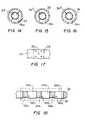
- FIGS. 14-16are sectional views of additional catheter embodiments.
- FIG. 17illustrates an inner face of a flexible catheter member
- FIG. 18depicts yet another embodiment of a catheter in accordance with the invention.
- FIG. 19is a table illustrating cooling performance of a catheter in accordance with the invention.
- FIG. 20is a sectional view of another catheter embodiment
- FIG. 21is a sectional view of a portion of the catheter of FIG. 20;
- FIG. 22is a detailed view of an area of the catheter portion illustrated in FIG. 21;
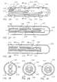
- FIG. 23is an illustration of yet another catheter embodiment
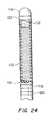
- FIG. 24depicts still another catheter embodiment
- FIG. 25illustrates yet another embodiment of the catheter
- FIG. 26is a sectional view of the catheter of FIG. 25 taken along line 26 — 26 ;
- FIG. 27illustrates yet still another embodiment of the catheter
- FIG. 28illustrates the catheter of FIG. 27 in a second configuration
- FIG. 29is a sectional view of the catheter of FIG. 28 taken along line 29 — 29 ;
- FIG. 30is a sectional view of the catheter of FIG. 28 taken along line 30 — 30 ;
- FIG. 31illustrates yet another embodiment of the catheter
- FIG. 32illustrates the catheter of FIG. 31 in a second configuration
- FIG. 33is a sectional view of the catheter of FIG. 32 taken along line 33 — 33 ;
- FIG. 34is a sectional view of the catheter of FIG. 32 taken along line 34 — 34 ;
- FIG. 35illustrates yet another embodiment of the catheter
- FIG. 36is a sectional view of yet another embodiment of the catheter.
- FIG. 37is a sectional view of the catheter of FIG. 36 after rotation
- FIG. 38illustrates yet another embodiment of the catheter
- FIG. 39illustrates the catheter of FIG. 38 in a second configuration.
- FIG. 1is a schematic illustration of a cryosurgical system in accordance with the invention.
- the systemincludes a supply of cryogenic or cooling fluid 10 in communication with the proximal end 12 of a flexible catheter 14 .
- a fluid controller 16is interposed or in-line between the cryogenic fluid supply 10 and the catheter 14 for regulating the flow of cryogenic fluid into the catheter in response to a controller command.
- Controller commandscan include programmed instructions, sensor signals, and manual user input.
- the fluid controller 16can be programmed or configured to increase and decrease the pressure of the fluid by predetermined pressure increments over predetermined time intervals.
- the fluid controller 16can be responsive to input from a foot pedal 18 to permit flow of the cryogenic fluid into the catheter 14 .
- One or more temperature sensors 20 in electrical communication with the controller 16can be provided to regulate or terminate the flow of cryogenic fluid into the catheter 14 when a predetermined temperature at a selected point or points on or within the catheter is/are obtained.
- a temperature sensorcan be placed at a point proximate the distal end 22 of the catheter and other temperature sensors 20 can be placed at spaced intervals between the distal end of the catheter and another point that is between the distal end and the proximal end.
- the cryogenic fluidcan be in a liquid or a gas state.
- An extremely low temperaturecan be achieved within the catheter, and more particularly on the surface of the catheter by cooling the fluid to a predetermined temperature prior to its introduction into the catheter, by allowing a liquid state cryogenic fluid to boil or vaporize, or by allowing a gas state cryogenic fluid to expand.
- Exemplary liquidsinclude chlorodifluoromethane, polydimethylsiloxane, ethyl alcohol, HFC's such as AZ-20 (a 50-50 mixture of difluoromethane & pentafluoroethane sold by Allied Signal), and CFC's such as DuPont's Freon.
- Exemplary gassesinclude nitrous oxide, and carbon dioxide.
- the catheter 14includes a flexible member 24 having a thermally-transmissive region 26 and a fluid path through the flexible member to the thermally-transmissive region.
- a fluid pathis also provided from the thermally-transmissive region to a point external to the catheter, such as the proximal end 12 .
- exemplary fluid pathscan be one or more channels defined by the flexible member 24 , and/or by one or more additional flexible members that are internal to the first flexible member 24 .
- a “thermally-transmissive region”is intended to broadly encompass any structure or region of the catheter 14 that readily conducts heat.
- thermally-transmissive region 26a metal structure exposed (directly or indirectly) to the cryogenic fluid path is considered a thermally-transmissive region 26 even if an adjacent polymeric or latex catheter portion also permits heat transfer, but to a much lesser extent than the metal.
- the thermally-transmissive region 26can be viewed as a relative term to compare the heat transfer characteristics of different catheter regions or structures.
- thermally-transmissive region 26can include a single, continuous, and uninterrupted surface or structure, it can also include multiple, discrete, thermally-transmissive structures that collectively define a thermally-transmissive region that is elongate or linear. Depending on the ability of the cryogenic system, or portions thereof, to handle given thermal loads, the ablation of an elongate tissue path can be performed in a single or multiple cycle process without having to relocate the catheter one or more times or drag it across tissue. Additional details of the thermally-transmissive region 26 and the thermal transfer process are described in greater detail below.
- the thermally-transmissive region 26 of the catheter 14is deformable.
- An exemplary deformationis from a linear configuration to an arcuate configuration and is accomplished using mechanical and/or electrical devices known to those skilled in the art.
- a wall portion of the flexible member 24can include a metal braid to make the catheter torqueable for overall catheter steering and placement.
- a cord, wire or cablecan be incorporated with, or inserted into, the catheter for deformation of the thermally transmissive region 26 .
- the cryogenic system of FIG. 1is better understood with reference to its use in an operative procedure as shown in FIG. 2 .
- the catheter 14is directed through a blood vessel 30 to a region within the heart; such as an atrial or ventricular chamber, where the lesion will be made.
- the thermally-transmissive region 26is placed proximate to the tissue to be ablated.
- the thermally-transmissive region of the cathetermay be deformed to conform to the curvature of the tissue before, during, or after placement against the tissue.
- the controller 16allows or causes cryogenic fluid to flow from the cryogenic fluid supply 10 to the fluid path in the catheter 14 and thence to the thermally-transmissive region 26 to ablate the desired area or to cold map along the same tissue area.
- a first conduitis concentric within a second conduit and cooling fluid travels to a thermally-transmissive region proximate a closed distal end of the catheter through a first conduit (fluid path) and is exhausted from the catheter through the second conduit (fluid path).
- FIGS. 3, 4 , 5 , 12 - 16 and 18illustrate embodiments of the catheter, or portions thereof, having two or more thermally-transmissive segments in a spaced-apart relationship.
- Each of the illustrated cathetersincludes a closed tip 32 that can include a thermally-transmissive material.
- thermally-transmissive elements 34are integral with a distal portion of a catheter.
- Each of the thermally-transmissive elements 34includes a first side or face 36 (shown in FIGS. 12 and 13) exposed to a cryogenic fluid path and cryogenic fluid (shown by arrows) and a second side or face 38 exposed to points exterior to the catheter.
- the first side 36 and/or second side 38 of any or all of the thermally-transmissive elements 34can be substantially flush with, recessed below, or protruding from the inner surface 40 and outer surface 42 of a portion of the catheter.
- the thermally-transmissive elements 34are separated by flexible portions of material 44 than can range from slightly less thermally-transmissive than the adjacent thermally-transmissive elements to substantially less thermally-transmissive than the adjacent elements.
- the thermally-transmissive elements 34are annular, cylindrical elements which are made of gold-plated copper or bronze.
- Thermocouples 35can be associated with one or more of the elements 34 and the tip 32 .
- the thermally-transmissive elements 34can be completely exposed, embedded, or a combination thereof along the full 360° of the catheter's circumference. In certain applications the thermally-transmissive elements traverse or define less than 360° of the catheter's circumference as shown in FIGS. 14-16 and as described below.
- each thermally-transmissive element 34The longitudinal width of each thermally-transmissive element 34 , the spacing between elements, the material thickness, and the material composition are matched with a selected cryogenic fluid, one or more cryogenic fluid delivery locations within the catheter and fluid delivery pressure to produce overlapping cold regions which produce a linear lesion.
- the embodiment illustrated in FIG. 4is substantially identical to the embodiment of FIG. 3, however, at least one of the thermally-transmissive elements 34 includes a first open end 46 that defines a first plane and a second open end 48 that defines a second plane, wherein the first and second planes intersect to give the annular elements a wedge-like appearance.
- a configurationpermits adjacent thermally-transmissive elements 34 to be positioned very closely together, but it can limit the possibilities for deforming the thermally-transmissive region 26 , which, in this embodiment, is flexible in the direction indicated by the arrow.
- the thermally-transmissive elements 34are substantially rigid and are separated and/or joined by a flexible material 44 .
- the thermally-transmissive elements 34are flexible and are interdigitated with either rigid or flexible segments.
- a metal bellowscan have enough stiffness to retain a selected shape after a deforming or bending step.
- the distal tip 32(or a portion thereof) can be deformable.
- FIG. 6illustrates a tip 32 having thermally-transmissive, flexible, bellows 50 .
- FIG. 7illustrates a catheter embodiment having an elongate, thermally-transmissive region 26 that includes a helical coil 52 at least partially embedded in the flexible member 24 .
- a first portion 54 of the helical coil 52is exposed to a fluid path within the flexible member 24 and a second portion 56 of the helical coil is exposed to the exterior of the flexible member.
- the first portion 54 of the coilcan be substantially flush with, recessed below, or protruding from an inner surface 58 of the flexible member 24 .
- the second portion 56 of the coil 52can be substantially flush with, recessed below, or protruding from an outer surface 60 of the flexible member 24 .
- the second portion 56 of the coil 52is exposed along only a portion of the outer circumference of the flexible member 24 to define a longitudinally-elongate, thermally-transmissive region 26 .
- This configurationcan be provided by eccentrically mating the helical coil 52 to the catheter so that the longitudinal axis of the coil and the longitudinal axis of the catheter are substantially parallel.
- the eccentric positioning of the coil 52provides excellent cooling performance because the surface area available for thermal exchange between the first portion 54 of coil and the cryogenic fluid is greater than the surface area available for thermal exchange between the second portion 56 of the coil and adjacent tissue where cooling power is delivered by each exposed coil portion to provide a linear lesion.
- FIG. 9an alternative embodiment is shown wherein a first portion 62 of the coil 52 is exposed around the entire circumference of the flexible member 24 , and a second portion 64 is exposed to a fluid path around the inner surface of the flexible member 24 . This is achieved by having the longitudinal axis of the helical coil 52 co-axial with the longitudinal axis of the catheter.
- the coil 52is solid. However, in other embodiments the coil can be an elongate, hollow, gas expansion chamber.
- FIG. 10illustrates a portion of a helical coil 52 that includes a passage that defines at least a portion of a fluid path through a flexible member of the catheter.
- the coil 52defines a first fluid path diameter at a fluid entry point 66 and a second fluid path diameter that is greater than the first fluid path diameter at a gas expansion or boiling location 68 .
- Gas escaping from a fluid exit point 70can be exhausted through an open central region of the coil and/or another passage through the flexible member 24 .
- FIG. 11illustrates an embodiment of the catheter wherein a continuous, elongate, thermally-transmissive strip 72 is longitudinally integrated with a flexible member 24 .
- the stripcan include a bellows-like structure. As described above with respect to other embodiments, a first portion of the strip can be substantially flush with, recessed below, or protrude from the outer surface of the flexible member. Similarly, a second portion of the strip can be substantially flush with, recessed below, or protrude from an inner surface of the flexible member.
- FIG. 12an embodiment of the catheter is illustrated having a second or inner flexible member 74 within a lumen of first or outer flexible member 24 , wherein the second flexible member defines a fluid path to the thermally-transmissive region 26 .
- the inner member 74can include a single opening 76 at or near the tip 32 . Cryogenic fluid is expelled from the opening 76 and returns to the proximal end of the catheter along a fluid path defined by the outer wall of the inner member 74 and the inner wall of the outer member 24 .
- This fluid path configurationis also partially illustrated in FIGS. 8, 9 , and 13 .
- FIG. 8 9 , and 13Alternatively, as also shown in FIG.
- the inner member 74can be provided with multiple openings 78 proximate to and/or aligned with the inner face of one or more thermally-transmissive elements 34 to achieve more uniform cooling across the entire elongate, thermally-transmissive region 26 .
- thermally-transmissive elements 34are arcuate and form complete and continuous 360 degree structures that traverse the complete circumference of the catheter, notwithstanding being flush with, depressed below, or raised above the outermost surface of the flexible member 24 .
- the arcuate elements 34 ′, 34 ′′, and 34 ′′′ illustrated in FIGS. 14-16respectively, traverse less than 360 degrees of the circumference of the first flexible member and do not form complete loops.
- element 34 ′defines an approximately 270 degree arc.
- the thermally-transmissive element 34 ′′defines an approximately 180 degree arc; and in FIG.
- the thermally-transmissive element 34 ′′′defines an approximately 90 degree arc.
- a cathetercan include combinations of element types, such as a complete ring or loop element, a 270 degree element and a 180 degree element as desired to define a thermally transmissive region.
- the bellows-like elementscan also be less than 360 degrees.
- the less than 360 degree arcuate elementsprovide unique functional benefits with respect to thermal transfer and flexibility of the thermally-transmissive region.
- the portion of the catheter between the opposing ends of element 34 ′, 34 ′′, 34 ′′′does not include a rigid structure, but rather only the resilient material of flexible member 24 , the thermally-transmissive region of the catheter can be more tightly curved (gap between ends inward and element facing outward) than it could with complete 360 degree structures, especially if the elements are relatively long longitudinally.
- the inner member 74can be adapted to direct cooling fluid at only the thermally transmissive element(s) and the shape and/or the number of openings for cooling fluid can be configured differently depending on the length of the arc defined by the thermally-transmissive element(s).
- FIG. 14illustrates an embodiment of the inner member having three openings opposing the thermally transmissive element 34 ′;
- FIG. 15illustrates two openings for a smaller arc; and
- FIG. 16discloses a single opening for an even smaller arc.
- a similar effectcan also be achieved by providing a non-circular 360 degree element or by eccentrically mounting a circular 360 degree element with respect to the flexible member, wherein a portion of the 360 degree element is embedded within the wall of the flexible member or otherwise insulated from the cryogenic fluid path in a manner similar to that shown in FIG. 8 .
- thermal transfer pins 80protruding from the inner face of a thermally-transmissive element 34 .
- the pinspermit thermal transfer through the flexible member 24 .
- the pinsare equally suitable for complete 360 degree element structures or less than 360 degree structures. Although only pins are shown on any geometric or surface means to increase heat transfer including but not limited to pins, irregularities, channels or surface modifications may be used.
- FIG. 18yet another embodiment of the catheter is shown wherein rigid metal rings 34 a-c are interdigitated with flexible segments 44 a-c to define a first flexible member and a thermally-transmissive region approximately one inch in length.
- a second flexible memberis concentric within the first flexible member and has an outlet for cryogenic fluid at its distal end.
- Thermocouples 82 a-ccan be associated with one or more of the rings 34 a-c.
- the thermal loading of a cooling systemcan be reduced by providing thermally-transmissive elements that span less than 360 degrees.
- the thermal loadingcan also be reduced by sequentially cooling the thermally-transmissive region.
- One way to sequentially coolis to modulate the pressure of the cooling fluid along the fluid path through the flexible member. This modulation can be performed by the fluid controller which can be programmed to increase and decrease the pressure of the fluid by predetermined pressure increments over predetermined time intervals.
- the cryogenic fluidis a liquid that provides cooling by changing phase from liquid to gas
- the change of pressurealters the physical location along the fluid path where the phase change takes place and concomitantly changes the point of coldest temperature along the thermally-transmissive region.
- varying the pressure of the fluidcan provide a moving ice-formation “front” along the catheter, enabling the creation of a linear lesion.
- a method of forming an elongate tissue lesioncan include the following steps using any of the above described catheters having an elongate, thermally-transmissive region.
- a cryogenic fluidis introduced into the flexible member at a first predetermined pressure.
- the pressure of the cryogenic fluidis incrementally increased within the flexible member until a second predetermined pressure is achieved.
- the pressure of the cryogenic fluid within the flexible membercan be decreased incrementally from the second predetermined pressure to the first predetermined pressure, wherein the steps of incrementally increasing and decreasing the pressure define a thermal cycle.
- from one to eight thermal cyclesare required to achieve a desired therapeutic effect.
- about ten increments of about five seconds in durationare selected and pressure is increased by about 20 to 40 pounds per square inch in each increment.
- an elongate lesioncan be created in less than 20 minutes.
- FIG. 19is a table that illustrates sequential cooling in a catheter as described above having a thermally-transmissive region that includes a tip and three elements or rings.
- the tableillustrates three tests conducted in a still bath at 37° C., using AZ-20 as the cryogenic fluid. Associated with each pressure increment are measured temperatures at the tip, first ring, second ring, and third ring.
- the shaded regionillustrates the sequential movement of a target temperature range (upper ⁇ 40's to low ⁇ 50's) in response to a change in pressure. Although values are only provided for three rings, a similar effect and pattern is obtained with more than three rings or elements.
- thermally-transmissive portion of another embodiment of a medical device or structure such as a catheteris illustrated in a sectional view.
- the structurecan include an inner passage or lumen as described above with respect to other embodiments, but which is not shown in this illustration for purposes of clarity.
- the illustrated portionis the outer passage or lumen that defines an elongate ablation region.
- Thermally-transmissive elements 84such as gold plated copper, are joined to adjacent elements by resilient connecting elements 86 , such as a stainless steel springs welded to the ends of the elements 84 .
- a resilient bio-compatible material 88covers the connecting elements 86 and the interstices between adjacent thermally-transmissive elements.
- the material 88is vulcanized silicone. It should be noted in the illustration that the surface of the elements 84 is contiguous and co-planar with the material 88 to provide a smooth outer surface.
- FIG. 21illustrates a single thermally-transmissive element 84 having reduced diameter ends 90 and 92 .
- the wider central portion 94provides an expansion chamber for gas (shown by arrows) exiting an apertured inner passage 96 .
- FIG. 22shows additional detail of the end 90 of the element 84 .
- the end 90is textured, such as by providing serrations 98 , to provide a good adhesion surface for the material 88 .
- FIG. 23a thermally-transmissive portion of yet another embodiment of a flexible cryogenic structure is illustrated in a sectional view.
- an inner, apertured structure 100has a flat wire 102 wrapped around it in a spiral manner.
- Thermally-transmissive segments 104are disposed upon the wire 102 in a spaced-apart relationship, and a flexible, bio-compatible material 106 fills the interstices between segments 104 .
- a thermocouple 108can be associated with each segment 104 .
- a wire 109connects the thermocouple 108 to instrumentation near the proximal end of the structure.
- the exterior surface of the structureis smooth, and the structure can include 3 to 12 segments 104 .
- the inner structure 100is made of PTFE, the material 106 is 33 D Pebax, and the wire 102 is stainless steel or Nitinol.
- An apertured inner passage(similar to that shown in FIG. 21) is placed within the structure.
- FIG. 24illustrates still another embodiment of a cryogenic cooling structure that includes a surface or wall 110 including a polymer or elastomer that is thin enough to permit thermal transfer.
- a polymer or elastomerthat is thin enough to permit thermal transfer.
- polyamide, PET, or PTFEhaving a thickness of a typical angioplasty balloon or less (below 0.006 inches) provides acceptable thermal transfer.
- the thinness of the wall 110allows it to readily collapse or otherwise deform under vacuum or near vacuum conditions applied to evacuate fluid/gas from the structure.
- the structureis provided with one or more supporting elements 112 such as a spring.
- the cooling structureis illustrated in association with a catheter 114 having a closed distal tip 116 and mono or bipolar ECG rings 118 , 120 , 122 .
- the thermally-transmissive regionis approximately 30 mm in length and is effective for thermal transfer over its entire circumference. However, as illustrated in FIG. 11, the thermally-transmissive region can be confined to specific region(s
- an embodiment of the catheteris illustrated having three flexible members or injection tubes 210 , 211 and 212 disposed within a first or outer flexible member 200 .
- the inner flexible members 210 , 211 and 212are arranged in a staggered configuration within the outer flexible member 200 .
- staggeredmay be used to designate both a linearly/axially staggered configuration or alternatively, a rotationally staggered configuration.
- the flexible members 210 , 211 and 212thus define multiple staggered fluid paths within the outer member 200 .
- thermocouples 204 disposed along the outer surface of the outer flexible member 200may be integrated with an internal feedback loop to provide independent and variable regulation of these freeze zones.
- the first inner member 210includes at least one opening 214 positioned proximate an electrode ring member 207 . Cryogenic fluid is expelled from the opening 214 and returns to the proximal end of the catheter along a fluid path defined by the inner wall 218 of the outer member 200 , as shown in FIG. 26 .
- the second inner member 211includes at least one opening 215 positioned proximate a second electrode ring member 208 . Cryogenic fluid is also expelled from the opening 215 and returns to the proximal end of the catheter along the fluid path defined by the inner wall 218 of the outer member 200 .
- the third inner member 212includes at least one opening 216 positioned proximate a third electrode ring member 209 .
- the cathetercan be provided with only two inner members, or four or more inner members, not shown, disposed within the outer member.
- the inner memberswould have one or more openings proximate to and/or aligned with the inner face of one or more transmissive elements, as described earlier herein, to achieve different regions of freeze zones across the entire elongate member.
- all the staggered inner membersmay be simultaneously provided with cryogenic fluid to create a linear lesion for selected applications.
- the flow of cooling fluid along the fluid paths through the flexible memberscan also be alternated in any number of patterns among the multiple inner members to provide a desired cooling pattern such as a discontinuous or a continuous lesion across the entire catheter.
- a catheter with a plurality of thermally conductive electrode ringswould have an underlying injection tube or tubes controlling the release of cryogenic fluid to each electrode.
- a cathetercould be placed in the coronary sinus or endocardially along the atrioventricular junction.
- an electrogram of interestis located using a specific electrode ring on the catheter.
- Coldmappingmay be performed on the selected location to confirm the correctness of the location. Once, confirmed, the area is cryoablated using the same electrode ring.
- the same embodiments and others described hereinare equally suited to other organs besides the heart and/or any body portion that would benefit from the application of thermal energy.
- an embodiment of the catheteris illustrated having an outer member 220 with a fixed injection tube 230 disposed within a slidable sheath or overtube 240 therein.
- the injection tube and overtubeare shown spaced apart for illustrative purposes only.
- the injection tubeis sized so that an outer surface of the injection tube engages an inner surface of the overtube while still allowing one member to slide or rotate relative to the other.
- the fixed injection tube 230has multiple openings 232 , 234 formed thereon and the slidable overtube also has multiple openings or ports 242 , 244 formed thereon.
- opening 232 on the injection tube 230coincides or is aligned with opening 242 on the slidable overtube 240 .
- any fluid exiting the injection tube 230 from opening 232is able to escape through opening 242 .
- opening 232is covered or blocked by the surface of overtube 240 as now shown in FIG. 28 .
- opening 234 of injection tube 230is aligned with opening 244 of overtube 240 .
- opening 242is not aligned with any opening formed on the surface of injection tube 230 .
- the slidable overtubeis positionable in any number of positions relative to the fixed injection tube.
- the overtubemay also be used to partially cover the openings on the injection tube to provide for a limited or controlled flow of cryogenic fluid.
- cryogenic fluidis expelled from the opening and returns to the proximal end of the catheter along a fluid path defined by the inner wall 226 of the outer member 220 .
- the non-aligned openingwill not expel fluid since the opening will be blocked.
- the injection tube and overtubecan be provided with three or more openings to achieve multiple cooling/freeze zones along the length of the catheter.
- an embodiment of the catheteris illustrated having a slidable injection tube 260 disposed within a fixed sheath or overtube 270 .
- both the injection tube 260 and overtube 270are disposed within a flexible outer member 250 .
- the slidable injection tube 260has multiple openings 262 , 264 formed thereon which allows for the release of cryogenic fluid.
- the fixed overtube 270also has multiple perforations or openings 272 , 274 formed thereon which allows for the differential release of fluid as described in more detail below.
- the injection tubemay be further provided with a thermistor 254 disposed proximate the distal end of the tube to provide thermistor feedback.
- the openingscan be controlled by miniaturized means such as micro or nanovalves.
- opening 262 of the injection tube 260coincides or is aligned with opening 274 of the fixed overtube 270 .
- opening 262is then aligned with corresponding opening 272 on the overtube 270 in FIG. 32 .
- openings 262 , 264 of injection tube 260are aligned with openings 272 , 274 of overtube 270 .
- the injection tube 260is positionable in any number of locations relative to the fixed overtube 270 .
- cryogenic fluidis expelled from the openings and returns to the proximal end of the catheter along a fluid path defined by an inner wall 256 of the outer member 250 .
- the injection tube 260 and overtube 270can be provided with multiple openings proximate to and/or aligned with the inner face of one or more thermally-transmissive elements as described earlier herein to achieve more uniform cooling across the entire elongate, thermally-transmissive region.
- an embodiment of the catheteris illustrated having an outer member 280 with an injection tube 290 with multiple opposed openings 292 - 297 formed therein.
- Either the injection tube 290 or the overtube 300may be slidable in a longitudinal plane to expose and/or cover one or more of the opposed openings on the injection tube 290 .
- openings 294 , 295 formed on the injection tube 290are aligned with openings 302 , 303 formed on the overtube 230 .
- the injection tubemay be positioned in a forwardmost position, not shown, to expose openings on the injection tube proximate the tip of the catheter. In this configuration, the injection tube would provide fluid to cool the area around the tip of the catheter.
- electrode rings as shown in FIG. 25may be provided along the outer surface of any of the outer members.
- the electrodeswould serve both as electrical conductors and as a thermal transmitter at each location.
- the catheterhas one or more rotatable members disposed within a flexible outer member 310 .
- the catheterincludes an overtube member 312 and an injection tube member 314 , one or both of which are rotatable with respect to one another.
- the injection tube 314is rotatable relative to the fixed overtube 312 .
- the injection tube 314may be rotatable in either or both a clockwise and counterclockwise direction as indicated by arrows 320 and 322 .
- opening 316 formed on the overtube 312aligns with an opening 318 formed on the injection tube 314 .
- the opening 318 on the injection tube 314is placed out of alignment with the opening 316 formed on overtube 312 , as shown in FIG. 37 .
- the injection tube 314may be fixed in the catheter while the overtube 312 is rotatable.
- both the injection tube and overtubemay both be rotatable.
- the injection tube and/or the overtubeare rotatable and slidable within the outer member.
- the slidable and rotatable inner and outer tubesmay have openings so arranged as to allow the fluid releasing openings to be in a variety of open and closed configurations with a minimum of relational movement between the tubes.
- an outer member 330has disposed therein one slidably disposed inner tube 336 which has openings 338 formed thereon in a constant sequence, and a matching slidably disposed outer tube 332 which has openings 334 formed thereon in a constant sequence of slightly different length or intervals.
- small linear relational movementsbring the openings on the outer tube 332 and the inner tube 336 into an overlapping configuration.
- openings as shown and described hereinmay be so shaped as to allow additional control of fluid release.
- an outer holecould be tear-shaped and match up with an inner opening that is tear-shaped rotationally aligned 180° oppositely not shown. As the two narrow ends begin to overlap with slidable motion, a tiny aperture is created. With further slidable motion in the same direction, larger areas of the two openings overlap and larger volumes of cryogenic fluid can be released.
- the devices as shownare not to be limited to catheters but should be viewed more broadly as cryogenic structures or portions thereof. It is therefore understood that, within the scope of the appended claims, the present invention may be practiced otherwise than as specifically described hereinabove. All references cited herein are expressly incorporated by reference in their entirety.
Landscapes
- Health & Medical Sciences (AREA)
- Life Sciences & Earth Sciences (AREA)
- Surgery (AREA)
- Veterinary Medicine (AREA)
- General Health & Medical Sciences (AREA)
- Nuclear Medicine, Radiotherapy & Molecular Imaging (AREA)
- Biomedical Technology (AREA)
- Heart & Thoracic Surgery (AREA)
- Public Health (AREA)
- Animal Behavior & Ethology (AREA)
- Engineering & Computer Science (AREA)
- Hematology (AREA)
- Pulmonology (AREA)
- Anesthesiology (AREA)
- Biophysics (AREA)
- Otolaryngology (AREA)
- Medical Informatics (AREA)
- Molecular Biology (AREA)
- Surgical Instruments (AREA)
Abstract
Description
Claims (7)
Priority Applications (6)
| Application Number | Priority Date | Filing Date | Title |
|---|---|---|---|
| US10/050,452US6669689B2 (en) | 1997-02-27 | 2002-01-16 | Cryosurgical catheter |
| US10/346,032US6913604B2 (en) | 1997-02-27 | 2003-01-16 | Cryosurgical catheter |
| US11/224,370US7753905B2 (en) | 1997-02-27 | 2005-09-12 | Cryosurgical catheter |
| US12/791,985US7914526B2 (en) | 1997-02-27 | 2010-06-02 | Cryosurgical catheter |
| US12/792,376US8043284B2 (en) | 1997-02-27 | 2010-06-02 | Cryosurgical catheter |
| US13/238,607US8585690B2 (en) | 1997-02-27 | 2011-09-21 | Cryosurgical catheter |
Applications Claiming Priority (5)
| Application Number | Priority Date | Filing Date | Title |
|---|---|---|---|
| US08/807,382US5899898A (en) | 1997-02-27 | 1997-02-27 | Cryosurgical linear ablation |
| US08/893,825US5899899A (en) | 1997-02-27 | 1997-07-11 | Cryosurgical linear ablation structure |
| US09/201,071US6235019B1 (en) | 1997-02-27 | 1998-11-30 | Cryosurgical catheter |
| US09/845,535US6629972B2 (en) | 1997-02-27 | 2001-04-30 | Cryosurgical catheter |
| US10/050,452US6669689B2 (en) | 1997-02-27 | 2002-01-16 | Cryosurgical catheter |
Related Parent Applications (1)
| Application Number | Title | Priority Date | Filing Date |
|---|---|---|---|
| US09/845,535ContinuationUS6629972B2 (en) | 1997-02-27 | 2001-04-30 | Cryosurgical catheter |
Related Child Applications (2)
| Application Number | Title | Priority Date | Filing Date |
|---|---|---|---|
| US10/346,032Continuation-In-PartUS6913604B2 (en) | 1997-02-27 | 2003-01-16 | Cryosurgical catheter |
| US10/657,922ContinuationUS6942659B2 (en) | 1997-02-27 | 2003-09-09 | Cryosurgical catheter |
Publications (2)
| Publication Number | Publication Date |
|---|---|
| US20020062122A1 US20020062122A1 (en) | 2002-05-23 |
| US6669689B2true US6669689B2 (en) | 2003-12-30 |
Family
ID=46278707
Family Applications (6)
| Application Number | Title | Priority Date | Filing Date |
|---|---|---|---|
| US10/050,452Expired - LifetimeUS6669689B2 (en) | 1997-02-27 | 2002-01-16 | Cryosurgical catheter |
| US10/657,922Expired - LifetimeUS6942659B2 (en) | 1997-02-27 | 2003-09-09 | Cryosurgical catheter |
| US11/224,370Expired - Fee RelatedUS7753905B2 (en) | 1997-02-27 | 2005-09-12 | Cryosurgical catheter |
| US12/791,985Expired - Fee RelatedUS7914526B2 (en) | 1997-02-27 | 2010-06-02 | Cryosurgical catheter |
| US12/792,376Expired - Fee RelatedUS8043284B2 (en) | 1997-02-27 | 2010-06-02 | Cryosurgical catheter |
| US13/238,607Expired - Fee RelatedUS8585690B2 (en) | 1997-02-27 | 2011-09-21 | Cryosurgical catheter |
Family Applications After (5)
| Application Number | Title | Priority Date | Filing Date |
|---|---|---|---|
| US10/657,922Expired - LifetimeUS6942659B2 (en) | 1997-02-27 | 2003-09-09 | Cryosurgical catheter |
| US11/224,370Expired - Fee RelatedUS7753905B2 (en) | 1997-02-27 | 2005-09-12 | Cryosurgical catheter |
| US12/791,985Expired - Fee RelatedUS7914526B2 (en) | 1997-02-27 | 2010-06-02 | Cryosurgical catheter |
| US12/792,376Expired - Fee RelatedUS8043284B2 (en) | 1997-02-27 | 2010-06-02 | Cryosurgical catheter |
| US13/238,607Expired - Fee RelatedUS8585690B2 (en) | 1997-02-27 | 2011-09-21 | Cryosurgical catheter |
Country Status (1)
| Country | Link |
|---|---|
| US (6) | US6669689B2 (en) |
Cited By (68)
| Publication number | Priority date | Publication date | Assignee | Title |
|---|---|---|---|---|
| US20040064152A1 (en)* | 2001-09-27 | 2004-04-01 | Roni Zvuloni | Device, system, and method for cryosurgical treatment of cardiac arrhythmia |
| US20040243117A1 (en)* | 2002-12-11 | 2004-12-02 | Lentz David J. | Catheter system for performing a single step cryoablation |
| US20040243118A1 (en)* | 2001-06-01 | 2004-12-02 | Ayers Gregory M. | Device and method for positioning a catheter tip for creating a cryogenic lesion |
| US20050240117A1 (en)* | 2001-09-27 | 2005-10-27 | Galil Medical Ltd. | Thermal sensing device for thermal mapping of a body conduit |
| US20050283146A1 (en)* | 2004-06-17 | 2005-12-22 | Lentz David J | Thermally extended spiral cryotip for a cryoablation catheter |
| US7361168B2 (en) | 2004-04-21 | 2008-04-22 | Acclarent, Inc. | Implantable device and methods for delivering drugs and other substances to treat sinusitis and other disorders |
| US7410480B2 (en) | 2004-04-21 | 2008-08-12 | Acclarent, Inc. | Devices and methods for delivering therapeutic substances for the treatment of sinusitis and other disorders |
| US20080306475A1 (en)* | 2007-06-08 | 2008-12-11 | Lentz David J | Cryo-applicator cross-section configuration |
| US7720521B2 (en) | 2004-04-21 | 2010-05-18 | Acclarent, Inc. | Methods and devices for performing procedures within the ear, nose, throat and paranasal sinuses |
| US8080000B2 (en) | 2004-04-21 | 2011-12-20 | Acclarent, Inc. | Methods and apparatus for treating disorders of the ear nose and throat |
| US8088101B2 (en) | 2004-04-21 | 2012-01-03 | Acclarent, Inc. | Devices, systems and methods for treating disorders of the ear, nose and throat |
| US20120010605A1 (en)* | 1997-02-27 | 2012-01-12 | Medtronic Cryocath Lp | Cryosurgical catheter |
| US8100933B2 (en) | 2002-09-30 | 2012-01-24 | Acclarent, Inc. | Method for treating obstructed paranasal frontal sinuses |
| US8114113B2 (en) | 2005-09-23 | 2012-02-14 | Acclarent, Inc. | Multi-conduit balloon catheter |
| US8118757B2 (en) | 2007-04-30 | 2012-02-21 | Acclarent, Inc. | Methods and devices for ostium measurement |
| US8142422B2 (en) | 2004-04-21 | 2012-03-27 | Acclarent, Inc. | Devices, systems and methods for diagnosing and treating sinusitis and other disorders of the ears, nose and/or throat |
| US8146400B2 (en) | 2004-04-21 | 2012-04-03 | Acclarent, Inc. | Endoscopic methods and devices for transnasal procedures |
| US8172828B2 (en) | 2004-04-21 | 2012-05-08 | Acclarent, Inc. | Apparatus and methods for dilating and modifying ostia of paranasal sinuses and other intranasal or paranasal structures |
| US8182432B2 (en) | 2008-03-10 | 2012-05-22 | Acclarent, Inc. | Corewire design and construction for medical devices |
| US8190389B2 (en) | 2006-05-17 | 2012-05-29 | Acclarent, Inc. | Adapter for attaching electromagnetic image guidance components to a medical device |
| US8388642B2 (en) | 2005-01-18 | 2013-03-05 | Acclarent, Inc. | Implantable devices and methods for treating sinusitis and other disorders |
| US8414473B2 (en) | 2004-04-21 | 2013-04-09 | Acclarent, Inc. | Methods and apparatus for treating disorders of the ear nose and throat |
| US8435290B2 (en) | 2009-03-31 | 2013-05-07 | Acclarent, Inc. | System and method for treatment of non-ventilating middle ear by providing a gas pathway through the nasopharynx |
| US8439687B1 (en) | 2006-12-29 | 2013-05-14 | Acclarent, Inc. | Apparatus and method for simulated insertion and positioning of guidewares and other interventional devices |
| US8485199B2 (en) | 2007-05-08 | 2013-07-16 | Acclarent, Inc. | Methods and devices for protecting nasal turbinate during surgery |
| US8702626B1 (en) | 2004-04-21 | 2014-04-22 | Acclarent, Inc. | Guidewires for performing image guided procedures |
| US8715169B2 (en) | 2004-04-21 | 2014-05-06 | Acclarent, Inc. | Devices, systems and methods useable for treating sinusitis |
| US8740929B2 (en) | 2001-02-06 | 2014-06-03 | Acclarent, Inc. | Spacing device for releasing active substances in the paranasal sinus |
| US8747389B2 (en) | 2004-04-21 | 2014-06-10 | Acclarent, Inc. | Systems for treating disorders of the ear, nose and throat |
| US8764729B2 (en) | 2004-04-21 | 2014-07-01 | Acclarent, Inc. | Frontal sinus spacer |
| US20140276619A1 (en)* | 2013-03-15 | 2014-09-18 | The Board Of Trustees Of The University Of Illinois | Extendable Intravenous Catheter |
| US8864787B2 (en) | 2004-04-21 | 2014-10-21 | Acclarent, Inc. | Ethmoidotomy system and implantable spacer devices having therapeutic substance delivery capability for treatment of paranasal sinusitis |
| US8894614B2 (en) | 2004-04-21 | 2014-11-25 | Acclarent, Inc. | Devices, systems and methods useable for treating frontal sinusitis |
| US8915908B2 (en) | 2009-03-20 | 2014-12-23 | Atricure, Inc. | Cryogenic probe |
| US8932276B1 (en) | 2004-04-21 | 2015-01-13 | Acclarent, Inc. | Shapeable guide catheters and related methods |
| US8951225B2 (en) | 2005-06-10 | 2015-02-10 | Acclarent, Inc. | Catheters with non-removable guide members useable for treatment of sinusitis |
| US8979888B2 (en) | 2008-07-30 | 2015-03-17 | Acclarent, Inc. | Paranasal ostium finder devices and methods |
| US9072626B2 (en) | 2009-03-31 | 2015-07-07 | Acclarent, Inc. | System and method for treatment of non-ventilating middle ear by providing a gas pathway through the nasopharynx |
| US9089258B2 (en) | 2004-04-21 | 2015-07-28 | Acclarent, Inc. | Endoscopic methods and devices for transnasal procedures |
| US9101384B2 (en) | 2004-04-21 | 2015-08-11 | Acclarent, Inc. | Devices, systems and methods for diagnosing and treating sinusitis and other disorders of the ears, Nose and/or throat |
| US9107574B2 (en) | 2004-04-21 | 2015-08-18 | Acclarent, Inc. | Endoscopic methods and devices for transnasal procedures |
| US9155492B2 (en) | 2010-09-24 | 2015-10-13 | Acclarent, Inc. | Sinus illumination lightwire device |
| US9265407B2 (en) | 2004-04-21 | 2016-02-23 | Acclarent, Inc. | Endoscopic methods and devices for transnasal procedures |
| US9351750B2 (en) | 2004-04-21 | 2016-05-31 | Acclarent, Inc. | Devices and methods for treating maxillary sinus disease |
| US9399121B2 (en) | 2004-04-21 | 2016-07-26 | Acclarent, Inc. | Systems and methods for transnasal dilation of passageways in the ear, nose or throat |
| US9433437B2 (en) | 2013-03-15 | 2016-09-06 | Acclarent, Inc. | Apparatus and method for treatment of ethmoid sinusitis |
| US9459044B1 (en)* | 2013-03-15 | 2016-10-04 | Harvest Right, LLC | Freeze drying methods and apparatuses |
| US9468362B2 (en) | 2004-04-21 | 2016-10-18 | Acclarent, Inc. | Endoscopic methods and devices for transnasal procedures |
| US9629684B2 (en) | 2013-03-15 | 2017-04-25 | Acclarent, Inc. | Apparatus and method for treatment of ethmoid sinusitis |
| US9820688B2 (en) | 2006-09-15 | 2017-11-21 | Acclarent, Inc. | Sinus illumination lightwire device |
| US10076384B2 (en) | 2013-03-08 | 2018-09-18 | Symple Surgical, Inc. | Balloon catheter apparatus with microwave emitter |
| US10188413B1 (en)* | 2004-04-21 | 2019-01-29 | Acclarent, Inc. | Deflectable guide catheters and related methods |
| US10206821B2 (en) | 2007-12-20 | 2019-02-19 | Acclarent, Inc. | Eustachian tube dilation balloon with ventilation path |
| US10524814B2 (en) | 2009-03-20 | 2020-01-07 | Acclarent, Inc. | Guide system with suction |
| US11065061B2 (en) | 2004-04-21 | 2021-07-20 | Acclarent, Inc. | Systems and methods for performing image guided procedures within the ear, nose, throat and paranasal sinuses |
| US11517187B2 (en)* | 2017-04-13 | 2022-12-06 | The Regents Of The University Of California | System and method for endoscope locomotion and shaping |
| US11529502B2 (en) | 2004-04-21 | 2022-12-20 | Acclarent, Inc. | Apparatus and methods for dilating and modifying ostia of paranasal sinuses and other intranasal or paranasal structures |
| US11744257B1 (en) | 2018-10-19 | 2023-09-05 | Harvest Right, LLC | Freeze-drying methods including vacuum freezing |
| US11998262B1 (en) | 2020-04-09 | 2024-06-04 | Neurent Medical Limited | Systems and methods for improving sleep with therapeutic nasal treatment |
| US12225914B1 (en) | 2023-05-08 | 2025-02-18 | Harvest Right, LLC | Freeze dryers and drying processes for materials with low water content |
| US12268433B2 (en) | 2015-05-12 | 2025-04-08 | National University Of Ireland, Galway | Devices for therapeutic nasal neuromodulation and associated methods and systems |
| US12279808B2 (en) | 2018-12-11 | 2025-04-22 | Neurent Medical Limited | Systems and methods for therapeutic nasal neuromodulation |
| US12336750B2 (en) | 2016-12-22 | 2025-06-24 | Aerin Medical Inc. | Soft palate treatment |
| US12357817B2 (en) | 2021-04-06 | 2025-07-15 | Aerin Medical Inc. | Nasal neuromodulation devices and methods |
| US12357378B2 (en) | 2011-06-14 | 2025-07-15 | Aerin Medical Inc. | Treating upper airway nerve tissue |
| US12364532B2 (en) | 2011-06-14 | 2025-07-22 | Aerin Medical Inc. | Methods and devices to treat nasal airways |
| US12369963B1 (en) | 2011-06-14 | 2025-07-29 | Aerin Medical Inc. | Methods and devices to treat nasal airways |
| US12433837B2 (en) | 2005-07-22 | 2025-10-07 | The Foundry, Llc | Systems and methods for delivery of a therapeutic agent |
Families Citing this family (61)
| Publication number | Priority date | Publication date | Assignee | Title |
|---|---|---|---|---|
| US7004936B2 (en) | 2000-08-09 | 2006-02-28 | Cryocor, Inc. | Refrigeration source for a cryoablation catheter |
| US6955673B2 (en)* | 2002-08-16 | 2005-10-18 | Cryocor, Inc. | Heat transfer segment for a cryoablation catheter |
| US20040034344A1 (en)* | 2002-08-16 | 2004-02-19 | Eric Ryba | Tip pressure monitoring for cryoablation catheters |
| US7258690B2 (en) | 2003-03-28 | 2007-08-21 | Relievant Medsystems, Inc. | Windowed thermal ablation probe |
| US6907884B2 (en) | 2002-09-30 | 2005-06-21 | Depay Acromed, Inc. | Method of straddling an intraosseous nerve |
| US8361067B2 (en) | 2002-09-30 | 2013-01-29 | Relievant Medsystems, Inc. | Methods of therapeutically heating a vertebral body to treat back pain |
| US7037319B2 (en)* | 2002-10-15 | 2006-05-02 | Scimed Life Systems, Inc. | Nanotube paper-based medical device |
| US20040199052A1 (en) | 2003-04-01 | 2004-10-07 | Scimed Life Systems, Inc. | Endoscopic imaging system |
| US6981382B2 (en)* | 2003-07-24 | 2006-01-03 | Cryocor, Inc. | Distal end for cryoablation catheters |
| US6926711B2 (en)* | 2003-07-30 | 2005-08-09 | Cryocor, Inc. | Articulating catheter for cryoablation with reduced diameter section |
| US20050027289A1 (en)* | 2003-07-31 | 2005-02-03 | Thomas Castellano | Cryoablation systems and methods |
| US7070594B2 (en)* | 2004-02-10 | 2006-07-04 | Cryocor, Inc. | System and method for assessing ice ball formation during a cryoablation procedure |
| US20050198972A1 (en)* | 2004-03-10 | 2005-09-15 | Lentz David J. | Pressure-temperature control for a cryoablation catheter system |
| US7156840B2 (en)* | 2004-06-29 | 2007-01-02 | Cryocor, Inc. | Pressure monitor for cryoablation catheter |
| US7357797B2 (en)* | 2004-06-30 | 2008-04-15 | Cryocor, Inc. | System and method for varying return pressure to control tip temperature of a cryoablation catheter |
| US7163535B2 (en)* | 2004-06-30 | 2007-01-16 | Cryocor, Inc. | System for detecting leaks and occlusions in a cryoablation catheter |
| US7425211B2 (en)* | 2006-08-03 | 2008-09-16 | Arbel Medical Ltd. | Cryogenic probe for treating enlarged volume of tissue |
| US7803154B2 (en)* | 2006-08-03 | 2010-09-28 | Arbel Medical Ltd. | Cryogenic probe for treating enlarged volume of tissue |
| FR2916625B1 (en)* | 2007-05-31 | 2010-08-20 | Phakos | CRYOGENIC DEVICE FOR SURGICAL USE |
| WO2009079545A1 (en)* | 2007-12-19 | 2009-06-25 | Boston Scientific Scimed, Inc. | Structure for use as part of a medical device |
| WO2009094511A1 (en)* | 2008-01-24 | 2009-07-30 | Boston Scientific Scimed, Inc. | Structure for use as part of a medical device |
| DE102008010477A1 (en)* | 2008-02-21 | 2009-09-03 | Erbe Elektromedizin Gmbh | Cryosurgical instrument |
| EP2252226B1 (en)* | 2008-03-12 | 2017-11-15 | AFreeze GmbH | Ablation system |
| US20090240109A1 (en)* | 2008-03-24 | 2009-09-24 | Boston Scientific Scimed, Inc. | Flexible endoscope with core member |
| WO2009128014A1 (en) | 2008-04-16 | 2009-10-22 | Arbel Medical Ltd | Cryosurgical instrument with enhanced heat exchange |
| US8945106B2 (en)* | 2008-07-03 | 2015-02-03 | Steve Arless | Tip design for cryogenic probe with inner coil injection tube |
| US8845627B2 (en) | 2008-08-22 | 2014-09-30 | Boston Scientific Scimed, Inc. | Regulating pressure to lower temperature in a cryotherapy balloon catheter |
| US10028753B2 (en) | 2008-09-26 | 2018-07-24 | Relievant Medsystems, Inc. | Spine treatment kits |
| CA2737374C (en) | 2008-09-26 | 2017-03-28 | Relievant Medsystems, Inc. | Systems and methods for navigating an instrument through bone |
| US8382746B2 (en) | 2008-11-21 | 2013-02-26 | C2 Therapeutics, Inc. | Cryogenic ablation system and method |
| US7967814B2 (en) | 2009-02-05 | 2011-06-28 | Icecure Medical Ltd. | Cryoprobe with vibrating mechanism |
| US8162812B2 (en) | 2009-03-12 | 2012-04-24 | Icecure Medical Ltd. | Combined cryotherapy and brachytherapy device and method |
| US7967815B1 (en) | 2010-03-25 | 2011-06-28 | Icecure Medical Ltd. | Cryosurgical instrument with enhanced heat transfer |
| US9936996B2 (en)* | 2010-03-30 | 2018-04-10 | Medtronic ATS Medical, Inc. | Cryoprobe having internal warming fluid capabilities |
| US7938822B1 (en) | 2010-05-12 | 2011-05-10 | Icecure Medical Ltd. | Heating and cooling of cryosurgical instrument using a single cryogen |
| US8080005B1 (en) | 2010-06-10 | 2011-12-20 | Icecure Medical Ltd. | Closed loop cryosurgical pressure and flow regulated system |
| US9220555B2 (en) | 2010-10-28 | 2015-12-29 | Medtronic Ablation Frontiers Llc | Cryo-ablation device with deployable injection tube |
| US20120109118A1 (en)* | 2010-10-29 | 2012-05-03 | Medtronic Ablation Frontiers Llc | Cryogenic-radiofrequency ablation system |
| US9492633B2 (en)* | 2011-09-30 | 2016-11-15 | Zoll Circulation, Inc. | Heat exchange catheter and their methods of manufacture and use |
| US9314588B2 (en) | 2011-10-28 | 2016-04-19 | Medtronic Cryocath Lp | Systems and methods for variable injection flow |
| AU2012362524B2 (en) | 2011-12-30 | 2018-12-13 | Relievant Medsystems, Inc. | Systems and methods for treating back pain |
| US10588691B2 (en) | 2012-09-12 | 2020-03-17 | Relievant Medsystems, Inc. | Radiofrequency ablation of tissue within a vertebral body |
| WO2014071161A1 (en) | 2012-11-05 | 2014-05-08 | Relievant Medsystems, Inc. | System and methods for creating curved paths through bone and modulating nerves within the bone |
| US9381055B2 (en)* | 2013-03-13 | 2016-07-05 | Cryofocus Medtech (Shanghai) Co. Ltd. | Therapeutic cryoablation system |
| FR3006594A1 (en)* | 2013-06-11 | 2014-12-12 | Sorin Crm Sas | IMPLANTABLE MICROSONDE FOR DETECTION / STIMULATION INCORPORATING AN ANTI-INFLAMMATORY AGENT |
| US9724151B2 (en) | 2013-08-08 | 2017-08-08 | Relievant Medsystems, Inc. | Modulating nerves within bone using bone fasteners |
| JP6402317B2 (en)* | 2013-11-01 | 2018-10-10 | ペンタックス・オブ・アメリカ・インコーポレイテッドPentax Of America, Inc. | Frozen balloon ablation system |
| US10441338B2 (en)* | 2014-01-14 | 2019-10-15 | Medtronic Cryocath Lp | Balloon catheter with fluid injection elements |
| US9730755B2 (en) | 2014-01-31 | 2017-08-15 | Medtronic Cryocath Lp | Medical device with adjustable flexibility |
| US11033319B2 (en) | 2014-12-01 | 2021-06-15 | Vesica E.K. Therapeutics Ltd. | Device and method for ablative treatment of targeted areas within a body lumen |
| US9414878B1 (en) | 2015-05-15 | 2016-08-16 | C2 Therapeutics, Inc. | Cryogenic balloon ablation system |
| JP7021113B2 (en) | 2016-05-20 | 2022-02-16 | ペンタックス・オブ・アメリカ・インコーポレイテッド | Cryogenic excision system with rotatable and translatable catheter |
| AU2020346827A1 (en) | 2019-09-12 | 2022-03-31 | Relievant Medsystems, Inc. | Systems and methods for tissue modulation |
| US11633224B2 (en) | 2020-02-10 | 2023-04-25 | Icecure Medical Ltd. | Cryogen pump |
| US12082876B1 (en) | 2020-09-28 | 2024-09-10 | Relievant Medsystems, Inc. | Introducer drill |
| EP4268150A4 (en) | 2020-12-22 | 2024-12-18 | Relievant Medsystems, Inc. | PREDICTION OF CANDIDATES FOR SPINAL NEUROMODULATION |
| CN112807073B (en)* | 2021-03-01 | 2024-10-01 | 宁波胜杰康生物科技有限公司 | Cryoablation catheter |
| US12433668B1 (en) | 2021-11-08 | 2025-10-07 | Relievant Medsystems, Inc. | Impedance stoppage mitigation during radiofrequency tissue ablation procedures |
| US12426934B2 (en) | 2022-02-28 | 2025-09-30 | Icecure Medical Ltd. | Cryogen flow control |
| US12215811B2 (en) | 2022-07-18 | 2025-02-04 | Icecure Medical Ltd. | Cryogenic system connector |
| KR102791828B1 (en)* | 2022-08-25 | 2025-04-08 | 한국생산기술연구원 | A probe device capable of performing cryogenic surgery and a control method therefor |
Citations (93)
| Publication number | Priority date | Publication date | Assignee | Title |
|---|---|---|---|---|
| US3903871A (en) | 1974-05-01 | 1975-09-09 | Us Navy | Ophthalmodynamometer |
| US3938514A (en) | 1974-07-18 | 1976-02-17 | Boucher Lionel J | Bladder wash method and apparatus |
| US4029099A (en) | 1975-12-04 | 1977-06-14 | Loretta Alice Fifield | Urine drainage apparatus |
| US4176662A (en) | 1977-06-17 | 1979-12-04 | The United States Of America As Represented By The Administrator Of The National Aeronautics And Space Administration | Apparatus for endoscopic examination |
| US4375220A (en) | 1980-05-09 | 1983-03-01 | Matvias Fredrick M | Microwave applicator with cooling mechanism for intracavitary treatment of cancer |
| US4411656A (en) | 1982-01-29 | 1983-10-25 | Urologic & Enteric Research Associates | Compressible syringe |
| US4509370A (en) | 1982-09-30 | 1985-04-09 | Regents Of The University Of California | Pressure-sensitive optrode |
| GB2163655A (en) | 1984-08-20 | 1986-03-05 | Fischell Robert | Stiffener cylinder for an inflatable penile erection device |
| US4620769A (en) | 1982-12-29 | 1986-11-04 | Sumitomo Electric Industries, Ltd. | Image observation system |
| US4660571A (en) | 1985-07-18 | 1987-04-28 | Cordis Corporation | Percutaneous lead having radially adjustable electrode |
| US4664120A (en) | 1986-01-22 | 1987-05-12 | Cordis Corporation | Adjustable isodiametric atrial-ventricular pervenous lead |
| US4686996A (en) | 1985-12-24 | 1987-08-18 | Paul Ulbrich | Electrode assembly for sensing heart activity |
| US4690155A (en) | 1985-07-03 | 1987-09-01 | Cordis Corporation | Monophasic action potential recording lead |
| US4699147A (en) | 1985-09-25 | 1987-10-13 | Cordis Corporation | Intraventricular multielectrode cardial mapping probe and method for using same |
| US4704104A (en) | 1986-03-20 | 1987-11-03 | Christensen John F | Disposable tube for rectal injection of drugs |
| US4709698A (en) | 1986-05-14 | 1987-12-01 | Thomas J. Fogarty | Heatable dilation catheter |
| US4725267A (en) | 1987-05-06 | 1988-02-16 | Vaillancourt Vincent L | Post-injection needle sheath |
| US4754752A (en) | 1986-07-28 | 1988-07-05 | Robert Ginsburg | Vascular catheter |
| US4776349A (en) | 1985-10-04 | 1988-10-11 | Basem Nashef | Tubular device for the treatment of hollow organs with electric current |
| US4787882A (en) | 1986-01-16 | 1988-11-29 | Gambro Ab | Two stage venous return catheter |
| US4813425A (en) | 1987-08-26 | 1989-03-21 | American Home Products Corporation | Fetal electrode product |
| US4945912A (en) | 1988-11-25 | 1990-08-07 | Sensor Electronics, Inc. | Catheter with radiofrequency heating applicator |
| US4946440A (en) | 1988-10-05 | 1990-08-07 | Hall John E | Evertible membrane catheter and method of use |
| US4979948A (en) | 1989-04-13 | 1990-12-25 | Purdue Research Foundation | Method and apparatus for thermally destroying a layer of an organ |
| US4998933A (en) | 1988-06-10 | 1991-03-12 | Advanced Angioplasty Products, Inc. | Thermal angioplasty catheter and method |
| US5007437A (en) | 1989-06-16 | 1991-04-16 | Mmtc, Inc. | Catheters for treating prostate disease |
| US5010894A (en) | 1988-01-07 | 1991-04-30 | Edhag Knut O | Intravascular electrode lead usable for cardiac defibrillation |
| US5015240A (en) | 1990-05-01 | 1991-05-14 | Ian Campbell Cree | Hypodermic needle shield |
| US5078713A (en) | 1988-12-01 | 1992-01-07 | Spembly Medical Limited | Cryosurgical probe |
| US5100388A (en) | 1989-09-15 | 1992-03-31 | Interventional Thermodynamics, Inc. | Method and device for thermal ablation of hollow body organs |
| US5139496A (en) | 1990-12-20 | 1992-08-18 | Hed Aharon Z | Ultrasonic freeze ablation catheters and probes |
| US5147355A (en) | 1988-09-23 | 1992-09-15 | Brigham And Womens Hospital | Cryoablation catheter and method of performing cryoablation |
| US5168880A (en)* | 1986-07-17 | 1992-12-08 | Olympus Optical Co., Ltd. | Apparatus for dielectric-heating living body by high-frequency current and apparatus therefor |
| US5205298A (en) | 1991-11-26 | 1993-04-27 | Carroll Hurst | Method and apparatus for use in applying elastomeric coverings to body |
| US5224943A (en) | 1988-12-17 | 1993-07-06 | Spembly Medical Ltd. | Cryosurgical apparatus |
| US5228442A (en) | 1991-02-15 | 1993-07-20 | Cardiac Pathways Corporation | Method for mapping, ablation, and stimulation using an endocardial catheter |
| US5231995A (en) | 1986-11-14 | 1993-08-03 | Desai Jawahar M | Method for catheter mapping and ablation |
| US5281213A (en) | 1992-04-16 | 1994-01-25 | Implemed, Inc. | Catheter for ice mapping and ablation |
| US5281215A (en) | 1992-04-16 | 1994-01-25 | Implemed, Inc. | Cryogenic catheter |
| US5293869A (en) | 1992-09-25 | 1994-03-15 | Ep Technologies, Inc. | Cardiac probe with dynamic support for maintaining constant surface contact during heart systole and diastole |
| US5314408A (en) | 1992-11-13 | 1994-05-24 | Cardiovascular Imaging Systems, Inc. | Expandable member for a catheter system |
| US5327881A (en) | 1993-02-26 | 1994-07-12 | Beth Israel Hospital Association | Fiberoptic intubating stylet |
| US5334181A (en) | 1990-09-26 | 1994-08-02 | Cryomedical Sciences, Inc. | Cryosurgical system for destroying tumors by freezing |
| US5342295A (en) | 1993-09-24 | 1994-08-30 | Cardiac Pathways Corporation | Catheter assembly, catheter and multi-port introducer for use therewith |
| US5363882A (en) | 1989-10-13 | 1994-11-15 | Kabushiki Kaisha Machida Seisakusho | Bending device having a bellows |
| US5364353A (en) | 1991-02-25 | 1994-11-15 | Corfitsen Mogens T | Apparatus for advancing an object through a body passage |
| US5403309A (en) | 1992-07-31 | 1995-04-04 | Spembly Medical Limited | Cryosurgical ablation |
| US5409469A (en) | 1993-11-04 | 1995-04-25 | Medtronic, Inc. | Introducer system having kink resistant splittable sheath |
| US5423807A (en) | 1992-04-16 | 1995-06-13 | Implemed, Inc. | Cryogenic mapping and ablation catheter |
| US5452582A (en) | 1994-07-06 | 1995-09-26 | Apd Cryogenics, Inc. | Cryo-probe |
| US5466222A (en) | 1994-03-30 | 1995-11-14 | Scimed Life Systems, Inc. | Longitudinally collapsible and exchangeable catheter |
| US5487385A (en) | 1993-12-03 | 1996-01-30 | Avitall; Boaz | Atrial mapping and ablation catheter system |
| US5520682A (en) | 1991-09-06 | 1996-05-28 | Cryomedical Sciences, Inc. | Cryosurgical instrument with vent means and method using same |
| US5545200A (en) | 1993-07-20 | 1996-08-13 | Medtronic Cardiorhythm | Steerable electrophysiology catheter |
| US5569161A (en) | 1992-10-08 | 1996-10-29 | Wendell V. Ebling | Endoscope with sterile sleeve |
| US5575773A (en) | 1993-05-27 | 1996-11-19 | Song; Kyung J. | Reversible vein resin needle set for one time use |
| US5624392A (en) | 1990-05-11 | 1997-04-29 | Saab; Mark A. | Heat transfer catheters and methods of making and using same |
| US5669870A (en) | 1996-06-13 | 1997-09-23 | Elist; James J. | Penile implant for improved appearance |
| WO1998017187A1 (en) | 1996-10-22 | 1998-04-30 | Heartport, Inc. | Surgical system and procedure for treatment of medically refractory atrial fibrillation |
| US5769702A (en) | 1996-02-01 | 1998-06-23 | Sorenson Critical Care, Inc. | Variable positioning gaseous conduit orifice and method of use |
| US5792105A (en) | 1996-09-11 | 1998-08-11 | Boston Scientific Corporation | Multichannel balloon catheter for delivering fluid |
| US5800482A (en) | 1996-03-06 | 1998-09-01 | Cardiac Pathways Corporation | Apparatus and method for linear lesion ablation |
| US5810802A (en) | 1994-08-08 | 1998-09-22 | E.P. Technologies, Inc. | Systems and methods for controlling tissue ablation using multiple temperature sensing elements |
| US5876324A (en) | 1996-09-27 | 1999-03-02 | Trouchine; Eugene | Penile stimulator device using turbulent water flow and method of use |
| US5921982A (en)* | 1993-07-30 | 1999-07-13 | Lesh; Michael D. | Systems and methods for ablating body tissue |
| US5957963A (en) | 1998-01-23 | 1999-09-28 | Del Mar Medical Technologies, Inc. | Selective organ hypothermia method and apparatus |
| US6001117A (en) | 1998-03-19 | 1999-12-14 | Indigo Medical, Inc. | Bellows medical construct and apparatus and method for using same |
| US6033426A (en) | 1997-07-29 | 2000-03-07 | Olympus Optical Co., Ltd. | Access device for surgical treatment |
| US6096068A (en) | 1998-01-23 | 2000-08-01 | Innercool Therapies, Inc. | Selective organ cooling catheter and method of using the same |
| US6106518A (en) | 1998-04-09 | 2000-08-22 | Cryocath Technologies, Inc. | Variable geometry tip for a cryosurgical ablation device |
| US6149677A (en) | 1998-03-31 | 2000-11-21 | Innercool Therapies, Inc. | Circulating fluid hypothermia method |
| US6162171A (en) | 1998-12-07 | 2000-12-19 | Wan Sing Ng | Robotic endoscope and an autonomous pipe robot for performing endoscopic procedures |
| US6190348B1 (en) | 1996-04-10 | 2001-02-20 | Harris A. Tiemann | Disposable applicator |
| US6224624B1 (en) | 1998-03-24 | 2001-05-01 | Innercool Therapies, Inc. | Selective organ cooling apparatus and method |
| US6235019B1 (en) | 1997-02-27 | 2001-05-22 | Cryocath Technologies, Inc. | Cryosurgical catheter |
| US20010001830A1 (en) | 1998-03-24 | 2001-05-24 | Dobak John D. | Method and device for applications of selective organ cooling |
| US6238371B1 (en) | 1994-10-10 | 2001-05-29 | Pharmacia Ab | Device for acclimatization to therapy by injections |
| US6238428B1 (en) | 1998-01-23 | 2001-05-29 | Innercool Therapies, Inc. | Selective organ cooling apparatus and method employing turbulence-inducing element with curved terminations |
| US20010002442A1 (en) | 1998-03-24 | 2001-05-31 | Dobak John D. | Isolated selective organ cooling method and apparatus |
| US6245095B1 (en) | 1998-03-24 | 2001-06-12 | Innercool Therapies, Inc. | Method and apparatus for location and temperature specific drug action such as thrombolysis |
| US6248096B1 (en) | 1999-03-04 | 2001-06-19 | Paul Dwork | Male urinary incontinence device having expandable flutes |
| US6248089B1 (en) | 1998-09-07 | 2001-06-19 | Medivice Systems Ltd. | Tampon applicator |
| US6254626B1 (en) | 1998-03-24 | 2001-07-03 | Innercool Therapies, Inc. | Articulation device for selective organ cooling apparatus |
| US6270488B1 (en) | 2000-01-24 | 2001-08-07 | Allegiance Corporation | Large volume medical fluid vacuum collection canister |
| US6270482B1 (en) | 1999-09-09 | 2001-08-07 | Tri-Med International, Llc | Multiple-dose syringe |
| US20010016763A1 (en) | 1998-03-24 | 2001-08-23 | Innercool Therapies, Inc. | Selective organ cooling apparatus and method |
| US6283294B1 (en) | 1999-09-01 | 2001-09-04 | Biogaia Biologics Ab | Enclosed living cell dispensing tube |
| US20010029394A1 (en) | 1998-03-24 | 2001-10-11 | Dobak John D. | Selective organ cooling catheter with guidewire apparatus and temperature-monitoring device |
| US6312452B1 (en) | 1998-01-23 | 2001-11-06 | Innercool Therapies, Inc. | Selective organ cooling catheter with guidewire apparatus and temperature-monitoring device |
| US6315761B1 (en) | 1999-09-29 | 2001-11-13 | Alexis Shcherbina | Injection device with bellowed reservoir |
| US6319235B1 (en) | 1995-09-08 | 2001-11-20 | Koichi Yoshino | Syringe serving also as an ampule and associated equipment |
| US6319248B1 (en) | 1998-07-29 | 2001-11-20 | Cryocath Technologies, Inc. | Spray catheter |
| US20010047138A1 (en) | 2000-03-02 | 2001-11-29 | Kokate Jaydeep Y. | Catheter with thermal sensor for detection of vulnerable plaque |
Family Cites Families (16)
| Publication number | Priority date | Publication date | Assignee | Title |
|---|---|---|---|---|
| US4022215A (en)* | 1973-12-10 | 1977-05-10 | Benson Jerrel W | Cryosurgical system |
| US4202336A (en)* | 1976-05-14 | 1980-05-13 | Erbe Elektromedizin Kg | Cauterizing probes for cryosurgery |
| US4850351A (en)* | 1985-05-22 | 1989-07-25 | C. R. Bard, Inc. | Wire guided laser catheter |
| SU1417868A1 (en)* | 1985-11-20 | 1988-08-23 | Томский государственный медицинский институт | Cryoultrasonic scalpel |
| JPH0295364A (en) | 1988-10-02 | 1990-04-06 | Yuichiro Takayama | Urine taking device |
| US5342301A (en)* | 1992-08-13 | 1994-08-30 | Advanced Polymers Incorporated | Multi-lumen balloons and catheters made therewith |
| US5134408A (en)* | 1991-01-30 | 1992-07-28 | Geophysical Survey Systems, Inc. | Detection of radar signals with large radar signatures |
| JPH05293077A (en) | 1992-04-20 | 1993-11-09 | Olympus Optical Co Ltd | Intraluminal inserting apparatus |
| EP0706345B1 (en)* | 1993-07-01 | 2003-02-19 | Boston Scientific Limited | Imaging, electrical potential sensing, and ablation catheters |
| US5651781A (en)* | 1995-04-20 | 1997-07-29 | Grace-Wells Technology Partners No. 1, L.P. | Surgical cutting instrument |
| US5800493A (en)* | 1995-04-26 | 1998-09-01 | Gynecare, Inc. | Intrauterine ablation system |
| US5758505C1 (en)* | 1995-10-12 | 2001-10-30 | Cryogen Inc | Precooling system for joule-thomson probe |
| US5766192A (en)* | 1995-10-20 | 1998-06-16 | Zacca; Nadim M. | Atherectomy, angioplasty and stent method and apparatus |
| US5899898A (en)* | 1997-02-27 | 1999-05-04 | Cryocath Technologies Inc. | Cryosurgical linear ablation |
| US6669689B2 (en)* | 1997-02-27 | 2003-12-30 | Cryocath Technologies Inc. | Cryosurgical catheter |
| WO2000032126A1 (en)* | 1997-02-27 | 2000-06-08 | Cryocath Technologies Inc. | Cryosurgical catheter |
- 2002
- 2002-01-16USUS10/050,452patent/US6669689B2/ennot_activeExpired - Lifetime
- 2003
- 2003-09-09USUS10/657,922patent/US6942659B2/ennot_activeExpired - Lifetime
- 2005
- 2005-09-12USUS11/224,370patent/US7753905B2/ennot_activeExpired - Fee Related
- 2010
- 2010-06-02USUS12/791,985patent/US7914526B2/ennot_activeExpired - Fee Related
- 2010-06-02USUS12/792,376patent/US8043284B2/ennot_activeExpired - Fee Related
- 2011
- 2011-09-21USUS13/238,607patent/US8585690B2/ennot_activeExpired - Fee Related
Patent Citations (99)
| Publication number | Priority date | Publication date | Assignee | Title |
|---|---|---|---|---|
| US3903871A (en) | 1974-05-01 | 1975-09-09 | Us Navy | Ophthalmodynamometer |
| US3938514A (en) | 1974-07-18 | 1976-02-17 | Boucher Lionel J | Bladder wash method and apparatus |
| US4029099A (en) | 1975-12-04 | 1977-06-14 | Loretta Alice Fifield | Urine drainage apparatus |
| US4176662A (en) | 1977-06-17 | 1979-12-04 | The United States Of America As Represented By The Administrator Of The National Aeronautics And Space Administration | Apparatus for endoscopic examination |
| US4375220A (en) | 1980-05-09 | 1983-03-01 | Matvias Fredrick M | Microwave applicator with cooling mechanism for intracavitary treatment of cancer |
| US4411656A (en) | 1982-01-29 | 1983-10-25 | Urologic & Enteric Research Associates | Compressible syringe |
| US4509370A (en) | 1982-09-30 | 1985-04-09 | Regents Of The University Of California | Pressure-sensitive optrode |
| US4620769A (en) | 1982-12-29 | 1986-11-04 | Sumitomo Electric Industries, Ltd. | Image observation system |
| GB2163655A (en) | 1984-08-20 | 1986-03-05 | Fischell Robert | Stiffener cylinder for an inflatable penile erection device |
| US4690155A (en) | 1985-07-03 | 1987-09-01 | Cordis Corporation | Monophasic action potential recording lead |
| US4660571A (en) | 1985-07-18 | 1987-04-28 | Cordis Corporation | Percutaneous lead having radially adjustable electrode |
| US4699147A (en) | 1985-09-25 | 1987-10-13 | Cordis Corporation | Intraventricular multielectrode cardial mapping probe and method for using same |
| US4776349A (en) | 1985-10-04 | 1988-10-11 | Basem Nashef | Tubular device for the treatment of hollow organs with electric current |
| US4686996A (en) | 1985-12-24 | 1987-08-18 | Paul Ulbrich | Electrode assembly for sensing heart activity |
| US4787882A (en) | 1986-01-16 | 1988-11-29 | Gambro Ab | Two stage venous return catheter |
| US4664120A (en) | 1986-01-22 | 1987-05-12 | Cordis Corporation | Adjustable isodiametric atrial-ventricular pervenous lead |
| US4704104A (en) | 1986-03-20 | 1987-11-03 | Christensen John F | Disposable tube for rectal injection of drugs |
| US4709698A (en) | 1986-05-14 | 1987-12-01 | Thomas J. Fogarty | Heatable dilation catheter |
| US5168880A (en)* | 1986-07-17 | 1992-12-08 | Olympus Optical Co., Ltd. | Apparatus for dielectric-heating living body by high-frequency current and apparatus therefor |
| US4754752A (en) | 1986-07-28 | 1988-07-05 | Robert Ginsburg | Vascular catheter |
| US5231995A (en) | 1986-11-14 | 1993-08-03 | Desai Jawahar M | Method for catheter mapping and ablation |
| US4725267A (en) | 1987-05-06 | 1988-02-16 | Vaillancourt Vincent L | Post-injection needle sheath |
| US4813425A (en) | 1987-08-26 | 1989-03-21 | American Home Products Corporation | Fetal electrode product |
| US5010894A (en) | 1988-01-07 | 1991-04-30 | Edhag Knut O | Intravascular electrode lead usable for cardiac defibrillation |
| US4998933A (en) | 1988-06-10 | 1991-03-12 | Advanced Angioplasty Products, Inc. | Thermal angioplasty catheter and method |
| US5147355A (en) | 1988-09-23 | 1992-09-15 | Brigham And Womens Hospital | Cryoablation catheter and method of performing cryoablation |
| US4946440A (en) | 1988-10-05 | 1990-08-07 | Hall John E | Evertible membrane catheter and method of use |
| US4945912A (en) | 1988-11-25 | 1990-08-07 | Sensor Electronics, Inc. | Catheter with radiofrequency heating applicator |
| US5078713A (en) | 1988-12-01 | 1992-01-07 | Spembly Medical Limited | Cryosurgical probe |
| US5224943A (en) | 1988-12-17 | 1993-07-06 | Spembly Medical Ltd. | Cryosurgical apparatus |
| US4979948A (en) | 1989-04-13 | 1990-12-25 | Purdue Research Foundation | Method and apparatus for thermally destroying a layer of an organ |
| US5007437A (en) | 1989-06-16 | 1991-04-16 | Mmtc, Inc. | Catheters for treating prostate disease |
| US5100388A (en) | 1989-09-15 | 1992-03-31 | Interventional Thermodynamics, Inc. | Method and device for thermal ablation of hollow body organs |
| US5363882A (en) | 1989-10-13 | 1994-11-15 | Kabushiki Kaisha Machida Seisakusho | Bending device having a bellows |
| US5015240A (en) | 1990-05-01 | 1991-05-14 | Ian Campbell Cree | Hypodermic needle shield |
| US5624392A (en) | 1990-05-11 | 1997-04-29 | Saab; Mark A. | Heat transfer catheters and methods of making and using same |
| US5334181A (en) | 1990-09-26 | 1994-08-02 | Cryomedical Sciences, Inc. | Cryosurgical system for destroying tumors by freezing |
| US5139496A (en) | 1990-12-20 | 1992-08-18 | Hed Aharon Z | Ultrasonic freeze ablation catheters and probes |
| US5228442A (en) | 1991-02-15 | 1993-07-20 | Cardiac Pathways Corporation | Method for mapping, ablation, and stimulation using an endocardial catheter |
| US5364353A (en) | 1991-02-25 | 1994-11-15 | Corfitsen Mogens T | Apparatus for advancing an object through a body passage |
| US5520682A (en) | 1991-09-06 | 1996-05-28 | Cryomedical Sciences, Inc. | Cryosurgical instrument with vent means and method using same |
| US5205298A (en) | 1991-11-26 | 1993-04-27 | Carroll Hurst | Method and apparatus for use in applying elastomeric coverings to body |
| US5281213A (en) | 1992-04-16 | 1994-01-25 | Implemed, Inc. | Catheter for ice mapping and ablation |
| US5423807A (en) | 1992-04-16 | 1995-06-13 | Implemed, Inc. | Cryogenic mapping and ablation catheter |
| US5281215A (en) | 1992-04-16 | 1994-01-25 | Implemed, Inc. | Cryogenic catheter |
| US5403309A (en) | 1992-07-31 | 1995-04-04 | Spembly Medical Limited | Cryosurgical ablation |
| US5293869A (en) | 1992-09-25 | 1994-03-15 | Ep Technologies, Inc. | Cardiac probe with dynamic support for maintaining constant surface contact during heart systole and diastole |
| US5569161A (en) | 1992-10-08 | 1996-10-29 | Wendell V. Ebling | Endoscope with sterile sleeve |
| US5314408A (en) | 1992-11-13 | 1994-05-24 | Cardiovascular Imaging Systems, Inc. | Expandable member for a catheter system |
| US5327881A (en) | 1993-02-26 | 1994-07-12 | Beth Israel Hospital Association | Fiberoptic intubating stylet |
| US5575773A (en) | 1993-05-27 | 1996-11-19 | Song; Kyung J. | Reversible vein resin needle set for one time use |
| US5545200A (en) | 1993-07-20 | 1996-08-13 | Medtronic Cardiorhythm | Steerable electrophysiology catheter |
| US5921982A (en)* | 1993-07-30 | 1999-07-13 | Lesh; Michael D. | Systems and methods for ablating body tissue |
| US5342295A (en) | 1993-09-24 | 1994-08-30 | Cardiac Pathways Corporation | Catheter assembly, catheter and multi-port introducer for use therewith |
| US5409469A (en) | 1993-11-04 | 1995-04-25 | Medtronic, Inc. | Introducer system having kink resistant splittable sheath |
| US5487385A (en) | 1993-12-03 | 1996-01-30 | Avitall; Boaz | Atrial mapping and ablation catheter system |
| US5466222A (en) | 1994-03-30 | 1995-11-14 | Scimed Life Systems, Inc. | Longitudinally collapsible and exchangeable catheter |
| US5452582A (en) | 1994-07-06 | 1995-09-26 | Apd Cryogenics, Inc. | Cryo-probe |
| US5810802A (en) | 1994-08-08 | 1998-09-22 | E.P. Technologies, Inc. | Systems and methods for controlling tissue ablation using multiple temperature sensing elements |
| US6238371B1 (en) | 1994-10-10 | 2001-05-29 | Pharmacia Ab | Device for acclimatization to therapy by injections |
| US6319235B1 (en) | 1995-09-08 | 2001-11-20 | Koichi Yoshino | Syringe serving also as an ampule and associated equipment |
| US5769702A (en) | 1996-02-01 | 1998-06-23 | Sorenson Critical Care, Inc. | Variable positioning gaseous conduit orifice and method of use |
| US5800482A (en) | 1996-03-06 | 1998-09-01 | Cardiac Pathways Corporation | Apparatus and method for linear lesion ablation |
| US6190348B1 (en) | 1996-04-10 | 2001-02-20 | Harris A. Tiemann | Disposable applicator |
| US5669870A (en) | 1996-06-13 | 1997-09-23 | Elist; James J. | Penile implant for improved appearance |
| US5792105A (en) | 1996-09-11 | 1998-08-11 | Boston Scientific Corporation | Multichannel balloon catheter for delivering fluid |
| US5876324A (en) | 1996-09-27 | 1999-03-02 | Trouchine; Eugene | Penile stimulator device using turbulent water flow and method of use |
| WO1998017187A1 (en) | 1996-10-22 | 1998-04-30 | Heartport, Inc. | Surgical system and procedure for treatment of medically refractory atrial fibrillation |
| US6235019B1 (en) | 1997-02-27 | 2001-05-22 | Cryocath Technologies, Inc. | Cryosurgical catheter |
| US6033426A (en) | 1997-07-29 | 2000-03-07 | Olympus Optical Co., Ltd. | Access device for surgical treatment |
| US5957963A (en) | 1998-01-23 | 1999-09-28 | Del Mar Medical Technologies, Inc. | Selective organ hypothermia method and apparatus |
| US20010021866A1 (en) | 1998-01-23 | 2001-09-13 | Innercool Therapies Inc. | Method of making selective organ cooling catheter |
| US6312452B1 (en) | 1998-01-23 | 2001-11-06 | Innercool Therapies, Inc. | Selective organ cooling catheter with guidewire apparatus and temperature-monitoring device |
| US6238428B1 (en) | 1998-01-23 | 2001-05-29 | Innercool Therapies, Inc. | Selective organ cooling apparatus and method employing turbulence-inducing element with curved terminations |
| US6096068A (en) | 1998-01-23 | 2000-08-01 | Innercool Therapies, Inc. | Selective organ cooling catheter and method of using the same |
| US6001117A (en) | 1998-03-19 | 1999-12-14 | Indigo Medical, Inc. | Bellows medical construct and apparatus and method for using same |
| US6254626B1 (en) | 1998-03-24 | 2001-07-03 | Innercool Therapies, Inc. | Articulation device for selective organ cooling apparatus |
| US20010011184A1 (en) | 1998-03-24 | 2001-08-02 | Dobak John D. | Method and apparatus for location and temperature specific drug action such as thrombolysis |
| US6224624B1 (en) | 1998-03-24 | 2001-05-01 | Innercool Therapies, Inc. | Selective organ cooling apparatus and method |
| US20010002442A1 (en) | 1998-03-24 | 2001-05-31 | Dobak John D. | Isolated selective organ cooling method and apparatus |
| US6245095B1 (en) | 1998-03-24 | 2001-06-12 | Innercool Therapies, Inc. | Method and apparatus for location and temperature specific drug action such as thrombolysis |
| US20010001831A1 (en) | 1998-03-24 | 2001-05-24 | Dobak John D. | Method and device for applications of selective organ cooling |
| US20010001830A1 (en) | 1998-03-24 | 2001-05-24 | Dobak John D. | Method and device for applications of selective organ cooling |
| US20010029394A1 (en) | 1998-03-24 | 2001-10-11 | Dobak John D. | Selective organ cooling catheter with guidewire apparatus and temperature-monitoring device |
| US20010021865A1 (en) | 1998-03-24 | 2001-09-13 | Dobak John D. | Method and device for applications of selective organ cooling |
| US6251130B1 (en) | 1998-03-24 | 2001-06-26 | Innercool Therapies, Inc. | Device for applications of selective organ cooling |
| US20010011185A1 (en) | 1998-03-24 | 2001-08-02 | Dobak John D. | Articulation device for selective organ cooling apparatus |
| US20010016763A1 (en) | 1998-03-24 | 2001-08-23 | Innercool Therapies, Inc. | Selective organ cooling apparatus and method |
| US6149677A (en) | 1998-03-31 | 2000-11-21 | Innercool Therapies, Inc. | Circulating fluid hypothermia method |
| US6106518A (en) | 1998-04-09 | 2000-08-22 | Cryocath Technologies, Inc. | Variable geometry tip for a cryosurgical ablation device |
| US6319248B1 (en) | 1998-07-29 | 2001-11-20 | Cryocath Technologies, Inc. | Spray catheter |
| US6248089B1 (en) | 1998-09-07 | 2001-06-19 | Medivice Systems Ltd. | Tampon applicator |
| US6162171A (en) | 1998-12-07 | 2000-12-19 | Wan Sing Ng | Robotic endoscope and an autonomous pipe robot for performing endoscopic procedures |
| US6248096B1 (en) | 1999-03-04 | 2001-06-19 | Paul Dwork | Male urinary incontinence device having expandable flutes |
| US6283294B1 (en) | 1999-09-01 | 2001-09-04 | Biogaia Biologics Ab | Enclosed living cell dispensing tube |
| US6270482B1 (en) | 1999-09-09 | 2001-08-07 | Tri-Med International, Llc | Multiple-dose syringe |
| US6315761B1 (en) | 1999-09-29 | 2001-11-13 | Alexis Shcherbina | Injection device with bellowed reservoir |
| US6270488B1 (en) | 2000-01-24 | 2001-08-07 | Allegiance Corporation | Large volume medical fluid vacuum collection canister |
| US20010047138A1 (en) | 2000-03-02 | 2001-11-29 | Kokate Jaydeep Y. | Catheter with thermal sensor for detection of vulnerable plaque |
Cited By (158)
| Publication number | Priority date | Publication date | Assignee | Title |
|---|---|---|---|---|
| US20120010605A1 (en)* | 1997-02-27 | 2012-01-12 | Medtronic Cryocath Lp | Cryosurgical catheter |
| US8585690B2 (en)* | 1997-02-27 | 2013-11-19 | Medtronic Cryocath Lp | Cryosurgical catheter |
| US8740929B2 (en) | 2001-02-06 | 2014-06-03 | Acclarent, Inc. | Spacing device for releasing active substances in the paranasal sinus |
| US20040243118A1 (en)* | 2001-06-01 | 2004-12-02 | Ayers Gregory M. | Device and method for positioning a catheter tip for creating a cryogenic lesion |
| US20050240117A1 (en)* | 2001-09-27 | 2005-10-27 | Galil Medical Ltd. | Thermal sensing device for thermal mapping of a body conduit |
| US20040064152A1 (en)* | 2001-09-27 | 2004-04-01 | Roni Zvuloni | Device, system, and method for cryosurgical treatment of cardiac arrhythmia |
| US9457175B2 (en) | 2002-09-30 | 2016-10-04 | Acclarent, Inc. | Balloon catheters and methods for treating paranasal sinuses |
| US8764786B2 (en) | 2002-09-30 | 2014-07-01 | Acclarent, Inc. | Balloon catheters and methods for treating paranasal sinuses |
| US8317816B2 (en) | 2002-09-30 | 2012-11-27 | Acclarent, Inc. | Balloon catheters and methods for treating paranasal sinuses |
| US8100933B2 (en) | 2002-09-30 | 2012-01-24 | Acclarent, Inc. | Method for treating obstructed paranasal frontal sinuses |
| US20040243117A1 (en)* | 2002-12-11 | 2004-12-02 | Lentz David J. | Catheter system for performing a single step cryoablation |
| US7195625B2 (en) | 2002-12-11 | 2007-03-27 | Cryocor, Inc. | Catheter system for performing a single step cryoablation |
| US9399121B2 (en) | 2004-04-21 | 2016-07-26 | Acclarent, Inc. | Systems and methods for transnasal dilation of passageways in the ear, nose or throat |
| US9554691B2 (en) | 2004-04-21 | 2017-01-31 | Acclarent, Inc. | Endoscopic methods and devices for transnasal procedures |
| US8090433B2 (en) | 2004-04-21 | 2012-01-03 | Acclarent, Inc. | Methods and apparatus for treating disorders of the ear nose and throat |
| US11957318B2 (en) | 2004-04-21 | 2024-04-16 | Acclarent, Inc. | Methods and apparatus for treating disorders of the ear nose and throat |
| US8114062B2 (en) | 2004-04-21 | 2012-02-14 | Acclarent, Inc. | Devices and methods for delivering therapeutic substances for the treatment of sinusitis and other disorders |
| US11864725B2 (en) | 2004-04-21 | 2024-01-09 | Acclarent, Inc. | Devices, systems and methods for diagnosing and treating sinusitis and other disorders of the ears, nose and/or throat |
| US8123722B2 (en) | 2004-04-21 | 2012-02-28 | Acclarent, Inc. | Devices, systems and methods for treating disorders of the ear, nose and throat |
| US8142422B2 (en) | 2004-04-21 | 2012-03-27 | Acclarent, Inc. | Devices, systems and methods for diagnosing and treating sinusitis and other disorders of the ears, nose and/or throat |
| US8146400B2 (en) | 2004-04-21 | 2012-04-03 | Acclarent, Inc. | Endoscopic methods and devices for transnasal procedures |
| US8172828B2 (en) | 2004-04-21 | 2012-05-08 | Acclarent, Inc. | Apparatus and methods for dilating and modifying ostia of paranasal sinuses and other intranasal or paranasal structures |
| US11589742B2 (en) | 2004-04-21 | 2023-02-28 | Acclarent, Inc. | Methods and apparatus for treating disorders of the ear nose and throat |
| US11529502B2 (en) | 2004-04-21 | 2022-12-20 | Acclarent, Inc. | Apparatus and methods for dilating and modifying ostia of paranasal sinuses and other intranasal or paranasal structures |
| US8080000B2 (en) | 2004-04-21 | 2011-12-20 | Acclarent, Inc. | Methods and apparatus for treating disorders of the ear nose and throat |
| US11511090B2 (en) | 2004-04-21 | 2022-11-29 | Acclarent, Inc. | Devices, systems and methods useable for treating sinusitis |
| US11202644B2 (en) | 2004-04-21 | 2021-12-21 | Acclarent, Inc. | Shapeable guide catheters and related methods |
| US8414473B2 (en) | 2004-04-21 | 2013-04-09 | Acclarent, Inc. | Methods and apparatus for treating disorders of the ear nose and throat |
| US8425457B2 (en) | 2004-04-21 | 2013-04-23 | Acclarent, Inc. | Devices, systems and methods for diagnosing and treating sinusitus and other disorder of the ears, nose and/or throat |
| US11065061B2 (en) | 2004-04-21 | 2021-07-20 | Acclarent, Inc. | Systems and methods for performing image guided procedures within the ear, nose, throat and paranasal sinuses |
| US11020136B2 (en) | 2004-04-21 | 2021-06-01 | Acclarent, Inc. | Deflectable guide catheters and related methods |
| US11019989B2 (en) | 2004-04-21 | 2021-06-01 | Acclarent, Inc. | Methods and apparatus for treating disorders of the ear nose and throat |
| US7720521B2 (en) | 2004-04-21 | 2010-05-18 | Acclarent, Inc. | Methods and devices for performing procedures within the ear, nose, throat and paranasal sinuses |
| US8702626B1 (en) | 2004-04-21 | 2014-04-22 | Acclarent, Inc. | Guidewires for performing image guided procedures |
| US8715169B2 (en) | 2004-04-21 | 2014-05-06 | Acclarent, Inc. | Devices, systems and methods useable for treating sinusitis |
| US8721591B2 (en) | 2004-04-21 | 2014-05-13 | Acclarent, Inc. | Apparatus and methods for dilating and modifying ostia of paranasal sinuses and other intranasal or paranasal structures |
| US10874838B2 (en) | 2004-04-21 | 2020-12-29 | Acclarent, Inc. | Systems and methods for transnasal dilation of passageways in the ear, nose or throat |
| US8747389B2 (en) | 2004-04-21 | 2014-06-10 | Acclarent, Inc. | Systems for treating disorders of the ear, nose and throat |
| US8764709B2 (en) | 2004-04-21 | 2014-07-01 | Acclarent, Inc. | Devices, systems and methods for treating disorders of the ear, nose and throat |
| US8764726B2 (en) | 2004-04-21 | 2014-07-01 | Acclarent, Inc. | Devices, systems and methods useable for treating sinusitis |
| US8764729B2 (en) | 2004-04-21 | 2014-07-01 | Acclarent, Inc. | Frontal sinus spacer |
| US7410480B2 (en) | 2004-04-21 | 2008-08-12 | Acclarent, Inc. | Devices and methods for delivering therapeutic substances for the treatment of sinusitis and other disorders |
| US8777926B2 (en) | 2004-04-21 | 2014-07-15 | Acclarent, Inc. | Apparatus and methods for dilating and modifying ostia of paranasal sinuses and other intranasel or paranasal structures |
| US8828041B2 (en) | 2004-04-21 | 2014-09-09 | Acclarent, Inc. | Devices, systems and methods useable for treating sinusitis |
| US10856727B2 (en) | 2004-04-21 | 2020-12-08 | Acclarent, Inc. | Endoscopic methods and devices for transnasal procedures |
| US8852143B2 (en) | 2004-04-21 | 2014-10-07 | Acclarent, Inc. | Devices, systems and methods for treating disorders of the ear, nose and throat |
| US8858586B2 (en) | 2004-04-21 | 2014-10-14 | Acclarent, Inc. | Methods for enlarging ostia of paranasal sinuses |
| US8864787B2 (en) | 2004-04-21 | 2014-10-21 | Acclarent, Inc. | Ethmoidotomy system and implantable spacer devices having therapeutic substance delivery capability for treatment of paranasal sinusitis |
| US8870893B2 (en) | 2004-04-21 | 2014-10-28 | Acclarent, Inc. | Devices, systems and methods for diagnosing and treating sinusitis and other disorders of the ears, nose and/or throat |
| US8894614B2 (en) | 2004-04-21 | 2014-11-25 | Acclarent, Inc. | Devices, systems and methods useable for treating frontal sinusitis |
| US8905922B2 (en) | 2004-04-21 | 2014-12-09 | Acclarent, Inc. | Devices, systems and methods for diagnosing and treating sinusitis and other disorders of the ears, nose and/or throat |
| US10806477B2 (en) | 2004-04-21 | 2020-10-20 | Acclarent, Inc. | Systems and methods for transnasal dilation of passageways in the ear, nose or throat |
| US8932276B1 (en) | 2004-04-21 | 2015-01-13 | Acclarent, Inc. | Shapeable guide catheters and related methods |
| US8945088B2 (en) | 2004-04-21 | 2015-02-03 | Acclarent, Inc. | Apparatus and methods for dilating and modifying ostia of paranasal sinuses and other intranasal or paranasal structures |
| US10779752B2 (en) | 2004-04-21 | 2020-09-22 | Acclarent, Inc. | Guidewires for performing image guided procedures |
| US8961398B2 (en) | 2004-04-21 | 2015-02-24 | Acclarent, Inc. | Methods and apparatus for treating disorders of the ear, nose and throat |
| US8961495B2 (en) | 2004-04-21 | 2015-02-24 | Acclarent, Inc. | Devices, systems and methods for treating disorders of the ear, nose and throat |
| US10702295B2 (en) | 2004-04-21 | 2020-07-07 | Acclarent, Inc. | Methods and apparatus for treating disorders of the ear nose and throat |
| US10695080B2 (en) | 2004-04-21 | 2020-06-30 | Acclarent, Inc. | Devices, systems and methods for diagnosing and treating sinusitis and other disorders of the ears, nose and/or throat |
| US10631756B2 (en) | 2004-04-21 | 2020-04-28 | Acclarent, Inc. | Guidewires for performing image guided procedures |
| US10500380B2 (en) | 2004-04-21 | 2019-12-10 | Acclarent, Inc. | Devices, systems and methods useable for treating sinusitis |
| US10492810B2 (en) | 2004-04-21 | 2019-12-03 | Acclarent, Inc. | Devices, systems and methods for diagnosing and treating sinusitis and other disorders of the ears, nose and/or throat |
| US9055965B2 (en) | 2004-04-21 | 2015-06-16 | Acclarent, Inc. | Devices, systems and methods useable for treating sinusitis |
| US10441758B2 (en) | 2004-04-21 | 2019-10-15 | Acclarent, Inc. | Frontal sinus spacer |
| US10188413B1 (en)* | 2004-04-21 | 2019-01-29 | Acclarent, Inc. | Deflectable guide catheters and related methods |
| US9089258B2 (en) | 2004-04-21 | 2015-07-28 | Acclarent, Inc. | Endoscopic methods and devices for transnasal procedures |
| US9101384B2 (en) | 2004-04-21 | 2015-08-11 | Acclarent, Inc. | Devices, systems and methods for diagnosing and treating sinusitis and other disorders of the ears, Nose and/or throat |
| US9107574B2 (en) | 2004-04-21 | 2015-08-18 | Acclarent, Inc. | Endoscopic methods and devices for transnasal procedures |
| US10098652B2 (en) | 2004-04-21 | 2018-10-16 | Acclarent, Inc. | Systems and methods for transnasal dilation of passageways in the ear, nose or throat |
| US9167961B2 (en) | 2004-04-21 | 2015-10-27 | Acclarent, Inc. | Methods and apparatus for treating disorders of the ear nose and throat |
| US10034682B2 (en) | 2004-04-21 | 2018-07-31 | Acclarent, Inc. | Devices, systems and methods useable for treating frontal sinusitis |
| US9826999B2 (en) | 2004-04-21 | 2017-11-28 | Acclarent, Inc. | Methods and apparatus for treating disorders of the ear nose and throat |
| US9220879B2 (en) | 2004-04-21 | 2015-12-29 | Acclarent, Inc. | Devices, systems and methods useable for treating sinusitis |
| US9241834B2 (en) | 2004-04-21 | 2016-01-26 | Acclarent, Inc. | Devices, systems and methods for treating disorders of the ear, nose and throat |
| US9265407B2 (en) | 2004-04-21 | 2016-02-23 | Acclarent, Inc. | Endoscopic methods and devices for transnasal procedures |
| US9649477B2 (en) | 2004-04-21 | 2017-05-16 | Acclarent, Inc. | Frontal sinus spacer |
| US9610428B2 (en) | 2004-04-21 | 2017-04-04 | Acclarent, Inc. | Devices, systems and methods useable for treating frontal sinusitis |
| US9370649B2 (en) | 2004-04-21 | 2016-06-21 | Acclarent, Inc. | Devices, systems and methods useable for treating sinusitis |
| US7361168B2 (en) | 2004-04-21 | 2008-04-22 | Acclarent, Inc. | Implantable device and methods for delivering drugs and other substances to treat sinusitis and other disorders |
| US8088101B2 (en) | 2004-04-21 | 2012-01-03 | Acclarent, Inc. | Devices, systems and methods for treating disorders of the ear, nose and throat |
| US9351750B2 (en) | 2004-04-21 | 2016-05-31 | Acclarent, Inc. | Devices and methods for treating maxillary sinus disease |
| US9468362B2 (en) | 2004-04-21 | 2016-10-18 | Acclarent, Inc. | Endoscopic methods and devices for transnasal procedures |
| US20050283146A1 (en)* | 2004-06-17 | 2005-12-22 | Lentz David J | Thermally extended spiral cryotip for a cryoablation catheter |
| US9039680B2 (en) | 2004-08-04 | 2015-05-26 | Acclarent, Inc. | Implantable devices and methods for delivering drugs and other substances to treat sinusitis and other disorders |
| US9039657B2 (en) | 2004-08-04 | 2015-05-26 | Acclarent, Inc. | Implantable devices and methods for delivering drugs and other substances to treat sinusitis and other disorders |
| US9084876B2 (en) | 2004-08-04 | 2015-07-21 | Acclarent, Inc. | Implantable devices and methods for delivering drugs and other substances to treat sinusitis and other disorders |
| US9308361B2 (en) | 2005-01-18 | 2016-04-12 | Acclarent, Inc. | Implantable devices and methods for treating sinusitis and other disorders |
| US8388642B2 (en) | 2005-01-18 | 2013-03-05 | Acclarent, Inc. | Implantable devices and methods for treating sinusitis and other disorders |
| US8951225B2 (en) | 2005-06-10 | 2015-02-10 | Acclarent, Inc. | Catheters with non-removable guide members useable for treatment of sinusitis |
| US10124154B2 (en) | 2005-06-10 | 2018-11-13 | Acclarent, Inc. | Catheters with non-removable guide members useable for treatment of sinusitis |
| US10842978B2 (en) | 2005-06-10 | 2020-11-24 | Acclarent, Inc. | Catheters with non-removable guide members useable for treatment of sinusitis |
| US12433837B2 (en) | 2005-07-22 | 2025-10-07 | The Foundry, Llc | Systems and methods for delivery of a therapeutic agent |
| US8968269B2 (en) | 2005-09-23 | 2015-03-03 | Acclarent, Inc. | Multi-conduit balloon catheter |
| US9999752B2 (en) | 2005-09-23 | 2018-06-19 | Acclarent, Inc. | Multi-conduit balloon catheter |
| US9050440B2 (en) | 2005-09-23 | 2015-06-09 | Acclarent, Inc. | Multi-conduit balloon catheter |
| US10639457B2 (en) | 2005-09-23 | 2020-05-05 | Acclarent, Inc. | Multi-conduit balloon catheter |
| US8114113B2 (en) | 2005-09-23 | 2012-02-14 | Acclarent, Inc. | Multi-conduit balloon catheter |
| US9629656B2 (en) | 2006-05-17 | 2017-04-25 | Acclarent, Inc. | Adapter for attaching electromagnetic image guidance components to a medical device |
| US8190389B2 (en) | 2006-05-17 | 2012-05-29 | Acclarent, Inc. | Adapter for attaching electromagnetic image guidance components to a medical device |
| US9198736B2 (en) | 2006-05-17 | 2015-12-01 | Acclarent, Inc. | Adapter for attaching electromagnetic image guidance components to a medical device |
| US9572480B2 (en) | 2006-09-15 | 2017-02-21 | Acclarent, Inc. | Methods and devices for facilitating visualization in a surgical environment |
| US9179823B2 (en) | 2006-09-15 | 2015-11-10 | Acclarent, Inc. | Methods and devices for facilitating visualization in a surgical environment |
| US9603506B2 (en) | 2006-09-15 | 2017-03-28 | Acclarent, Inc. | Methods and devices for facilitating visualization in a surgical environment |
| US10716629B2 (en) | 2006-09-15 | 2020-07-21 | Acclarent, Inc. | Methods and devices for facilitating visualization in a surgical environment |
| US9820688B2 (en) | 2006-09-15 | 2017-11-21 | Acclarent, Inc. | Sinus illumination lightwire device |
| US8439687B1 (en) | 2006-12-29 | 2013-05-14 | Acclarent, Inc. | Apparatus and method for simulated insertion and positioning of guidewares and other interventional devices |
| US8118757B2 (en) | 2007-04-30 | 2012-02-21 | Acclarent, Inc. | Methods and devices for ostium measurement |
| US9615775B2 (en) | 2007-04-30 | 2017-04-11 | Acclarent, Inc. | Methods and devices for ostium measurements |
| US9463068B2 (en) | 2007-05-08 | 2016-10-11 | Acclarent, Inc. | Methods and devices for protecting nasal turbinates |
| US8485199B2 (en) | 2007-05-08 | 2013-07-16 | Acclarent, Inc. | Methods and devices for protecting nasal turbinate during surgery |
| US20080306475A1 (en)* | 2007-06-08 | 2008-12-11 | Lentz David J | Cryo-applicator cross-section configuration |
| US8377050B2 (en) | 2007-06-08 | 2013-02-19 | Boston Scientific Scimed, Inc. | Cryo-applicator cross-section configuration |
| US11311419B2 (en) | 2007-12-20 | 2022-04-26 | Acclarent, Inc. | Eustachian tube dilation balloon with ventilation path |
| US11850120B2 (en) | 2007-12-20 | 2023-12-26 | Acclarent, Inc. | Eustachian tube dilation balloon with ventilation path |
| US10206821B2 (en) | 2007-12-20 | 2019-02-19 | Acclarent, Inc. | Eustachian tube dilation balloon with ventilation path |
| US9861793B2 (en) | 2008-03-10 | 2018-01-09 | Acclarent, Inc. | Corewire design and construction for medical devices |
| US8182432B2 (en) | 2008-03-10 | 2012-05-22 | Acclarent, Inc. | Corewire design and construction for medical devices |
| US8979888B2 (en) | 2008-07-30 | 2015-03-17 | Acclarent, Inc. | Paranasal ostium finder devices and methods |
| US9750401B2 (en) | 2008-07-30 | 2017-09-05 | Acclarent, Inc. | Paranasal ostium finder devices and methods |
| US10271719B2 (en) | 2008-07-30 | 2019-04-30 | Acclarent, Inc. | Paranasal ostium finder devices and methods |
| US11116392B2 (en) | 2008-07-30 | 2021-09-14 | Acclarent, Inc. | Paranasal ostium finder devices and methods |
| US8915908B2 (en) | 2009-03-20 | 2014-12-23 | Atricure, Inc. | Cryogenic probe |
| US12303154B2 (en) | 2009-03-20 | 2025-05-20 | Acclarent, Inc. | Guide system with suction |
| US11207087B2 (en) | 2009-03-20 | 2021-12-28 | Acclarent, Inc. | Guide system with suction |
| US10524814B2 (en) | 2009-03-20 | 2020-01-07 | Acclarent, Inc. | Guide system with suction |
| US9636258B2 (en) | 2009-03-31 | 2017-05-02 | Acclarent, Inc. | System and method for treatment of non-ventilating middle ear by providing a gas pathway through the nasopharynx |
| US9072626B2 (en) | 2009-03-31 | 2015-07-07 | Acclarent, Inc. | System and method for treatment of non-ventilating middle ear by providing a gas pathway through the nasopharynx |
| US8435290B2 (en) | 2009-03-31 | 2013-05-07 | Acclarent, Inc. | System and method for treatment of non-ventilating middle ear by providing a gas pathway through the nasopharynx |
| US10376416B2 (en) | 2009-03-31 | 2019-08-13 | Acclarent, Inc. | System and method for treatment of non-ventilating middle ear by providing a gas pathway through the nasopharynx |
| US9155492B2 (en) | 2010-09-24 | 2015-10-13 | Acclarent, Inc. | Sinus illumination lightwire device |
| US12369966B2 (en) | 2011-06-14 | 2025-07-29 | Aerin Medical Inc. | Methods and devices to treat nasal airways |
| US12369963B1 (en) | 2011-06-14 | 2025-07-29 | Aerin Medical Inc. | Methods and devices to treat nasal airways |
| US12369973B1 (en) | 2011-06-14 | 2025-07-29 | Aerin Medical Inc. | Methods for reducing mucus production |
| US12357378B2 (en) | 2011-06-14 | 2025-07-15 | Aerin Medical Inc. | Treating upper airway nerve tissue |
| US12364532B2 (en) | 2011-06-14 | 2025-07-22 | Aerin Medical Inc. | Methods and devices to treat nasal airways |
| US10076384B2 (en) | 2013-03-08 | 2018-09-18 | Symple Surgical, Inc. | Balloon catheter apparatus with microwave emitter |
| US9459044B1 (en)* | 2013-03-15 | 2016-10-04 | Harvest Right, LLC | Freeze drying methods and apparatuses |
| US10524869B2 (en) | 2013-03-15 | 2020-01-07 | Acclarent, Inc. | Apparatus and method for treatment of ethmoid sinusitis |
| US9629684B2 (en) | 2013-03-15 | 2017-04-25 | Acclarent, Inc. | Apparatus and method for treatment of ethmoid sinusitis |
| US20140276619A1 (en)* | 2013-03-15 | 2014-09-18 | The Board Of Trustees Of The University Of Illinois | Extendable Intravenous Catheter |
| US9517324B2 (en)* | 2013-03-15 | 2016-12-13 | The Board Of Trustees Of The University Of Illinois | Extendable intravenous catheter |
| US9433437B2 (en) | 2013-03-15 | 2016-09-06 | Acclarent, Inc. | Apparatus and method for treatment of ethmoid sinusitis |
| US12268433B2 (en) | 2015-05-12 | 2025-04-08 | National University Of Ireland, Galway | Devices for therapeutic nasal neuromodulation and associated methods and systems |
| US12336750B2 (en) | 2016-12-22 | 2025-06-24 | Aerin Medical Inc. | Soft palate treatment |
| US11517187B2 (en)* | 2017-04-13 | 2022-12-06 | The Regents Of The University Of California | System and method for endoscope locomotion and shaping |
| US11744257B1 (en) | 2018-10-19 | 2023-09-05 | Harvest Right, LLC | Freeze-drying methods including vacuum freezing |
| US12279808B2 (en) | 2018-12-11 | 2025-04-22 | Neurent Medical Limited | Systems and methods for therapeutic nasal neuromodulation |
| US12245803B2 (en) | 2020-04-09 | 2025-03-11 | Neurent Medical Limited | Systems and methods for therapeutic nasal treatment using handheld device |
| US12108979B2 (en) | 2020-04-09 | 2024-10-08 | Neurent Medical Limited | Systems and methods for improving sleep with therapeutic nasal treatment |
| US12102379B2 (en) | 2020-04-09 | 2024-10-01 | Neurent Medical Limited | Systems and methods for therapeutic nasal treatment using handheld device |
| US12096974B1 (en) | 2020-04-09 | 2024-09-24 | Neurent Medical Limited | Systems and methods for therapeutic nasal treatment using handheld device |
| US12096973B1 (en) | 2020-04-09 | 2024-09-24 | Neurent Medical Limited | Systems and methods for therapeutic nasal treatment using handheld device |
| US12089889B2 (en) | 2020-04-09 | 2024-09-17 | Neurent Medial Limited | Systems and methods for therapeutic nasal treatment using handheld device |
| US11998262B1 (en) | 2020-04-09 | 2024-06-04 | Neurent Medical Limited | Systems and methods for improving sleep with therapeutic nasal treatment |
| US12357817B2 (en) | 2021-04-06 | 2025-07-15 | Aerin Medical Inc. | Nasal neuromodulation devices and methods |
| US12245610B1 (en) | 2023-05-08 | 2025-03-11 | Harvest Right, LLC | Freeze dryers and drying processes for materials with low water content |
| US12245609B1 (en) | 2023-05-08 | 2025-03-11 | Harvest Right, LLC | Freeze dryers and drying processes for materials with low water content |
| US12225914B1 (en) | 2023-05-08 | 2025-02-18 | Harvest Right, LLC | Freeze dryers and drying processes for materials with low water content |
Also Published As
| Publication number | Publication date |
|---|---|
| US8585690B2 (en) | 2013-11-19 |
| US7914526B2 (en) | 2011-03-29 |
| US20060009752A1 (en) | 2006-01-12 |
| US8043284B2 (en) | 2011-10-25 |
| US20120010605A1 (en) | 2012-01-12 |
| US20040054361A1 (en) | 2004-03-18 |
| US20100286676A1 (en) | 2010-11-11 |
| US7753905B2 (en) | 2010-07-13 |
| US20020062122A1 (en) | 2002-05-23 |
| US20100286677A1 (en) | 2010-11-11 |
| US6942659B2 (en) | 2005-09-13 |
Similar Documents
| Publication | Publication Date | Title |
|---|---|---|
| US6669689B2 (en) | Cryosurgical catheter | |
| US6540740B2 (en) | Cryosurgical catheter | |
| US6629972B2 (en) | Cryosurgical catheter | |
| US6602247B2 (en) | Apparatus and method for performing a treatment on a selected tissue region | |
| US5899899A (en) | Cryosurgical linear ablation structure | |
| CA2598919C (en) | Extended treatment zone catheter | |
| US6913604B2 (en) | Cryosurgical catheter | |
| EP1069866B1 (en) | Variable geometry tip for a cryosurgical ablation device | |
| US7794454B2 (en) | Method and device for epicardial ablation | |
| EP1011489B1 (en) | Apparatus for linear ablation | |
| EP1467668B1 (en) | Cryosurgical catheter | |
| EP1135077B8 (en) | Cryosurgical catheter |
Legal Events
| Date | Code | Title | Description |
|---|---|---|---|
| STCF | Information on status: patent grant | Free format text:PATENTED CASE | |
| AS | Assignment | Owner name:LA FINANCIERE DU QUEBEC, QUEBEC Free format text:SECURITY INTEREST;ASSIGNOR:CRYOCATH TECHNOLOGIES, INC.;REEL/FRAME:015035/0808 Effective date:20040211 | |
| FPAY | Fee payment | Year of fee payment:4 | |
| AS | Assignment | Owner name:CRYOCATH TECHNOLOGIES INC., CANADA Free format text:RELEASE BY SECURED PARTY;ASSIGNOR:INVESTISSEMENT QUEBEC;REEL/FRAME:022320/0787 Effective date:20090220 Owner name:CRYOCATH TECHNOLOGIES INC.,CANADA Free format text:RELEASE BY SECURED PARTY;ASSIGNOR:INVESTISSEMENT QUEBEC;REEL/FRAME:022320/0787 Effective date:20090220 | |
| AS | Assignment | Owner name:MEDTRONIC CRYOCATH LP, CANADA Free format text:ASSIGNMENT OF ASSIGNORS INTEREST;ASSIGNOR:CRYOCATH TECHNOLOGIES INC.;REEL/FRAME:023119/0651 Effective date:20090814 Owner name:MEDTRONIC CRYOCATH LP,CANADA Free format text:ASSIGNMENT OF ASSIGNORS INTEREST;ASSIGNOR:CRYOCATH TECHNOLOGIES INC.;REEL/FRAME:023119/0651 Effective date:20090814 | |
| FEPP | Fee payment procedure | Free format text:PAT HOLDER NO LONGER CLAIMS SMALL ENTITY STATUS, ENTITY STATUS SET TO UNDISCOUNTED (ORIGINAL EVENT CODE: STOL); ENTITY STATUS OF PATENT OWNER: LARGE ENTITY | |
| FPAY | Fee payment | Year of fee payment:8 | |
| FPAY | Fee payment | Year of fee payment:12 |