US6669606B2 - Weight selection methods and apparatus - Google Patents
Weight selection methods and apparatusDownload PDFInfo
- Publication number
- US6669606B2 US6669606B2US09/745,822US74582200AUS6669606B2US 6669606 B2US6669606 B2US 6669606B2US 74582200 AUS74582200 AUS 74582200AUS 6669606 B2US6669606 B2US 6669606B2
- Authority
- US
- United States
- Prior art keywords
- weights
- weight
- rod
- providing
- handle member
- Prior art date
- Legal status (The legal status is an assumption and is not a legal conclusion. Google has not performed a legal analysis and makes no representation as to the accuracy of the status listed.)
- Expired - Fee Related, expires
Links
Images


Classifications
- A—HUMAN NECESSITIES
- A63—SPORTS; GAMES; AMUSEMENTS
- A63B—APPARATUS FOR PHYSICAL TRAINING, GYMNASTICS, SWIMMING, CLIMBING, OR FENCING; BALL GAMES; TRAINING EQUIPMENT
- A63B21/00—Exercising apparatus for developing or strengthening the muscles or joints of the body by working against a counterforce, with or without measuring devices
- A63B21/06—User-manipulated weights
- A63B21/072—Dumb-bells, bar-bells or the like, e.g. weight discs having an integral peripheral handle
- A63B21/075—Dumb-bells, bar-bells or the like, e.g. weight discs having an integral peripheral handle with variable weights, e.g. weight systems with weight selecting means for bar-bells or dumb-bells
- A—HUMAN NECESSITIES
- A63—SPORTS; GAMES; AMUSEMENTS
- A63B—APPARATUS FOR PHYSICAL TRAINING, GYMNASTICS, SWIMMING, CLIMBING, OR FENCING; BALL GAMES; TRAINING EQUIPMENT
- A63B21/00—Exercising apparatus for developing or strengthening the muscles or joints of the body by working against a counterforce, with or without measuring devices
- A63B21/06—User-manipulated weights
- A63B21/072—Dumb-bells, bar-bells or the like, e.g. weight discs having an integral peripheral handle
- A63B21/0728—Dumb-bells, bar-bells or the like, e.g. weight discs having an integral peripheral handle with means for fixing weights on bars, i.e. fixing olympic discs or bumper plates on bar-bells or dumb-bells
- A—HUMAN NECESSITIES
- A63—SPORTS; GAMES; AMUSEMENTS
- A63B—APPARATUS FOR PHYSICAL TRAINING, GYMNASTICS, SWIMMING, CLIMBING, OR FENCING; BALL GAMES; TRAINING EQUIPMENT
- A63B21/00—Exercising apparatus for developing or strengthening the muscles or joints of the body by working against a counterforce, with or without measuring devices
- A63B21/00058—Mechanical means for varying the resistance
- A63B21/00065—Mechanical means for varying the resistance by increasing or reducing the number of resistance units
Definitions
- the present inventionrelates to exercise equipment and more particularly, to weight selection methods and apparatus.
- weight platesare typically mounted on opposite ends of a bar.
- the baris stored in proximity to the weight plates, and a selection mechanism is provided to connect a desired amount of weight to the bar.
- Some examples of patented barbell/dumbbell improvements and/or featuresare disclosed in U.S. Pat. No. 4,284,463 to Shields (discloses a dumbbell assembly having opposite side weights which are maintained in alignment on a base and selectively connected to a handle by means of cam driven pins on the weights); U.S. Pat. No. 4,529,198 to Hettick, Jr.
- One aspect of the present inventionis to provide weight selecting members that are rotatable into engagement with respective weight plates to provide adjustable resistance to exercise movement.
- the weight selecting membersare mounted on a rod that extends horizontally and is movable radially into and out of a horizontal array of weights.
- the weight selecting membersare rigidly secured to the rod and rotate together therewith.
- the weight selecting membersare rotatably mounted on the rod and rotate relative thereto. Additional features and/or advantages of the present invention will become apparent to those skilled in the art from the more detailed description that follows.
- FIG. 1is a side view of an exercise dumbbell constructed according to the principles of the present invention
- FIG. 2is partially sectioned side view of one end of the dumbbell of FIG. 1;
- FIG. 3is an end view of a knob on the dumbbell of FIG. 1;
- FIG. 4is an opposite side view of the knob of FIG. 3;
- FIG. 5is a side view of one end of a shaft on the dumbbell of FIG. 1;
- FIG. 6is an end view of the shaft of FIG. 5;
- FIG. 7is a side view of a first weight engaging member on the dumbbell of FIG. 1;
- FIG. 8is an end view of the weight engaging member of FIG. 7;
- FIG. 9is a side view of a second weight engaging member on the dumbbell of FIG. 1;
- FIG. 10is an end view of the weight engaging member of FIG. 9;
- FIG. 11is a side view of a third weight engaging member on the dumbbell of FIG. 1;
- FIG. 12is an end view of the weight engaging member of FIG. 11;
- FIG. 13is a top view of three adjacent weights on the dumbbell of FIG. 1;
- FIG. 14is an end view of one of the weights shown in FIG. 13;
- FIG. 15is a side view of the weight of FIG. 14;
- FIG. 16is an opposite end view of the weight of FIG. 14;
- FIG. 17is a partially sectioned top view of the weights of FIG. 13 resting on a cradle constructed according to the principles of the present invention
- FIG. 18is a partially sectioned side view of the weights and cradle of FIG. 17;
- FIG. 19is an end view of the cradle of FIG. 17 without the weights
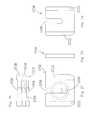
- FIG. 20is a top view of another dumbbell constructed according to the principles of the present invention.
- FIG. 21is a side view of the dumbbell of FIG. 20;
- FIG. 22is a side view of a weight selector on the dumbbell of FIGS. 20-21;
- FIG. 23is an end view of the weight selector of FIG. 22;
- FIG. 24is a side view of the weight selector of FIG. 22 rotated to a weight engaging orientation
- FIG. 25is an end view of the weight selector of FIG. 24;
- FIG. 26is a top view of weights plates suitable for use with the dumbbell of FIGS. 20-21;
- FIG. 27is an end view of one of the weight plates of FIG. 26;
- FIG. 28is a side view of the weight plate of FIG. 27;
- FIG. 29is an opposite end view of the weight plate of FIG. 27;
- FIG. 30is a top view of a dumbbell similar to the dumbbell of FIGS. 20-21, with optional features added;
- FIG. 31is a top view of a dumbbell similar to the dumbbell of FIGS. 20-21, with respective opposite side weight selectors connected to one another;
- FIG. 32is a side view of the dumbbell of FIG. 31
- the present inventionprovides methods and apparatus for selectively adjusting weight resistance to exercise motion.
- one or more weight selecting membersare rotated into and out of engagement with weight plates in order to select a desired number and/or combination of the weight plates.
- a first embodiment of the present inventionis an exercise dumbbell designated as 500 in FIG. 1 .
- the dumbbell 500has an intermediate handle 510 that is sized and configured for grasping, and opposite end, weight housings 520 that are sized and configured to accommodate respective weight plates 530 , 540 , and 550 .
- the supports 520 and the weight plates 530 , 540 , and 550rest on a base or cradle designated as 600 in FIGS. 17-19.
- Other suitable weight supporting arrangementsare disclosed in U.S. Pat. No. 4,284,463 to Shields; U.S. Pat. No. 4,529,198 to Hettick, Jr.; U.S. Pat. No. 4,822,034 to Shields; U.S. Pat. No.
- the handle 510is a cylindrical tube having a longitudinal axis and opposite ends secured to respective housings 520 by welding or other suitable means.
- Each of the housings 520includes an inside end wall 522 , an outside end wall 526 , a top wall 528 , and opposite side walls 529 , which cooperate to define a downwardly opening compartment.
- FIG. 1shows integrally molded housings 520
- FIG. 2shows an alternative housing 520 ′ that is identical in size and configuration, but assembled from three discrete parts. In either case, spacers may extend downward from the top wall 528 to occupy axial spaces between the weight plates 530 , 540 , and 550 .
- Axially offset shoulders 524are provided on interior, diametrically opposed sides of each end wall 522 and 526 to engage respective weights 530 and 550 and provide centrally located gaps therebetween.
- the shoulders 524are disposed inward from the outside edges of the walls 522 and 526 .
- a selector rod 560is rotatably mounted relative to both the handle 510 and the housings 520 .
- the selector rod 560includes a shaft 561 and two sets of three weight engaging members or supports 570 , 580 , and 590 mounted on opposite ends of the shaft 561 .
- the shaft 561includes an intermediate portion 562 having a circular profile, and opposite end portions 563 having clipped circular profiles (a flat surface is cut into an otherwise circular profile).
- the intermediate portion 562extends through the handle 510 and through the inside end wall 522 of each housing 520 .
- Each end portion 563extends through a respective housing 520 and through a respective outside end wall 526 .
- the innermost weight support 570is shown by itself in FIGS. 7-8.
- the support 570includes an axially extending hub 578 , a radially extending rim 576 , and an axially extending lip 573 .
- the support 570is a single piece of integrally molded plastic, and the rim 576 may be said to be integrally connected between the lip 573 and the hub 578 .
- An opening 579sized and configured to receive an end 563 of the shaft 561 , extends through the hub 578 and the rim 576 .
- the lip 573includes a single, continuous segment which extends through an arc of 167.5° The single segment spans several sectors, including sector Z, but it does not span any portion of sector A.
- the intermediate weight support 580is shown by itself in FIGS. 9-10.
- the support 580includes an axially extending hub 588 , a radially extending rim 586 , and an axially extending lip 584 .
- the support 580is a single piece of integrally molded plastic, and the rim 586 may be said to be integrally connected between the lip 583 and the hub 588 .
- An opening 589sized and configured to receive an end 563 of the shaft 561 , extends through the hub 588 and the rim 586 .
- the lip 583includes two diametrically opposed segments which extend through respective arcs of 77.5° One of the segments spans the sector Z, as well as another adjacent sector, but neither of the segments spans any portion of the sector A.
- the outermost weight support 590is shown by itself in FIGS. 11-12.
- the support 590includes an axially extending hub 598 , a radially extending rim 596 , and an axially extending lip 594 .
- the support 590is a single piece of integrally molded plastic, and the rim 596 may be said to be integrally connected between the lip 593 and the hub 598 .
- An opening 599sized and configured to receive an end 563 of the shaft 561 , extends through the hub 598 and the rim 596 .
- the lip 593includes four circumferentially spaced segments which extend through respective arcs of 32.5° One of the segments spans the sector Z, but none of the segments spans any portion of the sector A.
- a fasteneris fastened to one end 563 of the shaft 561 , just beyond the outside end wall 526 , and a knob 565 is fastened to an opposite end 563 of the shaft 561 just beyond the opposite, outside end wall 526 .
- the knob 565includes a relatively large diameter rim 566 which is sized and configured for grasping, an intermediate portion 567 which bears against the outside end wall 526 , and a relatively small diameter hub 568 which extends through the outside end wall 526 .
- a recess 506is provided in the hub 568 to receive a discrete fastener in countersunk fashion.
- the weight plates 530 , 540 , and 550are shown in greater detail in FIGS. 13-16.
- the two plates 540 and 550are shown with the same thickness, but the plate 550 is one-half as dense and thus, weighs one-half as much as the plate 540 , which in turn, weighs one-half as much as the plate 530 .
- the front and back views of the plate 550 shown in FIGS. 14 and 16are representative of similar views of the other plates 540 and 530 .
- Each side of the plate 550(and the plates 540 and 530 ) may be described with reference to a relatively thinner, intermediate portion 551 and relatively thicker, opposite side portions 552 .
- the side portions 552bear against adjacent counterparts and/or against shoulders 524 on respective end walls 522 or 526 , and the intermediate portion 551 cooperates with adjacent counterparts and/or the end walls 522 or 526 to define gaps 545 disposed between the side portions 552 and the shoulders 524 .
- the gaps 545are sized and configured to receive respective weight supports 570 , 580 , and 590 .
- FIG. 14shows how the plates 550 , 540 , and 530 axially align with the supports 590 , 580 , and 570 (the rim sectors A-Z are shown in dashed lines).
- An elongate slot 556sized and configured to accommodate the axial hub 598 , 588 , or 578 of a respective support 590 , 580 , or 570 extends downward into each of the plates 550 , 540 , and 530 .
- a peg 559projects axially outward from the intermediate portion 551 of the plate 550 (and each of the plates 540 and 530 ).
- the peg 559is disposed just inside the space (sectors A-Z) occupied by the axially extending lip 595 on the support 590 .
- the upper ends of the side portions 552terminate in respective laterally extending portions 553 that extend away from one another.
- the lateral portions 553are the same thickness as the side portions 552 .
- the lower ends 554 of the side portions 552are beveled or tapered.
- Relatively thinner, triangular fins 555extend between respective lateral portions 553 and respective side portions 552 .
- the fins 555are sized and configured to fit within opposing slots 625 in the base 600
- the lateral portions 553are designed to rest on top of the ledge 603 .
- Similar fins 555 on the plates 540 and 530are sized and configured to fit within other, respective slots 624 and 623 in the base 600 .
- the grooves 623 - 625are bounded by inclined, opposing walls which cooperate to center the plates 530 , 540 , and 550 relative to the base 600 .
- Additional grooves 622 and 626are provided in the base 600 to receive the end walls 522 and 526 , respectively.
- the grooves 626are bounded by relatively outward walls which are inclined upward and away from the middle of the base 600 .
- the base 600includes a bottom 610 sized and configured to rest upon a flat surface, such as a table top or floor. Opposite end portions 601 and 602 extend upward from the bottom 610 . In addition to outside walls, interior walls 604 extend upward from the bottom 610 and between opposing end walls 522 on respective housings 520 . Elongate slots 606 extend downward into the interior walls 604 to accommodate the handle 510 . When the plates 530 , 540 , and 550 are suspended from the base 600 , the slots 606 align with the slots 556 .
- the supports 570 , 580 , and 590are designed for rotation in 45° increments.
- a ball detent or other known biasing systemmay be interconnected between the housing 520 and either the knob 565 or the shaft selector rod 560 , for example, to bias the selector rod 560 toward the desired orientations.
- the lips 573 , 584 , and 595are configured to provide clearance or tolerance vis-a-vis the pegs 559 . In particular, when any given plate 530 , 540 , or 550 is not engaged, the respective lip 573 , 584 , or 595 is at least 6.5° outside the boundary of the peg 559 . With reference to the support 590 , for example, each of the lip segments 595 spans an arc of 32.5°.
- the weight selecting members 570 , 580 , and 590may also be configured to minimize wobbling or rattling of the selected weight plates.
- leaf springsmay be incorporated into the members 570 , 580 , and 590 during the molding process, for purposes of exerting pressure against any selected weights.
- the weightsmay also be configured to be relatively thicker just beneath the peg 559 , so that the leaf springs are relatively more compressed when disposed beneath the peg 559 .
- the configurations of the plates 530 , 540 , and 550 and the weight supports 570 , 580 , and 590are such that any combination of the plates 530 , 540 , and 550 may be secured to the handle 510 form removal from the base 600 .
- the supports 570 , 580 , and 590occupy the respective orientations shown in FIGS. 8, 10 , and 12
- the plate 530is engaged to the exclusion of the plates 540 and 550 .
- the supports 570 , 580 , and 590are rotated 180°, the sector designated as A underlies the pegs 559 on the plates 530 , 540 , and 550 , and none is secured to the handle 510 .
- the supports 570 , 580 , and 590are rotated until the sector designated as Z underlies the pegs 559 , all of the plates 530 , 540 , and 550 are engaged.
- the following chartshows how different amounts of weight may be selected as a function of the orientation of the selector rod 560 .
- An advantage of this embodiment 500is that only three discrete weights are required on each side of the dumbbell to provide eight different, balanced dumbbell loads. Moreover, the number of available dumbbell loads may be doubled by adding two “half-weights” which weigh one-half as much as one of the plates 590 . For example, half-weights could be connected to the inside end walls 522 of the base 510 by means of hook and loop fasteners.
- dumbbell 500Another advantage of the dumbbell 500 is that it can be manufactured relatively efficiently, especially as compared to the dumbbell disclosed in U.S. Pat. No. 5,839,997 to Roth et al.
- the relatively gross, “over/under” relationship between the weight supports 570 , 580 , and 590 and the weight plates 530 , 540 , and 550requires a less stringent manufacturing process.
- the weight supports 570 , 580 , and 590are relatively simple parts which may be injection molded, and the weights 530 , 540 , and 550 are relatively simple parts which may be cast.
- FIGS. 20-29show another dumbbell constructed according to the principles of the present invention.
- the dumbbell 1500has weight selectors 1570 , 1580 , and 1590 which rotate relative to a handle 1520 and independent of one another to provide eight different, balanced weight combinations (and sixteen combinations if balance is not a critical concern).
- First and second weight supporting boxes 1512are rigidly secured to respective end portions of the handle 1520 to collectively define a base 1510 .
- the weight selectors 1570 , 1580 , and 1590are disposed inside the boxes 1512 and are rotatably mounted on respective end portions of the handle 1520 .
- spacers 1525are also mounted on the handle 1520 to accommodate the additional thickness of the largest weight plates 1550 .
- the boxes 1512define weight receiving compartments 1514 , and the weight selectors 1570 , 1580 , and 1590 divide the compartments 1514 into individual weight receiving slots.
- FIGS. 22-23show the weight selector 1590 in a disengaged orientation
- FIGS. 24-25show the weight selector 1590 in a weight engaging orientation
- the weight selector 1590includes a cylindrical hub 1598 with a circular hole 1599 extending through same.
- a circular plate 1596extends radially away from the hub 1598
- a cylindrical rim 1595extends circumferentially about the majority of the plate 1596 .
- the gap in the rim 1595is disposed vertically beneath the hub 1598 when the weight selector 1590 occupies the disengaged orientation shown in FIGS. 22-23.
- An arm 1591extends radially away from the rim 1595 and terminates in an axially extending handle 1592 .
- FIGS. 26-29show weight plates 1530 , 1540 , and 1550 suitable for use with the dumbbell 1500 .
- Each plate 1530weighs ten pounds; each plate 1540 weighs five pounds; and each plate 1550 weighs two and one-half pounds.
- the platesmay be described as generally square plates having chamfered lower corners and relatively thick side walls 1552 .
- the walls 1552 on adjacent platescooperate to define central gaps ( 1548 , for example) between the plates to accommodate respective, intervening weight selectors.
- An elongate slot 1556extends downward from an upper edge of each plate to accommodate the hub 1598 of a respective weight selector.
- a boss 1559projects outward from the plate immediately beneath the lower end of the slot 1556 for selectively engagement by the rim 1595 on a respective weight selector (see dashed lines).
- the weight platesare stored on a suitable cradle when not in use.
- the arm 1591 on each of the weight selectors 1570 , 1580 , and 1590extends through a respective slot ( 1517 , for example) in the base 1510 , thereby making each handle 1592 accessible to a user.
- the ends ( 1507 , for example) of the slotsare notched to discourage undesired rotation of the handles 1592 .
- the handles 1592must be forced toward the center of the dumbbell 1500 prior to pivoting relative to the handle 1520 .
- the resilient nature of the arms 1591accommodate this level of deflection, in a manner similar to a leaf spring.
- FIG. 30shows a dumbbell 1500 ′ similar to the dumbbell 1500 , but with three additional features.
- indicia 1527 , 1528 , and 1529 on the tops of the boxes 1512 ′show the appropriate positions for the handles of respective weight selectors 1570 , 1580 , and 1590 for any desired amount of weight to be selected. For example, if twenty-five pounds is desired, then the handle 1592 on the weight selector 1590 is rotated toward the right side of FIG. 30, and the handles 1592 on the weight selectors 1580 and 1590 are rotated toward the left side of FIG. 30 .
- indicia 1521 , 1522 , and 1523are provided on the handle 1520 ′ to show appropriate center positions for the amount of weight that is selected. For example, if equal weight is selected on each end of the handle 1520 ′, then a person should center his hand relative to the line 1521 . On the other hand, if twenty-seven and one-half pounds is selected by rotating only the handle 1592 on the lower weight selector 1590 toward the right side of FIG. 30, then a person should center his hand relative to the line 1523 .
- One or both forms of similar indiciamay be provided on other embodiments discussed herein, as appropriate.
- the tops of the boxes 1512 ′ on the dumbbell 1500 ′are provided with relatively larger openings 1502 at the ends of the slots nearer the right side of FIG. 30 .
- the openings 1502are sized and configured to admit passage of the handles 1592 during assembly of the dumbbell 1500 ′. Similar openings 1502 may be provided on the dumbbell 1500 , or the weight selectors 1570 , 1580 , and 1590 may be assembled from more than one piece to facilitate insertion of the arms 1591 through the slots, or the handles 1592 may be made no larger than the openings 1507 shown in FIG. 20 .
- FIGS. 31-32show a dumbbell 1600 similar to the dumbbell 1500 , but with interconnected pairs of weight selectors designated as 1670 , 1680 , and 1690 , and a base 1610 that has been modified to accommodate same.
- the base 1610includes the same handle 1520 and similarly sized boxes 1612 rigidly secured to opposite ends of the handle 1520 .
- the boxes 1612define weight receiving compartments 1514 which are separated into individual weight slots by weight selectors rotatably mounted on the handle 1520 .
- the top of each box 1612is provided with an upwardly extending rim 1613 that extends along the outside end and the opposing sides to shelter the weight selectors and structure for latching same in place.
- the weight selector 1670may be described in terms of opposite side weight selectors 1570 having their handles 1592 interconnected by an integral extension 1673 .
- the weight selector 1680may be described in terms of opposite side weight selectors 1580 having relatively longer arms and their handles 1592 interconnected by a relatively longer integral extension 1683 .
- the weight selector 1690may be described in terms of opposite side weight selectors 1590 having even longer arms and their handles 1592 interconnected by an even longer integral extension 1693 .
- Relatively longer slots( 1619 , for example) are provided in the tops of the boxes 1612 to accommodate pivoting of the longer arms. For assembly purposes, the arms may be inserted through respective slots and then interconnected by respective extensions 1673 , 1683 , and 1693 .
- Inverted L-shaped tabs 1609are provided on the boxes 1612 proximate the ends of the slots to latch respective weight selector pairs 1670 , 1680 , and 1690 in place.
- the tabs 1609 and/or the armsresiliently deflect to accommodate the latching and unlatching process.
- An advantage of this embodiment 1600is that the opposite side weight plates are latched and unlatched simultaneously.
- the present inventionmay also be described in various ways.
- the present inventionmay be described as an adjustable exercise weight system, comprising: a base which includes a handle and weight supports at opposite ends of the handle; weights sized and configured for engagement by the weight supports; and weight selectors rotatably mounted on the handle and disposed adjacent respective weights, wherein each of the weight selectors is independently rotatable between a weight engaging orientation and a free orientation relative to a respective one of the weights.
- the weightsmay be provided in opposite side pairs, and/or the opposite side weight selectors associated with each of the pairs may be interconnected to move as a unit.
- indiciamay be provided to show how the weight selectors should be maneuvered to select a desired amount of weight, and/or to indicate where the handle should be grasped in order to offset an imbalance in the amount of selected weight at each end of the handle.
- the present inventionmay also be described in terms of various methods of providing adjustable weight resistance.
- one such methodinvolves the provision of a plurality of aligned weights; the provision of a discrete weight support for each of the weights; and the rotation of the supports relative to the weights until a respective weight support underlies each desired weight.
- This methodmay further involve mounting the weight supports on a rod, and providing slots in the weights to receive the rod; having the rod occupy all such slots during rotation, regardless of which weights are being selected; rotating the rod a fraction of a revolution to engage an additional weight; and/or exerting pressure against the selected weights.
- a weight stabilizing systemmay be implemented by providing protruding portion(s) on the weight plates and/or the weight selectors, and arranging the protruding portions to engage only when the weight selectors are rotated into engagement with respective weights.
- a leaf spring on the weight selectormay be arranged to occupy the slot in the weight when not engaged, and to rest between spaced apart bumps on the weight when the weight selector is moved to an engagement orientation.
- the present inventionmay also be described as a method of adjusting exercise resistance, involving provision of a plurality of aligned weights; provision of a discrete weight support for each of the weights; and rotation of the weight supports into engagement with desired weights.
- the weight supportsmay be independently rotated or secured to a common selector rod.
- the selector rodmay be rotated a first amount relative to the weights to engage a first weight; and rotated a second amount relative to the weights to engage a second weight.
- Such a methodmay further involve rotating the selector rod a first amount to engage only the first weight, a second amount to engage only the second weight, and a third amount to engage both the first weight and the second weight.
Landscapes
- Health & Medical Sciences (AREA)
- Life Sciences & Earth Sciences (AREA)
- Biophysics (AREA)
- Orthopedic Medicine & Surgery (AREA)
- General Health & Medical Sciences (AREA)
- Physical Education & Sports Medicine (AREA)
- Rehabilitation Tools (AREA)
Abstract
Description
| Handle | Weights | 590 | Total | |||
| — | 10 | 0 | 0 | 0 | 10 | |
| 45° | 10 | 5 | 0 | 0 | 5 | |
| 90° | 10 | 0 | 10 | 0 | 20 | |
| 135° | 10 | 5 | 10 | 0 | 25 | |
| 180° | 10 | 0 | 0 | 20 | 30 | |
| 225° | 10 | 5 | 0 | 10 | 35 | |
| 270° | 10 | 0 | 10 | 20 | 40 | |
| 35° | 10 | 5 | 10 | 20 | 45 | |
| 360° | 10 | 0 | 0 | 0 | 10 | |
Claims (18)
Priority Applications (3)
| Application Number | Priority Date | Filing Date | Title |
|---|---|---|---|
| US09/745,822US6669606B2 (en) | 1998-11-17 | 2000-12-21 | Weight selection methods and apparatus |
| US09/796,233US6749547B2 (en) | 1999-12-21 | 2001-02-28 | Weight selection methods and apparatus |
| US10/867,834US7153243B1 (en) | 1999-12-21 | 2004-06-15 | Weight selection methods |
Applications Claiming Priority (5)
| Application Number | Priority Date | Filing Date | Title |
|---|---|---|---|
| US10876898P | 1998-11-17 | 1998-11-17 | |
| US11901499P | 1999-02-08 | 1999-02-08 | |
| US09/300,546US6422979B1 (en) | 1996-07-19 | 1999-04-27 | Weight selection methods for adjusting resistance to exercise |
| US17181399P | 1999-12-21 | 1999-12-21 | |
| US09/745,822US6669606B2 (en) | 1998-11-17 | 2000-12-21 | Weight selection methods and apparatus |
Related Parent Applications (1)
| Application Number | Title | Priority Date | Filing Date |
|---|---|---|---|
| US09/300,546Continuation-In-PartUS6422979B1 (en) | 1996-07-19 | 1999-04-27 | Weight selection methods for adjusting resistance to exercise |
Related Child Applications (1)
| Application Number | Title | Priority Date | Filing Date |
|---|---|---|---|
| US09/796,233Continuation-In-PartUS6749547B2 (en) | 1999-12-21 | 2001-02-28 | Weight selection methods and apparatus |
Publications (2)
| Publication Number | Publication Date |
|---|---|
| US20010003723A1 US20010003723A1 (en) | 2001-06-14 |
| US6669606B2true US6669606B2 (en) | 2003-12-30 |
Family
ID=27493653
Family Applications (1)
| Application Number | Title | Priority Date | Filing Date |
|---|---|---|---|
| US09/745,822Expired - Fee RelatedUS6669606B2 (en) | 1998-11-17 | 2000-12-21 | Weight selection methods and apparatus |
Country Status (1)
| Country | Link |
|---|---|
| US (1) | US6669606B2 (en) |
Cited By (82)
| Publication number | Priority date | Publication date | Assignee | Title |
|---|---|---|---|---|
| US20040005969A1 (en)* | 2001-05-31 | 2004-01-08 | Paul Chen | Adjustable dumbbell |
| US20040220025A1 (en)* | 1997-09-29 | 2004-11-04 | Krull Mark A. | Exercise resistance methods and apparatus |
| US20050079961A1 (en)* | 2003-10-13 | 2005-04-14 | Dalebout William T. | Weight lifting system with internal cam mechanism |
| USD508628S1 (en) | 2002-07-31 | 2005-08-23 | Nautilus, Inc. | Adjustable dumbbell support base |
| US7060011B1 (en)* | 1997-09-29 | 2006-06-13 | Krull Mark A | Exercise resistance methods and apparatus |
| US7070545B2 (en) | 2002-07-01 | 2006-07-04 | Nautilus, Inc. | Leg press and abdominal crunch exercise machine |
| US7077790B1 (en) | 2002-01-31 | 2006-07-18 | Krull Mark A | Adjustable weight exercise methods and apparatus |
| US7077791B2 (en) | 2002-04-18 | 2006-07-18 | Mautilus, Inc. | Weight selection methods and apparatus |
| US7083554B1 (en) | 1997-02-27 | 2006-08-01 | Nautilus, Inc. | Exercise machine with infinite position range limiter and automatic belt tensioning system |
| US7087000B1 (en) | 2003-10-27 | 2006-08-08 | Morris Wayne Walker | Collarless barbell sleeve |
| US20060189458A1 (en)* | 2005-01-27 | 2006-08-24 | D.K.B. Group, Llc | Weight-training apparatus having selectable weight plates |
| USD528173S1 (en) | 2003-06-05 | 2006-09-12 | Nautilus, Inc. | Adjustable dumbbell base |
| US20060205571A1 (en)* | 2004-12-14 | 2006-09-14 | Krull Mark A | Exercise weight stack methods and apparatus |
| USD528611S1 (en) | 2004-08-16 | 2006-09-19 | Nautilus, Inc. | Adjustable dumbbell |
| US7108641B2 (en) | 2000-05-03 | 2006-09-19 | Nautilus, Inc. | Exercise equipment with multi-positioning handles |
| US20060217245A1 (en)* | 2005-03-17 | 2006-09-28 | Nautilus, Inc. | Weight selection apparatus for a weight stack |
| US7115080B2 (en) | 2002-08-01 | 2006-10-03 | Nautilus, Inc. | Collapsible seat for combination hack squat and leg press machine |
| US7153243B1 (en)* | 1999-12-21 | 2006-12-26 | Krull Mark A | Weight selection methods |
| USD540405S1 (en) | 2002-07-31 | 2007-04-10 | Nautilus, Inc. | Adjustable dumbbell |
| USD540894S1 (en) | 2002-08-01 | 2007-04-17 | Nautilus, Inc. | Adjustable dumbbell |
| US7261678B2 (en) | 2002-06-07 | 2007-08-28 | Nautilus, Inc. | Adjustable dumbbell system |
| US7264578B1 (en)* | 1997-09-29 | 2007-09-04 | Krull Mark A | Exercise resistance method using an adjustable weight dumbbell |
| USD584086S1 (en) | 2008-01-23 | 2009-01-06 | Nautilus, Inc. | Dumbbell base |
| US20090023561A1 (en)* | 2007-07-20 | 2009-01-22 | Exersmart, Llc | Resistance system for fitness equipment |
| US20090149301A1 (en)* | 2007-12-07 | 2009-06-11 | Johnson Health Tech Co., Ltd. | Resistance exercise apparatus |
| US20090163333A1 (en)* | 2007-12-20 | 2009-06-25 | Precor Incorporated | Weight stack selector |
| US20090163334A1 (en)* | 2007-12-20 | 2009-06-25 | Precor Incorporated | Incremental weight and selector |
| US20090163332A1 (en)* | 2007-12-20 | 2009-06-25 | Precor Incorporated | Weight stack selector |
| USD603002S1 (en) | 2008-12-08 | 2009-10-27 | Nautilus, Inc. | Dumbbell support structure |
| USD603469S1 (en) | 2008-01-23 | 2009-11-03 | Nautilus, Inc. | Dumbbell weight plate |
| USD603915S1 (en) | 2008-01-23 | 2009-11-10 | Nautilus, Inc, | Dumbbell weight plate |
| US7625322B1 (en) | 2007-09-19 | 2009-12-01 | Krull Mark A | Exercise weight adjustment methods and apparatus |
| US7662074B2 (en) | 2004-10-04 | 2010-02-16 | Nautilus, Inc. | Exercise machine having rotatable weight selection index |
| USD610636S1 (en) | 2008-01-23 | 2010-02-23 | Nautilus, Inc. | Dumbbell |
| USD617854S1 (en) | 2008-12-08 | 2010-06-15 | Nautilus, Inc. | Dumbbell weight plate |
| US7736283B2 (en) | 2006-10-04 | 2010-06-15 | Nautilus, Inc. | Exercise machine having rotatable weight selection index |
| US20110045956A1 (en)* | 2009-07-31 | 2011-02-24 | Matthew Colledge | Weightlifting device with mechanism for disengaging weight plates |
| US7922635B2 (en) | 2000-03-10 | 2011-04-12 | Nautilus, Inc. | Adjustable-load unitary multi-position bench exercise unit |
| US20110092345A1 (en)* | 2009-10-21 | 2011-04-21 | Personality Gym Ab | Dumbbell |
| US8025613B1 (en) | 2010-09-24 | 2011-09-27 | Beto Engineering & Marketing Co., Ltd. | Adjustable dumbbell |
| US20110263393A1 (en)* | 2010-04-22 | 2011-10-27 | Exemplar Design, Llc | Adjustable exercise devices |
| US8137248B1 (en)* | 1997-09-29 | 2012-03-20 | Krull Mark A | Exercise resistance apparatus |
| US8568279B2 (en) | 2010-03-31 | 2013-10-29 | Nautilus, Inc. | Engagement interface for an exercise machine |
| US8771153B2 (en) | 2010-11-08 | 2014-07-08 | Icon Ip, Inc. | Exercise weight bar with rotating handle and cam selection device |
| US8790223B2 (en) | 2012-06-28 | 2014-07-29 | Beto Engineering & Marketing Co., Ltd. | Adjustable dumbbell |
| US8845498B2 (en) | 2010-03-31 | 2014-09-30 | Nautilus, Inc. | Lockout mechanism for a weight stack exercise machine |
| US8876674B2 (en) | 2010-03-31 | 2014-11-04 | Nautilus, Inc. | Selectable weight stack |
| US8992396B2 (en) | 2012-07-27 | 2015-03-31 | Beto Engineering & Marketing Co., Ltd. | Adjustable dumbbell |
| USD737907S1 (en) | 2014-06-13 | 2015-09-01 | Nautilus, Inc. | Dumbbell |
| US9186537B2 (en) | 2013-01-03 | 2015-11-17 | Precor Incorporated | Incremental weight and selector |
| USD743713S1 (en) | 2014-06-13 | 2015-11-24 | Nautilus, Inc. | Dumbbell base |
| USD745939S1 (en) | 2013-03-15 | 2015-12-22 | Arqex Outdoor Fitness Systems, Llc | Strength training and stretching machine with adjustable arms |
| USD753247S1 (en) | 2014-06-13 | 2016-04-05 | Nautilus, Inc. | Dumbbell bridge |
| USD753246S1 (en) | 2013-03-15 | 2016-04-05 | Arqex Outdoor Fitness Systems, Llc | Strength training and stretching machine |
| US9314658B2 (en) | 2013-03-15 | 2016-04-19 | Arqex Outdoor Fitness Systems, Llc | Strength training and stretching system |
| US9375602B2 (en) | 2013-03-15 | 2016-06-28 | Nautilus, Inc. | Exercise dumbbells |
| US9555280B2 (en) | 2013-03-15 | 2017-01-31 | Arqex Outdoor Fitness Systems, Llc | Attachment assembly for an exercise device and an exercise device incorporating the same |
| US9555278B2 (en) | 2013-03-15 | 2017-01-31 | Arqfx Outdoor Fitness Systems, Llc | Strength training and stretching system and resistance band assembly for use therewith |
| USD777850S1 (en) | 2015-01-16 | 2017-01-31 | Arqex Outdoor Fitness Systems, Llc | Variable resistance band |
| US9630048B2 (en) | 2013-03-15 | 2017-04-25 | Arqex Outdoor Fitness Systems, Llc | Variable resistance band assembly and method of using the same |
| US9682267B2 (en) | 2013-03-15 | 2017-06-20 | Arqex Outdoor Fitness Systems, Llc | Insert for use with a resistance band assembly and a method of using the same |
| US9724553B2 (en) | 2013-03-15 | 2017-08-08 | Arqex Outdoor Fitness Systems, Llc | Resistance band assembly and a method of varying a resistive force applied thereby |
| US9776032B2 (en) | 2014-06-20 | 2017-10-03 | Nautilus, Inc. | Adjustable dumbbell system having a weight sensor |
| US9814922B2 (en) | 2014-12-31 | 2017-11-14 | Nautilus, Inc. | Weight sensing base for an adjustable dumbbell system |
| US9895571B2 (en) | 2016-02-22 | 2018-02-20 | Beto Engineering & Marketing Co., Ltd. | Adjustable exercise device |
| US9956451B1 (en) | 2016-11-03 | 2018-05-01 | Beto Engineering & Marketing Co., Ltd. | Adjustable exercise device |
| US10022583B2 (en) | 2016-03-04 | 2018-07-17 | Beto Engineering & Marketing Co., Ltd. | Base support for dumbbell assembly |
| US10188890B2 (en) | 2013-12-26 | 2019-01-29 | Icon Health & Fitness, Inc. | Magnetic resistance mechanism in a cable machine |
| US10195477B2 (en) | 2014-06-20 | 2019-02-05 | Nautilus, Inc. | Adjustable dumbbell system having a weight sensor |
| US10252109B2 (en) | 2016-05-13 | 2019-04-09 | Icon Health & Fitness, Inc. | Weight platform treadmill |
| US10279212B2 (en) | 2013-03-14 | 2019-05-07 | Icon Health & Fitness, Inc. | Strength training apparatus with flywheel and related methods |
| US10293211B2 (en) | 2016-03-18 | 2019-05-21 | Icon Health & Fitness, Inc. | Coordinated weight selection |
| US10328299B2 (en) | 2017-06-09 | 2019-06-25 | Beto Engineering & Marketing Co., Ltd. | Adjustable exercise device |
| US10426989B2 (en) | 2014-06-09 | 2019-10-01 | Icon Health & Fitness, Inc. | Cable system incorporated into a treadmill |
| US10441840B2 (en) | 2016-03-18 | 2019-10-15 | Icon Health & Fitness, Inc. | Collapsible strength exercise machine |
| US10449416B2 (en) | 2015-08-26 | 2019-10-22 | Icon Health & Fitness, Inc. | Strength exercise mechanisms |
| US10463906B2 (en) | 2018-02-02 | 2019-11-05 | Jaxamo Ltd. | Exercise devices, systems, and methods |
| US10518123B2 (en) | 2014-06-13 | 2019-12-31 | Nautilus, Inc. | Adjustable dumbbell system |
| US10661114B2 (en) | 2016-11-01 | 2020-05-26 | Icon Health & Fitness, Inc. | Body weight lift mechanism on treadmill |
| US10940360B2 (en) | 2015-08-26 | 2021-03-09 | Icon Health & Fitness, Inc. | Strength exercise mechanisms |
| US11857827B2 (en) | 2021-11-19 | 2024-01-02 | Nautilus, Inc. | Plate-sensing base for a connected adjustable free weight system |
| USD1022081S1 (en) | 2023-05-22 | 2024-04-09 | Dane Hoover | Exercise bench |
Families Citing this family (4)
| Publication number | Priority date | Publication date | Assignee | Title |
|---|---|---|---|---|
| US7771330B2 (en)* | 2006-08-02 | 2010-08-10 | Power Block Holdings, Inc. | Selectorized dumbbell having shock absorbing system |
| US10010742B2 (en) | 2016-01-26 | 2018-07-03 | Powerblock Holdings, Inc. | Selectorized dumbbell with a weight selector having a continuous periphery that encloses an open interior |
| CN111821649A (en)* | 2020-07-30 | 2020-10-27 | 广州成呈智能科技有限公司 | Automatic balancing weight changing and cleaning protection device during barbell lifting |
| CN112023361B (en)* | 2020-09-17 | 2024-11-22 | 济南朗威健康科技有限公司 | Wrist Strength Trainer |
Citations (6)
| Publication number | Priority date | Publication date | Assignee | Title |
|---|---|---|---|---|
| US3647209A (en)* | 1970-05-15 | 1972-03-07 | Jack La Lanne | Weight lifting type exercising device |
| SU1258447A1 (en)* | 1985-03-26 | 1986-09-23 | Белорусский Ордена Трудового Красного Знамени Политехнический Институт | Apparatus for developing the leg muscle force |
| US5839997A (en)* | 1998-01-22 | 1998-11-24 | Premise Group Llc | Weight-lifting apparatus and method |
| US6261022B1 (en)* | 1998-03-17 | 2001-07-17 | Icon Health & Fitness, Inc. | Adjustable dumbbell and system |
| US6402666B2 (en)* | 1999-04-13 | 2002-06-11 | Mark A. Krull | Adjustable weight exercise methods and apparatus |
| US6422979B1 (en)* | 1996-07-19 | 2002-07-23 | Mark A. Krull | Weight selection methods for adjusting resistance to exercise |
- 2000
- 2000-12-21USUS09/745,822patent/US6669606B2/ennot_activeExpired - Fee Related
Patent Citations (6)
| Publication number | Priority date | Publication date | Assignee | Title |
|---|---|---|---|---|
| US3647209A (en)* | 1970-05-15 | 1972-03-07 | Jack La Lanne | Weight lifting type exercising device |
| SU1258447A1 (en)* | 1985-03-26 | 1986-09-23 | Белорусский Ордена Трудового Красного Знамени Политехнический Институт | Apparatus for developing the leg muscle force |
| US6422979B1 (en)* | 1996-07-19 | 2002-07-23 | Mark A. Krull | Weight selection methods for adjusting resistance to exercise |
| US5839997A (en)* | 1998-01-22 | 1998-11-24 | Premise Group Llc | Weight-lifting apparatus and method |
| US6261022B1 (en)* | 1998-03-17 | 2001-07-17 | Icon Health & Fitness, Inc. | Adjustable dumbbell and system |
| US6402666B2 (en)* | 1999-04-13 | 2002-06-11 | Mark A. Krull | Adjustable weight exercise methods and apparatus |
Cited By (113)
| Publication number | Priority date | Publication date | Assignee | Title |
|---|---|---|---|---|
| US7083554B1 (en) | 1997-02-27 | 2006-08-01 | Nautilus, Inc. | Exercise machine with infinite position range limiter and automatic belt tensioning system |
| US8137248B1 (en)* | 1997-09-29 | 2012-03-20 | Krull Mark A | Exercise resistance apparatus |
| US6974405B2 (en)* | 1997-09-29 | 2005-12-13 | Krull Mark A | Exercise resistance methods and apparatus |
| US7060011B1 (en)* | 1997-09-29 | 2006-06-13 | Krull Mark A | Exercise resistance methods and apparatus |
| US7264578B1 (en)* | 1997-09-29 | 2007-09-04 | Krull Mark A | Exercise resistance method using an adjustable weight dumbbell |
| US20040220025A1 (en)* | 1997-09-29 | 2004-11-04 | Krull Mark A. | Exercise resistance methods and apparatus |
| US7153243B1 (en)* | 1999-12-21 | 2006-12-26 | Krull Mark A | Weight selection methods |
| US7922635B2 (en) | 2000-03-10 | 2011-04-12 | Nautilus, Inc. | Adjustable-load unitary multi-position bench exercise unit |
| US7608028B2 (en) | 2000-05-03 | 2009-10-27 | Nautilus, Inc. | Exercise equipment with multi-positioning handles |
| US7108641B2 (en) | 2000-05-03 | 2006-09-19 | Nautilus, Inc. | Exercise equipment with multi-positioning handles |
| US20040005969A1 (en)* | 2001-05-31 | 2004-01-08 | Paul Chen | Adjustable dumbbell |
| US7223214B2 (en)* | 2001-05-31 | 2007-05-29 | Paul Chen | Adjustable dumbbell |
| US7077790B1 (en) | 2002-01-31 | 2006-07-18 | Krull Mark A | Adjustable weight exercise methods and apparatus |
| US7534199B2 (en)* | 2002-04-18 | 2009-05-19 | Nautilus, Inc. | Weight selection methods and apparatus |
| US7077791B2 (en) | 2002-04-18 | 2006-07-18 | Mautilus, Inc. | Weight selection methods and apparatus |
| US7614982B2 (en) | 2002-06-07 | 2009-11-10 | Nautilus, Inc. | Adjustable dumbbell system |
| US7261678B2 (en) | 2002-06-07 | 2007-08-28 | Nautilus, Inc. | Adjustable dumbbell system |
| US8002680B2 (en) | 2002-06-07 | 2011-08-23 | Nautilus, Inc. | Adjustable dumbbell system |
| US7794373B2 (en) | 2002-06-07 | 2010-09-14 | Nautilus, Inc. | Adjustable dumbbell system |
| US7553265B2 (en) | 2002-06-07 | 2009-06-30 | Nautilus, Inc. | Adjustable dumbbell system |
| US7070545B2 (en) | 2002-07-01 | 2006-07-04 | Nautilus, Inc. | Leg press and abdominal crunch exercise machine |
| US7608022B2 (en) | 2002-07-01 | 2009-10-27 | Nautilus, Inc. | Leg press and abdominal crunch exercise machine |
| USD540405S1 (en) | 2002-07-31 | 2007-04-10 | Nautilus, Inc. | Adjustable dumbbell |
| USD508628S1 (en) | 2002-07-31 | 2005-08-23 | Nautilus, Inc. | Adjustable dumbbell support base |
| USD540894S1 (en) | 2002-08-01 | 2007-04-17 | Nautilus, Inc. | Adjustable dumbbell |
| US7115080B2 (en) | 2002-08-01 | 2006-10-03 | Nautilus, Inc. | Collapsible seat for combination hack squat and leg press machine |
| USD528173S1 (en) | 2003-06-05 | 2006-09-12 | Nautilus, Inc. | Adjustable dumbbell base |
| US7025713B2 (en) | 2003-10-13 | 2006-04-11 | Icon Ip, Inc. | Weight lifting system with internal cam mechanism |
| US20050079961A1 (en)* | 2003-10-13 | 2005-04-14 | Dalebout William T. | Weight lifting system with internal cam mechanism |
| US7087000B1 (en) | 2003-10-27 | 2006-08-08 | Morris Wayne Walker | Collarless barbell sleeve |
| USD528611S1 (en) | 2004-08-16 | 2006-09-19 | Nautilus, Inc. | Adjustable dumbbell |
| US7662074B2 (en) | 2004-10-04 | 2010-02-16 | Nautilus, Inc. | Exercise machine having rotatable weight selection index |
| US8016729B2 (en) | 2004-10-04 | 2011-09-13 | Nautilus, Inc. | Exercise machine having rotatable weight selection index |
| US7740568B2 (en) | 2004-10-04 | 2010-06-22 | Nautilus, Inc. | Exercise machine having rotatable weight selection index |
| US7540832B2 (en) | 2004-12-14 | 2009-06-02 | Nautilus, Inc. | Exercise weight stack methods and apparatus |
| US7507189B2 (en) | 2004-12-14 | 2009-03-24 | Nautilus, Inc. | Exercise weight stack apparatus |
| US20060205571A1 (en)* | 2004-12-14 | 2006-09-14 | Krull Mark A | Exercise weight stack methods and apparatus |
| US7121988B2 (en) | 2005-01-27 | 2006-10-17 | D.K.B. Group, Llc | Weight-training apparatus having selectable weight plates |
| US20060189458A1 (en)* | 2005-01-27 | 2006-08-24 | D.K.B. Group, Llc | Weight-training apparatus having selectable weight plates |
| US7758478B2 (en) | 2005-03-17 | 2010-07-20 | Nautilus, Inc. | Weight selection apparatus for a weight stack |
| US20060217245A1 (en)* | 2005-03-17 | 2006-09-28 | Nautilus, Inc. | Weight selection apparatus for a weight stack |
| US7736283B2 (en) | 2006-10-04 | 2010-06-15 | Nautilus, Inc. | Exercise machine having rotatable weight selection index |
| US20090023561A1 (en)* | 2007-07-20 | 2009-01-22 | Exersmart, Llc | Resistance system for fitness equipment |
| US7887468B2 (en) | 2007-07-20 | 2011-02-15 | Exersmart, Llc | Resistance system for fitness equipment |
| US7625322B1 (en) | 2007-09-19 | 2009-12-01 | Krull Mark A | Exercise weight adjustment methods and apparatus |
| US20090149301A1 (en)* | 2007-12-07 | 2009-06-11 | Johnson Health Tech Co., Ltd. | Resistance exercise apparatus |
| US7850580B2 (en)* | 2007-12-07 | 2010-12-14 | Johnson Health Tech Co., Ltd. | Resistance exercise apparatus |
| US20090163333A1 (en)* | 2007-12-20 | 2009-06-25 | Precor Incorporated | Weight stack selector |
| US7708672B2 (en) | 2007-12-20 | 2010-05-04 | Precor Incorporated | Incremental weight and selector |
| US7871357B2 (en) | 2007-12-20 | 2011-01-18 | Precor Incorporated | Weight stack selector |
| US20090163332A1 (en)* | 2007-12-20 | 2009-06-25 | Precor Incorporated | Weight stack selector |
| US20090163334A1 (en)* | 2007-12-20 | 2009-06-25 | Precor Incorporated | Incremental weight and selector |
| US7815554B2 (en) | 2007-12-20 | 2010-10-19 | Precor Incorporated | Weight stack selector |
| USD610636S1 (en) | 2008-01-23 | 2010-02-23 | Nautilus, Inc. | Dumbbell |
| USD584086S1 (en) | 2008-01-23 | 2009-01-06 | Nautilus, Inc. | Dumbbell base |
| USD603915S1 (en) | 2008-01-23 | 2009-11-10 | Nautilus, Inc, | Dumbbell weight plate |
| USD603469S1 (en) | 2008-01-23 | 2009-11-03 | Nautilus, Inc. | Dumbbell weight plate |
| USD617854S1 (en) | 2008-12-08 | 2010-06-15 | Nautilus, Inc. | Dumbbell weight plate |
| USD603002S1 (en) | 2008-12-08 | 2009-10-27 | Nautilus, Inc. | Dumbbell support structure |
| US20110045956A1 (en)* | 2009-07-31 | 2011-02-24 | Matthew Colledge | Weightlifting device with mechanism for disengaging weight plates |
| US8298125B2 (en) | 2009-07-31 | 2012-10-30 | Icon Health & Fitness, Inc. | Weightlifting device with mechanism for disengaging weight plates |
| US20110092345A1 (en)* | 2009-10-21 | 2011-04-21 | Personality Gym Ab | Dumbbell |
| US8206274B2 (en)* | 2009-10-21 | 2012-06-26 | Personality Gym Ab | Dumbbell |
| US8845498B2 (en) | 2010-03-31 | 2014-09-30 | Nautilus, Inc. | Lockout mechanism for a weight stack exercise machine |
| US8568279B2 (en) | 2010-03-31 | 2013-10-29 | Nautilus, Inc. | Engagement interface for an exercise machine |
| US8876674B2 (en) | 2010-03-31 | 2014-11-04 | Nautilus, Inc. | Selectable weight stack |
| US20110263393A1 (en)* | 2010-04-22 | 2011-10-27 | Exemplar Design, Llc | Adjustable exercise devices |
| US8608627B2 (en)* | 2010-04-22 | 2013-12-17 | Exemplar Design, Llc | Adjustable exercise devices |
| US8025613B1 (en) | 2010-09-24 | 2011-09-27 | Beto Engineering & Marketing Co., Ltd. | Adjustable dumbbell |
| US8771153B2 (en) | 2010-11-08 | 2014-07-08 | Icon Ip, Inc. | Exercise weight bar with rotating handle and cam selection device |
| US8790223B2 (en) | 2012-06-28 | 2014-07-29 | Beto Engineering & Marketing Co., Ltd. | Adjustable dumbbell |
| US8992396B2 (en) | 2012-07-27 | 2015-03-31 | Beto Engineering & Marketing Co., Ltd. | Adjustable dumbbell |
| US9186537B2 (en) | 2013-01-03 | 2015-11-17 | Precor Incorporated | Incremental weight and selector |
| US10279212B2 (en) | 2013-03-14 | 2019-05-07 | Icon Health & Fitness, Inc. | Strength training apparatus with flywheel and related methods |
| USD753246S1 (en) | 2013-03-15 | 2016-04-05 | Arqex Outdoor Fitness Systems, Llc | Strength training and stretching machine |
| USD745939S1 (en) | 2013-03-15 | 2015-12-22 | Arqex Outdoor Fitness Systems, Llc | Strength training and stretching machine with adjustable arms |
| US11998789B2 (en) | 2013-03-15 | 2024-06-04 | Kayezen, Llc | Resistance band assembly |
| US9314658B2 (en) | 2013-03-15 | 2016-04-19 | Arqex Outdoor Fitness Systems, Llc | Strength training and stretching system |
| US9375602B2 (en) | 2013-03-15 | 2016-06-28 | Nautilus, Inc. | Exercise dumbbells |
| US9555280B2 (en) | 2013-03-15 | 2017-01-31 | Arqex Outdoor Fitness Systems, Llc | Attachment assembly for an exercise device and an exercise device incorporating the same |
| US9555278B2 (en) | 2013-03-15 | 2017-01-31 | Arqfx Outdoor Fitness Systems, Llc | Strength training and stretching system and resistance band assembly for use therewith |
| US9604092B2 (en) | 2013-03-15 | 2017-03-28 | Nautilus, Inc. | Exercise dumbbells |
| US9630048B2 (en) | 2013-03-15 | 2017-04-25 | Arqex Outdoor Fitness Systems, Llc | Variable resistance band assembly and method of using the same |
| US9682267B2 (en) | 2013-03-15 | 2017-06-20 | Arqex Outdoor Fitness Systems, Llc | Insert for use with a resistance band assembly and a method of using the same |
| US9724553B2 (en) | 2013-03-15 | 2017-08-08 | Arqex Outdoor Fitness Systems, Llc | Resistance band assembly and a method of varying a resistive force applied thereby |
| US10188890B2 (en) | 2013-12-26 | 2019-01-29 | Icon Health & Fitness, Inc. | Magnetic resistance mechanism in a cable machine |
| US10426989B2 (en) | 2014-06-09 | 2019-10-01 | Icon Health & Fitness, Inc. | Cable system incorporated into a treadmill |
| USD737907S1 (en) | 2014-06-13 | 2015-09-01 | Nautilus, Inc. | Dumbbell |
| US10518123B2 (en) | 2014-06-13 | 2019-12-31 | Nautilus, Inc. | Adjustable dumbbell system |
| US12070649B2 (en) | 2014-06-13 | 2024-08-27 | Johnson Health Tech Retail, Inc. | Adjustable dumbbell system |
| USD743713S1 (en) | 2014-06-13 | 2015-11-24 | Nautilus, Inc. | Dumbbell base |
| US11801415B2 (en) | 2014-06-13 | 2023-10-31 | Nautilus, Inc. | Adjustable dumbbell system |
| US11452902B2 (en) | 2014-06-13 | 2022-09-27 | Nautilus, Inc. | Adjustable dumbbell system |
| USD753247S1 (en) | 2014-06-13 | 2016-04-05 | Nautilus, Inc. | Dumbbell bridge |
| US9776032B2 (en) | 2014-06-20 | 2017-10-03 | Nautilus, Inc. | Adjustable dumbbell system having a weight sensor |
| US10195477B2 (en) | 2014-06-20 | 2019-02-05 | Nautilus, Inc. | Adjustable dumbbell system having a weight sensor |
| US10617905B2 (en) | 2014-06-20 | 2020-04-14 | Nautilus, Inc. | Adjustable dumbbell system having a weight sensor |
| US9814922B2 (en) | 2014-12-31 | 2017-11-14 | Nautilus, Inc. | Weight sensing base for an adjustable dumbbell system |
| USD777850S1 (en) | 2015-01-16 | 2017-01-31 | Arqex Outdoor Fitness Systems, Llc | Variable resistance band |
| US10940360B2 (en) | 2015-08-26 | 2021-03-09 | Icon Health & Fitness, Inc. | Strength exercise mechanisms |
| US10449416B2 (en) | 2015-08-26 | 2019-10-22 | Icon Health & Fitness, Inc. | Strength exercise mechanisms |
| US9895571B2 (en) | 2016-02-22 | 2018-02-20 | Beto Engineering & Marketing Co., Ltd. | Adjustable exercise device |
| US10022583B2 (en) | 2016-03-04 | 2018-07-17 | Beto Engineering & Marketing Co., Ltd. | Base support for dumbbell assembly |
| US10441840B2 (en) | 2016-03-18 | 2019-10-15 | Icon Health & Fitness, Inc. | Collapsible strength exercise machine |
| US10293211B2 (en) | 2016-03-18 | 2019-05-21 | Icon Health & Fitness, Inc. | Coordinated weight selection |
| US10252109B2 (en) | 2016-05-13 | 2019-04-09 | Icon Health & Fitness, Inc. | Weight platform treadmill |
| US10661114B2 (en) | 2016-11-01 | 2020-05-26 | Icon Health & Fitness, Inc. | Body weight lift mechanism on treadmill |
| US9956451B1 (en) | 2016-11-03 | 2018-05-01 | Beto Engineering & Marketing Co., Ltd. | Adjustable exercise device |
| US10328299B2 (en) | 2017-06-09 | 2019-06-25 | Beto Engineering & Marketing Co., Ltd. | Adjustable exercise device |
| US10786700B2 (en) | 2018-02-02 | 2020-09-29 | Jaxamo Ltd | Exercise devices, systems, and methods |
| US10463906B2 (en) | 2018-02-02 | 2019-11-05 | Jaxamo Ltd. | Exercise devices, systems, and methods |
| US11857827B2 (en) | 2021-11-19 | 2024-01-02 | Nautilus, Inc. | Plate-sensing base for a connected adjustable free weight system |
| USD1022081S1 (en) | 2023-05-22 | 2024-04-09 | Dane Hoover | Exercise bench |
Also Published As
| Publication number | Publication date |
|---|---|
| US20010003723A1 (en) | 2001-06-14 |
Similar Documents
| Publication | Publication Date | Title |
|---|---|---|
| US6669606B2 (en) | Weight selection methods and apparatus | |
| US7153243B1 (en) | Weight selection methods | |
| US7077791B2 (en) | Weight selection methods and apparatus | |
| US7621855B1 (en) | Exercise dumbbell methods and apparatus | |
| US7128697B1 (en) | Exercise weight selection methods and apparatus | |
| US6416446B1 (en) | Selectorized dumbbell | |
| US6679816B1 (en) | Adjustable weight exercise methods and apparatus | |
| US7625322B1 (en) | Exercise weight adjustment methods and apparatus | |
| US6733424B2 (en) | Exercise resistance methods and apparatus | |
| US7060011B1 (en) | Exercise resistance methods and apparatus | |
| US7300390B1 (en) | Weight selection methods and apparatus | |
| US7981012B1 (en) | Exercise weight selection methods and apparatus | |
| US6719674B2 (en) | Adjustable weight exercise methods and apparatus | |
| US6872173B2 (en) | Adjustable dumbbell methods and apparatus | |
| US6322481B1 (en) | Adjustable weight exercise methods and apparatus | |
| US6899661B1 (en) | Exercise resistance methods and apparatus | |
| US20070203001A1 (en) | Exercise weight stack methods and apparatus | |
| US11065499B2 (en) | Adjustable dumbbell | |
| AU2003205292A1 (en) | Adjustable weight exercise methods and apparatus | |
| US20030153439A1 (en) | Exercise resistance methods and apparatus | |
| US6387018B1 (en) | Methods and apparatus for adjusting resistance to exercise | |
| US11819726B2 (en) | Adjustable exercise device | |
| US20250135261A1 (en) | Weight adjustable dumbbell assembly | |
| JP3239247U (en) | adjustable dumbbell |
Legal Events
| Date | Code | Title | Description |
|---|---|---|---|
| AS | Assignment | Owner name:NAUTILUS, INC., WASHINGTON Free format text:ASSIGNMENT OF ASSIGNORS INTEREST;ASSIGNOR:KRULL, MARK A.;REEL/FRAME:015722/0978 Effective date:20041007 | |
| FPAY | Fee payment | Year of fee payment:4 | |
| FEPP | Fee payment procedure | Free format text:PAT HOLDER NO LONGER CLAIMS SMALL ENTITY STATUS, ENTITY STATUS SET TO UNDISCOUNTED (ORIGINAL EVENT CODE: STOL); ENTITY STATUS OF PATENT OWNER: LARGE ENTITY | |
| REFU | Refund | Free format text:REFUND - PAYMENT OF MAINTENANCE FEE UNDER 1.28(C) (ORIGINAL EVENT CODE: R1559); ENTITY STATUS OF PATENT OWNER: LARGE ENTITY | |
| AS | Assignment | Owner name:BANK OF AMERICA, N.A., AS ADMINISTRATIVE AGENT, WA Free format text:NOTICE OF GRANT OF SECURITY INTEREST;ASSIGNOR:NAUTILUS, INC.;REEL/FRAME:020098/0682 Effective date:20071005 Owner name:BANK OF AMERICA, N.A., AS ADMINISTRATIVE AGENT,WAS Free format text:NOTICE OF GRANT OF SECURITY INTEREST;ASSIGNOR:NAUTILUS, INC.;REEL/FRAME:020098/0682 Effective date:20071005 | |
| FEPP | Fee payment procedure | Free format text:PAYOR NUMBER ASSIGNED (ORIGINAL EVENT CODE: ASPN); ENTITY STATUS OF PATENT OWNER: LARGE ENTITY | |
| AS | Assignment | Owner name:BANK OF AMERICA, N.A., CALIFORNIA Free format text:SECURITY AGREEMENT;ASSIGNORS:NAUTILUS, INC.;DASHAMERICA, INC.;REEL/FRAME:020525/0445 Effective date:20080116 Owner name:BANK OF AMERICA, N.A.,CALIFORNIA Free format text:SECURITY AGREEMENT;ASSIGNORS:NAUTILUS, INC.;DASHAMERICA, INC.;REEL/FRAME:020525/0445 Effective date:20080116 | |
| SULP | Surcharge for late payment | ||
| AS | Assignment | Owner name:NAUTILUS, INC.,WASHINGTON Free format text:RELEASE BY SECURED PARTY;ASSIGNOR:BANK OF AMERICA, N.A.;REEL/FRAME:023882/0981 Effective date:20091229 Owner name:DASHAMERICA, INC.,COLORADO Free format text:RELEASE BY SECURED PARTY;ASSIGNOR:BANK OF AMERICA, N.A.;REEL/FRAME:023882/0981 Effective date:20091229 Owner name:NAUTILUS, INC.,WASHINGTON Free format text:RELEASE BY SECURED PARTY;ASSIGNOR:BANK OF AMERICA, N.A.;REEL/FRAME:023892/0032 Effective date:20100126 Owner name:NAUTILUS, INC., WASHINGTON Free format text:RELEASE BY SECURED PARTY;ASSIGNOR:BANK OF AMERICA, N.A.;REEL/FRAME:023882/0981 Effective date:20091229 Owner name:DASHAMERICA, INC., COLORADO Free format text:RELEASE BY SECURED PARTY;ASSIGNOR:BANK OF AMERICA, N.A.;REEL/FRAME:023882/0981 Effective date:20091229 Owner name:NAUTILUS, INC., WASHINGTON Free format text:RELEASE BY SECURED PARTY;ASSIGNOR:BANK OF AMERICA, N.A.;REEL/FRAME:023892/0032 Effective date:20100126 | |
| AS | Assignment | Owner name:BANK OF THE WEST,OREGON Free format text:SECURITY AGREEMENT;ASSIGNOR:NAUTILUS, INC.;REEL/FRAME:024103/0691 Effective date:20100305 Owner name:BANK OF THE WEST, OREGON Free format text:SECURITY AGREEMENT;ASSIGNOR:NAUTILUS, INC.;REEL/FRAME:024103/0691 Effective date:20100305 | |
| FPAY | Fee payment | Year of fee payment:8 | |
| REMI | Maintenance fee reminder mailed | ||
| AS | Assignment | Owner name:NAUTILUS, INC., WASHINGTON Free format text:RELEASE BY SECURED PARTY;ASSIGNOR:BANK OF THE WEST;REEL/FRAME:037231/0613 Effective date:20151130 | |
| LAPS | Lapse for failure to pay maintenance fees | ||
| STCH | Information on status: patent discontinuation | Free format text:PATENT EXPIRED DUE TO NONPAYMENT OF MAINTENANCE FEES UNDER 37 CFR 1.362 | |
| FP | Lapsed due to failure to pay maintenance fee | Effective date:20151230 | |
| AS | Assignment | Owner name:BOWFLEX INC., WASHINGTON Free format text:CHANGE OF NAME;ASSIGNOR:NAUTILUS, INC.;REEL/FRAME:065820/0610 Effective date:20231017 |