US6669254B2 - Manual pick-up device - Google Patents
Manual pick-up deviceDownload PDFInfo
- Publication number
- US6669254B2 US6669254B2US10/121,526US12152602AUS6669254B2US 6669254 B2US6669254 B2US 6669254B2US 12152602 AUS12152602 AUS 12152602AUS 6669254 B2US6669254 B2US 6669254B2
- Authority
- US
- United States
- Prior art keywords
- housing
- recited
- trigger
- manual pick
- jaw portion
- Prior art date
- Legal status (The legal status is an assumption and is not a legal conclusion. Google has not performed a legal analysis and makes no representation as to the accuracy of the status listed.)
- Expired - Lifetime
Links
- 210000000080chela (arthropods)Anatomy0.000claimsdescription5
- 238000004519manufacturing processMethods0.000description6
- 238000010276constructionMethods0.000description4
- 238000005520cutting processMethods0.000description4
- 230000013011matingEffects0.000description3
- 230000007246mechanismEffects0.000description3
- 230000008901benefitEffects0.000description2
- 230000000694effectsEffects0.000description2
- 230000003203everyday effectEffects0.000description2
- 241001465754MetazoaSpecies0.000description1
- 230000009471actionEffects0.000description1
- 238000005452bendingMethods0.000description1
- 238000009826distributionMethods0.000description1
- 230000007257malfunctionEffects0.000description1
- 238000000034methodMethods0.000description1
- 238000012986modificationMethods0.000description1
- 230000004048modificationEffects0.000description1
- 238000009417prefabricationMethods0.000description1
- 239000000344soapSubstances0.000description1
Images


Classifications
- E—FIXED CONSTRUCTIONS
- E01—CONSTRUCTION OF ROADS, RAILWAYS, OR BRIDGES
- E01H—STREET CLEANING; CLEANING OF PERMANENT WAYS; CLEANING BEACHES; DISPERSING OR PREVENTING FOG IN GENERAL CLEANING STREET OR RAILWAY FURNITURE OR TUNNEL WALLS
- E01H1/00—Removing undesirable matter from roads or like surfaces, with or without moistening of the surface
- E01H1/12—Hand implements, e.g. litter pickers
- B—PERFORMING OPERATIONS; TRANSPORTING
- B25—HAND TOOLS; PORTABLE POWER-DRIVEN TOOLS; MANIPULATORS
- B25B—TOOLS OR BENCH DEVICES NOT OTHERWISE PROVIDED FOR, FOR FASTENING, CONNECTING, DISENGAGING OR HOLDING
- B25B7/00—Pliers; Other hand-held gripping tools with jaws on pivoted limbs; Details applicable generally to pivoted-limb hand tools
- B25B7/12—Pliers; Other hand-held gripping tools with jaws on pivoted limbs; Details applicable generally to pivoted-limb hand tools involving special transmission means between the handles and the jaws, e.g. toggle levers, gears
- B—PERFORMING OPERATIONS; TRANSPORTING
- B25—HAND TOOLS; PORTABLE POWER-DRIVEN TOOLS; MANIPULATORS
- B25B—TOOLS OR BENCH DEVICES NOT OTHERWISE PROVIDED FOR, FOR FASTENING, CONNECTING, DISENGAGING OR HOLDING
- B25B9/00—Hand-held gripping tools other than those covered by group B25B7/00
- B—PERFORMING OPERATIONS; TRANSPORTING
- B25—HAND TOOLS; PORTABLE POWER-DRIVEN TOOLS; MANIPULATORS
- B25J—MANIPULATORS; CHAMBERS PROVIDED WITH MANIPULATION DEVICES
- B25J1/00—Manipulators positioned in space by hand
- B25J1/04—Manipulators positioned in space by hand rigid, e.g. shelf-reachers
- E—FIXED CONSTRUCTIONS
- E01—CONSTRUCTION OF ROADS, RAILWAYS, OR BRIDGES
- E01H—STREET CLEANING; CLEANING OF PERMANENT WAYS; CLEANING BEACHES; DISPERSING OR PREVENTING FOG IN GENERAL CLEANING STREET OR RAILWAY FURNITURE OR TUNNEL WALLS
- E01H1/00—Removing undesirable matter from roads or like surfaces, with or without moistening of the surface
- E01H1/12—Hand implements, e.g. litter pickers
- E01H2001/122—Details
- E01H2001/1293—Walking cane or the like, i.e. implements allowing handling while in an upright position
Definitions
- the present inventionrelates generally to pick-up devices and, more particularly, to a lightweight manual pick-up device having a design adapted to facilitate manufacturing and assembly thereof.
- a common disadvantage of existing pick-up devicesis their relatively heavyweight, complex construction incorporating numerous components and, thereby, adding to manufacturing complexity and cost, increasing the likelihood of malfunction, and requiring prefabrication prior to shipment to a place of distribution or an end user.
- Another disadvantage of many existing pick-up devicesis that they often incorporate trigger mechanisms pivotally situated within the body of the device. Consequently, upon squeezing the trigger toward the handle, the devices tend to pivot. This added rotation motion makes such devices somewhat unstable, especially for use by individuals having limited strength and hands dexterity.
- U.S. Pat. No. 4,160,563discloses a pick-up device for grasping live animals
- U.S. Pat. No. 5,590,923discloses a pick-up device for grasping hot investment molds
- U.S. Pat. No. 5,577,785discloses a pick-up tool for picking up objects capable of being grasped by suction cups
- U.S. Pat. No. 5,857,723discloses a tool for grasping a spark plug wire or boot
- U.S. Pat. No. 5,570,919discloses a remote grapple adapted for retrieving a bar of soap from the floor.
- a pick-up deviceovercoming the aforementioned disadvantages and limitations of the prior art and particularly a lightweight pick-up device adapted for use by individuals having a limited range of motion, strength, and hands dexterity. It would be desirable to provide such a device having a simple, lightweight construction lending itself to inexpensive manufacture and on-site assembly by a distributor, therapist or, if required, by an end user substantially without requiring special tools or know how.
- the inventionis directed to a manually operated pick-up device having a simplified easy-to-construct design incorporating a minimal number of parts, thereby facilitating manufacturing and enabling assembly substantially without requiring special tools or techniques.
- the deviceis particularly adapted for use by individuals having a limited range of motion such as, for example, elderly and handicapped persons.
- a manual pick up devicewhich includes a housing having handle and fixed jaw portions separated by a longitudinally extending shank.
- a movable jaw memberis adapted for cooperation with the fixed jaw and having a distal end pivotally mounted within an interior space of the housing and a proximal end extending outwardly therefrom through a housing opening.
- An actuating triggerhas upper and lower portions captivated within an interior space of the housing in a manner limiting trigger motion to a longitudinal direction.
- An arrangementis formed for urging the trigger in a direction away from the handle portion and toward the cooperating jaws.
- a connection elementis attached at one end to the actuating trigger and at the other end connected to the movable jaw, such that squeezing the trigger toward the handle effects pivotal motion of the movable jaw, thereby urging the movable jaw toward the fixed jaw portion of the housing in order to grasp an object therebetween.
- the housingis comprised of first and second longitudinally extending housing portions, or segments, having integral arrangement for enabling snap-fit attachment to each other during device assembly.
- interior surfaces of the housingare provided having integral structures adapted for engaging upper and lower portions of the actuating trigger in order to guide trigger movement longitudinally.
- the triggerpreferably comprises an inverted L-shaped member having an upper segment slidably captivated between the integrally formed arrangement projecting inwardly from upper and lower interior surfaces of the shank portion of the housing.
- the triggerpreferably includes a lower segment having projections slidably engaging one or more interior guide walls extending longitudinally along an interior surface of the handle.
- connection elementcomprises a string attached at one end to an aperture in the actuating trigger and at an opposite end to a distal end of the pivotal jaw.
- the stringis substantially taut when the jaws are in an open position such that, upon squeezing the trigger toward the handle, the lower jaw pivots toward the fixed jaw of the housing.
- a biasing arrangementis preferably provided for pivotally urging the movable jaw toward an open position.
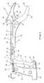
- the upper surface of the housinghas a vertically projecting hook-shaped structure serving a variety of functions.
- the integral hookaids individuals having limited mobility while putting on or removing articles of clothing, and grasping loose out-of-reach articles.
- the hookprovides a means for hanging the device from a walker, doorknob, or other structure.
- the housing, movable jaw and actuating triggereach have a lightweight, one-piece plastic molded construction facilitating device manufacturing.
- the present inventionprovides a simplified design having minimal number of parts, thereby facilitating quick and efficient assembly substantially without requiring special skills or special tools.
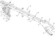
- FIG. 1is a perspective view of the device of the present invention in a fully assembled state
- FIG. 2is a perspective view of the device of the present invention with one segment of the housing being removed;
- FIG. 3is a side elevational view of the device of the present invention with one segment of the housing being removed, illustrating the device in a non-actuated, opened-jaw position;
- FIG. 4is the side elevational view of the device of the present invention with one segment of the housing being removed, illustrating the device in an actuated, closed-jaw position;
- FIG. 5is a cross-sectional view taken along a cutting plane 5 — 5 of FIG. 1;
- FIG. 6is a cross-sectional view taken along a cutting plane 6 — 6 of FIG. 1;
- FIG. 7is a cross-sectional view taken along a cutting plane 7 — 7 of FIG. 1;
- FIG. 8is a cross-sectional view taken along a cutting plane 8 — 8 of FIG. 2 .
- the present inventionis generally directed to a manually-operated pick-up device particularly useful in aiding individuals having a limited range of motion with the grasping and/or manipulation of various objects and articles.
- the assemblyhas a lightweight, simple design incorporating a limited number of parts, thereby facilitating manufacturing of the various device components and subsequent assembly of the device with minimal requirement of special tools and/or skills.
- the devicegenerally includes a rear or operating end 12 adapted for receiving the device by an operator as well as a front or object-grasping and manipulation end 14 .
- a housingis provided generally comprising an elongated shank 16 separating a handle portion 18 and a fixed jaw portion 20 .
- the housingis comprised of first and second longitudinally extending housing portions 30 and 60 , which are secured to each other by attachment arrangement. It will be discussed in full detail hereinbelow that in the preferred embodiment of the invention the attachment arrangement is in the form of a snap-fit attachment system 39 , 62 .
- a slidable actuating trigger 70is attached by a connection element 90 (see FIGS. 2-4) to a pivotally movable lower jaw 80 .
- trigger 70is squeezed by a hand of a user toward operating end 12 to effect pivotal movement of lower jaw 80 toward fixed upper jaw 20 .
- An integrally formed hooked structure 22provides additional object grasping and manipulation capability.
- the device of the present inventionresides in the device being lightweight, which is mainly achieved through the simplicity of its design.
- the deviceincorporates a minimal number of components required for its assembly and operation.
- the present inventionincorporates a housing construction which can be formed with integrally molded structural support and attachment features.
- the shank area of the first housing portion 30is generally bounded by sidewall 32 , upper perimeter wall segment 34 and lower perimeter wall segment 36 .
- the handle area of the first housing portion 30is generally defined by a front handle perimeter wall segment 52 , which is spaced from a rear handle perimeter wall segment 29 .
- a lower handle perimeter wall segment 28extends forwardly beyond the front wall segment 52 and terminates at a front edge 35 defining a foot portion.
- a trigger operational space 27is formed between the front edge 35 and wall segment 52 .
- the gap between perimeter wall segments 34 and 36is adapted to accommodate the connection element and facilitate transfer of the longitudinal motion of actuating trigger 70 into the pivotal motion of the lower jaw 80 .
- the shank area of the second housing portion 60is formed by a sidewall 62 , an upper perimeter wall segment 64 and a lower perimeter wall segment 66 .
- the handle area of the second housing portionis formed by a front handle perimeter wall segment 53 spaced from a rear perimeter wall segment. The second housing portion is aligned with the corresponding first housing portions when assembled.
- a plurality of spaced apart structures 47 having channels 48 extending at least partially therethroughcan be integrally formed along the inner surface of upper and lower perimeter walls sections 34 and 36 , and extend toward side wall 32 in a direction transverse to the longitudinally-extending shank 16 .
- the second housing portion 60can be provided having a plurality of corresponding spaced-apart projections sized and shaped for being snugly received through channels 48 during the device assembly.
- the mating projections 68 and channels 48facilitate proper alignment of the first and second housing portions, 30 and 60 , during attachment to one another. Additionally, these structures aid in minimizing relative movement of the first and second housing portions along the longitudinal plane bisecting the housing.
- tabs 38provided at spaced-apart intervals projecting laterally from edges 31 , 37 , and 51 of respective upper perimeter, lower perimeter, and handle perimeter wall segments 34 , 36 , and 52 terminate at thickened end projections 39 , which are sized and shaped for snap fitting engagement with corresponding apertures 67 formed in the second housing portion 60 .
- first housing portion 30 and second housing portion 60have been discussed hereinabove, it should be obvious to any person of ordinary skill in the art that any other means of attachment between the housing portions is within the scope of the invention.
- structures having channels extending partially therethrough as well as tabscan be formed as a part of the second housing portion, whereas the mating projections and corresponding apertures can be formed as a part of the first housing portion.
- the mating projections and channelscan be substituted by other elements performing similar functions.
- movable lower jaw member 80is provided at the front end 14 and adapted for cooperation with the fixed jaw 20 .
- the lower jaw 80is pivotally supported upon integral substantially cylindrical nub 59 extending transversely from the inner surface of the first housing sidewall 32 .
- the lower jaw member 80includes a mounting aperture having a radius defined by the inner diameter of thickened substantially cylindrical wall structure 82 and, in any event, slightly larger than the diameter of nub 59 to enable jaw member 80 to pivot smoothly and freely thereabout.
- the lower jaw member 80has a distal end portion 86 spaced from the pivot point 59 , which terminates at a serrated pincer portion 84 and cooperates with a corresponding serrated pincer portion 54 formed in the fixed jaw portion 52 during use.
- the distal end portion 86is situated within the interior of the housing, whereas the central area thereof and the pincer portion 84 extend outwardly through the opening 87 formed within the lower perimeter wall section 36 (see FIGS. 3 and 4 ).
- a trigger mechanismis provided for indirectly actuating pivotal movement of lower jaw member 80 .
- the trigger mechanismcomprises a trigger member 70 having an inverted L-shaped configuration with a longitudinally disposed upper portion 72 and a downwardly extending lower portion 74 which is transversely oriented relative to the upper portion.
- the transverse portion 74is preferably formed with finger engaging recesses 75 for facilitating gripping during use.
- Longitudinal upper portion 72is bounded at its upper and lower surfaces 71 and 73 , by projections 40 extending interiorly from upper perimeter wall segment 34 and lower perimeter wall segment 36 .
- transverse trigger portion 74At a lower end area 76 of transverse trigger portion 74 , outwardly extending projections 78 are provided. These projections are slidably guided by longitudinally disposed integral housing wall guidance structures 50 . In this manner, trigger member 70 is restricted to longitudinal movement within the first housing portion to a range of motion limited by edge 35 in the rear to front direction, as indicated by the arrow A, and the perimeter wall segment 52 in the front to rear direction, as indicated by the arrow B. Similar situation exists for second housing portion counterparts. Although two guiding structures 50 are shown in FIGS. 3 and 4, it should be understood that one structure 50 should be capable of providing the required guidance.
- a biasing member or spring 96is formed with a distal end captivated within a housing structure defined by integrally formed walls 44 , 45 and 46 , and with a proximal end received over a rearward depending nub 79 associated with the trigger member 70 .
- the biasing member 96functions to urge, or bias, the trigger in the rear to front or anterior direction.
- connection element 90having a distal end 92 and proximal end 94 is provided between the trigger member 70 and the movable jaw 80 .
- the connection element 90is attached at its distal end 92 to the trigger upper portion 72 and at its distal end 94 to the distal end portion 86 of pivotal jaw member 80 .
- the connection element 90is comprised of a substantially rigid rod-shaped member.
- the connecting rod element 90urges the lower jaw 80 to pivot in a clockwise direction about pivot point 59 . This maintains the lower jaw 80 in an open position (as best illustrated in FIG. 3 ).
- connection element 90urges lower jaw 80 to pivot in a counterclockwise direction about the pivot point 59 . This action forces the lower jaw toward a closed position (as best illustrated in FIG. 4 ).
- connection element 90is in the form of a flexible member such as a string.
- an auxiliary biasing means 98is provided for urging clockwise rotation of lower jaw 80 about pivot point 59 , or toward an open position.
- the auxiliary biasing member 98can be attached at one end thereof to an aperture 88 in the distal end portion 86 of the movable jaw 80 and at an opposite end it is connected to the inner area of the housing.
- myriad other meansare contemplated for performing this biasing function without departing from the scope of the invention.
- connection element 90is preferably substantially taut when no force is applied by the hand of an operator and trigger 70 is in a non-actuated position (as shown in FIG. 3 ).
- the connection element 90urges lower jaw 80 to pivot in a counterclockwise direction about pivot point 59 , forcing the lower jaw toward a closed position (as shown in FIG. 4 ).
- the biasing member or tensioned spring 96urges lower jaw 80 in a clockwise direction back toward its open or non-actuated position.
- the auxiliary biasing member 98can also be used with the embodiment of the invention in which the connection element 90 is in the form of a substantially rigid rod. In this application, the rearwardly positioned biasing member 96 can be eliminated.
- an integrally formed hooked portionshown generally as reference numeral 22 , is provided projecting upwardly from the device housing.
- hooked portion 22is defined, at least in part, by a tapered upper surface 56 and a curved rear surface 58 .
- hooked portion 22also forms a part of first and second housing portions 30 and 60 .
- the hook-shaped structure 22can be used to assist disabled individuals in putting on jackets, pulling up slacks or shirts, or removing socks. This is especially useful for individuals having difficulty bending, a limited range of motion, or the use of only one hand or arm.
- the hook-shaped structure 22is useful for grasping and/or manipulating hard-to-reach articles and provides a means for hanging the device from a walker, doorknob or other convenient structure.
Landscapes
- Engineering & Computer Science (AREA)
- Mechanical Engineering (AREA)
- Architecture (AREA)
- Civil Engineering (AREA)
- Structural Engineering (AREA)
- Robotics (AREA)
- Surgical Instruments (AREA)
- Purses, Travelling Bags, Baskets, Or Suitcases (AREA)
- Manipulator (AREA)
- Gripping Jigs, Holding Jigs, And Positioning Jigs (AREA)
- Eye Examination Apparatus (AREA)
- Massaging Devices (AREA)
- Accommodation For Nursing Or Treatment Tables (AREA)
- Recording Measured Values (AREA)
- Food-Manufacturing Devices (AREA)
- Accessories Of Cameras (AREA)
- Toys (AREA)
- Storage Of Fruits Or Vegetables (AREA)
Abstract
Description
Claims (15)
Priority Applications (8)
| Application Number | Priority Date | Filing Date | Title |
|---|---|---|---|
| US10/121,526US6669254B2 (en) | 2002-04-12 | 2002-04-12 | Manual pick-up device |
| CA002419671ACA2419671A1 (en) | 2002-04-12 | 2003-02-24 | Manual pick-up device |
| DE60332686TDE60332686D1 (en) | 2002-04-12 | 2003-03-18 | Hand-operated recording device |
| EP03251683AEP1352719B1 (en) | 2002-04-12 | 2003-03-18 | Manual pick-up device |
| AT03251683TATE468947T1 (en) | 2002-04-12 | 2003-03-18 | HAND-OPERATED RECORDING DEVICE |
| AU2003203535AAU2003203535B2 (en) | 2002-04-12 | 2003-04-01 | Manual pick-up device |
| JP2003108226AJP4478399B2 (en) | 2002-04-12 | 2003-04-11 | Manual gripper |
| CNB03110410XACN100360284C (en) | 2002-04-12 | 2003-04-11 | Manual pickup device |
Applications Claiming Priority (1)
| Application Number | Priority Date | Filing Date | Title |
|---|---|---|---|
| US10/121,526US6669254B2 (en) | 2002-04-12 | 2002-04-12 | Manual pick-up device |
Publications (2)
| Publication Number | Publication Date |
|---|---|
| US20030193204A1 US20030193204A1 (en) | 2003-10-16 |
| US6669254B2true US6669254B2 (en) | 2003-12-30 |
Family
ID=28454024
Family Applications (1)
| Application Number | Title | Priority Date | Filing Date |
|---|---|---|---|
| US10/121,526Expired - LifetimeUS6669254B2 (en) | 2002-04-12 | 2002-04-12 | Manual pick-up device |
Country Status (8)
| Country | Link |
|---|---|
| US (1) | US6669254B2 (en) |
| EP (1) | EP1352719B1 (en) |
| JP (1) | JP4478399B2 (en) |
| CN (1) | CN100360284C (en) |
| AT (1) | ATE468947T1 (en) |
| AU (1) | AU2003203535B2 (en) |
| CA (1) | CA2419671A1 (en) |
| DE (1) | DE60332686D1 (en) |
Cited By (60)
| Publication number | Priority date | Publication date | Assignee | Title |
|---|---|---|---|---|
| USD498998S1 (en) | 2003-02-05 | 2004-11-30 | Stephen A. Paumen | Grabbing implement |
| US20050107667A1 (en)* | 2003-05-23 | 2005-05-19 | Novare Surgical Systems, Inc. | Hand-actuated device for remote manipulation of a grasping tool |
| US20060208515A1 (en)* | 2005-03-18 | 2006-09-21 | Sierra Housewares, Inc. | Bag holder |
| US20060216975A1 (en)* | 2005-03-28 | 2006-09-28 | Dara Cheng | Spark plug boot removal tool |
| US20070035144A1 (en)* | 2005-08-12 | 2007-02-15 | Reid Industries | Pick up device with locking mechanism and leverage action trigger |
| US20070046049A1 (en)* | 2005-08-26 | 2007-03-01 | Gale Bradley D | Manually assisted reaching apparatus |
| US20070057519A1 (en)* | 2005-09-13 | 2007-03-15 | Nelson Linn E | Picking tool |
| US20070085358A1 (en)* | 2005-10-17 | 2007-04-19 | Robinson Earl F | Pick-up tool with ergonomic handle |
| USD545660S1 (en) | 2005-10-17 | 2007-07-03 | Arcoa Industries, Inc. | Handle for a pick-up tool |
| USD572551S1 (en) | 2007-05-07 | 2008-07-08 | Dehaven William | Gripping device for retrieving items from limited access areas, such as a garbage disposal |
| US20080255421A1 (en)* | 2007-04-16 | 2008-10-16 | David Elias Hegeman | Articulating tool with improved tension member system |
| USD591120S1 (en) | 2006-08-12 | 2009-04-28 | Reid Industries | Pick up device with locking mechanism and leverage action trigger |
| USD591122S1 (en) | 2006-08-12 | 2009-04-28 | Reid Industries | Pick up device with locking mechanism and leverage action trigger |
| USD591121S1 (en) | 2006-08-12 | 2009-04-28 | Reid Industries | Pick up device with locking mechanism and leverage action trigger |
| US20090274530A1 (en)* | 2008-04-30 | 2009-11-05 | Carle Robert Goodfellow | Load tie down extension arm |
| US7615066B2 (en) | 2003-05-23 | 2009-11-10 | Novare Surgical Systems, Inc. | Articulating mechanism for remote manipulation of a surgical or diagnostic tool |
| USD604577S1 (en)* | 2007-03-09 | 2009-11-24 | Unger Marketing International, Llc | Handle for a reaching and grasping tool |
| US20100021279A1 (en)* | 2008-04-11 | 2010-01-28 | Reid Industries | Pick up device with telescoping tube |
| US7678117B2 (en) | 2004-06-07 | 2010-03-16 | Novare Surgical Systems, Inc. | Articulating mechanism with flex-hinged links |
| US7785252B2 (en) | 2004-11-23 | 2010-08-31 | Novare Surgical Systems, Inc. | Articulating sheath for flexible instruments |
| US7828808B2 (en) | 2004-06-07 | 2010-11-09 | Novare Surgical Systems, Inc. | Link systems and articulation mechanisms for remote manipulation of surgical or diagnostic tools |
| US8087707B1 (en) | 2010-12-02 | 2012-01-03 | Hawkins Bryan J | Multifunction device for people with limited mobility |
| US8100824B2 (en) | 2003-05-23 | 2012-01-24 | Intuitive Surgical Operations, Inc. | Tool with articulation lock |
| US8109494B1 (en)* | 2006-09-01 | 2012-02-07 | Chick Workholding Solutions, Inc. | Workholding apparatus having a movable jaw member |
| US8182417B2 (en) | 2004-11-24 | 2012-05-22 | Intuitive Surgical Operations, Inc. | Articulating mechanism components and system for easy assembly and disassembly |
| US8257412B1 (en) | 2010-07-16 | 2012-09-04 | Skoog Thomas K | Therapy device holding system |
| US8336867B1 (en) | 2006-09-01 | 2012-12-25 | Chick Workholding Solutions, Inc. | Workholding apparatus having a detachable jaw plate |
| US8409244B2 (en) | 2007-04-16 | 2013-04-02 | Intuitive Surgical Operations, Inc. | Tool with end effector force limiter |
| US8454004B1 (en) | 2006-09-01 | 2013-06-04 | Chick Workholding Solutions, Inc. | Workholding apparatus having a movable jaw member |
| US8465475B2 (en) | 2008-08-18 | 2013-06-18 | Intuitive Surgical Operations, Inc. | Instrument with multiple articulation locks |
| US8562640B2 (en) | 2007-04-16 | 2013-10-22 | Intuitive Surgical Operations, Inc. | Tool with multi-state ratcheted end effector |
| US8573578B1 (en) | 2006-09-01 | 2013-11-05 | Chick Workholding Solutions, Inc. | Workholding apparatus |
| US8585114B2 (en) | 2012-02-22 | 2013-11-19 | Carter J. Kovarik | Selectively bendable remote gripping tool |
| USD694482S1 (en) | 2012-12-11 | 2013-11-26 | Unger Marketing International, Llc | Cleaning tool |
| US8708385B2 (en) | 2011-09-20 | 2014-04-29 | Canada Post Corporation | Reaching device |
| US8807615B2 (en) | 2012-02-22 | 2014-08-19 | Carter J. Kovarik | Selectively bendable remote gripping tool |
| US8833817B2 (en) | 2012-02-22 | 2014-09-16 | Carter J. Kovarik | Selectively bendable animal waste scooper for sanitary handling of animal droppings |
| US8985659B2 (en) | 2012-02-22 | 2015-03-24 | Carter J. Kovarik | Fish netting tool |
| US9095127B2 (en) | 2012-02-22 | 2015-08-04 | Carter J. Kovarik | Selectively bendable remote gripping tool |
| US9161771B2 (en) | 2011-05-13 | 2015-10-20 | Intuitive Surgical Operations Inc. | Medical instrument with snake wrist structure |
| US9221179B2 (en) | 2009-07-23 | 2015-12-29 | Intuitive Surgical Operations, Inc. | Articulating mechanism |
| US9227303B1 (en) | 2006-09-01 | 2016-01-05 | Chick Workholding Solutions, Inc. | Workholding apparatus |
| US9238302B2 (en) | 2013-12-02 | 2016-01-19 | David Allen Thibodeaux | Reaching aid apparatus |
| US9352451B1 (en) | 2013-05-02 | 2016-05-31 | Chick Workholding Solutions, Inc. | Workholding apparatus |
| US9561045B2 (en) | 2006-06-13 | 2017-02-07 | Intuitive Surgical Operations, Inc. | Tool with rotation lock |
| USD780547S1 (en) | 2013-08-08 | 2017-03-07 | Carter J. Kovarik | Pick up device with flexible shaft portion |
| US9592066B2 (en) | 2012-02-22 | 2017-03-14 | Carter J. Kovarik | Selectively bendable remote gripping tool |
| US9700334B2 (en) | 2004-11-23 | 2017-07-11 | Intuitive Surgical Operations, Inc. | Articulating mechanisms and link systems with torque transmission in remote manipulation of instruments and tools |
| US9832980B2 (en) | 2012-02-22 | 2017-12-05 | Carter J. Kovarik | Selectively bendable remote gripping tool |
| US9901245B2 (en) | 2012-02-22 | 2018-02-27 | Carter J. Kovarik | Selectively bendable remote gripping tool |
| US10226266B2 (en) | 2012-02-22 | 2019-03-12 | Carter J. Kovarik | Selectively bendable remote gripping tool |
| USD854901S1 (en)* | 2017-07-12 | 2019-07-30 | Nagaki Seiki Co., Ltd. | Grabber tool |
| USD876191S1 (en)* | 2017-07-12 | 2020-02-25 | Nagaki Seiki Co., Ltd. | Grabber tool |
| US11072079B1 (en) | 2020-07-24 | 2021-07-27 | Orangetherapy Llc | Suction powered pick-up stick |
| US11083475B2 (en) | 2012-02-22 | 2021-08-10 | Carter J. Kovarik | Medical device to remove an obstruction from a body lumen, vessel or organ |
| US11317926B2 (en) | 2012-08-03 | 2022-05-03 | Boss Instruments, Ltd., Inc. | Push button rongeur |
| US11497332B2 (en)* | 2020-12-08 | 2022-11-15 | Ruzhuo Zhuang | Shoe lifter with clamp |
| US20230150111A1 (en)* | 2021-11-15 | 2023-05-18 | Laura Ann Rand | Multi-Purpose Grabbing Device |
| EP4081075A4 (en)* | 2020-02-10 | 2023-12-27 | Unger Marketing International, LLC | TELESCOPIC CLAMP CAN BE FOLDED |
| US12343027B2 (en) | 2012-02-22 | 2025-07-01 | Carter J. Kovarik | Medical instruments for performing a minimally-invasive procedure |
Families Citing this family (13)
| Publication number | Priority date | Publication date | Assignee | Title |
|---|---|---|---|---|
| JP4158990B2 (en)* | 2006-02-01 | 2008-10-01 | 隆 大塚 | Fish grabber |
| CN102975152A (en)* | 2012-12-13 | 2013-03-20 | 宝钢发展有限公司 | Iron sheet attachment and transferring control device |
| CN105200950A (en)* | 2015-09-01 | 2015-12-30 | 镇江市高等专科学校 | Telescopic pickup |
| CN106932220A (en)* | 2015-12-29 | 2017-07-07 | 中核四○四有限公司 | A kind of sword formula manipulator of remote disassembling |
| CN106337386B (en)* | 2016-08-30 | 2017-12-05 | 朱新科 | A kind of gripping conveyor structure for impurity in the middle part of rail |
| CN106393048A (en)* | 2016-11-09 | 2017-02-15 | 芜湖市恒浩机械制造有限公司 | Tool for picking articles in narrow gaps |
| CN106988260B (en)* | 2017-05-19 | 2018-11-06 | 嘉兴尚云自动化设备有限公司 | A kind of sanitationman is with pickup garbage apparatus and its application method |
| CN112059158A (en)* | 2020-08-31 | 2020-12-11 | 徐云 | Manual pouring equipment for metal casting |
| CN113561152B (en)* | 2021-09-08 | 2025-07-01 | 中国科学院过程工程研究所 | A smelting furnace mechanical arm |
| CN114044345B (en)* | 2021-10-28 | 2023-07-18 | 安徽凌晗玻璃制品有限公司 | Forming device with flanging mechanism for glass teacup production |
| CN115568627B (en)* | 2022-10-14 | 2025-07-25 | 云南中烟工业有限责任公司 | A clamp-type cigarette remover |
| CN115816413B (en)* | 2023-02-15 | 2023-04-11 | 泉州壹杰科技有限公司 | An object picker that adapts to various shapes |
| CN118577913B (en)* | 2024-08-09 | 2024-11-26 | 锐宝(常州)焊割科技有限公司 | A plasma cutting gun convenient for manual control |
Citations (22)
| Publication number | Priority date | Publication date | Assignee | Title |
|---|---|---|---|---|
| US1855477A (en)* | 1930-03-24 | 1932-04-26 | Fred R Emery | Weed puller |
| US2469865A (en)* | 1946-03-13 | 1949-05-10 | Clifford O Crow | Hand tool |
| US2739008A (en)* | 1950-04-11 | 1956-03-20 | Philip F Renner | Safety-grip for package handling tongs |
| US2759758A (en)* | 1955-06-06 | 1956-08-21 | Adolphus V Yancey | Fish gaff |
| US3146015A (en)* | 1962-07-06 | 1964-08-25 | Cody Garrett | Material handling implement |
| US3885824A (en) | 1974-02-01 | 1975-05-27 | Henry J Hulst | Pickup device |
| US3937512A (en) | 1973-11-06 | 1976-02-10 | Baughman Harold E | Grab-stick for litter |
| US4037868A (en) | 1976-01-26 | 1977-07-26 | Baker Robert M | Pick up apparatus |
| US4160563A (en) | 1976-11-24 | 1979-07-10 | Whitney Donald S | Pick-up tool |
| US4208830A (en)* | 1978-11-09 | 1980-06-24 | Tomy Kogyo Co., Inc. | Mechanical hand amusement device |
| US4645253A (en)* | 1986-02-06 | 1987-02-24 | Hopec Enterprises, Inc. | Fish gripping device |
| US5029922A (en)* | 1990-02-20 | 1991-07-09 | Advanced Micro Devices, Inc. | Wafer processing cassette handle |
| US5192104A (en) | 1992-05-29 | 1993-03-09 | Lin Chin Liang | Elongated clamp |
| USD358970S (en) | 1994-03-31 | 1995-06-06 | Mayoue Robert M | Grabbing implement |
| US5570919A (en) | 1995-06-26 | 1996-11-05 | Eusebe; Frantz-Lee | Remote grapple |
| US5577785A (en) | 1995-09-11 | 1996-11-26 | Arcoa Industries | Single-hand actuated pick-up tool |
| US5590923A (en) | 1995-02-14 | 1997-01-07 | Belle De St. Claire | Interchangeable jaw tongs |
| USD386053S (en) | 1996-02-05 | 1997-11-11 | The Helping Hand Company (Ledbury) Limited | Gripping end of a hand-held gripping extension device |
| US5823590A (en) | 1997-03-20 | 1998-10-20 | Forrest; Bradley A. | Adjustable length grabber |
| US5857723A (en) | 1994-02-10 | 1999-01-12 | Stanley Mechanics Tools, Inc. | Hand tool for gripping objects |
| US5895082A (en) | 1996-08-12 | 1999-04-20 | Kaluzny; William | Manual pick up device |
| US6412840B1 (en)* | 2001-01-08 | 2002-07-02 | Wung Chin Wen | Garbage pickup tool |
Family Cites Families (12)
| Publication number | Priority date | Publication date | Assignee | Title |
|---|---|---|---|---|
| US3265429A (en)* | 1964-05-13 | 1966-08-09 | William C Shatt | Combined pick-up device and cane |
| US3527492A (en)* | 1968-06-25 | 1970-09-08 | Jimmy L Davis | Trash pick-up device |
| JPS5657212A (en)* | 1979-10-31 | 1981-05-19 | Matsushita Electric Works Ltd | Switching device for motorrdriven equipment |
| US4441746A (en)* | 1982-01-04 | 1984-04-10 | Corboy Jr Edward D | Tool for retrieving out-of-reach objects |
| JPH0616647Y2 (en)* | 1989-01-31 | 1994-05-02 | アルス刃物製造株式会社 | Remote control device using plate rod |
| CA2071229A1 (en)* | 1992-06-15 | 1993-12-16 | Ying-Ming Chiu | Magnetic pick up tool |
| JPH0615577A (en)* | 1992-06-30 | 1994-01-25 | Eimin Kyu | Magnetic picking tool for iron articles |
| CA2103507C (en)* | 1992-09-23 | 1998-09-15 | David A. Nicholas | Locking mechanism for endoscopic or laparoscopic surgical instruments |
| JPH08301569A (en)* | 1995-04-28 | 1996-11-19 | Nisshin Steel Co Ltd | Auxiliary tool for slinging work |
| DE19627970A1 (en)* | 1996-07-11 | 1998-01-15 | Gardena Kress & Kastner Gmbh | Transducer for lying goods |
| JP3047492U (en)* | 1997-09-25 | 1998-04-14 | 錦城護謨株式会社 | Auxiliary hand |
| JP2881140B1 (en)* | 1997-11-19 | 1999-04-12 | 東海旅客鉄道株式会社 | Remote control hand |
- 2002
- 2002-04-12USUS10/121,526patent/US6669254B2/ennot_activeExpired - Lifetime
- 2003
- 2003-02-24CACA002419671Apatent/CA2419671A1/ennot_activeAbandoned
- 2003-03-18ATAT03251683Tpatent/ATE468947T1/ennot_activeIP Right Cessation
- 2003-03-18EPEP03251683Apatent/EP1352719B1/ennot_activeExpired - Lifetime
- 2003-03-18DEDE60332686Tpatent/DE60332686D1/ennot_activeExpired - Lifetime
- 2003-04-01AUAU2003203535Apatent/AU2003203535B2/ennot_activeCeased
- 2003-04-11JPJP2003108226Apatent/JP4478399B2/ennot_activeExpired - Lifetime
- 2003-04-11CNCNB03110410XApatent/CN100360284C/ennot_activeExpired - Fee Related
Patent Citations (22)
| Publication number | Priority date | Publication date | Assignee | Title |
|---|---|---|---|---|
| US1855477A (en)* | 1930-03-24 | 1932-04-26 | Fred R Emery | Weed puller |
| US2469865A (en)* | 1946-03-13 | 1949-05-10 | Clifford O Crow | Hand tool |
| US2739008A (en)* | 1950-04-11 | 1956-03-20 | Philip F Renner | Safety-grip for package handling tongs |
| US2759758A (en)* | 1955-06-06 | 1956-08-21 | Adolphus V Yancey | Fish gaff |
| US3146015A (en)* | 1962-07-06 | 1964-08-25 | Cody Garrett | Material handling implement |
| US3937512A (en) | 1973-11-06 | 1976-02-10 | Baughman Harold E | Grab-stick for litter |
| US3885824A (en) | 1974-02-01 | 1975-05-27 | Henry J Hulst | Pickup device |
| US4037868A (en) | 1976-01-26 | 1977-07-26 | Baker Robert M | Pick up apparatus |
| US4160563A (en) | 1976-11-24 | 1979-07-10 | Whitney Donald S | Pick-up tool |
| US4208830A (en)* | 1978-11-09 | 1980-06-24 | Tomy Kogyo Co., Inc. | Mechanical hand amusement device |
| US4645253A (en)* | 1986-02-06 | 1987-02-24 | Hopec Enterprises, Inc. | Fish gripping device |
| US5029922A (en)* | 1990-02-20 | 1991-07-09 | Advanced Micro Devices, Inc. | Wafer processing cassette handle |
| US5192104A (en) | 1992-05-29 | 1993-03-09 | Lin Chin Liang | Elongated clamp |
| US5857723A (en) | 1994-02-10 | 1999-01-12 | Stanley Mechanics Tools, Inc. | Hand tool for gripping objects |
| USD358970S (en) | 1994-03-31 | 1995-06-06 | Mayoue Robert M | Grabbing implement |
| US5590923A (en) | 1995-02-14 | 1997-01-07 | Belle De St. Claire | Interchangeable jaw tongs |
| US5570919A (en) | 1995-06-26 | 1996-11-05 | Eusebe; Frantz-Lee | Remote grapple |
| US5577785A (en) | 1995-09-11 | 1996-11-26 | Arcoa Industries | Single-hand actuated pick-up tool |
| USD386053S (en) | 1996-02-05 | 1997-11-11 | The Helping Hand Company (Ledbury) Limited | Gripping end of a hand-held gripping extension device |
| US5895082A (en) | 1996-08-12 | 1999-04-20 | Kaluzny; William | Manual pick up device |
| US5823590A (en) | 1997-03-20 | 1998-10-20 | Forrest; Bradley A. | Adjustable length grabber |
| US6412840B1 (en)* | 2001-01-08 | 2002-07-02 | Wung Chin Wen | Garbage pickup tool |
Non-Patent Citations (1)
| Title |
|---|
| Maddak, Inc., Catalog No. 0699, pp. 62, 63, and 64, no date. |
Cited By (109)
| Publication number | Priority date | Publication date | Assignee | Title |
|---|---|---|---|---|
| USD498998S1 (en) | 2003-02-05 | 2004-11-30 | Stephen A. Paumen | Grabbing implement |
| US11547287B2 (en) | 2003-05-23 | 2023-01-10 | Intuitive Surgical Operations, Inc. | Surgical instrument |
| US9550300B2 (en) | 2003-05-23 | 2017-01-24 | Intuitive Surgical Operations, Inc. | Articulating retractors |
| US9370868B2 (en) | 2003-05-23 | 2016-06-21 | Intuitive Surgical Operations, Inc. | Articulating endoscopes |
| US9434077B2 (en) | 2003-05-23 | 2016-09-06 | Intuitive Surgical Operations, Inc | Articulating catheters |
| US9440364B2 (en) | 2003-05-23 | 2016-09-13 | Intuitive Surgical Operations, Inc. | Articulating instrument |
| US9498888B2 (en) | 2003-05-23 | 2016-11-22 | Intuitive Surgical Operations, Inc. | Articulating instrument |
| US9085085B2 (en) | 2003-05-23 | 2015-07-21 | Intuitive Surgical Operations, Inc. | Articulating mechanisms with actuatable elements |
| US10722314B2 (en) | 2003-05-23 | 2020-07-28 | Intuitive Surgical Operations, Inc. | Articulating retractors |
| US8535347B2 (en) | 2003-05-23 | 2013-09-17 | Intuitive Surgical Operations, Inc. | Articulating mechanisms with bifurcating control |
| US7615066B2 (en) | 2003-05-23 | 2009-11-10 | Novare Surgical Systems, Inc. | Articulating mechanism for remote manipulation of a surgical or diagnostic tool |
| US8100824B2 (en) | 2003-05-23 | 2012-01-24 | Intuitive Surgical Operations, Inc. | Tool with articulation lock |
| US9072427B2 (en) | 2003-05-23 | 2015-07-07 | Intuitive Surgical Operations, Inc. | Tool with articulation lock |
| US10342626B2 (en) | 2003-05-23 | 2019-07-09 | Intuitive Surgical Operations, Inc. | Surgical instrument |
| US7410483B2 (en)* | 2003-05-23 | 2008-08-12 | Novare Surgical Systems, Inc. | Hand-actuated device for remote manipulation of a grasping tool |
| US7682307B2 (en) | 2003-05-23 | 2010-03-23 | Novare Surgical Systems, Inc. | Articulating mechanism for remote manipulation of a surgical or diagnostic tool |
| US20050107667A1 (en)* | 2003-05-23 | 2005-05-19 | Novare Surgical Systems, Inc. | Hand-actuated device for remote manipulation of a grasping tool |
| US9737365B2 (en) | 2003-05-23 | 2017-08-22 | Intuitive Surgical Operations, Inc. | Tool with articulation lock |
| US9861786B2 (en) | 2004-06-07 | 2018-01-09 | Intuitive Surgical Operations, Inc. | Articulating mechanism with flex hinged links |
| US11491310B2 (en) | 2004-06-07 | 2022-11-08 | Intuitive Surgical Operations, Inc. | Articulating mechanism with flex-hinged links |
| US8920429B2 (en) | 2004-06-07 | 2014-12-30 | Intuitive Surgical Operations, Inc. | Link systems and articulation mechanisms for remote manipulation of surgical or diagnostic tools |
| US7828808B2 (en) | 2004-06-07 | 2010-11-09 | Novare Surgical Systems, Inc. | Link systems and articulation mechanisms for remote manipulation of surgical or diagnostic tools |
| US10729885B2 (en) | 2004-06-07 | 2020-08-04 | Intuitive Surgical Operations, Inc. | Articulating mechanism with flex-hinged links |
| US7678117B2 (en) | 2004-06-07 | 2010-03-16 | Novare Surgical Systems, Inc. | Articulating mechanism with flex-hinged links |
| US9095253B2 (en) | 2004-06-07 | 2015-08-04 | Intuitive Surgical Operations, Inc. | Articulating mechanism with flex hinged links |
| US9517326B2 (en) | 2004-06-07 | 2016-12-13 | Intuitive Surgical Operations, Inc. | Link systems and articulation mechanisms for remote manipulation of surgical or diagnostic tools |
| US8323297B2 (en) | 2004-06-07 | 2012-12-04 | Intuitive Surgical Operations, Inc. | Articulating mechanism with flex-hinged links |
| US8419747B2 (en) | 2004-06-07 | 2013-04-16 | Intuitive Surgical Operations, Inc. | Link systems and articulation mechanisms for remote manipulation of surgical or diagnostic tools |
| US7785252B2 (en) | 2004-11-23 | 2010-08-31 | Novare Surgical Systems, Inc. | Articulating sheath for flexible instruments |
| US10321927B2 (en) | 2004-11-23 | 2019-06-18 | Intuitive Surgical Operations, Inc. | Articulating mechanisms and link systems with torque transmission in remote manipulation of instruments and tools |
| US11638590B2 (en) | 2004-11-23 | 2023-05-02 | Intuitive Surgical Operations, Inc. | Articulating mechanisms and link systems with torque transmission in remote manipulation of instruments and tools |
| US9700334B2 (en) | 2004-11-23 | 2017-07-11 | Intuitive Surgical Operations, Inc. | Articulating mechanisms and link systems with torque transmission in remote manipulation of instruments and tools |
| US9155449B2 (en) | 2004-11-23 | 2015-10-13 | Intuitive Surgical Operations Inc. | Instrument systems and methods of use |
| US8277375B2 (en) | 2004-11-23 | 2012-10-02 | Intuitive Surgical Operations, Inc. | Flexible segment system |
| US8182417B2 (en) | 2004-11-24 | 2012-05-22 | Intuitive Surgical Operations, Inc. | Articulating mechanism components and system for easy assembly and disassembly |
| US7322624B2 (en)* | 2005-03-18 | 2008-01-29 | Sierra Housewares, Inc. | Bag holder |
| US20060208515A1 (en)* | 2005-03-18 | 2006-09-21 | Sierra Housewares, Inc. | Bag holder |
| US7243419B2 (en)* | 2005-03-28 | 2007-07-17 | Dara Cheng | Spark plug boot removal tool |
| US20060216975A1 (en)* | 2005-03-28 | 2006-09-28 | Dara Cheng | Spark plug boot removal tool |
| US9931748B2 (en) | 2005-08-12 | 2018-04-03 | Pikstik, Llc | Pick-up device with leverage action trigger |
| US20100187842A1 (en)* | 2005-08-12 | 2010-07-29 | Reid Industries | Pick up device with locking mechanism and leverage action trigger |
| US20070035144A1 (en)* | 2005-08-12 | 2007-02-15 | Reid Industries | Pick up device with locking mechanism and leverage action trigger |
| US7665782B2 (en) | 2005-08-12 | 2010-02-23 | Reid Industries | Pick up device with locking mechanism and leverage action trigger |
| US8500180B2 (en) | 2005-08-12 | 2013-08-06 | Reid Industries | Pick up device with leverage action trigger |
| US20070046049A1 (en)* | 2005-08-26 | 2007-03-01 | Gale Bradley D | Manually assisted reaching apparatus |
| US20070057519A1 (en)* | 2005-09-13 | 2007-03-15 | Nelson Linn E | Picking tool |
| US7318610B2 (en) | 2005-09-13 | 2008-01-15 | Barnel International, Inc. | Picking tool with changeable end effector |
| US20070085358A1 (en)* | 2005-10-17 | 2007-04-19 | Robinson Earl F | Pick-up tool with ergonomic handle |
| USD545660S1 (en) | 2005-10-17 | 2007-07-03 | Arcoa Industries, Inc. | Handle for a pick-up tool |
| US9561045B2 (en) | 2006-06-13 | 2017-02-07 | Intuitive Surgical Operations, Inc. | Tool with rotation lock |
| USD591120S1 (en) | 2006-08-12 | 2009-04-28 | Reid Industries | Pick up device with locking mechanism and leverage action trigger |
| USD591121S1 (en) | 2006-08-12 | 2009-04-28 | Reid Industries | Pick up device with locking mechanism and leverage action trigger |
| USD591122S1 (en) | 2006-08-12 | 2009-04-28 | Reid Industries | Pick up device with locking mechanism and leverage action trigger |
| US8905392B1 (en) | 2006-09-01 | 2014-12-09 | Chick Workholding Solutions, Inc. | Workholding apparatus having a detachable jaw plate |
| US8109494B1 (en)* | 2006-09-01 | 2012-02-07 | Chick Workholding Solutions, Inc. | Workholding apparatus having a movable jaw member |
| US8454004B1 (en) | 2006-09-01 | 2013-06-04 | Chick Workholding Solutions, Inc. | Workholding apparatus having a movable jaw member |
| US8336867B1 (en) | 2006-09-01 | 2012-12-25 | Chick Workholding Solutions, Inc. | Workholding apparatus having a detachable jaw plate |
| US10040173B1 (en) | 2006-09-01 | 2018-08-07 | Chick Workholding Solutions, Inc. | Workholding apparatus having a detachable jaw plate |
| US9227303B1 (en) | 2006-09-01 | 2016-01-05 | Chick Workholding Solutions, Inc. | Workholding apparatus |
| US8573578B1 (en) | 2006-09-01 | 2013-11-05 | Chick Workholding Solutions, Inc. | Workholding apparatus |
| USD604577S1 (en)* | 2007-03-09 | 2009-11-24 | Unger Marketing International, Llc | Handle for a reaching and grasping tool |
| USD617619S1 (en) | 2007-03-09 | 2010-06-15 | Unger Marketing International, Llc | Gripper for reaching and grasping tool |
| US7862554B2 (en) | 2007-04-16 | 2011-01-04 | Intuitive Surgical Operations, Inc. | Articulating tool with improved tension member system |
| US8562640B2 (en) | 2007-04-16 | 2013-10-22 | Intuitive Surgical Operations, Inc. | Tool with multi-state ratcheted end effector |
| US20080255421A1 (en)* | 2007-04-16 | 2008-10-16 | David Elias Hegeman | Articulating tool with improved tension member system |
| US8409244B2 (en) | 2007-04-16 | 2013-04-02 | Intuitive Surgical Operations, Inc. | Tool with end effector force limiter |
| USD572551S1 (en) | 2007-05-07 | 2008-07-08 | Dehaven William | Gripping device for retrieving items from limited access areas, such as a garbage disposal |
| US9004563B2 (en) | 2008-04-11 | 2015-04-14 | Pikstik, Llc | Pick up device with telescoping tube |
| US9486915B2 (en) | 2008-04-11 | 2016-11-08 | Pikstik, Llc | Pick up device with telescoping tube |
| US20100021279A1 (en)* | 2008-04-11 | 2010-01-28 | Reid Industries | Pick up device with telescoping tube |
| US20090274530A1 (en)* | 2008-04-30 | 2009-11-05 | Carle Robert Goodfellow | Load tie down extension arm |
| US7900985B2 (en)* | 2008-04-30 | 2011-03-08 | Carle Robert Goodfellow | Load securing extension arm |
| US9737298B2 (en) | 2008-08-18 | 2017-08-22 | Intuitive Surgical Operations, Inc. | Instrument with articulation lock |
| US11998195B2 (en) | 2008-08-18 | 2024-06-04 | Intuitive Surgical Operations, Inc. | Instrument with multiple articulation locks |
| US9033960B2 (en) | 2008-08-18 | 2015-05-19 | Intuitive Surgical Operations, Inc. | Instrument with multiple articulation locks |
| US11234694B2 (en) | 2008-08-18 | 2022-02-01 | Intuitive Surgical Operations, Inc. | Instrument with multiple articulation locks |
| US8465475B2 (en) | 2008-08-18 | 2013-06-18 | Intuitive Surgical Operations, Inc. | Instrument with multiple articulation locks |
| US9221179B2 (en) | 2009-07-23 | 2015-12-29 | Intuitive Surgical Operations, Inc. | Articulating mechanism |
| US8257412B1 (en) | 2010-07-16 | 2012-09-04 | Skoog Thomas K | Therapy device holding system |
| US8087707B1 (en) | 2010-12-02 | 2012-01-03 | Hawkins Bryan J | Multifunction device for people with limited mobility |
| US11357526B2 (en) | 2011-05-13 | 2022-06-14 | Intuitive Surgical Operations, Inc. | Medical instrument with snake wrist structure |
| US10335177B2 (en) | 2011-05-13 | 2019-07-02 | Intuitive Surgical Operations, Inc. | Medical instrument with snake wrist structure |
| US9161771B2 (en) | 2011-05-13 | 2015-10-20 | Intuitive Surgical Operations Inc. | Medical instrument with snake wrist structure |
| US9296343B2 (en) | 2011-09-20 | 2016-03-29 | Canada Post Corporation | Restraining device |
| US8708385B2 (en) | 2011-09-20 | 2014-04-29 | Canada Post Corporation | Reaching device |
| US11083475B2 (en) | 2012-02-22 | 2021-08-10 | Carter J. Kovarik | Medical device to remove an obstruction from a body lumen, vessel or organ |
| US8985659B2 (en) | 2012-02-22 | 2015-03-24 | Carter J. Kovarik | Fish netting tool |
| US8585114B2 (en) | 2012-02-22 | 2013-11-19 | Carter J. Kovarik | Selectively bendable remote gripping tool |
| US9095127B2 (en) | 2012-02-22 | 2015-08-04 | Carter J. Kovarik | Selectively bendable remote gripping tool |
| US8833817B2 (en) | 2012-02-22 | 2014-09-16 | Carter J. Kovarik | Selectively bendable animal waste scooper for sanitary handling of animal droppings |
| US12343027B2 (en) | 2012-02-22 | 2025-07-01 | Carter J. Kovarik | Medical instruments for performing a minimally-invasive procedure |
| US8807615B2 (en) | 2012-02-22 | 2014-08-19 | Carter J. Kovarik | Selectively bendable remote gripping tool |
| US9901245B2 (en) | 2012-02-22 | 2018-02-27 | Carter J. Kovarik | Selectively bendable remote gripping tool |
| US9592066B2 (en) | 2012-02-22 | 2017-03-14 | Carter J. Kovarik | Selectively bendable remote gripping tool |
| US11896252B2 (en) | 2012-02-22 | 2024-02-13 | Carter J. Kovarik | Medical device to remove an obstruction from a body lumen, vessel or organ |
| US9832980B2 (en) | 2012-02-22 | 2017-12-05 | Carter J. Kovarik | Selectively bendable remote gripping tool |
| US10226266B2 (en) | 2012-02-22 | 2019-03-12 | Carter J. Kovarik | Selectively bendable remote gripping tool |
| US11317926B2 (en) | 2012-08-03 | 2022-05-03 | Boss Instruments, Ltd., Inc. | Push button rongeur |
| USD694482S1 (en) | 2012-12-11 | 2013-11-26 | Unger Marketing International, Llc | Cleaning tool |
| US9352451B1 (en) | 2013-05-02 | 2016-05-31 | Chick Workholding Solutions, Inc. | Workholding apparatus |
| USD780547S1 (en) | 2013-08-08 | 2017-03-07 | Carter J. Kovarik | Pick up device with flexible shaft portion |
| US9238302B2 (en) | 2013-12-02 | 2016-01-19 | David Allen Thibodeaux | Reaching aid apparatus |
| USD876191S1 (en)* | 2017-07-12 | 2020-02-25 | Nagaki Seiki Co., Ltd. | Grabber tool |
| USD854901S1 (en)* | 2017-07-12 | 2019-07-30 | Nagaki Seiki Co., Ltd. | Grabber tool |
| EP4081075A4 (en)* | 2020-02-10 | 2023-12-27 | Unger Marketing International, LLC | TELESCOPIC CLAMP CAN BE FOLDED |
| US12023797B2 (en) | 2020-02-10 | 2024-07-02 | Unger Marketing International, Llc | Foldable reaching and grasping tool |
| US11072079B1 (en) | 2020-07-24 | 2021-07-27 | Orangetherapy Llc | Suction powered pick-up stick |
| US11497332B2 (en)* | 2020-12-08 | 2022-11-15 | Ruzhuo Zhuang | Shoe lifter with clamp |
| US20230150111A1 (en)* | 2021-11-15 | 2023-05-18 | Laura Ann Rand | Multi-Purpose Grabbing Device |
Also Published As
| Publication number | Publication date |
|---|---|
| CN1478636A (en) | 2004-03-03 |
| CA2419671A1 (en) | 2003-10-12 |
| EP1352719B1 (en) | 2010-05-26 |
| JP4478399B2 (en) | 2010-06-09 |
| US20030193204A1 (en) | 2003-10-16 |
| CN100360284C (en) | 2008-01-09 |
| EP1352719A3 (en) | 2005-06-22 |
| ATE468947T1 (en) | 2010-06-15 |
| AU2003203535A1 (en) | 2003-11-06 |
| DE60332686D1 (en) | 2010-07-08 |
| AU2003203535B2 (en) | 2008-11-20 |
| JP2003311633A (en) | 2003-11-05 |
| EP1352719A2 (en) | 2003-10-15 |
Similar Documents
| Publication | Publication Date | Title |
|---|---|---|
| US6669254B2 (en) | Manual pick-up device | |
| US6874833B2 (en) | Pickup tool with variable position limiting and variable axis of operation | |
| US6951224B2 (en) | Walking support having shoehorn/gripper and magnet accessories | |
| US4709839A (en) | Shoe butler with heel gripping device | |
| US7975886B2 (en) | Sock donning system | |
| US4299246A (en) | Walking aids | |
| US6508496B1 (en) | Manually-operated device for picking up objects | |
| US4827956A (en) | Remote grasping device | |
| US6158077A (en) | Personal hygiene appliance | |
| US5554161A (en) | Tick removal tool | |
| US20100264678A1 (en) | Introduction of the panther multi task tool | |
| US6578397B1 (en) | Combined small object-assist device | |
| JP2001286382A (en) | Freely opening/shutting hanger capable of secure operation with one hand | |
| US20100064528A1 (en) | Scissors for accommodating different sized hands and for requiring a minimal force to close | |
| JP4788933B2 (en) | Shoe remover / cane and shoehorn used for the shoe remover / cane | |
| JP4871602B2 (en) | Cane | |
| US20060137247A1 (en) | Opening device | |
| US6776648B1 (en) | Electrical plug installer and remover | |
| JP2523134B2 (en) | Weed remover | |
| US5822805A (en) | Toilet flush actuator | |
| JP3065259U (en) | umbrella | |
| US7870627B2 (en) | Method and apparatus to stretch shoe uppers | |
| JPS639426Y2 (en) | ||
| JP2002209617A (en) | Stick with reacher | |
| WO2011117611A1 (en) | Serving device |
Legal Events
| Date | Code | Title | Description |
|---|---|---|---|
| AS | Assignment | Owner name:BEL-ART PRODUCTS, INC., NEW JERSEY Free format text:ASSIGNMENT OF ASSIGNORS INTEREST;ASSIGNORS:THOM, PAUL;LANDSBERGER, DAVID;GOMES, FRANCIS;REEL/FRAME:013152/0211 Effective date:20020717 | |
| REMI | Maintenance fee reminder mailed | ||
| FEPP | Fee payment procedure | Free format text:PETITION RELATED TO MAINTENANCE FEES GRANTED (ORIGINAL EVENT CODE: PMFG); ENTITY STATUS OF PATENT OWNER: SMALL ENTITY Free format text:PETITION RELATED TO MAINTENANCE FEES FILED (ORIGINAL EVENT CODE: PMFP); ENTITY STATUS OF PATENT OWNER: SMALL ENTITY | |
| REIN | Reinstatement after maintenance fee payment confirmed | ||
| PRDP | Patent reinstated due to the acceptance of a late maintenance fee | Effective date:20080221 | |
| FP | Lapsed due to failure to pay maintenance fee | Effective date:20071230 | |
| FPAY | Fee payment | Year of fee payment:4 | |
| STCF | Information on status: patent grant | Free format text:PATENTED CASE | |
| SULP | Surcharge for late payment | ||
| FPAY | Fee payment | Year of fee payment:8 | |
| FPAY | Fee payment | Year of fee payment:12 | |
| AS | Assignment | Owner name:ANTARES CAPITAL LP, AS AGENT, ILLINOIS Free format text:SECURITY INTEREST;ASSIGNORS:SP INDUSTRIES, INC.;BEL-ART PRODUCTS;APPLIED COATINGS, INC.;AND OTHERS;REEL/FRAME:037237/0647 Effective date:20151208 | |
| AS | Assignment | Owner name:BEL-ART PRODUCTS, NEW JERSEY Free format text:RELEASE BY SECURED PARTY;ASSIGNOR:BANK OF MONTREAL;REEL/FRAME:037331/0559 Effective date:20151208 Owner name:SP INDUSTRIES, INC., PENNSYLVANIA Free format text:RELEASE BY SECURED PARTY;ASSIGNOR:BANK OF MONTREAL;REEL/FRAME:037331/0559 Effective date:20151208 Owner name:MADDAK, INC., NEW JERSEY Free format text:RELEASE BY SECURED PARTY;ASSIGNOR:BANK OF MONTREAL;REEL/FRAME:037331/0559 Effective date:20151208 Owner name:GENEVAC, INC., NEW YORK Free format text:RELEASE BY SECURED PARTY;ASSIGNOR:BANK OF MONTREAL;REEL/FRAME:037331/0559 Effective date:20151208 |