US6669072B2 - Flywheel operated nailer - Google Patents
Flywheel operated nailerDownload PDFInfo
- Publication number
- US6669072B2 US6669072B2US10/027,174US2717401AUS6669072B2US 6669072 B2US6669072 B2US 6669072B2US 2717401 AUS2717401 AUS 2717401AUS 6669072 B2US6669072 B2US 6669072B2
- Authority
- US
- United States
- Prior art keywords
- cam plate
- activation
- drum
- flywheel
- tool
- Prior art date
- Legal status (The legal status is an assumption and is not a legal conclusion. Google has not performed a legal analysis and makes no representation as to the accuracy of the status listed.)
- Expired - Fee Related, expires
Links
- 230000004913activationEffects0.000claimsabstractdescription56
- 230000007246mechanismEffects0.000claimsabstractdescription16
- 230000006835compressionEffects0.000claimsabstractdescription6
- 238000007906compressionMethods0.000claimsabstractdescription6
- 238000000926separation methodMethods0.000claimsdescription6
- 125000004122cyclic groupChemical group0.000abstractdescription5
- 125000006850spacer groupChemical group0.000description3
- 238000009825accumulationMethods0.000description2
- 238000009432framingMethods0.000description2
- 238000000034methodMethods0.000description2
- 230000003213activating effectEffects0.000description1
- 230000006978adaptationEffects0.000description1
- 238000010304firingMethods0.000description1
- 238000012986modificationMethods0.000description1
- 230000004048modificationEffects0.000description1
- 230000002093peripheral effectEffects0.000description1
- 238000007789sealingMethods0.000description1
- 238000009987spinningMethods0.000description1
- 238000004804windingMethods0.000description1
- 239000002023woodSubstances0.000description1
Images


Classifications
- B—PERFORMING OPERATIONS; TRANSPORTING
- B25—HAND TOOLS; PORTABLE POWER-DRIVEN TOOLS; MANIPULATORS
- B25C—HAND-HELD NAILING OR STAPLING TOOLS; MANUALLY OPERATED PORTABLE STAPLING TOOLS
- B25C1/00—Hand-held nailing tools; Nail feeding devices
- B25C1/06—Hand-held nailing tools; Nail feeding devices operated by electric power
- H—ELECTRICITY
- H02—GENERATION; CONVERSION OR DISTRIBUTION OF ELECTRIC POWER
- H02P—CONTROL OR REGULATION OF ELECTRIC MOTORS, ELECTRIC GENERATORS OR DYNAMO-ELECTRIC CONVERTERS; CONTROLLING TRANSFORMERS, REACTORS OR CHOKE COILS
- H02P27/00—Arrangements or methods for the control of AC motors characterised by the kind of supply voltage
- H02P27/04—Arrangements or methods for the control of AC motors characterised by the kind of supply voltage using variable-frequency supply voltage, e.g. inverter or converter supply voltage
- H02P27/047—V/F converter, wherein the voltage is controlled proportionally with the frequency
Definitions
- the herein disclosed and taught inventiongenerally relates to a cyclic operating tool employing an energized flywheel to provide the necessary energy to perform a working cycle.
- the invention disclosed hereinrelates to, but is not necessarily limited to, a hand held electromechanical fastener driving tool, such as a fastener driving tool having an electrically powered motor energizing a flywheel which provides the necessary kinetic energy to drive a fastener into a work piece.
- the electrical powermay be provided by either a battery or an AC electrical power source.
- pneumatic driving toolsrequire an on-site air compressor
- corded electric toolsrequire an on-site source of electrical power.
- both type of toolsrequire the user to drag a pneumatic or electrical umbilical behind them during use. Dragging such an umbilical behind becomes particularly troublesome when working in high places such as upon a roof or a ladder.
- Electrically driven toolssuch as solenoid operated fastener driving tools, are also well known. These are primarily used in lighter duty applications such as in driving one inch brad nails, for example, rather than the larger 1.25 to 2.5, 15 gauge finishing nails and/or heavier framing nails.
- the present inventiondiscloses and teaches a novel drive mechanism particularly useful in a cyclic hand tool, which has an operative work cycle followed by a reset cycle such as a powered nailing machine. More particularly the present invention is useful in a cyclic tool employing the kinetic energy of an energized flywheel to provide the necessary energy to perform the tool's operative working cycle.
- a drive mechanismis taught whereby a first pair of rotatable caming plates, activated by an electrical solenoid, cause a clutch assembly to engage an energized flywheel.
- a second pair of rotatable caming platesactivated by the flywheel, affect the compression of a spring whereby additional force is imposed upon the clutch ensuring slip free engagement during the following operative work cycle of the drive mechanism.
- the second pair of caming platesaffect a rapid disengagement of the clutch from the flywheel whereby the drive mechanism returns to its start position and the flywheel dissipates its remaining energy by free wheeling until it stops or until it is re-energized for an additional work cycle.
- the present inventionis also used in a corded electric motor embodiment. Further it is to be understood that the present invention is also suitable for applications, other than hand held tools, where a cyclic operation, similar to that of a hand held nailing machine, is desired.
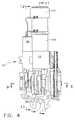
- FIG. 1presents a left side elevational view of a hand held nailing machine, embodying the present invention, having a portion of its left side removed to show the general positioning of the driving mechanism within the tool's outer shell.
- FIG. 2presents a top view of the fastener drive assembly removed from the main body of the hand held nailing machine as illustrated in figure.
- FIG. 3presents a left side elevational view of the fastener drive assembly as removed from the nailing machine illustrated in FIG. 1 .
- FIG. 4presents a bottom view, looking upward from the handle of the fastener drive assembly as removed from the nailing machine outer shell illustrated in FIG. 1 and having the electrical control module removed for clarity.
- FIG. 5presents an end elevational view of the fastener drive assembly as removed from the nailing machine illustrated in FIG. 1 and having the electrical control module removed for clarity.
- FIG. 6presents a pictorial view of the fastener drive assembly, having the electrical control module removed for clarity, showing the general arrangement the clutch drive assembly components.
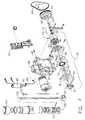
- FIG. 7presents an exploded pictorial view showing the components of the fastener drive assembly illustrated in FIGS. 2 through 6.
- FIG. 8presents a sectional view taken along line 8 — 8 in FIG. 3 .
- FIG. 9presents a sectional view taken along line 9 — 9 in FIG. 4 .
- FIG. 10is a enlarged top section of the cylinder as shown in FIG. 11 .
- FIG. 11is a cross-sectional view taken along line 11 — 11 in FIG. 4 .
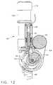
- FIG. 12is a sectional view taken along line 12 — 12 in FIG. 4 .
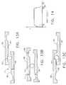
- FIGS. 13A through 13Cpresent a schematical presentation of the ball/cam action between the fixed plate an the activation plate.
- FIG. 14presents a graph showing the distance x between the fixed plate and the actuation plate as a function of degrees of rotation of the actuation plate.
- FIG. 15presents an expanded pictorial view of the solenoid camming plates.
- FIG. 16presents an expanded pictorial view of the activation camming plates.
- the hand toolmay also be powered by a corded AC electric motor in place of the battery powered DC motor described herein.
- FIG. 1illustrates a hand held nailing machine 10 generally comprising a main body 12 including and a gripping handle 14 . Attached to the end of handle 14 is removable, rechargeable battery 19 for providing the necessary electrical energy to operate the nailing machine power drive mechanism. Also included in handle 14 is trigger 16 for operating nailing machine 10 .
- a fastener supplying magazine assembly 18is typically attached to main body 12 and handle 14 , as illustrated, for supplying a strip of fasteners to nose assembly 20 .
- FIGS. 2, 3 , 4 , and 5illustrate top, left side, bottom and rear views of fastener drive assembly 40 as positioned within housing 12 of nailing machine 10 illustrated in FIG. 1 .
- FIGS. 2, 4 , and 5have electrical control module 25 removed for clarity. The structural details and operation of control module 25 is completely described within the two copending patent applications identified in the “Related Patent Applications” section above and are incorporated herein by reference.
- fastener drive assembly 40comprises a flywheel 45 for providing kinetic energy, for driving a fastener into a work piece, energized by an electric motor 42 by of drive belt 64 .
- Flywheel 45is free wheeling upon fixed shaft 32 .
- drive clutch assembly 30Upon achieving the required revolutions per minute (RPM), drive clutch assembly 30 (see FIGS. 7 and 9) causes engagement of clutch assembly 35 and flywheel 45 thereby transferring a portion of the kinetic energy of flywheel 45 to a linearly moving driver 106 for driving a fastener into a work piece.
- the flywheel drive assemblycomprises clutch drive assembly 30 and flywheel 45 gear driven by electric motor 42 by way of belt 64 .
- flywheel 45 and clutch drive assembly 30will be operationally described.
- Clutch drive assembly 30 and flywheel 45are axially aligned upon central shaft 32 as best illustrated in FIG. 9 .
- Central shaft 32is threadingly affixed to end plate 52 which in turn is rigidly attached to frame 48 by an integral boss 51 extending axially from endplate 52 and received within slotted groove 47 such that end plate 52 and central shaft 32 are non-rotatable.
- the opposite end of central shaft 32is received within supporting groove 49 in frame 48 .
- Flywheel 45is rotatingly positioned at the end of central shaft 32 , as best illustrated in FIG. 9, upon deep groove ball bearings 46 , whereby flywheel 45 freely rotates about central shaft 32 when energized by motor 42 .
- Flywheel 45includes an internal, conical projection 44 for receiving thereon concave, conical friction surface 36 of integral clutch/drum assembly 35 .
- Clutch/drum assembly 35comprises a bell shaped end 34 having friction surface 36 therein and axially opposite of bell shaped end 34 is a cable winding portion 57 upon which activating cable 102 is wound during the power stroke of tool 10 as is described in further detail below.
- Clutch/drum assembly 35 and activation plate 58are geared together by interlocking projection 28 whereby clutch/drum assembly 35 and activation plate 58 rotate freely about shaft 32 as a single unitary assembly.
- Roller bearings 38 A and 38 Bpositioned on the inside diameter of clutch/drum drum 35 , are provided to assure the free rotational characteristic of activation plate 58 ,and clutch ⁇ drum 35 as a unitary assembly.
- Adjacent activation plate 58is fixed plate 56 .
- Fixed plate 56 and activation plate 58are connected to one another by three equally spaced axially expandable ball ramps 66 A, 66 B, 66 C, 66 A′, 66 B′ and 66 C′ as illustrated in FIG. 16 .
- the operation of the ball ramps 66 between fixed plate 56 and activation plate 58is described in greater detail below.
- Fixed plate 56is fixed to housing 48 such that fixed plate 56 is free to move axially upon central shaft 32 , but not free to rotate about shaft 32 by anti-rotation tang 53 slidably received within axially aligned slot 43 within frame 48 . See FIG. 9 .
- Fixed plate 56includes circular projection 61 receiving thereon freely rotatable thrust bearing 62 positioned between fixed plate 56 and Belleville spring 72 .
- Belleville spring 72is positioned, as illustrated in FIG. 9, between spacer 64 and thrust bearing 62 the function of which is described in greater detail below.
- compression spring assembly 37Positioned upon central shaft 32 , between clutch/drum 35 and flywheel 45 is compression spring assembly 37 comprising spacers 73 and 74 having coil spring 75 therebetween the function of which is described in further detail below.
- control microprocessor 25Upon start of the fastener work, or driving, cycle, control microprocessor 25 causes motor 42 to “spin up” flywheel 45 , in the counter clockwise direction as indicated by arrow A in FIG. 7, to a predetermined RPM. Upon flywheel 45 achieving its desired RPM, or kinetic energy state, control microprocessor 25 activates solenoid 80 which, through a flexible wire cable 84 extending from the solenoid plunger 82 and affixed to the periphery of solenoid plate 54 , see FIG. 10, causes solenoid plate 54 to rotate clockwise, as indicated by arrow B in FIG. 7 .
- solenoid plate 54As solenoid plate 54 rotates clockwise, solenoid plate 54 is caused to move axially away from end plate 52 by action of the corresponding ball ramps 68 in end plate 52 and solenoid plate 54 . See FIG. 15 . As end plate 52 and solenoid plate 54 axially separate, the remaining elements of clutch drive assembly 30 are thereby caused to move axially toward flywheel 45 compressing coil spring 75 whereby clutch surface 36 preliminarily engages flywheel 45 . Engagement of clutch friction surface 36 , with flywheel 45 , causes counter clockwise rotation of clutch/drum 35 and activation plate 58 , as an assembly. By action of corresponding ball ramps 66 , between fixed plate 56 and activation plate 58 , see FIG. 16, rotation of activation plate 58 causes axial separation of plates 53 and 58 . Bellville spring 72 is thus compressed against spacer 64 thereby providing an opposite axial force, forcing clutch/drum 35 into tighter engagement with flywheel 45 .
- control microprocessor 25Upon sensing an RPM drop of flywheel 45 , the control microprocessor 25 shuts off solenoid 80 , whereby solenoid plate 54 begins to return to its reset position by action of the axial force applied by the compressed Belleville spring 72 .
- FIGS. 13A through 13Csequentially illustrate the action between fixed plate 56 and activation plate 58 as plate 58 rotates during the power stroke.
- ball ramps 66 of fixed plate 56 and activation plate 58are helical as illustrated in FIG. 16, ramps 66 are illustrated as being linear in FIGS. 13A through 13C for simplicity of explanation.
- FIG. 13Aillustrates fixed plate 56 and activation plate 58 at the beginning of the tool's work cycle.
- flywheel 45drives activation plate 58 counter clockwise (to the left in FIG. 13A) balls 63 , following ramp profile 66 , cause a fast and sudden separation x, between activation plate 58 and fixed plate 56 as illustrated in FIG. 13 B. Separation x is maintained throughout the power stroke of driver 106 , as illustrated in FIG. 13B, thereby affecting the impartion of the kinetic energy, stored within flywheel 45 , to driver 106 as described above.
- plates 56 and 58suddenly close together thereby causing the rapid disengagement of clutch/drum 35 from flywheel 45 .
- FIG. 14presents a representative graphical plot of the separation x between activation plate 58 and fixed plate 56 as a function of the angle of rotation of activation plate 58 .
- a combination driver guide and resilient stop block 108is preferably positioned at the bottom of cylinder 110 to stop piston assembly 111 , within cylinder 100 , at the end of the power stroke.
- coil spring 75urges all elements of clutch drive assembly 30 back toward end plate 52 .
- clutch/drum 35disengages from flywheel 45 thereby allowing flywheel 45 to continue spinning after drive assembly 30 has reached the end of its power stroke .
- the remaining kinetic energyis available for the subsequent operation thereby economizing battery power and saving the drive assembly elements and/or the frame 48 from having to absorb the impact that would otherwise occur by bringing flywheel 45 to a full stop immediately after the power stroke.
- This featurealso permits “dry firing” of the tool.
- the clutch drive system as taught hereinalso provides for automatic compensation for clutch wear in that the expansion between end plate 52 and solenoid plate 54 will continue until clutch/drum 35 engages flywheel 45 thereby allowing solenoid plate 54 to take up the difference at the start of every power drive.
- piston 112includes circumferential groove 132 receiving therein a generally rectangular shaped seal 134 having a V shaped groove 136 in one laterally positioned side thereof.
- seal 134acts as a check valve such that as piston 112 moves downward, during a power stroke, leg 133 sealing engages the inside wall of cylinder 100 preventing the passage of air past piston 112 thereby creating the desired vacuum above piston 112 .
- drum 34returns to its start position tang 33 , radially extending from drum 34 , engages abutment block 31 affixed to housing 48 , see FIG. 6, thereby preventing over travel of drum/clutch 35 as it returns to its start position.
Landscapes
- Engineering & Computer Science (AREA)
- Mechanical Engineering (AREA)
- Portable Nailing Machines And Staplers (AREA)
Abstract
Description
Claims (23)
Priority Applications (5)
| Application Number | Priority Date | Filing Date | Title |
|---|---|---|---|
| US10/027,174US6669072B2 (en) | 2000-12-22 | 2001-12-20 | Flywheel operated nailer |
| CA 2432996CA2432996A1 (en) | 2000-12-22 | 2001-12-21 | Flywheel opperated nailer |
| EP01992285AEP1349712A1 (en) | 2000-12-22 | 2001-12-21 | Flywheel opperated nailer |
| JP2002552721AJP2004535303A (en) | 2000-12-22 | 2001-12-21 | Flywheel operated nailing machine |
| PCT/US2001/049890WO2002051595A1 (en) | 2000-12-22 | 2001-12-21 | Flywheel opperated nailer |
Applications Claiming Priority (2)
| Application Number | Priority Date | Filing Date | Title |
|---|---|---|---|
| US25802200P | 2000-12-22 | 2000-12-22 | |
| US10/027,174US6669072B2 (en) | 2000-12-22 | 2001-12-20 | Flywheel operated nailer |
Publications (2)
| Publication Number | Publication Date |
|---|---|
| US20020108994A1 US20020108994A1 (en) | 2002-08-15 |
| US6669072B2true US6669072B2 (en) | 2003-12-30 |
Family
ID=26702157
Family Applications (1)
| Application Number | Title | Priority Date | Filing Date |
|---|---|---|---|
| US10/027,174Expired - Fee RelatedUS6669072B2 (en) | 2000-12-22 | 2001-12-20 | Flywheel operated nailer |
Country Status (5)
| Country | Link |
|---|---|
| US (1) | US6669072B2 (en) |
| EP (1) | EP1349712A1 (en) |
| JP (1) | JP2004535303A (en) |
| CA (1) | CA2432996A1 (en) |
| WO (1) | WO2002051595A1 (en) |
Cited By (56)
| Publication number | Priority date | Publication date | Assignee | Title |
|---|---|---|---|---|
| USD499321S1 (en) | 2004-03-12 | 2004-12-07 | Black & Decker Inc. | Fastener tool |
| US20050217875A1 (en)* | 2004-04-02 | 2005-10-06 | Michael Forster | Method for controlling a power driver |
| US20050242154A1 (en)* | 2004-04-30 | 2005-11-03 | Leimbach Richard L | Cordless fastener driving tool |
| US6971567B1 (en)* | 2004-10-29 | 2005-12-06 | Black & Decker Inc. | Electronic control of a cordless fastening tool |
| WO2005097416A3 (en)* | 2004-04-02 | 2006-08-17 | Black & Decker Inc | Method for sizing a motor for a power tool |
| US20060196911A1 (en)* | 2005-03-02 | 2006-09-07 | Pei-Li Sun | Electric nailing apparatus |
| USD527972S1 (en)* | 2004-04-30 | 2006-09-12 | Black & Decker, Inc. | Pneumatic fastener |
| US7165305B2 (en)* | 2004-04-02 | 2007-01-23 | Black & Decker Inc. | Activation arm assembly method |
| US20070095876A1 (en)* | 2005-10-28 | 2007-05-03 | Hiroyuki Oda | Electric fastener driver |
| WO2005098886A3 (en)* | 2004-04-02 | 2007-07-19 | Black & Decker Inc | Method for controlling a power driver |
| US20070210134A1 (en)* | 2006-03-09 | 2007-09-13 | Hiroyuki Oda | Portable driver |
| USD560108S1 (en) | 2005-07-19 | 2008-01-22 | Milwaukee Electric Tool Corporation | Power tool, such as a nailer |
| US20080067213A1 (en)* | 2006-09-14 | 2008-03-20 | Yukihiro Shima | Electric driving machine |
| US20080223894A1 (en)* | 2007-03-16 | 2008-09-18 | Black & Decker Inc. | Driving tool and method for controlling same |
| US20090032566A1 (en)* | 2007-08-03 | 2009-02-05 | Chia-Sheng Liang | Transmission Mechanism for Electrical Nail Gun |
| US20090032567A1 (en)* | 2007-08-03 | 2009-02-05 | Chia-Sheng Liang | Clutch Mechanism for Electrical Nail Gun |
| US20090039136A1 (en)* | 2005-09-30 | 2009-02-12 | Hideyuki Tanimoto | Electric fastener driver |
| US20090095787A1 (en)* | 2007-10-12 | 2009-04-16 | Chia-Sheng Liang | Transmission Mechanism for Electric Nail Gun |
| US7556184B2 (en) | 2007-06-11 | 2009-07-07 | Black & Decker Inc. | Profile lifter for a nailer |
| US20090188766A1 (en)* | 2008-01-15 | 2009-07-30 | Hitachi Koki Co., Ltd. | Fastener driving tool |
| US20090194573A1 (en)* | 2008-02-04 | 2009-08-06 | Chia-Sheng Liang | Actuator for Electrical Nail Gun |
| US20090250500A1 (en)* | 2008-04-03 | 2009-10-08 | Brendel Lee M | Cordless framing nailer |
| US20090266863A1 (en)* | 2005-09-30 | 2009-10-29 | Hideki Ishida | Portable fastening tool |
| US20100038395A1 (en)* | 2008-08-14 | 2010-02-18 | Credo Technology Corporation | Cordless Nailer With Safety Sensor |
| US20100213232A1 (en)* | 2009-02-20 | 2010-08-26 | Credo Technology Corporation | Nailer with brushless dc motor |
| US20110048752A1 (en)* | 2007-10-02 | 2011-03-03 | Shinichiro Sato | Power Tool |
| US20110094847A1 (en)* | 2007-08-27 | 2011-04-28 | Makita Corporation | Driving tool |
| US8002160B2 (en) | 2004-08-30 | 2011-08-23 | Black & Decker Inc. | Combustion fastener |
| US20120074195A1 (en)* | 2010-09-28 | 2012-03-29 | Basso Industry Corp. | Driving unit for an electric nail gun |
| US20120080283A1 (en)* | 2010-09-30 | 2012-04-05 | Lang David J | Cone brake load limiter method and apparatus |
| US8231039B2 (en) | 2004-04-02 | 2012-07-31 | Black & Decker Inc. | Structural backbone/motor mount for a power tool |
| US8302833B2 (en) | 2004-04-02 | 2012-11-06 | Black & Decker Inc. | Power take off for cordless nailer |
| USD676299S1 (en) | 2012-02-21 | 2013-02-19 | Black & Decker Inc. | Fastening tool with in-line battery and magazine |
| USD677549S1 (en) | 2012-02-21 | 2013-03-12 | Black & Decker Inc. | Fastening tool with in-line battery and magazine |
| US20130153254A1 (en)* | 2011-12-19 | 2013-06-20 | De Poan Pneumatic Corp. | Dynamic clutch apparatus for electrical nail gun |
| US8479966B2 (en)* | 2010-04-27 | 2013-07-09 | Basso Industry Corp. | Floating impact apparatus for electrical nail gun |
| US20140097223A1 (en)* | 2012-10-04 | 2014-04-10 | Black & Decker Inc. | Activation system having multi-angled arm and stall release mechanism |
| US9216502B2 (en) | 2008-04-03 | 2015-12-22 | Black & Decker Inc. | Multi-stranded return spring for fastening tool |
| US20160023342A1 (en)* | 2014-07-28 | 2016-01-28 | Black & Decker Inc. | Sound damping for power tools |
| US9346158B2 (en) | 2012-09-20 | 2016-05-24 | Black & Decker Inc. | Magnetic profile lifter |
| US9399281B2 (en) | 2012-09-20 | 2016-07-26 | Black & Decker Inc. | Stall release lever for fastening tool |
| US20170100828A1 (en)* | 2015-10-12 | 2017-04-13 | Basso Industry Corp. | Driving Device |
| US10654154B2 (en) | 2014-03-27 | 2020-05-19 | Techtronic Power Tools Technology Limited | Powered fastener driver and operating method thereof |
| USD887806S1 (en) | 2018-04-03 | 2020-06-23 | Milwaukee Electric Tool Corporation | Jigsaw |
| US10766128B2 (en) | 2014-07-28 | 2020-09-08 | Black & Decker Inc. | Power tool drive mechanism |
| US10835972B2 (en) | 2018-03-16 | 2020-11-17 | Milwaukee Electric Tool Corporation | Blade clamp for power tool |
| US10882172B2 (en) | 2004-04-02 | 2021-01-05 | Black & Decker, Inc. | Powered hand-held fastening tool |
| US11014176B2 (en) | 2018-04-03 | 2021-05-25 | Milwaukee Electric Tool Corporation | Jigsaw |
| US11034007B2 (en) | 2007-10-05 | 2021-06-15 | Kyocera Senco Industrial Tools, Inc. | Fastener driving tool using a gas spring |
| US11065749B2 (en) | 2018-03-26 | 2021-07-20 | Tti (Macao Commercial Offshore) Limited | Powered fastener driver |
| US11370095B2 (en)* | 2019-01-31 | 2022-06-28 | Basso Industry Corp. | Flywheel device and electric nail gun having the same |
| US20220347826A1 (en)* | 2019-12-24 | 2022-11-03 | Black & Decker Inc. | Flywheel driven fastening tool |
| US11518013B2 (en)* | 2019-01-30 | 2022-12-06 | Basso Industry Corp. | Electric nail gun |
| US12186872B2 (en) | 2022-04-18 | 2025-01-07 | Kyocera Senco Industrial Tools, Inc. | Lifter for fastener driving tool |
| US12186932B2 (en) | 2022-10-31 | 2025-01-07 | De Poan Pneumatic Corp. | Internal rotor type nail drive device of electric nail gun |
| US12434365B2 (en) | 2022-07-15 | 2025-10-07 | Kyocera Senco Industrial Tools, Inc. | Microfastener driving tool with gas spring |
Families Citing this family (10)
| Publication number | Priority date | Publication date | Assignee | Title |
|---|---|---|---|---|
| US7331403B2 (en) | 2004-04-02 | 2008-02-19 | Black & Decker Inc. | Lock-out for activation arm mechanism in a power tool |
| US7503401B2 (en)* | 2004-04-02 | 2009-03-17 | Black & Decker Inc. | Solenoid positioning methodology |
| US7204403B2 (en) | 2004-04-02 | 2007-04-17 | Black & Decker Inc. | Activation arm configuration for a power tool |
| US7138595B2 (en) | 2004-04-02 | 2006-11-21 | Black & Decker Inc. | Trigger configuration for a power tool |
| CN201015860Y (en)* | 2004-04-02 | 2008-02-06 | 布莱克和戴克公司 | Power tool with a driver |
| US7482809B1 (en)* | 2007-07-18 | 2009-01-27 | Hitachi Medical Systems America, Inc. | Method of optimized gradient coil design |
| TWI853997B (en)* | 2020-08-05 | 2024-09-01 | 鑽全實業股份有限公司 | Nail gun and nail feeding method thereof |
| CN112576638B (en)* | 2020-12-29 | 2025-02-18 | 江苏东成工具科技有限公司 | Power Tools |
| DE212022000252U1 (en)* | 2021-07-16 | 2024-06-12 | Milwaukee Electric Tool Corporation | Gas spring operated fastener driver with pressure mechanism |
| DE102022212833A1 (en)* | 2022-11-30 | 2024-06-06 | Robert Bosch Gesellschaft mit beschränkter Haftung | Hand tool for driving wide staples |
Citations (11)
| Publication number | Priority date | Publication date | Assignee | Title |
|---|---|---|---|---|
| US4042036A (en) | 1973-10-04 | 1977-08-16 | Smith James E | Electric impact tool |
| US4121745A (en) | 1977-06-28 | 1978-10-24 | Senco Products, Inc. | Electro-mechanical impact device |
| US4129240A (en)* | 1977-07-05 | 1978-12-12 | Duo-Fast Corporation | Electric nailer |
| US4204622A (en) | 1975-05-23 | 1980-05-27 | Cunningham James D | Electric impact tool |
| US4298072A (en) | 1979-08-31 | 1981-11-03 | Senco Products, Inc. | Control arrangement for electro-mechanical tool |
| US5320270A (en)* | 1993-02-03 | 1994-06-14 | Sencorp | Electromechanical fastener driving tool |
| US5443196A (en)* | 1991-12-11 | 1995-08-22 | Illinois Tool Works, Inc. | Fastener applicator |
| US5511715A (en) | 1993-02-03 | 1996-04-30 | Sencorp | Flywheel-driven fastener driving tool and drive unit |
| US5638933A (en)* | 1995-03-24 | 1997-06-17 | Toyota Jidosha Kabushiki Kaisha | Clutch device |
| US6053293A (en)* | 1996-05-09 | 2000-04-25 | Ntn Corporation | Two-way clutch unit |
| US6585094B2 (en)* | 2001-07-26 | 2003-07-01 | Showa Corporation | Power transmission apparatus |
- 2001
- 2001-12-20USUS10/027,174patent/US6669072B2/ennot_activeExpired - Fee Related
- 2001-12-21CACA 2432996patent/CA2432996A1/ennot_activeAbandoned
- 2001-12-21EPEP01992285Apatent/EP1349712A1/ennot_activeWithdrawn
- 2001-12-21JPJP2002552721Apatent/JP2004535303A/enactivePending
- 2001-12-21WOPCT/US2001/049890patent/WO2002051595A1/ennot_activeApplication Discontinuation
Patent Citations (11)
| Publication number | Priority date | Publication date | Assignee | Title |
|---|---|---|---|---|
| US4042036A (en) | 1973-10-04 | 1977-08-16 | Smith James E | Electric impact tool |
| US4204622A (en) | 1975-05-23 | 1980-05-27 | Cunningham James D | Electric impact tool |
| US4121745A (en) | 1977-06-28 | 1978-10-24 | Senco Products, Inc. | Electro-mechanical impact device |
| US4129240A (en)* | 1977-07-05 | 1978-12-12 | Duo-Fast Corporation | Electric nailer |
| US4298072A (en) | 1979-08-31 | 1981-11-03 | Senco Products, Inc. | Control arrangement for electro-mechanical tool |
| US5443196A (en)* | 1991-12-11 | 1995-08-22 | Illinois Tool Works, Inc. | Fastener applicator |
| US5320270A (en)* | 1993-02-03 | 1994-06-14 | Sencorp | Electromechanical fastener driving tool |
| US5511715A (en) | 1993-02-03 | 1996-04-30 | Sencorp | Flywheel-driven fastener driving tool and drive unit |
| US5638933A (en)* | 1995-03-24 | 1997-06-17 | Toyota Jidosha Kabushiki Kaisha | Clutch device |
| US6053293A (en)* | 1996-05-09 | 2000-04-25 | Ntn Corporation | Two-way clutch unit |
| US6585094B2 (en)* | 2001-07-26 | 2003-07-01 | Showa Corporation | Power transmission apparatus |
Cited By (91)
| Publication number | Priority date | Publication date | Assignee | Title |
|---|---|---|---|---|
| USD499321S1 (en) | 2004-03-12 | 2004-12-07 | Black & Decker Inc. | Fastener tool |
| US10882172B2 (en) | 2004-04-02 | 2021-01-05 | Black & Decker, Inc. | Powered hand-held fastening tool |
| US8302833B2 (en) | 2004-04-02 | 2012-11-06 | Black & Decker Inc. | Power take off for cordless nailer |
| US11090791B2 (en) | 2004-04-02 | 2021-08-17 | Black & Decker Inc. | Powered hand-held fastening tool |
| WO2005097416A3 (en)* | 2004-04-02 | 2006-08-17 | Black & Decker Inc | Method for sizing a motor for a power tool |
| US20050217875A1 (en)* | 2004-04-02 | 2005-10-06 | Michael Forster | Method for controlling a power driver |
| US8231039B2 (en) | 2004-04-02 | 2012-07-31 | Black & Decker Inc. | Structural backbone/motor mount for a power tool |
| US8347978B2 (en) | 2004-04-02 | 2013-01-08 | Black & Decker Inc. | Method for controlling a power driver |
| US7165305B2 (en)* | 2004-04-02 | 2007-01-23 | Black & Decker Inc. | Activation arm assembly method |
| US7322506B2 (en)* | 2004-04-02 | 2008-01-29 | Black & Decker Inc. | Electric driving tool with driver propelled by flywheel inertia |
| US9486905B2 (en) | 2004-04-02 | 2016-11-08 | Black & Decker Inc. | Driving tool with controller having microswitch for controlling operation of motor |
| WO2005098886A3 (en)* | 2004-04-02 | 2007-07-19 | Black & Decker Inc | Method for controlling a power driver |
| US10272554B2 (en) | 2004-04-02 | 2019-04-30 | Black & Decker Inc. | Powered hand-held fastening tool |
| US20050242154A1 (en)* | 2004-04-30 | 2005-11-03 | Leimbach Richard L | Cordless fastener driving tool |
| US7201303B2 (en) | 2004-04-30 | 2007-04-10 | Senco Products, Inc. | Cordless fastener driving tool |
| USD527972S1 (en)* | 2004-04-30 | 2006-09-12 | Black & Decker, Inc. | Pneumatic fastener |
| US8002160B2 (en) | 2004-08-30 | 2011-08-23 | Black & Decker Inc. | Combustion fastener |
| CN1853864B (en)* | 2004-10-29 | 2010-10-13 | 布莱克和戴克公司 | Electronic control of cordless fastening tool |
| US6971567B1 (en)* | 2004-10-29 | 2005-12-06 | Black & Decker Inc. | Electronic control of a cordless fastening tool |
| US7121443B2 (en)* | 2005-03-02 | 2006-10-17 | An Puu Hsin Co., Ltd. | Electric nailing apparatus |
| US20060196911A1 (en)* | 2005-03-02 | 2006-09-07 | Pei-Li Sun | Electric nailing apparatus |
| USD560108S1 (en) | 2005-07-19 | 2008-01-22 | Milwaukee Electric Tool Corporation | Power tool, such as a nailer |
| US8118204B2 (en)* | 2005-09-30 | 2012-02-21 | Hitachi Koki Co., Ltd. | Portable fastening tool |
| US7789281B2 (en)* | 2005-09-30 | 2010-09-07 | Hitachi Koki Co., Ltd. | Electrically driven flywheel-fastener driver |
| US20090039136A1 (en)* | 2005-09-30 | 2009-02-12 | Hideyuki Tanimoto | Electric fastener driver |
| US20090266863A1 (en)* | 2005-09-30 | 2009-10-29 | Hideki Ishida | Portable fastening tool |
| US20070095876A1 (en)* | 2005-10-28 | 2007-05-03 | Hiroyuki Oda | Electric fastener driver |
| US7334715B2 (en)* | 2005-10-28 | 2008-02-26 | Hitachi Koki Co., Ltd. | Electric fastener driver |
| US20070210134A1 (en)* | 2006-03-09 | 2007-09-13 | Hiroyuki Oda | Portable driver |
| US20080067213A1 (en)* | 2006-09-14 | 2008-03-20 | Yukihiro Shima | Electric driving machine |
| US7494036B2 (en)* | 2006-09-14 | 2009-02-24 | Hitachi Koki Co., Ltd. | Electric driving machine |
| US20080223894A1 (en)* | 2007-03-16 | 2008-09-18 | Black & Decker Inc. | Driving tool and method for controlling same |
| US7646157B2 (en) | 2007-03-16 | 2010-01-12 | Black & Decker Inc. | Driving tool and method for controlling same |
| US7556184B2 (en) | 2007-06-11 | 2009-07-07 | Black & Decker Inc. | Profile lifter for a nailer |
| US7575142B2 (en) | 2007-08-03 | 2009-08-18 | De Poan Pneumatic Corp. | Clutch mechanism for electrical nail gun |
| US20090032566A1 (en)* | 2007-08-03 | 2009-02-05 | Chia-Sheng Liang | Transmission Mechanism for Electrical Nail Gun |
| US7506788B2 (en) | 2007-08-03 | 2009-03-24 | De Poan Pneumatic Corp. | Transmission mechanism for electrical nail gun |
| US20090032567A1 (en)* | 2007-08-03 | 2009-02-05 | Chia-Sheng Liang | Clutch Mechanism for Electrical Nail Gun |
| US20110094847A1 (en)* | 2007-08-27 | 2011-04-28 | Makita Corporation | Driving tool |
| US8210409B2 (en)* | 2007-08-27 | 2012-07-03 | Makita Corporation | Driving tool |
| US8944181B2 (en) | 2007-10-02 | 2015-02-03 | Hitachi Koki Co., Ltd. | Power tool with a torque clutch |
| US20110048752A1 (en)* | 2007-10-02 | 2011-03-03 | Shinichiro Sato | Power Tool |
| US12420393B2 (en) | 2007-10-05 | 2025-09-23 | Kyocera Senco Industrial Tools, Inc. | Fastener driving tool using a gas spring |
| US11034007B2 (en) | 2007-10-05 | 2021-06-15 | Kyocera Senco Industrial Tools, Inc. | Fastener driving tool using a gas spring |
| US11845167B2 (en) | 2007-10-05 | 2023-12-19 | Kyocera Senco Industrial Tools, Inc. | Fastener driving tool using a gas spring |
| US20090095787A1 (en)* | 2007-10-12 | 2009-04-16 | Chia-Sheng Liang | Transmission Mechanism for Electric Nail Gun |
| US20090188766A1 (en)* | 2008-01-15 | 2009-07-30 | Hitachi Koki Co., Ltd. | Fastener driving tool |
| US8844787B2 (en)* | 2008-01-15 | 2014-09-30 | Hitachi Koki Co., Ltd. | Fastener driving tool |
| US7575141B1 (en) | 2008-02-04 | 2009-08-18 | De Poan Pneumatic Corp. | Actuator for electrical nail gun |
| US20090194573A1 (en)* | 2008-02-04 | 2009-08-06 | Chia-Sheng Liang | Actuator for Electrical Nail Gun |
| US20090250500A1 (en)* | 2008-04-03 | 2009-10-08 | Brendel Lee M | Cordless framing nailer |
| US8534527B2 (en) | 2008-04-03 | 2013-09-17 | Black & Decker Inc. | Cordless framing nailer |
| US9216502B2 (en) | 2008-04-03 | 2015-12-22 | Black & Decker Inc. | Multi-stranded return spring for fastening tool |
| US8939342B2 (en) | 2008-04-03 | 2015-01-27 | Black & Decker Inc. | Cordless framing nailer |
| US20100038395A1 (en)* | 2008-08-14 | 2010-02-18 | Credo Technology Corporation | Cordless Nailer With Safety Sensor |
| US7934565B2 (en)* | 2008-08-14 | 2011-05-03 | Robert Bosch Gmbh | Cordless nailer with safety sensor |
| CN101704237A (en)* | 2008-08-14 | 2010-05-12 | 罗伯特·博世有限公司 | Cordless nailer with safety mechanism |
| CN101704237B (en)* | 2008-08-14 | 2014-10-29 | 罗伯特·博世有限公司 | Cordless nailer with safety mechanism |
| US8162073B2 (en)* | 2009-02-20 | 2012-04-24 | Robert Bosch Gmbh | Nailer with brushless DC motor |
| US20100213232A1 (en)* | 2009-02-20 | 2010-08-26 | Credo Technology Corporation | Nailer with brushless dc motor |
| US8479966B2 (en)* | 2010-04-27 | 2013-07-09 | Basso Industry Corp. | Floating impact apparatus for electrical nail gun |
| US20120074195A1 (en)* | 2010-09-28 | 2012-03-29 | Basso Industry Corp. | Driving unit for an electric nail gun |
| US20120080283A1 (en)* | 2010-09-30 | 2012-04-05 | Lang David J | Cone brake load limiter method and apparatus |
| US9651126B2 (en)* | 2010-09-30 | 2017-05-16 | Hamilton Sundstrand Corporation | Cone brake load limiter method and apparatus |
| US20130153254A1 (en)* | 2011-12-19 | 2013-06-20 | De Poan Pneumatic Corp. | Dynamic clutch apparatus for electrical nail gun |
| US8991675B2 (en)* | 2011-12-19 | 2015-03-31 | De Poan Pneumatic Corp. | Dynamic clutch apparatus for electrical nail gun |
| USD676299S1 (en) | 2012-02-21 | 2013-02-19 | Black & Decker Inc. | Fastening tool with in-line battery and magazine |
| USD677549S1 (en) | 2012-02-21 | 2013-03-12 | Black & Decker Inc. | Fastening tool with in-line battery and magazine |
| US9399281B2 (en) | 2012-09-20 | 2016-07-26 | Black & Decker Inc. | Stall release lever for fastening tool |
| US9346158B2 (en) | 2012-09-20 | 2016-05-24 | Black & Decker Inc. | Magnetic profile lifter |
| US9744657B2 (en)* | 2012-10-04 | 2017-08-29 | Black & Decker Inc. | Activation system having multi-angled arm and stall release mechanism |
| US20140097223A1 (en)* | 2012-10-04 | 2014-04-10 | Black & Decker Inc. | Activation system having multi-angled arm and stall release mechanism |
| US10654154B2 (en) | 2014-03-27 | 2020-05-19 | Techtronic Power Tools Technology Limited | Powered fastener driver and operating method thereof |
| US10759029B2 (en) | 2014-03-27 | 2020-09-01 | Techtronic Power Tools Technology Limited | Powered fastener driver and operating method thereof |
| US10766128B2 (en) | 2014-07-28 | 2020-09-08 | Black & Decker Inc. | Power tool drive mechanism |
| US10717179B2 (en)* | 2014-07-28 | 2020-07-21 | Black & Decker Inc. | Sound damping for power tools |
| US20160023342A1 (en)* | 2014-07-28 | 2016-01-28 | Black & Decker Inc. | Sound damping for power tools |
| US20170100828A1 (en)* | 2015-10-12 | 2017-04-13 | Basso Industry Corp. | Driving Device |
| US10195729B2 (en)* | 2015-10-12 | 2019-02-05 | Basso Industry Corp. | Driving device |
| US10835972B2 (en) | 2018-03-16 | 2020-11-17 | Milwaukee Electric Tool Corporation | Blade clamp for power tool |
| US11065749B2 (en) | 2018-03-26 | 2021-07-20 | Tti (Macao Commercial Offshore) Limited | Powered fastener driver |
| US11654538B2 (en) | 2018-03-26 | 2023-05-23 | Techtronic Power Tools Technology Limited | Powered fastener driver |
| US11813682B2 (en) | 2018-04-03 | 2023-11-14 | Milwaukee Electric Tool Corporation | Jigsaw |
| US11014176B2 (en) | 2018-04-03 | 2021-05-25 | Milwaukee Electric Tool Corporation | Jigsaw |
| USD887806S1 (en) | 2018-04-03 | 2020-06-23 | Milwaukee Electric Tool Corporation | Jigsaw |
| US11518013B2 (en)* | 2019-01-30 | 2022-12-06 | Basso Industry Corp. | Electric nail gun |
| US11370095B2 (en)* | 2019-01-31 | 2022-06-28 | Basso Industry Corp. | Flywheel device and electric nail gun having the same |
| US20220347826A1 (en)* | 2019-12-24 | 2022-11-03 | Black & Decker Inc. | Flywheel driven fastening tool |
| US12186872B2 (en) | 2022-04-18 | 2025-01-07 | Kyocera Senco Industrial Tools, Inc. | Lifter for fastener driving tool |
| US12434365B2 (en) | 2022-07-15 | 2025-10-07 | Kyocera Senco Industrial Tools, Inc. | Microfastener driving tool with gas spring |
| US12186932B2 (en) | 2022-10-31 | 2025-01-07 | De Poan Pneumatic Corp. | Internal rotor type nail drive device of electric nail gun |
Also Published As
| Publication number | Publication date |
|---|---|
| CA2432996A1 (en) | 2002-07-04 |
| JP2004535303A (en) | 2004-11-25 |
| WO2002051595A9 (en) | 2003-04-17 |
| WO2002051595A1 (en) | 2002-07-04 |
| US20020108994A1 (en) | 2002-08-15 |
| EP1349712A1 (en) | 2003-10-08 |
Similar Documents
| Publication | Publication Date | Title |
|---|---|---|
| US6669072B2 (en) | Flywheel operated nailer | |
| US6607111B2 (en) | Flywheel operated tool | |
| US6755336B2 (en) | Return mechanism for a cyclic tool | |
| US8162073B2 (en) | Nailer with brushless DC motor | |
| CN101784372B (en) | Punching tool | |
| US8875969B2 (en) | Fastener driving apparatus | |
| US4189080A (en) | Impact device | |
| US7334715B2 (en) | Electric fastener driver | |
| JP5424009B2 (en) | Fastener driving machine | |
| JPS601155B2 (en) | impact tools | |
| JP2009050952A5 (en) | ||
| CA2432982A1 (en) | Speed controller for flywheel operated hand tool | |
| US12162124B2 (en) | Inertial fan for power tool | |
| US20030188878A1 (en) | Percussion tool | |
| AU2002232746A1 (en) | Flywheel opperated nailer | |
| AU2002241688A1 (en) | Flywheel operated tool | |
| AU2002234087A1 (en) | Return mechanism for a cyclic tool | |
| KR820001477B1 (en) | Impact device | |
| JP2006142392A (en) | Electric nailer | |
| NZ531817A (en) | Enhanced electrical motor driven nail gun |
Legal Events
| Date | Code | Title | Description |
|---|---|---|---|
| AS | Assignment | Owner name:SENCO PRODUCTS INC., OHIO Free format text:ASSIGNMENT OF ASSIGNORS INTEREST;ASSIGNORS:BURKE, JOHN T.;ADAMS, SHANE R.;LEIMBACH, RICHARD;AND OTHERS;REEL/FRAME:013148/0395;SIGNING DATES FROM 20020327 TO 20020328 | |
| REMI | Maintenance fee reminder mailed | ||
| LAPS | Lapse for failure to pay maintenance fees | ||
| STCH | Information on status: patent discontinuation | Free format text:PATENT EXPIRED DUE TO NONPAYMENT OF MAINTENANCE FEES UNDER 37 CFR 1.362 | |
| FP | Lapsed due to failure to pay maintenance fee | Effective date:20071230 | |
| AS | Assignment | Owner name:SENCO INTERNATIONAL, INC., OHIO Free format text:RELEASE BY SECURED PARTY;ASSIGNOR:BANK OF AMERICA, N.A., AS SUCCESSOR-BY-MERGER WITH LASALLE BANK NATIONAL ASSOCIATION, AS GLOBAL ADMINISTRATIVE AGENT;REEL/FRAME:023129/0684 Effective date:20090717 Owner name:TYREX, LLC, OHIO Free format text:RELEASE BY SECURED PARTY;ASSIGNOR:BANK OF AMERICA, N.A., AS SUCCESSOR-BY-MERGER WITH LASALLE BANK NATIONAL ASSOCIATION, AS GLOBAL ADMINISTRATIVE AGENT;REEL/FRAME:023129/0684 Effective date:20090717 Owner name:NEXICOR, LLC, OHIO Free format text:RELEASE BY SECURED PARTY;ASSIGNOR:BANK OF AMERICA, N.A., AS SUCCESSOR-BY-MERGER WITH LASALLE BANK NATIONAL ASSOCIATION, AS GLOBAL ADMINISTRATIVE AGENT;REEL/FRAME:023129/0684 Effective date:20090717 Owner name:SENCO PRODUCTS, INC., OHIO Free format text:RELEASE BY SECURED PARTY;ASSIGNOR:BANK OF AMERICA, N.A., AS SUCCESSOR-BY-MERGER WITH LASALLE BANK NATIONAL ASSOCIATION, AS GLOBAL ADMINISTRATIVE AGENT;REEL/FRAME:023129/0684 Effective date:20090717 |