US6668555B1 - Solar receiver-based power generation system - Google Patents
Solar receiver-based power generation systemDownload PDFInfo
- Publication number
- US6668555B1 US6668555B1US10/315,485US31548502AUS6668555B1US 6668555 B1US6668555 B1US 6668555B1US 31548502 AUS31548502 AUS 31548502AUS 6668555 B1US6668555 B1US 6668555B1
- Authority
- US
- United States
- Prior art keywords
- air
- solar receiver
- liquid
- recited
- heat pipe
- Prior art date
- Legal status (The legal status is an assumption and is not a legal conclusion. Google has not performed a legal analysis and makes no representation as to the accuracy of the status listed.)
- Expired - Lifetime
Links
- 238000010248power generationMethods0.000titleclaimsabstractdescription10
- 239000007788liquidSubstances0.000claimsabstractdescription53
- 239000012530fluidSubstances0.000claimsabstractdescription21
- 230000004044responseEffects0.000claimsabstractdescription4
- 238000010438heat treatmentMethods0.000claimsdescription12
- 238000000034methodMethods0.000claimsdescription9
- 230000005855radiationEffects0.000claimsdescription8
- 239000003570airSubstances0.000description45
- 230000008901benefitEffects0.000description5
- 230000005611electricityEffects0.000description3
- 239000011248coating agentSubstances0.000description2
- 238000000576coating methodMethods0.000description2
- 230000008569processEffects0.000description2
- 241000127225Enceliopsis nudicaulisSpecies0.000description1
- DGAQECJNVWCQMB-PUAWFVPOSA-MIlexoside XXIXChemical compoundC[C@@H]1CC[C@@]2(CC[C@@]3(C(=CC[C@H]4[C@]3(CC[C@@H]5[C@@]4(CC[C@@H](C5(C)C)OS(=O)(=O)[O-])C)C)[C@@H]2[C@]1(C)O)C)C(=O)O[C@H]6[C@@H]([C@H]([C@@H]([C@H](O6)CO)O)O)O.[Na+]DGAQECJNVWCQMB-PUAWFVPOSA-M0.000description1
- WHXSMMKQMYFTQS-UHFFFAOYSA-NLithiumChemical compound[Li]WHXSMMKQMYFTQS-UHFFFAOYSA-N0.000description1
- ZLMJMSJWJFRBEC-UHFFFAOYSA-NPotassiumChemical compound[K]ZLMJMSJWJFRBEC-UHFFFAOYSA-N0.000description1
- 239000012080ambient airSubstances0.000description1
- 230000008859changeEffects0.000description1
- 230000002860competitive effectEffects0.000description1
- 239000002826coolantSubstances0.000description1
- 238000010586diagramMethods0.000description1
- 230000000694effectsEffects0.000description1
- 238000004146energy storageMethods0.000description1
- 239000002803fossil fuelSubstances0.000description1
- 229910001338liquidmetalInorganic materials0.000description1
- 229910052744lithiumInorganic materials0.000description1
- 238000004519manufacturing processMethods0.000description1
- 239000000463materialSubstances0.000description1
- 238000012986modificationMethods0.000description1
- 230000004048modificationEffects0.000description1
- 229910052700potassiumInorganic materials0.000description1
- 239000011591potassiumSubstances0.000description1
- 230000009467reductionEffects0.000description1
- 229910052708sodiumInorganic materials0.000description1
- 239000011734sodiumSubstances0.000description1
Images


Classifications
- F—MECHANICAL ENGINEERING; LIGHTING; HEATING; WEAPONS; BLASTING
- F24—HEATING; RANGES; VENTILATING
- F24S—SOLAR HEAT COLLECTORS; SOLAR HEAT SYSTEMS
- F24S20/00—Solar heat collectors specially adapted for particular uses or environments
- F24S20/20—Solar heat collectors for receiving concentrated solar energy, e.g. receivers for solar power plants
- F—MECHANICAL ENGINEERING; LIGHTING; HEATING; WEAPONS; BLASTING
- F03—MACHINES OR ENGINES FOR LIQUIDS; WIND, SPRING, OR WEIGHT MOTORS; PRODUCING MECHANICAL POWER OR A REACTIVE PROPULSIVE THRUST, NOT OTHERWISE PROVIDED FOR
- F03G—SPRING, WEIGHT, INERTIA OR LIKE MOTORS; MECHANICAL-POWER PRODUCING DEVICES OR MECHANISMS, NOT OTHERWISE PROVIDED FOR OR USING ENERGY SOURCES NOT OTHERWISE PROVIDED FOR
- F03G6/00—Devices for producing mechanical power from solar energy
- F03G6/06—Devices for producing mechanical power from solar energy with solar energy concentrating means
- F03G6/063—Tower concentrators
- F—MECHANICAL ENGINEERING; LIGHTING; HEATING; WEAPONS; BLASTING
- F03—MACHINES OR ENGINES FOR LIQUIDS; WIND, SPRING, OR WEIGHT MOTORS; PRODUCING MECHANICAL POWER OR A REACTIVE PROPULSIVE THRUST, NOT OTHERWISE PROVIDED FOR
- F03G—SPRING, WEIGHT, INERTIA OR LIKE MOTORS; MECHANICAL-POWER PRODUCING DEVICES OR MECHANISMS, NOT OTHERWISE PROVIDED FOR OR USING ENERGY SOURCES NOT OTHERWISE PROVIDED FOR
- F03G6/00—Devices for producing mechanical power from solar energy
- F03G6/06—Devices for producing mechanical power from solar energy with solar energy concentrating means
- F03G6/064—Devices for producing mechanical power from solar energy with solar energy concentrating means having a gas turbine cycle, i.e. compressor and gas turbine combination
- F—MECHANICAL ENGINEERING; LIGHTING; HEATING; WEAPONS; BLASTING
- F03—MACHINES OR ENGINES FOR LIQUIDS; WIND, SPRING, OR WEIGHT MOTORS; PRODUCING MECHANICAL POWER OR A REACTIVE PROPULSIVE THRUST, NOT OTHERWISE PROVIDED FOR
- F03G—SPRING, WEIGHT, INERTIA OR LIKE MOTORS; MECHANICAL-POWER PRODUCING DEVICES OR MECHANISMS, NOT OTHERWISE PROVIDED FOR OR USING ENERGY SOURCES NOT OTHERWISE PROVIDED FOR
- F03G6/00—Devices for producing mechanical power from solar energy
- F03G6/071—Devices for producing mechanical power from solar energy with energy storage devices
- F—MECHANICAL ENGINEERING; LIGHTING; HEATING; WEAPONS; BLASTING
- F24—HEATING; RANGES; VENTILATING
- F24S—SOLAR HEAT COLLECTORS; SOLAR HEAT SYSTEMS
- F24S10/00—Solar heat collectors using working fluids
- F24S10/90—Solar heat collectors using working fluids using internal thermosiphonic circulation
- F24S10/95—Solar heat collectors using working fluids using internal thermosiphonic circulation having evaporator sections and condenser sections, e.g. heat pipes
- Y—GENERAL TAGGING OF NEW TECHNOLOGICAL DEVELOPMENTS; GENERAL TAGGING OF CROSS-SECTIONAL TECHNOLOGIES SPANNING OVER SEVERAL SECTIONS OF THE IPC; TECHNICAL SUBJECTS COVERED BY FORMER USPC CROSS-REFERENCE ART COLLECTIONS [XRACs] AND DIGESTS
- Y02—TECHNOLOGIES OR APPLICATIONS FOR MITIGATION OR ADAPTATION AGAINST CLIMATE CHANGE
- Y02E—REDUCTION OF GREENHOUSE GAS [GHG] EMISSIONS, RELATED TO ENERGY GENERATION, TRANSMISSION OR DISTRIBUTION
- Y02E10/00—Energy generation through renewable energy sources
- Y02E10/40—Solar thermal energy, e.g. solar towers
- Y02E10/44—Heat exchange systems
- Y—GENERAL TAGGING OF NEW TECHNOLOGICAL DEVELOPMENTS; GENERAL TAGGING OF CROSS-SECTIONAL TECHNOLOGIES SPANNING OVER SEVERAL SECTIONS OF THE IPC; TECHNICAL SUBJECTS COVERED BY FORMER USPC CROSS-REFERENCE ART COLLECTIONS [XRACs] AND DIGESTS
- Y02—TECHNOLOGIES OR APPLICATIONS FOR MITIGATION OR ADAPTATION AGAINST CLIMATE CHANGE
- Y02E—REDUCTION OF GREENHOUSE GAS [GHG] EMISSIONS, RELATED TO ENERGY GENERATION, TRANSMISSION OR DISTRIBUTION
- Y02E10/00—Energy generation through renewable energy sources
- Y02E10/40—Solar thermal energy, e.g. solar towers
- Y02E10/46—Conversion of thermal power into mechanical power, e.g. Rankine, Stirling or solar thermal engines
Definitions
- the present inventionrelates generally to solar energy receiving devices, and more particularly, to a receiving device and heat engine for generating mechanical energy to operate machinery or produce electricity.
- Solar power systemsinclude photovoltaics that generate electricity directly from sunlight and solar power systems that use conventional power cycles and machinery such as Brayton or Rankine. The latter are currently competitive with photovoltaics on a cost per kilowatt basis.
- the present inventionprovides an improved solar receiver design that reduces the cost of such devices.
- a solar receiverin one aspect of the invention, includes a heat pipe having a working fluid therein.
- the heat pipehas a first condenser portion disposed at a first end and a second condenser portion disposed at a second end.
- the heat pipefurther includes an evaporator portion disposed between the first end and the second end.
- An air manifoldis coupled to the first end.
- the air manifoldhas an air inlet and an air outlet.
- a liquid manifoldis coupled to the second end.
- the liquid manifoldhas a liquid inlet and a liquid outlet.
- the evaporator portion of the heat pipereceives the solar energy which is disposed of at the gas and the liquid cooled ends of the heat pipe.
- a method for operating a solar receiverincludes heating a working fluid in a heat pipe to form heated working fluid, circulating the heated working fluid within the heat pipe, heating air outside the heat pipe to form heated air.
- the methodfurther includes converting the heated air into mechanical energy, heating liquid outside the heat pipe at a second end to form a heated liquid, and storing thermal energy from the heated liquid.
- the processes of heating the air and heating of the liquidmay be adjusted to occur simultaneously in any proportion by adjusting the flowrates of the gas and the liquid.
- One advantage of the inventionis that a primary heat exchanger typically used in such systems is eliminated. Further, the use of a minimum inventory liquid loop to supply energy to phase change or other types of thermal energy storage units reduced the overall cost of the system.
- Another advantage of the inventionis that it may be operated using a thermal storage device to supply energy to the receiver upon the passage of clouds or for pre and post-daylight operation.
- Another advantage of the inventionis that heat stored in the thermal storage device may be used to activate or start the heat pipe without the use of solar energy incident on the evaporator section of the pipe. This can result in a significant reduction of thermal strain on the heat pipe, thereby significantly increasing heat pipe fatigue life.
- Brayton turbomachinerycan be preferentially located at the top of the tower where it can be close coupled to the receiver. This results in minimizing the pressure drop between the compressor and expansion stages of the turbine, thus minimizing the impact of gas heater pressure drop on turbine performance.
- FIG. 1is a simplified elevational view of a solar receiver system according to the present invention.
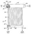
- FIG. 2is a side view of a solar receiver showing the paths traveled by the liquid and gas coolants according to the present invention.
- FIG. 3is a partial cutaway top view of the solar receiver showing the arrangement of the tube ends and fins in the gas cooled end of the heat pipes of FIG. 2 .
- FIG. 4is a side view of a heat pipe of the solar receiver of FIGS. 2 and 3.
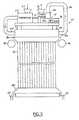
- FIG. 5is a side/block diagrammatic view of a solar receiver according to the present invention.
- FIG. 6is a block diagram of the solar collection process used by the solar receiver of FIG. 5 .
- a solar receiver system 10having a solar receiver 12 that receives sun ray 14 reflected from a heliostat 16 from sun 18 .
- Receiver 12is positioned on top of a tower 20 .
- several heliostats 20may be positioned around tower 20 to direct sun rays 14 at receiver 12 .
- the tower 20may be various heights depending on the particular location and system employed.
- the receiver 12is positioned adjacent to a liquid heat transfer device 20 and a power generation device 22 .
- the liquid heat transfer device 20has thermal storage 24 associated therewith for storing thermal energy from receiver 12 as will be further described below.
- Solar receiver 12includes a plurality of heat pipes 26 .
- the heat pipes 26are arranged generally in parallel and positioned about a cylinder.
- the heat pipesform the axially extending wall around the cylinder forming the solar receiver 12 .
- heat pipesmay be alternated in two rows having two different radii R 1 and R 2 from center C.
- Heat pipes 26have first ends 28 and second ends 30 .
- First ends 28form a first condenser 32 and second end 30 forms a second condenser 34 .
- the area between first end 28 and second end 30form an evaporator 36 therebetween.
- each heat pipe 26has each end sealed.
- the heat pipesare filled with a working fluid 38 that is preferably a liquid metal, although other liquids may be used.
- suitable heat pipe working fluidsare potassium, sodium and lithium.
- First ends 28 and second ends 30are used for convective heat transfer.
- fins 40may be formed thereon.
- the first endsare positioned within an air manifold 42 .
- Cool airenters the air manifold through an air inlet 44 and leaves the air manifold 42 through air outlet 46 .
- the second ends 30are preferably positioned within a liquid manifold 48 .
- Liquid manifold 48has a liquid inlet 50 and liquid outlet 52 . Liquid inlet 50 and liquid outlet 52 are fluidically coupled to thermal source 24 illustrated in FIG. 1 .
- each condenser end 28may be either separately or simultaneously cooled by air or liquid.
- supports 52are used to make the receiver 12 a rigid structure. Supports 52 strengthen the device and hold its shape.
- a thermal coating 54may be disposed on evaporator portion 36 of heat pipe 26 .
- Thermal coating 54is used to increase the amount of energy absorbed by and conducted into heat pipe 26 .
- a deployable radiation shield 56may be deployably coupled to solar receiver 12 .
- the radiation shield 56is thus unrolled to cover the evaporator portion 36 of the heat pipes 26 . This may be performed using an electric motor (not shown).
- Power generation device 22is illustrated in further detail.
- Power generation device 22may be positioned on a mounting platform 58 axially above and adjacent to air manifold 42 . This helps reduce the overall size of the solar receiver 12 .
- a compressor having a compressor air inlet 62is used to draw air into the system and route compressed air through a low temperature duct 64 to inlet 44 of air manifold 42 .
- Heated air leaving air manifold 46is routed through a high temperature duct 66 to a power turbine 68 .
- Power turbine 68is used to expand the air within duct 66 , converting the energy therein into mechanical energy.
- Low pressure and reduced temperature airis exhausted through turbine air outlet 70 .
- Power turbine 68has a first shaft 72 and a second shaft 74 which are rotated in response to the expansion of the heated air from high temperature duct 66 .
- the rotation of shaft 72turns a compressor which in turn compresses the air from compressor air inlet 62 .
- Shaft 74is coupled to gears 76 which in turn drive a generator 78 to generate electrical energy.
- Reflectors 80 , 82may be positioned respectively near first end 28 and second ends 30 of heat pipes 26 to reflect solar energy therefrom.
- Liquid manifold 48is shown thermally coupled to thermal storage unit 24 .
- a valve/pump 84may be positioned within the fluid lines 86 to control the flow of fluid therethrough.
- Compressor air inlet 62receives ambient air which is directed into compressor 60 .
- Compressed airis routed from compressor 60 through duct 64 to air inlet 44 of air manifold 42 .
- Heated high pressure air from air manifold 42is routed to power turbine 68 through high temperature and high pressure duct 66 .
- Power turbineexpands the air from high temperature and pressure duct 68 , rotating shaft 72 , 74 .
- Shaft 72turns compressor 60 to compress inlet air.
- Power turbine 68turns output shaft 74 to turn gears within gearbox 76 which in turn rotate a shaft 88 to turn generator 78 to generate electricity.
- Generatormay, for example, generate 60 Hz alternating current.
- the operation of the solar receivermay be divided into two temperature operating regions. At a high temperature when the sun is shining and thus sun rays 14 are directed by heliostat 20 to the receiver 12 , operates as follows: heated working fluid 38 within the heat pipes 26 heat liquid within liquid manifold 48 , the heat from which is stored in thermal storage 24 by the heated liquid transferred to the thermal storage unit.
- the first condenserheats air within the air manifold 42 which was compressed by compressor 60 .
- the compressed heated airoperates power turbine 68 which rotates a shaft to generate mechanical work therefrom.
- the shaftmay be coupled to a generator or other source to generate electric power therefrom.
- heated liquid stored in the thermal storage device 24is transferred to the liquid manifold 48 .
- the heated liquidheats the working fluid 38 at the second end 30 .
- the heatis transferred through the working fluid to the first end 28 which in turns heats air within the air manifold 42 .
- the heated air in air manifoldoperates the turbine 68 as described above.
- the valve/pump 84may be used to provide the liquid from the thermal storage to the liquid manifold 20 .
- the present inventionprovides a compact solar receiver.
- the shape of the solar receiverdepends on the shape of the solar field.
- an elongated rectangular solar receiver in a similar shape to a billboardmay also be used.
- the radiation shield 56when operating from the thermal storage 24 when the temperature is low, the radiation shield 56 may be used to prevent heat losses through the heat pipes 26 by insulating them. Thus, when the radiation shields 56 are lowered, they provide an insulating effect for the heat pipes 26 .
Landscapes
- Engineering & Computer Science (AREA)
- Chemical & Material Sciences (AREA)
- Combustion & Propulsion (AREA)
- Life Sciences & Earth Sciences (AREA)
- Sustainable Development (AREA)
- Sustainable Energy (AREA)
- Mechanical Engineering (AREA)
- General Engineering & Computer Science (AREA)
- Physics & Mathematics (AREA)
- Thermal Sciences (AREA)
- Engine Equipment That Uses Special Cycles (AREA)
- Photovoltaic Devices (AREA)
Abstract
Description
Claims (21)
Priority Applications (1)
| Application Number | Priority Date | Filing Date | Title |
|---|---|---|---|
| US10/315,485US6668555B1 (en) | 2002-12-09 | 2002-12-09 | Solar receiver-based power generation system |
Applications Claiming Priority (1)
| Application Number | Priority Date | Filing Date | Title |
|---|---|---|---|
| US10/315,485US6668555B1 (en) | 2002-12-09 | 2002-12-09 | Solar receiver-based power generation system |
Publications (1)
| Publication Number | Publication Date |
|---|---|
| US6668555B1true US6668555B1 (en) | 2003-12-30 |
Family
ID=29735873
Family Applications (1)
| Application Number | Title | Priority Date | Filing Date |
|---|---|---|---|
| US10/315,485Expired - LifetimeUS6668555B1 (en) | 2002-12-09 | 2002-12-09 | Solar receiver-based power generation system |
Country Status (1)
| Country | Link |
|---|---|
| US (1) | US6668555B1 (en) |
Cited By (55)
| Publication number | Priority date | Publication date | Assignee | Title |
|---|---|---|---|---|
| US20040244376A1 (en)* | 2003-06-03 | 2004-12-09 | Litwin Robert Z. | Systems and methods for generating electrical power from solar energy |
| US20050198959A1 (en)* | 2004-03-15 | 2005-09-15 | Frank Schubert | Electric generation facility and method employing solar technology |
| US20060225730A1 (en)* | 2005-04-07 | 2006-10-12 | Arnold Anderson | Radiant Energy Collector |
| US20070234749A1 (en)* | 2006-04-05 | 2007-10-11 | Enis Ben M | Thermal energy storage system using compressed air energy and/or chilled water from desalination processes |
| US20080078378A1 (en)* | 2006-07-25 | 2008-04-03 | Yanong Zhu | Method and apparatus of solar central receiver with boiler and super-heater |
| US20080289334A1 (en)* | 2007-05-08 | 2008-11-27 | Matt Orosz | Solar collection and conversion system and methods and apparatus for control thereof |
| US20090072632A1 (en)* | 2007-09-14 | 2009-03-19 | Kay Thomas P | Magnetohydrodynamic Engergy Conversion Device Using Solar Radiation as an Energy Source |
| WO2009015388A3 (en)* | 2007-07-26 | 2009-08-20 | Brightsource Energy Inc | Solar receiver |
| US20090212570A1 (en)* | 2008-02-23 | 2009-08-27 | Le John O | Hybrid solar thermal chimney |
| US20090255527A1 (en)* | 2008-04-10 | 2009-10-15 | Cheryl Glazer | Solar-powered system and method for providing utilities |
| US20090308072A1 (en)* | 2008-06-11 | 2009-12-17 | Kay Thomas P | Solar Energy Conversion Using Brayton Cycle System |
| US20100101621A1 (en)* | 2008-10-28 | 2010-04-29 | Jun Xu | Solar powered generating apparatus and methods |
| CN101033892B (en)* | 2007-04-16 | 2010-05-19 | 中国科学院电工研究所 | High-temperature heat absorber for a solar tower thermal power station |
| US20100212656A1 (en)* | 2008-07-10 | 2010-08-26 | Infinia Corporation | Thermal energy storage device |
| US20100223925A1 (en)* | 2009-03-06 | 2010-09-09 | Mitsubishi Heavy Industries, Ltd. | Solar thermal receiver and solar thermal power generation facility |
| CN101886846A (en)* | 2010-06-25 | 2010-11-17 | 河海大学 | Measurement and control system and performance, temperature prediction and protection method of solar air heat absorber |
| CN101936608A (en)* | 2010-09-28 | 2011-01-05 | 中国科学院电工研究所 | A two-stage heat pipe solar air heater |
| CN101307956B (en)* | 2008-06-24 | 2011-02-09 | 中国科学院电工研究所 | A kind of pressurized air heat absorber for solar thermal power station |
| US20110079217A1 (en)* | 2009-02-12 | 2011-04-07 | Babcock Power Services, Inc. | Piping, header, and tubing arrangements for solar boilers |
| WO2011047164A1 (en)* | 2009-10-14 | 2011-04-21 | Jeffrey Lee | Solar energy collector system and method |
| US20110214406A1 (en)* | 2010-03-08 | 2011-09-08 | Tma Power, Llc | Microturbine sun tracker |
| WO2011151488A1 (en) | 2010-06-02 | 2011-12-08 | Abengoa Solar New Technologies, S.A. | Concave receiver for stirling dish and manufacturing method therefor |
| WO2012001183A1 (en) | 2010-06-02 | 2012-01-05 | Abengoa Solar New Technologies, S.A. | Coil solar receiver for a stirling disk and method for manufacturing same |
| US20120132403A1 (en)* | 2009-06-19 | 2012-05-31 | Abengoa Solar New Technologies, S.A. | Method for the natural-draught cooling of a solar concentration plant |
| US8316843B2 (en) | 2009-02-12 | 2012-11-27 | Babcock Power Services Inc. | Arrangement of tubing in solar boiler panels |
| US8356591B2 (en) | 2009-02-12 | 2013-01-22 | Babcock Power Services, Inc. | Corner structure for walls of panels in solar boilers |
| US8378280B2 (en) | 2007-06-06 | 2013-02-19 | Areva Solar, Inc. | Integrated solar energy receiver-storage unit |
| US8397710B2 (en) | 2009-02-12 | 2013-03-19 | Babcock Power Services Inc. | Solar receiver panels |
| US20130074826A1 (en)* | 2011-09-26 | 2013-03-28 | The Cyprus Institute | Integrated solar receiver - thermal storage system |
| CN103017366A (en)* | 2012-12-13 | 2013-04-03 | 东南大学 | Partitioned solar high-temperature heat pipe central receiver |
| US8430092B2 (en) | 2009-02-12 | 2013-04-30 | Babcock Power Services, Inc. | Panel support system for solar boilers |
| WO2013074821A1 (en)* | 2011-11-16 | 2013-05-23 | Babcock & Wilcox Power Generation Group, Inc. | High efficiency solar receiver |
| CN103148602A (en)* | 2013-02-01 | 2013-06-12 | 中国科学院电工研究所 | Solid particle accumulation bed-type air heat absorber for solar thermal power station |
| US8517008B2 (en) | 2009-02-12 | 2013-08-27 | Babcock Power Services, Inc. | Modular solar receiver panels and solar boilers with modular receiver panels |
| US8573196B2 (en) | 2010-08-05 | 2013-11-05 | Babcock Power Services, Inc. | Startup/shutdown systems and methods for a solar thermal power generating facility |
| US20140102095A1 (en)* | 2012-10-17 | 2014-04-17 | Korea Institute Of Geoscience And Mineral Resources | Geothermal power generation system and method using heat exchange between working gas and molten salt |
| US8739512B2 (en) | 2007-06-06 | 2014-06-03 | Areva Solar, Inc. | Combined cycle power plant |
| CN103867411A (en)* | 2014-04-04 | 2014-06-18 | 华北电力大学 | Method and device for hierarchical type solar energy and gas turbine combined cycle complementation |
| US8807128B2 (en) | 2007-08-27 | 2014-08-19 | Areva Solar, Inc. | Linear fresnel solar arrays |
| US8823195B2 (en) | 2012-04-03 | 2014-09-02 | Mark Robert John LEGACY | Hydro electric energy generation and storage structure |
| US20140298807A1 (en)* | 2011-12-18 | 2014-10-09 | Jonas Villarrubia Ruiz | Solar collector with solar turbine or turbocharger |
| US20140305124A1 (en)* | 2011-11-25 | 2014-10-16 | Mitsubishi Heavy Industries, Ltd. | Solar heat receiver and solar heat power generation device |
| US8893714B2 (en) | 2009-02-12 | 2014-11-25 | Babcock Power Services, Inc. | Expansion joints for panels in solar boilers |
| US9022020B2 (en) | 2007-08-27 | 2015-05-05 | Areva Solar, Inc. | Linear Fresnel solar arrays and drives therefor |
| US9038624B2 (en) | 2011-06-08 | 2015-05-26 | Babcock Power Services, Inc. | Solar boiler tube panel supports |
| US20150192112A1 (en)* | 2012-09-25 | 2015-07-09 | Siemens Aktiengesellschaft | Arrangement for concentrated solar power energy conversion |
| US9134043B2 (en) | 2009-02-12 | 2015-09-15 | Babcock Power Services Inc. | Heat transfer passes for solar boilers |
| US9151518B2 (en) | 2009-06-03 | 2015-10-06 | Abengoa Solar New Technologies, S.A. | Solar concentrator plant using natural-draught tower technology and operating method |
| US9163857B2 (en) | 2009-02-12 | 2015-10-20 | Babcock Power Services, Inc. | Spray stations for temperature control in solar boilers |
| WO2016098107A3 (en)* | 2014-12-14 | 2016-08-04 | Leos Space Systems Ltd. | System for enhancing solar panel efficiency and methods of using same |
| EP2322796A3 (en)* | 2009-11-16 | 2016-11-30 | General Electric Company | Systems and apparatus relating to solar-thermal power generation |
| US9726155B2 (en) | 2010-09-16 | 2017-08-08 | Wilson Solarpower Corporation | Concentrated solar power generation using solar receivers |
| US10876521B2 (en) | 2012-03-21 | 2020-12-29 | 247Solar Inc. | Multi-thermal storage unit systems, fluid flow control devices, and low pressure solar receivers for solar power systems, and related components and uses thereof |
| WO2021189416A1 (en)* | 2020-03-27 | 2021-09-30 | 林郅燊 | Heat pipe-type electricity-generating water heater |
| US12305888B2 (en) | 2020-04-02 | 2025-05-20 | 247Solar Inc. | Concentrated solar energy collection, thermal storage, and power generation systems and methods with optional supplemental fuel production |
Citations (5)
| Publication number | Priority date | Publication date | Assignee | Title |
|---|---|---|---|---|
| US4262483A (en)* | 1978-07-20 | 1981-04-21 | Degeus Arie M | Rotating heat pipe solar power generator |
| US4598695A (en)* | 1985-05-30 | 1986-07-08 | Sundstrand Corporation | Solar boiler or energy storage apparatus |
| US4947825A (en)* | 1989-09-11 | 1990-08-14 | Rockwell International Corporation | Solar concentrator - radiator assembly |
| US5113659A (en)* | 1991-03-27 | 1992-05-19 | The United States Of America As Represented By The Administrator Of The National Aeronautics And Space Administration | Solar thermal energy receiver |
| US6487859B2 (en)* | 2000-08-03 | 2002-12-03 | Midwest Research Institute | Dish/stirling hybrid-receiver |
- 2002
- 2002-12-09USUS10/315,485patent/US6668555B1/ennot_activeExpired - Lifetime
Patent Citations (5)
| Publication number | Priority date | Publication date | Assignee | Title |
|---|---|---|---|---|
| US4262483A (en)* | 1978-07-20 | 1981-04-21 | Degeus Arie M | Rotating heat pipe solar power generator |
| US4598695A (en)* | 1985-05-30 | 1986-07-08 | Sundstrand Corporation | Solar boiler or energy storage apparatus |
| US4947825A (en)* | 1989-09-11 | 1990-08-14 | Rockwell International Corporation | Solar concentrator - radiator assembly |
| US5113659A (en)* | 1991-03-27 | 1992-05-19 | The United States Of America As Represented By The Administrator Of The National Aeronautics And Space Administration | Solar thermal energy receiver |
| US6487859B2 (en)* | 2000-08-03 | 2002-12-03 | Midwest Research Institute | Dish/stirling hybrid-receiver |
Non-Patent Citations (2)
| Title |
|---|
| Office of Energy Efficiency and Renewable Energy Network (EREN); U.S. Department of Energy, Concentrating Solar Power (CSP) Program; http://www.eren.doe.gov/csp/pdfs/solar_dish.pdf; "Solar Dish Engine". |
| Office of Energy Efficiency and Renewable Energy, Department of Energy, Consumer Energy Information: EREC Reference Briefs; http://www/eren.doe.gov/consumerinfo/rebriefs/ba9.html; "Heat Engines". |
Cited By (82)
| Publication number | Priority date | Publication date | Assignee | Title |
|---|---|---|---|---|
| US6957536B2 (en)* | 2003-06-03 | 2005-10-25 | The Boeing Company | Systems and methods for generating electrical power from solar energy |
| US20040244376A1 (en)* | 2003-06-03 | 2004-12-09 | Litwin Robert Z. | Systems and methods for generating electrical power from solar energy |
| WO2005089468A3 (en)* | 2004-03-15 | 2009-04-09 | Powerstreams Inc | Electric generation facility and method employing solar technology |
| US20050198959A1 (en)* | 2004-03-15 | 2005-09-15 | Frank Schubert | Electric generation facility and method employing solar technology |
| US7171812B2 (en)* | 2004-03-15 | 2007-02-06 | Powerstreams, Inc. | Electric generation facility and method employing solar technology |
| US20060225730A1 (en)* | 2005-04-07 | 2006-10-12 | Arnold Anderson | Radiant Energy Collector |
| WO2006110739A3 (en)* | 2005-04-07 | 2007-09-27 | Solar Power Solutions Inc | Radiant energy collector |
| US7763840B2 (en) | 2005-04-07 | 2010-07-27 | Solar Power Solutions, Inc. | Radiant energy collector |
| US20070234749A1 (en)* | 2006-04-05 | 2007-10-11 | Enis Ben M | Thermal energy storage system using compressed air energy and/or chilled water from desalination processes |
| US7856843B2 (en)* | 2006-04-05 | 2010-12-28 | Enis Ben M | Thermal energy storage system using compressed air energy and/or chilled water from desalination processes |
| US20080078378A1 (en)* | 2006-07-25 | 2008-04-03 | Yanong Zhu | Method and apparatus of solar central receiver with boiler and super-heater |
| CN101033892B (en)* | 2007-04-16 | 2010-05-19 | 中国科学院电工研究所 | High-temperature heat absorber for a solar tower thermal power station |
| US8132409B2 (en) | 2007-05-08 | 2012-03-13 | Solar Turbine Group, International | Solar collection and conversion system and methods and apparatus for control thereof |
| US20080289334A1 (en)* | 2007-05-08 | 2008-11-27 | Matt Orosz | Solar collection and conversion system and methods and apparatus for control thereof |
| US8378280B2 (en) | 2007-06-06 | 2013-02-19 | Areva Solar, Inc. | Integrated solar energy receiver-storage unit |
| US8739512B2 (en) | 2007-06-06 | 2014-06-03 | Areva Solar, Inc. | Combined cycle power plant |
| WO2009015388A3 (en)* | 2007-07-26 | 2009-08-20 | Brightsource Energy Inc | Solar receiver |
| US8490618B2 (en) | 2007-07-26 | 2013-07-23 | Brightsource Industries (Israel) Ltd. | Solar receiver |
| US9022020B2 (en) | 2007-08-27 | 2015-05-05 | Areva Solar, Inc. | Linear Fresnel solar arrays and drives therefor |
| US8807128B2 (en) | 2007-08-27 | 2014-08-19 | Areva Solar, Inc. | Linear fresnel solar arrays |
| US20090072632A1 (en)* | 2007-09-14 | 2009-03-19 | Kay Thomas P | Magnetohydrodynamic Engergy Conversion Device Using Solar Radiation as an Energy Source |
| US7982343B2 (en)* | 2007-09-14 | 2011-07-19 | Kay Thomas P | Magnetohydrodynamic engergy conversion device using solar radiation as an energy source |
| US7821151B2 (en)* | 2008-02-23 | 2010-10-26 | Le John O | Hybrid solar thermal chimney |
| US20090212570A1 (en)* | 2008-02-23 | 2009-08-27 | Le John O | Hybrid solar thermal chimney |
| US7845345B2 (en)* | 2008-04-10 | 2010-12-07 | Cheryl Glazer | Solar-powered system and method for providing utilities |
| US20090255527A1 (en)* | 2008-04-10 | 2009-10-15 | Cheryl Glazer | Solar-powered system and method for providing utilities |
| US20090308072A1 (en)* | 2008-06-11 | 2009-12-17 | Kay Thomas P | Solar Energy Conversion Using Brayton Cycle System |
| CN101307956B (en)* | 2008-06-24 | 2011-02-09 | 中国科学院电工研究所 | A kind of pressurized air heat absorber for solar thermal power station |
| US20100212656A1 (en)* | 2008-07-10 | 2010-08-26 | Infinia Corporation | Thermal energy storage device |
| US20100101621A1 (en)* | 2008-10-28 | 2010-04-29 | Jun Xu | Solar powered generating apparatus and methods |
| US8893714B2 (en) | 2009-02-12 | 2014-11-25 | Babcock Power Services, Inc. | Expansion joints for panels in solar boilers |
| US8397710B2 (en) | 2009-02-12 | 2013-03-19 | Babcock Power Services Inc. | Solar receiver panels |
| US8430092B2 (en) | 2009-02-12 | 2013-04-30 | Babcock Power Services, Inc. | Panel support system for solar boilers |
| US8733340B2 (en) | 2009-02-12 | 2014-05-27 | Babcock Power Services, Inc. | Arrangement of tubing in solar boiler panels |
| US20110079217A1 (en)* | 2009-02-12 | 2011-04-07 | Babcock Power Services, Inc. | Piping, header, and tubing arrangements for solar boilers |
| US9134043B2 (en) | 2009-02-12 | 2015-09-15 | Babcock Power Services Inc. | Heat transfer passes for solar boilers |
| US8517008B2 (en) | 2009-02-12 | 2013-08-27 | Babcock Power Services, Inc. | Modular solar receiver panels and solar boilers with modular receiver panels |
| US8316843B2 (en) | 2009-02-12 | 2012-11-27 | Babcock Power Services Inc. | Arrangement of tubing in solar boiler panels |
| US8356591B2 (en) | 2009-02-12 | 2013-01-22 | Babcock Power Services, Inc. | Corner structure for walls of panels in solar boilers |
| US9163857B2 (en) | 2009-02-12 | 2015-10-20 | Babcock Power Services, Inc. | Spray stations for temperature control in solar boilers |
| US20100223925A1 (en)* | 2009-03-06 | 2010-09-09 | Mitsubishi Heavy Industries, Ltd. | Solar thermal receiver and solar thermal power generation facility |
| US9151518B2 (en) | 2009-06-03 | 2015-10-06 | Abengoa Solar New Technologies, S.A. | Solar concentrator plant using natural-draught tower technology and operating method |
| US20120132403A1 (en)* | 2009-06-19 | 2012-05-31 | Abengoa Solar New Technologies, S.A. | Method for the natural-draught cooling of a solar concentration plant |
| US9086058B2 (en)* | 2009-06-19 | 2015-07-21 | Abengoa Solar New Technologies, S.A. | Method for the natural-draught cooling of a solar concentration plant |
| US20110114081A1 (en)* | 2009-10-14 | 2011-05-19 | Jeffrey Lee | Solar collector system |
| WO2011047164A1 (en)* | 2009-10-14 | 2011-04-21 | Jeffrey Lee | Solar energy collector system and method |
| US8967136B2 (en) | 2009-10-14 | 2015-03-03 | Jeffrey Lee | Solar collector system |
| CN102648381A (en)* | 2009-10-14 | 2012-08-22 | 杰弗里.李 | Solar collector systems and methods |
| EP2322796A3 (en)* | 2009-11-16 | 2016-11-30 | General Electric Company | Systems and apparatus relating to solar-thermal power generation |
| US8671685B2 (en) | 2010-03-08 | 2014-03-18 | Tma Power, Llc | Microturbine Sun Tracker |
| US20110214406A1 (en)* | 2010-03-08 | 2011-09-08 | Tma Power, Llc | Microturbine sun tracker |
| US9080790B2 (en) | 2010-06-02 | 2015-07-14 | Abengoa Solar New Technologies, S.A. | Concave receiver for stirling dish and method for manufacturing the same |
| WO2012001183A1 (en) | 2010-06-02 | 2012-01-05 | Abengoa Solar New Technologies, S.A. | Coil solar receiver for a stirling disk and method for manufacturing same |
| WO2011151488A1 (en) | 2010-06-02 | 2011-12-08 | Abengoa Solar New Technologies, S.A. | Concave receiver for stirling dish and manufacturing method therefor |
| CN101886846A (en)* | 2010-06-25 | 2010-11-17 | 河海大学 | Measurement and control system and performance, temperature prediction and protection method of solar air heat absorber |
| CN101886846B (en)* | 2010-06-25 | 2012-09-26 | 河海大学 | Solar air heat absorber measurement and control system and performance and temperature prediction and protection method |
| US9347685B2 (en) | 2010-08-05 | 2016-05-24 | Babcock Power Services Inc. | Startup systems and methods for solar boilers |
| US8573196B2 (en) | 2010-08-05 | 2013-11-05 | Babcock Power Services, Inc. | Startup/shutdown systems and methods for a solar thermal power generating facility |
| US9726155B2 (en) | 2010-09-16 | 2017-08-08 | Wilson Solarpower Corporation | Concentrated solar power generation using solar receivers |
| US10280903B2 (en) | 2010-09-16 | 2019-05-07 | Wilson 247Solar, Inc. | Concentrated solar power generation using solar receivers |
| US11242843B2 (en) | 2010-09-16 | 2022-02-08 | 247Solar Inc. | Concentrated solar power generation using solar receivers |
| CN101936608A (en)* | 2010-09-28 | 2011-01-05 | 中国科学院电工研究所 | A two-stage heat pipe solar air heater |
| US9038624B2 (en) | 2011-06-08 | 2015-05-26 | Babcock Power Services, Inc. | Solar boiler tube panel supports |
| US20130074826A1 (en)* | 2011-09-26 | 2013-03-28 | The Cyprus Institute | Integrated solar receiver - thermal storage system |
| WO2013074821A1 (en)* | 2011-11-16 | 2013-05-23 | Babcock & Wilcox Power Generation Group, Inc. | High efficiency solar receiver |
| US20140305124A1 (en)* | 2011-11-25 | 2014-10-16 | Mitsubishi Heavy Industries, Ltd. | Solar heat receiver and solar heat power generation device |
| US10060418B2 (en)* | 2011-11-25 | 2018-08-28 | Mitsubishi Heavy Industries, Ltd. | Solar heat receiver and solar heat power generation device |
| US20140298807A1 (en)* | 2011-12-18 | 2014-10-09 | Jonas Villarrubia Ruiz | Solar collector with solar turbine or turbocharger |
| US10961987B2 (en)* | 2011-12-18 | 2021-03-30 | Jonas Villarrubia Ruiz | Solar collector and turbine arrangement |
| US10876521B2 (en) | 2012-03-21 | 2020-12-29 | 247Solar Inc. | Multi-thermal storage unit systems, fluid flow control devices, and low pressure solar receivers for solar power systems, and related components and uses thereof |
| US8823195B2 (en) | 2012-04-03 | 2014-09-02 | Mark Robert John LEGACY | Hydro electric energy generation and storage structure |
| US20150192112A1 (en)* | 2012-09-25 | 2015-07-09 | Siemens Aktiengesellschaft | Arrangement for concentrated solar power energy conversion |
| US9624912B2 (en)* | 2012-10-17 | 2017-04-18 | Korea Institute Of Geoscience And Mineral Resources | Geothermal power generation system and method using heat exchange between working gas and molten salt |
| US20140102095A1 (en)* | 2012-10-17 | 2014-04-17 | Korea Institute Of Geoscience And Mineral Resources | Geothermal power generation system and method using heat exchange between working gas and molten salt |
| CN103017366B (en)* | 2012-12-13 | 2014-06-11 | 东南大学 | Partitioned solar high-temperature heat pipe central receiver |
| CN103017366A (en)* | 2012-12-13 | 2013-04-03 | 东南大学 | Partitioned solar high-temperature heat pipe central receiver |
| CN103148602A (en)* | 2013-02-01 | 2013-06-12 | 中国科学院电工研究所 | Solid particle accumulation bed-type air heat absorber for solar thermal power station |
| CN103867411B (en)* | 2014-04-04 | 2016-08-17 | 华北电力大学 | The method and device that hierarchical solar is complementary with Gas Turbine Combined-cycle |
| CN103867411A (en)* | 2014-04-04 | 2014-06-18 | 华北电力大学 | Method and device for hierarchical type solar energy and gas turbine combined cycle complementation |
| WO2016098107A3 (en)* | 2014-12-14 | 2016-08-04 | Leos Space Systems Ltd. | System for enhancing solar panel efficiency and methods of using same |
| WO2021189416A1 (en)* | 2020-03-27 | 2021-09-30 | 林郅燊 | Heat pipe-type electricity-generating water heater |
| US12305888B2 (en) | 2020-04-02 | 2025-05-20 | 247Solar Inc. | Concentrated solar energy collection, thermal storage, and power generation systems and methods with optional supplemental fuel production |
Similar Documents
| Publication | Publication Date | Title |
|---|---|---|
| US6668555B1 (en) | Solar receiver-based power generation system | |
| US7964787B2 (en) | Hybrid solar power generator | |
| US6957536B2 (en) | Systems and methods for generating electrical power from solar energy | |
| US5899071A (en) | Adaptive thermal controller for heat engines | |
| US7340899B1 (en) | Solar power generation system | |
| US8087245B2 (en) | Solar concentrator plant | |
| US9027347B2 (en) | Solar collector, and an electrical energy generation plant including such solar collectors | |
| CN102062066A (en) | Systems and apparatus relating to solar-thermal power generation | |
| EP2601392A2 (en) | Solar tower with integrated gas turbine | |
| CN101504199A (en) | Low cost solar tracing and novel thermal circulation method | |
| US20120096830A1 (en) | Turbine and method thereof | |
| CA2736418A1 (en) | A low temperature solar power system | |
| WO2015077235A1 (en) | Concentrated solar power systems and methods utilizing cold thermal energy storage | |
| Andraka et al. | Solar heat pipe testing of the Stirling thermal motors 4-120 Stirling engine | |
| US20180128519A1 (en) | Solar Turbo Pump - Hybrid Heating Air-Conditioning and Method of Operation | |
| CN115013156A (en) | A near-field thermal photovoltaic power generation device for waste heat recovery of aero-engine | |
| JP2008057823A (en) | Solar heat collector and solar heat utilization apparatus using the same | |
| US9121392B2 (en) | Geothermal power generation system and method using heat exchange between working fluid and molten salt | |
| US20120227425A1 (en) | Solar turbo pump - hybrid heating-air conditioning and method of operation | |
| EP3779166B1 (en) | Thermal and electrical power transformer | |
| CN220353987U (en) | Photo-thermal energy storage power generation system | |
| JP2002031035A (en) | Solar power generator | |
| EP3338034A1 (en) | Solar turbo pump hybrid heating air conditioning and method of operation | |
| JP2001248539A (en) | Displacement type solar low temperature difference engine system | |
| US4081965A (en) | Solar operated turbine power generator |
Legal Events
| Date | Code | Title | Description |
|---|---|---|---|
| AS | Assignment | Owner name:BOEING COMPANY, THE, ILLINOIS Free format text:ASSIGNMENT OF ASSIGNORS INTEREST;ASSIGNOR:MORIARTY, MICHAEL P.;REEL/FRAME:013569/0062 Effective date:20021204 | |
| STCF | Information on status: patent grant | Free format text:PATENTED CASE | |
| AS | Assignment | Owner name:UNITED TECHNOLOGIES CORPORATION,CONNECTICUT Free format text:ASSIGNMENT OF ASSIGNORS INTEREST;ASSIGNOR:BOEING COMPANY AND BOEING MANAGEMENT COMPANY, THE;REEL/FRAME:017681/0537 Effective date:20050802 Owner name:UNITED TECHNOLOGIES CORPORATION, CONNECTICUT Free format text:ASSIGNMENT OF ASSIGNORS INTEREST;ASSIGNOR:BOEING COMPANY AND BOEING MANAGEMENT COMPANY, THE;REEL/FRAME:017681/0537 Effective date:20050802 | |
| AS | Assignment | Owner name:UNITED TECHNOLOGIES CORPORATION,CONNECTICUT Free format text:ASSIGNMENT OF ASSIGNORS INTEREST;ASSIGNOR:BOEING C OMPANY AND BOEING MANAGEMENT COMPANY, THE;REEL/FRAME:017882/0126 Effective date:20050802 Owner name:UNITED TECHNOLOGIES CORPORATION, CONNECTICUT Free format text:ASSIGNMENT OF ASSIGNORS INTEREST;ASSIGNOR:BOEING C OMPANY AND BOEING MANAGEMENT COMPANY, THE;REEL/FRAME:017882/0126 Effective date:20050802 | |
| FPAY | Fee payment | Year of fee payment:4 | |
| FPAY | Fee payment | Year of fee payment:8 | |
| AS | Assignment | Owner name:RUBY ACQUISITION ENTERPRISES CO., CALIFORNIA Free format text:CORRECTIVE ASSIGNMENT TO CORRECT THE ASSIGNEE'S NAME ON ORIGINAL COVER SHEET PREVIOUSLY RECORDED ON REEL 017882 FRAME 0126. ASSIGNOR(S) HEREBY CONFIRMS THE ASSIGNEE WAS INCORRECTLY RECORDED AS "UNITED TECHNOLOGIES CORPORATION". ASSIGNEE SHOULD BE "RUBY ACQUISITION ENTERPRISES CO.";ASSIGNOR:THE BOEING COMPANY AND BOEING MANAGEMENT COMPANY;REEL/FRAME:030592/0954 Effective date:20050802 Owner name:PRATT & WHITNEY ROCKETDYNE, INC., CALIFORNIA Free format text:CHANGE OF NAME;ASSIGNOR:RUBY ACQUISITION ENTERPRISES CO.;REEL/FRAME:030593/0055 Effective date:20050802 | |
| AS | Assignment | Owner name:WELLS FARGO BANK, NATIONAL ASSOCIATION, NORTH CARO Free format text:SECURITY AGREEMENT;ASSIGNOR:PRATT & WHITNEY ROCKETDYNE, INC.;REEL/FRAME:030628/0408 Effective date:20130614 | |
| AS | Assignment | Owner name:U.S. BANK NATIONAL ASSOCIATION, CALIFORNIA Free format text:SECURITY AGREEMENT;ASSIGNOR:PRATT & WHITNEY ROCKETDYNE, INC.;REEL/FRAME:030656/0615 Effective date:20130614 | |
| AS | Assignment | Owner name:AEROJET ROCKETDYNE OF DE, INC., CALIFORNIA Free format text:CHANGE OF NAME;ASSIGNOR:PRATT & WHITNEY ROCKETDYNE, INC.;REEL/FRAME:032845/0909 Effective date:20130617 | |
| AS | Assignment | Owner name:SOLARRESERVE TECHNOLOGY, LLC, CALIFORNIA Free format text:ASSIGNMENT OF ASSIGNORS INTEREST;ASSIGNOR:AEROJET ROCKETDYNE OF DE;REEL/FRAME:034530/0978 Effective date:20141009 | |
| FPAY | Fee payment | Year of fee payment:12 | |
| AS | Assignment | Owner name:AEROJET ROCKETDYNE OF DE, INC., CALIFORNIA Free format text:RELEASE BY SECURED PARTY;ASSIGNOR:U.S. BANK NATIONAL ASSOCIATION;REEL/FRAME:036666/0103 Effective date:20141021 | |
| AS | Assignment | Owner name:AEROJET ROCKETDYNE OF DE, INC. (F/K/A PRATT & WHIT Free format text:RELEASE BY SECURED PARTY;ASSIGNOR:U.S. BANK NATIONAL ASSOCIATION;REEL/FRAME:039597/0890 Effective date:20160715 |