US6668466B1 - Highly accurate articulated coordinate measuring machine - Google Patents
Highly accurate articulated coordinate measuring machineDownload PDFInfo
- Publication number
- US6668466B1 US6668466B1US09/692,028US69202800AUS6668466B1US 6668466 B1US6668466 B1US 6668466B1US 69202800 AUS69202800 AUS 69202800AUS 6668466 B1US6668466 B1US 6668466B1
- Authority
- US
- United States
- Prior art keywords
- rotation
- axis
- encoder wheel
- encoder
- rigidly attached
- Prior art date
- Legal status (The legal status is an assumption and is not a legal conclusion. Google has not performed a legal analysis and makes no representation as to the accuracy of the status listed.)
- Expired - Lifetime, expires
Links
- 239000000523sampleSubstances0.000claimsabstractdescription219
- 230000033001locomotionEffects0.000claimsabstractdescription36
- 238000012545processingMethods0.000claimsabstractdescription34
- 238000003754machiningMethods0.000claimsdescription32
- 238000000034methodMethods0.000claimsdescription29
- 239000000463materialSubstances0.000claimsdescription18
- 230000000712assemblyEffects0.000claimsdescription16
- 238000000429assemblyMethods0.000claimsdescription16
- 230000003287optical effectEffects0.000claimsdescription13
- 230000005291magnetic effectEffects0.000claimsdescription11
- 238000004519manufacturing processMethods0.000claimsdescription9
- 230000035515penetrationEffects0.000claimsdescription7
- 230000001939inductive effectEffects0.000claimsdescription6
- 230000008569processEffects0.000claimsdescription6
- 229920000049Carbon (fiber)Polymers0.000claimsdescription5
- 239000004917carbon fiberSubstances0.000claimsdescription5
- 239000002131composite materialSubstances0.000claimsdescription5
- 229910001092metal group alloyInorganic materials0.000claimsdescription5
- VNWKTOKETHGBQD-UHFFFAOYSA-NmethaneChemical compoundCVNWKTOKETHGBQD-UHFFFAOYSA-N0.000claimsdescription5
- 229910001374InvarInorganic materials0.000claimsdescription4
- PNEYBMLMFCGWSK-UHFFFAOYSA-Naluminium oxideInorganic materials[O-2].[O-2].[O-2].[Al+3].[Al+3]PNEYBMLMFCGWSK-UHFFFAOYSA-N0.000claimsdescription4
- 229910000833kovarInorganic materials0.000claimsdescription4
- 239000011159matrix materialSubstances0.000claimsdescription4
- 229910052751metalInorganic materials0.000claimsdescription4
- 239000002184metalSubstances0.000claimsdescription4
- 230000008878couplingEffects0.000claimsdescription3
- 238000010168coupling processMethods0.000claimsdescription3
- 238000005859coupling reactionMethods0.000claimsdescription3
- 238000005553drillingMethods0.000claimsdescription3
- 238000006073displacement reactionMethods0.000claimsdescription2
- 239000012777electrically insulating materialSubstances0.000claimsdescription2
- 230000001681protective effectEffects0.000claimsdescription2
- ATJFFYVFTNAWJD-UHFFFAOYSA-NTinChemical compound[Sn]ATJFFYVFTNAWJD-UHFFFAOYSA-N0.000claims2
- 238000003801millingMethods0.000description22
- 238000007689inspectionMethods0.000description11
- 230000001965increasing effectEffects0.000description9
- 238000005520cutting processMethods0.000description8
- 238000005259measurementMethods0.000description8
- 238000012937correctionMethods0.000description6
- 238000010586diagramMethods0.000description6
- 239000012636effectorSubstances0.000description6
- 239000004593EpoxySubstances0.000description5
- 238000013480data collectionMethods0.000description5
- 230000007246mechanismEffects0.000description5
- FGUUSXIOTUKUDN-IBGZPJMESA-NC1(=CC=CC=C1)N1C2=C(NC([C@H](C1)NC=1OC(=NN=1)C1=CC=CC=C1)=O)C=CC=C2Chemical compoundC1(=CC=CC=C1)N1C2=C(NC([C@H](C1)NC=1OC(=NN=1)C1=CC=CC=C1)=O)C=CC=C2FGUUSXIOTUKUDN-IBGZPJMESA-N0.000description4
- 238000007405data analysisMethods0.000description4
- 230000009466transformationEffects0.000description4
- 241000350052Daniellia ogeaSpecies0.000description3
- 238000003070Statistical process controlMethods0.000description3
- 238000013459approachMethods0.000description3
- 238000005452bendingMethods0.000description3
- 238000004891communicationMethods0.000description3
- 230000000694effectsEffects0.000description3
- 238000005516engineering processMethods0.000description3
- 238000011156evaluationMethods0.000description3
- 238000004886process controlMethods0.000description3
- 239000007787solidSubstances0.000description3
- 239000007921spraySubstances0.000description3
- OKTJSMMVPCPJKN-UHFFFAOYSA-NCarbonChemical compound[C]OKTJSMMVPCPJKN-UHFFFAOYSA-N0.000description2
- 241000321453Paranthias colonusSpecies0.000description2
- MCMNRKCIXSYSNV-UHFFFAOYSA-NZirconium dioxideChemical compoundO=[Zr]=OMCMNRKCIXSYSNV-UHFFFAOYSA-N0.000description2
- 229910052799carbonInorganic materials0.000description2
- 239000000356contaminantSubstances0.000description2
- 239000000428dustSubstances0.000description2
- 238000002474experimental methodMethods0.000description2
- 230000006870functionEffects0.000description2
- 238000000227grindingMethods0.000description2
- 238000010438heat treatmentMethods0.000description2
- 238000002406microsurgeryMethods0.000description2
- 238000000926separation methodMethods0.000description2
- 238000000844transformationMethods0.000description2
- 238000013519translationMethods0.000description2
- 229910000838Al alloyInorganic materials0.000description1
- 241000238631HexapodaSpecies0.000description1
- 229910052581Si3N4Inorganic materials0.000description1
- 238000002679ablationMethods0.000description1
- 230000001133accelerationEffects0.000description1
- 239000000853adhesiveSubstances0.000description1
- 230000001070adhesive effectEffects0.000description1
- 230000002411adverseEffects0.000description1
- 230000032683agingEffects0.000description1
- 229910052782aluminiumInorganic materials0.000description1
- XAGFODPZIPBFFR-UHFFFAOYSA-NaluminiumChemical compound[Al]XAGFODPZIPBFFR-UHFFFAOYSA-N0.000description1
- 230000008901benefitEffects0.000description1
- 230000005540biological transmissionEffects0.000description1
- 238000005219brazingMethods0.000description1
- 238000004364calculation methodMethods0.000description1
- 230000015556catabolic processEffects0.000description1
- 239000000919ceramicSubstances0.000description1
- 229910010293ceramic materialInorganic materials0.000description1
- 238000011109contaminationMethods0.000description1
- 238000001816coolingMethods0.000description1
- 239000012809cooling fluidSubstances0.000description1
- 239000002173cutting fluidSubstances0.000description1
- 230000007423decreaseEffects0.000description1
- 230000008021depositionEffects0.000description1
- 238000013461designMethods0.000description1
- 238000011161developmentMethods0.000description1
- 230000018109developmental processEffects0.000description1
- 238000009760electrical discharge machiningMethods0.000description1
- 230000002708enhancing effectEffects0.000description1
- 239000003733fiber-reinforced compositeSubstances0.000description1
- 239000012530fluidSubstances0.000description1
- 238000003780insertionMethods0.000description1
- 230000037431insertionEffects0.000description1
- 230000005055memory storageEffects0.000description1
- 238000012986modificationMethods0.000description1
- 230000004048modificationEffects0.000description1
- 239000003973paintSubstances0.000description1
- 229910002077partially stabilized zirconiaInorganic materials0.000description1
- 239000002245particleSubstances0.000description1
- 238000003825pressingMethods0.000description1
- 230000000750progressive effectEffects0.000description1
- 238000003908quality control methodMethods0.000description1
- 239000011208reinforced composite materialSubstances0.000description1
- 238000011160researchMethods0.000description1
- 230000000284resting effectEffects0.000description1
- 239000004576sandSubstances0.000description1
- 238000006748scratchingMethods0.000description1
- 230000002393scratching effectEffects0.000description1
- 229910010271silicon carbideInorganic materials0.000description1
- HBMJWWWQQXIZIP-UHFFFAOYSA-Nsilicon carbideChemical compound[Si+]#[C-]HBMJWWWQQXIZIP-UHFFFAOYSA-N0.000description1
- HQVNEWCFYHHQES-UHFFFAOYSA-Nsilicon nitrideChemical compoundN12[Si]34N5[Si]62N3[Si]51N64HQVNEWCFYHHQES-UHFFFAOYSA-N0.000description1
- 238000005476solderingMethods0.000description1
- 238000009987spinningMethods0.000description1
- 238000001356surgical procedureMethods0.000description1
- 238000012360testing methodMethods0.000description1
- 238000012549trainingMethods0.000description1
- 238000012546transferMethods0.000description1
Images


Classifications
- G—PHYSICS
- G01—MEASURING; TESTING
- G01B—MEASURING LENGTH, THICKNESS OR SIMILAR LINEAR DIMENSIONS; MEASURING ANGLES; MEASURING AREAS; MEASURING IRREGULARITIES OF SURFACES OR CONTOURS
- G01B5/00—Measuring arrangements characterised by the use of mechanical techniques
- G01B5/004—Measuring arrangements characterised by the use of mechanical techniques for measuring coordinates of points
- G01B5/008—Measuring arrangements characterised by the use of mechanical techniques for measuring coordinates of points using coordinate measuring machines
Definitions
- This inventionrelates generally to the field of precision machining, and more specifically to an articulated coordinate measuring machine (ACMM), system, and method for providing independent, real-time position feedback control during precision machining.
- ACMMarticulated coordinate measuring machine
- the position of a movable machine memberis determined indirectly by sensing motion at a large distance away from the actual point of operation.
- the linear motion of a slide for a worktableis derived indirectly from rotational motion of a motor and lead screw combination by using a angle encoder or resolver.
- Another exampleis the use of a linear scale located adjacent to a guideway.
- a laser interferometer or a series of calibrated, multiple-length gauge blockscan be used.
- a precision variable-length ball-baris recommended.
- three-dimensional positional performancee.g. volumetric
- the length of a fixed ball-barshould be measured in 20 different locations along the edges, face diagonals, and body diagonals of a cubical work zone.
- the number of positionscan increase to 30-35 positions.
- CMMcoordinate measuring machine
- Laser trackerscan provide non-contact, real-time measurement in three dimensions of a retroreflector sphere or cube mounted to a surface. These devices utilize a motorized, gimbal-mounted laser interferometer, which tracks the moving retroreflector (such as the SMX-4500 Laser Tracker manufactured by Spatial Metrix Corp., or a SMART310e Laser Tracker manufactured by Leica, Inc.).
- a laser retroreflectorcan not be practically mounted to an actual spinning drill bit or cutting tool. More importantly, if an object obstructs the laser beam, tracking can be lost. Operation must be paused to allow re-acquisition of the reflecting target mirror.
- the data collection system of the systemshould be capable of processing position measurements at a sufficiently high data rate, commensurate with providing real-time feedback to a rapidly moving machine member. The accuracy of such a system should be better than 10 microns, preferably better than 3 microns. Such a system should be easily mounted on, or near, existing machines with minimal structural modifications.
- the ACMM's probecould be automatically guided by the moving member through all extremes of the workspace. This could make the application of the ACMM simple and automatic; requiring little skill or training.
- Existing feedback systemsi.e. resolvers, encoders, linear scales, etc. could be used for the servo controls velocity feedback loop, while using the independent position feedback of a pivotally mounted CMM for the displacement feedback loop.
- Gantry or bridge-style fixed 3-axis orthogonal (e.g. Cartesian) CMM'sprovide outstanding accuracy (better than 0.0001 inches), but are typically very expensive and are not portable.
- Multi-axis, portable CMM'sare commercially available from Romer, Inc. of Carlsbad, Calif. and by Faro Technologies, Inc. of Lake Mary, Fla. However, their accuracy is limited to about 0.001-0.005 inches.
- These portable ACMM'shave six degrees-of-freedom (one rotation axis and one swivel axis at each of the three joints, linked by two support arms).
- Six degrees-of-freedom(DOF's) provides the ability to easily position the probe tip underneath and behind complex shapes, without having to reposition the base.
- the use of rotary jointsalso minimizes errors due to torques and bending moments.
- Precision rotary transducerse.g. angle encoders are mounted at each of the six joints.
- the measuring volumeis generally spherical, with the radius equal to the maximum reach of the linked arms, typically a 3-6 foot radius.
- the tubular support armsare typically made of a lightweight and stiff material, such as an aluminum alloy, or a carbon fiber composite.
- Use of an independent, in-process inspection toolcan save time, and eliminate potential errors in re-positioning the part when machining starts-up again.
- Some machine toolssuch as horizontal and vertical lathes, rotate the workpiece during machining.
- the workpiece geometryis axisymmetric, only 2 degrees-of-freedom are required (e.g. travel down the centerline, Z-axis, and radial extension, R-axis). Consequently, a highly accurate ACMM, mounted to, for example, the tail stock frame of a horizontal lathe, and would only need two independent axes of revolution to provide complete measurement for a lathe-type machine tool.
- a 2 DOF ACMMcould also be used for measuring the contour of a part in a flat, 2-D plane (e.g. X-Y plane).
- An ACMM with only 1 DOFcould be used for performance evaluation and calibration of gantry-style 3-axis orthogonal CMM's.
- Electro-Discharge Machining (EDM) of metal partsinvolves passing a high current through a wire or sinker electrode, and spark-eroding the workpiece. Due to the high voltages involved, it would be useful if a highly accurate ACMM could withstand high voltages without damage.
- a highly accurate ACMMshould remain a lightweight and portable tool. This allows a single metrology tool to periodically check and certify an entire shop floor having a multitude of equipment.
- the toolshould be easily mounted on a working surface on, or near, existing machines.
- the toolshould be capable of hands-off operation (e.g. unattended), after initial setup.
- One methodwould be to reduce the number of serially linked joints (e.g. from six down to three) because the total position error builds upon the individual position errors for each joint linked in series.
- Another method to improve the accuracy of ACMM'swould be to increase the accuracy of the angle encoder(s).
- One approachwould be to wrap a linear encoder tape with a fine line pitch (e.g. fine gradation of marks) around the outside circumference of a circular encoder wheel. As the diameter of the wheel increases, so does the circumference. The larger circumference generates a proportionally larger number of counts (e.g. count rate) sensed by a read head for the same angle of rotation, as compared to a wheel having a smaller diameter that is wrapped with an encoder tape having the same line pitch. Likewise, for the same number of line counts, a wheel having a larger diameter will rotate a smaller angle than a wheel having a smaller diameter. Consequently, the angular accuracy can be increased essentially without limit by increasing the diameter of a wheel that has a linear encoder tape wrapped around the wheel's circumference.
- Accuracy of the ACMMcould also be increased by (1) using materials with a low thermal expansion coefficient, (2) requiring very tight machining tolerances, (3) using high precision ball or roller bearings (e.g. ABEC grade 7-9 ball bearings), and (4) using highly accurate angle encoders (e.g. increasing from 81,000 counts per revolution to 230 million counts per revolution).
- these changesgenerally increase the overall cost of the ACMM.
- 3-D digitizing/tracing of surfaces and solid objectsinclude 3-D spatial interfacing with a computer (e.g. a 3-D mouse/joystick); 3-D sculpting via a master-slave arrangement; and remote surgery or micro-surgery via a master-slave arrangement.
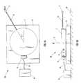
- FIG. 1Ashows a schematic top view of a first example an articulated coordinate measuring machine having a single degree of freedom, according to the present invention.
- FIG. 1Bshows a schematic side view of a first example of an articulated coordinate measuring machine having a single degree of freedom, according to the present invention.
- FIG. 1Cshows the geometric relationships between the two serially-linked arms, the three angles of revolution, and the probe point “P”, according to the present invention.
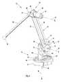
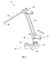
- FIG. 2shows a schematic isometric view of a second example of a highly accurate articulated coordinate measuring machine, according to the present invention.
- FIG. 3shows a first example of a magnetic kinematic mount for holding the base, according to the present invention.
- FIG. 4shows a schematic isometric view of a third example of a highly accurate articulated coordinate measuring machine, according to the present invention.
- FIG. 5 ashows a schematic isometric view of a third example of a highly accurate articulated coordinate measuring machine, according to the present invention.
- FIG. 5 bshows a schematic side view of a third example of a highly accurate articulated coordinate measuring machine, according to the present invention.
- FIG. 5 cshows a schematic top view of a third example of a highly accurate articulated coordinate measuring machine, according to the present invention.
- FIG. 5 dshows a schematic backside view of a third example of a highly accurate articulated coordinate measuring machine, according to the present invention.
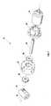
- FIG. 6shows a schematic cross-section view of a third example of a highly accurate articulated coordinate measuring machine, according to the present invention.
- FIG. 7shows a schematic isometric exploded view of a second example of the third revolute joint of the third example of a highly accurate articulated coordinate measuring machine, according to the present invention.
- FIG. 8shows a schematic view of a first example of probe tip body having multiple touch probes, according to the present invention.
- FIG. 9shows a schematic isometric view of a fourth example of a highly accurate articulated coordinate measuring machine, attached to a 3-axis CNC milling machine for providing position feedback control, or for calibration purposes, according to the present invention.
- FIG. 10shows a schematic isometric view of a fifth example of a highly accurate articulated coordinate measuring machine, attached to a 3-axis CNC milling machine for providing position feedback control, or for calibration purposes, with a flexible bag or bellows surrounding the ACMM, according to the present invention.
- FIG. 11shows a first example of a block diagram of the position data collection and analysis system, according to the present invention.
- FIG. 12shows a schematic isometric view of a sixth example of a highly accurate two-axis articulated coordinate measuring machine, attached to a horizontal CNC lathe for providing position feedback control, or for calibration purposes, according to the present invention.
- FIG. 13shows a schematic isometric view of a seventh example of a highly accurate articulated coordinate measuring machine, with an attached wand for using as a 3-D computer interface device, according to the present invention.
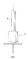
- FIG. 14shows a schematic isometric view of a eighth example of a highly accurate articulated coordinate measuring machine, according to the present invention.
- FIG. 15shows a schematic isometric view of a first example of a three-point pivot mount, according to the present invention.
- FIG. 16shows a schematic cross-section view of a first example of a three-point pivot mount, according to the present invention.
- FIG. 17shows a second example of a block diagram of the position data collection and analysis system, according to the present invention.
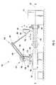
- FIG. 18shows a schematic side view of a ninth example of a metrology system for providing independent, real-time, position feedback control, according to the present invention.
- FIG. 19shows a schematic side view of a tenth example of a metrology system for independently evaluating the spatial positional performance of a movable machine member, according to the present invention.
- FIG. 20shows a schematic side view of a eleventh example of a metrology system for providing independent, real-time, position feedback control, according to the present invention, including a pair of 3-axis articulated coordinate measuring machines, attached on either side of the moving machine member.
- FIG. 21shows a schematic side view of a twelfth example of a metrology system for providing independent, real-time, position feedback control, according to the present invention, including a pair of 3-axis articulated coordinate measuring, machines, attached on either side of the movable machine member, which provides information about the position and orientation of the movable machine member.
- FIG. 22shows a schematic side view of a thirteenth example of a metrology system for using a movable machine member to perform automatic, machine-guided inspection of the spatial dimensions of a part, according to the present invention.
- FIG. 23shows a schematic block process diagram of a process for providing real-time feedback control, according to the present invention.
- FIG. 24Ashows a schematic top view of an example of an articulated coordinate measuring machine, according to the present invention.
- FIG. 24Bshows a schematic side view of an example of an articulated coordinate measuring machine, according to the present invention.
- FIG. 25Ashows a schematic top view of an example of an articulated coordinate measuring machine, according to the present invention.
- FIG. 25Bshows a schematic side view of an example of an articulated coordinate measuring machine, according to the present invention.
- FIG. 26shows a schematic side view of an example of an articulated coordinate measuring machine, according to the present invention.
- FIG. 27shows a schematic side view of an example of an articulated coordinate measuring machine, according to the present invention.
- FIG. 28shows a schematic side view of an example of an articulated coordinate measuring machine, according to the present invention.
- FIG. 29shows a schematic side view of an example of an articulated coordinate measuring machine, according to the present invention.
- FIG. 30shows a schematic side view of an example of an articulated coordinate measuring machine, according to the present invention.
- This inventionrelates generally to the field of precision machining, and more specifically to a system and method for providing independent, real-time position feedback control during precision machining.
- This inventionalso relates to an articulated coordinate measuring machine (ACMM).
- the ACMMis kinematically mounted to a working surface (e.g. worktable or frame).
- the ACMM's probe tipcan be physically attached to a movable machine member (e.g. a machine tool holder, or end effector of a robotic arm) to provide independent, real-time measurement of the member's position in one, two, or three-dimensional Cartesian space.
- the true measured positione.g.
- An ACMM with three degrees-of-freedomcan be described as a 3D Ball BarTM.
- FIGS. 1A and 1Bshow a schematic top view and side view, respectively, of a first example of an articulated coordinate measuring machine (ACMM) 10 having at least a single degree of freedom, according to the present invention.
- ACMM 10comprises a circular encoder wheel 1 , having an axis of rotation 2 .
- a plurality of marks 3are disposed around at least a portion of the circumference of the encoder wheel 1 .
- the markscan be lines, circles, oval, or other shapes.
- the markscan be uniformly or non-uniformly spaced apart.
- the linescan be spaced 20 microns apart. Non-uniformly spaced marks can provide the ability to determine the absolute angular position.
- the plurality of marks 3can be ruled directly onto the surface of the circumference of encoder wheel 1 . Ruling of marks can include precision machining or scratching of lines, deposition of lines via micro-lithographic techniques, or the creation of pits via laser beam ablation.
- ACMM 10further comprises bearing means 4 for supporting encoder wheel 1 while permitting free rotation of wheel 1 about axis of rotation 2 .
- Bearing means 4can be an air bearing, providing essentially frictionless support. Alternatively, bearing means 4 can include roller or ball bearings.
- a sensor 5is rigidly attached to bearing means 4 , and is used for detecting the motion of at least some of the marks 3 as the encoder wheel 1 rotates. Sensor 5 can comprise an optical detector, inductive detector, or magnetic detector.
- ACMM 10further comprises a probe arm 6 , having a proximal end rigidly attached to encoder wheel 1 , and having a distal end with a probe tip 7 attached thereto.
- ACMM 10further comprises a means (not shown) for kinematically constraining ACMM 10 to a working surface 8 .
- ACMM 10further comprises coordinate processing means 9 , operatively connected to sensor 5 , for converting the output of sensor 5 into a set of cylindrical coordinates representing the position of probe tip 7 relative to a reference cylindrical coordinate system (not shown). The set of cylindrical coordinates can represent the incremental position of probe tip 7 , relative to a previously known position.
- Processing means 9can be connected to sensor 5 with cable 11 .
- Wireless communication meanscan also be used to transmit information from sensor 5 to processing means 9 .
- Processing means 9can comprise a microprocessor with memory storage.
- Processing means 9can comprise means for converting the cylindrical coordinates into Cartesian (e.g. X,Y) coordinates.
- ACMM 10can comprise three serially-linked revolute joints, each having a respective angle of revolution.
- FIG. 1Cshows the geometric relationships between two serially-linked arms, three angles of revolution, and the probe point P according to the present invention.
- the two serially-linked armshave a length equal to L 1 and L 2 , respectively.
- the coordinates of probe point P, relative to the origin,correspond to (R, ⁇ , Z) in cylindrical coordinates.
- the same point Pcan also be described by the three angles of revolution, ⁇ 1 , ⁇ 2 , and ⁇ 3 ; combined with the two fixed link lengths, L 1 and L 2 .
- the axis of rotation for the first angle qcoincides with the Z-axis.
- the axis of rotation for the second angle, ⁇ 2passes through point “O”, is oriented perpendicular to the plane containing the points (O, A, P, B).
- the axis of rotation for the third angle, ⁇ 3passes through point “A”, and is oriented parallel to the axis of rotation for the second angle, ⁇ 2 , (as defined above). It is well known to those skilled in the art that any combination of the three independent angles of rotation, ⁇ 1 , ⁇ 2 , and ⁇ 3 , combined with the two fixed link lengths, L 1 and L 2 , can be translated by appropriate coordinate transformation matrices into cylindrical coordinates (R, ⁇ , Z), and from there to Cartesian coordinates (X, Y, Z) for point P.
- FIG. 2shows a schematic isometric view of a second example of a highly accurate articulated coordinate measuring machine (ACMM) 10 , according to the present invention.
- ACMM 10comprises a support base 12 , adapted to be rigidly fixed to a working surface (e.g. worktable or frame) 100 , that the three-dimensional spatial coordinates of the probe tip 30 can be measured relative to.
- base 12can be adapted to be fixed relative to working surface 100 (e.g. on a tripod or rigid stand, not shown).
- FIG. 2illustrates that the dimensions of a machined part 102 can be measured or probed by “touching” the surface of part 102 with probe tip 30 .
- the word “touching”broadly contemplates the use of non-contact probe tips, such as laser-probes and electrostatic probes. Not shown in FIG. 2 are means for converting the measured angles of rotation ( ⁇ 1 , ⁇ 2 , ⁇ 3 ) into Cartesian coordinates X, Y, and Z.
- ACMM 10can be used to evaluate and calibrate a 6-axis portable CMM, such as commercially manufactured by Romer, Inc. of Carlsbad, Calif.; and by Faro Technologies, Inc. of Lake Mary, Fla. ).
- part 102can be a precision, certified metrology artifact (e.g. gauge sphere, bar, square, or cube). In this case, the accuracy of ACMM 10 can be evaluated and calibrated by measuring a certified artifact 102 with ACMM 10 .
- Probe tip 30can be a precision gauge ball, or other probe tip geometry, as needed.
- ACMM 10comprises a first revolute joint 24 , rigidly attached to the distal end of first support arm 22 .
- first support arm 22is illustrated as a pair of parallel tubes.
- First joint 24has a first axis of revolution 26 , which can be oriented substantially parallel to second axis 20 .
- First axis 26can be oriented substantially perpendicular to the longitudinal axis of lower support arm 22 .
- a CMM 10further includes a rigid probe arm 28 , having a proximal end rigidly connected to the first joint 24 .
- Probe arm 28has a longitudinal axis aligned substantially perpendicular to third axis 26 . Therefore, the plane in which probe arm 28 rotates is substantially parallel to the plane in which the first support arm 22 rotates.
- ACMM 10comprises a third revolute joint 14 that is rotatably mounted to base 12 .
- Third joint 14has a third axis of revolution 16 , which is oriented substantially perpendicular to the broad plane of base 12 .
- third axis 16is nominally oriented vertically (as in a turntable).
- ACMM 10further includes a second revolute joint 18 , rotatably mounted to the third joint 14 .
- Second joint 18has a second axis of revolution 20 that is oriented substantially perpendicular to, and intersecting with, the third axis of revolution 16 .
- ACMM 10includes a rigid first support arm 22 , having a proximal end rigidly connected to second joint 18 .
- First support arm 22has a longitudinal axis aligned substantially perpendicular to second axis 20 .
- Second support arm 23has a distal end rigidly attached to second joint 18 , and has a proximal end rigidly attached to third joint 14 .
- ACMM 10further includes a probe tip 30 , attached to the distal end of the probe arm 28 .
- Probe tip 30can be a precision gauge ball. However, other probe tip geometries, well-known to those skilled in the art, can be used in place of a gauge sphere (e.g. single touch probe, multiple touch probes, trigger probes, contact probe, constant-force touch probes, or non-contacting electrostatic or laser probes).
- Probe tip 30can include an assembly having a coaxial set of bearings for mounting to a rotating tool (e.g. drill bit, milling tool); thereby permitting coordinate measurements while the spindle is rotating.
- ACMM 10further includes means (not shown) for measuring the rotation angles ⁇ 1 , ⁇ 2 , and ⁇ 3 of the three revolute joints 14 , 18 , and 24 , respectively. Details of the means for measuring the rotation angles will be provided later.
- Base 12can have three spherical ball mounts 32 rigidly attached to the bottom of base 12 . Mounts 32 can be arranged approximately 120 degrees apart.
- FIG. 3shows a first example of a magnetic kinematic mount 233 for rigidly holding base 12 (not shown) to a working surface, such as surface 100 in FIG. 2, or to tailstock 120 in FIG. 12, according to the present invention.
- Kinematic mount 233can include a rigid plate 502 , with three magnets 504 rigidly attached to plate 502 , preferably arranged approximately 120 degrees apart, around a central point 501 defined by the intersection of three axes 512 .
- Magnets 504provide the force for holding down base 12 to plate 502 .
- Other well-known methods of attaching base 12can be used, such as clamping, vacuum mounting, etc.
- a spring(not shown) can be attached to the bottom of base 12 at one end, and to the plate 502 at the other end, to provide additional holding force.
- Plate 502can be rigidly attached to surface 100 (or tailstock 120 ) via bolts engaged through a plurality of mounting holes 506 .
- mounting feet 32 with stem 33can be disposed in approximately 120 degrees apart, about central point 501 , in-line with axes 512 (e.g. approximately rotated 60 degrees from magnets 504 ).
- Each mounting foot 32contacts a pair of cylinders 510 , thereby providing a two-point contact.
- Pair of cylinders 510is rigidly attached to plate 502 , and rest partially inside of rectangular recess 508 inside of plate 502 .
- the axes of cylinders 502are approximately parallel to axes 512 .
- the pair of cylinders 510could be replaced with a V-shaped block (not shown) having a similar orientation.
- pair of cylinders 510provides a highly accurate, low-friction, kinematic mounting geometry for constraining all six degrees of freedom of base 12 .
- Pair of cylinders 510can be potted in epoxy, preferably while mounting feet 32 are pressing down on cylinders 510 during hardening of the epoxy. This arrangement can provide a highly accurate, and highly repeatable matched set of mounts.
- FIGS. 4 and 5 ashows two different schematic isometric views.
- FIG. 5 bshows a side view.
- FIG. 5 cshows a top view.
- FIG. 5 dshows a backside view.
- FIG. 6shows a vertical cross-section view through Sec. 1 — 1 .
- ACMM 10can include (in addition to the elements described above in FIG. 2) a first pair of bearing assemblies 38 and 39 , rigidly mounted in base 12 .
- Bearing assemblies 38 and 39can be ball bearings or roller bearings.
- a first shaft 40can be rigidly mounted inside the first pair of ball bearing assemblies 38 and 39 , with first shaft 40 having a centerline aligned coaxially with the third axis of revolution 16 .
- ACMM 10can include a first circular wheel 42 , having an axis aligned coaxially with the third axis of revolution 16 , and rigidly mounted to the first shaft 40 .
- Means for measuring the angle of rotation ⁇ 1 of the third joint 14 about third axis 16can include a first encoder tape 44 , which can be wrapped around the circumference of, and rigidly attached to, the first circular wheel 42 .
- a first sensor 46can be rigidly mounted to the upper surface of base 12 , with sensor 46 located in close proximity to the first encoder tape 44 , for accurately measuring the rotation angle ⁇ 1 of the first circular wheel 42 .
- Wheel 42can have a diameter greater than 4.8 inches to enable high angular accuracy.
- Wheel 42can have a diameter of 4.851 inches, and can be wrapped with a Renishaw tape scale 44 having 0.1 micron effective resolution, thereby providing an angular resolution of three counts/arcsecond.
- Multiple sensors, similar to sensor 46can be mounted at a plurality of circumferential locations (not shown) surrounding wheel 42 to provide increased accuracy and capability for interpolation.
- ACMM 10can further include a first riser 48 , rigidly attached to the first circular wheel 42 , having a centerline aligned coaxially with the first axis of revolution 16 .
- First riser 48functions as the second support arm 23 shown in FIG. 2.
- a second pair of ball bearing assemblies 49 and 50can be rigidly mounted in the first riser 48 .
- a second shaft 52can be rigidly mounted inside the second pair of ball bearing assemblies 49 and 50 , having a centerline aligned coaxially with the second axis of revolution 20 .
- a second circular wheel 54having an axis aligned coaxially with the second axis 20 , can be rigidly mounted to the second shaft 52 .
- Means for measuring the angle of rotation ⁇ 2 of the second joint 18 about second axis 20can include a second encoder tape 56 , which can be wrapped around the circumference of, and rigidly attached to, the second circular wheel 54 .
- a second sensor 58can be rigidly mounted to the outside of the first riser 48 , and located in close proximity to second encoder tape 56 , for accurately measuring the rotation angle ⁇ 2 of the second circular wheel 54 .
- ACMM 10can further include a second riser 60 , rigidly attached to the second circular wheel 54 , having a centerline aligned coaxially with the second axis of revolution 20 ; and rigidly attached to the lower support arm 22 .
- First support arm 22can include a pair of parallel tubes 35 and 36 , spaced an appropriate distance apart. The combination of tubes 35 and 36 can provide a larger bending moment of inertia to resist bending moments than a single tube placed along the centerline between the second joint 18 and the first joint 24 .
- Encoder tapes 44 and 56can be a flexible tape scale having lines ruled 20 microns apart, having 0.1 micron effective resolution, such as made by Renishaw, Inc.
- Encoder tapes 44 and 56 and sensors 46 and 58can be inductive, magnetic, or optical.
- ACMM 10can further include a bearing body 62 , rigidly attached to the distal end of the first support arm 22 (or, alternatively, tubes 35 and 36 ).
- a third riser 64can be rigidly attached to the bearing body 62 , having a centerline aligned coaxially with the first axis of revolution 26 .
- a third pair of ball bearing assemblies 65 and 66can be rigidly mounted in the bearing body 62 .
- a third shaft 68can be rigidly mounted inside the third pair of ball bearing assemblies 65 and 66 , having a centerline aligned coaxially with the first axis 26 .
- ACMM 10can further include an angle encoder 70 , which is rigidly attached to the third riser 64 , and can have an encoder shaft 71 flexibly and rotatably attached to the third shaft 68 via a flexible coupling 72 .
- a probe arm connector 74can be rigidly attached to the third shaft 68 , and rigidly attached to the proximal end of the probe arm 28 .
- Angle encoder 70can be a compact and lightweight laser optical angle encoder, such as a Model K-1 manufactured by Canon, Inc, which has a resolution of 81,000 counts/revolution, a small diameter (1.5 inches) and a light weight (80 grams). Using an 80 ⁇ interpolator, the Canon K-1 can provide an angular resolution of 5 counts/arc-second.
- the combination of encoder tape and large circular wheelis expected to exhibit an accuracy of about 2 arc-seconds, which is better accuracy than the Canon K-1 encoder is. Additional experiments showed that the combination of encoder tape and large circular wheel provided a repeatability that was ten times more repeatable than the Canon K-1 encoder.
- Circular wheels 42 and 54can include a plurality of weight-reducing penetrations 76 (not shown in FIG. 6 ), such as through-holes, for reducing the total weight of ACMM 10 .
- the location, size, and number of penetrations 76should be chosen as to not dramatically reduce the stiffness of the circular wheel.
- Circular wheels 42 and 54can have a diameter greater than 4.5 inches.
- Circular wheels 42 and 54can have a diameter equal to 4.851 inches, +/ ⁇ 0.001 inches.
- Circular wheels 42 and 54can have a roundness, concentricity, and parallelism machining tolerance equal to 0.0005 inches.
- Circular wheels 42 and 54can have central through-hole for accepting a round shaft, wherein the hole's diameter has a machining tolerance equal to +0.000 or ⁇ 0.0002 inches.
- the final grinding or lapping performed on the wheel's circumference, and the drilling of the shaft borehole for each jointare preferably completed in the after the wheel and riser have been pre-assembled into a rigid subassembly. This method of fabrication minimizes form error and radial error motion of the wheel relative to the joint axis centerline.
- end stop pin 84can protrude from the side of the bearing body 62 , to physically prevent excessive rotation of probe arm 28 beyond about 170 degrees. End stop pin 84 can be removable. Means other than pin 84 can be used for stopping excess rotation, such as an integral protrusion (e.g. a tab) of material from bearing body 62 .
- the lengths of the first support arm 22 and the probe arm 28can be approximately the same. Both lengths can be about twelve inches long.
- Arms 22 and 28preferably can be made of a stiff material having a low thermal expansion coefficient and a high elastic modulus.
- the stiff materialcan be an alumina ceramic material, or other structural ceramics (e.g. silicon carbide, silicon nitride, zirconia, partially-stabilized zirconia).
- a woven carbon-fiber or boron-fiber reinforced composite materialcan be used.
- An epoxy-based matrixcan be used.
- Arms 22 and 28can comprise a hollow, thin-walled tube, made of a carbon-fiber reinforced composite material with a carbon-matrix (e.g. carbon/carbon composite or carbon fiber composite). Such a material provides high stiffness, low density, and essentially zero coefficient of thermal expansion (CTE). Arms 22 and 28 can be rigidly attached to the revolute joints by an adhesive such as epoxy, or by other means well-known in the art (e.g. brazing, soldering, mechanical attachment).
- the work volume of ACMM 10 in this exampleis about a 1.2 meter diameter sphere.
- Aluminais one example of a desirable material having a high resistance to high voltage breakdown. Fiber-reinforced epoxy-matrix composites could also provide high electrical resistance.
- the first, second, and third pairs of bearing assembliespreferably are precision bearings (e.g. ball or roller), to minimize friction forces, torques, and kinematic errors.
- These bearingscan be ABEC grade 7, 8 or 9 ball bearings.
- the structural elements of ACMM 10are preferably made of a metallic alloy with high stability and a very low coefficient of thermal expansion. Metal alloys such as INVAR-36, SUPER INVAR, and KOVAR are representative of this class of materials having essentially zero CTE, high elastic modulus, and high yield strength. These materials can be precision machined to high tolerances by grinding, etc. Use of materials having essentially zero or low CTE in ACMM 10 is highly desirable to minimize thermal distortion errors due to temperature differences, therefore improving measuring accuracy in an uncontrolled thermal environment.
- FIG. 7shows a schematic isometric exploded view of a second example of the first revolute joint 24 of the third example a highly accurate articulated coordinate measuring machine, according to the present invention.
- Metal-to-metal concentric jointscan be assembled by using an interference-type thermal shrink-fit process. Examples include assembling ball bearing assemblies 38 and 39 into base 12 by cooling the assemblies to ⁇ 50 C prior to insertion. Upon heating to room temperature, expansion of the ball bearing assembly outer radius creates an tight and highly rigid interference fit. Another example is shrink-fit assembly of shaft 40 into ball bearing assemblies 38 and 39 .
- FIG. 8shows a schematic view of a first example of probe tip body 80 having multiple touch probes, according to the present invention.
- Multiple touch probe tipscan be used to gain access behind surfaces that would be inaccessible with a single probe tip, such as a ball or single hard probe.
- FIG. 9shows a schematic isometric view of a fourth example of a highly accurate articulated coordinate measuring machine 10 , coupled to a 3-axis CNC milling machine 108 for providing 3-D position feedback control, or for calibration purposes, according to the present invention.
- machine 108has a head 104 that houses the rotating spindle 106 and cutting tool 110 .
- Head 104moves up and down along the vertical Z-axis.
- Workpiece 102is attached to a moving stage 100 , which can move in the X and Y-axis directions.
- Spherical probe tip 30can be coupled to head 104 using a three-point pivot mount (not shown), which provides a low-friction, unrestricted rotary coupling of spherical probe tip 30 to head 104 as it moves up and down.
- a magnet located inside of three-point pivot mountcan be used to hold spherical probe tip 30 in place.
- Base 12 of ACMM 10can be kinematically attached to moving stage 100 , optionally with one or more magnets to hold the base 12 to the stage 100 .
- a spring(not shown) can be used to urge the base 12 against stage 100 . If the existing stage 100 is too short to hold ACMM 10 , an extension 112 can be attached to the existing stage 100 .
- ACMM 10measures the true position of machine head 104 relative to the workpiece 102 during machining operations. This true position can be compared, in real-time, to the commanded position by the position control unit inside of machine 108 . Any error between the commanded position and the true position can be detected and corrected, for any point within the working volume of machine 108 .
- the arrangement shown in FIG. 9can also be used to rapidly calibrate the motions of 3-axis milling machine 108 .
- Machine 108can be commanded to trace out the entire volume of its workspace, and the error between the commanded positions and the true positions measured by ACMM 10 can be compared to create a volumetric error map. this can reduce the need for using certified metrology artifacts.
- FIG. 10shows a schematic isometric view of a fifth example of a highly accurate articulated coordinate measuring machine 10 , attached to a 3-axis CNC milling machine 108 for providing position feedback control, or for calibration purposes, with a flexible bag 82 or protective enclosure surrounding the CMM, according to the present invention.
- Bag 82can provide a thermally-stable atmosphere around ACMM 10 , to help prevent errors from thermal distortion. Also, bag 82 can protect sensitive components inside of ACMM 10 from external contamination. Examples of contaminants include dust, dirt, cutting chips, cutting fluid, sparks, etc. These contaminants can be excluded from moving surfaces, such as the ball bearing assemblies, and from position encoder tapes and sensors by using bag 82 . Bag 82 should not restrict the motion of ACMM 10 , and can have a penetration 88 for passing upper arm 28 through. Bag 82 can be transparent. Bag 82 can be a flexible bellows.
- the present inventioncan have a 3-D position accuracy of the probe tip 30 relative to the base 12 of less than 10 microns.
- the means for measuring the rotation angle of a revolute jointcan have an accuracy of +/ ⁇ 1 arcsecond, and can have a resolution greater than or equal to 3 counts per arcsecond.
- the present inventioncan further comprise means for converting the three rotation angles into a set of three-dimensional Cartesian coordinates representing the position of the probe tip 30 .
- the present inventioncan further comprise means for measuring the incremental rotation angles of the first, second, and third revolute joints; and means for converting the three incremental rotation angles into a set of three-dimensional Cartesian coordinates representing the incremental position of the probe, relative to a previously known position.
- FIG. 11shows a first example of a block diagram of a coordinate processing data collection and analysis system, according to the present invention.
- joints 14 and 18both use a Renishaw, Inc. RGH25U15J00A tape scale readhead for sensing the lines scribed on the 20 micron Renishaw encoder tapes 44 and 56 , respectively.
- the output of the Renishaw readheadgoes to a Renishaw RGB25Y00R00 Interpolator module, which provides a position accuracy of 0.1 microns.
- the third revolute joint 24uses a Canon, Inc. K-1 optical angle encoder 70 .
- the output of the K-1 encodergoes to a Canon, Inc. C180-A 80 ⁇ interpolator module.
- the outputs from each interpolator modulethen goes to a Galil, Inc. ICZB960 motion control board, which counts the number of pulses (e.g. lines) for each of the three joint encoders.
- the Galil motion control boardinterfaces with a host IBM PC compatible computer.
- the PC computerprovides the kinematic parameter database parameters (e.g. length of arms 22 and 28 , diameters of circular wheels 42 and 56 , etc.), and the governing geometrical relationships to allow the computer to convert the number of pulses counted for each of the three joint encoders into the position probe tip 30 , relative to the ACMM coordinate system.
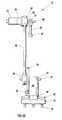
- FIG. 12shows a schematic isometric view of a sixth example of a highly accurate two-axis articulated coordinate measuring machine 210 , attached to a horizontal CNC lathe machine 114 for providing position feedback control, or for calibration purposes, according to the present invention.
- Two-axis ACMM 210comprises a support base 212 , adapted to be rigidly fixed to a working surface 120 (e.g. tail stock), relative to which the two-dimensional, axisymmetric spatial coordinates of the probe tip 230 can be measured.
- a working surface 120e.g. tail stock
- FIG. 12are means for converting the two measured angles of rotation ( ⁇ 1 and ⁇ 2 ) into cylindrical (e.g. axisymmetric) coordinates (R, Z).
- Probe tip 230can be a precision gauge ball, or other probe tip geometry, as needed.
- Tip 230can be magnetically attached to a three-point pivot mount 125 , which is rigidly attached to tool holder 126 , which holds tool 128 .
- Tool 128cuts workpiece 118 as it rotates about the axis of symmetry 122 .
- Workpiece 118is held by lathe chuck 116 , which is rotated by lathe motor 114 about the axis of symmetry 122 .
- ACMM 210includes a first revolute joint 214 that is mounted to post 248 .
- Joint 214has a first axis of revolution 216 , which is oriented perpendicular to the axis of symmetry 122 .
- first axis 216is nominally oriented horizontally.
- ACMM 210further includes a second revolute joint 218 .
- Second joint 218has a second axis of revolution 220 that is oriented parallel to the first axis of revolution 216 .
- ACMM 210includes a pair of rigid lower support arms 235 and 236 , having proximal ends rigidly connected to first joint 218 .
- Lower support arms 235 and 236each have a longitudinal axis aligned perpendicular to first axis 216 and perpendicular to second axis 220 .
- ACMM 210further includes a rigid upper support arm 228 , having a proximal end rigidly connected to the second joint 218 .
- Probe arm 228has a longitudinal axis aligned perpendicular to second axis 216 . Therefore, the plane in which the upper arm 228 rotates is parallel to the plane in which the lower support arms 235 and 236 rotate.
- ACMM 210includes a probe tip 230 , attached to the distal end of the probe arm 228 .
- Probe tip 230can be a precision gauge ball. However, other probe tip geometries, well-known to those skilled in the art, can be used in place of a gauge sphere (e.g. single touch probe, multiple touch probes, trigger probes, contact probe, constant-force touch probes, or non-contacting electrostatic or laser probes).
- ACMM 210further includes means for measuring the rotation angles ⁇ 1 , and ⁇ 2 of the first and second revolute joints 214 and 218 , respectively.
- ACMM 210can include a circular wheel 242 , which has a diameter greater than 4.5 inches, to provide sufficient angular accuracy.
- Wheel 242can have an optical encoder tape 244 wrapped around, and rigidly attached to, wheel 242 .
- Wheel 242can have a diameter of 4.85 inches, and can be wrapped with a Renishaw encoder tape 244 having 0.1 micron effective resolution, thereby providing an angular resolution of 3 counts/arcsecond.
- Base 212can have three spherical ball mounts 232 rigidly attached to the bottom of base 212 .
- Mounts 232can be arranged 120 degrees apart.
- Mounting plate 233is attached to tailstock 120 , and plate 233 has places to receive ball mounts 232 , thereby providing full kinematic constraint in 6-axes to base 212 .
- Probe tip 230can be used to provide real-time position feedback control during machining for the motion of tool holder 126 , holding tool 128 . Probe tip 230 can also be detached from three-point pivot mount 125 and used to check the surface profile of workpiece 118 during pauses in the machining cycle.
- FIG. 13shows a schematic isometric view of a seventh example of a highly accurate articulated coordinate measuring machine, with an wand 300 pivotally attached to probe arm 28 for use as a 3-D computer interface device, according to the present invention.
- Wand 300can be a rod or tube with a socket into which spherical probe tip 30 can be inserted to form a ball-and-socket (e.g. gimbaled) joint.
- Wand 300can be grasped by the hand or foot, and used to manipulate the position of probe tip 30 within a workspace, thereby providing 3-D spatial coordinate input to a computer software program.
- wand 300can be used to guide probe 30 , thereby functioning as a 2-D or 3-D computer mouse, for moving a computer cursor symbol in a virtual computer environment.
- FIG. 14shows a schematic isometric view of a eighth example of a highly accurate articulated coordinate measuring machine, according to the present invention.
- the second joint, joint 18can be compact, lightweight optical angle encoder 304 , such as a Canon K-1 laser angle encoder.
- FIG. 15shows a schematic isometric view
- FIG. 16shows a cross-section view, of a first example of a three-point pivot mount 125 , according to the present invention.
- Three-point pivot mount 125provides a low-friction, kinematic mount for rigidly holding spherical ball probe tip 30 in a stable, tripod-like geometry.
- Mount 125includes three precision-machined tooling balls 402 rigidly mounted to a cylindrical body 404 , and arranged approximately 120 degrees apart. This triangular arrangement provides for three points of contact with probe tip 30 .
- the three-points of contactconstrain all three translational degrees of freedom for probe tip 30 (e.g.
- Base 404houses a cylindrical magnet 408 , rigidly mounted along the centerline of body 404 .
- Non-magnetic annular ring 406provides separation between magnet 408 and body 404 .
- Ring 406can be made of aluminum.
- Magnet 408provides the force necessary to hold a magnetic probe tip 30 in contact with the three tooling balls 402 .
- the three tooling balls 402can be press-fit into body 404 .
- Ring 406 and magnet 408can be mounted in epoxy.
- three-point pivot mount 125can comprise a gimbaled geometry; a universal joint geometry, or a ball-and-socket geometry, depending on the requirements.
- Mount body 404can be magnetically attached to tool holder 126 , as shown in FIG. 12, or permanently attached via screws, or other well-known means.
- All machine tool and robotic arm position controllersare model-based, meaning that the controller uses a mathematical relation to convert motions occurring at the joint axes (e.g. three angles of revolution, ⁇ 1 , ⁇ 2 , and ⁇ 3 ) of the mechanism into the resulting motion at the tool tip (e.g. X, Y, Z of the probe tip 30 ).
- a kinematic modelmathematically describes how the individual motions of interconnected components in a mechanism contribute to the overall motion of the tool point.
- An accurate kinematic model for a particular mechanismwill provide accurate solutions for tool tip position, orientation (e.g. pose), velocity, and acceleration only if the values of the kinematic parameters upon which the model is based are an accurate reflection of the critical physical attributes of the system being controlled.
- Kinematic parameterstherefore, are the dimensions of the mechanism's components that directly govern the mechanism's positioning accuracy.
- the kinematic parametersinclude the link lengths (e.g. lengths between the axes of rotations for each pair of joints), twist angles, offset distances, and rotation angles at each joint.
- link lengthse.g. lengths between the axes of rotations for each pair of joints
- twist anglese.g. angle
- offset distancese.g. 1
- rotation anglese.g. 1
- rotation anglese.g. 1 relative to link 2 ; 2 relative to 3 ; and so on.
- the position of the probe tipmay be determined relative to the origin of the work frame.
- the present inventionhaving three serially-linked revolute joints (e.g. 3 degrees-of-freedom), there are thirteen independent kinematic parameters. Because the present invention is a serial device (e.g. having only serially linked joints), the basic kinematic parameters are not inherently cross-coupled. Since the calibration process for ACMM 10 relies on direct inspection, the measured kinematic parameters will not become cross-coupled during calibration.
- each kinematic parameterthere is an associated error that contributes to the total position error of the tool tip (e.g. probe tip 30 ).
- the tool tipe.g. probe tip 30
- a common three-axis milling machinehas a total of twenty-one individual kinematic parameters, each having their own errors.
- Many sourcescan contribute to each error, including: thermal effects, encoder accuracy and repeatability, imparted mechanical loads, imparted gravitational loads, bearing error motions (radial, face, tilt), and accuracy of device calibration.
- a total of 40 factorswere considered to contribute to the uncertainty in the thirteen kinematic parameters.
- the worst case combined uncertainty (e.g. error) in the reported position of the tool tipis 18 microns for the example of the present invention illustrated in FIGS.
- Calibration of the ACMM 10involves determining as best as possible all thirteen kinematic parameters.
- a large, gantry or bridge-style, three-axis orthogonal CMMe.g. a reference metrology tool having an accuracy much greater then ACMM 10
- the ultra-accurate, three-axis orthogonal CCMmeasures the position of the probe tip 30 as the tip is moved throughout the extremities of its workspace for a large number of poses (e.g. 250 poses).
- posese.g. 250 poses.
- a set of best-fit kinematic parameterscan be calculated that minimizes the average global error within the workspace.
- the present inventioncan include means for storing and using this set of best-fit kinematic parameters for the device.
- a second set of posesare measured by the reference metrology tool (e.g. ultra-accurate CMM machine).
- the reference metrology toole.g. ultra-accurate CMM machine.
- a residual error mapcan be created by comparing the apparent position of the probe tip (as reported by the calibrated ACMM 10 using the new, best-fit kinematic parameters) to the true position of the probe tip (as measured by the reference metrology tool).
- the error mapcan be represented mathematically by multi-variable polynomial functions.
- the present inventioncan include means for storing the residual error map in microprocessor memory.
- ACMM 10can include error-correction means for storing and using the residual error map to correct the position of the probe tip as reported by calibrated ACMM 10 .
- this error-correction procedurewould improve the accuracy of the ACMM 10 to the level of the reference metrology tool, which can be better than 0.0001 inches (e.g. 2.5 microns).
- FIG. 17shows a second example of a block diagram of the coordinate processing data collection and analysis system, according to the present invention.
- FIG. 17is identical to FIG. 11, except that two additional blocks have been added.
- a correction in this positionis then made by the host computer. This correction, as described above, is based on using Residual Error Map, which has been stored in the host computer's memory.
- the host computercalculates the probe tip's position relative to the ACMM's coordinate system.
- the method of using ACMM 10can comprise the following steps. Mounting plate 233 can be rigidly attached to working surface 100 or tailstock 120 . Base 12 is then mounted to plate 233 , while aligning mounting feet 32 in their respective matched pair of cylinders 510 . ACMM 10 is then initialized to a “home” position by placing probe tip 30 at the home location. This defines a reference “zero” for the angle encoders. Next, the probe tip 30 is moved to a new location, and the new position is computed by reading the angle encoders and converting the three angles to X,Y,Z coordinates by a microprocessor, as shown in FIG. 11 .
- the step of initializing the ACMM 10 to a home positioncan be skipped if absolute angle encoders are used, instead of incremental angle encoders.
- the microprocessorcan provide real-time error correction of the probe tip's position by updating the measured coordinates with reference to a residual error map stored in its memory.
- Probe tip 30can be moved by hand, if desired.
- Wand 300can be attached to probe tip 30 , and grasped by a hand to permit ease of manipulation, for example, during micro-surgery, or 3-D interfacing with a computer.
- probe tip 30can be placed into contact with three-point pivot mount 125 , which has been rigidly attached to a moving machine member (e.g. robotic arm, quill head of a milling machine, or tool holder of a lathe machine). This allow the motion of the moving member to automatically move and position probe tip 30 without human intervention (e.g. unattended operation). Such an arrangement would be useful for providing independent, real-time feedback control during machining operations.
- a moving machine membere.g. robotic arm, quill head of a milling machine, or tool holder of a lathe machine.
- three-point pivot mount 125can be inserted directly into the tool holder or end effector position, with probe tip 30 mounted to three-point pivot mount 125 . In this configuration, the three-dimensional positional performance of the machine tool or robotic arm can be rapidly assessed.
- FIG. 18shows a schematic side view of a ninth example of a metrology system 600 for providing independent, real-time, position feedback control, according to the present invention.
- System 600comprises an articulated coordinate measuring machine (ACMM) 10 , having a probe tip 30 pivotally mounted to a movable member 604 of a machine 602 .
- the machine shownis an articulated robotic arm 602 , having multiple axes of rotation, supported by a base 608 .
- Movable member 604has an end effector 605 for gripping parts 614 and lifting or moving them about the surface of table 616 .
- Data communications cable 612transfers coordinate data for the position of end effector 605 from robotic arm 602 to comparator processing means 616 .
- ACMM 10has three revolute joints, 14 , 18 , and 24 .
- Probe tip 30is attached to probe arm 28 .
- Probe tip 30is also pivotally mounted to pivot mount 125 .
- Pivot mount 125is rigidly attached to movable member 604 .
- Pivot mount 125can use magnetic means to allow the spherical ball of probe tip 30 to rotate freely in a low-friction kinematic mount, while simultaneously constraining translational motion with respect to the body of pivot mount 125 .
- ACMM 10can be kinematically mounted to base plate 233 .
- Base plate 233can be rigidly attached to the top surface of a heavy and rigid support base 606 . This arrangement provides a reference surface on which base plate 233 has a fixed spatial relationship to the machine's base 608 .
- FIG. 18shows an example where base 608 and base 606 are independent bases resting on a common surface (e.g. on the floor). Measurement accuracy is improved if the relative motion between bases 606 and 608 are minimized as much as possible.
- a laser interferometercould be used to measure and monitor any relative motions between the two separate bases. Alternatively, they can be combined into a single, continuous, heavy and rigid supporting structure (not shown).
- the electrical output of angle encoders for joints 14 , 18 , and 24 of ACMM 10can be transferred to comparator processing means 616 via data transmission cables 610 . Alternatively, wireless data communication means can be used in place of cables 610 .
- the movable member 604 of machine 602can be moved to a home position (not shown), which provides a repeatable, well-known position in the machine's coordinate system.
- Comparator processing means 616can include coordinate transformation means, such as illustrated in FIGS. 11 or 17 . Comparator processing means 616 compares the true position of the movable member 604 , as measured by the coordinate measuring device 10 , with the desired position of the movable member, as reported via cable 612 from robotic arm 602 . This creates a position error signal, which is useful for independently evaluating the spatial positional performance of movable member 604 (e.g., for meeting American National Standard ASME B5.54).
- comparator processing means 616can be used in FIG. 18 to calculate the position error of the movable member 604 by comparing the true position as measured by ACMM 10 with the desired position as commanded by robotic arm 602 .
- Comparator processing means 616can include electronic or microprocessor means for: (1) calculating the position error, (2) feeding back the error signal to the robotic arm's position controller (not shown), and (3) adjusting the position of movable member 604 , in real-time, in a manner that subsequently reduces the position error below an acceptable limit.
- a typical acceptable position error limitcould be ten microns.
- the required error limitcould be reduced to 0.0001 inches (e.g. less than 3 microns).
- coordinate measuring machine 10can be a portable, ACMM having six degrees of freedom, comprising three pairs of joints, where each pair of joints includes a revolute joint and a swivel joint.
- Commercially available versions of such a deviceare currently made by Romer, Inc. of Carlsbad, Calif.; and by Faro Technologies, Inc. of Lake Mary, Fla.
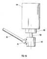
- movable member 104can be the quill or head of a conventional CNC three-axis milling machine.
- the tool holder of the milling machineis a rotating spindle 106 , which moves with member 104 .
- pivot mount 125includes a shaft 700 , which can be inserted and clamped into spindle 106 .
- the spherical ball of probe tip 30attached to probe arm 28 , can be magnetically, kinematically attached to pivot mount 125 .
- This arrangementplaces the probe tip 30 closer to the actual point of operation by replacing the conventional tool piece (e.g. drill bit, milling tool) with the shaft 700 of pivot mount 125 . Improved accuracy could be expected with this arrangement because the Abbe comparator offset error is reduced.
- FIG. 20shows a schematic side view of a eleventh example of a metrology system 601 for providing independent, real-time, position feedback control, or for evaluating the spatial positional performance, of a movable machine member, according to the present invention.
- a pair of independent, articulated coordinate measuring machines 10 and 610is attached on opposite sides of the moving machine member 104 .
- the second ACMM 610is also rigidly mounted to X-Y worktable 100 .
- Spherical ball probe tips 30 and 630are pivotally mounted to opposite sides of member 104 .
- the tips 30 and 630can be mounted with ball-and-socket joints 29 and 629 , respectively.
- ACMM 610can have a single lower support arm 622 , and circular wheel 654 is illustrated without any weight-reducing penetrations.
- FIG. 20where a pair of 3-axis ACMM's are placed on opposite sides of movable member 104 affords the possibility of measuring not only the three spatial coordinates for the 3-D position of member 104 , but also at least two coordinates for the orientation of member 104 . This is illustrated further in FIG. 21 .
- FIG. 21illustrates a “before” and “after” position for the machine head 104 , rotating spindle tool holder 106 , machine tool 110 , and pivotally mounted probe tips 30 and 630 .
- the operation point of tool 110is indicated by point “P”.
- thermal distortions or mechanical errorscan cause both the position and orientation of member 104 to move, thereby creating both a position error and an orientation error.
- the illustration shown in FIG. 21greatly magnifies an example of errors in both position and orientation.
- the use of a pair of 3-axis CMM's mounted on opposite sidescan measure all three orientation errors.
- any rotation of member 104 around an axis drawn between the two contact points of probe tips 30 and 630e.g. line A-B
- the addition of a second ACMM 610provides a second, independent measure of the translation of member 104 , which can be averaged with that measured by the first ACMM 10 .
- One solution to this problemis to add a third 3-axis ACMM (not shown), having a third probe tip pivotally attached to a third location on member 104 .
- a third 3-axis ACMM(not shown), having a third probe tip pivotally attached to a third location on member 104 .
- all three degrees of translation, and all three degrees of rotation (e.g. orientation) of movable member 104can be independently measured and evaluated.
- FIG. 22shows a schematic side view of a thirteenth example of a metrology system for using a movable member 104 of a machine to perform automatic, machine-guided inspection of the spatial dimensions of a part 102 , according to the present invention.
- member 104represents the quill of a conventional CNC three-axis milling machine.
- Part 102is clamped to X-Y worktable 100 .
- a precision tooling ball 800with stem shaft 802 , is inserted into spindle tool holder 106 .
- Probe arm 28 of ACMM 10has a pivot mount 125 attached to the distal end of arm 28 .
- Tooling ball 800engages pivot mount 125 and is held in place with magnetic means.
- a touch probe assembly 80Attached to the far side of pivot mount 125 is a touch probe assembly 80 , comprising five touch probes.
- the inspection of part 102which can be a partially machined part that is still clamped to worktable 100 , can be performed automatically by machine member 104 .
- the 3-axis milling machineis programmed to move member 104 (with attached multi-probe 80 ), so that the probe tip(s) contact a variety of positions on partially-machined part 102 , whereby the dimensions of part 102 is accurately measured. In this way, machine member 104 automatically guides the motion of probe arm 28 throughout the inspection program in an unattended fashion.
- FIG. 23shows a schematic block diagram of an example of a method of providing independent, real-time position feedback control of a movable machine member.
- the movable machineis a 3-D milling machine, having a milling head (e.g. quill) with a pivotally attached probe tip 30 belonging to ACCM 10 .
- a NC programor other input control scheme, provides a command to the milling machine's position controller to move the milling head to a desired position.
- the position controllerprovides commands to the X,Y,Z motor drives, which move the milling head appropriately.
- ACCM 10measures the true position of the milling head.
- a computer microprocessorcompares the true (actual) measured position with the desired, and creates a position error signal representative of the error between the desired and actual position of the milling head.
- the position error signalis fed back to the milling machine's position controller in a closed-loop manner, thereby correcting the position.
- This closed-loop cyclerepeats as many times as is necessary to reduce the position error signal below a predetermined limit, such as ten microns.
- FIGS. 24A and 24Bshow a top view and a side view, respectively, of an example of a one DOF articulated coordinate measuring machine (ACMM) 10 .
- ACCM 10has a single revolute joint comprising an encoder wheel 902 that rotates about an axis of rotation that is substantially perpendicular to working surface 8 .
- Riser 904is attached to wheel 904 , and holds probe arm 28 with probe tip 30 .
- Bearing means 906comprises two ball bearings and a shaft.
- Sensor 5detects the motion of marks disposed on the circumference of wheel 902 as the wheel rotates.
- This example of a single DOF ACCMcan be used to evaluate the performance of another CMM by tracing out a highly accurate circle (not shown), defined by the motion of probe tip 30 , where the plane of the circle is parallel to the working surface 8 .
- a method of performing this taskis described in U.S. Pat. No. 5,341,574, “Coordinate Measuring Machine Test Standard Apparatus and Method”, by L. Bieg (same as the present co-inventor), which is herein incorporated by reference.
- FIGS. 25A and 25Bshow a top view and a side view, respectively, of an example of a two DOF articulated coordinate measuring machine (ACMM) 10 .
- ACCM 10has a single revolute joint comprising an encoder wheel 902 that rotates about an axis of rotation that is substantially perpendicular to working surface 8 .
- Probe arm 28comprises linear measuring means 908 for measuring changes in the length of arm 28 (e.g. LVDT or laser interferometer).
- This example of a two DOF ACCMcan be used to evaluate the performance of a movable machine member as it is driven to trace out a circle, where the plane of the circle is parallel to the working surface 8 . Deviations from a perfect circle are indicated by changes in the length of probe arm 28 as measured by means 908 .
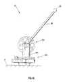
- FIG. 26shows a side view of an example of a two DOF articulated coordinate measuring machine (ACMM) 10 .
- ACCM 10has a first revolute joint 910 , comprising an encoder wheel and sensor, that has an axis of rotation perpendicular to working surface 8 .
- ACCM 10further has a second revolute joint 912 , also comprising an encoder wheel and sensor, that has an axis of rotation that is parallel to working surface 8 .
- These two revolute joints, 910 and 912are serially linked by support arm 911 .
- This example of a two DOF ACCMcan be used to evaluate the performance of another CMM by tracing out a highly accurate hemispherical surface (not shown), defined by the motion of probe tip 30 .
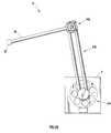
- FIG. 27shows a side view of an example of a three DOF articulated coordinate measuring machine (ACMM) 10 .
- FIG. 27is similar to FIG. 26, except that probe arm 28 comprises linear measuring means 913 for measuring changes in the length of arm 28 (e.g. LVDT or laser interferometer).
- linear measuring means 913for measuring changes in the length of arm 28 (e.g. LVDT or laser interferometer).
- This example of a three DOF ACCMcan be used to evaluate the performance of a movable machine member as it is driven to trace out a hemispherical surface. Deviations from a perfect hemispherical surface are indicated by changes in the length of probe arm 28 as measured by means 913 .
- FIG. 28shows a top view of an example of a two DOF articulated coordinate measuring machine (ACMM) 10 .
- FIG. 27is similar to FIG. 12, except that both axes of revolution for revolute joints 914 and 916 are perpendicular to working surface 8 .
- This example of a two DOF ACCMcan be used to trace the X-Y planar contour of a solid part lying on working surface 8 , which can be a table.
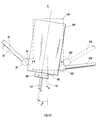
- FIG. 29shows a side view of an example of a single DOF articulated coordinate measuring machine (ACMM) 10 .
- FIG. 27is similar to FIG. 26, except that riser 13 is rigidly fixed to base 12 , and does not rotate. The axis of revolution for revolute joint 920 is parallel to working surface 8 .
- This example of a single DOF ACCMcan be used to evaluate the performance of another CMM by tracing out a highly accurate half-circle (not shown) defined by the motion of probe tip 30 , where the plane of the half-circle is perpendicular to the working surface 8 .
- FIG. 30shows a side view of an example of a two DOF articulated coordinate measuring machine (ACMM) 10 .
- FIG. 30is similar to FIG. 29, except that probe arm 28 comprises linear measuring means 922 for measuring changes in the length of arm 28 (e.g. LVDT or laser interferometer).
- linear measuring means 922for measuring changes in the length of arm 28 (e.g. LVDT or laser interferometer).
- This example of a two DOF ACCMcan be used to evaluate the performance of a movable machine member as it is driven to trace out a half-circle arc. Deviations from a perfect half-circle arc are indicated by changes in the length of probe arm 28 as measured by means 922 .
- the present inventioncan comprise a method of independently evaluating the spatial positional performance of a movable machine member, comprising: a) kinematically mounting the base of an articulated coordinate measuring machine to a working surface at a location having a fixed spatial relationship to a home position on the machine, wherein the coordinate measuring machine has a probe tip and at least two serially-linked revolute joints; b) pivotally mounting the probe tip to the movable machine member; c) commanding the machine's position controller to move the movable machine member to a home position; d) initializing the coordinate system of the coordinate measuring machine while at the home position; e) commanding the machine's position controller to move the movable machine member to a desired position; f) measuring the position of the movable machine member with the coordinate measuring machine to create a true position; g) comparing the true position with the desired position to create a position error; and h) repeating steps e) through g) as often needed to evaluate the spatial positional performance of the movable
- the step f of measuring the position of the movable machine membercan be performed dynamically while the movable machine member is moving.
- the ACMMtakes a “snapshot” of the position of the machine member while it is moving.
- the step f) of measuring the position of the movable machine membercan be performed statically after the movable machine member has completed the previous step e) of moving to a desired position and has stopped moving.
- the present inventioncan comprise a method of: a) using a reference metrology tool having an accuracy that is greater than the accuracy of the coordinate measuring device to calibrate the device; b) generating a set of best-fit kinematic parameters that minimizes the average global error within the device's workspace; c) storing the set of best-fit kinematic parameters within a microprocessor; and d) using the set of best-fit kinematic parameters for computing the position of the probe tip.
- step e)after performing step d), then calculating a residual error by comparing the apparent position of the probe tip as reported by the calibrated coordinate measuring device using the set of best-fit kinematic parameters from step b) above, to the true position of the probe tip as measured by the reference metrology tool; f creating a residual error map by performing step e) for a plurality of probe tip positions; g) storing the residual error map within the microprocessor; and h) correcting, in real-time, the apparent position of the probe tip by using the residual error map to adjust the probe's position so that the actual error is reduced below an acceptable limit.
- the present inventioncan comprise a method of: a) kinematically mounting the base of a second articulated coordinate measuring device to a reference surface at a second location having a second fixed spatial relationship to the home position on the machine, the second coordinate measuring device having a second probe tip; b) pivotally mounting the second probe tip to a second position on the movable member; c) commanding the machine's position controller to move the movable member to a home position; d) initializing both the first and the second coordinate systems of the coordinate measuring devices while at the home position, while accounting for the separation distance between the first and second positions; e) commanding the machine's position controller to move the movable member to a desired position; f) measuring a first true position of the movable member with the first coordinate measuring device; g) measuring a second true position of the movable member with the second coordinate measuring device; h) comparing the first and second true positions with the desired position to create a pair of position errors; i) comparing the first and second true positions with
- the present inventioncan comprise a method of providing independent, real-time, position feedback control of a movable machine member, comprising: a) kinematically mounting the base of a articulated coordinate measuring device to a reference surface at a location having a fixed spatial relationship to a home position on the machine, the coordinate measuring device having a probe tip, and having at two serially-linked revolute joints; b) pivotally mounting the probe tip to the movable member; c) commanding the machine's position controller to move the movable member to the home position; d) initializing the coordinate system of the coordinate measuring device while at the home position; e) commanding the machine's position controller to move the movable member to a desired position; f) measuring the true position of the movable member with the coordinate measuring device; h) comparing the true position with the desired position to create a position error; i) feeding back the position error to the position controller of the machine's movable member; j) adjusting the position of the movable member to reduce
- the step f) of measuring the position of the movable machine membercan be performed dynamically while the movable machine member is moving.
- the ACMMtakes a “snapshot” of the position of the machine member while it is moving.
- the step f) of measuring the position of the movable machine membercan be performed statically after the movable machine member has completed the previous step e) of moving to a desired position and has stopped moving.
- the present inventioncan comprise a method of using a movable machine member to perform automatic, machine-guided inspection of the spatial dimensions of a part, comprising: a) mounting the base of a articulated coordinate measuring device to a reference surface at a location having a fixed spatial relationship to a home position on the machine, the coordinate measuring device having a probe tip, and having at two serially-linked revolute joints; b) pivotally mounting the probe tip to the movable member; c) commanding the machine's position controller to move the movable member to the home position; d) initializing the coordinate system of the coordinate measuring device while at the home position; e) commanding the machine's position controller to move the movable member, including pivotally mounted probe tip, into close proximity to a plurality of locations on the part; and automatically scanning the surface of the part, whereby the spatial dimensions of the part are measured and inspected.
- the probe tipcan comprise a plurality of touch probes.
- the present inventioncan comprise the method of performing manual inspection of the spatial dimensions of an at least partially machined part, comprising: a) mounting the base of a articulated coordinate measuring device to a reference surface at a location having a fixed spatial relationship to a home position on the machine, the coordinate measuring device having a probe tip, and having at two serially-linked revolute joints; b) at least partially machining the part; c) manually moving the movable member to the home position; d) initializing the coordinate system of the coordinate measuring device while at the home position; e) manually moving the probe tip into close proximity to a plurality of locations on the part, during a pause in machining; and f) measuring the true position of the probe tip with the coordinate measuring device; whereby the spatial dimensions of the at least partially machined part are measured and inspected.
- One advantage of this methodis that accuracy is enhanced by not removing the at least partially machined part from the worktable and transporting it to (and from) a separate gantry or bridge-style CMM located far away from the
- the system using ACMM 10can be used to precisely measure the spatial location of a moving articulated robot arm.
Landscapes
- Physics & Mathematics (AREA)
- General Physics & Mathematics (AREA)
- Length Measuring Devices With Unspecified Measuring Means (AREA)
Abstract
Description
This application is related to application “Position Feedback Control System”, by Lothar F. Bieg, et al. of Albuquerque, N.Mex., Ser. No. 09/692,024, now U.S. Pat. No. 6,519,860, commonly assigned to Sandia Corporation, Albuquerque, N.Mex.
The United States Government has rights in this invention pursuant to Department of Energy Contract No. DE-AC04-94AL85000 with Sandia Corporation.
This invention relates generally to the field of precision machining, and more specifically to an articulated coordinate measuring machine (ACMM), system, and method for providing independent, real-time position feedback control during precision machining.
Traditionally, the position of a movable machine member (e.g. tool holder or end effector) is determined indirectly by sensing motion at a large distance away from the actual point of operation. For example, the linear motion of a slide for a worktable is derived indirectly from rotational motion of a motor and lead screw combination by using a angle encoder or resolver. Another example is the use of a linear scale located adjacent to a guideway. These indirect methods have limited accuracy due to the well-known Abbe-offset error effect (e.g. comparator error). The accuracy can also be degraded by (1) thermal distortion effects induced by operation of the machine itself (e.g. motor heat from driving a tool under load, and spindle heating due to friction), or by an uncontrolled thermal environment; and (2) by progressive wear or aging of drive gears, guideways, etc. These problems become even more severe as the number of degrees of freedom (DOF) increases, such as a serially-linked 6-axis robotic arm manipulator, or a parallel-linked 6-axis Hexapod or Rotopod machine.
In-process inspection and Statistical Process Control requirements have forced the need to periodically re-certify the manufacturing process. Traceability of the machining process, and quick performance evaluation within the required workspace, can be critically important for small lot size and one-of-a-kind fabrication. The American National Standard ASME B5.54 provides rules for determining the three-dimensional positional performance of computer numerically controlled (CNC) systems. Satisfying the specifications of ASME B5.54 usually requires a multitude of expensive and sensitive equipment, applied by trained experts.
For straightness evaluation of a single machine tool axis, a laser interferometer or a series of calibrated, multiple-length gauge blocks can be used. For two-dimensional positional performance, a precision variable-length ball-bar is recommended. For three-dimensional positional performance (e.g. volumetric), the length of a fixed ball-bar should be measured in 20 different locations along the edges, face diagonals, and body diagonals of a cubical work zone. For non-cubical work zones, the number of positions can increase to 30-35 positions. A need exists, therefore, for a rapid, yet accurate multi-dimensional metrology system for calibrating precision machine tools.
Despite the need for increased accuracy and speed, such a metrology tool should remain a lightweight and portable unit. This would allow a single coordinate measuring machine (CMM) to periodically check and certify an entire shop floor having a multitude of equipment.
Statistical process control (SPC) has been successfully used for quality control of high volume manufacturing. However, as product diversity increases, and lot size decreases, the desire to minimize or eliminate independent product inspections has grown. This has created a new requirement for total process control (TPC), where all of the factors influencing the production process are detected, analyzed, and controlled, preferably in real-time. For this reason, an independent, real-time position feedback control system is needed to build Total Process Control (TPC) into the manufacturing process.
As explained above, real-time position measurement systems used on conventional precision machines suffer from a number of errors (e.g. comparator offset, thermal distortion, and wear of sliding surfaces). An ideal metrology system would directly measure the precise location of the actual cutting point of a machine tool, spray head, etc. during operation.
Laser trackers can provide non-contact, real-time measurement in three dimensions of a retroreflector sphere or cube mounted to a surface. These devices utilize a motorized, gimbal-mounted laser interferometer, which tracks the moving retroreflector (such as the SMX-4500 Laser Tracker manufactured by Spatial Metrix Corp., or a SMART310e Laser Tracker manufactured by Leica, Inc.). However, a laser retroreflector can not be practically mounted to an actual spinning drill bit or cutting tool. More importantly, if an object obstructs the laser beam, tracking can be lost. Operation must be paused to allow re-acquisition of the reflecting target mirror. Generation of cutting chips or small particles during machining operations and large volumes of cutting cooling fluids, can obstruct the laser beam and prevent useful application for real-time position control. End effectors mounted on the end of robotic arms, such as paint sprayers, thermal spray heads, plasma spray heads, sand blasters, grinders, etc. can also produce large volumes of particulates or dust that obscure laser beams, 3-D vision systems, or other non-contact sensors. 3-D laser tracking devices are generally very expensive, in the range of $ 125-250 K.
A need exists, therefore, for a position measurement device that remains in solid contact with the moving member, ideally as close as possible to the cutting tool or point of operation. If the probe tip is physically attached to the moving member, then cutting chips, particulates, and fluids should not interfere with the ACMM's operation. Ideally, the apparatus would not intrude on the work zone. Also, the device should have a low inertia, so as not to interfere with the rapid motion of the moving member. Such a device should be lightweight, low cost, have low vibrations, have a large range of motion, and a high accuracy. The data collection system of the system should be capable of processing position measurements at a sufficiently high data rate, commensurate with providing real-time feedback to a rapidly moving machine member. The accuracy of such a system should be better than 10 microns, preferably better than 3 microns. Such a system should be easily mounted on, or near, existing machines with minimal structural modifications.
If the probe tip of the ACMM is physically mounted with a pivoting joint to the moving member of the machine tool, the ACMM's probe could be automatically guided by the moving member through all extremes of the workspace. This could make the application of the ACMM simple and automatic; requiring little skill or training. Existing feedback systems, i.e. resolvers, encoders, linear scales, etc. could be used for the servo controls velocity feedback loop, while using the independent position feedback of a pivotally mounted CMM for the displacement feedback loop.
Gantry or bridge-style fixed 3-axis orthogonal (e.g. Cartesian) CMM's provide outstanding accuracy (better than 0.0001 inches), but are typically very expensive and are not portable.
Multi-axis, portable CMM's (ACMM's) are commercially available from Romer, Inc. of Carlsbad, Calif. and by Faro Technologies, Inc. of Lake Mary, Fla. However, their accuracy is limited to about 0.001-0.005 inches. These portable ACMM's have six degrees-of-freedom (one rotation axis and one swivel axis at each of the three joints, linked by two support arms). Six degrees-of-freedom (DOF's) provides the ability to easily position the probe tip underneath and behind complex shapes, without having to reposition the base. The use of rotary joints also minimizes errors due to torques and bending moments. Precision rotary transducers (e.g. angle encoders) are mounted at each of the six joints. Their data are used to calculate the probe's position in three-dimensional Cartesian space. The measuring volume is generally spherical, with the radius equal to the maximum reach of the linked arms, typically a 3-6 foot radius. The tubular support arms are typically made of a lightweight and stiff material, such as an aluminum alloy, or a carbon fiber composite.
A need exists, therefore, for a low-cost, portable ACMM that has sufficient accuracy for providing in-process inspection of part features while the part is still mounted on the machine (during pauses in the machining cycle). This would eliminate the need to remove the part and transport it to a fixed, large gantry or bridge-style CMM inspection station. Use of an independent, in-process inspection tool can save time, and eliminate potential errors in re-positioning the part when machining starts-up again.
Some machine tools, such as horizontal and vertical lathes, rotate the workpiece during machining. In this case, because the workpiece geometry is axisymmetric, only 2 degrees-of-freedom are required (e.g. travel down the centerline, Z-axis, and radial extension, R-axis). Consequently, a highly accurate ACMM, mounted to, for example, the tail stock frame of a horizontal lathe, and would only need two independent axes of revolution to provide complete measurement for a lathe-type machine tool. A 2 DOF ACMM could also be used for measuring the contour of a part in a flat, 2-D plane (e.g. X-Y plane). An ACMM with only 1 DOF could be used for performance evaluation and calibration of gantry-style 3-axis orthogonal CMM's.
Electro-Discharge Machining (EDM) of metal parts involves passing a high current through a wire or sinker electrode, and spark-eroding the workpiece. Due to the high voltages involved, it would be useful if a highly accurate ACMM could withstand high voltages without damage.
Despite the need for increased accuracy, a highly accurate ACMM should remain a lightweight and portable tool. This allows a single metrology tool to periodically check and certify an entire shop floor having a multitude of equipment. The tool should be easily mounted on a working surface on, or near, existing machines. The tool should be capable of hands-off operation (e.g. unattended), after initial setup.
Many approaches can be used to improve the accuracy of ACMM's to better than 0.001 inches. One method would be to reduce the number of serially linked joints (e.g. from six down to three) because the total position error builds upon the individual position errors for each joint linked in series.
Another method to improve the accuracy of ACMM's would be to increase the accuracy of the angle encoder(s). One approach would be to wrap a linear encoder tape with a fine line pitch (e.g. fine gradation of marks) around the outside circumference of a circular encoder wheel. As the diameter of the wheel increases, so does the circumference. The larger circumference generates a proportionally larger number of counts (e.g. count rate) sensed by a read head for the same angle of rotation, as compared to a wheel having a smaller diameter that is wrapped with an encoder tape having the same line pitch. Likewise, for the same number of line counts, a wheel having a larger diameter will rotate a smaller angle than a wheel having a smaller diameter. Consequently, the angular accuracy can be increased essentially without limit by increasing the diameter of a wheel that has a linear encoder tape wrapped around the wheel's circumference.
Conventional ACMM's have not adopted this approach because the increased weight of the larger diameter encoder wheels reduces the ease of portability, while the increased size could interfere with physical access behind surfaces and inside of small work volumes. Also, it wasn't until recently that flexible, highly accurate optical or inductive encoder tapes became commercially available in a configuration suitable for wrapping around the circumference of a wheel, at an affordable cost.
Accuracy of the ACMM could also be increased by (1) using materials with a low thermal expansion coefficient, (2) requiring very tight machining tolerances, (3) using high precision ball or roller bearings (e.g. ABEC grade 7-9 ball bearings), and (4) using highly accurate angle encoders (e.g. increasing from 81,000 counts per revolution to 230 million counts per revolution). However, these changes generally increase the overall cost of the ACMM.
A need exists, therefore, to reduce the costs of ACMM's, while enhancing accuracy. This can be achieved, in part, by reducing the number of DOF's (e.g. from 6 to 3), which eliminates excess bearings, angle encoders, machining, etc. Also, use of large diameter encoder wheels and wrapped encoder tapes can reduce the costs, as compared to more expensive, commercially available compact laser angle encoders (e.g. Canon K-1 angle encoder).
Reducing the number of DOF's from six to three could eliminate the need to use two hands to support the serially linked arms. This could also eliminate the need for counterbalancing the arms with springs or weights.
Use of a highly accurate articulated coordinate measuring machine (ACMM) mounted on a working surface, on or near, the machine tool or robotic arm, and having a probe tip pivotally-mounted to the movable machine member, could provide independent, real-time position feedback control needed to build Total Process Control (TPC) into the manufacturing process.
Other applications of using a highly accurate articulated coordinate measuring machine include 3-D digitizing/tracing of surfaces and solid objects; 3-D spatial interfacing with a computer (e.g. a 3-D mouse/joystick); 3-D sculpting via a master-slave arrangement; and remote surgery or micro-surgery via a master-slave arrangement.
FIG. 1A shows a schematic top view of a first example an articulated coordinate measuring machine having a single degree of freedom, according to the present invention.
FIG. 1B shows a schematic side view of a first example of an articulated coordinate measuring machine having a single degree of freedom, according to the present invention.
FIG. 1C shows the geometric relationships between the two serially-linked arms, the three angles of revolution, and the probe point “P”, according to the present invention.
FIG. 2 shows a schematic isometric view of a second example of a highly accurate articulated coordinate measuring machine, according to the present invention.
FIG. 3 shows a first example of a magnetic kinematic mount for holding the base, according to the present invention.
FIG. 4 shows a schematic isometric view of a third example of a highly accurate articulated coordinate measuring machine, according to the present invention.
FIG. 5ashows a schematic isometric view of a third example of a highly accurate articulated coordinate measuring machine, according to the present invention.
FIG. 5bshows a schematic side view of a third example of a highly accurate articulated coordinate measuring machine, according to the present invention.
FIG. 5cshows a schematic top view of a third example of a highly accurate articulated coordinate measuring machine, according to the present invention.
FIG. 5dshows a schematic backside view of a third example of a highly accurate articulated coordinate measuring machine, according to the present invention.
FIG. 6 shows a schematic cross-section view of a third example of a highly accurate articulated coordinate measuring machine, according to the present invention.
FIG. 7 shows a schematic isometric exploded view of a second example of the third revolute joint of the third example of a highly accurate articulated coordinate measuring machine, according to the present invention.
FIG. 8 shows a schematic view of a first example of probe tip body having multiple touch probes, according to the present invention.
FIG. 9 shows a schematic isometric view of a fourth example of a highly accurate articulated coordinate measuring machine, attached to a 3-axis CNC milling machine for providing position feedback control, or for calibration purposes, according to the present invention.
FIG. 10 shows a schematic isometric view of a fifth example of a highly accurate articulated coordinate measuring machine, attached to a 3-axis CNC milling machine for providing position feedback control, or for calibration purposes, with a flexible bag or bellows surrounding the ACMM, according to the present invention.
FIG. 11 shows a first example of a block diagram of the position data collection and analysis system, according to the present invention.
FIG. 12 shows a schematic isometric view of a sixth example of a highly accurate two-axis articulated coordinate measuring machine, attached to a horizontal CNC lathe for providing position feedback control, or for calibration purposes, according to the present invention.
FIG. 13 shows a schematic isometric view of a seventh example of a highly accurate articulated coordinate measuring machine, with an attached wand for using as a 3-D computer interface device, according to the present invention.
FIG. 14 shows a schematic isometric view of a eighth example of a highly accurate articulated coordinate measuring machine, according to the present invention.
FIG. 15 shows a schematic isometric view of a first example of a three-point pivot mount, according to the present invention.
FIG. 16 shows a schematic cross-section view of a first example of a three-point pivot mount, according to the present invention.
FIG. 17 shows a second example of a block diagram of the position data collection and analysis system, according to the present invention.
FIG. 18 shows a schematic side view of a ninth example of a metrology system for providing independent, real-time, position feedback control, according to the present invention.
FIG. 19 shows a schematic side view of a tenth example of a metrology system for independently evaluating the spatial positional performance of a movable machine member, according to the present invention.
FIG. 20 shows a schematic side view of a eleventh example of a metrology system for providing independent, real-time, position feedback control, according to the present invention, including a pair of 3-axis articulated coordinate measuring machines, attached on either side of the moving machine member.
FIG. 21 shows a schematic side view of a twelfth example of a metrology system for providing independent, real-time, position feedback control, according to the present invention, including a pair of 3-axis articulated coordinate measuring, machines, attached on either side of the movable machine member, which provides information about the position and orientation of the movable machine member.
FIG. 22 shows a schematic side view of a thirteenth example of a metrology system for using a movable machine member to perform automatic, machine-guided inspection of the spatial dimensions of a part, according to the present invention.
FIG. 23 shows a schematic block process diagram of a process for providing real-time feedback control, according to the present invention.
FIG. 24A shows a schematic top view of an example of an articulated coordinate measuring machine, according to the present invention.
FIG. 24B shows a schematic side view of an example of an articulated coordinate measuring machine, according to the present invention.
FIG. 25A shows a schematic top view of an example of an articulated coordinate measuring machine, according to the present invention.
FIG. 25B shows a schematic side view of an example of an articulated coordinate measuring machine, according to the present invention.
FIG. 26 shows a schematic side view of an example of an articulated coordinate measuring machine, according to the present invention.
FIG. 27 shows a schematic side view of an example of an articulated coordinate measuring machine, according to the present invention.
FIG. 28 shows a schematic side view of an example of an articulated coordinate measuring machine, according to the present invention.
FIG. 29 shows a schematic side view of an example of an articulated coordinate measuring machine, according to the present invention.
FIG. 30 shows a schematic side view of an example of an articulated coordinate measuring machine, according to the present invention.
This invention relates generally to the field of precision machining, and more specifically to a system and method for providing independent, real-time position feedback control during precision machining. This invention also relates to an articulated coordinate measuring machine (ACMM). The ACMM is kinematically mounted to a working surface (e.g. worktable or frame). The ACMM's probe tip can be physically attached to a movable machine member (e.g. a machine tool holder, or end effector of a robotic arm) to provide independent, real-time measurement of the member's position in one, two, or three-dimensional Cartesian space. The true measured position (e.g. true position) can then be compared, in real-time, to the desired position to create a position error signal that is useful for evaluating the performance of the movable machine, or for providing closed-loop position feedback control. An ACMM with three degrees-of-freedom can be described as a 3D Ball Bar™.
FIGS. 1A and 1B show a schematic top view and side view, respectively, of a first example of an articulated coordinate measuring machine (ACMM)10 having at least a single degree of freedom, according to the present invention.ACMM 10 comprises acircular encoder wheel 1, having an axis ofrotation 2. A plurality ofmarks 3 are disposed around at least a portion of the circumference of theencoder wheel 1. The marks can be lines, circles, oval, or other shapes. The marks can be uniformly or non-uniformly spaced apart. The lines can be spaced 20 microns apart. Non-uniformly spaced marks can provide the ability to determine the absolute angular position. The plurality ofmarks 3 can be ruled directly onto the surface of the circumference ofencoder wheel 1. Ruling of marks can include precision machining or scratching of lines, deposition of lines via micro-lithographic techniques, or the creation of pits via laser beam ablation.ACMM 10 further comprises bearing means4 for supportingencoder wheel 1 while permitting free rotation ofwheel 1 about axis ofrotation 2. Bearing means4 can be an air bearing, providing essentially frictionless support. Alternatively, bearing means4 can include roller or ball bearings. Asensor 5 is rigidly attached to bearing means4, and is used for detecting the motion of at least some of themarks 3 as theencoder wheel 1 rotates.Sensor 5 can comprise an optical detector, inductive detector, or magnetic detector.ACMM 10 further comprises aprobe arm 6, having a proximal end rigidly attached toencoder wheel 1, and having a distal end with aprobe tip 7 attached thereto.ACMM 10 further comprises a means (not shown) for kinematically constrainingACMM 10 to a workingsurface 8.ACMM 10 further comprises coordinate processing means9, operatively connected tosensor 5, for converting the output ofsensor 5 into a set of cylindrical coordinates representing the position ofprobe tip 7 relative to a reference cylindrical coordinate system (not shown). The set of cylindrical coordinates can represent the incremental position ofprobe tip 7, relative to a previously known position. Processing means9 can be connected tosensor 5 withcable 11. Wireless communication means (not shown) can also be used to transmit information fromsensor 5 to processing means9. Processing means9 can comprise a microprocessor with memory storage. Processing means9 can comprise means for converting the cylindrical coordinates into Cartesian (e.g. X,Y) coordinates.
FIG. 2 shows a schematic isometric view of a second example of a highly accurate articulated coordinate measuring machine (ACMM)10, according to the present invention.ACMM 10 comprises asupport base 12, adapted to be rigidly fixed to a working surface (e.g. worktable or frame)100, that the three-dimensional spatial coordinates of theprobe tip 30 can be measured relative to. Alternatively,base 12 can be adapted to be fixed relative to working surface100 (e.g. on a tripod or rigid stand, not shown). FIG. 2 illustrates that the dimensions of amachined part 102 can be measured or probed by “touching” the surface ofpart 102 withprobe tip 30. Here, the word “touching” broadly contemplates the use of non-contact probe tips, such as laser-probes and electrostatic probes. Not shown in FIG. 2 are means for converting the measured angles of rotation (θ1, θ2, θ3) into Cartesian coordinates X, Y, and Z.ACMM 10 can be used to evaluate and calibrate a 6-axis portable CMM, such as commercially manufactured by Romer, Inc. of Carlsbad, Calif.; and by Faro Technologies, Inc. of Lake Mary, Fla. ). Alternatively,part 102 can be a precision, certified metrology artifact (e.g. gauge sphere, bar, square, or cube). In this case, the accuracy ofACMM 10 can be evaluated and calibrated by measuring acertified artifact 102 withACMM 10. Probetip 30 can be a precision gauge ball, or other probe tip geometry, as needed.
Referring to FIG. 2,ACMM 10 comprises a first revolute joint24, rigidly attached to the distal end offirst support arm 22. In FIG. 2,first support arm 22 is illustrated as a pair of parallel tubes. First joint24 has a first axis ofrevolution 26, which can be oriented substantially parallel tosecond axis 20.First axis 26 can be oriented substantially perpendicular to the longitudinal axis oflower support arm 22. ACMM 10 further includes arigid probe arm 28, having a proximal end rigidly connected to the first joint24.Probe arm 28 has a longitudinal axis aligned substantially perpendicular tothird axis 26. Therefore, the plane in which probearm 28 rotates is substantially parallel to the plane in which thefirst support arm 22 rotates.
Referring still to FIG. 2,ACMM 10 comprises a third revolute joint14 that is rotatably mounted tobase 12. Third joint14 has a third axis ofrevolution 16, which is oriented substantially perpendicular to the broad plane ofbase 12. In the example shown in FIG. 2,third axis 16 is nominally oriented vertically (as in a turntable).ACMM 10 further includes a second revolute joint18, rotatably mounted to the third joint14. Second joint18 has a second axis ofrevolution 20 that is oriented substantially perpendicular to, and intersecting with, the third axis ofrevolution 16.ACMM 10 includes a rigidfirst support arm 22, having a proximal end rigidly connected to second joint18.First support arm 22 has a longitudinal axis aligned substantially perpendicular tosecond axis 20.Second support arm 23 has a distal end rigidly attached to second joint18, and has a proximal end rigidly attached to third joint14.
FIG. 3 shows a first example of a magnetickinematic mount 233 for rigidly holding base12 (not shown) to a working surface, such assurface 100 in FIG. 2, or to tailstock120 in FIG. 12, according to the present invention.Kinematic mount 233 can include arigid plate 502, with threemagnets 504 rigidly attached toplate 502, preferably arranged approximately 120 degrees apart, around acentral point 501 defined by the intersection of threeaxes 512.Magnets 504 provide the force for holding downbase 12 toplate 502. Other well-known methods of attachingbase 12 can be used, such as clamping, vacuum mounting, etc. Additionally, a spring (not shown) can be attached to the bottom ofbase 12 at one end, and to theplate 502 at the other end, to provide additional holding force.Plate 502 can be rigidly attached to surface100 (or tailstock120) via bolts engaged through a plurality of mountingholes 506.
Referring still to FIG. 3, mountingfeet 32 withstem 33 can be disposed in approximately 120 degrees apart, aboutcentral point 501, in-line with axes512 (e.g. approximately rotated60 degrees from magnets504). Each mountingfoot 32 contacts a pair ofcylinders 510, thereby providing a two-point contact. Pair ofcylinders 510 is rigidly attached toplate 502, and rest partially inside ofrectangular recess 508 inside ofplate 502. The axes ofcylinders 502 are approximately parallel toaxes 512. Alternatively, the pair ofcylinders 510 could be replaced with a V-shaped block (not shown) having a similar orientation. The above-described alignment of pair ofcylinders 510 provides a highly accurate, low-friction, kinematic mounting geometry for constraining all six degrees of freedom ofbase 12. Pair ofcylinders 510 can be potted in epoxy, preferably while mountingfeet 32 are pressing down oncylinders 510 during hardening of the epoxy. This arrangement can provide a highly accurate, and highly repeatable matched set of mounts.
Referring to FIGS. 4,5a,5b,5c,5d, and6, a third example of a highly accurate articulated coordinate measuring machine (ACMM)10, according to the present invention is described. FIGS. 4 and 5ashows two different schematic isometric views. FIG. 5bshows a side view. FIG. 5cshows a top view. FIG. 5dshows a backside view. FIG. 6 shows a vertical cross-section view through Sec.1—1.ACMM 10 can include (in addition to the elements described above in FIG. 2) a first pair of bearingassemblies base 12.Bearing assemblies first shaft 40 can be rigidly mounted inside the first pair ofball bearing assemblies first shaft 40 having a centerline aligned coaxially with the third axis ofrevolution 16.ACMM 10 can include a firstcircular wheel 42, having an axis aligned coaxially with the third axis ofrevolution 16, and rigidly mounted to thefirst shaft 40.
Means for measuring the angle of rotation θ1of the third joint14 aboutthird axis 16 can include afirst encoder tape 44, which can be wrapped around the circumference of, and rigidly attached to, the firstcircular wheel 42. Afirst sensor 46 can be rigidly mounted to the upper surface ofbase 12, withsensor 46 located in close proximity to thefirst encoder tape 44, for accurately measuring the rotation angle θ1of the firstcircular wheel 42.Wheel 42 can have a diameter greater than 4.8 inches to enable high angular accuracy.Wheel 42 can have a diameter of 4.851 inches, and can be wrapped with aRenishaw tape scale 44 having 0.1 micron effective resolution, thereby providing an angular resolution of three counts/arcsecond. Multiple sensors, similar tosensor 46, can be mounted at a plurality of circumferential locations (not shown) surroundingwheel 42 to provide increased accuracy and capability for interpolation.
Referring still to FIGS. 4,5a,5b,5c,5d, and6,ACMM 10 can further include afirst riser 48, rigidly attached to the firstcircular wheel 42, having a centerline aligned coaxially with the first axis ofrevolution 16.First riser 48 functions as thesecond support arm 23 shown in FIG. 2. A second pair ofball bearing assemblies first riser 48. Asecond shaft 52 can be rigidly mounted inside the second pair ofball bearing assemblies revolution 20. A secondcircular wheel 54, having an axis aligned coaxially with thesecond axis 20, can be rigidly mounted to thesecond shaft 52. Means for measuring the angle of rotation θ2of the second joint18 aboutsecond axis 20 can include asecond encoder tape 56, which can be wrapped around the circumference of, and rigidly attached to, the secondcircular wheel 54. Asecond sensor 58 can be rigidly mounted to the outside of thefirst riser 48, and located in close proximity tosecond encoder tape 56, for accurately measuring the rotation angle θ2of the secondcircular wheel 54.
Referring still to FIGS. 4,5a,5b,5c,5d, and6,ACMM 10 can further include a bearingbody 62, rigidly attached to the distal end of the first support arm22 (or, alternatively,tubes 35 and36). Athird riser 64 can be rigidly attached to the bearingbody 62, having a centerline aligned coaxially with the first axis ofrevolution 26. A third pair ofball bearing assemblies body 62. Athird shaft 68 can be rigidly mounted inside the third pair ofball bearing assemblies first axis 26.ACMM 10 can further include anangle encoder 70, which is rigidly attached to thethird riser 64, and can have anencoder shaft 71 flexibly and rotatably attached to thethird shaft 68 via aflexible coupling 72. Aprobe arm connector 74 can be rigidly attached to thethird shaft 68, and rigidly attached to the proximal end of theprobe arm 28.Angle encoder 70 can be a compact and lightweight laser optical angle encoder, such as a Model K-1 manufactured by Canon, Inc, which has a resolution of 81,000 counts/revolution, a small diameter (1.5 inches) and a light weight (80 grams). Using an 80×interpolator, the Canon K-1 can provide an angular resolution of 5 counts/arc-second.
Experiments were performed to compare the resolution and repeatability of two angle encoder units. A Zeiss RT-5 rotary table was used as the reference device, which has a certified accuracy of 1 arc-second). One encoder was the Canon Model K-1 laser angle encoder, as described above. The other consisted of a Renishaw 0.1 micron flexible tape scale (e.g. encoder tape) wound around the large diameter circular wheel (approx. 11.3 inches diameter) of the Zeiss rotary table. In this experimental configuration, the combination of encoder tape scale and large circular wheel produced a resolution of 7 counts/arc-second. This resolution better than the resolution of the Canon K-1 laser angle encoder (5 counts/arc-second), with a fraction of the cost of the laser angle encoder. With proper calibration, the combination of encoder tape and large circular wheel is expected to exhibit an accuracy of about 2 arc-seconds, which is better accuracy than the Canon K-1 encoder is. Additional experiments showed that the combination of encoder tape and large circular wheel provided a repeatability that was ten times more repeatable than the Canon K-1 encoder.
With respect to FIGS. 4,5a,5b,5c, and5d, it will be appreciated by those skilled in the art that the majority of the mass and weight of theACMM 10 can be placed as close as possible tobase 12. Also, the twoarms ACMM 10.
For some applications, it may be undesirable for theACMM 10 to fully extend botharms end stop pin 84 can protrude from the side of the bearingbody 62, to physically prevent excessive rotation ofprobe arm 28 beyond about 170 degrees.End stop pin 84 can be removable. Means other thanpin 84 can be used for stopping excess rotation, such as an integral protrusion (e.g. a tab) of material from bearingbody 62.
Referring still to FIGS. 4,5a,5b,5c,5d, and6, the lengths of thefirst support arm 22 and theprobe arm 28 can be approximately the same. Both lengths can be about twelve inches long.Arms Arms Arms ACMM 10 in this example is about a 1.2 meter diameter sphere.
For the application whereACMM 10 is used for performing metrology of an Electro Discharge Machining (EDM) operation, the use of electrically insulating materials forarms
Referring still to FIGS. 4,5a,5b,5c,5d, and6, the first, second, and third pairs of bearing assemblies preferably are precision bearings (e.g. ball or roller), to minimize friction forces, torques, and kinematic errors. These bearings can beABEC grade ACMM 10 are preferably made of a metallic alloy with high stability and a very low coefficient of thermal expansion. Metal alloys such as INVAR-36, SUPER INVAR, and KOVAR are representative of this class of materials having essentially zero CTE, high elastic modulus, and high yield strength. These materials can be precision machined to high tolerances by grinding, etc. Use of materials having essentially zero or low CTE inACMM 10 is highly desirable to minimize thermal distortion errors due to temperature differences, therefore improving measuring accuracy in an uncontrolled thermal environment.
FIG. 7 shows a schematic isometric exploded view of a second example of the first revolute joint24 of the third example a highly accurate articulated coordinate measuring machine, according to the present invention.
Metal-to-metal concentric joints can be assembled by using an interference-type thermal shrink-fit process. Examples include assemblingball bearing assemblies base 12 by cooling the assemblies to −50 C prior to insertion. Upon heating to room temperature, expansion of the ball bearing assembly outer radius creates an tight and highly rigid interference fit. Another example is shrink-fit assembly ofshaft 40 intoball bearing assemblies
FIG. 8 shows a schematic view of a first example ofprobe tip body 80 having multiple touch probes, according to the present invention. Multiple touch probe tips can be used to gain access behind surfaces that would be inaccessible with a single probe tip, such as a ball or single hard probe.
FIG. 9 shows a schematic isometric view of a fourth example of a highly accurate articulated coordinate measuringmachine 10, coupled to a 3-axisCNC milling machine 108 for providing 3-D position feedback control, or for calibration purposes, according to the present invention. In this example,machine 108 has ahead 104 that houses therotating spindle 106 and cuttingtool 110.Head 104 moves up and down along the vertical Z-axis.Workpiece 102 is attached to a movingstage 100, which can move in the X and Y-axis directions.Spherical probe tip 30 can be coupled tohead 104 using a three-point pivot mount (not shown), which provides a low-friction, unrestricted rotary coupling ofspherical probe tip 30 to head104 as it moves up and down. A magnet located inside of three-point pivot mount can be used to holdspherical probe tip 30 in place.Base 12 ofACMM 10 can be kinematically attached to movingstage 100, optionally with one or more magnets to hold the base12 to thestage 100. A spring (not shown) can be used to urge the base12 againststage 100. If the existingstage 100 is too short to holdACMM 10, anextension 112 can be attached to the existingstage 100.
The arrangement shown in FIG. 9 can be used to provide highly accurate, real-time 1-D, 2-D, or 3-D position information for use in a feedback closed-loop control system.ACMM 10 measures the true position ofmachine head 104 relative to theworkpiece 102 during machining operations. This true position can be compared, in real-time, to the commanded position by the position control unit inside ofmachine 108. Any error between the commanded position and the true position can be detected and corrected, for any point within the working volume ofmachine 108.
The arrangement shown in FIG. 9 can also be used to rapidly calibrate the motions of 3-axis milling machine 108.Machine 108 can be commanded to trace out the entire volume of its workspace, and the error between the commanded positions and the true positions measured byACMM 10 can be compared to create a volumetric error map. this can reduce the need for using certified metrology artifacts.
FIG. 10 shows a schematic isometric view of a fifth example of a highly accurate articulated coordinate measuringmachine 10, attached to a 3-axisCNC milling machine 108 for providing position feedback control, or for calibration purposes, with aflexible bag 82 or protective enclosure surrounding the CMM, according to the present invention.Bag 82 can provide a thermally-stable atmosphere aroundACMM 10, to help prevent errors from thermal distortion. Also,bag 82 can protect sensitive components inside ofACMM 10 from external contamination. Examples of contaminants include dust, dirt, cutting chips, cutting fluid, sparks, etc. These contaminants can be excluded from moving surfaces, such as the ball bearing assemblies, and from position encoder tapes and sensors by usingbag 82.Bag 82 should not restrict the motion ofACMM 10, and can have apenetration 88 for passingupper arm 28 through.Bag 82 can be transparent.Bag 82 can be a flexible bellows.
The present invention can have a 3-D position accuracy of theprobe tip 30 relative to thebase 12 of less than 10 microns. The means for measuring the rotation angle of a revolute joint can have an accuracy of +/−1 arcsecond, and can have a resolution greater than or equal to 3 counts per arcsecond. The present invention can further comprise means for converting the three rotation angles into a set of three-dimensional Cartesian coordinates representing the position of theprobe tip 30. The present invention can further comprise means for measuring the incremental rotation angles of the first, second, and third revolute joints; and means for converting the three incremental rotation angles into a set of three-dimensional Cartesian coordinates representing the incremental position of the probe, relative to a previously known position.
FIG. 11 shows a first example of a block diagram of a coordinate processing data collection and analysis system, according to the present invention. In this example, joints14 and18 both use a Renishaw, Inc. RGH25U15J00A tape scale readhead for sensing the lines scribed on the20 micronRenishaw encoder tapes optical angle encoder 70. The output of the K-1 encoder goes to a Canon, Inc. C180-A 80×interpolator module. The outputs from each interpolator module then goes to a Galil, Inc. ICZB960 motion control board, which counts the number of pulses (e.g. lines) for each of the three joint encoders. The Galil motion control board interfaces with a host IBM PC compatible computer. The PC computer provides the kinematic parameter database parameters (e.g. length ofarms circular wheels position probe tip 30, relative to the ACMM coordinate system.
After all of the components ofACMM 10 have been assembled, the exact dimensions of the critical components, and the overall kinematic parameters are precisely measured to take care of any assembly inaccuracies.
FIG. 12 shows a schematic isometric view of a sixth example of a highly accurate two-axis articulated coordinate measuringmachine 210, attached to a horizontalCNC lathe machine 114 for providing position feedback control, or for calibration purposes, according to the present invention. Two-axis ACMM 210 comprises asupport base 212, adapted to be rigidly fixed to a working surface120 (e.g. tail stock), relative to which the two-dimensional, axisymmetric spatial coordinates of theprobe tip 230 can be measured. Not shown in FIG. 12 are means for converting the two measured angles of rotation (θ1and θ2) into cylindrical (e.g. axisymmetric) coordinates (R, Z).Probe tip 230 can be a precision gauge ball, or other probe tip geometry, as needed.Tip 230 can be magnetically attached to a three-point pivot mount 125, which is rigidly attached totool holder 126, which holdstool 128.Tool 128 cuts workpiece118 as it rotates about the axis ofsymmetry 122.Workpiece 118 is held bylathe chuck 116, which is rotated bylathe motor 114 about the axis ofsymmetry 122.
Referring still to FIG. 12,ACMM 210 includes a first revolute joint214 that is mounted to post248.Joint 214 has a first axis ofrevolution 216, which is oriented perpendicular to the axis ofsymmetry 122. In the example shown in FIG. 12,first axis 216 is nominally oriented horizontally.ACMM 210 further includes a second revolute joint218. Second joint218 has a second axis ofrevolution 220 that is oriented parallel to the first axis ofrevolution 216.ACMM 210 includes a pair of rigidlower support arms Lower support arms first axis 216 and perpendicular tosecond axis 220.
Referring still to FIG. 12,ACMM 210 further includes a rigidupper support arm 228, having a proximal end rigidly connected to thesecond joint 218.Probe arm 228 has a longitudinal axis aligned perpendicular tosecond axis 216. Therefore, the plane in which theupper arm 228 rotates is parallel to the plane in which thelower support arms
In FIG. 12,ACMM 210 includes aprobe tip 230, attached to the distal end of theprobe arm 228.Probe tip 230 can be a precision gauge ball. However, other probe tip geometries, well-known to those skilled in the art, can be used in place of a gauge sphere (e.g. single touch probe, multiple touch probes, trigger probes, contact probe, constant-force touch probes, or non-contacting electrostatic or laser probes).ACMM 210 further includes means for measuring the rotation angles θ1, and θ2of the first and secondrevolute joints ACMM 210 can include acircular wheel 242, which has a diameter greater than 4.5 inches, to provide sufficient angular accuracy.Wheel 242 can have anoptical encoder tape 244 wrapped around, and rigidly attached to,wheel 242.Wheel 242 can have a diameter of 4.85 inches, and can be wrapped with aRenishaw encoder tape 244 having 0.1 micron effective resolution, thereby providing an angular resolution of 3 counts/arcsecond.Base 212 can have three spherical ball mounts232 rigidly attached to the bottom ofbase 212.Mounts 232 can be arranged120 degrees apart. Mountingplate 233 is attached totailstock 120, andplate 233 has places to receive ball mounts232, thereby providing full kinematic constraint in 6-axes tobase 212.
FIG. 13 shows a schematic isometric view of a seventh example of a highly accurate articulated coordinate measuring machine, with anwand 300 pivotally attached to probearm 28 for use as a 3-D computer interface device, according to the present invention.Wand 300 can be a rod or tube with a socket into whichspherical probe tip 30 can be inserted to form a ball-and-socket (e.g. gimbaled) joint.Wand 300 can be grasped by the hand or foot, and used to manipulate the position ofprobe tip 30 within a workspace, thereby providing 3-D spatial coordinate input to a computer software program. Alternatively,wand 300 can be used to guideprobe 30, thereby functioning as a 2-D or 3-D computer mouse, for moving a computer cursor symbol in a virtual computer environment.
FIG. 14 shows a schematic isometric view of a eighth example of a highly accurate articulated coordinate measuring machine, according to the present invention. The second joint, joint18, can be compact, lightweightoptical angle encoder 304, such as a Canon K-1 laser angle encoder.
FIG. 15 shows a schematic isometric view, and FIG. 16 shows a cross-section view, of a first example of a three-point pivot mount 125, according to the present invention. Three-point pivot mount 125 provides a low-friction, kinematic mount for rigidly holding sphericalball probe tip 30 in a stable, tripod-like geometry.Mount 125 includes three precision-machinedtooling balls 402 rigidly mounted to acylindrical body 404, and arranged approximately 120 degrees apart. This triangular arrangement provides for three points of contact withprobe tip 30. The three-points of contact constrain all three translational degrees of freedom for probe tip30 (e.g. X, Y, Z), but allow for unconstrained rotation ofprobe tip 30 about all three orthogonal axes. Base404 houses acylindrical magnet 408, rigidly mounted along the centerline ofbody 404. Non-magneticannular ring 406 provides separation betweenmagnet 408 andbody 404.Ring 406 can be made of aluminum.Magnet 408 provides the force necessary to hold amagnetic probe tip 30 in contact with the threetooling balls 402. The threetooling balls 402 can be press-fit intobody 404.Ring 406 andmagnet 408 can be mounted in epoxy.
Alternatively, three-point pivot mount 125 can comprise a gimbaled geometry; a universal joint geometry, or a ball-and-socket geometry, depending on the requirements.Mount body 404 can be magnetically attached totool holder 126, as shown in FIG. 12, or permanently attached via screws, or other well-known means.
All machine tool and robotic arm position controllers are model-based, meaning that the controller uses a mathematical relation to convert motions occurring at the joint axes (e.g. three angles of revolution, θ1, θ2, and θ3) of the mechanism into the resulting motion at the tool tip (e.g. X, Y, Z of the probe tip30). A kinematic model mathematically describes how the individual motions of interconnected components in a mechanism contribute to the overall motion of the tool point. An accurate kinematic model for a particular mechanism will provide accurate solutions for tool tip position, orientation (e.g. pose), velocity, and acceleration only if the values of the kinematic parameters upon which the model is based are an accurate reflection of the critical physical attributes of the system being controlled. Kinematic parameters, therefore, are the dimensions of the mechanism's components that directly govern the mechanism's positioning accuracy.
In the present invention, the kinematic parameters include the link lengths (e.g. lengths between the axes of rotations for each pair of joints), twist angles, offset distances, and rotation angles at each joint. By knowing the kinematic parameters for each link, coordinate transformations may be created which express the position and orientation oflink 1 relative to link2;2 relative to3; and so on. By multiplying together the transformations between each link, the position of the probe tip may be determined relative to the origin of the work frame. In the example of the present invention having three serially-linked revolute joints (e.g. 3 degrees-of-freedom), there are thirteen independent kinematic parameters. Because the present invention is a serial device (e.g. having only serially linked joints), the basic kinematic parameters are not inherently cross-coupled. Since the calibration process forACMM 10 relies on direct inspection, the measured kinematic parameters will not become cross-coupled during calibration.
For each kinematic parameter, there is an associated error that contributes to the total position error of the tool tip (e.g. probe tip30). For example, a common three-axis milling machine has a total of twenty-one individual kinematic parameters, each having their own errors. Many sources can contribute to each error, including: thermal effects, encoder accuracy and repeatability, imparted mechanical loads, imparted gravitational loads, bearing error motions (radial, face, tilt), and accuracy of device calibration. For the present invention, a total of 40 factors were considered to contribute to the uncertainty in the thirteen kinematic parameters. We have estimated that the worst case combined uncertainty (e.g. error) in the reported position of the tool tip is 18 microns for the example of the present invention illustrated in FIGS. 4,5a,5b,5c,5d, and6. However, recent improvements in the Renishaw, Inc. flexible tape scale interpolator electronics to 50 nm resolution may reduce this worst case uncertainty to less than 10 microns. See “Development of an Independent Real-Time Position Feedback Device for CNC Machining Operations”, B. Jokiel, L. Bieg, M. Ensz, Proceedings of the American Society for Precision Engineering, Winter 2000 Annual Meeting, Scottsdale, Ariz., which is herein incorporated by reference.
Calibration of theACMM 10 involves determining as best as possible all thirteen kinematic parameters. A large, gantry or bridge-style, three-axis orthogonal CMM (e.g. a reference metrology tool having an accuracy much greater then ACMM10) can be used to measure the dimensions ofACMM 10. This allows calculation of an initial set of the 13 parameters. Next, the ultra-accurate, three-axis orthogonal CCM measures the position of theprobe tip 30 as the tip is moved throughout the extremities of its workspace for a large number of poses (e.g. 250 poses). Here, we define “pose” as a specific position and orientation of the links ofACMM 10. For example, a specific pose could correspond to the following set of joint angular coordinates: θ1=30 degrees, θ2=50 degrees, and θ3=10 degrees. Preferably, a multi-probe with 5 ruby-sphere tips is mounted to probetip 30 in place of the spherical ball tip. This then provides 5×250=1250 points for the 250 poses. Then, by using a least-squares minimization algorithm, a set of best-fit kinematic parameters can be calculated that minimizes the average global error within the workspace. The present invention can include means for storing and using this set of best-fit kinematic parameters for the device.
Once the set of best-fit kinematic parameters have been calculated and stored in the microprocessor's memory, a second set of poses are measured by the reference metrology tool (e.g. ultra-accurate CMM machine). Using this second set of measured positions, a residual error map can be created by comparing the apparent position of the probe tip (as reported by the calibratedACMM 10 using the new, best-fit kinematic parameters) to the true position of the probe tip (as measured by the reference metrology tool). The error map can be represented mathematically by multi-variable polynomial functions. The present invention can include means for storing the residual error map in microprocessor memory. Once the residual error map has been created and stored, the position of the probe tip as reported by the calibratedACMM 10 can then be corrected, in real-time, by referring to the stored residual error map.ACMM 10 can include error-correction means for storing and using the residual error map to correct the position of the probe tip as reported by calibratedACMM 10. In principle, this error-correction procedure would improve the accuracy of theACMM 10 to the level of the reference metrology tool, which can be better than 0.0001 inches (e.g. 2.5 microns).
FIG. 17 shows a second example of a block diagram of the coordinate processing data collection and analysis system, according to the present invention. FIG. 17 is identical to FIG. 11, except that two additional blocks have been added. After the motion control board has computed the probe tip's apparent position, a correction in this position is then made by the host computer. This correction, as described above, is based on using Residual Error Map, which has been stored in the host computer's memory. After performing the error correction step, the host computer calculates the probe tip's position relative to the ACMM's coordinate system.
The method of usingACMM 10 can comprise the following steps. Mountingplate 233 can be rigidly attached to workingsurface 100 ortailstock 120.Base 12 is then mounted toplate 233, while aligning mountingfeet 32 in their respective matched pair ofcylinders 510.ACMM 10 is then initialized to a “home” position by placingprobe tip 30 at the home location. This defines a reference “zero” for the angle encoders. Next, theprobe tip 30 is moved to a new location, and the new position is computed by reading the angle encoders and converting the three angles to X,Y,Z coordinates by a microprocessor, as shown in FIG.11. The step of initializing theACMM 10 to a home position can be skipped if absolute angle encoders are used, instead of incremental angle encoders. The microprocessor can provide real-time error correction of the probe tip's position by updating the measured coordinates with reference to a residual error map stored in its memory.
Probetip 30 can be moved by hand, if desired.Wand 300 can be attached to probetip 30, and grasped by a hand to permit ease of manipulation, for example, during micro-surgery, or 3-D interfacing with a computer. Alternatively,probe tip 30 can be placed into contact with three-point pivot mount 125, which has been rigidly attached to a moving machine member (e.g. robotic arm, quill head of a milling machine, or tool holder of a lathe machine). This allow the motion of the moving member to automatically move andposition probe tip 30 without human intervention (e.g. unattended operation). Such an arrangement would be useful for providing independent, real-time feedback control during machining operations. Alternatively, three-point pivot mount 125 can be inserted directly into the tool holder or end effector position, withprobe tip 30 mounted to three-point pivot mount 125. In this configuration, the three-dimensional positional performance of the machine tool or robotic arm can be rapidly assessed.
FIG. 18 shows a schematic side view of a ninth example of ametrology system 600 for providing independent, real-time, position feedback control, according to the present invention.System 600 comprises an articulated coordinate measuring machine (ACMM)10, having aprobe tip 30 pivotally mounted to amovable member 604 of amachine 602. In FIG. 18, the machine shown is an articulatedrobotic arm 602, having multiple axes of rotation, supported by abase 608.Movable member 604 has anend effector 605 for grippingparts 614 and lifting or moving them about the surface of table616.Data communications cable 612 transfers coordinate data for the position ofend effector 605 fromrobotic arm 602 to comparator processing means616.
In the example shown in FIG. 18,ACMM 10 has three revolute joints,14,18, and24. Probetip 30 is attached to probearm 28. Probetip 30 is also pivotally mounted to pivotmount 125.Pivot mount 125 is rigidly attached tomovable member 604.Pivot mount 125 can use magnetic means to allow the spherical ball ofprobe tip 30 to rotate freely in a low-friction kinematic mount, while simultaneously constraining translational motion with respect to the body ofpivot mount 125.ACMM 10 can be kinematically mounted tobase plate 233.Base plate 233 can be rigidly attached to the top surface of a heavy andrigid support base 606. This arrangement provides a reference surface on whichbase plate 233 has a fixed spatial relationship to the machine'sbase 608.
FIG. 18 shows an example wherebase 608 andbase 606 are independent bases resting on a common surface (e.g. on the floor). Measurement accuracy is improved if the relative motion betweenbases joints ACMM 10 can be transferred to comparator processing means616 viadata transmission cables 610. Alternatively, wireless data communication means can be used in place ofcables 610. Themovable member 604 ofmachine 602 can be moved to a home position (not shown), which provides a repeatable, well-known position in the machine's coordinate system.
Comparator processing means616 can include coordinate transformation means, such as illustrated in FIGS. 11 or17. Comparator processing means616 compares the true position of themovable member 604, as measured by the coordinate measuringdevice 10, with the desired position of the movable member, as reported viacable 612 fromrobotic arm 602. This creates a position error signal, which is useful for independently evaluating the spatial positional performance of movable member604 (e.g., for meeting American National Standard ASME B5.54).
Alternatively, comparator processing means616 can be used in FIG. 18 to calculate the position error of themovable member 604 by comparing the true position as measured byACMM 10 with the desired position as commanded byrobotic arm 602. Comparator processing means616 can include electronic or microprocessor means for: (1) calculating the position error, (2) feeding back the error signal to the robotic arm's position controller (not shown), and (3) adjusting the position ofmovable member 604, in real-time, in a manner that subsequently reduces the position error below an acceptable limit. Depending on the application, and upon the accuracy ofACMM 10, a typical acceptable position error limit could be ten microns. For more precise applications, the required error limit could be reduced to 0.0001 inches (e.g. less than 3 microns).
In another example (not illustrated) of the metrology system of the present invention, coordinate measuringmachine 10 can be a portable, ACMM having six degrees of freedom, comprising three pairs of joints, where each pair of joints includes a revolute joint and a swivel joint. Commercially available versions of such a device are currently made by Romer, Inc. of Carlsbad, Calif.; and by Faro Technologies, Inc. of Lake Mary, Fla.
Referring now to FIG. 19,movable member 104 can be the quill or head of a conventional CNC three-axis milling machine. The tool holder of the milling machine is arotating spindle 106, which moves withmember 104. In this tenth example of a system of the present invention,pivot mount 125 includes ashaft 700, which can be inserted and clamped intospindle 106. The spherical ball ofprobe tip 30, attached to probearm 28, can be magnetically, kinematically attached to pivotmount 125. This arrangement places theprobe tip 30 closer to the actual point of operation by replacing the conventional tool piece (e.g. drill bit, milling tool) with theshaft 700 ofpivot mount 125. Improved accuracy could be expected with this arrangement because the Abbe comparator offset error is reduced.
FIG. 20 shows a schematic side view of a eleventh example of ametrology system 601 for providing independent, real-time, position feedback control, or for evaluating the spatial positional performance, of a movable machine member, according to the present invention. In FIG. 20, a pair of independent, articulated coordinate measuringmachines machine member 104. Thesecond ACMM 610 is also rigidly mounted toX-Y worktable 100. Sphericalball probe tips member 104. Thetips socket joints ACMM 610 can have a singlelower support arm 622, andcircular wheel 654 is illustrated without any weight-reducing penetrations.
The arrangement shown in FIG. 20 where a pair of 3-axis ACMM's are placed on opposite sides ofmovable member 104 affords the possibility of measuring not only the three spatial coordinates for the 3-D position ofmember 104, but also at least two coordinates for the orientation ofmember 104. This is illustrated further in FIG.21.
FIG. 21 illustrates a “before” and “after” position for themachine head 104, rotatingspindle tool holder 106,machine tool 110, and pivotally mountedprobe tips tool 110 is indicated by point “P”. During machining operations, for example, thermal distortions or mechanical errors can cause both the position and orientation ofmember 104 to move, thereby creating both a position error and an orientation error. The illustration shown in FIG. 21 greatly magnifies an example of errors in both position and orientation. Theoretically, the use of a pair of 3-axis CMM's mounted on opposite sides can measure all three orientation errors. However, in practice, any rotation ofmember 104 around an axis drawn between the two contact points ofprobe tips 30 and630 (e.g. line A-B) can not be sensed with this configuration. The addition of asecond ACMM 610 provides a second, independent measure of the translation ofmember 104, which can be averaged with that measured by thefirst ACMM 10.
One solution to this problem is to add a third 3-axis ACMM (not shown), having a third probe tip pivotally attached to a third location onmember 104. Using this configuration, all three degrees of translation, and all three degrees of rotation (e.g. orientation) ofmovable member 104 can be independently measured and evaluated.
FIG. 22 shows a schematic side view of a thirteenth example of a metrology system for using amovable member 104 of a machine to perform automatic, machine-guided inspection of the spatial dimensions of apart 102, according to the present invention. In this example,member 104 represents the quill of a conventional CNC three-axis milling machine.Part 102 is clamped toX-Y worktable 100. Aprecision tooling ball 800, withstem shaft 802, is inserted intospindle tool holder 106.Probe arm 28 ofACMM 10 has apivot mount 125 attached to the distal end ofarm 28.Tooling ball 800 engagespivot mount 125 and is held in place with magnetic means. Attached to the far side ofpivot mount 125 is atouch probe assembly 80, comprising five touch probes. The inspection ofpart 102, which can be a partially machined part that is still clamped toworktable 100, can be performed automatically bymachine member 104. In this example, the 3-axis milling machine is programmed to move member104 (with attached multi-probe80), so that the probe tip(s) contact a variety of positions on partially-machinedpart 102, whereby the dimensions ofpart 102 is accurately measured. In this way,machine member 104 automatically guides the motion ofprobe arm 28 throughout the inspection program in an unattended fashion.
FIG. 23 shows a schematic block diagram of an example of a method of providing independent, real-time position feedback control of a movable machine member. In this example, the movable machine is a 3-D milling machine, having a milling head (e.g. quill) with a pivotally attachedprobe tip 30 belonging toACCM 10. First, the coordinate system ofACCM 10 is initialized while the milling head is positioned at its home position. Then, a NC program, or other input control scheme, provides a command to the milling machine's position controller to move the milling head to a desired position. The position controller provides commands to the X,Y,Z motor drives, which move the milling head appropriately. Next,ACCM 10 measures the true position of the milling head. Then, a computer microprocessor compares the true (actual) measured position with the desired, and creates a position error signal representative of the error between the desired and actual position of the milling head. Next, the position error signal is fed back to the milling machine's position controller in a closed-loop manner, thereby correcting the position. This closed-loop cycle repeats as many times as is necessary to reduce the position error signal below a predetermined limit, such as ten microns.
FIGS. 24A and 24B show a top view and a side view, respectively, of an example of a one DOF articulated coordinate measuring machine (ACMM)10.ACCM 10 has a single revolute joint comprising anencoder wheel 902 that rotates about an axis of rotation that is substantially perpendicular to workingsurface 8.Riser 904 is attached towheel 904, and holdsprobe arm 28 withprobe tip 30. Bearing means906 comprises two ball bearings and a shaft.Sensor 5 detects the motion of marks disposed on the circumference ofwheel 902 as the wheel rotates. This example of a single DOF ACCM can be used to evaluate the performance of another CMM by tracing out a highly accurate circle (not shown), defined by the motion ofprobe tip 30, where the plane of the circle is parallel to the workingsurface 8. A method of performing this task is described in U.S. Pat. No. 5,341,574, “Coordinate Measuring Machine Test Standard Apparatus and Method”, by L. Bieg (same as the present co-inventor), which is herein incorporated by reference.
FIGS. 25A and 25B show a top view and a side view, respectively, of an example of a two DOF articulated coordinate measuring machine (ACMM)10. Similar to FIGS. 24A and 24B,ACCM 10 has a single revolute joint comprising anencoder wheel 902 that rotates about an axis of rotation that is substantially perpendicular to workingsurface 8.Probe arm 28 comprises linear measuring means908 for measuring changes in the length of arm28 (e.g. LVDT or laser interferometer). This example of a two DOF ACCM can be used to evaluate the performance of a movable machine member as it is driven to trace out a circle, where the plane of the circle is parallel to the workingsurface 8. Deviations from a perfect circle are indicated by changes in the length ofprobe arm 28 as measured bymeans 908.
FIG. 26 shows a side view of an example of a two DOF articulated coordinate measuring machine (ACMM)10.ACCM 10 has a first revolute joint910, comprising an encoder wheel and sensor, that has an axis of rotation perpendicular to workingsurface 8.ACCM 10 further has a second revolute joint912, also comprising an encoder wheel and sensor, that has an axis of rotation that is parallel to workingsurface 8. These two revolute joints,910 and912, are serially linked bysupport arm 911. This example of a two DOF ACCM can be used to evaluate the performance of another CMM by tracing out a highly accurate hemispherical surface (not shown), defined by the motion ofprobe tip 30.
FIG. 27 shows a side view of an example of a three DOF articulated coordinate measuring machine (ACMM)10. FIG. 27 is similar to FIG. 26, except thatprobe arm 28 comprises linear measuring means913 for measuring changes in the length of arm28 (e.g. LVDT or laser interferometer). This example of a three DOF ACCM can be used to evaluate the performance of a movable machine member as it is driven to trace out a hemispherical surface. Deviations from a perfect hemispherical surface are indicated by changes in the length ofprobe arm 28 as measured bymeans 913.
FIG. 28 shows a top view of an example of a two DOF articulated coordinate measuring machine (ACMM)10. FIG. 27 is similar to FIG. 12, except that both axes of revolution forrevolute joints surface 8. This example of a two DOF ACCM can be used to trace the X-Y planar contour of a solid part lying on workingsurface 8, which can be a table.
FIG. 29 shows a side view of an example of a single DOF articulated coordinate measuring machine (ACMM)10. FIG. 27 is similar to FIG. 26, except thatriser 13 is rigidly fixed tobase 12, and does not rotate. The axis of revolution for revolute joint920 is parallel to workingsurface 8. This example of a single DOF ACCM can be used to evaluate the performance of another CMM by tracing out a highly accurate half-circle (not shown) defined by the motion ofprobe tip 30, where the plane of the half-circle is perpendicular to the workingsurface 8.
FIG. 30 shows a side view of an example of a two DOF articulated coordinate measuring machine (ACMM)10. FIG. 30 is similar to FIG. 29, except thatprobe arm 28 comprises linear measuring means922 for measuring changes in the length of arm28 (e.g. LVDT or laser interferometer). This example of a two DOF ACCM can be used to evaluate the performance of a movable machine member as it is driven to trace out a half-circle arc. Deviations from a perfect half-circle arc are indicated by changes in the length ofprobe arm 28 as measured bymeans 922.
The present invention can comprise a method of independently evaluating the spatial positional performance of a movable machine member, comprising: a) kinematically mounting the base of an articulated coordinate measuring machine to a working surface at a location having a fixed spatial relationship to a home position on the machine, wherein the coordinate measuring machine has a probe tip and at least two serially-linked revolute joints; b) pivotally mounting the probe tip to the movable machine member; c) commanding the machine's position controller to move the movable machine member to a home position; d) initializing the coordinate system of the coordinate measuring machine while at the home position; e) commanding the machine's position controller to move the movable machine member to a desired position; f) measuring the position of the movable machine member with the coordinate measuring machine to create a true position; g) comparing the true position with the desired position to create a position error; and h) repeating steps e) through g) as often needed to evaluate the spatial positional performance of the movable machine member.
The step f of measuring the position of the movable machine member can be performed dynamically while the movable machine member is moving. In this example, the ACMM takes a “snapshot” of the position of the machine member while it is moving.
Alternatively, the step f) of measuring the position of the movable machine member can be performed statically after the movable machine member has completed the previous step e) of moving to a desired position and has stopped moving.
The present invention can comprise a method of: a) using a reference metrology tool having an accuracy that is greater than the accuracy of the coordinate measuring device to calibrate the device; b) generating a set of best-fit kinematic parameters that minimizes the average global error within the device's workspace; c) storing the set of best-fit kinematic parameters within a microprocessor; and d) using the set of best-fit kinematic parameters for computing the position of the probe tip. Additionally, the following steps may be performed: e) after performing step d), then calculating a residual error by comparing the apparent position of the probe tip as reported by the calibrated coordinate measuring device using the set of best-fit kinematic parameters from step b) above, to the true position of the probe tip as measured by the reference metrology tool; f creating a residual error map by performing step e) for a plurality of probe tip positions; g) storing the residual error map within the microprocessor; and h) correcting, in real-time, the apparent position of the probe tip by using the residual error map to adjust the probe's position so that the actual error is reduced below an acceptable limit.
The present invention can comprise a method of: a) kinematically mounting the base of a second articulated coordinate measuring device to a reference surface at a second location having a second fixed spatial relationship to the home position on the machine, the second coordinate measuring device having a second probe tip; b) pivotally mounting the second probe tip to a second position on the movable member; c) commanding the machine's position controller to move the movable member to a home position; d) initializing both the first and the second coordinate systems of the coordinate measuring devices while at the home position, while accounting for the separation distance between the first and second positions; e) commanding the machine's position controller to move the movable member to a desired position; f) measuring a first true position of the movable member with the first coordinate measuring device; g) measuring a second true position of the movable member with the second coordinate measuring device; h) comparing the first and second true positions with the desired position to create a pair of position errors; i) comparing the first and second true positions with each other to create an orientation error; i) repeating steps e) through g) as often needed to evaluate the spatial positional and orientational performance of the movable machine member.
The present invention can comprise a method of providing independent, real-time, position feedback control of a movable machine member, comprising: a) kinematically mounting the base of a articulated coordinate measuring device to a reference surface at a location having a fixed spatial relationship to a home position on the machine, the coordinate measuring device having a probe tip, and having at two serially-linked revolute joints; b) pivotally mounting the probe tip to the movable member; c) commanding the machine's position controller to move the movable member to the home position; d) initializing the coordinate system of the coordinate measuring device while at the home position; e) commanding the machine's position controller to move the movable member to a desired position; f) measuring the true position of the movable member with the coordinate measuring device; h) comparing the true position with the desired position to create a position error; i) feeding back the position error to the position controller of the machine's movable member; j) adjusting the position of the movable member to reduce the position error below an acceptable limit; and k) repeating steps e) through j), as often needed during motion of the movable machine member. The acceptable limit can be less than or equal to ten microns.
The step f) of measuring the position of the movable machine member can be performed dynamically while the movable machine member is moving. In this example, the ACMM takes a “snapshot” of the position of the machine member while it is moving.
Alternatively, the step f) of measuring the position of the movable machine member can be performed statically after the movable machine member has completed the previous step e) of moving to a desired position and has stopped moving.
The present invention can comprise a method of using a movable machine member to perform automatic, machine-guided inspection of the spatial dimensions of a part, comprising: a) mounting the base of a articulated coordinate measuring device to a reference surface at a location having a fixed spatial relationship to a home position on the machine, the coordinate measuring device having a probe tip, and having at two serially-linked revolute joints; b) pivotally mounting the probe tip to the movable member; c) commanding the machine's position controller to move the movable member to the home position; d) initializing the coordinate system of the coordinate measuring device while at the home position; e) commanding the machine's position controller to move the movable member, including pivotally mounted probe tip, into close proximity to a plurality of locations on the part; and automatically scanning the surface of the part, whereby the spatial dimensions of the part are measured and inspected. The probe tip can comprise a plurality of touch probes.
The present invention can comprise the method of performing manual inspection of the spatial dimensions of an at least partially machined part, comprising: a) mounting the base of a articulated coordinate measuring device to a reference surface at a location having a fixed spatial relationship to a home position on the machine, the coordinate measuring device having a probe tip, and having at two serially-linked revolute joints; b) at least partially machining the part; c) manually moving the movable member to the home position; d) initializing the coordinate system of the coordinate measuring device while at the home position; e) manually moving the probe tip into close proximity to a plurality of locations on the part, during a pause in machining; and f) measuring the true position of the probe tip with the coordinate measuring device; whereby the spatial dimensions of the at least partially machined part are measured and inspected. One advantage of this method is that accuracy is enhanced by not removing the at least partially machined part from the worktable and transporting it to (and from) a separate gantry or bridge-style CMM located far away from the machine tool.
The particular sizes and equipment discussed above are cited merely to illustrate a particular embodiment of this invention. It is contemplated that the use of the invention may involve components or methods having different characteristics. For example, thesystem using ACMM 10 can be used to precisely measure the spatial location of a moving articulated robot arm.
It is intended that the scope of the invention be defined by the claims appended hereto.
Claims (57)
1. A highly-accurate, articulated coordinate measuring machine, comprising:
a probe arm, having a proximal end and a distal end;
a probe tip attached to the distal end of the probe arm;
a first revolute joint, having a first axis of rotation, rigidly attached to the proximal end of the probe arm, and comprising a first angle encoder for measuring the rotation angle of the first joint;
a second revolute joint, comprising a second angle encoder for measuring the rotation angle of the second joint, the second angle encoder comprising:
a first circular encoder wheel, having an outside cylindrical surface, and having a second axis of rotation oriented perpendicular to the first circular encoder wheel;
first bearing means for rotatably supporting the first encoder wheel, thereby permitting free rotation of the first encoder wheel about the second axis of rotation;
a plurality of uniformly spaced marks disposed around at least a portion of the outside cylindrical surface of the first encoder wheel; and
a first sensor, rigidly attached to the first bearing means, for detecting the motion of at least some of the marks as the first encoder wheel rotates;
a first support arm, having a proximal end rigidly attached to the first encoder wheel, and having a distal end rigidly attached to the first joint;
a second support arm, having a proximal end, and having a distal end rigidly attached to the second revolute joint;
a third revolute joint, having a third axis of rotation, rigidly attached to the proximal end of the second support arm; and further comprising a third angle encoder for measuring the rotation angle of the third joint;
second bearing means for rotatably supporting the third revolute joint;
means for kinematically constraining the second bearing means to a working surface;
coordinate processing means, operatively connected to the first, second and third angle encoders, for converting the output of the first, second and third angle encoders into a set of coordinates representing the position of the probe tip relative to a reference coordinate system; and
a riser block rigidly attached to the first circular encoder wheel and rigidly attached to the proximal end of the first support arm;
wherein the riser block is rigidly attached to the first circular encoder wheel by using the following manufacturing steps, in the order presented:
a) rough machining the first circular encoder wheel and the riser block;
b) clamping together the rough-machined first circular encoder wheel and the rough-machined riser block to form a first subassembly;
c) precision match drilling a first central bore hole into the first subassembly, the hole being aligned with the second axis of rotation of the first circular encoder wheel; and
d) precision finishing the outside cylindrical surface of the first circular encoder wheel.
2. The apparatus ofclaim 1 , further comprising means for converting the set of coordinates into Cartesian coordinates.
3. The apparatus ofclaim 1 , wherein the second axis of rotation is oriented perpendicular to, and intersecting with, the third axis of rotation.
4. The apparatus ofclaim 3 , wherein the orientation of the second axis and the third axis are perpendicular to better than 0.003 inches.
5. The apparatus ofclaim 3 , wherein the first axis of rotation is oriented perpendicular to, and intersecting with, the longitudinal axis of the second support arm.
6. The apparatus ofclaim 5 , wherein the first axis of rotation is oriented parallel to the second axis of rotation.
7. The apparatus ofclaim 1 , wherein the length of the first support arm and the length of the probe arm are substantially the same.
8. The apparatus ofclaim 1 , further comprising means for preventing rotation of the probe arm relative to the first support arm from exceeding 170 degrees.
9. The apparatus ofclaim 1 , further comprising a joystick wand, gimbally attached to the distal end of the probe arm, for being manipulated by a human hand.
10. The apparatus ofclaim 1 , further comprising a flexible encoder tape scale wrapped at least partially around the outside cylindrical surface of the first circular encoder wheel, wherein the plurality of marks are disposed on the flexible encoder tape scale.
11. The apparatus ofclaim 10 , wherein the plurality of marks comprise parallel lines spaced apart a distance equal to or greater than about 20 microns.
12. The apparatus ofclaim 10 , wherein the flexible encoder tape scale comprises a flexible inductive or magnetic encoder tape scale.
13. The apparatus ofclaim 1 , wherein the plurality of marks are ruled directly onto the outside cylindrical surface of the first circular encoder wheel.
14. The apparatus ofclaim 1 , further comprising an interpolator module operatively associated with the first sensor for electronically interpolating in-between two adjacent marks.
15. The apparatus ofclaim 14 , wherein the plurality of marks comprise parallel lines spaced equal to or greater than about 20 microns apart, and further wherein the interpolator module provides an effective line spacing that is greater than or equal to about 50 nm (0.05 microns).
16. The apparatus ofclaim 1 , wherein the first sensor comprises a detector selected from the group consisting of an optical detector, an inductive detector, and a magnetic detector.
17. The apparatus ofclaim 1 , wherein the second bearing means comprises a bearing selected from the group consisting of an air bearing, a roller bearing, and a ball bearing.
18. The apparatus ofclaim 1 , wherein the kinematic constraining means comprises a base plate rigidly attached to the second bearing means, and three spherical mounting feet rigidly attached to the base plate, wherein the feet are arranged 120 degrees apart.
19. The apparatus ofclaim 18 , further comprising a kinematic mounting plate having three V-shaped grooves pointing radially inward and arranged 120 degrees apart, for kinematically constraining the three spherical mounting feet attached to the base plate.
20. The apparatus ofclaim 18 , further comprising a kinematic mounting plate having three pairs of cylindrical pins, wherein each pair of pins are aligned essentially parallel to each other; and further wherein each pair of pins is arranged 120 degrees apart, for accepting and kinematically constraining the three spherical mounting feet attached to the base plate.
21. The apparatus ofclaim 18 , further comprising means for urging the base towards the working surface; said urging means being selected from the group consisting of a spring, a magnet, a clamp, and a vacuum clamp, and combinations thereof.
22. The apparatus ofclaim 1 , wherein the second axis of rotation is oriented substantially parallel to the working surface.
23. The apparatus ofclaim 1 , wherein the third axis of rotation is oriented perpendicular to the working surface.
24. The apparatus ofclaim 1 , wherein the first axis of rotation is oriented perpendicular to the longitudinal axis of the probe arm.
25. The apparatus ofclaim 1 , wherein the positional accuracy of the probe tip is better than or equal to ten microns.
26. The apparatus ofclaim 1 , wherein the accuracy of the second angle encoder is better than or equal to 1 arcsecond.
27. The apparatus ofclaim 1 , wherein the effective angular resolution of the second angle encoder is better than or equal to 3 counts per arcsecond.
28. The apparatus ofclaim 1 , wherein the probe arm and the first support arm comprise a stiff material having a low thermal expansion coefficient and a high elastic modulus.
29. The apparatus ofclaim 28 , wherein the stiff material essentially comprises alumina.
30. The apparatus ofclaim 28 , wherein the stiff material comprises a carbon fiber reinforced carbon-matrix composite material having essentially zero thermal expansion coefficient.
31. The apparatus ofclaim 1 , wherein the first bearing means for rotatably supporting the first circular encoder wheel comprises a pair of ball bearing assemblies having a quality grade selected from the group consisting of ABEC 7, ABEC 8, and ABEC 9.
32. The apparatus ofclaim 1 , wherein the probe arm comprises a hollow, thin-walled tube.
33. The apparatus ofclaim 1 , wherein the probe tip comprises a precision gauge ball.
34. The apparatus ofclaim 1 , wherein the probe tip comprises a touch probe.
35. The apparatus ofclaim 1 , wherein the machine comprises a structural metal alloy having essentially zero thermal expansion coefficient, selected from the group consisting of INVAR-36, SUPER INVAR, and KOVAR.
36. The apparatus ofclaim 1 , wherein the first circular encoder wheel has a diameter greater than or equal to about 4.5 inches.
37. The apparatus ofclaim 1 , wherein the first circular encoder wheel comprises a plurality of weight-reducing penetrations.
38. The apparatus ofclaim 1 , wherein the first angle encoder comprises a lightweight laser optical angle encoder capable of generating at least 81,000 counts/revolution; which has a diameter less than or equal to about 1.5 inches and a weight less than or equal to about 80 grams.
39. The apparatus ofclaim 1 , further comprising at least one metal-to-metal concentric joint assembled by using an interference-type shrink-fit process.
40. The apparatus ofclaim 1 , wherein the coordinate processing means further comprises:
memory means for storing a set of best-fit kinematic parameters; and
processing means for using the set of best-fit kinematic parameters for computing the position of the probe tip.
41. The apparatus ofclaim 1 , further comprising protective means, surrounding at least some of the articulate coordinate measuring machine, for providing a nearly constant thermal environment, and for preventing debris from contaminating the apparatus.
42. The apparatus ofclaim 1 , wherein the first support arm comprises a pair of hollow tubes, oriented parallel to each other.
43. The apparatus ofclaim 1 , further comprising a riser block rigidly attached to the first circular encoder wheel and rigidly attached to the proximal end of the first support arm.
44. The apparatus ofclaim 43 , further comprising a pair of dowel pins lightly press fitted through the first circular encoder wheel and at least partially into the riser block, for enabling precise re-assembly and re-alignment of the first circular encoder wheel to the riser block after the two parts have been disassembled.
45. The apparatus ofclaim 1 , wherein the outside cylindrical surface of the first circular encoder wheel comprises a precisely ground or lapped surface.
46. The apparatus ofclaim 1 , further comprising a first shaft rigidly attached to first subassembly by interference shrink fitting the first shaft into the match-drilled first central bore hole.
47. The apparatus ofclaim 1 , wherein the diameter of the first circular encoder wheel has a machining tolerance of better than +/−0.001 inches; and further has a roundness, concentricity, and parallelism machining tolerance equal to 0.0005 inches.
48. The apparatus ofclaim 1 , wherein the diameter of the first central bore hole has a machining tolerance equal to +0.000 or −0.0002 inches.
49. The apparatus ofclaim 1 , further comprising at least two ball or roller bearing assemblies interference shrink fitted into the first bearing means.
50. A highly-accurate, articulated coordinate measuring machine, comprising:
a probe arm, having a proximal end and a distal end;
a probe tip attached to the distal end of the probe arm;
a first revolute joint, having a first axis of rotation, rigidly attached to the proximal end of the probe arm, and comprising a first angle encoder for measuring the rotation angle of the first joint;
a second revolute joint, comprising a second angle encoder for measuring the rotation angle of the second joint, the second angle encoder comprising:
a first circular encoder wheel, having an outside cylindrical surface, and having a second axis of rotation oriented perpendicular to the first circular encoder wheel;
first bearing means for rotatable supporting the first encoder wheel, thereby permitting free rotation of the first encoder wheel about the second axis of rotation;
a Plurality of uniformly spaced marks disposed around at least a portion of the outside cylindrical surface of the first encoder wheel, wherein the marks comprise lines that are oriented parallel to the first encoder wheel's axis of rotation; and
a first sensor, rigidly attached to the first bearing means, for detecting the motion of at least some of the marks as the first encoder wheel rotates;
a first support arm, having a proximal end rigidly attached to the first encoder wheel, and having a distal end rigidly attached to the first joint;
a second support arm, having a proximal end, and having a distal end rigidly attached to the second revolute joint;
a third revolute joint, having a third axis of rotation, rigidly attached to the proximal end of the second support arm; and further comprising a third angle encoder for measuring the rotation angle of the third joint;
second bearing means for rotatable supporting the third revolute joint;
means for kinematically constraining the second bearing means to a working surface; and
coordinate processing means, operatively connected to the first, second and third angle encoders, for converting the output of the first, second and third anale encoders into a set of coordinates representing the position of the probe tip relative to a reference coordinate system;
wherein the probe arm comprises means for measuring changes in the length of the probe arm.
51. The apparatus ofclaim 50 , wherein the means for measuring changes in the length of the probe arm comprises a device selected from the group consisting of a displacement sensing transducer and a laser interferometer.
52. A highly-accurate, articulated coordinate measuring machine, comprising:
a probe arm, having a proximal end and a distal end;
a probe tip attached to the distal end of the probe arm;
a first revolute joint, having a first axis of rotation, rigidly attached to the proximal end of the probe arm, and comprising a first angle encoder for measuring the rotation angle of the first joint;
a second revolute joint, comprising a second angle encoder for measuring the rotation angle of the second joint, the second angle encoder comprising:
a first circular encoder wheel, having an outside cylindrical surface, and having a second axis of rotation oriented perpendicular to the first circular encoder wheel;
first bearing means for rotatable supporting the first encoder wheel, thereby permitting free rotation of the first encoder wheel about the second axis of rotation;
a plurality of uniformly spaced marks disposed around at least a portion of the outside cylindrical surface of the first encoder wheel, wherein the marks comprise lines that are oriented parallel to the first encoder wheel's axis of rotation; and
a first sensor, rigidly attached to the first bearing means, for detecting the motion of at least some of the marks as the first encoder wheel rotates;
a first support arm, having a proximal end rigidly attached to the first encoder wheel, and having a distal end rigidly attached to the first joint;
a second support arm, having a proximal end, and having a distal end rigidly attached to the second revolute joint;
a third revolute joint, having a third axis of rotation, rigidly attached to the proximal end of the second support arm; and further comprising a third angle encoder for measuring the rotation angle of the third joint;
second bearing means for rotatable supporting the third revolute joint;
means for kinematically constraining the second bearing means to a working surface; and
coordinate processing means, operatively connected to the first, second and third angle encoders, for converting the output of the first, second and third angle encoders into a set of coordinates representing the position of the probe tip relative to a reference coordinate system;
wherein the probe arm and the first support arm comprise a stiff material having a low thermal expansion coefficient and a high elastic modulus; and
wherein the stiff material comprises an electrically insulating material.
53. A highly-accurate, articulated coordinate measuring machine, comprising:
a probe arm, having a proximal end and a distal end;
a probe tip attached to the distal end of the probe arm;
a first revolute joint, having a first axis of rotation, rigidly attached to the proximal end of the probe arm, and comprising a first angle encoder for measuring the rotation angle of the first joint;
a second revolute joint, comprising a second angle encoder for measuring the rotation angle of the second joint, the second angle encoder comprising:
a first circular encoder wheel, having an outside cylindrical surface, and having a second axis of rotation oriented perpendicular to the first circular encoder wheel,
first bearing means for rotatable supporting the first encoder wheel, thereby permitting free rotation of the first encoder wheel about the second axis of rotation;
a plurality of uniformly spaced marks disposed around at least a portion of the outside cylindrical surface of the first encoder wheel, wherein the marks comprise lines that are oriented parallel to the first encoder wheel's axis of rotation; and
a first sensor, rigidly attached to the first bearing means, for detecting the motion of at least some of the marks as the first encoder wheel rotates;
a first support arm, having a proximal end rigidly attached to the first encoder wheel, and having a distal end rigidly attached to the first joint;
a second support arm, having a proximal end, and having a distal end rigidly attached to the second revolute joint;
a third revolute joint, having a third axis of rotation, rigidly attached to the proximal end of the second support arm; and further comprising a third anale encoder for measuring the rotation anale of the third joint;
second bearing means for rotatable supporting the third revolute joint;
means for kinematically constraining the second bearing means to a working surface; and
coordinate processing means, operatively connected to the first, second and third angle encoders, for converting the output of the first, second and third angle encoders into a set of coordinates representing the position of the probe tip relative to a reference coordinate system;
wherein the probe arm comprises a magnetic, three-point, kinematic pivot mount for coupling to a precision tooling ball; wherein the pivot mount is disposed near the distal end of the probe arm.
54. A highly-accurate, articulated coordinate measuring machine, comprising:
a probe arm, having a proximal end and a distal end;
a probe tin attached to the distal end of the probe arm;
a first revolute joint, having a first axis of rotation, rigidly attached to the proximal end of the probe arm, and comprising a first angle encoder for measuring the rotation angle of the first joint;
a second revolute joint, comprising a second angle encoder for measuring the rotation angle of the second joint, the second angle encoder comprising:
a first circular encoder wheel, having an outside cylindrical surface, and having a second axis of rotation oriented perpendicular to the first circular encoder wheel;
first bearing means for rotatable supporting the first encoder wheel, thereby permitting free rotation of the first encoder wheel about the second axis of rotation;
a plurality of uniformly spaced marks disposed around at least a portion of the outside cylindrical surface of the first encoder wheel, wherein the marks comprise lines that are oriented parallel to the first encoder wheel's axis of rotation; and
a first sensor, rigidly attached to the first bearing means, for detecting the motion of at least some of the marks as the first encoder wheel rotates;
a first support arm, having a proximal end rigidly attached to the first encoder wheel, and having a distal end rigidly attached to the first joint;
a second support arm, having a proximal end, and having a distal end rigidly attached to the second revolute joint;
a third revolute joint, having a third axis of rotation, rigidly attached to the proximal end of the second support arm; and further comprising a third angle encoder for measuring the rotation anale of the third joint;
second bearing means for rotatable supporting the third revolute joint;
means for kinematically constraining the second bearing means to a working surface; and
coordinate processing means, operatively connected to the first, second and third angle encoders, for converting the output of the first, second and third angle encoders into a set of coordinates representing the position of the probe tin relative to a reference coordinate system;
wherein the coordinate processing means further comprises:
memory means for storing a set of best-fit kinematic parameters; and
processing means for using the set of best-fit kinematic parameters for computing the position of the probe tip; and
wherein the coordinate processing means further comprises:
memory means for storing a residual error map; and
processing means for correcting, in real-time, the apparent position of the probe tip by using the residual error map to adjust the reported position of probe tip so that the actual error is reduced below an acceptable limit.
55. The apparatus ofclaim 54 , wherein the acceptable limit is less than or equal to three microns.
56. A highly-accurate, articulated coordinate measuring machine, comprising:
a probe arm, having a proximal end and a distal end;
a probe tip attached to the distal end of the probe arm;
a first revolute joint, having a first axis of rotation, rigidly attached to the proximal end of the probe arm, and comprising a first angle encoder for measuring the rotation angle of the first joint;
a second revolute joint, comprising a second angle encoder for measuring the rotation angle of the second joint, the second angle encoder comprising:
a first circular encoder wheel, having an outside cylindrical surface, and having a second axis of rotation oriented perpendicular to the first circular encoder wheel;
first bearing means for rotatably supporting the first encoder wheel, thereby permitting free rotation of the first encoder wheel about the second axis of rotation;
a plurality of uniformly spaced marks disposed around at least a portion of the outside cylindrical surface of the first encoder wheel; and
a first sensor, rigidly attached to the first bearing means, for detecting the motion of at least some of the marks as the first encoder wheel rotates;
a first support arm, having a proximal end rigidly attached to the first encoder wheel, and having a distal end rigidly attached to the first joint;
a second support arm, having a proximal end, and having a distal end rigidly attached to the second revolute joint;
a third revolute joint, having a third axis of rotation, rigidly attached to the proximal end of the second support arm; and further comprising a third angle encoder for measuring the rotation angle of the third joint;
second bearing means for rotatably supporting the third revolute joint;
means for kinematically constraining the second bearing means to a working surface;
coordinate processing means, operatively connected to the first, second and third angle encoders, for converting the output of the first, second and third angle encoders into a set of coordinates representing the position of the probe tip relative to a reference coordinate system;
a flexible encoder tape scale wrapped at least partially around the outside cylindrical surface of the first circular encoder wheel, wherein the plurality of marks are disposed on the flexible encoder tape scale, and wherein the plurality of marks comprise parallel lines spaced apart a distance equal to or greater than about 20 microns;
an interpolator module operatively associated with the first sensor for electronically interpolating in-between two adjacent marks, wherein the interpolator module provides an effective line spacing that is greater than or equal to about 50 nm (0.05 microns);
wherein the first axis of rotation is oriented perpendicular to, and intersecting with, the longitudinal axis of the second support arm;
wherein the first axis of rotation is oriented parallel to the second axis of rotation;
wherein the first axis of rotation is oriented perpendicular to the longitudinal axis of the probe arm;
wherein the second axis of rotation is oriented parallel to the working surface;
wherein the second axis of rotation is oriented perpendicular to, and intersecting with, the third axis of rotation;
wherein the third axis of rotation is oriented perpendicular to the working surface;
wherein the length of the first support arm and the length of the probe arm are substantially the same;
wherein the first sensor comprises an optical detector;
wherein the second bearing means comprises a bearing selected from the group consisting of an air bearing, a roller bearing, and a ball bearing;
wherein the kinematic constraining means comprises:
a base plate rigidly attached to the second bearing means, and three spherical mounting feet rigidly attached to the base, wherein the feet are arranged 120 degrees apart; and
a kinematic mounting plate having three pairs of cylindrical pins, wherein each pair of pins are aligned essentially parallel to each other; and further wherein each pair of pins is arranged 120 degrees apart, for accepting and kinematically constraining the three spherical mounting feet attached to the base plate;
wherein the effective angular resolution of the second angle encoder is greater than or equal to 3 counts per arcsecond;
wherein the probe arm and the first support arm comprise an electrically insulating, stiff material having a low thermal expansion coefficient and a high elastic modulus;
wherein the electrically insulating, stiff material essentially comprises alumina;
wherein the first bearing means for rotatably supporting the first circular encoder wheel comprises a pair of ball bearing assemblies having a quality grade selected from the group consisting of ABEC 7, ABEC 8, and ABEC 9;
wherein the probe arm comprises a hollow tubular structure;
wherein the probe tip comprises a precision gauge sphere;
wherein the apparatus comprises a structural metal alloy having essentially zero thermal expansion coefficient, selected from the group consisting of INVAR-36, SUPER INVAR, and KOVAR;
wherein the first circular encoder wheel has a diameter greater than or equal to about 4.8 inches;
wherein the first circular encoder wheel comprises a plurality of weight-reducing penetrations;
wherein the first angle encoder comprises a lightweight laser optical angle encoder capable of generating at least 81,000 counts/revolution; which has a diameter less than or equal to about 1.5 inches and a weight less than or equal to about 80 grams;
wherein the apparatus further comprises at least one metal-to-metal concentric joint assembled by using an interference-type shrink-fit process;
wherein the coordinate processing means further comprises:
memory means for storing a set of best-fit kinematic parameters;
processing means for using the set of best-fit kinematic parameters for computing the position of the probe tip;
memory means for storing a residual error map; and
processing means for correcting, in real-time, the apparent position of the probe tip by using the residual error map to adjust the reported position of probe tip so that the actual error is reduced below an acceptable limit;
wherein the first support arm comprises a pair of hollow tubes, oriented parallel to each other; and
further comprising a riser block rigidly attached to the first circular encoder wheel and rigidly attached to the proximal end of the first support arm;
wherein the riser block is rigidly attached to the first circular encoder wheel by using the following manufacturing steps, in the order presented:
a) rough machining the first circular encoder wheel and the riser block;
b) clamping together the rough-machined first circular encoder wheel and the rough-machined riser block to form a first subassembly;
c) precision match drilling a first central bore hole into the first subassembly, the hole being aligned with the second axis of rotation of the first circular encoder wheel; and
d) precision finishing the outside cylindrical surface of the first circular encoder wheel;
wherein the outside cylindrical surface of the first circular encoder wheel comprises a precisely ground or lapped surface;
wherein the diameter of the first circular encoder wheel has a machining tolerance of better than +/−0.001 inches; and further has a roundness, concentricity, and parallelism machining tolerance equal to 0.0005 inches;
wherein the diameter of the first central bore hole has a machining tolerance equal to +0.000 or −0.0002 inches; and
further comprising a first shaft rigidly attached to first subassembly by interference shrink fitting the first shaft into the match-drilled first central bore hole; and
further comprising at least two ball or roller bearing assemblies interference shrink fitted into the first bearing means.
57. A hiqhly-accurate, articulated coordinate measuring machine, comprising:
a probe arm, having a proximal end and a distal end,
a probe tip attached to the distal end of the probe arm;
a first revolute joint, having a first axis of rotation, rigidly attached to the proximal end of the probe arm, and comprising a first angle encoder for measuring the rotation angle of the first joint;
a second revolute joint, comprising a second angle encoder for measuring the rotation angle of the second joint, the second angle encoder comprising:
a first circular encoder wheel, having an outside cylindrical surface, and having a second axis of rotation oriented perpendicular to the first circular encoder wheel;
first bearing means for rotatable supporting the first encoder wheel, thereby permitting free rotation of the first encoder wheel about the second axis of rotation;
a plurality of uniformly spaced marks disposed around at least a portion of the outside cylindrical surface of the first encoder wheel, wherein the marks comprise lines that are oriented parallel to the first encoder wheel's axis of rotation; and
a first sensor, rigidly attached to the first bearing means, for detecting the motion of at least some of the marks as the first encoder wheel rotates;
a first support arm, having a proximal end rigidly attached to the first encoder wheel, and having a distal end rigidly attached to the first joint;
a second support arm, having a proximal end, and having a distal end rigidly attached to the second revolute joint;
a third revolute joint, having a third axis of rotation, rigidly attached to the proximal end of the second support arm; and further comprising a third angle encoder for measuring the rotation angle of the third joint;
second bearing means for rotatable supporting the third revolute joint;
means for kinematically constraining the second bearing means to a working surface; and
coordinate processing means, operatively connected to the first, second and third angle encoders, for converting the output of the first, second and third angle encoders into a set of coordinates representing the position of the probe tip relative to a reference coordinate system;
further comprising;
a flexible encoder tape scale wrapped at least partially around the outside cylindrical surface of the first circular encoder wheel, wherein the plurality of marks are disposed on the flexible encoder tape scale, and wherein the plurality of marks comprise parallel lines spaced apart a distance equal to or greater than about 20 microns;
an interpolator module operatively associated with the first sensor for electronically interpolating in-between two adjacent marks, wherein the interpolator module provides an effective line spacing that is greater than or equal to about 50 nm (0.05 microns);
wherein the first axis of rotation is oriented perpendicular to, and intersecting with, the longitudinal axis of the second support arm;
wherein the first axis of rotation is oriented parallel to the second axis of rotation;
wherein the first axis of rotation is oriented perpendicular to the longitudinal axis of the probe arm;
wherein the second axis of rotation is oriented parallel to the working surface;
wherein the second axis of rotation is oriented perpendicular to, and intersecting with, the third axis of rotation;
wherein the third axis of rotation is oriented perpendicular to the working surface;
wherein the first sensor comprises a detector selected from the group consisting of an optical detector, an inductive detector, and a magnetic detector;
wherein the second bearing means comprises a bearing selected from the group consisting of an air bearing, a roller bearing, and a ball bearing;
wherein the effective angular resolution of the second angle encoder is better than or equal to 3 counts per arcsecond;
wherein the apparatus comprises a structural metal alloy having essentially zero thermal expansion coefficient, selected from the group consisting of INVAR-36, SUPER INVAR, and KOVAR;
wherein the first circular encoder wheel has a diameter greater than or equal to about 4.5 inches;
wherein the first circular encoder wheel comprises a plurality of weight-reducing penetrations;
wherein the first angle encoder comprises a lightweight laser optical angle encoder capable of generating at least 81,000 counts/revolution; which has a diameter less than or equal to about 1.5 inches and a weight less than or equal to about 80 grams;
wherein the coordinate processing means further comprises:
memory means for storing a set of best-fit kinematic parameters;
processing means for using the set of best-fit kinematic parameters for computing the position of the probe tip;
memory means for storing a residual error map; and
processing means for correcting, in real-time, the apparent position of the probe tip by using the residual error map to adjust the reported position of probe tip so that the actual error is reduced below an acceptable limit; and
wherein the outside cylindrical surface of the first circular encoder wheel comprises a precisely ground or lapped surface.
Priority Applications (1)
| Application Number | Priority Date | Filing Date | Title |
|---|---|---|---|
| US09/692,028US6668466B1 (en) | 2000-10-19 | 2000-10-19 | Highly accurate articulated coordinate measuring machine |
Applications Claiming Priority (1)
| Application Number | Priority Date | Filing Date | Title |
|---|---|---|---|
| US09/692,028US6668466B1 (en) | 2000-10-19 | 2000-10-19 | Highly accurate articulated coordinate measuring machine |
Publications (1)
| Publication Number | Publication Date |
|---|---|
| US6668466B1true US6668466B1 (en) | 2003-12-30 |
Family
ID=29737160
Family Applications (1)
| Application Number | Title | Priority Date | Filing Date |
|---|---|---|---|
| US09/692,028Expired - LifetimeUS6668466B1 (en) | 2000-10-19 | 2000-10-19 | Highly accurate articulated coordinate measuring machine |
Country Status (1)
| Country | Link |
|---|---|
| US (1) | US6668466B1 (en) |
Cited By (154)
| Publication number | Priority date | Publication date | Assignee | Title |
|---|---|---|---|---|
| US20030171847A1 (en)* | 2002-03-07 | 2003-09-11 | Fanuc Robotics America, Inc. | Method of controlling a robot through a singularity |
| US20030191603A1 (en)* | 2002-02-14 | 2003-10-09 | Simon Raab | Portable coordinate measurement machine with integrated line laser scanner |
| US20040035013A1 (en)* | 2002-06-27 | 2004-02-26 | Cummings Jessica Ann | Method and apparatus for transfering measuring points |
| US20040103547A1 (en)* | 2002-02-14 | 2004-06-03 | Simon Raab | Portable coordinate measurement machine |
| US20040128030A1 (en)* | 2002-12-12 | 2004-07-01 | Kabushiki Kaisha Yaskawa Denki | Robot control apparatus and method |
| US20040221465A1 (en)* | 2003-05-05 | 2004-11-11 | University Of North Carolina At Charlotte | Method and apparatus using a closed loop controlled actuator for surface profilometry |
| US20050016008A1 (en)* | 2002-02-14 | 2005-01-27 | Simon Raab | Method for providing sensory feedback to the operator of a portable measurement machine |
| US20050095877A1 (en)* | 2003-10-29 | 2005-05-05 | Romain Granger | Connection device associated with an arm of an articulated three-dimensional measuring appliance |
| US20050151963A1 (en)* | 2004-01-14 | 2005-07-14 | Sandeep Pulla | Transprojection of geometry data |
| US20050246050A1 (en)* | 2002-07-16 | 2005-11-03 | Kazuaki Serizawa | Device and method for generating piston outline machining data and computer-readable recording medium on which machining data generation program is recorded |
| US20050246916A1 (en)* | 2004-05-06 | 2005-11-10 | Snyder Michael D | Encoder system |
| US6996912B2 (en) | 2002-02-14 | 2006-02-14 | Faro Technologies, Inc. | Method for improving measurement accuracy of a portable coordinate measurement machine |
| US20060101660A1 (en)* | 2004-11-18 | 2006-05-18 | Tokyo Seimitsu Co., Ltd. | Detector supporting mechanism |
| US7073271B2 (en)* | 2002-02-14 | 2006-07-11 | Faro Technologies Inc. | Portable coordinate measurement machine |
| US20060154198A1 (en)* | 2005-01-11 | 2006-07-13 | Duane Durbin | 3D dental scanner |
| US20060196066A1 (en)* | 2005-01-27 | 2006-09-07 | Renishaw Plc | Articulating device |
| US20060206284A1 (en)* | 2005-03-14 | 2006-09-14 | Seiko Epson Corporation | Acceleration/deceleration control method and apparatus as well as program of acceleration/deceleration control method |
| US20070033819A1 (en)* | 2003-09-24 | 2007-02-15 | Renishaw Pic | Measuring methods for use on machine tools |
| US7246030B2 (en) | 2002-02-14 | 2007-07-17 | Faro Technologies, Inc. | Portable coordinate measurement machine with integrated line laser scanner |
| US20070256311A1 (en)* | 2006-05-01 | 2007-11-08 | Paul Ferrari | Sealed battery for coordinate measurement machine |
| US20080051927A1 (en)* | 2004-01-06 | 2008-02-28 | Renishaw Plc | Machine Tool Workpiece Inspection System |
| US20080127501A1 (en)* | 2006-11-20 | 2008-06-05 | Eaton Homer L | Coordinate measurement machine with improved joint |
| US20080148585A1 (en)* | 2006-11-30 | 2008-06-26 | Faro Technologies, Inc. | Portable coordinate measurement machine |
| US20080196563A1 (en)* | 2005-06-22 | 2008-08-21 | Roberto Sammartin | Method for Mechanical Machining, in Particular for Drilling and Turning Light Alloy Wheels, and a Mechanical Machining Installation Operating According to this Method |
| US20090010740A1 (en)* | 2008-03-28 | 2009-01-08 | Paul Ferrari | Coordinate measuring machine with rotatable grip |
| US20090013548A1 (en)* | 2006-12-22 | 2009-01-15 | Paul Ferrari | Joint axis for coordinate measurement machine |
| US20090013547A1 (en)* | 2007-07-09 | 2009-01-15 | Paul Ferrari | Joint for coordinate measurement device |
| US20090069926A1 (en)* | 2007-09-11 | 2009-03-12 | Awea Mechantronic Co., Ltd. | CNC apparatus with mechanism for controlling length variation of lead screw due to thermal expansion and method therefor |
| EP2042829A1 (en)* | 2007-09-26 | 2009-04-01 | Hexagon Metrology AB | Modular calibration |
| US20090083985A1 (en)* | 2007-09-28 | 2009-04-02 | Romer / Cimcore | Coordinate measurement machine |
| US7519493B2 (en) | 2002-02-14 | 2009-04-14 | Faro Technologies, Inc. | Portable coordinate measurement machine with integrated line laser scanner |
| US7578069B2 (en) | 2004-01-14 | 2009-08-25 | Hexagon Metrology, Inc. | Automated robotic measuring system |
| USD599226S1 (en) | 2008-04-11 | 2009-09-01 | Hexagon Metrology, Inc. | Portable coordinate measurement machine |
| US20090235547A1 (en)* | 2006-06-06 | 2009-09-24 | Renishaw Plc | Method for Measuring an Object |
| US20090241360A1 (en)* | 2008-03-28 | 2009-10-01 | Hogar Tait | Systems and methods for improved coordination acquisition member comprising calibration information |
| US20090271996A1 (en)* | 2008-05-05 | 2009-11-05 | Paul Ferrari | Systems and methods for calibrating a portable coordinate measurement machine |
| US20100080876A1 (en)* | 2008-10-01 | 2010-04-01 | Sharon Ree Goick | System and method for decorating cakes and confections |
| US20100166496A1 (en)* | 2008-12-23 | 2010-07-01 | Mako Surgical Corp. | Device that can be assembled by coupling |
| FR2943130A1 (en)* | 2009-03-13 | 2010-09-17 | Bouygues Travaux Publics | Device for determining position and orientation of secondary body i.e. front body, relative to main body i.e. rear body, of dual-body or multiple-body mole, has slide arranged between joints and instrumented by elongation sensor |
| US7805854B2 (en) | 2006-05-15 | 2010-10-05 | Hexagon Metrology, Inc. | Systems and methods for positioning and measuring objects using a CMM |
| CN101893419A (en)* | 2010-07-16 | 2010-11-24 | 宝钢集团苏州冶金机械厂 | Method for measuring length of center line of chamfered cylinder |
| US20100325907A1 (en)* | 2009-06-30 | 2010-12-30 | Hexagon Metrology Ab | Coordinate measurement machine with vibration detection |
| US20110000277A1 (en)* | 2009-07-01 | 2011-01-06 | Hexagon Metrology, Inc. | Method and apparatus for probe tip diameter calibration |
| US7881896B2 (en) | 2002-02-14 | 2011-02-01 | Faro Technologies, Inc. | Portable coordinate measurement machine with integrated line laser scanner |
| USRE42082E1 (en) | 2002-02-14 | 2011-02-01 | Faro Technologies, Inc. | Method and apparatus for improving measurement accuracy of a portable coordinate measurement machine |
| CN101963480A (en)* | 2010-08-06 | 2011-02-02 | 李业勤 | Testing mould for manufacturing process of parabola-arc end socket |
| US7908757B2 (en) | 2008-10-16 | 2011-03-22 | Hexagon Metrology, Inc. | Articulating measuring arm with laser scanner |
| US20110087363A1 (en)* | 2009-10-09 | 2011-04-14 | Furmanite Worldwide, Inc. | Surface measurement, selection, and machining |
| US20110098852A1 (en)* | 2009-10-22 | 2011-04-28 | Electroimpact, Inc. | Robotic manufacturing system with accurate control |
| US20110107613A1 (en)* | 2009-11-06 | 2011-05-12 | Hexagon Metrology Ab | Cmm with modular functionality |
| US7971487B2 (en) | 2008-05-02 | 2011-07-05 | Carlen Controls, Inc. | Linear position transducer with wireless read head |
| US20110173823A1 (en)* | 2010-01-20 | 2011-07-21 | Faro Technologies, Inc. | Mounting device for a coordinate measuring machine |
| US20110176148A1 (en)* | 2010-01-20 | 2011-07-21 | Faro Technologies, Inc. | Coordinate measuring machine having an illuminated probe end and method of operation |
| USD643319S1 (en) | 2010-03-29 | 2011-08-16 | Hexagon Metrology Ab | Portable coordinate measurement machine |
| US20110213247A1 (en)* | 2010-01-08 | 2011-09-01 | Hexagon Metrology, Inc. | Articulated arm with imaging device |
| US20110270443A1 (en)* | 2010-04-28 | 2011-11-03 | Kabushiki Kaisha Yaskawa Denki | Apparatus and method for detecting contact position of robot |
| US20120027504A1 (en)* | 2009-04-06 | 2012-02-02 | Moisy Stephane | Detection system, joint system provided with such a detection system and automotive vehicle equipped with such a joint system |
| US20120041712A1 (en)* | 2009-02-11 | 2012-02-16 | Leica Geosystems Ag | Coordinate measuring machine (cmm) and method of compensating errors in a cmm |
| US8127458B1 (en) | 2010-08-31 | 2012-03-06 | Hexagon Metrology, Inc. | Mounting apparatus for articulated arm laser scanner |
| EP2597417A1 (en)* | 2011-11-26 | 2013-05-29 | Robert Bosch GmbH | Measuring device and method for testing the dimensional stability of a workpiece |
| US8467072B2 (en) | 2011-02-14 | 2013-06-18 | Faro Technologies, Inc. | Target apparatus and method of making a measurement with the target apparatus |
| US8467071B2 (en)* | 2010-04-21 | 2013-06-18 | Faro Technologies, Inc. | Automatic measurement of dimensional data with a laser tracker |
| US20130173043A1 (en)* | 2012-01-04 | 2013-07-04 | General Electric Company | Robotic machining apparatus method and system for turbine buckets |
| US8537375B2 (en) | 2010-04-21 | 2013-09-17 | Faro Technologies, Inc. | Method and apparatus for using gestures to control a laser tracker |
| US8537371B2 (en) | 2010-04-21 | 2013-09-17 | Faro Technologies, Inc. | Method and apparatus for using gestures to control a laser tracker |
| US8533967B2 (en) | 2010-01-20 | 2013-09-17 | Faro Technologies, Inc. | Coordinate measurement machines with removable accessories |
| US8615893B2 (en) | 2010-01-20 | 2013-12-31 | Faro Technologies, Inc. | Portable articulated arm coordinate measuring machine having integrated software controls |
| US8630314B2 (en) | 2010-01-11 | 2014-01-14 | Faro Technologies, Inc. | Method and apparatus for synchronizing measurements taken by multiple metrology devices |
| US8638446B2 (en) | 2010-01-20 | 2014-01-28 | Faro Technologies, Inc. | Laser scanner or laser tracker having a projector |
| US20140052151A1 (en)* | 1999-09-17 | 2014-02-20 | Intuitive Surgical Operations, Inc. | Phantom degrees of freedom for manipulating the movement of surgical systems |
| US8677643B2 (en) | 2010-01-20 | 2014-03-25 | Faro Technologies, Inc. | Coordinate measurement machines with removable accessories |
| US8724119B2 (en) | 2010-04-21 | 2014-05-13 | Faro Technologies, Inc. | Method for using a handheld appliance to select, lock onto, and track a retroreflector with a laser tracker |
| US20140157609A1 (en)* | 2012-12-07 | 2014-06-12 | Transtron Inc. | Displacement detecting device |
| US8763267B2 (en) | 2012-01-20 | 2014-07-01 | Hexagon Technology Center Gmbh | Locking counterbalance for a CMM |
| US8832954B2 (en) | 2010-01-20 | 2014-09-16 | Faro Technologies, Inc. | Coordinate measurement machines with removable accessories |
| US8875409B2 (en) | 2010-01-20 | 2014-11-04 | Faro Technologies, Inc. | Coordinate measurement machines with removable accessories |
| US8898919B2 (en) | 2010-01-20 | 2014-12-02 | Faro Technologies, Inc. | Coordinate measurement machine with distance meter used to establish frame of reference |
| US20140360035A1 (en)* | 2013-06-06 | 2014-12-11 | Cedarflat Precision Inc. | Two-way roundness device |
| US8997362B2 (en) | 2012-07-17 | 2015-04-07 | Faro Technologies, Inc. | Portable articulated arm coordinate measuring machine with optical communications bus |
| EP2863171A1 (en)* | 2013-10-18 | 2015-04-22 | Hexagon Metrology SAS | Measurement method with improved precision in measurement point capture |
| US9041914B2 (en) | 2013-03-15 | 2015-05-26 | Faro Technologies, Inc. | Three-dimensional coordinate scanner and method of operation |
| US9069355B2 (en) | 2012-06-08 | 2015-06-30 | Hexagon Technology Center Gmbh | System and method for a wireless feature pack |
| US9074883B2 (en) | 2009-03-25 | 2015-07-07 | Faro Technologies, Inc. | Device for optically scanning and measuring an environment |
| US9113023B2 (en) | 2009-11-20 | 2015-08-18 | Faro Technologies, Inc. | Three-dimensional scanner with spectroscopic energy detector |
| US9164173B2 (en) | 2011-04-15 | 2015-10-20 | Faro Technologies, Inc. | Laser tracker that uses a fiber-optic coupler and an achromatic launch to align and collimate two wavelengths of light |
| US9163922B2 (en) | 2010-01-20 | 2015-10-20 | Faro Technologies, Inc. | Coordinate measurement machine with distance meter and camera to determine dimensions within camera images |
| US9163921B2 (en) | 2013-12-18 | 2015-10-20 | Hexagon Metrology, Inc. | Ultra-portable articulated arm coordinate measurement machine |
| US9168654B2 (en) | 2010-11-16 | 2015-10-27 | Faro Technologies, Inc. | Coordinate measuring machines with dual layer arm |
| US9207309B2 (en) | 2011-04-15 | 2015-12-08 | Faro Technologies, Inc. | Six degree-of-freedom laser tracker that cooperates with a remote line scanner |
| US9210288B2 (en) | 2009-11-20 | 2015-12-08 | Faro Technologies, Inc. | Three-dimensional scanner with dichroic beam splitters to capture a variety of signals |
| US9250214B2 (en) | 2013-03-12 | 2016-02-02 | Hexagon Metrology, Inc. | CMM with flaw detection system |
| US9291447B2 (en)* | 2014-07-09 | 2016-03-22 | Mitutoyo Corporation | Method for controlling motion of a coordinate measuring machine |
| AU2015101812B4 (en)* | 2011-12-15 | 2016-03-24 | Furmanite Australia Pty. Ltd. | Improvements in machining apparatus |
| US20160097422A1 (en)* | 2014-10-01 | 2016-04-07 | John Burke | Self Locking Pivot Mount for Machine Mounted Devices |
| US9329271B2 (en) | 2010-05-10 | 2016-05-03 | Faro Technologies, Inc. | Method for optically scanning and measuring an environment |
| US9372265B2 (en) | 2012-10-05 | 2016-06-21 | Faro Technologies, Inc. | Intermediate two-dimensional scanning with a three-dimensional scanner to speed registration |
| US9377885B2 (en) | 2010-04-21 | 2016-06-28 | Faro Technologies, Inc. | Method and apparatus for locking onto a retroreflector with a laser tracker |
| US9395174B2 (en) | 2014-06-27 | 2016-07-19 | Faro Technologies, Inc. | Determining retroreflector orientation by optimizing spatial fit |
| US9400170B2 (en) | 2010-04-21 | 2016-07-26 | Faro Technologies, Inc. | Automatic measurement of dimensional data within an acceptance region by a laser tracker |
| US9417316B2 (en) | 2009-11-20 | 2016-08-16 | Faro Technologies, Inc. | Device for optically scanning and measuring an environment |
| US9417056B2 (en) | 2012-01-25 | 2016-08-16 | Faro Technologies, Inc. | Device for optically scanning and measuring an environment |
| CN105987675A (en)* | 2015-02-13 | 2016-10-05 | 海克斯康计量公司 | Measurement method with improved measurement point acquisition precision |
| US9482755B2 (en) | 2008-11-17 | 2016-11-01 | Faro Technologies, Inc. | Measurement system having air temperature compensation between a target and a laser tracker |
| US9482529B2 (en) | 2011-04-15 | 2016-11-01 | Faro Technologies, Inc. | Three-dimensional coordinate scanner and method of operation |
| WO2016176215A1 (en)* | 2015-04-27 | 2016-11-03 | Stevenson Robert L | Point of control remote-actuation apparatus and methods |
| US9513107B2 (en) | 2012-10-05 | 2016-12-06 | Faro Technologies, Inc. | Registration calculation between three-dimensional (3D) scans based on two-dimensional (2D) scan data from a 3D scanner |
| US9529083B2 (en) | 2009-11-20 | 2016-12-27 | Faro Technologies, Inc. | Three-dimensional scanner with enhanced spectroscopic energy detector |
| CN106272069A (en)* | 2015-06-11 | 2017-01-04 | 徐工集团工程机械股份有限公司 | The circularity of a kind of external cylindrical surface grinding and linearity testing apparatus and detection method |
| US9551575B2 (en) | 2009-03-25 | 2017-01-24 | Faro Technologies, Inc. | Laser scanner having a multi-color light source and real-time color receiver |
| US20170050275A1 (en)* | 2014-02-14 | 2017-02-23 | Harbin Institute Of Technology | Aircraft engine rotor assembly method and device |
| US9585726B2 (en) | 1999-09-17 | 2017-03-07 | Intuitive Surgical Operations, Inc. | Phantom degrees of freedom in joint estimation and control |
| US9594250B2 (en) | 2013-12-18 | 2017-03-14 | Hexagon Metrology, Inc. | Ultra-portable coordinate measurement machine |
| US9607239B2 (en) | 2010-01-20 | 2017-03-28 | Faro Technologies, Inc. | Articulated arm coordinate measurement machine having a 2D camera and method of obtaining 3D representations |
| US9628775B2 (en) | 2010-01-20 | 2017-04-18 | Faro Technologies, Inc. | Articulated arm coordinate measurement machine having a 2D camera and method of obtaining 3D representations |
| US9638507B2 (en) | 2012-01-27 | 2017-05-02 | Faro Technologies, Inc. | Measurement machine utilizing a barcode to identify an inspection plan for an object |
| US9686532B2 (en) | 2011-04-15 | 2017-06-20 | Faro Technologies, Inc. | System and method of acquiring three-dimensional coordinates using multiple coordinate measurement devices |
| US9759540B2 (en) | 2014-06-11 | 2017-09-12 | Hexagon Metrology, Inc. | Articulating CMM probe |
| US9772394B2 (en) | 2010-04-21 | 2017-09-26 | Faro Technologies, Inc. | Method and apparatus for following an operator and locking onto a retroreflector with a laser tracker |
| US9861447B2 (en) | 1999-09-17 | 2018-01-09 | Intuitive Surgical Operations, Inc. | Phantom degrees of freedom for manipulating the movement of mechanical bodies |
| US20180150049A1 (en)* | 2016-11-29 | 2018-05-31 | Mikron Agie Charmilles Ag | Kinematic calibration |
| US10067231B2 (en) | 2012-10-05 | 2018-09-04 | Faro Technologies, Inc. | Registration calculation of three-dimensional scanner data performed between scans based on measurements by two-dimensional scanner |
| US20180299244A1 (en)* | 2017-04-13 | 2018-10-18 | Sa08700334 | Ultra-light and ultra-accurate portable coordinate measurement machine |
| US10175037B2 (en) | 2015-12-27 | 2019-01-08 | Faro Technologies, Inc. | 3-D measuring device with battery pack |
| US20190056210A1 (en)* | 2017-08-16 | 2019-02-21 | Agathon AG, Maschinenfabrik | Measuring device |
| CN109443291A (en)* | 2018-11-02 | 2019-03-08 | 宁波第二技师学院 | A kind of parallelism measuring apparatus and measurement method based on double non-parallel face linear guides |
| US20190076135A1 (en)* | 2006-10-06 | 2019-03-14 | Covidien Lp | System and method for non-contact electronic articulation sensing |
| US10272477B2 (en)* | 2017-08-28 | 2019-04-30 | Citic Dicastal Co., Ltd. | Intelligent hub cleaning device |
| US10281259B2 (en) | 2010-01-20 | 2019-05-07 | Faro Technologies, Inc. | Articulated arm coordinate measurement machine that uses a 2D camera to determine 3D coordinates of smoothly continuous edge features |
| CN109789548A (en)* | 2016-11-08 | 2019-05-21 | Abb瑞士股份有限公司 | Method for workpiece calibration and robotic system using the same |
| US10302407B2 (en)* | 2015-12-22 | 2019-05-28 | Tesa Sa | Motorized orientable head for measuring system |
| US10357807B2 (en)* | 2017-08-28 | 2019-07-23 | Citic Dicastal Co., Ltd. | Intelligent hub cleaning device |
| US20190234399A1 (en)* | 2018-01-31 | 2019-08-01 | Korteks Advanced Sciences, Inc. | Modular multi-channel syringe pump |
| CN110906838A (en)* | 2019-12-13 | 2020-03-24 | 中国航发哈尔滨轴承有限公司 | Three-lobe bearing raceway profile measuring instrument |
| US10955238B1 (en)* | 2013-03-15 | 2021-03-23 | Kerr Machine Co. | In-process automatic recalibration |
| WO2021055736A1 (en)* | 2019-09-18 | 2021-03-25 | DWFritz Automation, Inc. | Non-contact optical measurement devices and exchangeable optical probes |
| JP2021060431A (en)* | 2015-08-05 | 2021-04-15 | レニショウ パブリック リミテッド カンパニーRenishaw Public Limited Company | Coordinate positioning machine |
| US11007637B2 (en)* | 2019-05-17 | 2021-05-18 | The Boeing Company | Spherical mechanism robot assembly, system, and method for accessing a confined space in a vehicle to perform confined space operations |
| CN113143213A (en)* | 2021-04-16 | 2021-07-23 | 天津朗原科技有限公司 | Clinical photoacoustic imaging system |
| CN113251889A (en)* | 2021-05-17 | 2021-08-13 | 成都宏明双新科技股份有限公司 | Arch material belt real-time detection device |
| US20210311177A1 (en)* | 2014-07-10 | 2021-10-07 | Brunson Instrument Company | Laser tracker calibration system and methods |
| CN113532351A (en)* | 2021-06-03 | 2021-10-22 | 杭州电子科技大学 | A calibration method of articulated coordinate measuring machine based on self-transposition |
| US11162770B2 (en) | 2020-02-27 | 2021-11-02 | Proto Labs, Inc. | Methods and systems for an in-line automated inspection of a mechanical part |
| CN113701748A (en)* | 2021-07-21 | 2021-11-26 | 西南科技大学 | Large-scale isolated space attitude combined measurement device and method and object attitude automatic adjustment method |
| US11274945B2 (en)* | 2019-06-05 | 2022-03-15 | Mitutoyo Corporation | Coordinate measuring machine and coordinate measuring program |
| US20220267042A1 (en)* | 2021-02-25 | 2022-08-25 | Automatic Handling International, Inc. | Profile arm technology |
| CN115235337A (en)* | 2022-07-04 | 2022-10-25 | 西安工业大学 | Establishment method of measuring coordinate system of side-mounted gear measuring machine based on PSD laser ranging |
| US20230161317A1 (en)* | 2021-11-24 | 2023-05-25 | Hexagon Metrology, Inc. | Parametric and Modal Work-holding Method for Automated Inspection |
| US11673275B2 (en) | 2019-02-08 | 2023-06-13 | Yaskawa America, Inc. | Through-beam auto teaching |
| US20230278196A1 (en)* | 2020-07-29 | 2023-09-07 | Fanuc Corporation | Robot system |
| US11782537B1 (en)* | 2022-08-23 | 2023-10-10 | Tong Wu | Method and apparatus of computer inputting using an open kinetic chain |
| EP4286969A1 (en)* | 2022-06-01 | 2023-12-06 | RTX Corporation | Advanced grind line closed loop feedback |
| CN118605385A (en)* | 2024-05-08 | 2024-09-06 | 成都飞机工业(集团)有限责任公司 | A method for establishing a coordinate system suitable for machining large cylindrical parts |
| US12343860B2 (en) | 2021-11-24 | 2025-07-01 | Hexagon Metrology, Inc. | Automated work-holding for precise fastening of light parts during automated transfer |
| US12416483B2 (en) | 2021-11-24 | 2025-09-16 | Hexagon Metrology, Inc. | Parametric and modal work-holding apparatus |
Citations (27)
| Publication number | Priority date | Publication date | Assignee | Title |
|---|---|---|---|---|
| US4372721A (en)* | 1981-05-18 | 1983-02-08 | Nordson Corporation | Apparatus for calibrating link position transducers of a teaching robot and a work robot |
| US4477973A (en) | 1982-07-14 | 1984-10-23 | Micro Control Systems, Inc. | Three dimensional graphics tablet |
| US4676002A (en)* | 1984-06-25 | 1987-06-30 | Slocum Alexander H | Mechanisms to determine position and orientation in space |
| US4703443A (en)* | 1984-02-16 | 1987-10-27 | Kabushiki Kaisha Toshiba | Device for measuring the shape of a three-dimensional object |
| US4888877A (en)* | 1987-11-26 | 1989-12-26 | Carl-Zeiss-Stiftung, Heidenhein/Brenz | Articulating head for a coordinate-measuring instrument |
| US5148377A (en) | 1986-12-10 | 1992-09-15 | Mcdonald Gregory J | Coordinate measuring system |
| US5189797A (en) | 1991-03-12 | 1993-03-02 | Romer | Apparatus for measuring the shape or position of an object |
| US5218769A (en)* | 1990-10-19 | 1993-06-15 | Valeo Electronique | Sensor for sensing angle of rotation and/or number of rotations effected, and a power steering system for a vehicle including such a sensor |
| US5341574A (en) | 1993-06-29 | 1994-08-30 | The United States Of America As Represented By The Department Of Energy | Coordinate measuring machine test standard apparatus and method |
| US5489168A (en) | 1989-09-01 | 1996-02-06 | Giddings & Lewis | Metrology instrument arm system |
| US5552886A (en)* | 1994-03-01 | 1996-09-03 | Nikon Corporation | Laser beam transmitting apparatus |
| US5587937A (en) | 1993-10-01 | 1996-12-24 | Massachusetts Institute Of Technology | Force reflecting haptic interface |
| US5611147A (en)* | 1993-02-23 | 1997-03-18 | Faro Technologies, Inc. | Three dimensional coordinate measuring apparatus |
| US5768792A (en)* | 1996-02-09 | 1998-06-23 | Faro Technologies Inc. | Method and apparatus for measuring and tube fitting |
| US5798828A (en) | 1996-03-13 | 1998-08-25 | American Research Corporation Of Virginbia | Laser aligned five-axis position measurement device |
| US5829148A (en) | 1996-04-23 | 1998-11-03 | Eaton; Homer L. | Spatial measuring device |
| US5862604A (en)* | 1995-07-13 | 1999-01-26 | Carl-Zeiss-Stiftung | Process for coordinate measurement on workpieces |
| US5870834A (en) | 1996-10-22 | 1999-02-16 | Sheldon/Van Someren, Inc. | Six-axis metrology sensor device |
| US5880714A (en) | 1993-07-16 | 1999-03-09 | Immersion Corporation | Three-dimensional cursor control interface with force feedback |
| US5909939A (en) | 1995-09-18 | 1999-06-08 | Leitz-Brown & Sharpe Messtechnik Gmbh | High accuracy coordinate measuring machine having a plurality of length-adjustable legs |
| US5978748A (en)* | 1998-07-07 | 1999-11-02 | Faro Technologies, Inc. | Host independent articulated arm |
| US5979238A (en)* | 1996-03-26 | 1999-11-09 | Carl Zeiss Jena Gmbh | Strip-shaped resiliently flexible measuring tape for length--or angle-measuring devices |
| US6098295A (en)* | 1997-11-18 | 2000-08-08 | Dr. Johannes Heidenhain Gmbh | Angular encoder |
| US6134506A (en)* | 1995-08-07 | 2000-10-17 | Microscribe Llc | Method and apparatus for tracking the position and orientation of a stylus and for digitizing a 3-D object |
| US6279248B1 (en)* | 1999-09-22 | 2001-08-28 | Central Purchasing, Inc. | Digital measuring system having a multi-row encoder disk |
| US6519860B1 (en)* | 2000-10-19 | 2003-02-18 | Sandia Corporation | Position feedback control system |
| US6523268B1 (en)* | 1999-11-12 | 2003-02-25 | Dr. Johannes Heidenhain Gmbh | Angular encoder |
- 2000
- 2000-10-19USUS09/692,028patent/US6668466B1/ennot_activeExpired - Lifetime
Patent Citations (28)
| Publication number | Priority date | Publication date | Assignee | Title |
|---|---|---|---|---|
| US4372721A (en)* | 1981-05-18 | 1983-02-08 | Nordson Corporation | Apparatus for calibrating link position transducers of a teaching robot and a work robot |
| US4477973A (en) | 1982-07-14 | 1984-10-23 | Micro Control Systems, Inc. | Three dimensional graphics tablet |
| US4703443A (en)* | 1984-02-16 | 1987-10-27 | Kabushiki Kaisha Toshiba | Device for measuring the shape of a three-dimensional object |
| US4676002A (en)* | 1984-06-25 | 1987-06-30 | Slocum Alexander H | Mechanisms to determine position and orientation in space |
| US5148377A (en) | 1986-12-10 | 1992-09-15 | Mcdonald Gregory J | Coordinate measuring system |
| US4888877A (en)* | 1987-11-26 | 1989-12-26 | Carl-Zeiss-Stiftung, Heidenhein/Brenz | Articulating head for a coordinate-measuring instrument |
| US5489168A (en) | 1989-09-01 | 1996-02-06 | Giddings & Lewis | Metrology instrument arm system |
| US5218769A (en)* | 1990-10-19 | 1993-06-15 | Valeo Electronique | Sensor for sensing angle of rotation and/or number of rotations effected, and a power steering system for a vehicle including such a sensor |
| US5189797A (en) | 1991-03-12 | 1993-03-02 | Romer | Apparatus for measuring the shape or position of an object |
| US5794356A (en) | 1993-02-23 | 1998-08-18 | Faro Technologies, Inc. | Three dimensional coordinate measuring apparatus |
| US5611147A (en)* | 1993-02-23 | 1997-03-18 | Faro Technologies, Inc. | Three dimensional coordinate measuring apparatus |
| US5341574A (en) | 1993-06-29 | 1994-08-30 | The United States Of America As Represented By The Department Of Energy | Coordinate measuring machine test standard apparatus and method |
| US5880714A (en) | 1993-07-16 | 1999-03-09 | Immersion Corporation | Three-dimensional cursor control interface with force feedback |
| US5587937A (en) | 1993-10-01 | 1996-12-24 | Massachusetts Institute Of Technology | Force reflecting haptic interface |
| US5552886A (en)* | 1994-03-01 | 1996-09-03 | Nikon Corporation | Laser beam transmitting apparatus |
| US5862604A (en)* | 1995-07-13 | 1999-01-26 | Carl-Zeiss-Stiftung | Process for coordinate measurement on workpieces |
| US6134506A (en)* | 1995-08-07 | 2000-10-17 | Microscribe Llc | Method and apparatus for tracking the position and orientation of a stylus and for digitizing a 3-D object |
| US5909939A (en) | 1995-09-18 | 1999-06-08 | Leitz-Brown & Sharpe Messtechnik Gmbh | High accuracy coordinate measuring machine having a plurality of length-adjustable legs |
| US5768792A (en)* | 1996-02-09 | 1998-06-23 | Faro Technologies Inc. | Method and apparatus for measuring and tube fitting |
| US5798828A (en) | 1996-03-13 | 1998-08-25 | American Research Corporation Of Virginbia | Laser aligned five-axis position measurement device |
| US5979238A (en)* | 1996-03-26 | 1999-11-09 | Carl Zeiss Jena Gmbh | Strip-shaped resiliently flexible measuring tape for length--or angle-measuring devices |
| US5829148A (en) | 1996-04-23 | 1998-11-03 | Eaton; Homer L. | Spatial measuring device |
| US5870834A (en) | 1996-10-22 | 1999-02-16 | Sheldon/Van Someren, Inc. | Six-axis metrology sensor device |
| US6098295A (en)* | 1997-11-18 | 2000-08-08 | Dr. Johannes Heidenhain Gmbh | Angular encoder |
| US5978748A (en)* | 1998-07-07 | 1999-11-02 | Faro Technologies, Inc. | Host independent articulated arm |
| US6279248B1 (en)* | 1999-09-22 | 2001-08-28 | Central Purchasing, Inc. | Digital measuring system having a multi-row encoder disk |
| US6523268B1 (en)* | 1999-11-12 | 2003-02-25 | Dr. Johannes Heidenhain Gmbh | Angular encoder |
| US6519860B1 (en)* | 2000-10-19 | 2003-02-18 | Sandia Corporation | Position feedback control system |
Non-Patent Citations (1)
| Title |
|---|
| Bernhard Jokiel, Jr., Lothar F. X. Bieg, and Mark Ensz, Development of an Independent Real-time Position Feedback Device for CNC Machining Operations, Proc. Of the American Society for Precision Engineering Winter 2000 Annual Meeting, Scottsdale, Ariz. |
Cited By (340)
| Publication number | Priority date | Publication date | Assignee | Title |
|---|---|---|---|---|
| US20140052151A1 (en)* | 1999-09-17 | 2014-02-20 | Intuitive Surgical Operations, Inc. | Phantom degrees of freedom for manipulating the movement of surgical systems |
| US10052167B2 (en) | 1999-09-17 | 2018-08-21 | Intuitive Surgical Operations, Inc. | Phantom degrees of freedom in joint estimation and control |
| US9949799B2 (en) | 1999-09-17 | 2018-04-24 | Intuitive Surgical Operations, Inc. | Phantom degrees of freedom for manipulating the movement of surgical systems |
| US9861447B2 (en) | 1999-09-17 | 2018-01-09 | Intuitive Surgical Operations, Inc. | Phantom degrees of freedom for manipulating the movement of mechanical bodies |
| US9585726B2 (en) | 1999-09-17 | 2017-03-07 | Intuitive Surgical Operations, Inc. | Phantom degrees of freedom in joint estimation and control |
| US9295525B2 (en)* | 1999-09-17 | 2016-03-29 | Intuitive Surgical Operations, Inc. | Phantom degrees of freedom for manipulating the movement of surgical systems |
| US6988322B2 (en) | 2002-02-14 | 2006-01-24 | Faro Technologies, Inc. | Apparatus for providing sensory feedback to the operator of a portable measurement machine |
| US20060096108A1 (en)* | 2002-02-14 | 2006-05-11 | Simon Raab | Portable coordinate measurement machine |
| US8607467B2 (en) | 2002-02-14 | 2013-12-17 | Faro Technologies, Inc. | Portable coordinate measurement machine |
| US7269910B2 (en)* | 2002-02-14 | 2007-09-18 | Faro Technologies, Inc. | Method for improving measurement accuracy of a portable coordinate measurement machine |
| US8931182B2 (en) | 2002-02-14 | 2015-01-13 | Faro Technologies, Inc. | Portable coordinate measurement machine having a handle that includes electronics |
| US8595948B2 (en) | 2002-02-14 | 2013-12-03 | Faro Technologies, Inc. | Portable coordinate measurement machine with a rotatable handle |
| US6935036B2 (en) | 2002-02-14 | 2005-08-30 | Faro Technologies, Inc. | Portable coordinate measurement machine |
| US6952882B2 (en)* | 2002-02-14 | 2005-10-11 | Faro Technologies, Inc. | Portable coordinate measurement machine |
| US9410787B2 (en) | 2002-02-14 | 2016-08-09 | Faro Technologies, Inc. | Portable coordinate measurement machine having a bearing assembly with an optical encoder |
| US9513100B2 (en) | 2002-02-14 | 2016-12-06 | Faro Technologies, Inc. | Portable coordinate measurement machine having a handle that includes electronics |
| US6965843B2 (en) | 2002-02-14 | 2005-11-15 | Faro Technologies, Inc. | Portable coordinate measurement machine with integrated line laser scanner |
| US6973734B2 (en) | 2002-02-14 | 2005-12-13 | Faro Technologies, Inc. | Method for providing sensory feedback to the operator of a portable measurement machine |
| US7519493B2 (en) | 2002-02-14 | 2009-04-14 | Faro Technologies, Inc. | Portable coordinate measurement machine with integrated line laser scanner |
| US6996912B2 (en) | 2002-02-14 | 2006-02-14 | Faro Technologies, Inc. | Method for improving measurement accuracy of a portable coordinate measurement machine |
| US8572858B2 (en) | 2002-02-14 | 2013-11-05 | Faro Technologies, Inc. | Portable coordinate measurement machine having a removable external sensor |
| US20050016008A1 (en)* | 2002-02-14 | 2005-01-27 | Simon Raab | Method for providing sensory feedback to the operator of a portable measurement machine |
| US20040103547A1 (en)* | 2002-02-14 | 2004-06-03 | Simon Raab | Portable coordinate measurement machine |
| US7050930B2 (en) | 2002-02-14 | 2006-05-23 | Faro Technologies, Inc. | Portable coordinate measurement machine with integrated line laser scanner |
| US7069664B2 (en) | 2002-02-14 | 2006-07-04 | Faro Technologies, Inc. | Portable coordinate measurement machine |
| US7073271B2 (en)* | 2002-02-14 | 2006-07-11 | Faro Technologies Inc. | Portable coordinate measurement machine |
| USRE42082E1 (en) | 2002-02-14 | 2011-02-01 | Faro Technologies, Inc. | Method and apparatus for improving measurement accuracy of a portable coordinate measurement machine |
| US7881896B2 (en) | 2002-02-14 | 2011-02-01 | Faro Technologies, Inc. | Portable coordinate measurement machine with integrated line laser scanner |
| USRE42055E1 (en) | 2002-02-14 | 2011-01-25 | Faro Technologies, Inc. | Method for improving measurement accuracy of a portable coordinate measurement machine |
| US7174651B2 (en)* | 2002-02-14 | 2007-02-13 | Faro Technologies, Inc. | Portable coordinate measurement machine |
| US7246030B2 (en) | 2002-02-14 | 2007-07-17 | Faro Technologies, Inc. | Portable coordinate measurement machine with integrated line laser scanner |
| US10168134B2 (en) | 2002-02-14 | 2019-01-01 | Faro Technologies, Inc. | Portable coordinate measurement machine having a handle that includes electronics |
| US20030191603A1 (en)* | 2002-02-14 | 2003-10-09 | Simon Raab | Portable coordinate measurement machine with integrated line laser scanner |
| US20030171847A1 (en)* | 2002-03-07 | 2003-09-11 | Fanuc Robotics America, Inc. | Method of controlling a robot through a singularity |
| US6845295B2 (en)* | 2002-03-07 | 2005-01-18 | Fanuc Robotics America, Inc. | Method of controlling a robot through a singularity |
| US20040035013A1 (en)* | 2002-06-27 | 2004-02-26 | Cummings Jessica Ann | Method and apparatus for transfering measuring points |
| US7184854B2 (en)* | 2002-07-16 | 2007-02-27 | Howa Machinery, Ltd. | Device and method for generating piston outline machining data and computer-readable recording medium on which machining data generation program is recorded |
| US20050246050A1 (en)* | 2002-07-16 | 2005-11-03 | Kazuaki Serizawa | Device and method for generating piston outline machining data and computer-readable recording medium on which machining data generation program is recorded |
| US20040128030A1 (en)* | 2002-12-12 | 2004-07-01 | Kabushiki Kaisha Yaskawa Denki | Robot control apparatus and method |
| US7212886B2 (en)* | 2002-12-12 | 2007-05-01 | Kabushiki Kaisha Yaskawa Denki | Robot control apparatus and method |
| US6901677B2 (en)* | 2003-05-05 | 2005-06-07 | University Of North Carolina At Charlotte | Method and apparatus using a closed loop controlled actuator for surface profilometry |
| US20040221465A1 (en)* | 2003-05-05 | 2004-11-11 | University Of North Carolina At Charlotte | Method and apparatus using a closed loop controlled actuator for surface profilometry |
| USRE41057E1 (en) | 2003-05-05 | 2009-12-29 | Insitutec, Inc. | Method and apparatus using a closed loop controlled actuator for surface profilometry |
| US7523561B2 (en) | 2003-09-24 | 2009-04-28 | Renishaw Plc | Measuring methods for use on machine tools |
| US20080184579A1 (en)* | 2003-09-24 | 2008-08-07 | Renishaw Plc | Measuring methods for use on machine tools |
| US20070033819A1 (en)* | 2003-09-24 | 2007-02-15 | Renishaw Pic | Measuring methods for use on machine tools |
| US6931745B2 (en)* | 2003-10-29 | 2005-08-23 | Hexagon Metrology Ab | Connection device associated with an arm of an articulated three-dimensional measuring appliance |
| US20050095877A1 (en)* | 2003-10-29 | 2005-05-05 | Romain Granger | Connection device associated with an arm of an articulated three-dimensional measuring appliance |
| US7970488B2 (en)* | 2004-01-06 | 2011-06-28 | Renishaw Plc | Machine tool workpiece inspection system |
| US20080051927A1 (en)* | 2004-01-06 | 2008-02-28 | Renishaw Plc | Machine Tool Workpiece Inspection System |
| US8792709B2 (en) | 2004-01-14 | 2014-07-29 | Hexagon Metrology, Inc. | Transprojection of geometry data |
| US20050151963A1 (en)* | 2004-01-14 | 2005-07-14 | Sandeep Pulla | Transprojection of geometry data |
| US7693325B2 (en) | 2004-01-14 | 2010-04-06 | Hexagon Metrology, Inc. | Transprojection of geometry data |
| US8229208B2 (en) | 2004-01-14 | 2012-07-24 | Hexagon Metrology, Inc. | Transprojection of geometry data |
| US7578069B2 (en) | 2004-01-14 | 2009-08-25 | Hexagon Metrology, Inc. | Automated robotic measuring system |
| US9734609B2 (en) | 2004-01-14 | 2017-08-15 | Hexagon Metrology, Inc. | Transprojection of geometry data |
| KR100927033B1 (en) | 2004-05-06 | 2009-11-17 | 유니버셜 인스트루먼츠 코퍼레이션 | Encoder system |
| US7281339B2 (en) | 2004-05-06 | 2007-10-16 | Universal Instruments Corporation | Encoder system |
| CN1997877B (en)* | 2004-05-06 | 2010-12-08 | 环球仪器公司 | Encoder system |
| US20050246916A1 (en)* | 2004-05-06 | 2005-11-10 | Snyder Michael D | Encoder system |
| WO2005111548A3 (en)* | 2004-05-06 | 2006-04-13 | Universal Instruments Corp | Encoder system |
| US20060101660A1 (en)* | 2004-11-18 | 2006-05-18 | Tokyo Seimitsu Co., Ltd. | Detector supporting mechanism |
| US7197835B2 (en)* | 2004-11-18 | 2007-04-03 | Tokyo Seimitsu Co., Ltd. | Detector supporting mechanism |
| US20060154198A1 (en)* | 2005-01-11 | 2006-07-13 | Duane Durbin | 3D dental scanner |
| US7494338B2 (en)* | 2005-01-11 | 2009-02-24 | Duane Durbin | 3D dental scanner |
| US20060196066A1 (en)* | 2005-01-27 | 2006-09-07 | Renishaw Plc | Articulating device |
| USRE43250E1 (en) | 2005-01-27 | 2012-03-20 | Renishaw Plc | Articulating device |
| US7350310B2 (en)* | 2005-01-27 | 2008-04-01 | Renishaw Plc | Articulating device |
| US20060206284A1 (en)* | 2005-03-14 | 2006-09-14 | Seiko Epson Corporation | Acceleration/deceleration control method and apparatus as well as program of acceleration/deceleration control method |
| US7328120B2 (en) | 2005-03-14 | 2008-02-05 | Seiko Epson Corporation | Acceleration/deceleration control method and apparatus as well as program of acceleration/deceleration control method |
| US20080196563A1 (en)* | 2005-06-22 | 2008-08-21 | Roberto Sammartin | Method for Mechanical Machining, in Particular for Drilling and Turning Light Alloy Wheels, and a Mechanical Machining Installation Operating According to this Method |
| US7568293B2 (en) | 2006-05-01 | 2009-08-04 | Paul Ferrari | Sealed battery for coordinate measurement machine |
| US20070256311A1 (en)* | 2006-05-01 | 2007-11-08 | Paul Ferrari | Sealed battery for coordinate measurement machine |
| US7805854B2 (en) | 2006-05-15 | 2010-10-05 | Hexagon Metrology, Inc. | Systems and methods for positioning and measuring objects using a CMM |
| US7765708B2 (en)* | 2006-06-06 | 2010-08-03 | Renishaw Plc | Method for measuring an object |
| US20090235547A1 (en)* | 2006-06-06 | 2009-09-24 | Renishaw Plc | Method for Measuring an Object |
| US20190076135A1 (en)* | 2006-10-06 | 2019-03-14 | Covidien Lp | System and method for non-contact electronic articulation sensing |
| US11406368B2 (en)* | 2006-10-06 | 2022-08-09 | Covidien Lp | System and method for non-contact electronic articulation sensing |
| US8336220B2 (en) | 2006-11-20 | 2012-12-25 | Hexagon Metrology Ab | Coordinate measurement machine with improved joint |
| WO2008064276A3 (en)* | 2006-11-20 | 2008-07-10 | Hexagon Metrology Ab | Coordinate measurement machine with improved joint |
| US20100257746A1 (en)* | 2006-11-20 | 2010-10-14 | Hexagon Metrology, Ab | Coordinate measurement machine with improved joint |
| US7743524B2 (en) | 2006-11-20 | 2010-06-29 | Hexagon Metrology Ab | Coordinate measurement machine with improved joint |
| US8015721B2 (en) | 2006-11-20 | 2011-09-13 | Hexagon Metrology Ab | Coordinate measurement machine with improved joint |
| US20080127501A1 (en)* | 2006-11-20 | 2008-06-05 | Eaton Homer L | Coordinate measurement machine with improved joint |
| US7784194B2 (en) | 2006-11-30 | 2010-08-31 | Faro Technologies, Inc. | Portable coordinate measurement machine |
| WO2008066896A3 (en)* | 2006-11-30 | 2008-12-04 | Faro Tech Inc | Portable coordinate measurement machine |
| JP2010511860A (en)* | 2006-11-30 | 2010-04-15 | ファロ テクノロジーズ インコーポレーテッド | Portable coordinate measuring device |
| US20080148585A1 (en)* | 2006-11-30 | 2008-06-26 | Faro Technologies, Inc. | Portable coordinate measurement machine |
| US20090013548A1 (en)* | 2006-12-22 | 2009-01-15 | Paul Ferrari | Joint axis for coordinate measurement machine |
| US7624510B2 (en) | 2006-12-22 | 2009-12-01 | Hexagon Metrology, Inc. | Joint axis for coordinate measurement machine |
| US20090013547A1 (en)* | 2007-07-09 | 2009-01-15 | Paul Ferrari | Joint for coordinate measurement device |
| US7546689B2 (en) | 2007-07-09 | 2009-06-16 | Hexagon Metrology Ab | Joint for coordinate measurement device |
| US20090069926A1 (en)* | 2007-09-11 | 2009-03-12 | Awea Mechantronic Co., Ltd. | CNC apparatus with mechanism for controlling length variation of lead screw due to thermal expansion and method therefor |
| EP2042829A1 (en)* | 2007-09-26 | 2009-04-01 | Hexagon Metrology AB | Modular calibration |
| US7774949B2 (en) | 2007-09-28 | 2010-08-17 | Hexagon Metrology Ab | Coordinate measurement machine |
| US20090083985A1 (en)* | 2007-09-28 | 2009-04-02 | Romer / Cimcore | Coordinate measurement machine |
| US8453338B2 (en) | 2008-03-28 | 2013-06-04 | Hexagon Metrology, Inc. | Coordinate measuring machine with rotatable grip |
| US8122610B2 (en) | 2008-03-28 | 2012-02-28 | Hexagon Metrology, Inc. | Systems and methods for improved coordination acquisition member comprising calibration information |
| US20090010740A1 (en)* | 2008-03-28 | 2009-01-08 | Paul Ferrari | Coordinate measuring machine with rotatable grip |
| US20100281706A1 (en)* | 2008-03-28 | 2010-11-11 | Hexagon Metrology, Inc. | Coordinate measuring machine with rotatable grip |
| US7779548B2 (en) | 2008-03-28 | 2010-08-24 | Hexagon Metrology, Inc. | Coordinate measuring machine with rotatable grip |
| US8201341B2 (en) | 2008-03-28 | 2012-06-19 | Hexagon Metrology, Inc. | Coordinate measuring machine with rotatable grip |
| US7984558B2 (en) | 2008-03-28 | 2011-07-26 | Hexagon Metrology, Inc. | Coordinate measuring machine with rotatable grip |
| US20090241360A1 (en)* | 2008-03-28 | 2009-10-01 | Hogar Tait | Systems and methods for improved coordination acquisition member comprising calibration information |
| USD610926S1 (en) | 2008-04-11 | 2010-03-02 | Hexagon Metrology, Inc. | Portable coordinate measurement machine |
| USD599226S1 (en) | 2008-04-11 | 2009-09-01 | Hexagon Metrology, Inc. | Portable coordinate measurement machine |
| US7971487B2 (en) | 2008-05-02 | 2011-07-05 | Carlen Controls, Inc. | Linear position transducer with wireless read head |
| US20090271996A1 (en)* | 2008-05-05 | 2009-11-05 | Paul Ferrari | Systems and methods for calibrating a portable coordinate measurement machine |
| US7640674B2 (en) | 2008-05-05 | 2010-01-05 | Hexagon Metrology, Inc. | Systems and methods for calibrating a portable coordinate measurement machine |
| US7908750B2 (en)* | 2008-10-01 | 2011-03-22 | Sharon Ree Goick | System and method for decorating cakes and confections |
| US20100080876A1 (en)* | 2008-10-01 | 2010-04-01 | Sharon Ree Goick | System and method for decorating cakes and confections |
| US8955229B2 (en) | 2008-10-16 | 2015-02-17 | Hexagon Metrology, Inc. | Articulating measuring arm with optical scanner |
| US8176646B2 (en) | 2008-10-16 | 2012-05-15 | Hexagon Metrology, Inc. | Articulating measuring arm with laser scanner |
| US8438747B2 (en) | 2008-10-16 | 2013-05-14 | Hexagon Metrology, Inc. | Articulating measuring arm with laser scanner |
| US10337853B2 (en) | 2008-10-16 | 2019-07-02 | Hexagon Metrology, Inc. | Articulating measuring arm with laser scanner |
| US9618330B2 (en) | 2008-10-16 | 2017-04-11 | Hexagon Metrology, Inc. | Articulating measuring arm with laser scanner |
| US7908757B2 (en) | 2008-10-16 | 2011-03-22 | Hexagon Metrology, Inc. | Articulating measuring arm with laser scanner |
| US11029142B2 (en) | 2008-10-16 | 2021-06-08 | Hexagon Metrology, Inc. | Articulating measuring arm with laser scanner |
| US9453913B2 (en) | 2008-11-17 | 2016-09-27 | Faro Technologies, Inc. | Target apparatus for three-dimensional measurement system |
| US9482755B2 (en) | 2008-11-17 | 2016-11-01 | Faro Technologies, Inc. | Measurement system having air temperature compensation between a target and a laser tracker |
| US20110003656A1 (en)* | 2008-12-23 | 2011-01-06 | Mako Surgical Corp. | Transmission with connection mechanism for varying tension force |
| US8347756B2 (en) | 2008-12-23 | 2013-01-08 | Mako Surgical Corp. | Transmission with connection mechanism for varying tension force |
| US20100166496A1 (en)* | 2008-12-23 | 2010-07-01 | Mako Surgical Corp. | Device that can be assembled by coupling |
| US20100170361A1 (en)* | 2008-12-23 | 2010-07-08 | Mako Surgical Corp. | Transmission with adjustment member for varying tension force |
| US8460277B2 (en) | 2008-12-23 | 2013-06-11 | Mako Surgical Corp. | End effector with release actuator |
| US8206053B2 (en)* | 2008-12-23 | 2012-06-26 | Mako Surgical Corp. | Device that can be assembled by coupling |
| US8347755B2 (en) | 2008-12-23 | 2013-01-08 | Mako Surgical Corp. | Transmission with adjustment member for varying tension force |
| US20100168723A1 (en)* | 2008-12-23 | 2010-07-01 | Mako Surgical Corp. | End effector with release actuator |
| US20120041712A1 (en)* | 2009-02-11 | 2012-02-16 | Leica Geosystems Ag | Coordinate measuring machine (cmm) and method of compensating errors in a cmm |
| US9435645B2 (en)* | 2009-02-11 | 2016-09-06 | Leica Geosystems Ag | Coordinate measuring machine (CMM) and method of compensating errors in a CMM |
| FR2943130A1 (en)* | 2009-03-13 | 2010-09-17 | Bouygues Travaux Publics | Device for determining position and orientation of secondary body i.e. front body, relative to main body i.e. rear body, of dual-body or multiple-body mole, has slide arranged between joints and instrumented by elongation sensor |
| US9551575B2 (en) | 2009-03-25 | 2017-01-24 | Faro Technologies, Inc. | Laser scanner having a multi-color light source and real-time color receiver |
| US9074883B2 (en) | 2009-03-25 | 2015-07-07 | Faro Technologies, Inc. | Device for optically scanning and measuring an environment |
| US9187876B2 (en)* | 2009-04-06 | 2015-11-17 | Aktiebolaget Skf | Detection system, joint system provided with such a detection system and automotive vehicle equipped with such a joint system |
| US20120027504A1 (en)* | 2009-04-06 | 2012-02-02 | Moisy Stephane | Detection system, joint system provided with such a detection system and automotive vehicle equipped with such a joint system |
| US20100325907A1 (en)* | 2009-06-30 | 2010-12-30 | Hexagon Metrology Ab | Coordinate measurement machine with vibration detection |
| US8220173B2 (en) | 2009-06-30 | 2012-07-17 | Hexagon Metrology Ab | Coordinate measurement machine with vibration detection |
| US8104189B2 (en) | 2009-06-30 | 2012-01-31 | Hexagon Metrology Ab | Coordinate measurement machine with vibration detection |
| US7905027B2 (en)* | 2009-07-01 | 2011-03-15 | Hexagon Metrology, Inc. | Method and apparatus for probe tip diameter calibration |
| US20110000277A1 (en)* | 2009-07-01 | 2011-01-06 | Hexagon Metrology, Inc. | Method and apparatus for probe tip diameter calibration |
| US20110087363A1 (en)* | 2009-10-09 | 2011-04-14 | Furmanite Worldwide, Inc. | Surface measurement, selection, and machining |
| US8989898B2 (en)* | 2009-10-22 | 2015-03-24 | Electroimpact, Inc. | Robotic manufacturing system with accurate control |
| US20110098852A1 (en)* | 2009-10-22 | 2011-04-28 | Electroimpact, Inc. | Robotic manufacturing system with accurate control |
| US9360291B2 (en) | 2009-11-06 | 2016-06-07 | Hexagon Metrology Ab | Systems and methods for control and calibration of a CMM |
| US10591270B2 (en) | 2009-11-06 | 2020-03-17 | Hexagon Technology Center Gmbh | Systems and methods for control and calibration of a CMM |
| US8844151B2 (en) | 2009-11-06 | 2014-09-30 | Hexagon Metrology Ab | Articulated arm |
| US9696129B2 (en) | 2009-11-06 | 2017-07-04 | Hexagon Technology Center Gmbh | CMM with modular functionality |
| US8112896B2 (en) | 2009-11-06 | 2012-02-14 | Hexagon Metrology Ab | Articulated arm |
| US10126109B2 (en) | 2009-11-06 | 2018-11-13 | Hexagon Technology Center Gmbh | CMM with modular functionality |
| US8327555B2 (en) | 2009-11-06 | 2012-12-11 | Hexagon Metrology Ab | Enhanced position detection for a CMM |
| US8099877B2 (en) | 2009-11-06 | 2012-01-24 | Hexagon Metrology Ab | Enhanced position detection for a CMM |
| US9551558B2 (en) | 2009-11-06 | 2017-01-24 | Hexagon Technology Center Gmbh | Articulated arm |
| US8082673B2 (en) | 2009-11-06 | 2011-12-27 | Hexagon Metrology Ab | Systems and methods for control and calibration of a CMM |
| US8402669B2 (en) | 2009-11-06 | 2013-03-26 | Hexagon Metrology Ab | Articulated arm |
| US20110107613A1 (en)* | 2009-11-06 | 2011-05-12 | Hexagon Metrology Ab | Cmm with modular functionality |
| US20110112786A1 (en)* | 2009-11-06 | 2011-05-12 | Hexagon Metrology Ab | Cmm with improved sensors |
| US9989348B2 (en) | 2009-11-06 | 2018-06-05 | Hexagon Technology Center Gmbh | Systems and methods for control and calibration of a CMM |
| US8151477B2 (en) | 2009-11-06 | 2012-04-10 | Hexagon Metrology Ab | CMM with modular functionality |
| US8707572B2 (en) | 2009-11-06 | 2014-04-29 | Hexagon Metrology Ab | Systems and methods for control and calibration of a CMM |
| US9360290B2 (en) | 2009-11-06 | 2016-06-07 | Hexagon Metrology Ab | CMM with modular functionality |
| US8407907B2 (en) | 2009-11-06 | 2013-04-02 | Hexagon Metrology Ab | CMM with modular functionality |
| US8701299B2 (en) | 2009-11-06 | 2014-04-22 | Hexagon Metrology Ab | CMM with modular functionality |
| US11340056B2 (en) | 2009-11-06 | 2022-05-24 | Hexagon Technology Center Gmbh | CMM with improved sensors |
| US9113023B2 (en) | 2009-11-20 | 2015-08-18 | Faro Technologies, Inc. | Three-dimensional scanner with spectroscopic energy detector |
| US9210288B2 (en) | 2009-11-20 | 2015-12-08 | Faro Technologies, Inc. | Three-dimensional scanner with dichroic beam splitters to capture a variety of signals |
| US9417316B2 (en) | 2009-11-20 | 2016-08-16 | Faro Technologies, Inc. | Device for optically scanning and measuring an environment |
| US9529083B2 (en) | 2009-11-20 | 2016-12-27 | Faro Technologies, Inc. | Three-dimensional scanner with enhanced spectroscopic energy detector |
| US20110213247A1 (en)* | 2010-01-08 | 2011-09-01 | Hexagon Metrology, Inc. | Articulated arm with imaging device |
| US8630314B2 (en) | 2010-01-11 | 2014-01-14 | Faro Technologies, Inc. | Method and apparatus for synchronizing measurements taken by multiple metrology devices |
| US8875409B2 (en) | 2010-01-20 | 2014-11-04 | Faro Technologies, Inc. | Coordinate measurement machines with removable accessories |
| US8615893B2 (en) | 2010-01-20 | 2013-12-31 | Faro Technologies, Inc. | Portable articulated arm coordinate measuring machine having integrated software controls |
| US8028432B2 (en) | 2010-01-20 | 2011-10-04 | Faro Technologies, Inc. | Mounting device for a coordinate measuring machine |
| US10060722B2 (en) | 2010-01-20 | 2018-08-28 | Faro Technologies, Inc. | Articulated arm coordinate measurement machine having a 2D camera and method of obtaining 3D representations |
| US8832954B2 (en) | 2010-01-20 | 2014-09-16 | Faro Technologies, Inc. | Coordinate measurement machines with removable accessories |
| US8763266B2 (en) | 2010-01-20 | 2014-07-01 | Faro Technologies, Inc. | Coordinate measurement device |
| US8537374B2 (en) | 2010-01-20 | 2013-09-17 | Faro Technologies, Inc. | Coordinate measuring machine having an illuminated probe end and method of operation |
| US20110173823A1 (en)* | 2010-01-20 | 2011-07-21 | Faro Technologies, Inc. | Mounting device for a coordinate measuring machine |
| US8898919B2 (en) | 2010-01-20 | 2014-12-02 | Faro Technologies, Inc. | Coordinate measurement machine with distance meter used to establish frame of reference |
| US8171650B2 (en) | 2010-01-20 | 2012-05-08 | Faro Technologies, Inc. | Intelligent repeatable arm mounting system |
| US8601702B2 (en) | 2010-01-20 | 2013-12-10 | Faro Technologies, Inc. | Display for coordinate measuring machine |
| US8942940B2 (en) | 2010-01-20 | 2015-01-27 | Faro Technologies, Inc. | Portable articulated arm coordinate measuring machine and integrated electronic data processing system |
| US9163922B2 (en) | 2010-01-20 | 2015-10-20 | Faro Technologies, Inc. | Coordinate measurement machine with distance meter and camera to determine dimensions within camera images |
| US8677643B2 (en) | 2010-01-20 | 2014-03-25 | Faro Technologies, Inc. | Coordinate measurement machines with removable accessories |
| US8638446B2 (en) | 2010-01-20 | 2014-01-28 | Faro Technologies, Inc. | Laser scanner or laser tracker having a projector |
| US20110173828A1 (en)* | 2010-01-20 | 2011-07-21 | Faro Technologies, Inc. | Intelligent repeatable arm mounting system |
| US9009000B2 (en) | 2010-01-20 | 2015-04-14 | Faro Technologies, Inc. | Method for evaluating mounting stability of articulated arm coordinate measurement machine using inclinometers |
| US8276286B2 (en) | 2010-01-20 | 2012-10-02 | Faro Technologies, Inc. | Display for coordinate measuring machine |
| US8284407B2 (en) | 2010-01-20 | 2012-10-09 | Faro Technologies, Inc. | Coordinate measuring machine having an illuminated probe end and method of operation |
| US8533967B2 (en) | 2010-01-20 | 2013-09-17 | Faro Technologies, Inc. | Coordinate measurement machines with removable accessories |
| US10281259B2 (en) | 2010-01-20 | 2019-05-07 | Faro Technologies, Inc. | Articulated arm coordinate measurement machine that uses a 2D camera to determine 3D coordinates of smoothly continuous edge features |
| US20110176148A1 (en)* | 2010-01-20 | 2011-07-21 | Faro Technologies, Inc. | Coordinate measuring machine having an illuminated probe end and method of operation |
| US9607239B2 (en) | 2010-01-20 | 2017-03-28 | Faro Technologies, Inc. | Articulated arm coordinate measurement machine having a 2D camera and method of obtaining 3D representations |
| US8683709B2 (en) | 2010-01-20 | 2014-04-01 | Faro Technologies, Inc. | Portable articulated arm coordinate measuring machine with multi-bus arm technology |
| US9628775B2 (en) | 2010-01-20 | 2017-04-18 | Faro Technologies, Inc. | Articulated arm coordinate measurement machine having a 2D camera and method of obtaining 3D representations |
| USD687322S1 (en) | 2010-03-29 | 2013-08-06 | Hexagon Metrology Ab | Coordinate acquistion member of a portable coordinate measurement machine |
| USD643319S1 (en) | 2010-03-29 | 2011-08-16 | Hexagon Metrology Ab | Portable coordinate measurement machine |
| USD659035S1 (en) | 2010-03-29 | 2012-05-08 | Hexagon Metrology Ab | Portable coordinate measurement machine |
| US8537371B2 (en) | 2010-04-21 | 2013-09-17 | Faro Technologies, Inc. | Method and apparatus for using gestures to control a laser tracker |
| US9377885B2 (en) | 2010-04-21 | 2016-06-28 | Faro Technologies, Inc. | Method and apparatus for locking onto a retroreflector with a laser tracker |
| US10480929B2 (en) | 2010-04-21 | 2019-11-19 | Faro Technologies, Inc. | Method and apparatus for following an operator and locking onto a retroreflector with a laser tracker |
| US8896848B2 (en) | 2010-04-21 | 2014-11-25 | Faro Technologies, Inc. | Method and apparatus for using gestures to control a laser tracker |
| US8724120B2 (en) | 2010-04-21 | 2014-05-13 | Faro Technologies, Inc. | Automatic measurement of dimensional data with a laser tracker |
| US9146094B2 (en) | 2010-04-21 | 2015-09-29 | Faro Technologies, Inc. | Automatic measurement of dimensional data with a laser tracker |
| US8724119B2 (en) | 2010-04-21 | 2014-05-13 | Faro Technologies, Inc. | Method for using a handheld appliance to select, lock onto, and track a retroreflector with a laser tracker |
| US8467071B2 (en)* | 2010-04-21 | 2013-06-18 | Faro Technologies, Inc. | Automatic measurement of dimensional data with a laser tracker |
| US9772394B2 (en) | 2010-04-21 | 2017-09-26 | Faro Technologies, Inc. | Method and apparatus for following an operator and locking onto a retroreflector with a laser tracker |
| US8537375B2 (en) | 2010-04-21 | 2013-09-17 | Faro Technologies, Inc. | Method and apparatus for using gestures to control a laser tracker |
| US9007601B2 (en) | 2010-04-21 | 2015-04-14 | Faro Technologies, Inc. | Automatic measurement of dimensional data with a laser tracker |
| US8576380B2 (en) | 2010-04-21 | 2013-11-05 | Faro Technologies, Inc. | Method and apparatus for using gestures to control a laser tracker |
| US8654355B2 (en) | 2010-04-21 | 2014-02-18 | Faro Technologies, Inc. | Method and apparatus for using gestures to control a laser tracker |
| US8654354B2 (en) | 2010-04-21 | 2014-02-18 | Faro Technologies, Inc. | Method and apparatus for using gestures to control a laser tracker |
| US9400170B2 (en) | 2010-04-21 | 2016-07-26 | Faro Technologies, Inc. | Automatic measurement of dimensional data within an acceptance region by a laser tracker |
| US10209059B2 (en) | 2010-04-21 | 2019-02-19 | Faro Technologies, Inc. | Method and apparatus for following an operator and locking onto a retroreflector with a laser tracker |
| US20110270443A1 (en)* | 2010-04-28 | 2011-11-03 | Kabushiki Kaisha Yaskawa Denki | Apparatus and method for detecting contact position of robot |
| US8798790B2 (en)* | 2010-04-28 | 2014-08-05 | Kabushiki Kaisha Yaskawa Denki | Apparatus and method for detecting contact position of robot |
| US9329271B2 (en) | 2010-05-10 | 2016-05-03 | Faro Technologies, Inc. | Method for optically scanning and measuring an environment |
| US9684078B2 (en) | 2010-05-10 | 2017-06-20 | Faro Technologies, Inc. | Method for optically scanning and measuring an environment |
| CN101893419A (en)* | 2010-07-16 | 2010-11-24 | 宝钢集团苏州冶金机械厂 | Method for measuring length of center line of chamfered cylinder |
| CN101893419B (en)* | 2010-07-16 | 2011-12-07 | 宝钢苏冶重工有限公司 | Method for measuring length of center line of chamfered cylinder |
| CN101963480A (en)* | 2010-08-06 | 2011-02-02 | 李业勤 | Testing mould for manufacturing process of parabola-arc end socket |
| US8429828B2 (en) | 2010-08-31 | 2013-04-30 | Hexagon Metrology, Inc. | Mounting apparatus for articulated arm laser scanner |
| US8127458B1 (en) | 2010-08-31 | 2012-03-06 | Hexagon Metrology, Inc. | Mounting apparatus for articulated arm laser scanner |
| US9168654B2 (en) | 2010-11-16 | 2015-10-27 | Faro Technologies, Inc. | Coordinate measuring machines with dual layer arm |
| US8467072B2 (en) | 2011-02-14 | 2013-06-18 | Faro Technologies, Inc. | Target apparatus and method of making a measurement with the target apparatus |
| US8593648B2 (en) | 2011-02-14 | 2013-11-26 | Faro Technologies, Inc. | Target method using indentifier element to obtain sphere radius |
| US8619265B2 (en) | 2011-03-14 | 2013-12-31 | Faro Technologies, Inc. | Automatic measurement of dimensional data with a laser tracker |
| US10119805B2 (en) | 2011-04-15 | 2018-11-06 | Faro Technologies, Inc. | Three-dimensional coordinate scanner and method of operation |
| US9967545B2 (en) | 2011-04-15 | 2018-05-08 | Faro Technologies, Inc. | System and method of acquiring three-dimensional coordinates using multiple coordinate measurment devices |
| US9482529B2 (en) | 2011-04-15 | 2016-11-01 | Faro Technologies, Inc. | Three-dimensional coordinate scanner and method of operation |
| US9453717B2 (en) | 2011-04-15 | 2016-09-27 | Faro Technologies, Inc. | Diagnosing multipath interference and eliminating multipath interference in 3D scanners using projection patterns |
| US9448059B2 (en) | 2011-04-15 | 2016-09-20 | Faro Technologies, Inc. | Three-dimensional scanner with external tactical probe and illuminated guidance |
| US9686532B2 (en) | 2011-04-15 | 2017-06-20 | Faro Technologies, Inc. | System and method of acquiring three-dimensional coordinates using multiple coordinate measurement devices |
| US9494412B2 (en) | 2011-04-15 | 2016-11-15 | Faro Technologies, Inc. | Diagnosing multipath interference and eliminating multipath interference in 3D scanners using automated repositioning |
| US9164173B2 (en) | 2011-04-15 | 2015-10-20 | Faro Technologies, Inc. | Laser tracker that uses a fiber-optic coupler and an achromatic launch to align and collimate two wavelengths of light |
| US9207309B2 (en) | 2011-04-15 | 2015-12-08 | Faro Technologies, Inc. | Six degree-of-freedom laser tracker that cooperates with a remote line scanner |
| US10267619B2 (en) | 2011-04-15 | 2019-04-23 | Faro Technologies, Inc. | Three-dimensional coordinate scanner and method of operation |
| US10578423B2 (en) | 2011-04-15 | 2020-03-03 | Faro Technologies, Inc. | Diagnosing multipath interference and eliminating multipath interference in 3D scanners using projection patterns |
| US10302413B2 (en) | 2011-04-15 | 2019-05-28 | Faro Technologies, Inc. | Six degree-of-freedom laser tracker that cooperates with a remote sensor |
| EP2597417A1 (en)* | 2011-11-26 | 2013-05-29 | Robert Bosch GmbH | Measuring device and method for testing the dimensional stability of a workpiece |
| AU2015101812B4 (en)* | 2011-12-15 | 2016-03-24 | Furmanite Australia Pty. Ltd. | Improvements in machining apparatus |
| US20130173043A1 (en)* | 2012-01-04 | 2013-07-04 | General Electric Company | Robotic machining apparatus method and system for turbine buckets |
| US9043011B2 (en)* | 2012-01-04 | 2015-05-26 | General Electric Company | Robotic machining apparatus method and system for turbine buckets |
| US8763267B2 (en) | 2012-01-20 | 2014-07-01 | Hexagon Technology Center Gmbh | Locking counterbalance for a CMM |
| US9417056B2 (en) | 2012-01-25 | 2016-08-16 | Faro Technologies, Inc. | Device for optically scanning and measuring an environment |
| US9638507B2 (en) | 2012-01-27 | 2017-05-02 | Faro Technologies, Inc. | Measurement machine utilizing a barcode to identify an inspection plan for an object |
| US9069355B2 (en) | 2012-06-08 | 2015-06-30 | Hexagon Technology Center Gmbh | System and method for a wireless feature pack |
| US8997362B2 (en) | 2012-07-17 | 2015-04-07 | Faro Technologies, Inc. | Portable articulated arm coordinate measuring machine with optical communications bus |
| US9372265B2 (en) | 2012-10-05 | 2016-06-21 | Faro Technologies, Inc. | Intermediate two-dimensional scanning with a three-dimensional scanner to speed registration |
| US9513107B2 (en) | 2012-10-05 | 2016-12-06 | Faro Technologies, Inc. | Registration calculation between three-dimensional (3D) scans based on two-dimensional (2D) scan data from a 3D scanner |
| US9739886B2 (en) | 2012-10-05 | 2017-08-22 | Faro Technologies, Inc. | Using a two-dimensional scanner to speed registration of three-dimensional scan data |
| US9746559B2 (en) | 2012-10-05 | 2017-08-29 | Faro Technologies, Inc. | Using two-dimensional camera images to speed registration of three-dimensional scans |
| US10739458B2 (en) | 2012-10-05 | 2020-08-11 | Faro Technologies, Inc. | Using two-dimensional camera images to speed registration of three-dimensional scans |
| US11035955B2 (en) | 2012-10-05 | 2021-06-15 | Faro Technologies, Inc. | Registration calculation of three-dimensional scanner data performed between scans based on measurements by two-dimensional scanner |
| US11112501B2 (en) | 2012-10-05 | 2021-09-07 | Faro Technologies, Inc. | Using a two-dimensional scanner to speed registration of three-dimensional scan data |
| US10203413B2 (en) | 2012-10-05 | 2019-02-12 | Faro Technologies, Inc. | Using a two-dimensional scanner to speed registration of three-dimensional scan data |
| US9618620B2 (en) | 2012-10-05 | 2017-04-11 | Faro Technologies, Inc. | Using depth-camera images to speed registration of three-dimensional scans |
| US11815600B2 (en) | 2012-10-05 | 2023-11-14 | Faro Technologies, Inc. | Using a two-dimensional scanner to speed registration of three-dimensional scan data |
| US10067231B2 (en) | 2012-10-05 | 2018-09-04 | Faro Technologies, Inc. | Registration calculation of three-dimensional scanner data performed between scans based on measurements by two-dimensional scanner |
| US9310196B2 (en)* | 2012-12-07 | 2016-04-12 | Transtron Inc. | Displacement detecting device |
| US20140157609A1 (en)* | 2012-12-07 | 2014-06-12 | Transtron Inc. | Displacement detecting device |
| US9250214B2 (en) | 2013-03-12 | 2016-02-02 | Hexagon Metrology, Inc. | CMM with flaw detection system |
| US9041914B2 (en) | 2013-03-15 | 2015-05-26 | Faro Technologies, Inc. | Three-dimensional coordinate scanner and method of operation |
| US10955238B1 (en)* | 2013-03-15 | 2021-03-23 | Kerr Machine Co. | In-process automatic recalibration |
| US9482514B2 (en) | 2013-03-15 | 2016-11-01 | Faro Technologies, Inc. | Diagnosing multipath interference and eliminating multipath interference in 3D scanners by directed probing |
| US9347761B2 (en)* | 2013-06-06 | 2016-05-24 | Cedarflat Precision Inc. | Two-way roundness device |
| US20140360035A1 (en)* | 2013-06-06 | 2014-12-11 | Cedarflat Precision Inc. | Two-way roundness device |
| FR3012214A1 (en)* | 2013-10-18 | 2015-04-24 | Hexagon Metrology Sas | MEASURING METHOD WITH IMPROVED PRECISION OF THE ACQUISITION OF A MEASUREMENT POINT |
| US9644936B2 (en) | 2013-10-18 | 2017-05-09 | Hexagon Metrology Sas | Measurement method with improved precision in measurement point capture |
| EP2863171A1 (en)* | 2013-10-18 | 2015-04-22 | Hexagon Metrology SAS | Measurement method with improved precision in measurement point capture |
| US9594250B2 (en) | 2013-12-18 | 2017-03-14 | Hexagon Metrology, Inc. | Ultra-portable coordinate measurement machine |
| US9803967B2 (en) | 2013-12-18 | 2017-10-31 | Hexagon Metrology, Inc. | Ultra-portable articulated arm coordinate measurement machine |
| US10309764B2 (en) | 2013-12-18 | 2019-06-04 | Hexagon Metrology, Inc. | Ultra-portable coordinate measurement machine |
| US9163921B2 (en) | 2013-12-18 | 2015-10-20 | Hexagon Metrology, Inc. | Ultra-portable articulated arm coordinate measurement machine |
| US9724791B2 (en)* | 2014-02-14 | 2017-08-08 | Harbin Institute Of Technology | Aircraft engine rotor assembly method and device |
| US20170050275A1 (en)* | 2014-02-14 | 2017-02-23 | Harbin Institute Of Technology | Aircraft engine rotor assembly method and device |
| US10317186B2 (en) | 2014-06-11 | 2019-06-11 | Hexagon Metrology, Inc. | Articulating CMM probe |
| US9759540B2 (en) | 2014-06-11 | 2017-09-12 | Hexagon Metrology, Inc. | Articulating CMM probe |
| US9395174B2 (en) | 2014-06-27 | 2016-07-19 | Faro Technologies, Inc. | Determining retroreflector orientation by optimizing spatial fit |
| US9291447B2 (en)* | 2014-07-09 | 2016-03-22 | Mitutoyo Corporation | Method for controlling motion of a coordinate measuring machine |
| US20210311177A1 (en)* | 2014-07-10 | 2021-10-07 | Brunson Instrument Company | Laser tracker calibration system and methods |
| US12000964B2 (en)* | 2014-07-10 | 2024-06-04 | Brunson Instrument Company | Laser tracker calibration system and methods |
| US20160097422A1 (en)* | 2014-10-01 | 2016-04-07 | John Burke | Self Locking Pivot Mount for Machine Mounted Devices |
| CN105987675A (en)* | 2015-02-13 | 2016-10-05 | 海克斯康计量公司 | Measurement method with improved measurement point acquisition precision |
| CN105987675B (en)* | 2015-02-13 | 2019-07-16 | 海克斯康计量公司 | Radial type measures arm and the method for using its measuring part |
| US10232514B2 (en) | 2015-04-27 | 2019-03-19 | Robert L. Stevenson | Point of control remote-actuation apparatus and methods |
| WO2016176215A1 (en)* | 2015-04-27 | 2016-11-03 | Stevenson Robert L | Point of control remote-actuation apparatus and methods |
| US9645601B2 (en) | 2015-04-27 | 2017-05-09 | Robert L. Stevenson | Point of control remote-actuation apparatus and methods |
| CN106272069A (en)* | 2015-06-11 | 2017-01-04 | 徐工集团工程机械股份有限公司 | The circularity of a kind of external cylindrical surface grinding and linearity testing apparatus and detection method |
| JP7065217B2 (en) | 2015-08-05 | 2022-05-11 | レニショウ パブリック リミテッド カンパニー | Coordinate positioning machine |
| JP2021060431A (en)* | 2015-08-05 | 2021-04-15 | レニショウ パブリック リミテッド カンパニーRenishaw Public Limited Company | Coordinate positioning machine |
| US10302407B2 (en)* | 2015-12-22 | 2019-05-28 | Tesa Sa | Motorized orientable head for measuring system |
| US10175037B2 (en) | 2015-12-27 | 2019-01-08 | Faro Technologies, Inc. | 3-D measuring device with battery pack |
| US11312019B2 (en)* | 2016-11-08 | 2022-04-26 | Abb Schweiz Ag | Method for work piece calibration and robot system using the same |
| CN109789548B (en)* | 2016-11-08 | 2022-06-28 | Abb瑞士股份有限公司 | Method for workpiece calibration and robot system using the same |
| CN109789548A (en)* | 2016-11-08 | 2019-05-21 | Abb瑞士股份有限公司 | Method for workpiece calibration and robotic system using the same |
| US10824131B2 (en)* | 2016-11-29 | 2020-11-03 | Gf Machining Solutions Ag | Kinematic calibration |
| US20180150049A1 (en)* | 2016-11-29 | 2018-05-31 | Mikron Agie Charmilles Ag | Kinematic calibration |
| US10228228B2 (en)* | 2017-04-13 | 2019-03-12 | Sa08700334 | Ultra-light and ultra-accurate portable coordinate measurement machine |
| US10267614B2 (en)* | 2017-04-13 | 2019-04-23 | Sa08700334 | Ultra-light and ultra-accurate portable coordinate measurement machine |
| CN113607100A (en)* | 2017-04-13 | 2021-11-05 | Sa08700334公司 | Ultra-light and ultra-accurate portable coordinate measuring machine |
| US20180299242A1 (en)* | 2017-04-13 | 2018-10-18 | Sa08700334 | Ultra-light and ultra-accurate portable coordinate measurement machine |
| US10215548B2 (en)* | 2017-04-13 | 2019-02-26 | Sa08700334 | Ultra-light and ultra-accurate portable coordinate measurement machine |
| US10274298B2 (en)* | 2017-04-13 | 2019-04-30 | Sa08700334 | Ultra-light and ultra-accurate portable coordinate measurement machine |
| US20180299244A1 (en)* | 2017-04-13 | 2018-10-18 | Sa08700334 | Ultra-light and ultra-accurate portable coordinate measurement machine |
| US20190056210A1 (en)* | 2017-08-16 | 2019-02-21 | Agathon AG, Maschinenfabrik | Measuring device |
| CN109397090A (en)* | 2017-08-16 | 2019-03-01 | 阿加森机械制造股份有限公司 | Measuring device |
| EP3444070A3 (en)* | 2017-08-16 | 2019-06-19 | Agathon AG, Maschinenfabrik | Measuring device |
| JP2019034407A (en)* | 2017-08-16 | 2019-03-07 | アガトン・アクチエンゲゼルシャフト・マシーネンファブリーク | measuring device |
| US10272477B2 (en)* | 2017-08-28 | 2019-04-30 | Citic Dicastal Co., Ltd. | Intelligent hub cleaning device |
| US10357807B2 (en)* | 2017-08-28 | 2019-07-23 | Citic Dicastal Co., Ltd. | Intelligent hub cleaning device |
| US10962991B2 (en)* | 2018-01-31 | 2021-03-30 | Korteks Advanced Sciences, Inc. | Modular multi-channel syringe pump |
| US20190234399A1 (en)* | 2018-01-31 | 2019-08-01 | Korteks Advanced Sciences, Inc. | Modular multi-channel syringe pump |
| CN109443291A (en)* | 2018-11-02 | 2019-03-08 | 宁波第二技师学院 | A kind of parallelism measuring apparatus and measurement method based on double non-parallel face linear guides |
| US11673275B2 (en) | 2019-02-08 | 2023-06-13 | Yaskawa America, Inc. | Through-beam auto teaching |
| US11007637B2 (en)* | 2019-05-17 | 2021-05-18 | The Boeing Company | Spherical mechanism robot assembly, system, and method for accessing a confined space in a vehicle to perform confined space operations |
| US11274945B2 (en)* | 2019-06-05 | 2022-03-15 | Mitutoyo Corporation | Coordinate measuring machine and coordinate measuring program |
| US20220373323A1 (en)* | 2019-09-18 | 2022-11-24 | DWFritz Automation, Inc. | Non-contact optical measurement devices and exchangeable optical probes |
| WO2021055736A1 (en)* | 2019-09-18 | 2021-03-25 | DWFritz Automation, Inc. | Non-contact optical measurement devices and exchangeable optical probes |
| CN110906838A (en)* | 2019-12-13 | 2020-03-24 | 中国航发哈尔滨轴承有限公司 | Three-lobe bearing raceway profile measuring instrument |
| US20220026191A1 (en)* | 2020-02-27 | 2022-01-27 | Protolabs, Inc. | Methods and systems for an in-line automated inspection of a mechanical part |
| US11162770B2 (en) | 2020-02-27 | 2021-11-02 | Proto Labs, Inc. | Methods and systems for an in-line automated inspection of a mechanical part |
| US11788826B2 (en)* | 2020-02-27 | 2023-10-17 | Protolabs, Inc. | Methods and systems for an in-line automated inspection of a mechanical part |
| US12311542B2 (en)* | 2020-07-29 | 2025-05-27 | Fanuc Corporation | Robot system |
| US20230278196A1 (en)* | 2020-07-29 | 2023-09-07 | Fanuc Corporation | Robot system |
| US20220267042A1 (en)* | 2021-02-25 | 2022-08-25 | Automatic Handling International, Inc. | Profile arm technology |
| US12208936B2 (en)* | 2021-02-25 | 2025-01-28 | Automatic Handling International, Inc. | Profile arm technology |
| CN113143213A (en)* | 2021-04-16 | 2021-07-23 | 天津朗原科技有限公司 | Clinical photoacoustic imaging system |
| CN113251889A (en)* | 2021-05-17 | 2021-08-13 | 成都宏明双新科技股份有限公司 | Arch material belt real-time detection device |
| CN113532351B (en)* | 2021-06-03 | 2023-03-10 | 杭州电子科技大学 | A Calibration Method of Articulated Coordinate Measuring Machine Based on Self-Transposition |
| CN113532351A (en)* | 2021-06-03 | 2021-10-22 | 杭州电子科技大学 | A calibration method of articulated coordinate measuring machine based on self-transposition |
| CN113701748A (en)* | 2021-07-21 | 2021-11-26 | 西南科技大学 | Large-scale isolated space attitude combined measurement device and method and object attitude automatic adjustment method |
| CN113701748B (en)* | 2021-07-21 | 2023-05-26 | 西南科技大学 | Large-scale blocking space attitude combined measurement device and method and object attitude automatic adjustment method |
| US20230161317A1 (en)* | 2021-11-24 | 2023-05-25 | Hexagon Metrology, Inc. | Parametric and Modal Work-holding Method for Automated Inspection |
| US12066808B2 (en)* | 2021-11-24 | 2024-08-20 | Hexagon Metrology, Inc. | Parametric and modal work-holding method for automated inspection |
| US12343860B2 (en) | 2021-11-24 | 2025-07-01 | Hexagon Metrology, Inc. | Automated work-holding for precise fastening of light parts during automated transfer |
| US12416483B2 (en) | 2021-11-24 | 2025-09-16 | Hexagon Metrology, Inc. | Parametric and modal work-holding apparatus |
| EP4286969A1 (en)* | 2022-06-01 | 2023-12-06 | RTX Corporation | Advanced grind line closed loop feedback |
| CN115235337A (en)* | 2022-07-04 | 2022-10-25 | 西安工业大学 | Establishment method of measuring coordinate system of side-mounted gear measuring machine based on PSD laser ranging |
| US11782537B1 (en)* | 2022-08-23 | 2023-10-10 | Tong Wu | Method and apparatus of computer inputting using an open kinetic chain |
| CN118605385A (en)* | 2024-05-08 | 2024-09-06 | 成都飞机工业(集团)有限责任公司 | A method for establishing a coordinate system suitable for machining large cylindrical parts |
Similar Documents
| Publication | Publication Date | Title |
|---|---|---|
| US6668466B1 (en) | Highly accurate articulated coordinate measuring machine | |
| US6519860B1 (en) | Position feedback control system | |
| EP3759419B1 (en) | Coordinate positioning machine and calibrating method | |
| EP1988357B1 (en) | Coordinate measuring method and device | |
| EP2350750B1 (en) | A method and an apparatus for calibration of an industrial robot system | |
| Joubair et al. | Kinematic calibration of a five-bar planar parallel robot using all working modes | |
| JP3443030B2 (en) | measuring device | |
| EP2035773B1 (en) | Measuring apparatus | |
| US20040251866A1 (en) | Method for calibrating and programming of a robot application | |
| EP0522411A1 (en) | Positional calibration of robotic arm joints relative to the gravity vector | |
| US20010042395A1 (en) | Performing measurement or calibration on positioning machines | |
| CN113195176B (en) | Manufacturing system and method | |
| US20250180350A1 (en) | Coordinate positioning machine | |
| CN1147705C (en) | Method and device for measuring position and attitude in space | |
| Wan et al. | Development of an onsite calibration device for robot manipulators | |
| Oh | Robot accuracy evaluation using a ball-bar link system | |
| Fan et al. | Design analysis and applications of a 3D laser ball bar for accuracy calibration of multiaxis machines | |
| Ibaraki et al. | Kinematic calibration on a parallel kinematic machine tool of the Stewart platform by circular tests | |
| Yagüe et al. | Development and calibration of self-centring probes for assessing geometrical errors of machines | |
| US12048983B2 (en) | Grinding machine centering gauge | |
| Vira | Spherical coordinate automatic measurement (SCAM) system for robots' end-point sensing | |
| Rossoli et al. | A novel identification method of geometric errors of a six-axis robot with sweeping laser measurement | |
| Saito et al. | Identification of A Novel Kinematic Model of Articulated Arm Coordinate Measuring Machines with Angular Positioning Deviation “Error Map” of Rotary Axes | |
| Schroder | Accuracy of Stewart platform-based machine tools | |
| Vira et al. | Use of a contact-type measurement device to detect robots' hand positions |
Legal Events
| Date | Code | Title | Description |
|---|---|---|---|
| AS | Assignment | Owner name:SANDIA NATIONAL LABORATORIES, NEW MEXICO Free format text:ASSIGNMENT OF ASSIGNORS INTEREST;ASSIGNORS:BIEG, LOTHAR F.;JOKIEL, BERNHARD JR.;ENSZ, MARK T.;AND OTHERS;REEL/FRAME:011308/0744 Effective date:20001019 | |
| STCF | Information on status: patent grant | Free format text:PATENTED CASE | |
| AS | Assignment | Owner name:U.S. DEPARTMENT OF ENERGY, DISTRICT OF COLUMBIA Free format text:CONFIRMATORY LICENSE;ASSIGNOR:SANDIA CORPORATION;REEL/FRAME:015167/0207 Effective date:20001101 | |
| FPAY | Fee payment | Year of fee payment:4 | |
| FPAY | Fee payment | Year of fee payment:8 | |
| FPAY | Fee payment | Year of fee payment:12 | |
| AS | Assignment | Owner name:NATIONAL TECHNOLOGY & ENGINEERING SOLUTIONS OF SAN Free format text:CHANGE OF NAME;ASSIGNOR:SANDIA CORPORATION;REEL/FRAME:044681/0969 Effective date:20170501 |