US6668192B1 - Automated external defibrilator with the ability to store rescue information - Google Patents
Automated external defibrilator with the ability to store rescue informationDownload PDFInfo
- Publication number
- US6668192B1 US6668192B1US09/057,044US5704498AUS6668192B1US 6668192 B1US6668192 B1US 6668192B1US 5704498 AUS5704498 AUS 5704498AUS 6668192 B1US6668192 B1US 6668192B1
- Authority
- US
- United States
- Prior art keywords
- aed
- data card
- rescue information
- rescue
- personal computer
- Prior art date
- Legal status (The legal status is an assumption and is not a legal conclusion. Google has not performed a legal analysis and makes no representation as to the accuracy of the status listed.)
- Expired - Lifetime
Links
- 238000013500data storageMethods0.000claims1
- 238000012360testing methodMethods0.000description30
- 238000012423maintenanceMethods0.000description14
- 230000006870functionEffects0.000description7
- 238000010248power generationMethods0.000description7
- 230000000747cardiac effectEffects0.000description5
- 238000012544monitoring processMethods0.000description5
- 230000004044responseEffects0.000description5
- 230000033764rhythmic processEffects0.000description5
- 239000003990capacitorSubstances0.000description4
- 230000003442weekly effectEffects0.000description4
- 208000010496Heart ArrestDiseases0.000description3
- 230000000007visual effectEffects0.000description3
- 229960003965antiepilepticsDrugs0.000description2
- 230000008901benefitEffects0.000description2
- 238000010586diagramMethods0.000description2
- 230000000977initiatory effectEffects0.000description2
- 239000004065semiconductorSubstances0.000description2
- 235000014676Phragmites communisNutrition0.000description1
- GJCNZQUZWSHFHP-UHFFFAOYSA-N[Li].O=S=OChemical compound[Li].O=S=OGJCNZQUZWSHFHP-UHFFFAOYSA-N0.000description1
- 230000009471actionEffects0.000description1
- 230000003213activating effectEffects0.000description1
- 230000004913activationEffects0.000description1
- 239000000853adhesiveSubstances0.000description1
- 230000001070adhesive effectEffects0.000description1
- 230000007423decreaseEffects0.000description1
- 230000007257malfunctionEffects0.000description1
- 238000000034methodMethods0.000description1
- 230000001105regulatory effectEffects0.000description1
- 238000012549trainingMethods0.000description1
- 238000012546transferMethods0.000description1
Images


Classifications
- A—HUMAN NECESSITIES
- A61—MEDICAL OR VETERINARY SCIENCE; HYGIENE
- A61N—ELECTROTHERAPY; MAGNETOTHERAPY; RADIATION THERAPY; ULTRASOUND THERAPY
- A61N1/00—Electrotherapy; Circuits therefor
- A61N1/18—Applying electric currents by contact electrodes
- A61N1/32—Applying electric currents by contact electrodes alternating or intermittent currents
- A61N1/38—Applying electric currents by contact electrodes alternating or intermittent currents for producing shock effects
- A61N1/39—Heart defibrillators
- A61N1/3904—External heart defibrillators [EHD]
- A—HUMAN NECESSITIES
- A61—MEDICAL OR VETERINARY SCIENCE; HYGIENE
- A61N—ELECTROTHERAPY; MAGNETOTHERAPY; RADIATION THERAPY; ULTRASOUND THERAPY
- A61N1/00—Electrotherapy; Circuits therefor
- A61N1/18—Applying electric currents by contact electrodes
- A61N1/32—Applying electric currents by contact electrodes alternating or intermittent currents
- A61N1/38—Applying electric currents by contact electrodes alternating or intermittent currents for producing shock effects
- A61N1/39—Heart defibrillators
- A61N1/3925—Monitoring; Protecting
- A61N1/3931—Protecting, e.g. back-up systems
Definitions
- the present inventionrelates generally to automated external defibrillators.
- the present inventionis an automated external defibrillator (AED) with the ability to store rescue information including patient data, AED operational data and sound from a rescue event.
- AEDautomated external defibrillator
- AEDsAutomated external defibrillators or AEDs are used by police officers, paramedics and other first-responder emergency medical technicians to resuscitate cardiac arrest patients. It is important that the AEDs carried by these technicians be continuously operational and ready for use on a moment's notice. It is essential that in a high stress situation of cardiac arrest, the technician be able to rely on the operability of the AED. Studies have shown that the chances of successfully resuscitating a patient decreases approximately ten percent per minute following cardiac arrest. Thus, it is vital to be able track and monitor the operation of the AED and its users through various rescue events so that appropriate and timely responses by the AED and its users may be ensured. There is, therefore, a need for an AED that has the ability to record rescue information including patient data, AED operational data and/or the sound from a rescue event.
- the problems outlined aboveare in large measure solved by an automated external defibrillator (AED) with the ability to store rescue information.
- the AEDhas a case for housing a power supply that is electrically connected to a circuit for generating a defibrillation pulse.
- the circuitis electrically connected to a pair of electrodes that are applied to a patient to deliver the defibrillation pulse.
- the AEDfurther comprises an archival storage means for storing rescue information.
- the archival storage meansis containable within the case and is able to store various types of rescue information including patient data, operational data of the AED, and sound that occurs within the immediate vicinity of the AED during a rescue.
- FIG. 1is a perspective view of an automated external defibrillator (AED);
- AEDautomated external defibrillator
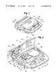
- FIG. 2is a perspective view of the AED of FIG. 1 having the lid opened;
- FIG. 3is a perspective view of a rescue information data card
- FIG. 4is a perspective view of the AED having the rescue information data card being inserted therein according to the present invention.
- FIG. 5is a block diagram of an electrical system of the AED.
- an automated external defibrillator (AED) 10 with the ability to store rescue informationmay be appreciated.
- the stored rescue informationmay include patient data, AED operational data and/or sound.
- AED 10includes a plastic case 12 with a carrying handle 14 on the front portion.
- a battery compartment (not visible) in the rear portion of AED 10is enclosed by a battery pack 16 , the battery pack 16 being removably disposed within the battery compartment.
- Case 12also includes an electrode compartment 26 defined in the top portion of the case 12 .
- An illuminatable resume/rescue switch 18(depicted in FIG. 2) is disposed adjacent to the electrode compartment 26 .
- the electrode compartment 26is enclosed by lid 27 which is mounted to the case 12 by hinges (not visible).
- the lid 27covers the resume/rescue switch 18 when the lid 27 is in the closed disposition, as depicted in FIGS. 1 and 4.
- the resume/rescue switch 18is actually a single switch with illuminatable labels alternatively indicating the “resume” or the “rescue” function, “rescue” appearing above the switch 18 and “resume” appearing below the switch 18 , depending on whether the AED 10 is cuing the operator to perform a rescue or resume operation by activating the switch 18 .
- lid 27incorporates a data card storage clasp 28 for holding a data card 29 (depicted in FIG. 3 ).
- a bayonet-type releasable latch 30holds lid 27 closed when AED 10 is not in use by engaging a receiving recess 31 defined in the floor of the electrode compartment 26 .
- the lid 27is opened by grasping the underside of the latch 30 , pushing in and lifting upward on the latch 30 to gain access to the electrode compartment 26 .
- Electrodes 50are removably connected to electrode connector 32 . Electrodes 50 typically include a pair of electrodes for attachment to a patient in a sealed package.
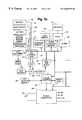
- FIG. 5is a block diagram of the electrical system 70 of AED 10 .
- the overall operation of AED 10is controlled by a digital microprocessor-based control system 72 which includes a processor 74 interfaced to program memory 76 , data memory 77 , event memory 78 and real time clock 79 .
- the operating program executed by processor 74is stored in program memory 76 .
- Data memory 77is used by processor 74 as a scratch pad memory during the execution of the operating program.
- Electrical poweris preferably provided by a lithium sulphur dioxide battery 80 which is enclosed in the battery pack 16 , the battery pack 16 being removably positioned within the battery compartment.
- the battery 80may be comprised of a plurality of battery cells that are electrically coupled together.
- the battery 80is connected to power generation circuit 84 .
- the “Battery Status” indicator light 38will indicate the charge status of the battery 80 and prompt the operator to replace the battery 80 when needed.
- power generation circuit 84During normal operation, power generation circuit 84 generates regulated ⁇ 5V and 12V (actually about 5.4V and 11.6V) supplies with the power provided by the battery 80 .
- the ⁇ 5V output of the battery 80functions as a back-up battery to power components of electrical system 70 during the execution of self-tests and to activate maintenance indicators and alarms (as described below).
- power generation circuit 84includes voltage level sensing circuits which are coupled to processor 74 . The voltage level sensing circuits provide low battery level signals to processor 74 .
- Power generation circuit 84is also connected to power control circuit 88 and processor 74 .
- Power control circuit 88is connected to lid switch 90 , watch dog timer 92 , real time clock 79 and processor 74 .
- Lid switch 90is a magnetic reed relay switch in one embodiment, and provides signals to processor 74 indicating whether lid 27 is open or closed.
- Serial connector port 23is coupled to processor 74 for two-way serial data transfer using an RS-232 protocol.
- Voice circuit 94is connected to the speaker 34 . In response to voice prompt control signals from processor 74 , circuit 94 and speaker 34 generate audible voice prompts.
- High voltage generation circuit 86is also connected to and controlled by processor 74 .
- High voltage generation circuit such as circuit 86are generally known, and disclosed, for example, in the commonly assigned Persson et al., U.S. Pat. No. 5,405,361, which is hereby incorporated by reference.
- high voltage generation circuit 86is operated in a charge mode during which one set of semiconductor switches (not separately shown) cause a plurality of capacitors (also not shown), to be charged in parallel to the 12V potential supplied by power generation circuit 84 .
- high voltage generation circuit 86is operated in a discharge mode during which the capacitors are discharged in series by another set of semiconductor switches (not separately shown) to produce the high voltage defibrillation pulses.
- the defibrillation pulsesare applied to the patient through electrode connector 32 which is connected to the high voltage generation circuit 86 .
- processor 74causes high voltage generation circuit 86 to be discharged through an internal resistive load 98 rather than connector 32 .
- Impedance measuring circuit 100is connected to electrode connector 32 and real time clock 79 , and is interfaced to processor 74 through analog-to-digital (A/D) converter 102 .
- the impedance measuring circuit 100receives a clock signal having a predetermined magnitude from clock 79 , and applies the signal to electrodes 50 through connector 32 .
- the magnitude of the clock signal received back from the electrodes 50 through connector 32is monitored by impedance measuring circuit 100 .
- An impedance signal representative of the impedance present across electrode connector 32is then generated by circuit 100 as a function of the ratio of the magnitudes of the applied and received clock signals (i.e., the attenuation of the applied signal).
- Electrodes 50are not properly connected to connector 32 , or electrodes 50 are not properly positioned on the patient, a relatively high resistance (e.g, greater than about one hundred ohms) will be present across the connector 32 .
- the resistance across connector 32will be between about fifty and eighty ohms when fresh electrodes 50 are properly positioned on the patient with good electrical contacts.
- the impedance signal representative of the impedance measured by circuit 100is digitized by A/D converter 102 and provided to processor 74 .
- AED 10also includes a data recorder 103 that is interfaced to processor 74 and positioned internally within AED 10 adjacent data card slot 24 so as to be ready to accept data card 29 .
- AED 10further includes an electrocardiogram (EKG) filter and amplifier 104 which is connected between electrode connector 32 and A/D converter 102 .
- EKGelectrocardiogram
- the EKG or cardiac rhythm of the patientis processed by filter and amplifier 104 in a conventional manner, and digitized by A/D converter 102 before being coupled to processor 74 .
- the rescue mode operation of AED 10is initiated when an operator opens lid 27 to access the electrodes 50 .
- the opening of the lid 27is detected by lid switch 90 , which effectively functions as an on/off switch.
- power control circuit 88activates power generation circuit 84 and initiates rescue mode operation of processor 74 .
- Processor 74then begins its rescue mode operation by switching maintenance indicator 20 to a maintenance required state (e.g., a yellow visual display in one embodiment), flashing rescue switch light associated with the resume/rescue switch 18 and the indicator lights on diagnostic display panel 36 , and performing a lid opened self-test.
- maintenance required statee.g., a yellow visual display in one embodiment
- processor 74checks: 1) the charge state of battery 80 ; 2) the interconnection and operability of electrodes 50 ; 3) the state of event memory 78 ; 4) the functionality of real time clock 79 ; and 5) the functionality of A/D converter 102 .
- the charge state of battery 80is checked by monitoring the voltage level signals provided by power generation circuit 84 . If battery 80 is determined to have a low charge, the “battery status” indicator on diagnostic display panel 36 will indicate the sensed status.
- the interconnection and operability of the electrodes 50are checked by monitoring the impedance signals provided by impedance measuring circuit 100 . If the electrodes 50 are missing or unplugged from connector 32 , or if the electrodes 50 are damaged, processor 74 will illuminate the “Electrodes” indicator light 40 on diagnostic display panel 36 .
- processor 74accesses the event memory 78 to determine whether data from a previous rescue is still stored in memory. If so, processor 74 causes the “resume” indicator associated with the resume/rescue switch 18 on diagnostic panel 36 to be illuminated, and initiates the generation of a “Press resume button to clear memory and continue” voice prompt. If resume/rescue switch 18 is pressed by the operator following the activation of these indicators, processor 74 clears event memory 78 and proceeds with its rescue mode operation.
- the functionality of real time clock 79 and A/D converter 102are checked by monitoring the outputs of these circuit elements for expected signals. Diagnostic display panel light 38 is illuminated by processor 74 if faults are identified in either of real time clock 79 or A/D converter 102 .
- processor 74switches maintenance indicator 20 to an operational state and initiates the rescue mode of operation of AED 10 .
- the rescue mode of operationgenerates audible voice prompts to guide the user through the operations of AED 10 and if necessary, delivery of a defibrillation pulse.
- the AED 10determines its rescue mode steps of operation by monitoring the impedance across electrode connector 32 and by monitoring the patient's cardiac rhythm.
- the closing of lid 27 after rescue mode operationactivates processor 74 to initiate and perform a lid closed self-test.
- processor 74performs a comprehensive check of the status and functionality of AED 10 , including: 1) the state of event memory 78 , 2) the functionality of real time clock 79 ; 3) the functionality of A/D converter 102 ; 4) the functionality of program memory 76 , data memory 77 and event memory 78 ; 5) the charge state of battery 80 ; and 6) the interconnection and operability of electrodes 50 .
- the state of event memory 78 , the state of battery 80 , the interconnection and operability of electrodes 50 , and the functionality of real time clock 79 and A/D converter 102are checked in a manner identical to that described above with reference to the lid opened self-test.
- a daily self-testis initiated and performed by processor 74 at a predetermined time each day (i.e., every twenty-four hours). During the daily self-test, processor 74 performs all the component check operations described above that are performed during the lid opened and lid closed self-tests. In addition to illuminating the appropriate lights on diagnostic display panel 36 , processor 74 switches maintenance indicator 20 to its maintenance required state if faults are identified during the daily self-test.
- Processor 74also initiates and performs a weekly self-test at a predetermined time one day each week. During the weekly self-test processor 74 performs all the component check operations described above that are performed during the daily self-test. In addition, processor 74 causes high voltage generation circuit 86 to sequentially operate in its charge and discharge modes, with the charge being dumped to an internal resistive load 98 . While the high voltage generation circuit 86 is operating in the charge mode, processor 74 monitors the time required to charge the circuit's capacitors and the capacitor voltage. A fault is identified if either is out of nominal conditions. Maintenance indicator 20 and alarm 96 are actuated in the manner described above if any faults are identified during the weekly self-test. Note that all performed test and patient data may be recorded in event memory 78 .
- Watch dog timer 92is set to time watch dog time-out periods of about thirty hours (i.e., a period greater than twenty-four hour periods between daily self-tests), and is reset by processor 74 at the beginning of each daily self-test and each time lid 27 is opened.
- power control circuit 88causes processor 74 to switch maintenance indicator 20 to the maintenance required state and to actuate alarm 96 to alert an operator to the fact that AED 10 requires maintenance.
- AED 10facilitates archival storage of rescue information in that data representative of the operation of AED 10 , patient data, including the monitored cardiac rhythm of the patient, AED analysis of the patient data, key events detected during the rescue operation, and sound occurring within the immediate vicinity of AED 10 are stored in event memory 78 during rescue mode operation.
- data card 29which is preferably a memory card commonly known as a flashcard, is inserted into card slot 24 before beginning the rescue attempt, the rescue information is automatically recorded by data recorder 103 onto data card 29 thereby also facilitating archival storage of rescue information.
- the data card 29is preferably a memory card having a RAM storage capability of 2, 4, 8, 10, or 15 megs capacity.
- Data card 29is capable of storing up to twenty minutes of rescue information and sound. With data card 29 inserted, the default settings of AED 10 are such that sound is automatically recorded. The sound recording capability may be disabled, however thereby extending the time that rescue information may be recorded on data card 29 up to five hours.
- a voice promptwill be issued that says “Card full. Storing internally.” If upon hearing this prompt, the operator ejects the full data card 29 and inserts an empty data card 29 before placing electrodes 50 on the patient, rescue data will then be stored on the new card 29 . If full card 29 is left in slot 24 when electrodes 50 are placed on the patient, rescue information will then be stored in AED event memory 78 .
- Stored data representative of the operation of AED 10includes the real time of the occurrence of each of the following events: 1) the placement of electrodes 50 on the patient, 2) the initiation of the cardiac rhythm analysis voice prompt, 3) the initiation of the charging voice prompt, 4) the completion of the charge mode operation of high voltage generation circuit 86 , and 5) the actuation of the resume/rescue switch 18 in the rescue mode.
- the actual time base of the patient's cardiac rhythme.g., EKG information, is also stored.
- the stored datacan be retrieved from event memory 78 through the use of a personal computer (PC) 105 interfaced to serial connector port 23 .
- Real time clock 79can also be set through the use of PC 105 interfaced to communications port 22 .
- the datamay also be retrieved through the use of PC 105 interfaced to serial connector port 23 .
- the data card 29may be ejected from AED 10 and inserted into an appropriate card reader 106 that is directly connected to PC 105 , such as a PCMCIA type I card reader.
- the card reading hardware of the AED 10may be used to provide the data card reading function for the PC 105 . This is accomplished by interfacing PC 105 to serial connector port 23 of the AED 10 . This is typically accomplished by connecting a multi-strand wire (not shown) to the PC 105 and the serial connector port 23 . The datacard 29 is then inserted into slot 24 of the AED 10 to establish a communications interface between the datacard 29 and the processor 74 . When this accomplished, the software of the PC 105 can access the information stored on the data card 29 , as the processor 74 configures the AED 10 to provide the card reading function for the PC 105 .
- PC 105may be used to clear event memory 78 and/or data card 29 of previous rescue information when PC 105 is connected to AED 10 through serial connector port 23 .
- the data card reader 106 of PC 105may also be used to clear the memory of data card 29 .
- PC 105may be used to enter additional information to help identify the rescue information. This additional information may include patient name, medical identification, name of the responder who performed the rescue and the serial number of AED 10 .
- PC 105can be used to display all data to the user and to keep logs of performance.
- processor 74Upon the completion of each lid opened, lid closed, daily and weekly self-test, processor 74 causes a record of the self-test to be stored in event memory 78 .
- Each stored recordincludes data representative of the date and time of the test and the results of the test.
- the test resultsare recorded in the form of a code or other description indicating whether all the functions, components and component status states passed the test, or indicating the nature of any identified faults. In one embodiment, only the records of the twenty most recently performed tests are stored in memory 78 .
- the stored self-test recordscan be retrieved from memory 78 through PC 105 interfaced to serial connector port 23 .
- AED 10offers considerable advantages in that it allows recordation and thus, tracking of the operation of AED 10 , of patient data and of actual sound from a rescue event occurring within the immediate vicinity of AED 10 . Such data may be used to evaluate performance of the AED 10 itself as well as the performance of the responder that is using the AED 10 . Further, the information tracking may be used to develop new features for AED 10 and new methods for training users of AED 10 .
Landscapes
- Health & Medical Sciences (AREA)
- Cardiology (AREA)
- Heart & Thoracic Surgery (AREA)
- Engineering & Computer Science (AREA)
- Biomedical Technology (AREA)
- Nuclear Medicine, Radiotherapy & Molecular Imaging (AREA)
- Radiology & Medical Imaging (AREA)
- Life Sciences & Earth Sciences (AREA)
- Animal Behavior & Ethology (AREA)
- General Health & Medical Sciences (AREA)
- Public Health (AREA)
- Veterinary Medicine (AREA)
- Electrotherapy Devices (AREA)
Abstract
Description
Claims (42)
Priority Applications (1)
| Application Number | Priority Date | Filing Date | Title |
|---|---|---|---|
| US09/057,044US6668192B1 (en) | 1997-04-08 | 1998-04-08 | Automated external defibrilator with the ability to store rescue information |
Applications Claiming Priority (2)
| Application Number | Priority Date | Filing Date | Title |
|---|---|---|---|
| US4275597P | 1997-04-08 | 1997-04-08 | |
| US09/057,044US6668192B1 (en) | 1997-04-08 | 1998-04-08 | Automated external defibrilator with the ability to store rescue information |
Publications (1)
| Publication Number | Publication Date |
|---|---|
| US6668192B1true US6668192B1 (en) | 2003-12-23 |
Family
ID=29738649
Family Applications (1)
| Application Number | Title | Priority Date | Filing Date |
|---|---|---|---|
| US09/057,044Expired - LifetimeUS6668192B1 (en) | 1997-04-08 | 1998-04-08 | Automated external defibrilator with the ability to store rescue information |
Country Status (1)
| Country | Link |
|---|---|
| US (1) | US6668192B1 (en) |
Cited By (37)
| Publication number | Priority date | Publication date | Assignee | Title |
|---|---|---|---|---|
| US20040015191A1 (en)* | 2002-05-31 | 2004-01-22 | Otman Alejandro A. | Capturing images of a defibrillation scene |
| US20040019258A1 (en)* | 2002-07-09 | 2004-01-29 | Kavounas Gregory T. | Detecting removal of a medical device from a station |
| US20040049233A1 (en)* | 2002-09-11 | 2004-03-11 | Edwards D. Craig | Medical device status information system |
| US20040115607A1 (en)* | 1999-01-29 | 2004-06-17 | Pastrick John J. | Programmable AED-CPR training device |
| US20040127774A1 (en)* | 2002-12-26 | 2004-07-01 | Moore Mark P. | Communicating medical event information |
| US20040133242A1 (en)* | 2003-01-02 | 2004-07-08 | Chapman Fred W. | Medical device communication |
| US20040172069A1 (en)* | 2003-02-28 | 2004-09-02 | Hakala Douglas T. | Recording information for emergency call by defibrillator apparatus |
| US20040172070A1 (en)* | 2003-02-28 | 2004-09-02 | Moore Mark P. | Annotating an audio recording during a medical emergency |
| US20040204743A1 (en)* | 2003-01-14 | 2004-10-14 | Mcgrath Thomas J. | Remotely operating external medical devices |
| US20050165322A1 (en)* | 2004-01-23 | 2005-07-28 | Bryant Terry K. | Method of improving medical apparatus in order to reduce or replace ancillary medical assistance by employing audible verbal human sounding voices which provide therapeutic instructions and encourage usage and give measurements as needed emanating from the apparatus's by using electronic technology |
| US6937150B2 (en) | 2001-07-31 | 2005-08-30 | Medtronic Physio-Control Manufacturing Corp. | Method and system for locating a portable medical device |
| US6942625B1 (en)* | 2002-05-11 | 2005-09-13 | Terry Keith Bryant | Incentive spirometry devices by the employment of verbal simulated humanlike voices |
| US20060030891A1 (en)* | 1999-05-14 | 2006-02-09 | Medtronic Physio-Control Manufacturing Corp. | Method and apparatus for remote wireless communication with a medical device |
| US20060149321A1 (en)* | 2004-12-30 | 2006-07-06 | Merry Randy L | Medical device information system |
| US20060173498A1 (en)* | 2005-01-31 | 2006-08-03 | Isabelle Banville | Communication between an external defibrillator and an implantable medical device |
| US7120488B2 (en) | 2002-05-07 | 2006-10-10 | Medtronic Physio-Control Manufacturing Corp. | Therapy-delivering portable medical device capable of triggering and communicating with an alarm system |
| US7289029B2 (en) | 2002-12-31 | 2007-10-30 | Medtronic Physio-Control Corp. | Communication between emergency medical device and safety agency |
| US20090054940A1 (en)* | 2005-12-22 | 2009-02-26 | Medtronic, Inc. | Defibrillator with implantable medical device detection |
| US20090240295A1 (en)* | 2005-11-18 | 2009-09-24 | Scientific Pathways International, Llc | Cpr analysis system and method |
| EP2105162A2 (en) | 2008-03-26 | 2009-09-30 | Cardiac Science Corporation | Method and apparatus for defrosting a defibrillation electrode |
| US20090318808A1 (en)* | 2008-05-16 | 2009-12-24 | Brader Eric William | Ultrasound device and system including same |
| US20100023076A1 (en)* | 2006-02-06 | 2010-01-28 | Medtronic Emergency Response Systems, Inc. | Post-download patient data protection in a medical device |
| US20120123242A1 (en)* | 2008-10-27 | 2012-05-17 | Physio-Control, Inc. | External medical device reacting to warning from other medical device about impending independent administration of treatment |
| US20120123241A1 (en)* | 2008-10-27 | 2012-05-17 | Physio-Control, Inc. | External medical device warning other medical device of impending administration of treatment |
| US8666488B2 (en) | 2006-02-06 | 2014-03-04 | Physio-Control, Inc. | Post-download patient data protection in a medical device |
| US8761717B1 (en) | 2012-08-07 | 2014-06-24 | Brian K. Buchheit | Safety feature to disable an electronic device when a wireless implantable medical device (IMD) is proximate |
| USD759249S1 (en)* | 2014-10-30 | 2016-06-14 | The American National Red Cross | Electronic device |
| US20160166349A1 (en)* | 2014-12-11 | 2016-06-16 | Hd1Py, Inc. | Defibrillator storage device |
| US20160235996A1 (en)* | 2015-02-17 | 2016-08-18 | Michael Shane Lloyd | Electrical safety system |
| US20170199797A1 (en)* | 2016-01-08 | 2017-07-13 | Zoll Medical Corporation | Patient assurance system and method |
| US9872998B2 (en) | 2012-05-08 | 2018-01-23 | Physio-Control, Inc. | Defibrillator communication system |
| US10124184B2 (en) | 2003-12-17 | 2018-11-13 | Physio-Control, Inc. | Defibrillator/monitor system having a pod with leads capable of wirelessly communicating |
| US10303852B2 (en) | 2012-07-02 | 2019-05-28 | Physio-Control, Inc. | Decision support tool for use with a medical monitor-defibrillator |
| US10413742B2 (en) | 2008-03-05 | 2019-09-17 | Physio-Control, Inc. | Defibrillator patient monitoring pod |
| US10993626B2 (en) | 2012-06-29 | 2021-05-04 | Zoll Medical Corporation | Rescue scene video transmission |
| US11202569B2 (en) | 2016-03-31 | 2021-12-21 | Zoll Medical Corporation | Remote access for ambulatory medical device |
| US11213211B2 (en) | 2015-03-20 | 2022-01-04 | Zoll Medical Corporation | Systems and methods for testing a medical device |
Citations (4)
| Publication number | Priority date | Publication date | Assignee | Title |
|---|---|---|---|---|
| US4945477A (en) | 1987-10-22 | 1990-07-31 | First Medic | Medical information system |
| US5549115A (en) | 1994-09-28 | 1996-08-27 | Heartstream, Inc. | Method and apparatus for gathering event data using a removable data storage medium and clock |
| US5683423A (en) | 1996-03-14 | 1997-11-04 | Hewlett-Packard Company | Defibrillator and method for storing selected segments of audio data |
| US5716380A (en) | 1996-04-15 | 1998-02-10 | Physio-Control Corporation | Common therapy/data port for a portable defibrillator |
- 1998
- 1998-04-08USUS09/057,044patent/US6668192B1/ennot_activeExpired - Lifetime
Patent Citations (5)
| Publication number | Priority date | Publication date | Assignee | Title |
|---|---|---|---|---|
| US4945477A (en) | 1987-10-22 | 1990-07-31 | First Medic | Medical information system |
| US5549115A (en) | 1994-09-28 | 1996-08-27 | Heartstream, Inc. | Method and apparatus for gathering event data using a removable data storage medium and clock |
| US5680864A (en) | 1994-09-28 | 1997-10-28 | Heartstream, Inc. | Method for processing event data using a removable data storage medium and clock |
| US5683423A (en) | 1996-03-14 | 1997-11-04 | Hewlett-Packard Company | Defibrillator and method for storing selected segments of audio data |
| US5716380A (en) | 1996-04-15 | 1998-02-10 | Physio-Control Corporation | Common therapy/data port for a portable defibrillator |
Non-Patent Citations (1)
| Title |
|---|
| Sur VivaLink AED Automatic External Defibrillator System, SurVivaLink Brochure, Sur VivaLink Corporation, 4 pages, Nov. 1993. |
Cited By (62)
| Publication number | Priority date | Publication date | Assignee | Title |
|---|---|---|---|---|
| US6969259B2 (en)* | 1999-01-29 | 2005-11-29 | Cardiac Science, Inc. | Programmable AED-CPR training device |
| US20040115607A1 (en)* | 1999-01-29 | 2004-06-17 | Pastrick John J. | Programmable AED-CPR training device |
| US20060030891A1 (en)* | 1999-05-14 | 2006-02-09 | Medtronic Physio-Control Manufacturing Corp. | Method and apparatus for remote wireless communication with a medical device |
| US6937150B2 (en) | 2001-07-31 | 2005-08-30 | Medtronic Physio-Control Manufacturing Corp. | Method and system for locating a portable medical device |
| US7120488B2 (en) | 2002-05-07 | 2006-10-10 | Medtronic Physio-Control Manufacturing Corp. | Therapy-delivering portable medical device capable of triggering and communicating with an alarm system |
| US6942625B1 (en)* | 2002-05-11 | 2005-09-13 | Terry Keith Bryant | Incentive spirometry devices by the employment of verbal simulated humanlike voices |
| US20040015191A1 (en)* | 2002-05-31 | 2004-01-22 | Otman Alejandro A. | Capturing images of a defibrillation scene |
| US20040019258A1 (en)* | 2002-07-09 | 2004-01-29 | Kavounas Gregory T. | Detecting removal of a medical device from a station |
| US20040049233A1 (en)* | 2002-09-11 | 2004-03-11 | Edwards D. Craig | Medical device status information system |
| US7231258B2 (en) | 2002-12-26 | 2007-06-12 | Medtronic Physio-Control Corp. | Communicating medical event information |
| US20070233199A1 (en)* | 2002-12-26 | 2007-10-04 | Moore Mark P | Communicating Medical Event Information |
| US20040127774A1 (en)* | 2002-12-26 | 2004-07-01 | Moore Mark P. | Communicating medical event information |
| US7289029B2 (en) | 2002-12-31 | 2007-10-30 | Medtronic Physio-Control Corp. | Communication between emergency medical device and safety agency |
| US20040133242A1 (en)* | 2003-01-02 | 2004-07-08 | Chapman Fred W. | Medical device communication |
| US20040204743A1 (en)* | 2003-01-14 | 2004-10-14 | Mcgrath Thomas J. | Remotely operating external medical devices |
| US20040172070A1 (en)* | 2003-02-28 | 2004-09-02 | Moore Mark P. | Annotating an audio recording during a medical emergency |
| US7245964B2 (en) | 2003-02-28 | 2007-07-17 | Medtronic Physio-Control Corp. | Annotating an audio recording during a medical emergency |
| US20040172069A1 (en)* | 2003-02-28 | 2004-09-02 | Hakala Douglas T. | Recording information for emergency call by defibrillator apparatus |
| US10124184B2 (en) | 2003-12-17 | 2018-11-13 | Physio-Control, Inc. | Defibrillator/monitor system having a pod with leads capable of wirelessly communicating |
| US20050165322A1 (en)* | 2004-01-23 | 2005-07-28 | Bryant Terry K. | Method of improving medical apparatus in order to reduce or replace ancillary medical assistance by employing audible verbal human sounding voices which provide therapeutic instructions and encourage usage and give measurements as needed emanating from the apparatus's by using electronic technology |
| US20060149321A1 (en)* | 2004-12-30 | 2006-07-06 | Merry Randy L | Medical device information system |
| US20060173498A1 (en)* | 2005-01-31 | 2006-08-03 | Isabelle Banville | Communication between an external defibrillator and an implantable medical device |
| US20090240295A1 (en)* | 2005-11-18 | 2009-09-24 | Scientific Pathways International, Llc | Cpr analysis system and method |
| US8600496B2 (en) | 2005-11-18 | 2013-12-03 | Scientific Pathways International, Llc | CPR analysis system and method |
| US20090054940A1 (en)* | 2005-12-22 | 2009-02-26 | Medtronic, Inc. | Defibrillator with implantable medical device detection |
| US9233256B2 (en) | 2005-12-22 | 2016-01-12 | Physio-Control, Inc. | Defibrillator with implantable medical device detection |
| US8548584B2 (en) | 2005-12-22 | 2013-10-01 | Physio-Control, Inc. | Defibrillator with implantable medical device detection |
| US20100023076A1 (en)* | 2006-02-06 | 2010-01-28 | Medtronic Emergency Response Systems, Inc. | Post-download patient data protection in a medical device |
| US8666488B2 (en) | 2006-02-06 | 2014-03-04 | Physio-Control, Inc. | Post-download patient data protection in a medical device |
| US8532764B2 (en) | 2006-02-06 | 2013-09-10 | Physio-Control, Inc. | Post-download patient data protection in a medical device |
| US10413742B2 (en) | 2008-03-05 | 2019-09-17 | Physio-Control, Inc. | Defibrillator patient monitoring pod |
| US8260414B2 (en) | 2008-03-26 | 2012-09-04 | Cardiac Science Corporation | Method and apparatus for defrosting a defibrillation electrode |
| US20110106192A1 (en)* | 2008-03-26 | 2011-05-05 | Nassif Rabih C | Method and apparatus for defrosting a defibrillation electrode |
| EP2105162A2 (en) | 2008-03-26 | 2009-09-30 | Cardiac Science Corporation | Method and apparatus for defrosting a defibrillation electrode |
| US7881785B2 (en) | 2008-03-26 | 2011-02-01 | Cardiac Science Corporation | Method and apparatus for defrosting a defibrillation electrode |
| US20090318808A1 (en)* | 2008-05-16 | 2009-12-24 | Brader Eric William | Ultrasound device and system including same |
| US20120123242A1 (en)* | 2008-10-27 | 2012-05-17 | Physio-Control, Inc. | External medical device reacting to warning from other medical device about impending independent administration of treatment |
| US20120123241A1 (en)* | 2008-10-27 | 2012-05-17 | Physio-Control, Inc. | External medical device warning other medical device of impending administration of treatment |
| US10926099B2 (en) | 2012-05-08 | 2021-02-23 | Physio-Control, Inc. | Utility module interface |
| US10105546B2 (en) | 2012-05-08 | 2018-10-23 | Physio-Control, Inc. | Utility module |
| US10159846B2 (en) | 2012-05-08 | 2018-12-25 | Physio-Control, Inc. | Utility module interface |
| US10124181B2 (en) | 2012-05-08 | 2018-11-13 | Physio-Control., Inc. | Defibrillator network system |
| US9872998B2 (en) | 2012-05-08 | 2018-01-23 | Physio-Control, Inc. | Defibrillator communication system |
| US10118048B2 (en) | 2012-05-08 | 2018-11-06 | Physio-Control, Inc. | Utility module system |
| US10993626B2 (en) | 2012-06-29 | 2021-05-04 | Zoll Medical Corporation | Rescue scene video transmission |
| US12336790B2 (en) | 2012-06-29 | 2025-06-24 | Zoll Medical Corporation | Rescue scene video transmission |
| US10303852B2 (en) | 2012-07-02 | 2019-05-28 | Physio-Control, Inc. | Decision support tool for use with a medical monitor-defibrillator |
| US8761717B1 (en) | 2012-08-07 | 2014-06-24 | Brian K. Buchheit | Safety feature to disable an electronic device when a wireless implantable medical device (IMD) is proximate |
| US8954030B1 (en) | 2012-08-07 | 2015-02-10 | Brian K. Buchheit | Safety feature to disable an electronic device when a wireless implantable medical device (IMD) is proximate |
| USD759249S1 (en)* | 2014-10-30 | 2016-06-14 | The American National Red Cross | Electronic device |
| US20160166349A1 (en)* | 2014-12-11 | 2016-06-16 | Hd1Py, Inc. | Defibrillator storage device |
| US10485622B2 (en) | 2014-12-11 | 2019-11-26 | Hdipy, Inc. | Defibrillator storage device |
| US10080619B2 (en)* | 2014-12-11 | 2018-09-25 | Hd1Py, Inc. | Defibrillator storage device |
| US10363427B2 (en)* | 2015-02-17 | 2019-07-30 | Michael Shane Lloyd | Electrical safety system |
| US20160235996A1 (en)* | 2015-02-17 | 2016-08-18 | Michael Shane Lloyd | Electrical safety system |
| US11213211B2 (en) | 2015-03-20 | 2022-01-04 | Zoll Medical Corporation | Systems and methods for testing a medical device |
| US11701006B2 (en) | 2015-03-20 | 2023-07-18 | Zoll Medical Corporation | Systems and methods for testing a medical device |
| US12251199B2 (en) | 2015-03-20 | 2025-03-18 | Zoll Medical Corporation | Systems and methods for testing a medical device |
| US11709747B2 (en)* | 2016-01-08 | 2023-07-25 | Zoll Medical Corporation | Patient assurance system and method |
| US20170199797A1 (en)* | 2016-01-08 | 2017-07-13 | Zoll Medical Corporation | Patient assurance system and method |
| US11202569B2 (en) | 2016-03-31 | 2021-12-21 | Zoll Medical Corporation | Remote access for ambulatory medical device |
| US12109004B2 (en) | 2016-03-31 | 2024-10-08 | Zoll Medical Corporation | Remote access for ambulatory medical device |
Similar Documents
| Publication | Publication Date | Title |
|---|---|---|
| US6668192B1 (en) | Automated external defibrilator with the ability to store rescue information | |
| US5797969A (en) | One button lid activated automatic external defibrillator | |
| US5645571A (en) | Automated external defibrillator with lid activated self-test system | |
| US5868794A (en) | AED and battery pack with anticipatory battery disengagement detection | |
| US6366809B1 (en) | Defibrillator battery with memory and status indication guage | |
| US6125298A (en) | Defibrillation system for pediatric patients | |
| US6083246A (en) | Lid open detection circuit for automated external defibrillators | |
| US5897576A (en) | Automated external defibrillator with the ability to sense temperature | |
| US5955956A (en) | Audible alarm system for an automated external defibrillator | |
| US9008767B2 (en) | System and method for performing self-test in an automatic external defribillator (AED) | |
| US8494628B2 (en) | Automatic external defibrillator with active status indicator | |
| US5662690A (en) | Defibrillator with training features and pause actuator | |
| US5683423A (en) | Defibrillator and method for storing selected segments of audio data | |
| US6088616A (en) | Field programmable automated external defibrillator | |
| US5697955A (en) | Defibrillator electrodes and date code detector circuit | |
| EP0757912B1 (en) | Automated external defibrillator with self-test system | |
| WO1997043000A1 (en) | Defibrillator electrode circuitry | |
| EP1637181A1 (en) | Automated external defibrillator | |
| EP1419798A2 (en) | Automated external defibrillator | |
| EP1370327B1 (en) | Battery pack for an automatic external defibrillator | |
| WO1998044989A1 (en) | Automated external defibrillator battery memory, dual cell, and removable configurations | |
| WO1998044988A1 (en) | Field programmable automated external defibrillator | |
| HK1067565A (en) | Automated external defibrillator | |
| Supino | The system |
Legal Events
| Date | Code | Title | Description |
|---|---|---|---|
| AS | Assignment | Owner name:SURVIVALINK CORPORATION, MINNESOTA Free format text:ASSIGNMENT OF ASSIGNORS INTEREST;ASSIGNORS:PARKER, WILLIAM S.;OLSON, KENNETH F.;TVEDT, MICHAEL A.;REEL/FRAME:009094/0221 Effective date:19980408 Owner name:SURVIVALINK CORPORATION, MINNESOTA Free format text:ASSIGNMENT OF ASSIGNORS INTEREST;ASSIGNORS:PARKER, WILLIAM S.;OLSON, KENNETH F.;TVEDT, MICHAEL A.;REEL/FRAME:009382/0616 Effective date:19980408 | |
| AS | Assignment | Owner name:HSBC BANK, USA, NEW YORK Free format text:SECURITY AGREEMENT;ASSIGNOR:CARDIAC SCIENCE, INC.;REEL/FRAME:013146/0001 Effective date:20020530 | |
| AS | Assignment | Owner name:CARDIAC SCIENCE, INC., MINNESOTA Free format text:ASSIGNMENT OF ASSIGNORS INTEREST;ASSIGNOR:SURVIVALINK CORPORATION;REEL/FRAME:013280/0068 Effective date:20020718 | |
| STCF | Information on status: patent grant | Free format text:PATENTED CASE | |
| AS | Assignment | Owner name:CARDIAC SCIENCE CORPORATION, WASHINGTON Free format text:MERGER;ASSIGNOR:CARDIAC SCIENCE, INC.;REEL/FRAME:018268/0816 Effective date:20060224 | |
| FPAY | Fee payment | Year of fee payment:4 | |
| AS | Assignment | Owner name:SILICON VALLEY BANK,CALIFORNIA Free format text:SECURITY AGREEMENT;ASSIGNOR:CARDIAC SCIENCE, INC.;REEL/FRAME:024492/0931 Effective date:20100607 Owner name:SILICON VALLEY BANK, CALIFORNIA Free format text:SECURITY AGREEMENT;ASSIGNOR:CARDIAC SCIENCE, INC.;REEL/FRAME:024492/0931 Effective date:20100607 | |
| FPAY | Fee payment | Year of fee payment:8 | |
| AS | Assignment | Owner name:CARDIAC SCIENCE CORPORATION, WASHINGTON Free format text:RELEASE BY SECURED PARTY;ASSIGNOR:SILICON VALLEY BANK;REEL/FRAME:029389/0937 Effective date:20121012 | |
| AS | Assignment | Owner name:DBS BANK LTD., BANGALORE BRANCH, INDIA Free format text:SECURITY AGREEMENT;ASSIGNOR:CARDIAC SCIENCE CORPORATION;REEL/FRAME:029733/0363 Effective date:20121228 | |
| FEPP | Fee payment procedure | Free format text:PAT HOLDER NO LONGER CLAIMS SMALL ENTITY STATUS, ENTITY STATUS SET TO UNDISCOUNTED (ORIGINAL EVENT CODE: STOL); ENTITY STATUS OF PATENT OWNER: LARGE ENTITY | |
| FEPP | Fee payment procedure | Free format text:PAYOR NUMBER ASSIGNED (ORIGINAL EVENT CODE: ASPN); ENTITY STATUS OF PATENT OWNER: LARGE ENTITY | |
| FPAY | Fee payment | Year of fee payment:12 | |
| SULP | Surcharge for late payment | ||
| AS | Assignment | Owner name:CFS 915 LLC, AS SECURITY TRUSTEE AND SECURITY AGEN Free format text:ASSIGNMENT OF INTELLECTUAL PROPERTY SECURITY AGREEMENT;ASSIGNOR:DBS BANK LTD, BANGALORE BRANCH;REEL/FRAME:036712/0001 Effective date:20150929 | |
| AS | Assignment | Owner name:CARD-SCI INC., CALIFORNIA Free format text:ASSIGNMENT OF ASSIGNORS INTEREST;ASSIGNOR:CARDIAC SCIENCE CORPORATION;REEL/FRAME:037627/0418 Effective date:20160125 | |
| AS | Assignment | Owner name:THE PRIVATEBANK AND TRUST COMPANY, ILLINOIS Free format text:SECURITY INTEREST;ASSIGNOR:CARD-SCI INC.;REEL/FRAME:037689/0592 Effective date:20160125 | |
| AS | Assignment | Owner name:CARD-SCI INC., CALIFORNIA Free format text:CORRECTIVE ASSIGNMENT TO CORRECT THE PATENT NO. 6143233 THAT WAS INCORRECTLY ASSIGNED PREVIOUSLY RECORDED ON REEL 037627 FRAME 0418. ASSIGNOR(S) HEREBY CONFIRMS THE THE CORRECT PATENT NUMBER IS 6148233;ASSIGNOR:CARDIAC SCIENCE CORPORATION;REEL/FRAME:037783/0215 Effective date:20160125 Owner name:CARDIAC SCIENCE CORPORATION, WISCONSIN Free format text:CHANGE OF NAME;ASSIGNOR:CARD-SCI INC.;REEL/FRAME:037793/0106 Effective date:20160126 | |
| AS | Assignment | Owner name:CARDIAC SCIENCE CORPORATION, WISCONSIN Free format text:CHANGE OF NAME;ASSIGNOR:CARD-SCI INC.;REEL/FRAME:037897/0952 Effective date:20160126 | |
| AS | Assignment | Owner name:CARDIAC SCIENCE CORPORATION, WISCONSIN Free format text:RELEASE BY SECURED PARTY;ASSIGNOR:CIBC BANK USA (FKA THE PRIVATEBANK AND TRUST COMPANY);REEL/FRAME:050300/0804 Effective date:20190826 | |
| AS | Assignment | Owner name:ZOLL MEDICAL CORPORATION, MASSACHUSETTS Free format text:ASSIGNMENT OF ASSIGNORS INTEREST;ASSIGNOR:CARDIAC SCIENCE CORPORATION;REEL/FRAME:056391/0439 Effective date:20210409 |