US6668168B1 - Radio communication system - Google Patents
Radio communication systemDownload PDFInfo
- Publication number
- US6668168B1 US6668168B1US09/478,468US47846800AUS6668168B1US 6668168 B1US6668168 B1US 6668168B1US 47846800 AUS47846800 AUS 47846800AUS 6668168 B1US6668168 B1US 6668168B1
- Authority
- US
- United States
- Prior art keywords
- channel
- control channel
- data
- uplink
- control information
- Prior art date
- Legal status (The legal status is an assumption and is not a legal conclusion. Google has not performed a legal analysis and makes no representation as to the accuracy of the status listed.)
- Expired - Lifetime
Links
Images


Classifications
- H—ELECTRICITY
- H04—ELECTRIC COMMUNICATION TECHNIQUE
- H04W—WIRELESS COMMUNICATION NETWORKS
- H04W28/00—Network traffic management; Network resource management
- H04W28/02—Traffic management, e.g. flow control or congestion control
- H04W28/06—Optimizing the usage of the radio link, e.g. header compression, information sizing, discarding information
- H—ELECTRICITY
- H04—ELECTRIC COMMUNICATION TECHNIQUE
- H04W—WIRELESS COMMUNICATION NETWORKS
- H04W72/00—Local resource management
- H04W72/04—Wireless resource allocation
- H04W72/044—Wireless resource allocation based on the type of the allocated resource
- H04W72/0446—Resources in time domain, e.g. slots or frames
- H—ELECTRICITY
- H04—ELECTRIC COMMUNICATION TECHNIQUE
- H04W—WIRELESS COMMUNICATION NETWORKS
- H04W72/00—Local resource management
- H04W72/20—Control channels or signalling for resource management
- H—ELECTRICITY
- H04—ELECTRIC COMMUNICATION TECHNIQUE
- H04W—WIRELESS COMMUNICATION NETWORKS
- H04W72/00—Local resource management
- H04W72/20—Control channels or signalling for resource management
- H04W72/21—Control channels or signalling for resource management in the uplink direction of a wireless link, i.e. towards the network
- H—ELECTRICITY
- H04—ELECTRIC COMMUNICATION TECHNIQUE
- H04W—WIRELESS COMMUNICATION NETWORKS
- H04W72/00—Local resource management
- H04W72/20—Control channels or signalling for resource management
- H04W72/23—Control channels or signalling for resource management in the downlink direction of a wireless link, i.e. towards a terminal
- H—ELECTRICITY
- H04—ELECTRIC COMMUNICATION TECHNIQUE
- H04W—WIRELESS COMMUNICATION NETWORKS
- H04W28/00—Network traffic management; Network resource management
- H04W28/02—Traffic management, e.g. flow control or congestion control
- H04W28/10—Flow control between communication endpoints
- H—ELECTRICITY
- H04—ELECTRIC COMMUNICATION TECHNIQUE
- H04W—WIRELESS COMMUNICATION NETWORKS
- H04W52/00—Power management, e.g. Transmission Power Control [TPC] or power classes
- H04W52/04—Transmission power control [TPC]
- H04W52/06—TPC algorithms
- H04W52/08—Closed loop power control
- H—ELECTRICITY
- H04—ELECTRIC COMMUNICATION TECHNIQUE
- H04W—WIRELESS COMMUNICATION NETWORKS
- H04W52/00—Power management, e.g. Transmission Power Control [TPC] or power classes
- H04W52/04—Transmission power control [TPC]
- H04W52/30—Transmission power control [TPC] using constraints in the total amount of available transmission power
- H04W52/36—Transmission power control [TPC] using constraints in the total amount of available transmission power with a discrete range or set of values, e.g. step size, ramping or offsets
- H04W52/362—Aspects of the step size
- H—ELECTRICITY
- H04—ELECTRIC COMMUNICATION TECHNIQUE
- H04W—WIRELESS COMMUNICATION NETWORKS
- H04W76/00—Connection management
- H04W76/20—Manipulation of established connections
- H04W76/28—Discontinuous transmission [DTX]; Discontinuous reception [DRX]
Definitions
- the present inventionrelates to a radio communication system and further relates to primary and secondary stations for use in such a system and to a method of operating such a system. While the present specification describes a system with particular reference to the emerging Universal Mobile Telecommunication System (UMTS), it is to be understood that such techniques are equally applicable to use in other mobile radio systems.
- UMTSUniversal Mobile Telecommunication System
- the firstis user traffic, for example speech or packet data.
- the secondis control information, required to set and monitor various parameters of the transmission channel to enable the BS and MS to exchange the required user traffic.
- UMTS control channelsare maintained in both directions between BS and MS once a connection has been established. This is only a relatively small overhead when speech data is being transmitted. However, in the case of packet data having a low duty cycle (i.e. intermittent transmission of packets using only a small proportion of the available channel capacity), the maintenance of bidirectional control channels represents a significant overhead.
- An object of the present inventionis to reduce the overhead imposed by maintaining control channels for a connection transferring data having a low duty cycle.
- a radio communication systemcomprising a primary station and a plurality of secondary stations, the system having a communication channel between the primary station and a secondary station, the channel comprising an uplink and a downlink control channel for the transmission of control information, and a data channel for the transmission of data packets, characterised in that the primary and secondary stations have traffic reduction means for reducing traffic in the uplink and downlink control channels, and control means for activating the traffic reduction means.
- a primary stationfor use in a radio communication system having a communication channel between the primary station and a secondary station, the channel comprising an uplink and a downlink control channel for the transmission of control information, and a data channel for the transmission of data packets, characterised in that traffic reduction means are provided for reducing traffic in the downlink control channel, and control means are provided for activating the traffic reduction means.
- a secondary stationfor use in a radio communication system having a communication channel between the secondary station and a primary station, the channel comprising an uplink and a downlink control channel for the transmission of control information, and a data channel for the transmission of data packets, characterised in that traffic reduction means are provided for reducing traffic in the uplink control channel, and control means are provided for activating the traffic reduction means.
- a radio communication systemcomprising a primary station and a plurality of secondary stations, the system having a communication channel between the primary station and a secondary station, the channel comprising an uplink and a downlink control channel for the transmission of control information, and a data channel for the transmission of data packets, characterised by the primary and secondary stations being able to reduce traffic in the uplink and downlink control channels.
- FIG. 1is a block schematic diagram of a radio communication system
- FIG. 2illustrates a conventional scheme for the transmission of packet data
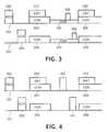
- FIG. 3illustrates a scheme in accordance with the present invention for the transmission of packet data with a control channel having a dormant state in which traffic on the control channel is reduced;
- FIG. 4illustrates a scheme in accordance with the present invention for the transmission of packet data with an interruptible control channel
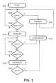
- FIG. 5is a flow chart illustrating a method in accordance with the present invention for utilising a control channel having dormant and interrupted states.
- a radio communication systemwhich can operate in a frequency division duplex mode comprises a primary station (BS) 100 and a plurality of secondary stations (MS) 110 .
- the BS 100comprises a microcontroller ( ⁇ C) 102 , transceiver means (Tx/Rx) 104 connected to radio transmission means 106 , power control means (PC) 107 for altering the transmitted power level, and connection means 108 for connection to the PSTN or other suitable network.
- Each MS 110comprises a microcontroller ( ⁇ C) 112 , transceiver means (Tx/Rx) 114 connected to radio transmission means 116 , and power control means (PC) 118 for altering the transmitted power level.
- Communication from BS 100 to MS 110takes place on a downlink frequency channel 122
- communication from MS 110 to BS 100takes place on an uplink frequency channel 124 .
- Embodiments of the present inventionwill be described using spread spectrum Code Division Multiple Access (CDMA) techniques, as used for example in UMTS embodiments. However, it should be understood that the invention is not limited to use in CDMA systems.
- CDMACode Division Multiple Access
- One UMTS embodiment, the frequency division duplex modeuses the scheme of FIG. 2 for a communication link between MS 110 and BS 100 .
- the linkis initiated by the MS 110 transmitting a request 202 (REQ) for resources on the uplink channel 124 . If it receives the request and has available resources, the BS 100 transmits an acknowledgement 204 (ACK) on the downlink channel 122 providing the necessary information for communication to be established. After the acknowledgement 204 has been sent, two control channels (CON) are established, an uplink control channel 206 and a downlink control channel 208 .
- REQrequest 202
- REQrequest 202
- the BS 100transmits an acknowledgement 204 (ACK) on the downlink channel 122 providing the necessary information for communication to be established.
- ACKacknowledgement 204
- CONtwo control channels
- the control channels 206 , 208include pilot, power control and rate information.
- the pilot informationis primarily provided to allow the receiver to estimate the channel impulse response, in order to optimise detection of the received data (i.e. other information in the control channel and a data packet if present).
- Power control of the uplink channel 124is required so that the BS 100 receives signals from different MS 110 at approximately the same power level, while minimising the transmission power required by each MS 110 .
- Power control of the downlink channel 122is required so that the MS 110 receives signals from the BS 100 with a low error rate while minimising transmission power, to reduce interference with other cells and radio systems.
- Rate informationprovides details of the rate and transmission format of data, to enable the transceivers 104 , 114 to be appropriately configured.
- the MS 110transmits data packets 210 (DAT) with lengthy periods between them, during which periods significant resources are being used on both the uplink 124 and downlink 122 channels just to maintain control channels 206 , 208 .
- DATdata packets 210
- a typical duration for a data packet 210 in a UMTS systemwould be one frame (10ms).
- FIG. 3An improved scheme for low duty cycle traffic, in accordance with the present invention, is shown in FIG. 3 .
- Initiation of the linkproceeds in the same manner as described above in relation to FIG. 2 .
- the uplink 206 and downlink 208 control channelsenter a dormant state 302 , 304 (DOR) between transmission of data packets 210 .
- the dormant statemight for example be entered after a time-out period, or immediately after transmission of a data packet if the transmitting station can determine that no further data packets are currently available for transmission
- the MS 110When the MS 110 has another data packet 210 to send it transmits a re-activation request 306 as part of the dormant channel (or uses alternative signalling means such as a dedicated fast signalling channel).
- a re-activation request 306as part of the dormant channel (or uses alternative signalling means such as a dedicated fast signalling channel).
- the normal control channels 206 , 208are re-activated and the data packet 210 can be transmitted.
- a scheme similar to that described abovecould also be used for continuous transmission of data.
- a channel that is normally used for high data rate transmissionsIf this channel becomes used for transmission of data at a low data rate, the optimum rate of transmission of power control information might also be reduced. Hence, while the data continues at a low rate, the quantity of control information could be reduced in the same way as above.
- FIG. 4An alternative scheme, in which the control channel is interrupted completely, for example after a suitable time-out period, is shown in FIG. 4 .
- This schemecompletely removes the overhead of the control channels 206 , 208 between transmission of data packets 210 .
- re-activation of the control channels 206 , 208can be done with specific signalling. This is illustrated as a re-activation request 402 from the MS 110 , transmitted for example on a dedicated fast signalling channel, followed by an acknowledgement 404 by the BS, after which the control channels 206 , 208 are re-established and data packets 210 can be transmitted.
- the BS 100could reactivate the channel by simply starting to transmit it again, which transmission would be detected by the MS 110 which could then begin transmission of the uplink control channel 206 .
- the MS 110could request re-activation by starting transmission of the uplink control channel 206 .
- the same approachcould also be used for re-activation from the dormant state.
- control channels 206 , 208may be transmitted with a different spreading factor to the data transmissions 210 .
- satisfactory quality estimates for use in power controlmight not be able to be derived accurately from the control channels 206 , 208 alone, and complete interruption of them would not have any additional impact on power control.
- dormant and interrupted control channelsmay be combined.
- a method of using dormant and interrupted control channels for the transmission of data packetsis shown as a flow chart in FIG. 5 .
- the methodstarts at 502 with the establishment of a communication link between the MS 110 and BS 100 .
- the MS 110determines at 504 whether it has any data packets 210 to transmit. If it has they are transmitted 506 . When no more data packets 210 remain to be transmitted the MS 110 determines at 508 whether a first time-out period since transmission of the last data packet 210 has been reached. If it has, the control channels 206 , 208 enter their dormant state at 510 .
- the MS 110checks, at 512 , whether any data packets 210 are waiting for transmission. If any are waiting, the control channels 206 , 208 are re-established at 516 , and the data packets are transmitted 506 . If there are no waiting data packets 210 , the MS 110 determines at 514 whether a second time-out period since transmission of the last data packet 210 has been reached. If it has, transmission of the dormant control channels 302 , 304 is interrupted. The MS 110 then waits at 520 until one or more data packets 210 are waiting for transmission, when it re-establishes the control channels at 516 and transmits the data packets at 506 .
- the time-out periodsshould preferably be chosen to be short enough to save resources, but not so short that frequent transitions between normal, dormant and interrupted states are needed.
- a suitable choicecould be between 5 and 10 frames for the first time-out 508 , and a similar period for the second time-out 514 .
- the present inventionis not restricted to use in a frequency division duplex system. All that is required is for uplink and downlink communication paths to be available. It could, for example, be used in a time division duplex system, although the power control rate in such a system would normally be limited to once per transmission burst.
Landscapes
- Engineering & Computer Science (AREA)
- Computer Networks & Wireless Communication (AREA)
- Signal Processing (AREA)
- Mobile Radio Communication Systems (AREA)
- Time-Division Multiplex Systems (AREA)
- Small-Scale Networks (AREA)
Abstract
Description
Claims (15)
Priority Applications (1)
| Application Number | Priority Date | Filing Date | Title |
|---|---|---|---|
| US10/694,555US7127247B2 (en) | 1999-01-16 | 2003-10-27 | Radio communication system |
Applications Claiming Priority (2)
| Application Number | Priority Date | Filing Date | Title |
|---|---|---|---|
| GB9900909 | 1999-01-16 | ||
| GB9900909 | 1999-01-16 |
Related Child Applications (1)
| Application Number | Title | Priority Date | Filing Date |
|---|---|---|---|
| US10/694,555ContinuationUS7127247B2 (en) | 1999-01-16 | 2003-10-27 | Radio communication system |
Publications (1)
| Publication Number | Publication Date |
|---|---|
| US6668168B1true US6668168B1 (en) | 2003-12-23 |
Family
ID=10845978
Family Applications (2)
| Application Number | Title | Priority Date | Filing Date |
|---|---|---|---|
| US09/478,468Expired - LifetimeUS6668168B1 (en) | 1999-01-16 | 2000-01-06 | Radio communication system |
| US10/694,555Expired - LifetimeUS7127247B2 (en) | 1999-01-16 | 2003-10-27 | Radio communication system |
Family Applications After (1)
| Application Number | Title | Priority Date | Filing Date |
|---|---|---|---|
| US10/694,555Expired - LifetimeUS7127247B2 (en) | 1999-01-16 | 2003-10-27 | Radio communication system |
Country Status (8)
| Country | Link |
|---|---|
| US (2) | US6668168B1 (en) |
| EP (1) | EP1062830B1 (en) |
| JP (1) | JP4637364B2 (en) |
| KR (1) | KR100888033B1 (en) |
| CN (1) | CN1160992C (en) |
| DE (1) | DE69932707T2 (en) |
| TW (1) | TW459461B (en) |
| WO (1) | WO2000042804A1 (en) |
Cited By (7)
| Publication number | Priority date | Publication date | Assignee | Title |
|---|---|---|---|---|
| US20040042508A1 (en)* | 2000-07-14 | 2004-03-04 | Christian Menzel | Method for rapidly allocating radio resources to logical channels in a down-link direction |
| US20040087306A1 (en)* | 1999-01-16 | 2004-05-06 | Moulsley Timothy J. | Radio communication system |
| US20050215257A1 (en)* | 2002-10-03 | 2005-09-29 | Evolium S.A.S. | Method and device for managing radio link interruption in a radio communication shadow zone |
| US20070070926A1 (en)* | 2005-09-29 | 2007-03-29 | Bachl Rainer W | Method of increasing the capacity of enhanced data channel on uplink in a wireless communications system |
| US20090067405A1 (en)* | 2001-06-27 | 2009-03-12 | Nortel Networks Limited | Communication of control information in wireless communication systems |
| US20100091713A1 (en)* | 2007-05-02 | 2010-04-15 | Nec Corporation | Method of transmitting control information |
| US9730214B2 (en) | 2007-08-13 | 2017-08-08 | Interdigital Technology Corporation | Method and apparatus to reduce radio resource overhead associated with intermittent traffic |
Families Citing this family (17)
| Publication number | Priority date | Publication date | Assignee | Title |
|---|---|---|---|---|
| US7184426B2 (en) | 2002-12-12 | 2007-02-27 | Qualcomm, Incorporated | Method and apparatus for burst pilot for a time division multiplex system |
| US9118387B2 (en) | 1997-11-03 | 2015-08-25 | Qualcomm Incorporated | Pilot reference transmission for a wireless communication system |
| US7068683B1 (en) | 2000-10-25 | 2006-06-27 | Qualcomm, Incorporated | Method and apparatus for high rate packet data and low delay data transmissions |
| US6973098B1 (en) | 2000-10-25 | 2005-12-06 | Qualcomm, Incorporated | Method and apparatus for determining a data rate in a high rate packet data wireless communications system |
| GB0108381D0 (en) | 2001-04-04 | 2001-05-23 | Koninl Philips Electronics Nv | Radio communication system |
| KR100689477B1 (en)* | 2003-04-30 | 2007-03-02 | 삼성전자주식회사 | Rapid call setup method and system in wireless communication system |
| US7363010B2 (en)* | 2004-04-15 | 2008-04-22 | Qualcomm Incorporated | Power control for intermittently active data channels in a wireless communication system |
| US20050265373A1 (en)* | 2004-05-28 | 2005-12-01 | Khan Farooq U | Method of reducing overhead in data packet communication |
| JP4516880B2 (en) | 2005-03-29 | 2010-08-04 | 株式会社エヌ・ティ・ティ・ドコモ | Transmission rate control method, mobile station and radio base station |
| US20060245370A1 (en)* | 2005-04-27 | 2006-11-02 | Murali Ranganathan | Method of quality of service reduction |
| JP4643354B2 (en)* | 2005-05-02 | 2011-03-02 | 株式会社エヌ・ティ・ティ・ドコモ | Transmission rate control method, mobile station and radio base station |
| WO2007023000A1 (en)* | 2005-08-26 | 2007-03-01 | Nokia Siemens Networks Gmbh & Co. Kg | Method for controlling the interruption of transmissions for reducing interference in a radio communication system |
| JP4883180B2 (en)* | 2007-07-24 | 2012-02-22 | 富士通株式会社 | Communication system and individual control information transmission / reception method |
| KR20100132427A (en)* | 2009-06-09 | 2010-12-17 | 엘지전자 주식회사 | Low load mode operation method of femto base station |
| WO2011025295A2 (en)* | 2009-08-27 | 2011-03-03 | Samsung Electronics Co., Ltd. | Method and system for efficient support low duty mode in femtocells |
| US9445410B2 (en) | 2012-08-03 | 2016-09-13 | Qualcomm Incorporated | Communicating with an enhanced new carrier type |
| JP6642565B2 (en)* | 2015-03-04 | 2020-02-05 | 日本電気株式会社 | Communication control device, communication system, communication control method, and program |
Citations (13)
| Publication number | Priority date | Publication date | Assignee | Title |
|---|---|---|---|---|
| US4679244A (en)* | 1984-02-29 | 1987-07-07 | Nippon Telegraph & Telephone Public Corporation | Method of transmitting terminating call signals within a restricted duration and a base station and a portable unit for use in the same |
| US5230083A (en)* | 1992-01-30 | 1993-07-20 | Motorola, Inc. | Method for reducing control channel traffic in a communication system |
| US5313655A (en) | 1992-01-30 | 1994-05-17 | Motorola, Inc. | Method for reducing control channel activity for limited audience communications |
| US5745695A (en)* | 1996-01-16 | 1998-04-28 | Motorola Inc. | Radio system with suspension of packet data service during non-data service connection |
| EP0928119A2 (en) | 1998-01-05 | 1999-07-07 | Nokia Mobile Phones Ltd. | Method for using effectively the broadcast capacity in a cell |
| US5946356A (en)* | 1997-07-16 | 1999-08-31 | Motorola, Inc. | Method and apparatus for data transmission within a broad-band communications system |
| US6009325A (en)* | 1995-02-01 | 1999-12-28 | Motorola, Inc. | Method of and apparatus for operating a cellular phone in one of two modes |
| US6052385A (en)* | 1995-12-18 | 2000-04-18 | Nokia Telecommunications Oy | Multichannel high-speed data transfer |
| US6137789A (en)* | 1997-06-26 | 2000-10-24 | Nokia Mobile Phones Limited | Mobile station employing selective discontinuous transmission for high speed data services in CDMA multi-channel reverse link configuration |
| US6272352B1 (en)* | 1997-10-28 | 2001-08-07 | Telefonaktiebolaget Lm Ericsson (Publ) | Methods for determining a number of control channels in a cell |
| US6377809B1 (en)* | 1997-09-16 | 2002-04-23 | Qualcomm Incorporated | Channel structure for communication systems |
| US6456604B1 (en)* | 1998-01-24 | 2002-09-24 | Samsung Electronics, Co., Ltd. | Data communication method in mobile communication system |
| US6473419B1 (en)* | 1998-03-26 | 2002-10-29 | Nokia Corporation | State apparatus, and associated methods, for controlling packet data communications in a radio communication system |
Family Cites Families (9)
| Publication number | Priority date | Publication date | Assignee | Title |
|---|---|---|---|---|
| FI97517C (en)* | 1993-09-06 | 1996-12-27 | Nokia Mobile Phones Ltd | Transmission of packet data in a digital cellular network |
| JPH07303275A (en)* | 1994-05-09 | 1995-11-14 | Matsushita Electric Ind Co Ltd | Mobile communication system |
| JPH0955764A (en)* | 1995-08-14 | 1997-02-25 | Nippon Telegr & Teleph Corp <Ntt> | Wireless packet communication method |
| KR100269880B1 (en)* | 1996-03-15 | 2000-10-16 | 다치카와 게이지 | Mobile communication system and method |
| KR100289568B1 (en)* | 1996-07-29 | 2001-05-02 | 다치카와 게이지 | Method and apparatus for controlling downlink transmission power in mobile communication system using site diversity |
| US6510145B1 (en)* | 1997-07-25 | 2003-01-21 | Samsung Electronics, Co., Ltd. | Method and apparatus for providing packet data service in a communication system |
| CA2242296C (en)* | 1997-07-25 | 2004-02-17 | Samsung Electronics Co., Ltd. | Method and apparatus for providing packet data service in a communication system |
| TW459461B (en)* | 1999-01-16 | 2001-10-11 | Koninkl Philips Electronics Nv | Radio communication system |
| US6804520B1 (en)* | 2000-11-01 | 2004-10-12 | Telefonaktiebolaget Lm Ericsson (Publ) | Temporary service interruption for high speed data transfer |
- 1999
- 1999-09-29TWTW088116756Apatent/TW459461B/ennot_activeIP Right Cessation
- 1999-12-24EPEP99967985Apatent/EP1062830B1/ennot_activeExpired - Lifetime
- 1999-12-24DEDE69932707Tpatent/DE69932707T2/ennot_activeExpired - Lifetime
- 1999-12-24JPJP2000594282Apatent/JP4637364B2/ennot_activeExpired - Lifetime
- 1999-12-24KRKR1020007010124Apatent/KR100888033B1/ennot_activeExpired - Lifetime
- 1999-12-24CNCNB998062561Apatent/CN1160992C/ennot_activeExpired - Lifetime
- 1999-12-24WOPCT/EP1999/010421patent/WO2000042804A1/enactiveIP Right Grant
- 2000
- 2000-01-06USUS09/478,468patent/US6668168B1/ennot_activeExpired - Lifetime
- 2003
- 2003-10-27USUS10/694,555patent/US7127247B2/ennot_activeExpired - Lifetime
Patent Citations (13)
| Publication number | Priority date | Publication date | Assignee | Title |
|---|---|---|---|---|
| US4679244A (en)* | 1984-02-29 | 1987-07-07 | Nippon Telegraph & Telephone Public Corporation | Method of transmitting terminating call signals within a restricted duration and a base station and a portable unit for use in the same |
| US5230083A (en)* | 1992-01-30 | 1993-07-20 | Motorola, Inc. | Method for reducing control channel traffic in a communication system |
| US5313655A (en) | 1992-01-30 | 1994-05-17 | Motorola, Inc. | Method for reducing control channel activity for limited audience communications |
| US6009325A (en)* | 1995-02-01 | 1999-12-28 | Motorola, Inc. | Method of and apparatus for operating a cellular phone in one of two modes |
| US6052385A (en)* | 1995-12-18 | 2000-04-18 | Nokia Telecommunications Oy | Multichannel high-speed data transfer |
| US5745695A (en)* | 1996-01-16 | 1998-04-28 | Motorola Inc. | Radio system with suspension of packet data service during non-data service connection |
| US6137789A (en)* | 1997-06-26 | 2000-10-24 | Nokia Mobile Phones Limited | Mobile station employing selective discontinuous transmission for high speed data services in CDMA multi-channel reverse link configuration |
| US5946356A (en)* | 1997-07-16 | 1999-08-31 | Motorola, Inc. | Method and apparatus for data transmission within a broad-band communications system |
| US6377809B1 (en)* | 1997-09-16 | 2002-04-23 | Qualcomm Incorporated | Channel structure for communication systems |
| US6272352B1 (en)* | 1997-10-28 | 2001-08-07 | Telefonaktiebolaget Lm Ericsson (Publ) | Methods for determining a number of control channels in a cell |
| EP0928119A2 (en) | 1998-01-05 | 1999-07-07 | Nokia Mobile Phones Ltd. | Method for using effectively the broadcast capacity in a cell |
| US6456604B1 (en)* | 1998-01-24 | 2002-09-24 | Samsung Electronics, Co., Ltd. | Data communication method in mobile communication system |
| US6473419B1 (en)* | 1998-03-26 | 2002-10-29 | Nokia Corporation | State apparatus, and associated methods, for controlling packet data communications in a radio communication system |
Cited By (13)
| Publication number | Priority date | Publication date | Assignee | Title |
|---|---|---|---|---|
| US7127247B2 (en)* | 1999-01-16 | 2006-10-24 | Koninklijke Philips Electronics, N.V. | Radio communication system |
| US20040087306A1 (en)* | 1999-01-16 | 2004-05-06 | Moulsley Timothy J. | Radio communication system |
| US20040042508A1 (en)* | 2000-07-14 | 2004-03-04 | Christian Menzel | Method for rapidly allocating radio resources to logical channels in a down-link direction |
| US20090067405A1 (en)* | 2001-06-27 | 2009-03-12 | Nortel Networks Limited | Communication of control information in wireless communication systems |
| US10075924B2 (en)* | 2001-06-27 | 2018-09-11 | Ericsson Ab | Communication of control information in wireless communication systems |
| US7406316B2 (en)* | 2002-10-03 | 2008-07-29 | Evolium S.A.S. | Method and device for managing radio link interruption in a radio communication shadow zone |
| US20050215257A1 (en)* | 2002-10-03 | 2005-09-29 | Evolium S.A.S. | Method and device for managing radio link interruption in a radio communication shadow zone |
| US20070070926A1 (en)* | 2005-09-29 | 2007-03-29 | Bachl Rainer W | Method of increasing the capacity of enhanced data channel on uplink in a wireless communications system |
| US7526304B2 (en)* | 2005-09-29 | 2009-04-28 | Alcatel-Lucent Usa Inc. | Method of increasing the capacity of enhanced data channel on uplink in a wireless communications system |
| US20100091713A1 (en)* | 2007-05-02 | 2010-04-15 | Nec Corporation | Method of transmitting control information |
| US8774154B2 (en)* | 2007-05-02 | 2014-07-08 | Nec Corporation | Method of transmitting control information |
| US9730214B2 (en) | 2007-08-13 | 2017-08-08 | Interdigital Technology Corporation | Method and apparatus to reduce radio resource overhead associated with intermittent traffic |
| US10342010B2 (en) | 2007-08-13 | 2019-07-02 | Interdigital Technology Corporation | Method and apparatus to reduce radio resource overhead associated with intermittent traffic |
Also Published As
| Publication number | Publication date |
|---|---|
| JP4637364B2 (en) | 2011-02-23 |
| DE69932707D1 (en) | 2006-09-21 |
| KR20010041836A (en) | 2001-05-25 |
| CN1160992C (en) | 2004-08-04 |
| US7127247B2 (en) | 2006-10-24 |
| DE69932707T2 (en) | 2007-08-16 |
| EP1062830B1 (en) | 2006-08-09 |
| KR100888033B1 (en) | 2009-03-09 |
| TW459461B (en) | 2001-10-11 |
| US20040087306A1 (en) | 2004-05-06 |
| JP2002535901A (en) | 2002-10-22 |
| WO2000042804A1 (en) | 2000-07-20 |
| CN1301475A (en) | 2001-06-27 |
| EP1062830A1 (en) | 2000-12-27 |
Similar Documents
| Publication | Publication Date | Title |
|---|---|---|
| US6668168B1 (en) | Radio communication system | |
| KR200302060Y1 (en) | Time division duplex or time division synchronous code division multiple access user equipment having improved power savings during full dtx mode of operation | |
| RU2198467C2 (en) | Method for controlling gated transmission of special-purpose channel signal in broadband code- division multiple access communication system | |
| EP1088415B1 (en) | State synchronizing method and device of base and mobile station in cdma system | |
| US8014782B2 (en) | Fast setup of physical communication channels | |
| EP1173986B1 (en) | Method and arrangement for managing packet data transfer in a cellular system | |
| EP1275212B1 (en) | Radio communication system and method of controlling downlink transmission power or bit rate | |
| CA2362419C (en) | Data transmitting method in a cdma system | |
| EP1864408B1 (en) | Multiple access digital communicating method in ultra-wideband radio access networks | |
| JP2001157251A (en) | Common packet channel(cpch) assignment method in next generation mobile communication | |
| AU733372B2 (en) | Common channel communication device and method supporting various data rates in mobile communication system | |
| EP1702488A1 (en) | Hole-filling channel access | |
| US20010010687A1 (en) | Method for allocating dedicated channel for transmitting packet in CDMA media access control (MAC) layer control unit | |
| JPWO2020261461A5 (en) | ||
| US20150382330A1 (en) | Channel Configuration Method, Device and System | |
| US20250294629A1 (en) | Method of controlling operating states of a first communication interface through mediation via a second communication interface |
Legal Events
| Date | Code | Title | Description |
|---|---|---|---|
| AS | Assignment | Owner name:U.S. PHILIPS CORPORATION, NEW YORK Free format text:ASSIGNMENT OF ASSIGNORS INTEREST;ASSIGNORS:MOULSLEY, TIMOTHY J.;BUCKNELL, PAUL;REEL/FRAME:010527/0873 Effective date:19991122 | |
| AS | Assignment | Owner name:KONINKLIJKE PHILIPS ELECTRONICS N.V., GERMANY Free format text:ASSIGNMENT OF ASSIGNORS INTEREST;ASSIGNOR:U.S. PHILIPS CORPORATION;REEL/FRAME:014642/0495 Effective date:20030811 | |
| STCF | Information on status: patent grant | Free format text:PATENTED CASE | |
| FPAY | Fee payment | Year of fee payment:4 | |
| AS | Assignment | Owner name:KONINKLIJKE PHILIPS ELECTRONICS N V, NETHERLANDS Free format text:ASSIGNMENT OF ASSIGNORS INTEREST;ASSIGNOR:KONINKLIJKE PHILIPS ELECTRONICS N.V.;REEL/FRAME:023196/0234 Effective date:20090908 Owner name:SHARP CORPORATION, JAPAN Free format text:ASSIGNMENT OF ASSIGNORS INTEREST;ASSIGNOR:KONINKLIJKE PHILIPS ELECTRONICS N.V.;REEL/FRAME:023196/0234 Effective date:20090908 Owner name:KONINKLIJKE PHILIPS ELECTRONICS N V,NETHERLANDS Free format text:ASSIGNMENT OF ASSIGNORS INTEREST;ASSIGNOR:KONINKLIJKE PHILIPS ELECTRONICS N.V.;REEL/FRAME:023196/0234 Effective date:20090908 Owner name:SHARP CORPORATION,JAPAN Free format text:ASSIGNMENT OF ASSIGNORS INTEREST;ASSIGNOR:KONINKLIJKE PHILIPS ELECTRONICS N.V.;REEL/FRAME:023196/0234 Effective date:20090908 | |
| FPAY | Fee payment | Year of fee payment:8 | |
| FPAY | Fee payment | Year of fee payment:12 | |
| AS | Assignment | Owner name:KONINKLIJKE PHILIPS N.V., NETHERLANDS Free format text:ASSIGNMENT OF ASSIGNORS INTEREST;ASSIGNOR:SHARP CORPORATION;REEL/FRAME:045350/0001 Effective date:20150930 Owner name:KONINKLIJKE PHILIPS N.V., NETHERLANDS Free format text:CHANGE OF NAME;ASSIGNOR:KONINKLIJKE PHILIPS ELECTRONICS N.V.;REEL/FRAME:045350/0045 Effective date:20140807 |