US6668054B1 - Service desk system architecture for a mobile service workforce - Google Patents
Service desk system architecture for a mobile service workforceDownload PDFInfo
- Publication number
- US6668054B1 US6668054B1US09/608,801US60880100AUS6668054B1US 6668054 B1US6668054 B1US 6668054B1US 60880100 AUS60880100 AUS 60880100AUS 6668054 B1US6668054 B1US 6668054B1
- Authority
- US
- United States
- Prior art keywords
- information
- remote user
- telephone
- forwarding
- icon
- Prior art date
- Legal status (The legal status is an assumption and is not a legal conclusion. Google has not performed a legal analysis and makes no representation as to the accuracy of the status listed.)
- Expired - Lifetime, expires
Links
Images


Classifications
- H—ELECTRICITY
- H04—ELECTRIC COMMUNICATION TECHNIQUE
- H04M—TELEPHONIC COMMUNICATION
- H04M3/00—Automatic or semi-automatic exchanges
- H04M3/42—Systems providing special services or facilities to subscribers
- H04M3/42314—Systems providing special services or facilities to subscribers in private branch exchanges
- H04M3/42323—PBX's with CTI arrangements
- H—ELECTRICITY
- H04—ELECTRIC COMMUNICATION TECHNIQUE
- H04M—TELEPHONIC COMMUNICATION
- H04M2201/00—Electronic components, circuits, software, systems or apparatus used in telephone systems
- H04M2201/38—Displays
- H—ELECTRICITY
- H04—ELECTRIC COMMUNICATION TECHNIQUE
- H04M—TELEPHONIC COMMUNICATION
- H04M2242/00—Special services or facilities
- H04M2242/22—Automatic class or number identification arrangements
- H—ELECTRICITY
- H04—ELECTRIC COMMUNICATION TECHNIQUE
- H04M—TELEPHONIC COMMUNICATION
- H04M3/00—Automatic or semi-automatic exchanges
- H04M3/42—Systems providing special services or facilities to subscribers
- H04M3/42025—Calling or Called party identification service
- H04M3/42034—Calling party identification service
- H04M3/42042—Notifying the called party of information on the calling party
- H—ELECTRICITY
- H04—ELECTRIC COMMUNICATION TECHNIQUE
- H04M—TELEPHONIC COMMUNICATION
- H04M3/00—Automatic or semi-automatic exchanges
- H04M3/42—Systems providing special services or facilities to subscribers
- H04M3/42025—Calling or Called party identification service
- H04M3/42034—Calling party identification service
- H04M3/42059—Making use of the calling party identifier
- H04M3/42068—Making use of the calling party identifier where the identifier is used to access a profile
- H—ELECTRICITY
- H04—ELECTRIC COMMUNICATION TECHNIQUE
- H04M—TELEPHONIC COMMUNICATION
- H04M3/00—Automatic or semi-automatic exchanges
- H04M3/42—Systems providing special services or facilities to subscribers
- H04M3/50—Centralised arrangements for answering calls; Centralised arrangements for recording messages for absent or busy subscribers ; Centralised arrangements for recording messages
- H04M3/51—Centralised call answering arrangements requiring operator intervention, e.g. call or contact centers for telemarketing
- H04M3/5183—Call or contact centers with computer-telephony arrangements
- H04M3/5191—Call or contact centers with computer-telephony arrangements interacting with the Internet
- H—ELECTRICITY
- H04—ELECTRIC COMMUNICATION TECHNIQUE
- H04M—TELEPHONIC COMMUNICATION
- H04M7/00—Arrangements for interconnection between switching centres
- H04M7/12—Arrangements for interconnection between switching centres for working between exchanges having different types of switching equipment, e.g. power-driven and step by step or decimal and non-decimal
Definitions
- the present inventionrelates to computer telephony integration (CTI), and more particularly to interfacing with a server-centric CTI architecture.
- CTIcomputer telephony integration
- the telephoneis among the most widely used communication equipment in the world. At first, telephones were merely convenient tools to allow people to communicate while physically separated. More recently, many people and organizations use telephones to market products and services, to provide technical support for consumer products, to allow callers to access their own financial data, and so forth. Thus, the telephone is becoming a major business and marketing tool.
- call centersIn order to more effectively use telephones systems for business and marketing purposes, call centers have been developed. In a call center, a number of agents handle telephone communication with callers. The matching of calls between callers and agents is typically performed by software operating in conjunction with computerized switching equipment.
- a simple exampleis used here to describe a few of the many advantages of using call centers.
- the telephone number of the calling lineis typically made available to the call center by a telephone carrier.
- software in the call centercan access a database server to obtain information about the caller, using the caller's phone number as a key.
- the softwareroutes the incoming call to an agent who can best handle the call based on predefined criterion (e.g., language skill, knowledge of products the caller bought, etc.).
- the softwarealso causes the information about the caller, retrieved from the database, to be immediately transferred to a computer screen used by the agent.
- the agentcan gain valuable information about the caller as the call is terminated, or even prior to receiving the call. As a result, the agent can more effectively handle the telephone transaction.
- CTIcomputer-telephony-integration
- the service desk softwarefacilitates access to data in a database during a telephone call.
- the datais identified in the database automatically by first ascertaining the identity of a caller using a telephone switch. With this information and under the direction of the service desk software, an operator may access desired data pertinent to providing a particular type of customer service.
- the service desk softwareis installed on a plurality of clients which are hosted by a server that is integral with the CTI architecture. Often, the clients are networked locally in a central location. In some situations, the clients may even be networked between a few established sites. In any case, at least a portion of the service desk software is installed on each of the clients in order to allow proper communication with and access to the CTI server.
- a system, method and computer program productare provided for allowing a user to remotely interface a computer telephony integration (CTI) architecture.
- CTIcomputer telephony integration
- a telephone callis initially received from a caller. Such telephone call is subsequently routed to a remote user. Before or during the telephone call, an identifier associated with the caller is ascertained. Information associated with the caller is then retrieved utilizing the identifier. Further, the information is sent to the remote user utilizing a network such as the Internet. The information is then capable of being viewed using a Hypertext Transfer Protocol (HTTP) application.
- HTTPHypertext Transfer Protocol
- a log-in requestmay be received from the remote user utilizing the network prior to providing an interface to the CTI architecture.
- Such log-in requestmay be sent using the HTTP application.
- the HTTP applicationmay include a network browser.
- the informationmay be automatically displayed upon the receipt thereof by the HTTP application. This may be accomplished using push technology in the form of a pop-up window or the like.
- the CTI architecturemay be a component of a call center. Accordingly, the user may be a call center employee. For additional mobility, the telephone call may even be routed to a cellular phone.
- a methodfor sending information to be read by a HTTP application. Initially, an event is identified. In response to the event, a uniform resource locator (URL) is generated. Thereafter, the URL is sent to a remote user utilizing a network such that information relating to the event is automatically displayed via the HTTP application.
- the eventmay be a CTI event, as set forth hereinabove. Further, the event may include a request to send a message between the remote user and another user, thus allowing messaging among users.
- FIG. 1illustrates a computer telephony integration (CTI) system in accordance with a preferred embodiment
- FIG. 2shows a representative hardware environment associated with the client shown in FIG. 1;
- FIG. 3illustrates a method for allowing a user to remotely interface a computer telephony integration (CTI) architecture
- FIG. 4illustrates an exemplary record table associated with the CTI architecture
- FIG. 5illustrates a method for sending information to be read by a Hypertext Transfer Protocol (HTTP) application
- FIG. 6shows a graphical user interface displayed with the HTTP application in order to allow a user to remotely interface a CTI architecture.
- FIG. 1illustrates a computer telephony integration (CTI) system 100 in accordance with a preferred embodiment.
- CTIcomputer telephony integration
- a telephone switch 102is provided which is adapted to receive and initiate telephone calls from a telecommunication network 104 .
- the switch 102may include any commercially available switch manufactured by Lucent®, Nortel®, etc.
- the switch 102is capable of communicating with at least one telephone 106 for taking and making calls via telecommunication network 104 .
- the telephone 106may take the form of a hard-line telephone, a cellular phone, or any other type of mobile or stationary telephone.
- Internet telephonymay also be employed.
- a CTI server 108which is coupled to the switch 102 .
- the CTI server 108includes an application program interface 109 for translating the various commands associated with the switch 102 and CTI server 108 .
- the CTI server 108is further coupled to a database 110 in order to store data for purposes that will become apparent hereinafter.
- the CTI server 108is capable of running a service desk software application 111 that facilitates accessing and storage of data in the database 110 .
- a service desk software application 111that facilitates accessing and storage of data in the database 110 .
- the aforementioned application program interface 109tailors its translation of commands for allowing the service desk software application to run with a particular type of switch 102 .
- One possible service desk software application that may be run on the CTI server 108is Magic® which is manufactured by Network Associates, Inc.®
- a push server 112which interfaces the CTI server 108 and the database 110 .
- the push server 112includes a URL builder module 113 and a push-pop module 115 .
- the push server 112allows the functionality of the service desk software application 111 to be accessible from a plurality of computer workstations 114 that are remotely located. In a preferred embodiment, at least a portion of the computer workstations 114 are located remote from the remaining components of the CTI system 100 .
- Communicationmay be provided via a network such as a local area network, wide area network, etc. Ideally, the network takes the form of the Internet which operates using TCP/IP or IPX communication protocols.
- FIG. 1the various components shown in FIG. 1 form a call center that may be used to handle telephone calls and maintain data for a variety of purposes.
- operatorsmay be employed for utilizing the telephones 106 and push server 112 .
- the present CTI architecturehas been set forth, it should be noted that the principles set forth herein may be applied to any type of system including any or all of the foregoing components.
- FIG. 2shows a representative hardware environment associated with the servers 108 , 112 and/or computer workstation 114 shown in FIG. 1 .
- Such figureillustrates a typical hardware configuration of a workstation in accordance with a preferred embodiment having a central processing unit 210 , such as a microprocessor, and a number of other units interconnected via a system bus 212 .
- the workstation shown in FIG. 1illustrates a typical hardware configuration of a workstation in accordance with a preferred embodiment having a central processing unit 210 , such as a microprocessor, and a number of other units interconnected via a system bus 212 .
- RAMRandom Access Memory
- ROMRead Only Memory
- I/O adapter 218for connecting peripheral devices such as disk storage units 220 to the bus 212
- user interface adapter 222for connecting a keyboard 224 , a mouse 226 , a speaker 228 , a microphone 232 , and/or other user interface devices such as a touch screen (not shown) to the bus 212
- communication adapter 234for connecting the workstation to a communication network 235 (e.g., a data processing network) and a display adapter 236 for connecting the bus 212 to a display device 238 .
- communication network 235e.g., a data processing network
- display adapter 236for connecting the bus 212 to a display device 238 .
- the workstationmay have resident thereon an operating system such as the Microsoft Windows NT or Windows/95 Operating System (OS), the IBM OS/2 operating system, the MAC OS, or UNIX operating system. It will be appreciated that a preferred embodiment may also be implemented on platforms and operating systems other than those mentioned.
- a preferred embodimentmay be written using JAVA, C, and/or C++ language, or other programming languages, along with an object oriented programming methodology.
- Object oriented programming (OOP)has become increasingly used to develop complex applications.
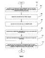
- FIG. 3illustrates a method 300 for allowing a user to remotely interface a computer telephony integration (CTI) architecture.
- CTIcomputer telephony integration
- a log-in requestmay be received from the remote user utilizing a network prior to providing an interface to the CTI architecture. See operation 302 .
- Such log-in requestis received from one of the work stations 114 .
- the networkpreferably takes the form of the Internet. Further, such log-in request may be sent using a Hypertext Transfer Protocol (HTTP) application using TCP/IP or IPX communication protocols. As an option, the HTTP application may include a network browser such as Microsoft® Internet Explorer®, Netscape® Navigator®, etc.
- HTTPHypertext Transfer Protocol
- the HTTP applicationmay include a network browser such as Microsoft® Internet Explorer®, Netscape® Navigator®, etc.
- the usermay access a predetermined web site using a designated Uniform Resource Locator (URL). Once accessed, the user may enter a user identifier and a password which is communicated to the push server 112 .
- a telephone numbermay also be entered that corresponds to a telephone that is currently in the proximity of the remote user. In such case, the telephone number may be encrypted for privacy purposes.
- a telephone numbermay be looked up at the CTI server 108 using the user identifier and password.
- a telephone callmay be received from a caller via the switch 102 , as indicated in operation 304 .
- the CTI server 108With the telephone number of the remote user in hand, the CTI server 108 subsequently routes the telephone call to the remote user in operation 306 .
- an identifier associated with the callermay be ascertained. Note operation 308 .
- Such identifiermay be of any type including, but not limited to a social security number, telephone number, credit card number, or any other identifier at least partly unique to the user.
- the identifiermay be automatically or manually ascertained.
- the identifiermay include information available from the telephone call, e.g. caller I.D.
- the switch 102may be capable of prompting the user to enter an identifier.
- the identifiermay be received from the user by way of a telephone touch pad, voice recognition, etc. These various types of entry may also be facilitated using the service desk software application running on the CTI server 108 .
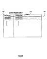
- FIG. 4illustrates an exemplary record table 400 .
- the record tablemay include a plurality of different identifiers 402 . Associated with each of the identifiers 402 are various descriptions, or information, 404 regarding the user which may be utilized during the telephone call by the operators 114 . It should be noted that the record table 400 may be used to store information on any group of people including customers, clients, personnel, etc. Further, the record table 400 may include any type of information relating to the users in as many or few fields as desired. The information may also facilitate the input of data that may be gathered during the course of the telephone call.
- the informationis sent to the remote user utilizing the Internet. Note operation 312 .
- the informationis capable of being viewed using the HTTP application.
- the informationmay be automatically displayed upon the receipt thereof by the HTTP application. This may be accomplished using push technology in the form of a pop-up window or the like.
- the informationmay be sent using URL'for the purpose of being read by the HTTP application.
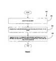
- FIG. 5illustrates one such method 500 for sending information to be read by the HTTP application. Initially, an event is identified in operation 502 .
- a URLis generated in operation 504 by the URL builder module 113 of the push server 112 .
- Such URLmay refer to a site on the network that is populated with the information retrieved in operation 310 shown in FIG. 3 .
- the URLis sent to a remote user by the push module 115 of the push server 112 utilizing a network such that the information relating to the event is automatically displayed via the HTTP application.
- the eventmay include an occurrence of any type
- the eventmay be a computer telephony integration (CTI) event in one preferred embodiment, as set forth hereinabove.
- CTIcomputer telephony integration
- the eventmay include a request to send a message between the remote user and another user, thus allowing messaging among users.
- a messagemay be entered via the HTTP application of a first user after which it is sent to the CTI system 100 .
- the first usermay be directly linked to the CTI system 100 for direct submission of the message by other means.
- the messageOnce the message resides in the CTI system 100 , it may be sent to the second user in a manner similar to the information relating to the call.
- the graphical user interface for facilitating such messagingwill be set forth in detail during reference to FIG. 6 .
- FIG. 6shows a graphical user interface 600 displayed with the HTTP application in order to allow a user to remotely interface the CTI architecture.
- a pop-up window 602may be used to display the information retrieved in operation 310 shown in FIG. 3 .
- a window 604may be used to display the information retrieved in operation 310 along with current status of the telephone connection between the remote user and the switch 102 that is established in operation 306 of FIG. 3 .
- the window 604may indicate whether the telephone 106 is currently in communication with the switch 102 , and the time when the communication was established.
- an initiate pop forwarding icon 605may be included for automatically forwarding information to another remote user. Any required data, i.e. receiver identifier, may be entered using fields that are displayed upon the selection of the pop forwarding icon 605 .
- disconnect icon 606for communicating a command to the CTI system 100 utilizing the network, i.e. the Internet, upon the selection thereof.
- Such disconnect icon 606disconnects the link between the switch 102 , and the telephone 106 and computer workstation 114 , thus terminating communication between the remote user and the CTI system 100 .
- a message window 608is included for displaying messages received in a manner set forth during reference to FIG. 5 .
- a message send icon 610may be used to enter messages to be sent to other users logged onto the CTI system 100 . Any required data, i.e. receiver identifier, may be entered using fields that are displayed upon the selection of the message send icon 610 .
- an extension window 612may be included for identifying the telephone to which the telephone call is routed in operation 306 of FIG. 3 . While not shown, this extension may be changed using a pull down menu, manual entry, or any other type of selection technique.
- the CTI system 100may be a component of a call center. Accordingly, the user may be a call center employee. As an option, the employee may interface the CTI architecture from a remote location such as a home, hotel room, etc. For additional mobility, the telephone call may even be routed via a cellular phone, using Internet telephony, or any communication medium for that matter.
Landscapes
- Engineering & Computer Science (AREA)
- Signal Processing (AREA)
- Telephonic Communication Services (AREA)
Abstract
Description
Claims (25)
Priority Applications (1)
| Application Number | Priority Date | Filing Date | Title |
|---|---|---|---|
| US09/608,801US6668054B1 (en) | 2000-06-30 | 2000-06-30 | Service desk system architecture for a mobile service workforce |
Applications Claiming Priority (1)
| Application Number | Priority Date | Filing Date | Title |
|---|---|---|---|
| US09/608,801US6668054B1 (en) | 2000-06-30 | 2000-06-30 | Service desk system architecture for a mobile service workforce |
Publications (1)
| Publication Number | Publication Date |
|---|---|
| US6668054B1true US6668054B1 (en) | 2003-12-23 |
Family
ID=29737045
Family Applications (1)
| Application Number | Title | Priority Date | Filing Date |
|---|---|---|---|
| US09/608,801Expired - LifetimeUS6668054B1 (en) | 2000-06-30 | 2000-06-30 | Service desk system architecture for a mobile service workforce |
Country Status (1)
| Country | Link |
|---|---|
| US (1) | US6668054B1 (en) |
Cited By (14)
| Publication number | Priority date | Publication date | Assignee | Title |
|---|---|---|---|---|
| US20030135562A1 (en)* | 2002-01-16 | 2003-07-17 | International Business Machines Corporation | Automatically sending a URL by e-mail or telephone |
| US20050163298A1 (en)* | 2004-01-22 | 2005-07-28 | International Business Machines Corporation | System and method for providing caller information across heterogeneous networks |
| US20080181386A1 (en)* | 2004-07-29 | 2008-07-31 | Thomas Creamer | Method, system and program product for dialed number service routing in a telephone network by reference to a database |
| US20090259562A1 (en)* | 2006-12-01 | 2009-10-15 | Sk Telecom Co., Ltd. | Method and apparatus for providing gift by using communication network and system including the apparatus |
| EP2297933B1 (en)* | 2008-06-20 | 2012-11-21 | NewVoiceMedia Limited | Method and system for handling a telephone call |
| US8984644B2 (en) | 2003-07-01 | 2015-03-17 | Securityprofiling, Llc | Anti-vulnerability system, method, and computer program product |
| US9100431B2 (en) | 2003-07-01 | 2015-08-04 | Securityprofiling, Llc | Computer program product and apparatus for multi-path remediation |
| US9118711B2 (en) | 2003-07-01 | 2015-08-25 | Securityprofiling, Llc | Anti-vulnerability system, method, and computer program product |
| US9118708B2 (en) | 2003-07-01 | 2015-08-25 | Securityprofiling, Llc | Multi-path remediation |
| US9118710B2 (en) | 2003-07-01 | 2015-08-25 | Securityprofiling, Llc | System, method, and computer program product for reporting an occurrence in different manners |
| US9118709B2 (en) | 2003-07-01 | 2015-08-25 | Securityprofiling, Llc | Anti-vulnerability system, method, and computer program product |
| US9117069B2 (en) | 2003-07-01 | 2015-08-25 | Securityprofiling, Llc | Real-time vulnerability monitoring |
| US9350752B2 (en) | 2003-07-01 | 2016-05-24 | Securityprofiling, Llc | Anti-vulnerability system, method, and computer program product |
| US9990667B2 (en) | 2006-12-01 | 2018-06-05 | Sk Planet Co., Ltd. | Method and apparatus for providing a gift using a mobile communication network and system including the apparatus |
Citations (5)
| Publication number | Priority date | Publication date | Assignee | Title |
|---|---|---|---|---|
| WO1999003247A2 (en) | 1997-07-09 | 1999-01-21 | Genesys Telecommunications Laboratories, Inc. | Methods in computer simulation of telephony systems |
| US5960073A (en)* | 1997-04-03 | 1999-09-28 | Genesys Telecommunications Laboratories , Inc. | Method and apparatus for providing an interactive home agent with access to call center functionality and resources |
| US6560222B1 (en)* | 1998-04-03 | 2003-05-06 | Vertical Networks, Inc. | Systems and methods for multiple voice and data communications using intelligently bridged TDM and packet buses and methods for performing telephony and data functions using the same |
| US6563788B1 (en)* | 1998-02-17 | 2003-05-13 | Genesys Telecommunications Laboratories, Inc. | Method and apparatus for call distribution and override with priority recognition and fairness timing routines |
| US6577726B1 (en)* | 2000-03-31 | 2003-06-10 | Siebel Systems, Inc. | Computer telephony integration hotelling method and system |
- 2000
- 2000-06-30USUS09/608,801patent/US6668054B1/ennot_activeExpired - Lifetime
Patent Citations (5)
| Publication number | Priority date | Publication date | Assignee | Title |
|---|---|---|---|---|
| US5960073A (en)* | 1997-04-03 | 1999-09-28 | Genesys Telecommunications Laboratories , Inc. | Method and apparatus for providing an interactive home agent with access to call center functionality and resources |
| WO1999003247A2 (en) | 1997-07-09 | 1999-01-21 | Genesys Telecommunications Laboratories, Inc. | Methods in computer simulation of telephony systems |
| US6563788B1 (en)* | 1998-02-17 | 2003-05-13 | Genesys Telecommunications Laboratories, Inc. | Method and apparatus for call distribution and override with priority recognition and fairness timing routines |
| US6560222B1 (en)* | 1998-04-03 | 2003-05-06 | Vertical Networks, Inc. | Systems and methods for multiple voice and data communications using intelligently bridged TDM and packet buses and methods for performing telephony and data functions using the same |
| US6577726B1 (en)* | 2000-03-31 | 2003-06-10 | Siebel Systems, Inc. | Computer telephony integration hotelling method and system |
Cited By (33)
| Publication number | Priority date | Publication date | Assignee | Title |
|---|---|---|---|---|
| US7593990B2 (en)* | 2002-01-16 | 2009-09-22 | International Business Machines Corporation | Automatically sending a URL by e-mail or telephone |
| US20030135562A1 (en)* | 2002-01-16 | 2003-07-17 | International Business Machines Corporation | Automatically sending a URL by e-mail or telephone |
| US10104110B2 (en) | 2003-07-01 | 2018-10-16 | Securityprofiling, Llc | Anti-vulnerability system, method, and computer program product |
| US9350752B2 (en) | 2003-07-01 | 2016-05-24 | Securityprofiling, Llc | Anti-vulnerability system, method, and computer program product |
| US10154055B2 (en) | 2003-07-01 | 2018-12-11 | Securityprofiling, Llc | Real-time vulnerability monitoring |
| US10050988B2 (en) | 2003-07-01 | 2018-08-14 | Securityprofiling, Llc | Computer program product and apparatus for multi-path remediation |
| US10021124B2 (en) | 2003-07-01 | 2018-07-10 | Securityprofiling, Llc | Computer program product and apparatus for multi-path remediation |
| US9225686B2 (en) | 2003-07-01 | 2015-12-29 | Securityprofiling, Llc | Anti-vulnerability system, method, and computer program product |
| US9117069B2 (en) | 2003-07-01 | 2015-08-25 | Securityprofiling, Llc | Real-time vulnerability monitoring |
| US9118709B2 (en) | 2003-07-01 | 2015-08-25 | Securityprofiling, Llc | Anti-vulnerability system, method, and computer program product |
| US8984644B2 (en) | 2003-07-01 | 2015-03-17 | Securityprofiling, Llc | Anti-vulnerability system, method, and computer program product |
| US9100431B2 (en) | 2003-07-01 | 2015-08-04 | Securityprofiling, Llc | Computer program product and apparatus for multi-path remediation |
| US9118711B2 (en) | 2003-07-01 | 2015-08-25 | Securityprofiling, Llc | Anti-vulnerability system, method, and computer program product |
| US9118708B2 (en) | 2003-07-01 | 2015-08-25 | Securityprofiling, Llc | Multi-path remediation |
| US9118710B2 (en) | 2003-07-01 | 2015-08-25 | Securityprofiling, Llc | System, method, and computer program product for reporting an occurrence in different manners |
| US20050163298A1 (en)* | 2004-01-22 | 2005-07-28 | International Business Machines Corporation | System and method for providing caller information across heterogeneous networks |
| US7142653B2 (en) | 2004-01-22 | 2006-11-28 | International Business Machines Corporation | System and method for providing caller information across heterogeneous networks |
| WO2005071980A1 (en)* | 2004-01-22 | 2005-08-04 | International Business Machines Corporation | System and method for providing caller information across heterogeneous networks |
| CN100591147C (en)* | 2004-01-22 | 2010-02-17 | 国际商业机器公司 | System and method for providing caller information across heterogeneous networks |
| US20080181386A1 (en)* | 2004-07-29 | 2008-07-31 | Thomas Creamer | Method, system and program product for dialed number service routing in a telephone network by reference to a database |
| US8175250B2 (en) | 2004-07-29 | 2012-05-08 | International Business Machines Corporation | Dialed number service routing in a telephone network by reference to a database |
| US9390408B2 (en)* | 2006-12-01 | 2016-07-12 | Sk Planet Co., Ltd. | Method and apparatus for providing gift by using communication network and system including the apparatus |
| US10007899B2 (en) | 2006-12-01 | 2018-06-26 | Sk Planet Co., Ltd. | Method and apparatus for providing a gift using a mobile communication network and system including the apparatus |
| US20090259562A1 (en)* | 2006-12-01 | 2009-10-15 | Sk Telecom Co., Ltd. | Method and apparatus for providing gift by using communication network and system including the apparatus |
| US10108944B2 (en) | 2006-12-01 | 2018-10-23 | Sk Planet Co., Ltd. | Method and apparatus for providing a gift using a mobile communication network and system including the apparatus |
| US10115091B2 (en) | 2006-12-01 | 2018-10-30 | Sk Planet Co., Ltd. | Method and apparatus for providing a gift using a mobile communication network and system including the apparatus |
| US10115090B2 (en) | 2006-12-01 | 2018-10-30 | Sk Planet Co., Ltd. | Method and apparatus for providing a gift using a mobile communication network and system including the apparatus |
| US10134021B2 (en) | 2006-12-01 | 2018-11-20 | Sk Planet Co., Ltd. | Method and apparatus for providing a gift using a mobile communication network and system including the apparatus |
| US9990667B2 (en) | 2006-12-01 | 2018-06-05 | Sk Planet Co., Ltd. | Method and apparatus for providing a gift using a mobile communication network and system including the apparatus |
| US10152701B2 (en) | 2006-12-01 | 2018-12-11 | Sk Planet Co., Ltd. | Method and apparatus for providing a gift using a mobile communication network and system including the apparatus |
| US10185941B2 (en) | 2006-12-01 | 2019-01-22 | Sk Planet Co., Ltd. | Method and apparatus for providing a gift using a mobile communication network and system including the apparatus |
| US10296877B2 (en) | 2006-12-01 | 2019-05-21 | Eleven Street Co., Ltd. | Method and apparatus for providing a gift using a mobile communication network and system including the apparatus |
| EP2297933B1 (en)* | 2008-06-20 | 2012-11-21 | NewVoiceMedia Limited | Method and system for handling a telephone call |
Similar Documents
| Publication | Publication Date | Title |
|---|---|---|
| US6690672B1 (en) | Method and apparatus for placing an intelligent telephone call using an internet browser | |
| JP3226929B2 (en) | Apparatus and method for coordinating telephone and data communications | |
| US6567848B1 (en) | System for coordinating communication between a terminal requesting connection with another terminal while both terminals accessing one of a plurality of servers under the management of a dispatcher | |
| US8982877B2 (en) | Provision of telephony caller ID service via common instant communications clients | |
| US6654815B1 (en) | Contact server for call center | |
| US6519628B1 (en) | Method and system for customer service using a packet switched network | |
| US5793861A (en) | Transaction processing system and method | |
| US8917857B2 (en) | Method and system for call to role | |
| US6668054B1 (en) | Service desk system architecture for a mobile service workforce | |
| US20020194272A1 (en) | Method for establishing a communication connection between two or more users via a network of interconnected computers | |
| US20030086556A1 (en) | System and method for providing computer telephony integration over a computer network | |
| CA2161506C (en) | File retrieval with incoming calls | |
| WO2004021128A2 (en) | Enhanced contact navigator with interactive tabs for managing network events in real time | |
| US20030187971A1 (en) | Enterprise macro-manager of contact center communications technologies | |
| JP3594219B2 (en) | Communication method, communication system, recording medium storing software product for controlling communication | |
| EP1832102B1 (en) | Registration of a telephone/computer association in a computer telephony integration environment | |
| CA2666164A1 (en) | Methods and systems for providing a name-based communication service | |
| GB2346718A (en) | Client server system supporting collaboration |
Legal Events
| Date | Code | Title | Description |
|---|---|---|---|
| AS | Assignment | Owner name:NETWORK ASSOCIATES, INC., CALIFORNIA Free format text:ASSIGNMENT OF ASSIGNORS INTEREST;ASSIGNORS:CONTINO, SALVATORE J.;LING, MEI;REEL/FRAME:010911/0710 Effective date:20000622 | |
| AS | Assignment | Owner name:NETWORK ASSOCIATES, INC., CALIFORNIA Free format text:ASSIGNMENT OF ASSIGNORS INTEREST;ASSIGNORS:CONTINO, SALVATORE J.;LING, MEI;REEL/FRAME:011079/0535 Effective date:20000725 | |
| AS | Assignment | Owner name:NETWORKS ASSOCIATES TECHNOLOGY, INC., CALIFORNIA Free format text:ASSIGNMENT OF ASSIGNORS INTEREST;ASSIGNOR:NETWORKS ASSOCIATES, INC., D/B/A NETWORK ASSOCIATES, INC.;REEL/FRAME:012627/0427 Effective date:20020118 | |
| STCF | Information on status: patent grant | Free format text:PATENTED CASE | |
| FPAY | Fee payment | Year of fee payment:4 | |
| AS | Assignment | Owner name:BMC SOFTWARE, INC., TEXAS Free format text:ASSIGNMENT OF ASSIGNORS INTEREST;ASSIGNOR:NETWORK ASSOCIATES, INC.;REEL/FRAME:021380/0310 Effective date:20040130 | |
| FPAY | Fee payment | Year of fee payment:8 | |
| AS | Assignment | Owner name:CREDIT SUISSE AG, CAYMAN ISLANDS BRANCH, AS COLLATERAL AGENT, NORTH CAROLINA Free format text:SECURITY AGREEMENT;ASSIGNORS:BMC SOFTWARE, INC.;BLADELOGIC, INC.;REEL/FRAME:031204/0225 Effective date:20130910 Owner name:CREDIT SUISSE AG, CAYMAN ISLANDS BRANCH, AS COLLAT Free format text:SECURITY AGREEMENT;ASSIGNORS:BMC SOFTWARE, INC.;BLADELOGIC, INC.;REEL/FRAME:031204/0225 Effective date:20130910 | |
| FPAY | Fee payment | Year of fee payment:12 | |
| AS | Assignment | Owner name:CREDIT SUISSE, AG, CAYMAN ISLANDS BRANCH, AS COLLATERAL AGENT, NEW YORK Free format text:SECURITY INTEREST;ASSIGNORS:BMC SOFTWARE, INC.;BLADELOGIC, INC.;REEL/FRAME:047185/0744 Effective date:20181002 Owner name:CREDIT SUISSE, AG, CAYMAN ISLANDS BRANCH, AS COLLA Free format text:SECURITY INTEREST;ASSIGNORS:BMC SOFTWARE, INC.;BLADELOGIC, INC.;REEL/FRAME:047185/0744 Effective date:20181002 | |
| AS | Assignment | Owner name:BMC ACQUISITION L.L.C., TEXAS Free format text:RELEASE OF PATENTS;ASSIGNOR:CREDIT SUISSE AG, CAYMAN ISLANDS BRANCH;REEL/FRAME:047198/0468 Effective date:20181002 Owner name:BMC SOFTWARE, INC., TEXAS Free format text:RELEASE OF PATENTS;ASSIGNOR:CREDIT SUISSE AG, CAYMAN ISLANDS BRANCH;REEL/FRAME:047198/0468 Effective date:20181002 Owner name:BLADELOGIC, INC., TEXAS Free format text:RELEASE OF PATENTS;ASSIGNOR:CREDIT SUISSE AG, CAYMAN ISLANDS BRANCH;REEL/FRAME:047198/0468 Effective date:20181002 | |
| AS | Assignment | Owner name:THE BANK OF NEW YORK MELLON TRUST COMPANY, N.A., AS COLLATERAL AGENT, TEXAS Free format text:SECURITY INTEREST;ASSIGNORS:BMC SOFTWARE, INC.;BLADELOGIC, INC.;REEL/FRAME:052844/0646 Effective date:20200601 Owner name:THE BANK OF NEW YORK MELLON TRUST COMPANY, N.A., AS COLLATERAL AGENT, TEXAS Free format text:SECURITY INTEREST;ASSIGNORS:BMC SOFTWARE, INC.;BLADELOGIC, INC.;REEL/FRAME:052854/0139 Effective date:20200601 | |
| AS | Assignment | Owner name:ALTER DOMUS (US) LLC, ILLINOIS Free format text:GRANT OF SECOND LIEN SECURITY INTEREST IN PATENT RIGHTS;ASSIGNORS:BMC SOFTWARE, INC.;BLADELOGIC, INC.;REEL/FRAME:057683/0582 Effective date:20210930 | |
| AS | Assignment | Owner name:BLADELOGIC, INC., TEXAS Free format text:TERMINATION AND RELEASE OF SECURITY INTEREST IN PATENTS;ASSIGNOR:ALTER DOMUS (US) LLC;REEL/FRAME:066567/0283 Effective date:20240131 Owner name:BMC SOFTWARE, INC., TEXAS Free format text:TERMINATION AND RELEASE OF SECURITY INTEREST IN PATENTS;ASSIGNOR:ALTER DOMUS (US) LLC;REEL/FRAME:066567/0283 Effective date:20240131 | |
| AS | Assignment | Owner name:GOLDMAN SACHS BANK USA, AS SUCCESSOR COLLATERAL AGENT, NEW YORK Free format text:OMNIBUS ASSIGNMENT OF SECURITY INTERESTS IN PATENT COLLATERAL;ASSIGNOR:CREDIT SUISSE AG, CAYMAN ISLANDS BRANCH, AS RESIGNING COLLATERAL AGENT;REEL/FRAME:066729/0889 Effective date:20240229 | |
| AS | Assignment | Owner name:BLADELOGIC, INC., TEXAS Free format text:RELEASE OF SECURITY INTEREST IN PATENTS PREVIOUSLY RECORDED AT REEL/FRAME (052854/0139);ASSIGNOR:THE BANK OF NEW YORK MELLON TRUST COMPANY, N.A., AS COLLATERAL AGENT;REEL/FRAME:068339/0617 Effective date:20240731 Owner name:BMC SOFTWARE, INC., TEXAS Free format text:RELEASE OF SECURITY INTEREST IN PATENTS PREVIOUSLY RECORDED AT REEL/FRAME (052854/0139);ASSIGNOR:THE BANK OF NEW YORK MELLON TRUST COMPANY, N.A., AS COLLATERAL AGENT;REEL/FRAME:068339/0617 Effective date:20240731 Owner name:BLADELOGIC, INC., TEXAS Free format text:RELEASE OF SECURITY INTEREST IN PATENTS PREVIOUSLY RECORDED AT REEL/FRAME (052844/0646);ASSIGNOR:THE BANK OF NEW YORK MELLON TRUST COMPANY, N.A., AS COLLATERAL AGENT;REEL/FRAME:068339/0408 Effective date:20240731 Owner name:BMC SOFTWARE, INC., TEXAS Free format text:RELEASE OF SECURITY INTEREST IN PATENTS PREVIOUSLY RECORDED AT REEL/FRAME (052844/0646);ASSIGNOR:THE BANK OF NEW YORK MELLON TRUST COMPANY, N.A., AS COLLATERAL AGENT;REEL/FRAME:068339/0408 Effective date:20240731 | |
| AS | Assignment | Owner name:BMC HELIX, INC., TEXAS Free format text:ASSIGNMENT OF ASSIGNORS INTEREST;ASSIGNOR:BMC SOFTWARE, INC.;REEL/FRAME:070442/0197 Effective date:20250101 |