US6667714B1 - Downtilt control for multiple antenna arrays - Google Patents
Downtilt control for multiple antenna arraysDownload PDFInfo
- Publication number
- US6667714B1 US6667714B1US09/564,094US56409400AUS6667714B1US 6667714 B1US6667714 B1US 6667714B1US 56409400 AUS56409400 AUS 56409400AUS 6667714 B1US6667714 B1US 6667714B1
- Authority
- US
- United States
- Prior art keywords
- phase
- motion
- common motor
- linkage
- antenna
- Prior art date
- Legal status (The legal status is an assumption and is not a legal conclusion. Google has not performed a legal analysis and makes no representation as to the accuracy of the status listed.)
- Expired - Lifetime
Links
Images


Classifications
- H—ELECTRICITY
- H01—ELECTRIC ELEMENTS
- H01Q—ANTENNAS, i.e. RADIO AERIALS
- H01Q21/00—Antenna arrays or systems
- H01Q21/28—Combinations of substantially independent non-interacting antenna units or systems
- H—ELECTRICITY
- H01—ELECTRIC ELEMENTS
- H01Q—ANTENNAS, i.e. RADIO AERIALS
- H01Q1/00—Details of, or arrangements associated with, antennas
- H01Q1/12—Supports; Mounting means
- H01Q1/22—Supports; Mounting means by structural association with other equipment or articles
- H01Q1/24—Supports; Mounting means by structural association with other equipment or articles with receiving set
- H01Q1/241—Supports; Mounting means by structural association with other equipment or articles with receiving set used in mobile communications, e.g. GSM
- H01Q1/246—Supports; Mounting means by structural association with other equipment or articles with receiving set used in mobile communications, e.g. GSM specially adapted for base stations
- H—ELECTRICITY
- H01—ELECTRIC ELEMENTS
- H01Q—ANTENNAS, i.e. RADIO AERIALS
- H01Q3/00—Arrangements for changing or varying the orientation or the shape of the directional pattern of the waves radiated from an antenna or antenna system
- H01Q3/26—Arrangements for changing or varying the orientation or the shape of the directional pattern of the waves radiated from an antenna or antenna system varying the relative phase or relative amplitude of energisation between two or more active radiating elements; varying the distribution of energy across a radiating aperture
- H01Q3/30—Arrangements for changing or varying the orientation or the shape of the directional pattern of the waves radiated from an antenna or antenna system varying the relative phase or relative amplitude of energisation between two or more active radiating elements; varying the distribution of energy across a radiating aperture varying the relative phase between the radiating elements of an array
- H01Q3/32—Arrangements for changing or varying the orientation or the shape of the directional pattern of the waves radiated from an antenna or antenna system varying the relative phase or relative amplitude of energisation between two or more active radiating elements; varying the distribution of energy across a radiating aperture varying the relative phase between the radiating elements of an array by mechanical means
Definitions
- the present inventionis related to techniques for controlling the downtilt angle of phased-array antennas, such as those used in the base stations of wireless communication networks.
- base stationsIn a conventional wireless communication network, communications with wireless units (e.g., mobile telephones) are supported by base stations, each configured with one or more antennas that provide communication coverage over an area surrounding the base station referred to as the base station cell.
- a typical base station cellmay be divided into (e.g., three) sectors, with different antennas configured to support communications for the different sectors.
- base station antennasIn order to provide a relatively large cell size, base station antennas are typically configured at a higher height (e.g., on the tops of transmission towers) than the wireless units located within that cell.
- base station antennasIn order to communicate with wireless units located anywhere within a base station cell, including right next to the base station itself, base station antennas are typically configured with a downtilt angle to “point” the antennas down to provide the appropriate coverage.
- One way to configure an antenna with a downtilt angleis to physically mount the antenna pointing at an angle below horizontal.
- Another way to achieve a downtilt angleis to use a phased-array antenna that can be pointed “electrically” by selecting appropriate phase shifts at the various antenna elements in the array.
- FIG. 1shows a block diagram of a conventional N-element, parallel-fed, fixed-phase, phased-array antenna 100 .
- Antenna 100comprises a power splitter 102 , N phase shifters 104 , each phase shifter configured with a corresponding antenna element 106 , where the N phase shifters 104 are configured in parallel to power splitter 102 .
- Power splitter 102receives an RF signal and distributes that RF signal to the N phase shifters 104 (e.g., splitting the signal power equally or in a shaped (e.g., cosine) manner among the different phase shifters).
- Each phase shifter 104 ishifts the phase of its received portion of the RF signal by a particular fixed phase-shift angle ⁇ i and passes the resulting phase-shifted RF signal to its corresponding antenna element 106 i , which radiates that phase-shifted portion of the RF signal as a wireless electromagnetic (E-M) signal.
- E-Mwireless electromagnetic
- the resulting composite radiated E-M signal from the entire antenna arraywill form a uniform wavefront that propagates in a particular direction.
- the element array of antenna 100is configured with a progressive phase shift such that the phase-shift angle ⁇ i applied by each phase shifter 104 i increases linearly from the first phase shifter 104 1 through the N th phase shifter 104 N .
- antenna 100can also be configured to receive RF signals, either at the same time as, or instead of, being configured to transmit RF signals, in which case, power splitter 102 (also) functions as a power combiner.
- the phase-shift angle ⁇ i for the last few phase shifters 104 ican become very large. This is not a problem for fixed-angle arrays.
- the heights of base station antennasmay vary from cell to cell, and the sizes of cells may vary from base station to base station, the magnitude of the downtilt angle will also typically vary from cell to cell.
- the desired antenna footprint for a particular base station antennamay also vary over time, for example, as more base stations are configured within an existing covered geographic area. As such, it is not always practical to design base station antenna arrays with a fixed downtilt angle.
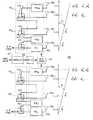
- FIG. 2shows a block diagram of a conventional N-element, parallel-fed, variable-phase, phased-array antenna 200 .
- antenna 200comprises a power splitter 202 , N phase shifters 204 , each with a corresponding antenna element 206 , where the N phase shifters 204 are configured in parallel to power splitter 202 .
- the N phase shifters 204are configured as part of a phase-shifter assembly 208 , which is configured to a motor 210 , which is in turn configured to a controller 212 .
- Controller 212receives phase control signals that determine how to control the operations of motor 210 , which in turn drives phase-shifter assembly 208 .
- Phase-shifter assembly 208is typically a mechanical device with movable components (as driven by motor 210 ) whose movements affect the electro-magnetic characteristics (e.g., line length) of the various phase shifters 204 to change the magnitude of the phase-shift angle ⁇ i applied by each phase shifter 204 i in a controlled manner.
- a single antenna designcan be used for different base stations having different antenna heights that require different and varying downtilt angles.
- phased-array antennascan have relatively wide bandwidths.
- Typical wireless communication networksuse different frequency bands for uplink (i.e., wireless unit to base station) and downlink (i.e., base station to wireless unit) communications.
- uplinki.e., wireless unit to base station
- downlinki.e., base station to wireless unit
- a single antenna arraymay be able to support both the uplink and downlink frequency bands. In that case, a single phased-array antenna can be used to both transmit downlink signals to the wireless units and receive uplink signals from the wireless units.
- phase shifterse.g., 204 N , 204 N ⁇ 1 , . . .
- phase-shift angles ⁇e.g., from as small as 0 degrees for a zero downtilt angle to as large as 180 degrees for a downtilt angle of 4 degrees.
- series-fed phased-array antennasare typically used.
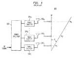
- FIG. 3shows a block diagram of a conventional N-element, series-fed, variable-phase, phased-array antenna 300 .
- antenna 300comprises a power splitter 302 , a phase-shifter assembly 308 with N phase shifters 304 , each with a corresponding antenna element 306 , a motor 310 that drives phase-shifter assembly 308 and a controller 312 that controls motor 310 .
- the N phase shifters 304 in phase-shifter assembly 308are configured in series with (N ⁇ 1) power couplers 314 within a power-splitter assembly 302 . As indicated in FIG.
- the outgoing RF signal received by power-splitter assembly 302is split by the first coupler 314 1 into two RF signals: one of which is phase-shifted by the first phase shifter 304 1 by a phase-shift angle ⁇ 1 for radiation by the first antenna element 306 1 and the other of which is transmitted to the second phase shifter 304 2 , which applies a phase-shift angle ⁇ 2 .
- phase shifter 304 1can be omitted.
- phase-shifted RF signal from phase shifter 304 2is then further split by the second coupler 314 2 into two RF signals: one of which is transmitted by the second antenna element 306 2 and the other of which is transmitted to the third phase shifter 304 3 , which applies a further phase-shift angle ⁇ 3 to the already phase-shifted RF signal.
- the phase-shifted RF signal from phase shifter 304 3is then further split by the third coupler 314 3 into two RF signals: one of which is transmitted by the third antenna element 306 3 and the other of which is transmitted to the fourth phase shifter (not shown), which applies a fourth phase-shift angle ⁇ 4 to the twice phase-shifted RF signal.
- the RF signal radiated by the third antenna element 306 3has a total phase shift equal to the sum of the phase-shift angles applied by the second and third phase shifters 304 2 and 304 3 or ( ⁇ 2 + ⁇ 3 ).
- Coupler 314 N ⁇ 1splits its received RF signal into two RF signals: one of which is transmitted by antenna element 306 N ⁇ 1 with a total phase shift of ( ⁇ 2 + ⁇ 3 +. . . + ⁇ N ⁇ 1 ) and the other of which is transmitted to the last phase shifter 304 N , which applies a final phase-shift angle ⁇ N to the already multiply phase-shifted RF signal before passing the resulting RF signal to the last antenna element 306 N , whose radiated signal has a total phase shift of ( ⁇ 2 + ⁇ 3 +. . . + ⁇ N ⁇ 1 + ⁇ N ).
- phase shifters 304 and power couplers 314are configured in series (rather than in parallel as in antennas 100 and 200 ) and since phase shifts are additive, each preceding phase shifter in the series only needs to apply a fraction of the overall phase shift for each antenna element 306 to achieve the desired progressive phase shift for the overall antenna array.
- a series-fed, variable-phase, phased-array antennasuch as antenna 300 can be designed to provide a wide range of downtilt angles, since each phase shifter needs only to provide a fraction of the overall phase range and is therefore more easily realized.
- two separate antenna arraysmay be needed to support communications between a base station and the corresponding wireless units, with one antenna array designed for the uplink frequency band and the other antenna array designed for the downlink frequency band.
- the footprints of these uplink and downlink antenna arraysneed to be the same and, as a result, their respective downtilt angles need to be able to be coordinated to achieve such common coverage areas.
- the present inventionis directed to an apparatus for simultaneously controlling the downtilt angles of two (or more) different variable-phase phased-array antennas, such as those used for uplink and downlink communications at a base station of a wireless communication network. Because the uplink and downlink frequency bands in typical wireless communication networks are different, for a common downtilt angle, the progressive phase shifts will be different for the uplink and downlink antennas. The present invention preferably takes those differences into account to achieve coordinated control over downtilt angle for the two different antenna arrays.
- the present inventionis an apparatus for simultaneously controlling downtilt angles of two or more arrays of antenna elements, comprising (a) for each array, a power splitter and a phase-shifter assembly configured to control the progressive phase shifts between successive elements in the array; (b) a common linkage connected to one or more movable components of each phase-shifter assembly; (c) a common motor configured to the linkage to convert motion of the common motor into motion of the linkage; and (d) a controller configured to control the motion of the common motor, wherein the motion of the common motor causes the motion of the linkage which simultaneously moves the one or more components within each phase-shifter assembly to change the progressive phase shifts between successive elements in the corresponding array, thereby simultaneously changing the downtilt angles of the two or more arrays in a coordinated fashion.
- the present inventionis an antenna system for a base station of a wireless communication network, comprising (a) an uplink array of antenna elements; (b) a downlink array of antenna elements; (c) an uplink power-combiner and an uplink phase-shifter assembly configured to control progressive phase shifts between successive array elements in the uplink array; (d) a downlink power-splitter and a downlink phase-shifter assembly configured to control progressive phase shifts between successive array elements in the downlink array; (e) a common linkage connected to one or more movable components of both the uplink and downlink phase-shifter assemblies; (f) a common motor configured to the linkage to convert motion of the common motor into motion of the linkage; and (g) a controller configured to control the motion of the common motor, wherein the motion of the common motor causes the motion of the linkage which simultaneously moves the one or more components within the uplink and downlink power-splitter/phase-shifter assemblies to simultaneously change the progressive phase shifts between successive elements in the uplink
- FIG. 1shows a block diagram of a conventional N-element, parallel-fed, fixed-phase, phased-array antenna
- FIG. 2shows a block diagram of a conventional N-element, parallel-fed, variable-phase, phased-array antenna
- FIG. 3shows a block diagram of a conventional N-element, series-fed, variable-phase, phased-array antenna
- FIG. 4shows a block diagram of an antenna system for a base station of a wireless communication network, according to one embodiment of the present invention
- FIG. 5shows a schematic diagram of a base station tower configured with the uplink and downlink antennas of the antenna system of FIG. 4;
- FIG. 6shows a schematic diagram of an integrated uplink power-splitter/phase-shifter assembly for the uplink antenna of FIG. 4 and an integrated downlink power-splitter/phase-shifter assembly for the downlink antenna of FIG. 4 configured with a common linkage, according to one embodiment of the present invention in which each phased-array antenna has four antenna elements.
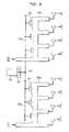
- FIG. 4shows a block diagram of an antenna system 400 for a base station of a wireless communication network, according to one embodiment of the present invention.
- Antenna system 400comprises two different N-element, series-fed, variable-phase, phased-array antennas: uplink antenna 401 U configured to receive RF signals in the uplink frequency band from one or more wireless units, and downlink antenna 401 D configured to transmit RF signals in the downlink frequency band to the same one or more wireless units.
- FIG. 5shows a schematic diagram of a base station tower 502 configured with uplink antenna 401 U and downlink antenna 401 D of antenna system 400 of FIG. 4 .
- each phased-array antenna in antenna system 400has a power-splitter assembly 402 with N ⁇ 1 couplers 414 , a phase-shifter assembly 408 with N phase shifters 404 , each phase shifter configured with a corresponding antenna element 406 , where the N ⁇ 1 couplers 414 are configured in series with the N phase shifters 404 , analogous to that described for antenna 300 of FIG. 3 .
- power-splitter assembly 402 Ufunctions as a “power-combiner” assembly.
- antenna system 400has a controller 412 , which controls the rotational motion of a motor 410 , which drives a mechanical linkage 409 , which in turn is connected to drive the positions of movable components within both phase-shifter assemblies 408 U and 408 D to simultaneously change the downtilt angles for both the uplink and downlink antennas 401 U and 401 D , respectively.
- a single electro-mechanical actuator(comprising controller 412 , motor 410 , and linkage 409 ) is used to control and coordinate changes in the downtilt angles for both the uplink and downlink antennas.
- the progressive phase shift needed to achieve a particular downtilt angle ⁇ U for uplink antenna 401 Uwill typically be different from the progressive phase shift needed to achieve the equivalent downtilt angle ⁇ D for downlink antenna 401 D .
- phase-shift angle ⁇ 2 U applied by the second phase-shifter 404 U2 in phase-shifter assembly 408 U of uplink antenna 401 Uwill typically be different from the phase-shift angle ⁇ 2 D applied by corresponding phase shifter 404 D2 in phase-shifter assembly 408 D of downlink antenna 401 D .
- phase shifters 404 U1 and 404 D1can both be omitted.
- the different progressive phase-shift valuesare taken into account when designing phase-shifter assemblies 408 U and 408 D , such that motion of motor 410 is translated into equivalent changes in the two downtilt angles ⁇ U and ⁇ D .
- the two phase-shift assemblieswill typically have different geometries and/or different electrical characteristics to achieve the two different progressive phase shifts.
- the uplink and downlink antennashave substantially the same downtilt angle so that they achieve the same footprints. This might enable the downtilt angle to be set efficiently based on only one set of measurements. For example, field testing could be limited to measurement of received signal strength throughout the cell for downlink transmission from the base station to a test mobile. Since the uplink and downlink downtilt angles will be known to be equivalent, actual test confirmation of adequate downlink coverage will imply that adequate uplink coverage is also achieved.
- the uplink and downlink antennasare mounted at substantially different heights on a base station tower or where different coverage patterns are desired, different downtilt angles may be needed for the uplink and downlink antennas to achieve the same antenna footprints. In such cases, the different required downtilt angles are taken into consideration when designing phase-shifter assemblies 408 U and 408 D.
- linkage 409is a rigid structure that is connected to motor 410 through one or more gear boxes that translate rotational motion of motor 410 into uniform translational motion of the movable components within both the uplink and downlink phase-shifter assemblies.
- the different progressive phase-shift valuescan also be taken into account when designing mechanical linkage 409 , such that rotational motion of motor 410 is translated into non-uniform translational motion by linkage 409 for uplink antenna 401 U and for downlink antenna 401 D.
- FIG. 6shows a schematic diagram of an integrated uplink power-splitter/phase-shifter assembly 602 U for uplink antenna 401 U and an integrated downlink power-splitter/phase-shifter assembly 602 D for downlink antenna 401 D of FIG. 4 configured to a common linkage 409 , according to one embodiment of the present invention in which each phased-array antenna has four antenna elements 406 .
- Each integrated assembly 602integrates the power-splitting functionality of one of the power-splitter assemblies 402 of FIG. 4 with the phase-shifting functionality of the corresponding phase-shifter assembly 408 .
- Each integrated assembly 602comprises a series of dielectric wedges 604 sandwiched between a microstrip conductor 606 and a lower, conducting, ground plane (not shown), where each dielectric wedge 604 is connected to linkage 409 , which controls the “depth” of insertion of each dielectric wedge 604 between the corresponding microstrip conductor 606 and the ground plane.
- Each integrated power-splitter/phase-shifter assembly shown in FIG. 6is an air dielectric suspended microstrip line realized in sheet metal and based on a dielectric wedge, series-fed, phase-shifter assembly that is described in further detail in U.S. Pat. No. 5,940,030.
- Another suitable type of integrated power-splitter/phase-shifter assembly for the present inventionis the sliding-short, reflection-mode, series-fed, phase-shifter assembly, which is another type of air dielectric suspended microstrip line realized in sheet metal and is described in U.S. patent application Nos. 09/148,442, filed on Sep. 4, 1998, and 09/148,449, filed on Sep. 4, 1998.
- phase-shifter assembliescombine the N ⁇ 1 couplers (i.e., 414 in FIG. 4) of a power-splitter assembly and the N phase-shifters (i.e., 404 in FIG. 4) of a phase-shifter assembly into a single integrated device that provides the functions of both power splitting (or combining) and series-fed phase shifting.
- Uplink microstrip conductor 606 Uis configured to receive the different RF signals received at the different antenna elements 406 U of uplink antenna 401 U from the wireless units and provide a phase-shifted, combined receive (RX) RF signal.
- downlink microstrip conductor 606 Dis configured to accept a transmit (TX) RF signal and provide differently phase-shifted RF signals to the various transmit antenna elements 406 D of downlink antenna 401 D for propagation to the wireless units. Impedance transformations due to line-width changes control the magnitude ratios for the power-splitting (or combining) function for the individual antenna array elements. Between successive antenna elements, a solid dielectric wedge 604 is introduced in place of the air, underneath the suspended conducting line.
- each dielectric wedge 604 between the corresponding microstrip conductor 606 and the ground planedetermines the amount of dielectric material located between the microstrip conductor and the ground plane, which in turn determines the amount of phase shift applied to the RF signal at that location along the microstrip conductor.
- rotational (or linear) motion of motor 410(which is preferably a linear stepper motor) is translated into translational motion of linkage 409 by a suitable gear box 608 .
- Translational motion of linkage 409i.e., left-to-right motion in FIG. 6) moves more of each dielectric wedge 604 (right in FIG. 6) between microstrip conductor 606 and the ground plane (and vice versa), thereby affecting the electromagnetic characteristics for signals propagating along microstrip conductor 606 .
- moving dielectric wedges 604changes the amount of phase shift applied to the RF signal as it propagates along microstrip conductor 606 .
- the amount of phase shift applied by the various wedges and therefore the overall progressive phase shift of the integrated power-splitter/phase-shifter assemblycan be accurately controlled for the entire range of motion of linkage 409 .
- the shapes of the upper and lower microstrip conductors 606 U and 606 Dare different to take into account differences between the uplink and downlink frequency ranges.
- the thicknesses, sizes, shapes, and positions of the dielectric wedges 604may also vary from wedge to wedge and from antenna to antenna, either in addition to or instead of the differing shapes of the microstrip conductors 606 .
- FIG. 5shows the uplink antenna 401 U configured above the downlink antenna 401 D
- the present inventioncan be implemented with alternative configurations, including those with the downlink antenna above the uplink antenna and those with the uplink and downlink antennas configured side-by-side.
- FIG. 4shows uplink and downlink antennas 401 U and 401 D both with N antenna elements, it will be understood that the present invention can be implemented with uplink and downlink arrays having differing numbers of antenna elements.
- the present inventionhas been described in the context of series-fed, variable-phase, phased-array antennas, it will be understood that the present invention could also be implemented for parallel-fed, variable-phase, phased-array antennas.
- the present inventionhas been described in the context of simultaneously controlling two variable-phase, phased-array antennas, one for transmitting downlink signals and one for receiving uplink signals, it will be understood that, in general, the present invention can be implemented to simultaneously control two or more variable-phase, phased-array antennas, where each different antenna may be differently used for transmitting only, receiving only, or both transmitting and receiving.
Landscapes
- Engineering & Computer Science (AREA)
- Computer Networks & Wireless Communication (AREA)
- Variable-Direction Aerials And Aerial Arrays (AREA)
Abstract
Description
Claims (13)
Priority Applications (1)
| Application Number | Priority Date | Filing Date | Title |
|---|---|---|---|
| US09/564,094US6667714B1 (en) | 2000-05-03 | 2000-05-03 | Downtilt control for multiple antenna arrays |
Applications Claiming Priority (1)
| Application Number | Priority Date | Filing Date | Title |
|---|---|---|---|
| US09/564,094US6667714B1 (en) | 2000-05-03 | 2000-05-03 | Downtilt control for multiple antenna arrays |
Publications (1)
| Publication Number | Publication Date |
|---|---|
| US6667714B1true US6667714B1 (en) | 2003-12-23 |
Family
ID=29736975
Family Applications (1)
| Application Number | Title | Priority Date | Filing Date |
|---|---|---|---|
| US09/564,094Expired - LifetimeUS6667714B1 (en) | 2000-05-03 | 2000-05-03 | Downtilt control for multiple antenna arrays |
Country Status (1)
| Country | Link |
|---|---|
| US (1) | US6667714B1 (en) |
Cited By (49)
| Publication number | Priority date | Publication date | Assignee | Title |
|---|---|---|---|---|
| US20040209572A1 (en)* | 2001-10-22 | 2004-10-21 | Thomas Louis David | Antenna system |
| US20040246175A1 (en)* | 2001-10-22 | 2004-12-09 | Thomas Louis David | Apparatus for steering an antenna system |
| US20040252055A1 (en)* | 2001-11-14 | 2004-12-16 | Thomas Louis David | Antenna system |
| US20040263410A1 (en)* | 2001-03-20 | 2004-12-30 | Allen Telecom Group, Inc. | Antenna array |
| US20050001778A1 (en)* | 2003-07-03 | 2005-01-06 | Kevin Le | Wideband dual polarized base station antenna offering optimized horizontal beam radiation patterns and variable vertical beam tilt |
| US6914572B1 (en)* | 2001-02-27 | 2005-07-05 | Sprint Communications Company L.P. | Antenna control system in a wireless communication system |
| US20050179610A1 (en)* | 2002-12-13 | 2005-08-18 | Kevin Le | Directed dipole antenna |
| US20060077098A1 (en)* | 2004-10-13 | 2006-04-13 | Andrew Corporation | Panel antenna with variable phase shifter |
| WO2006057613A1 (en) | 2004-11-26 | 2006-06-01 | Powerwave Technologies Sweden Ab | Antenna control system |
| WO2008079065A1 (en)* | 2006-12-22 | 2008-07-03 | Telefonaktiebolaget Lm Ericsson (Publ) | Antenna arrangement |
| US7557675B2 (en) | 2005-03-22 | 2009-07-07 | Radiacion Y Microondas, S.A. | Broad band mechanical phase shifter |
| US20090203406A1 (en)* | 2000-07-10 | 2009-08-13 | Andrew Corporation | Cellular antenna |
| US20100201591A1 (en)* | 2009-02-11 | 2010-08-12 | Gregory Girard | Multi-beam antenna with multi-device control unit |
| US20110183624A1 (en)* | 2010-01-28 | 2011-07-28 | Thiagarajar College Of Engineering | Devices and Methods for Phase Shifting a Radio Frequency (RF) Signal for a Base Station Antenna |
| US20110261773A1 (en)* | 2008-11-14 | 2011-10-27 | Sharp Kabushiki Kaisha | Antenna apparatus and base station apparatus |
| US20150002361A1 (en)* | 2012-03-20 | 2015-01-01 | Huawei Technologies Co., Ltd. | Antenna device and system |
| US20150023202A1 (en)* | 2002-05-14 | 2015-01-22 | Genghiscomm Holdings, LLC | Cooperative Wireless Networks |
| US20150061936A1 (en)* | 2013-08-28 | 2015-03-05 | Harris Corporation | Dual polarization ground-based phased array antenna system for aircraft communications and associated methods |
| CN105761249A (en)* | 2016-02-01 | 2016-07-13 | 南京工程学院 | Method for calculation of antenna mechanical tilt based on image |
| US9800448B1 (en) | 2002-05-14 | 2017-10-24 | Genghiscomm Holdings, LLC | Spreading and precoding in OFDM |
| US9967007B2 (en) | 2002-05-14 | 2018-05-08 | Genghiscomm Holdings, LLC | Cooperative wireless networks |
| US10056948B1 (en)* | 2017-05-31 | 2018-08-21 | Corning Research & Development Corporation | Distributing multiple-input, multiple-output (MIMO) communications streams to remove units in a distributed communication system (DCS) to support configuration of interleaved MIMO communications services |
| US20180287255A1 (en)* | 2017-03-30 | 2018-10-04 | Commscope Technologies Llc | Base station antennas that are configurable for either independent or common down tilt control and related methods |
| US10211529B2 (en)* | 2006-11-10 | 2019-02-19 | Quintel Technology Limited | Phased array antenna system with electrical tilt control |
| US10305636B1 (en) | 2004-08-02 | 2019-05-28 | Genghiscomm Holdings, LLC | Cooperative MIMO |
| US10431901B2 (en)* | 2015-12-28 | 2019-10-01 | The Invention Science Fund, Llc | Broadband surface scattering antennas |
| US10535924B2 (en)* | 2014-12-24 | 2020-01-14 | Nec Corporation | Antenna device |
| US10644916B1 (en) | 2002-05-14 | 2020-05-05 | Genghiscomm Holdings, LLC | Spreading and precoding in OFDM |
| CN111342234A (en)* | 2018-12-19 | 2020-06-26 | 上海新岸线电子技术有限公司 | Base station electrically-controlled antenna |
| US10797732B1 (en) | 2001-04-26 | 2020-10-06 | Genghiscomm Holdings, LLC | Distributed antenna systems |
| US10880145B2 (en) | 2019-01-25 | 2020-12-29 | Genghiscomm Holdings, LLC | Orthogonal multiple access and non-orthogonal multiple access |
| US10903970B1 (en) | 2002-05-14 | 2021-01-26 | Genghiscomm Holdings, LLC | Pre-coding in OFDM |
| US10931338B2 (en) | 2001-04-26 | 2021-02-23 | Genghiscomm Holdings, LLC | Coordinated multipoint systems |
| US11018918B1 (en) | 2017-05-25 | 2021-05-25 | Genghiscomm Holdings, LLC | Peak-to-average-power reduction for OFDM multiple access |
| US11101552B2 (en)* | 2016-02-23 | 2021-08-24 | Denso Corporation | Antenna device |
| US11115160B2 (en) | 2019-05-26 | 2021-09-07 | Genghiscomm Holdings, LLC | Non-orthogonal multiple access |
| WO2021231249A1 (en)* | 2020-05-14 | 2021-11-18 | Commscope Technologies Llc | Duplexed base station antennas |
| US11184037B1 (en) | 2004-08-02 | 2021-11-23 | Genghiscomm Holdings, LLC | Demodulating and decoding carrier interferometry signals |
| US11196603B2 (en) | 2017-06-30 | 2021-12-07 | Genghiscomm Holdings, LLC | Efficient synthesis and analysis of OFDM and MIMO-OFDM signals |
| US11343823B2 (en) | 2020-08-16 | 2022-05-24 | Tybalt, Llc | Orthogonal multiple access and non-orthogonal multiple access |
| US11381285B1 (en) | 2004-08-02 | 2022-07-05 | Genghiscomm Holdings, LLC | Transmit pre-coding |
| CN115149970A (en)* | 2022-09-06 | 2022-10-04 | 上海安其威微电子科技有限公司 | Phased array antenna circuit and antenna receiving apparatus |
| US11552737B1 (en) | 2004-08-02 | 2023-01-10 | Genghiscomm Holdings, LLC | Cooperative MIMO |
| WO2023164028A1 (en)* | 2022-02-24 | 2023-08-31 | Novaa Ltd. | Reflective phase shifter for use in phased arrays |
| US20230282958A1 (en)* | 2020-07-27 | 2023-09-07 | Ohb Digital Connect Gmbh | Electro-mechanical linear drive unit for precise positioning e.g. of a large reflector used in radio astronomy or of a communication antenna |
| EP4224200A3 (en)* | 2022-02-04 | 2023-11-01 | Honeywell International Inc. | Fmcw radar with elevation scanning |
| US11917604B2 (en) | 2019-01-25 | 2024-02-27 | Tybalt, Llc | Orthogonal multiple access and non-orthogonal multiple access |
| US12206535B1 (en) | 2018-06-17 | 2025-01-21 | Tybalt, Llc | Artificial neural networks in wireless communication systems |
| US12224860B1 (en) | 2014-01-30 | 2025-02-11 | Genghiscomm Holdings, LLC | Linear coding in decentralized networks |
Citations (9)
| Publication number | Priority date | Publication date | Assignee | Title |
|---|---|---|---|---|
| US2968808A (en)* | 1954-08-24 | 1961-01-17 | Alford Andrew | Steerable antenna array |
| US4788515A (en)* | 1988-02-19 | 1988-11-29 | Hughes Aircraft Company | Dielectric loaded adjustable phase shifting apparatus |
| WO1996014670A1 (en)* | 1994-11-04 | 1996-05-17 | Deltec New Zealand Limited | An antenna control system |
| US5798675A (en)* | 1997-02-25 | 1998-08-25 | Radio Frequency Systems, Inc. | Continuously variable phase-shifter for electrically down-tilting an antenna |
| US5905462A (en) | 1998-03-18 | 1999-05-18 | Lucent Technologies, Inc. | Steerable phased-array antenna with series feed network |
| US5917455A (en)* | 1996-11-13 | 1999-06-29 | Allen Telecom Inc. | Electrically variable beam tilt antenna |
| US5940030A (en) | 1998-03-18 | 1999-08-17 | Lucent Technologies, Inc. | Steerable phased-array antenna having series feed network |
| US6097267A (en)* | 1998-09-04 | 2000-08-01 | Lucent Technologies Inc. | Phase-tunable antenna feed network |
| US6366237B1 (en)* | 1999-02-24 | 2002-04-02 | France Telecom | Adjustable-tilt antenna |
- 2000
- 2000-05-03USUS09/564,094patent/US6667714B1/ennot_activeExpired - Lifetime
Patent Citations (9)
| Publication number | Priority date | Publication date | Assignee | Title |
|---|---|---|---|---|
| US2968808A (en)* | 1954-08-24 | 1961-01-17 | Alford Andrew | Steerable antenna array |
| US4788515A (en)* | 1988-02-19 | 1988-11-29 | Hughes Aircraft Company | Dielectric loaded adjustable phase shifting apparatus |
| WO1996014670A1 (en)* | 1994-11-04 | 1996-05-17 | Deltec New Zealand Limited | An antenna control system |
| US5917455A (en)* | 1996-11-13 | 1999-06-29 | Allen Telecom Inc. | Electrically variable beam tilt antenna |
| US5798675A (en)* | 1997-02-25 | 1998-08-25 | Radio Frequency Systems, Inc. | Continuously variable phase-shifter for electrically down-tilting an antenna |
| US5905462A (en) | 1998-03-18 | 1999-05-18 | Lucent Technologies, Inc. | Steerable phased-array antenna with series feed network |
| US5940030A (en) | 1998-03-18 | 1999-08-17 | Lucent Technologies, Inc. | Steerable phased-array antenna having series feed network |
| US6097267A (en)* | 1998-09-04 | 2000-08-01 | Lucent Technologies Inc. | Phase-tunable antenna feed network |
| US6366237B1 (en)* | 1999-02-24 | 2002-04-02 | France Telecom | Adjustable-tilt antenna |
Non-Patent Citations (3)
| Title |
|---|
| Strickland, P. et al, "Microstrip Base Station Antennas for Cellular Communications", 41st IEEE Vehicular Technology Conf., May 1991, pp. 166-171.* |
| Yamada, Y et al, "A Multi-frequency Base Station Antenna for Complex Configurations", IEEE 50 th Vehicular Technology Conf., Sep. 1999, pp. 1336-1340, vol. 3.** |
| Zordan, L. et al, "Capacity Enhancement of Cellular Mobile Network Using a Dyanmic Electrical Down-tilting Antenna System", IEEE 50 th Vehicular Technology Conf., Sep. 1999, pp. 1915-1918, vol. 3.** |
Cited By (108)
| Publication number | Priority date | Publication date | Assignee | Title |
|---|---|---|---|---|
| US7986973B2 (en)* | 2000-07-10 | 2011-07-26 | Andrew Llc | Cellular antenna |
| US20090203406A1 (en)* | 2000-07-10 | 2009-08-13 | Andrew Corporation | Cellular antenna |
| US6914572B1 (en)* | 2001-02-27 | 2005-07-05 | Sprint Communications Company L.P. | Antenna control system in a wireless communication system |
| US7075497B2 (en) | 2001-03-20 | 2006-07-11 | Andrew Corporation | Antenna array |
| US20040263410A1 (en)* | 2001-03-20 | 2004-12-30 | Allen Telecom Group, Inc. | Antenna array |
| US10797732B1 (en) | 2001-04-26 | 2020-10-06 | Genghiscomm Holdings, LLC | Distributed antenna systems |
| US10797733B1 (en) | 2001-04-26 | 2020-10-06 | Genghiscomm Holdings, LLC | Distributed antenna systems |
| US10931338B2 (en) | 2001-04-26 | 2021-02-23 | Genghiscomm Holdings, LLC | Coordinated multipoint systems |
| US11424792B2 (en) | 2001-04-26 | 2022-08-23 | Genghiscomm Holdings, LLC | Coordinated multipoint systems |
| US20040209572A1 (en)* | 2001-10-22 | 2004-10-21 | Thomas Louis David | Antenna system |
| US7365695B2 (en) | 2001-10-22 | 2008-04-29 | Quintel Technology Limited | Antenna system |
| US7224246B2 (en) | 2001-10-22 | 2007-05-29 | Quintel Technology Limited | Apparatus for steering an antenna system |
| US20040246175A1 (en)* | 2001-10-22 | 2004-12-09 | Thomas Louis David | Apparatus for steering an antenna system |
| US7230570B2 (en) | 2001-11-14 | 2007-06-12 | Quintel Technology Limited | Antenna system |
| US20040252055A1 (en)* | 2001-11-14 | 2004-12-16 | Thomas Louis David | Antenna system |
| US10840978B2 (en) | 2002-05-14 | 2020-11-17 | Genghiscomm Holdings, LLC | Cooperative wireless networks |
| US11201644B2 (en) | 2002-05-14 | 2021-12-14 | Genghiscomm Holdings, LLC | Cooperative wireless networks |
| US11025468B1 (en) | 2002-05-14 | 2021-06-01 | Genghiscomm Holdings, LLC | Single carrier frequency division multiple access baseband signal generation |
| US9967007B2 (en) | 2002-05-14 | 2018-05-08 | Genghiscomm Holdings, LLC | Cooperative wireless networks |
| US10903970B1 (en) | 2002-05-14 | 2021-01-26 | Genghiscomm Holdings, LLC | Pre-coding in OFDM |
| US10015034B1 (en) | 2002-05-14 | 2018-07-03 | Genghiscomm Holdings, LLC | Spreading and precoding in OFDM |
| US10009208B1 (en) | 2002-05-14 | 2018-06-26 | Genghiscomm Holdings, LLC | Spreading and precoding in OFDM |
| US9136931B2 (en)* | 2002-05-14 | 2015-09-15 | Genghiscomm Holdings, LLC | Cooperative wireless networks |
| US11025312B2 (en) | 2002-05-14 | 2021-06-01 | Genghiscomm Holdings, LLC | Blind-adaptive decoding of radio signals |
| US9800448B1 (en) | 2002-05-14 | 2017-10-24 | Genghiscomm Holdings, LLC | Spreading and precoding in OFDM |
| US10778492B1 (en) | 2002-05-14 | 2020-09-15 | Genghiscomm Holdings, LLC | Single carrier frequency division multiple access baseband signal generation |
| US10644916B1 (en) | 2002-05-14 | 2020-05-05 | Genghiscomm Holdings, LLC | Spreading and precoding in OFDM |
| US10587369B1 (en) | 2002-05-14 | 2020-03-10 | Genghiscomm Holdings, LLC | Cooperative subspace multiplexing |
| US10574497B1 (en) | 2002-05-14 | 2020-02-25 | Genghiscomm Holdings, LLC | Spreading and precoding in OFDM |
| US10389568B1 (en) | 2002-05-14 | 2019-08-20 | Genghiscomm Holdings, LLC | Single carrier frequency division multiple access baseband signal generation |
| US10230559B1 (en) | 2002-05-14 | 2019-03-12 | Genghiscomm Holdings, LLC | Spreading and precoding in OFDM |
| US10038584B1 (en) | 2002-05-14 | 2018-07-31 | Genghiscomm Holdings, LLC | Spreading and precoding in OFDM |
| US20150023202A1 (en)* | 2002-05-14 | 2015-01-22 | Genghiscomm Holdings, LLC | Cooperative Wireless Networks |
| US7358922B2 (en) | 2002-12-13 | 2008-04-15 | Commscope, Inc. Of North Carolina | Directed dipole antenna |
| US20050179610A1 (en)* | 2002-12-13 | 2005-08-18 | Kevin Le | Directed dipole antenna |
| US20050001778A1 (en)* | 2003-07-03 | 2005-01-06 | Kevin Le | Wideband dual polarized base station antenna offering optimized horizontal beam radiation patterns and variable vertical beam tilt |
| US6924776B2 (en) | 2003-07-03 | 2005-08-02 | Andrew Corporation | Wideband dual polarized base station antenna offering optimized horizontal beam radiation patterns and variable vertical beam tilt |
| US11252006B1 (en) | 2004-08-02 | 2022-02-15 | Genghiscomm Holdings, LLC | Wireless communications using flexible channel bandwidth |
| US11018917B1 (en) | 2004-08-02 | 2021-05-25 | Genghiscomm Holdings, LLC | Spreading and precoding in OFDM |
| US12095529B2 (en) | 2004-08-02 | 2024-09-17 | Genghiscomm Holdings, LLC | Spread-OFDM receiver |
| US11804882B1 (en) | 2004-08-02 | 2023-10-31 | Genghiscomm Holdings, LLC | Single carrier frequency division multiple access baseband signal generation |
| US11784686B2 (en) | 2004-08-02 | 2023-10-10 | Genghiscomm Holdings, LLC | Carrier interferometry transmitter |
| US11671299B1 (en) | 2004-08-02 | 2023-06-06 | Genghiscomm Holdings, LLC | Wireless communications using flexible channel bandwidth |
| US11646929B1 (en) | 2004-08-02 | 2023-05-09 | Genghiscomm Holdings, LLC | Spreading and precoding in OFDM |
| US11575555B2 (en) | 2004-08-02 | 2023-02-07 | Genghiscomm Holdings, LLC | Carrier interferometry transmitter |
| US11552737B1 (en) | 2004-08-02 | 2023-01-10 | Genghiscomm Holdings, LLC | Cooperative MIMO |
| US11431386B1 (en) | 2004-08-02 | 2022-08-30 | Genghiscomm Holdings, LLC | Transmit pre-coding |
| US11381285B1 (en) | 2004-08-02 | 2022-07-05 | Genghiscomm Holdings, LLC | Transmit pre-coding |
| US10305636B1 (en) | 2004-08-02 | 2019-05-28 | Genghiscomm Holdings, LLC | Cooperative MIMO |
| US11252005B1 (en) | 2004-08-02 | 2022-02-15 | Genghiscomm Holdings, LLC | Spreading and precoding in OFDM |
| US11223508B1 (en) | 2004-08-02 | 2022-01-11 | Genghiscomm Holdings, LLC | Wireless communications using flexible channel bandwidth |
| US11184037B1 (en) | 2004-08-02 | 2021-11-23 | Genghiscomm Holdings, LLC | Demodulating and decoding carrier interferometry signals |
| US11075786B1 (en) | 2004-08-02 | 2021-07-27 | Genghiscomm Holdings, LLC | Multicarrier sub-layer for direct sequence channel and multiple-access coding |
| US7298233B2 (en) | 2004-10-13 | 2007-11-20 | Andrew Corporation | Panel antenna with variable phase shifter |
| US20080024385A1 (en)* | 2004-10-13 | 2008-01-31 | Andrew Corporation | Panel Antenna with Variable Phase Shifter |
| US20060077098A1 (en)* | 2004-10-13 | 2006-04-13 | Andrew Corporation | Panel antenna with variable phase shifter |
| US7463190B2 (en) | 2004-10-13 | 2008-12-09 | Andrew Llc | Panel antenna with variable phase shifter |
| EP1815556A1 (en)* | 2004-11-26 | 2007-08-08 | Powerwave Technologies Sweden AB | Antenna control system |
| WO2006057613A1 (en) | 2004-11-26 | 2006-06-01 | Powerwave Technologies Sweden Ab | Antenna control system |
| US7557675B2 (en) | 2005-03-22 | 2009-07-07 | Radiacion Y Microondas, S.A. | Broad band mechanical phase shifter |
| US10211529B2 (en)* | 2006-11-10 | 2019-02-19 | Quintel Technology Limited | Phased array antenna system with electrical tilt control |
| US20100060522A1 (en)* | 2006-12-22 | 2010-03-11 | Telefonaktiebolaget Lm Ericsson (Publ) | Antenna Arrangement |
| WO2008079065A1 (en)* | 2006-12-22 | 2008-07-03 | Telefonaktiebolaget Lm Ericsson (Publ) | Antenna arrangement |
| US8704726B2 (en)* | 2008-11-14 | 2014-04-22 | Sharp Kabushiki Kaisha | Antenna apparatus and base station apparatus |
| US20110261773A1 (en)* | 2008-11-14 | 2011-10-27 | Sharp Kabushiki Kaisha | Antenna apparatus and base station apparatus |
| US20100201591A1 (en)* | 2009-02-11 | 2010-08-12 | Gregory Girard | Multi-beam antenna with multi-device control unit |
| US8027703B2 (en)* | 2009-02-11 | 2011-09-27 | Amphenol Corporation | Multi-beam antenna with multi-device control unit |
| US20110183624A1 (en)* | 2010-01-28 | 2011-07-28 | Thiagarajar College Of Engineering | Devices and Methods for Phase Shifting a Radio Frequency (RF) Signal for a Base Station Antenna |
| US8862063B2 (en)* | 2010-01-28 | 2014-10-14 | Thiagarajar College Of Engineering | Devices and methods for phase shifting a radio frequency (RF) signal for a base station antenna |
| US8670720B2 (en)* | 2010-01-28 | 2014-03-11 | Thiagarajar College Of Engineering | Devices and methods for phase shifting a radio frequency (RF) signal for a base station antenna |
| US9627774B2 (en)* | 2012-03-20 | 2017-04-18 | Huawei Technologies Co., Ltd. | Antenna device and system having active and passive modules |
| US20150002361A1 (en)* | 2012-03-20 | 2015-01-01 | Huawei Technologies Co., Ltd. | Antenna device and system |
| US10594043B2 (en) | 2012-03-20 | 2020-03-17 | Huawei Technologies Co., Ltd. | Antenna device and system having active modules |
| US9680234B2 (en)* | 2013-08-28 | 2017-06-13 | Harris Corporation | Dual polarization ground-based phased array antenna system for aircraft communications and associated methods |
| US20150061936A1 (en)* | 2013-08-28 | 2015-03-05 | Harris Corporation | Dual polarization ground-based phased array antenna system for aircraft communications and associated methods |
| US12224860B1 (en) | 2014-01-30 | 2025-02-11 | Genghiscomm Holdings, LLC | Linear coding in decentralized networks |
| US12395268B1 (en) | 2014-01-30 | 2025-08-19 | Genghiscomm Holdings, LLC | Linear network coding in communication networks |
| US10535924B2 (en)* | 2014-12-24 | 2020-01-14 | Nec Corporation | Antenna device |
| US10431901B2 (en)* | 2015-12-28 | 2019-10-01 | The Invention Science Fund, Llc | Broadband surface scattering antennas |
| CN105761249B (en)* | 2016-02-01 | 2018-06-15 | 南京工程学院 | A kind of method that aerial mechanical angle of declination is calculated based on image |
| CN105761249A (en)* | 2016-02-01 | 2016-07-13 | 南京工程学院 | Method for calculation of antenna mechanical tilt based on image |
| US11101552B2 (en)* | 2016-02-23 | 2021-08-24 | Denso Corporation | Antenna device |
| CN110476299B (en)* | 2017-03-30 | 2021-05-25 | 康普技术有限责任公司 | Base station antenna configurable for independent or common downtilt control and related methods |
| CN110476299A (en)* | 2017-03-30 | 2019-11-19 | 康普技术有限责任公司 | Be configurable to individually or collectively to be had a down dip the antenna for base station and correlation technique of control |
| US10854967B2 (en)* | 2017-03-30 | 2020-12-01 | Commscope Technologies Llc | Base station antennas that are configurable for either independent or common down tilt control and related methods |
| US20180287255A1 (en)* | 2017-03-30 | 2018-10-04 | Commscope Technologies Llc | Base station antennas that are configurable for either independent or common down tilt control and related methods |
| US11018918B1 (en) | 2017-05-25 | 2021-05-25 | Genghiscomm Holdings, LLC | Peak-to-average-power reduction for OFDM multiple access |
| US11700162B2 (en) | 2017-05-25 | 2023-07-11 | Tybalt, Llc | Peak-to-average-power reduction for OFDM multiple access |
| US11894965B2 (en) | 2017-05-25 | 2024-02-06 | Tybalt, Llc | Efficient synthesis and analysis of OFDM and MIMO-OFDM signals |
| US10382100B2 (en) | 2017-05-31 | 2019-08-13 | Corning Research & Development Corporation | Distributing multiple-input, multiple-output (MIMO) communications streams to remote units in a distributed communication system (DCS) to support configuration of interleaved MIMO communications services |
| US10056948B1 (en)* | 2017-05-31 | 2018-08-21 | Corning Research & Development Corporation | Distributing multiple-input, multiple-output (MIMO) communications streams to remove units in a distributed communication system (DCS) to support configuration of interleaved MIMO communications services |
| US11570029B2 (en) | 2017-06-30 | 2023-01-31 | Tybalt Llc | Efficient synthesis and analysis of OFDM and MIMO-OFDM signals |
| US11196603B2 (en) | 2017-06-30 | 2021-12-07 | Genghiscomm Holdings, LLC | Efficient synthesis and analysis of OFDM and MIMO-OFDM signals |
| US12206535B1 (en) | 2018-06-17 | 2025-01-21 | Tybalt, Llc | Artificial neural networks in wireless communication systems |
| CN111342234A (en)* | 2018-12-19 | 2020-06-26 | 上海新岸线电子技术有限公司 | Base station electrically-controlled antenna |
| US11917604B2 (en) | 2019-01-25 | 2024-02-27 | Tybalt, Llc | Orthogonal multiple access and non-orthogonal multiple access |
| US10880145B2 (en) | 2019-01-25 | 2020-12-29 | Genghiscomm Holdings, LLC | Orthogonal multiple access and non-orthogonal multiple access |
| US11791953B2 (en) | 2019-05-26 | 2023-10-17 | Tybalt, Llc | Non-orthogonal multiple access |
| US11115160B2 (en) | 2019-05-26 | 2021-09-07 | Genghiscomm Holdings, LLC | Non-orthogonal multiple access |
| WO2021231249A1 (en)* | 2020-05-14 | 2021-11-18 | Commscope Technologies Llc | Duplexed base station antennas |
| US20230282958A1 (en)* | 2020-07-27 | 2023-09-07 | Ohb Digital Connect Gmbh | Electro-mechanical linear drive unit for precise positioning e.g. of a large reflector used in radio astronomy or of a communication antenna |
| US12278418B2 (en)* | 2020-07-27 | 2025-04-15 | Ohb Digital Connect Gmbh | Electro-mechanical linear drive unit for precise positioning e.g. of a large reflector used in radio astronomy or of a communication antenna |
| US11343823B2 (en) | 2020-08-16 | 2022-05-24 | Tybalt, Llc | Orthogonal multiple access and non-orthogonal multiple access |
| EP4224200A3 (en)* | 2022-02-04 | 2023-11-01 | Honeywell International Inc. | Fmcw radar with elevation scanning |
| US12345798B2 (en) | 2022-02-04 | 2025-07-01 | Honeywell International Inc. | FMCW radar with elevation scanning |
| WO2023164028A1 (en)* | 2022-02-24 | 2023-08-31 | Novaa Ltd. | Reflective phase shifter for use in phased arrays |
| CN115149970B (en)* | 2022-09-06 | 2022-11-22 | 上海安其威微电子科技有限公司 | Phased array antenna circuit and antenna receiving apparatus |
| CN115149970A (en)* | 2022-09-06 | 2022-10-04 | 上海安其威微电子科技有限公司 | Phased array antenna circuit and antenna receiving apparatus |
Similar Documents
| Publication | Publication Date | Title |
|---|---|---|
| US6667714B1 (en) | Downtilt control for multiple antenna arrays | |
| US8976072B2 (en) | Flat scanning antenna for a terestrial mobile application, vehicle having such an antenna, and satellite telecommunication system comprising such a vehicle | |
| US6963314B2 (en) | Dynamically variable beamwidth and variable azimuth scanning antenna | |
| US11700056B2 (en) | Phased array antenna for use with low earth orbit satellite constellations | |
| KR101111467B1 (en) | Phased array antenna system with controllable electrical tilt | |
| CN100508281C (en) | antenna system | |
| US11742586B2 (en) | Lens-enhanced communication device | |
| US10424839B2 (en) | Phase shifter assembly | |
| US7230570B2 (en) | Antenna system | |
| US9252485B2 (en) | Phased array antenna system with electrical tilt control | |
| CA2279750C (en) | Phase-tunable antenna feed network | |
| WO2020027914A1 (en) | Multiplexed antennas that sector-split in a first band and operate as mimo antennas in a second band | |
| EP1221182B1 (en) | Mechanically adjustable phase-shifting parasitic antenna element | |
| JPH11511917A (en) | Configuration of antenna feeding network | |
| AU2002337354A1 (en) | Antenna system | |
| CN101553955B (en) | Tilt-Dependent Beamshape System | |
| US11201388B2 (en) | Base station antennas that utilize amplitude-weighted and phase-weighted linear superposition to support high effective isotropic radiated power (EIRP) with high boresight coverage | |
| Teng et al. | A dual-band beam-steering array antenna with integration of reflectarray and phased array | |
| Karki et al. | Beam-reconfigurable antenna based on vector modulator and Rotman lens on LTCC | |
| KR100572690B1 (en) | Active Phased Array Antenna System Using Waveguide Antennas | |
| US20250226909A1 (en) | Devices and methods for steering an electromagnetic beam having one or more orbital angular momentum modes | |
| Raafat et al. | Beamforming Network for 5G Applications | |
| KR20020041609A (en) | Phase shifter for controlling beam tilt in wireless communication system | |
| Jasim et al. | Mechanically Scanned Leaky-Wave Pillbox K-Band Antenna With Dual Radiating Layers Using Variable Permittivity Substrate and Nonuniform Patches | |
| Foo et al. | Adjustable dual beam wireless base station antenna |
Legal Events
| Date | Code | Title | Description |
|---|---|---|---|
| AS | Assignment | Owner name:LUCENT TECHNOLOGIES INC., NEW JERSEY Free format text:ASSIGNMENT OF ASSIGNORS INTEREST;ASSIGNOR:SOLONDZ, MAX A.;REEL/FRAME:010781/0897 Effective date:20000501 | |
| FEPP | Fee payment procedure | Free format text:PAYOR NUMBER ASSIGNED (ORIGINAL EVENT CODE: ASPN); ENTITY STATUS OF PATENT OWNER: LARGE ENTITY | |
| STCF | Information on status: patent grant | Free format text:PATENTED CASE | |
| FEPP | Fee payment procedure | Free format text:PAYER NUMBER DE-ASSIGNED (ORIGINAL EVENT CODE: RMPN); ENTITY STATUS OF PATENT OWNER: LARGE ENTITY Free format text:PAYOR NUMBER ASSIGNED (ORIGINAL EVENT CODE: ASPN); ENTITY STATUS OF PATENT OWNER: LARGE ENTITY | |
| FPAY | Fee payment | Year of fee payment:4 | |
| FPAY | Fee payment | Year of fee payment:8 | |
| FPAY | Fee payment | Year of fee payment:12 | |
| AS | Assignment | Owner name:OMEGA CREDIT OPPORTUNITIES MASTER FUND, LP, NEW YORK Free format text:SECURITY INTEREST;ASSIGNOR:WSOU INVESTMENTS, LLC;REEL/FRAME:043966/0574 Effective date:20170822 Owner name:OMEGA CREDIT OPPORTUNITIES MASTER FUND, LP, NEW YO Free format text:SECURITY INTEREST;ASSIGNOR:WSOU INVESTMENTS, LLC;REEL/FRAME:043966/0574 Effective date:20170822 | |
| AS | Assignment | Owner name:WSOU INVESTMENTS, LLC, CALIFORNIA Free format text:ASSIGNMENT OF ASSIGNORS INTEREST;ASSIGNOR:ALCATEL LUCENT;REEL/FRAME:044000/0053 Effective date:20170722 | |
| AS | Assignment | Owner name:BP FUNDING TRUST, SERIES SPL-VI, NEW YORK Free format text:SECURITY INTEREST;ASSIGNOR:WSOU INVESTMENTS, LLC;REEL/FRAME:049235/0068 Effective date:20190516 | |
| AS | Assignment | Owner name:WSOU INVESTMENTS, LLC, CALIFORNIA Free format text:RELEASE BY SECURED PARTY;ASSIGNOR:OCO OPPORTUNITIES MASTER FUND, L.P. (F/K/A OMEGA CREDIT OPPORTUNITIES MASTER FUND LP;REEL/FRAME:049246/0405 Effective date:20190516 | |
| AS | Assignment | Owner name:OT WSOU TERRIER HOLDINGS, LLC, CALIFORNIA Free format text:SECURITY INTEREST;ASSIGNOR:WSOU INVESTMENTS, LLC;REEL/FRAME:056990/0081 Effective date:20210528 | |
| AS | Assignment | Owner name:WSOU INVESTMENTS, LLC, CALIFORNIA Free format text:RELEASE BY SECURED PARTY;ASSIGNOR:TERRIER SSC, LLC;REEL/FRAME:056526/0093 Effective date:20210528 |