US6666867B2 - Longitudinal plate assembly having an adjustable length - Google Patents
Longitudinal plate assembly having an adjustable lengthDownload PDFInfo
- Publication number
- US6666867B2 US6666867B2US10/075,689US7568902AUS6666867B2US 6666867 B2US6666867 B2US 6666867B2US 7568902 AUS7568902 AUS 7568902AUS 6666867 B2US6666867 B2US 6666867B2
- Authority
- US
- United States
- Prior art keywords
- prongs
- cam
- plate assembly
- plate
- assembly
- Prior art date
- Legal status (The legal status is an assumption and is not a legal conclusion. Google has not performed a legal analysis and makes no representation as to the accuracy of the status listed.)
- Expired - Lifetime, expires
Links
- 230000000399orthopedic effectEffects0.000claimsabstractdescription5
- 230000000284resting effectEffects0.000claimsdescription13
- 238000013519translationMethods0.000claimsdescription12
- 238000000926separation methodMethods0.000claimsdescription6
- 210000000988bone and boneAnatomy0.000abstractdescription74
- 230000008878couplingEffects0.000abstractdescription51
- 238000010168coupling processMethods0.000abstractdescription51
- 238000005859coupling reactionMethods0.000abstractdescription51
- 239000007943implantSubstances0.000description12
- 238000000034methodMethods0.000description12
- 238000003780insertionMethods0.000description11
- 230000037431insertionEffects0.000description11
- 238000013461designMethods0.000description9
- 230000008569processEffects0.000description9
- 230000000712assemblyEffects0.000description8
- 238000000429assemblyMethods0.000description8
- 210000000115thoracic cavityAnatomy0.000description7
- 208000020339Spinal injuryDiseases0.000description6
- 238000002513implantationMethods0.000description5
- 239000000463materialSubstances0.000description5
- 210000001519tissueAnatomy0.000description5
- 238000005553drillingMethods0.000description4
- 210000004705lumbosacral regionAnatomy0.000description4
- 230000008901benefitEffects0.000description3
- 230000006835compressionEffects0.000description3
- 238000007906compressionMethods0.000description3
- 230000006378damageEffects0.000description3
- 230000003100immobilizing effectEffects0.000description3
- 230000007774longtermEffects0.000description3
- 238000001356surgical procedureMethods0.000description3
- 239000010936titaniumSubstances0.000description3
- 229910001069Ti alloyInorganic materials0.000description2
- RTAQQCXQSZGOHL-UHFFFAOYSA-NTitaniumChemical compound[Ti]RTAQQCXQSZGOHL-UHFFFAOYSA-N0.000description2
- 238000011109contaminationMethods0.000description2
- 230000000694effectsEffects0.000description2
- 208000014674injuryDiseases0.000description2
- 230000013011matingEffects0.000description2
- 230000007246mechanismEffects0.000description2
- 230000036961partial effectEffects0.000description2
- 230000002829reductive effectEffects0.000description2
- 230000002441reversible effectEffects0.000description2
- 210000000954sacrococcygeal regionAnatomy0.000description2
- 238000001228spectrumMethods0.000description2
- 210000000278spinal cordAnatomy0.000description2
- 230000006641stabilisationEffects0.000description2
- 238000011105stabilizationMethods0.000description2
- 230000000087stabilizing effectEffects0.000description2
- 229910052719titaniumInorganic materials0.000description2
- 208000005489Esophageal PerforationDiseases0.000description1
- 206010028980NeoplasmDiseases0.000description1
- 206010030181Oesophageal perforationDiseases0.000description1
- 229910000831SteelInorganic materials0.000description1
- 208000027418Wounds and injuryDiseases0.000description1
- 206010000269abscessDiseases0.000description1
- 230000004913activationEffects0.000description1
- 239000000853adhesiveSubstances0.000description1
- 230000001070adhesive effectEffects0.000description1
- 210000003484anatomyAnatomy0.000description1
- 230000001580bacterial effectEffects0.000description1
- 239000000560biocompatible materialSubstances0.000description1
- 210000004204blood vesselAnatomy0.000description1
- 210000000845cartilageAnatomy0.000description1
- 230000037326chronic stressEffects0.000description1
- 230000001010compromised effectEffects0.000description1
- 210000002808connective tissueAnatomy0.000description1
- 238000011161developmentMethods0.000description1
- 201000010099diseaseDiseases0.000description1
- 208000037265diseases, disorders, signs and symptomsDiseases0.000description1
- 210000003238esophagusAnatomy0.000description1
- 230000004927fusionEffects0.000description1
- 230000002068genetic effectEffects0.000description1
- 238000007689inspectionMethods0.000description1
- 230000000670limiting effectEffects0.000description1
- 238000004519manufacturing processMethods0.000description1
- 238000012986modificationMethods0.000description1
- 230000004048modificationEffects0.000description1
- 210000005036nerveAnatomy0.000description1
- 210000000653nervous systemAnatomy0.000description1
- 210000000056organAnatomy0.000description1
- 230000007170pathologyEffects0.000description1
- 210000004197pelvisAnatomy0.000description1
- 210000000578peripheral nerveAnatomy0.000description1
- 230000009467reductionEffects0.000description1
- 238000002271resectionMethods0.000description1
- 210000003625skullAnatomy0.000description1
- 125000006850spacer groupChemical group0.000description1
- 239000010959steelSubstances0.000description1
- 230000008733traumaEffects0.000description1
- 210000002517zygapophyseal jointAnatomy0.000description1
Images


Classifications
- A—HUMAN NECESSITIES
- A61—MEDICAL OR VETERINARY SCIENCE; HYGIENE
- A61B—DIAGNOSIS; SURGERY; IDENTIFICATION
- A61B17/00—Surgical instruments, devices or methods
- A61B17/56—Surgical instruments or methods for treatment of bones or joints; Devices specially adapted therefor
- A61B17/58—Surgical instruments or methods for treatment of bones or joints; Devices specially adapted therefor for osteosynthesis, e.g. bone plates, screws or setting implements
- A61B17/68—Internal fixation devices, including fasteners and spinal fixators, even if a part thereof projects from the skin
- A61B17/80—Cortical plates, i.e. bone plates; Instruments for holding or positioning cortical plates, or for compressing bones attached to cortical plates
- A61B17/8023—Variable length plates adjustable in both directions
- A—HUMAN NECESSITIES
- A61—MEDICAL OR VETERINARY SCIENCE; HYGIENE
- A61B—DIAGNOSIS; SURGERY; IDENTIFICATION
- A61B17/00—Surgical instruments, devices or methods
- A61B17/56—Surgical instruments or methods for treatment of bones or joints; Devices specially adapted therefor
- A61B17/58—Surgical instruments or methods for treatment of bones or joints; Devices specially adapted therefor for osteosynthesis, e.g. bone plates, screws or setting implements
- A61B17/68—Internal fixation devices, including fasteners and spinal fixators, even if a part thereof projects from the skin
- A61B17/70—Spinal positioners or stabilisers, e.g. stabilisers comprising fluid filler in an implant
- A61B17/7059—Cortical plates
- A—HUMAN NECESSITIES
- A61—MEDICAL OR VETERINARY SCIENCE; HYGIENE
- A61B—DIAGNOSIS; SURGERY; IDENTIFICATION
- A61B17/00—Surgical instruments, devices or methods
- A61B17/56—Surgical instruments or methods for treatment of bones or joints; Devices specially adapted therefor
- A61B17/58—Surgical instruments or methods for treatment of bones or joints; Devices specially adapted therefor for osteosynthesis, e.g. bone plates, screws or setting implements
- A61B17/68—Internal fixation devices, including fasteners and spinal fixators, even if a part thereof projects from the skin
- A61B17/80—Cortical plates, i.e. bone plates; Instruments for holding or positioning cortical plates, or for compressing bones attached to cortical plates
- A61B17/8033—Cortical plates, i.e. bone plates; Instruments for holding or positioning cortical plates, or for compressing bones attached to cortical plates having indirect contact with screw heads, or having contact with screw heads maintained with the aid of additional components, e.g. nuts, wedges or head covers
- A61B17/8047—Cortical plates, i.e. bone plates; Instruments for holding or positioning cortical plates, or for compressing bones attached to cortical plates having indirect contact with screw heads, or having contact with screw heads maintained with the aid of additional components, e.g. nuts, wedges or head covers wherein the additional element surrounds the screw head in the plate hole
- A—HUMAN NECESSITIES
- A61—MEDICAL OR VETERINARY SCIENCE; HYGIENE
- A61B—DIAGNOSIS; SURGERY; IDENTIFICATION
- A61B17/00—Surgical instruments, devices or methods
- A61B17/56—Surgical instruments or methods for treatment of bones or joints; Devices specially adapted therefor
- A61B17/58—Surgical instruments or methods for treatment of bones or joints; Devices specially adapted therefor for osteosynthesis, e.g. bone plates, screws or setting implements
- A61B17/68—Internal fixation devices, including fasteners and spinal fixators, even if a part thereof projects from the skin
- A61B17/80—Cortical plates, i.e. bone plates; Instruments for holding or positioning cortical plates, or for compressing bones attached to cortical plates
- A61B17/809—Cortical plates, i.e. bone plates; Instruments for holding or positioning cortical plates, or for compressing bones attached to cortical plates with bone-penetrating elements, e.g. blades or prongs
- Y—GENERAL TAGGING OF NEW TECHNOLOGICAL DEVELOPMENTS; GENERAL TAGGING OF CROSS-SECTIONAL TECHNOLOGIES SPANNING OVER SEVERAL SECTIONS OF THE IPC; TECHNICAL SUBJECTS COVERED BY FORMER USPC CROSS-REFERENCE ART COLLECTIONS [XRACs] AND DIGESTS
- Y10—TECHNICAL SUBJECTS COVERED BY FORMER USPC
- Y10S—TECHNICAL SUBJECTS COVERED BY FORMER USPC CROSS-REFERENCE ART COLLECTIONS [XRACs] AND DIGESTS
- Y10S606/00—Surgery
- Y10S606/902—Cortical plate specifically adapted for a particular bone
Definitions
- the inventionrelates generally to a spinal implant assembly for holding vertebral bones fixed relative to one another. More particularly, the invention relates to a longitudinal plate assembly having an adjustable length and two ends that each can be coupled to a body structure, such as a vertebral bone, for use in surgical procedures for stabilizing the relative motion of, or permanently immobilizing, the body structures.
- the bones and connective tissue of an adult human spinal columnconsists of more than twenty discrete bones coupled sequentially to one another by a tri-joint complex which consist of an anterior disc and the two posterior facet joints, the anterior discs of adjacent bones being cushioned by cartilage spacers referred to as intervertebral discs.
- These more than twenty bonesare anatomically categorized as being members of one of four classifications: cervical, thoracic, lumbar, or sacral.
- the cervical portion of the spinewhich comprises the top of the spine, up to the base of the skull, includes the first seven vertebrae.
- the intermediate twelve bonesare the thoracic vertebrae, and connect to the lower spine comprising the five lumbar vertebrae.
- the base of the spineincludes the sacral bones (including the coccyx).
- the component bones of the cervical spineare generally smaller than those of the thoracic spine, which are in turn smaller than those of the lumbar region.
- the sacral regionconnects laterally to the pelvis. While the sacral region is an integral part of the spine, for the purposes of fusion surgeries and for this disclosure, the word spine shall refer only to the cervical, thoracic, and lumbar regions.
- FIGS. 1 and 2a typical vertebral body is shown in a top view and a side view.
- the spinal cordis housed in the central canal 10 , protected from the posterior side by a shell of bone called the lamina 12 .
- the lamina 12has three large protrusions, two of which extend laterally from the shell and are referred to as the transverse process 14 . The third extends back and down from the lamina and is called the spinous process 16 .
- the anterior portion of the spinecomprises a set of generally cylindrically shaped bones which are stacked one on top of the other. These portions of the vertebrae are referred to as the vertebral bodies 20 , and are each separated from the other by the intervertebral discs 22 .
- Pedicles 24are bone bridges which couple the anterior vertebral body 20 to the corresponding lamina 12 and posterior elements 14 , 16 .
- the spinal column of bonesis highly complex in that it includes over twenty bones coupled to one another, housing and protecting critical elements of the nervous system which have innumerable peripheral nerves and circulatory bodies in close proximity.
- the spineis a highly flexible structure, capable of a high degree of curvature and twist in nearly every direction.
- spinal injuriesvary with regard to the number of vertebral bodies affected, the proximity of the affected vertebral bodies with respect to one another, and the proximity of the unaffected or stable vertebral bodies with respect to one another, it is necessary for the treatment of a given spinal injury to use a plate assembly having a length that can be used effectively to immobilize, with respect to one another, those vertebral bodies that must be so immobilized to achieve clinically desirable results.
- a plate assemblyhaving a length that can be used effectively to immobilize, with respect to one another, those vertebral bodies that must be so immobilized to achieve clinically desirable results.
- each spinal injurytherefore requires a plate assembly having a different length.
- the vertebral bodies of the spineare not all equal in length or identical in shape. Some are smaller than others, and are therefore shorter and, for example, have smaller transverse processes, spinous processes, and/or smaller pedicles. Therefore, depending on the location of the spinal injury along the spine, it is again necessary to select a plate assembly having a length that can be used effectively to immobilize, with respect to one another, those vertebral bodies that must be so immobilized to achieve clinically desirable results. For example, in the cervical portion of the spine, the immobilization of two adjacent vertebral bodies will require a plate assembly of a given length, while the immobilization of two adjacent vertebral bodies in the lumbar region will typically require a plate assembly that is longer. And, of course, the selection of the plate assembly of appropriate length must take into account the specific location of the bone structures to which the a plate assembly will be coupled, as these specific locations vary depending on the spinal injury and the damage caused thereby.
- Screw pull-outoccurs when the cylindrical portion of the bone which surrounds the inserted screw fails.
- a bone screw which is implanted perpendicular to the plateis particularly weak because the region of the bone which must fail for pull-out to occur is only as large as the outer diameter of the screw threads.
- the OrionTM systemteaches a plate having two pair of guide holes through which the screws are inserted to fix the plate to the vertebral body.
- the platefurther includes external annular recessions about each of the guide holes which are radially non-symmetric in depth. More particularly, the annular recessions serve as specific angle guides for the screws so that they may be inserted non-perpendicularly with respect to the overall curvature of the plate.
- the OrionTM plateincludes an additional threaded hole disposed between each of the pairs of guide holes so that a corresponding set screw may be inserted to lock the bone screws to the plate.
- a given platecan accommodate only one screw-in angulation per hole, preferably in accordance with the angle of the annular recession. This is undesirable, in that physicians often must inspect the vertebral bodies during the implantation procedure before making the decision as to which screw-in angle is the ideal. By forcing the physician to chose from a limited set of angles, it is unavoidable that physicians will be forced to implant plates having screws which were positioned non-ideally. While providing a variety of plates having different angle guide holes and annular recession orientations is possible, the complexity and expense of providing a full spectrum of plates available in the operating room for the surgeon to choose from is undesirable. It is a failure of the system that one plate cannot accommodate a variety of different screw-in angles.
- one platecannot accommodate a variety of lengths.
- a given platecan accommodate only one length, preferably the length that is needed for the specific injury. This is undesirable, in that physicians often must inspect the vertebral bodies during the implantation procedure before making the decision as to which plate length is the ideal.
- physiciansBy forcing the physician to chose from a limited set of lengths, it is unavoidable that physicians will be forced to implant plates having a length that is non-ideal for the application.
- This problemis compounded by the limited set of angles discussed above, in that the physician may be forced to use an angle other than the one most clinically appropriate simply because the fixed length of the plate, while being the closest clinically appropriate length available, is slightly too long or too short to allow the desired angle to be used. While providing a variety of plates having different lengths is possible, the complexity and expense of providing a full spectrum of plates available in the operating room for the surgeon to choose from is undesirable.
- a plate holding mechanismwhich may be removably affixed to the plate, to maintain the plate in its proper position, a drill guide to set the desired angulation (which is set by the thread angle of the plate), and the drill itself. It is understood that simultaneous manipulation of these three tools by the surgeon is tedious and difficult.
- the inventionprovides an orthopedic device including a longitudinal plate assembly having an adjustable length and two ends.
- Each of the endsincludes a feature that can be used to couple the end to a body structure, such as, for example, a vertebral bone.
- the assemblyincludes two longitudinal plates that can translate longitudinally with respect to one another through a plurality of positions and be secured with respect to one another at one of the positions, thereby enabling the length of the assembly to be adjusted.
- the surgeoncan set the length to the most clinically appropriate length for effective coupling of the plate assembly to the body structure or structures.
- the inventionprovides a plate assembly including a first longitudinal plate having an end defined by longitudinal prongs; a second longitudinal plate having a longitudinal bore, the longitudinal bore being adapted to receive the prongs for longitudinal translation therein through a plurality of positions; and a lock assembly for locking the prongs within the bore at one of the positions.
- Each platecomprises a feature that can be used to couple the plate to a body structure.
- the borehas an inner surface and the lock assembly presses the prongs against the inner surface.
- the prongsare laterally adjacent one another and the lock assembly separates the prongs to press them against the inner surface.
- the lock assemblycan include a threaded bore and a set screw passing between the prongs and into the threaded bore.
- the lock assemblycan include a cam that when placed in a first position, does not press the prongs against the inner surface, allowing the prongs to longitudinally translate freely within the bore through the plurality of positions, and when placed in a second position (e.g., rotated 90 degrees with respect to the first position), separates the prongs to press them against the inner surface, preventing longitudinal translation of the prongs within the bore.
- a lateral curvatureis imparted to the plate assembly.
- the lateral curvatureis preferably contoured to the curved roughly cylindrical surface of the vertebral bodies to which it can be secured.
- At least one of the featurescomprises a through hole.
- each featurecomprises a pair of through holes.
- the assemblycan further include a bone screw having a shaft that can be inserted into the through hole and into a bone.
- the shaftcan be threaded to cooperate with the threading in the through holes.
- the threading and shaft portion of the bone screwsmay be of a variety of standard designs, or a particular design which may be found more secure than the standard ones.
- the headis not standard in that it comprises a semi-spherical section.
- the assemblycan further include a coupling element that has a semi-spherical interior volume and that can be inserted into the through hole.
- the bone screwcan have a semi-spherical head that can be rotationally freely mounted within the semi-spherical interior volume prior to insertion of the coupling element into the through hole.
- the shaft and the coupling elementcan be inserted into the through hole and the shaft can be inserted into the bone at a selected angle within a predetermined range of angles, including non-perpendicular angles, relative to the respective plate, thereby locking the coupling element and the head to the respective plate at the selected angle as the head and the coupling element are advanced into the through hole.
- the first step in a process of implanting such an embodiment of the inventionis to position the plate assembly against the vertebral bodies and to align the entry points for the screws.
- the next step in such a processis to pre-drill holes into the vertebral bones at desired angles, into which the screws will be inserted. With the plate assembly in place, the screws may be screwed into the drilled holes in the vertebral bodies.
- the head of the bone screwcan have a recess to which a screwdriving tool can be mated for inserting the screw into the through hole and into the bone.
- the recesscan be a slot, phillips, star, hexagonal or other shape that is ideally suited for mating to an appropriate screwdriving tool.
- the coupling elementcan have a top surface recess through which the screwdriving tool may be inserted.
- the top surface recesscan be aligned with the recess in the head of the bone screw. This allows the bone screw to be inserted into the bone using the screwdriver.
- the coupling elementmay be partially opened so that the screw and the coupling may be manipulated easily so that the recess in the head of the screw is accessible. In either variation, once the screw has been fully inserted into the vertebral bone, at the desired angle, the coupling element, via its rotationally free mating of the socket to the inserted screw, is realigned so that it may be locked down into the plate assembly.
- Screwing down the coupling elementprovides the locking of the screw to the plate assembly, whereby the screw can be angled non-perpendicularly (or perpendicularly, if desired) with respect to the plate assembly, while the coupling element is flush with a bottom surface of one of the plates of the plate assembly, without the need for a set screw.
- the interior semi-spherical interior volume of the coupling elementcan be defined by a curved interior surface which forms a receiving socket into which the semi-spherical head is inserted, whereby the head is rotationally freely mounted in the semi-spherical interior volume.
- the curved interior surfacecan include slots which permit the interior semi-spherical volume to expand to facilitate the insertion of the semi-spherical head of the bone screw therein.
- the through holecan be tapered inwardly to cause, upon insertion of the coupling element into the through hole, the slots to be compressed, which causes the curved interior surface to lock the semi-spherical head of the screw at a definite insertion angle.
- the coupling elementmay be crush-locked to the head of the screw by the application of a radial force.
- the taperinghas the effect of applying a radial force to the slotted socket portion of the coupling element. This circumferential reduction has the desirable effect of locking the screw at the insertion angle. In this way, the coupling element serves as an additional support for keeping the screw in the vertebral bone at the proper angle.
- At least one of the plateshas a bottom surface and the assembly further includes at least one feature protruding from the bottom surface for removable and temporary fixation of the plate assembly to the body structure.
- the featurecomprises a spike.
- the spikecan interface with the vertebral bones to hold the plate assembly in position during the pre-drilling step.
- the plate assemblymay be held firmly in place by simply positioning the plate assembly and applying enough pressure to drive the spikes into the vertebral bone.
- the spikeswill hold the plate assembly in position, thereby freeing the hands of the surgeon to easily and accurately pre-drill the ideally angled holes.
- the spikesalso provide supplementary gripping and holding strength for the plate assembly, in addition to the screws, once the plate assembly has been implanted securely.
- FIG. 1is a top view of a vertebral bone, the stabilization of which an embodiment of the invention is directed.
- FIG. 2is a side view of sequentially aligned vertebral bones.
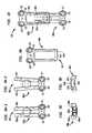
- FIG. 3 ais a top view of a first plate of an embodiment of the invention.
- FIG. 3 bis a top view of a second plate of an embodiment of the invention.
- FIG. 3 cis an end view of a first plate of an embodiment of the invention.
- FIG. 3 dis an end view of a second plate of an embodiment of the invention.
- FIG. 4is a top view of cooperating first and second plates of an embodiment of the invention.
- FIG. 5is a side view of a bone screw of a plate assembly of an embodiment of the invention.
- FIG. 6is a side view of a coupling element of a plate assembly of an embodiment of the invention.
- FIG. 7is a partial side cross sectional view of an assembled embodiment of the invention.
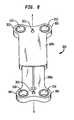
- FIG. 8is a perspective view of a plate assembly of another embodiment of the invention.
- FIG. 9 a 1is a top view of a first plate of a second embodiment of the invention showing prongs closed.
- FIG. 9 a 2is a top view of a first plate of a second embodiment of the invention showing prongs open.
- FIG. 9 bis a top view of a second plate of a second embodiment of the invention.
- FIG. 9 cis an end view of a first plate of a second embodiment of the invention.
- FIG. 9 dis an end view of a second plate of a second embodiment of the invention.
- FIG. 10is a top view of cooperating first and second plates of a second embodiment of the invention.
- FIGS. 3 a, 3 b, 3 c, 3 d and 4illustrate elements of a plate assembly 100 of an embodiment of the invention.
- FIG. 3 aillustrates a top view of a first longitudinal plate 100 a of the plate assembly 100 .
- the first plate 100 ahas an end 102 defined by longitudinal prongs 102 a, 102 b that are laterally adjacent one another. While two prongs are shown in this embodiment, and are shown as laterally adjacent one another, it is understood that a greater number of prongs and/or prongs that are adjacent one another in other configurations can be used without departing from the scope of the invention.
- FIG. 3 billustrates a top view of a second longitudinal plate 100 b of the plate assembly 100 .
- the second plate 100 bhas an end 104 that has a longitudinal bore 104 a that is adapted to receive the prongs 102 a, 102 b for longitudinal translation therein through a plurality of positions.
- FIG. 4illustrates a top view of the plate assembly 100 when the prongs 102 a, 102 b of the first plate 100 a are received within the bore 104 a of the second plate 100 b.
- the prongs 102 a, 102 bcan be inserted into the bore 104 a and translated longitudinally therein through one or more of the plurality of positions until the desired length of the plate assembly 100 is achieved by stopping the translation at one of the positions, such position establishing the desired relative position of the first plate 100 a to the second plate 100 b to achieve the desired length of the plate assembly 100 .
- the plates 100 a, 100 bmay be constructed of any suitably biocompatible material which has the structural strength and durability to withstand the cyclical loading associated with long term fixation to the spine.
- Materials which would be suitable for such applicationsinclude titanium alloys and steels.
- a specific titanium material which has been utilized in implants of the prior artinclude ASTM F-136 titanium alloy (Ti 6AL-4V). This material has enhanced mechanical properties including fatigue endurance and tensile strength, as compared with pure titanium.
- the plate assembly 100further includes a lock assembly for locking the prongs 102 a, 102 b within the bore 104 a at the selected position. Activation of the lock assembly secures the relative position of the plates 100 a, 100 b so that the desired length of the plate assembly 100 is fixed.
- FIG. 3 cillustrates an end view of the first plate 100 a.
- the lock assemblyincludes a threaded bore 100 d between the prongs 102 a, 102 b and a set screw 100 e passing between the prongs 102 a, 102 b and into the threaded bore 100 d.
- Rotation of the set screw 100 eadvances the set screw 100 e into the threaded bore 100 d, causing the prongs 102 a, 102 b to separate as the set screw 100 e passes between them as it advances.
- a head of the set screw 100 eincludes a recess that can be mated with a screwdriving tool and the screwdriving tool can be used to rotate the set screw 100 e within the threaded bore 100 d to advance the set screw 100 e until the prongs 102 a, 102 b separate.
- FIG. 3 dillustrates an end view of the second plate 100 b. It can be seen that the bore 104 a has an inner surface 104 b.
- FIG. 4illustrates a plan view of the plate assembly 100 when the prongs 102 a, 102 b are received within the bore 104 a.
- the prongs 102 a, 102 bare laterally adjacent one another and the lock assembly separates the prongs 102 a, 102 b to press them against the inner surface 104 b as described above.
- the compression of the prongs 102 a, 102 b against the inner surface 104 bsecures the position of the plates 100 a, 100 b relative to one another, thereby fixing the length of the plate assembly 100 .
- FIGS. 9 a 1 , 9 a 2 , 9 b, 9 c, 9 d and 10will now be discussed as describing a second embodiment of the present invention that is similar to the first embodiment shown in FIGS. 3 a-d and 4 in all material respects (and like elements are accordingly like numbered in FIGS. 9 a 1 , 9 a 2 , 9 b, 9 c, 9 d and 10 ) except that this second embodiment has a different lock assembly.
- the discussionwill then continue with respect to other aspects of the present invention, which apply to both embodiments, except where specifically noted.
- FIG. 9 cillustrates an end view of the first plate 100 a of the second embodiment, in which the lock assembly includes a cam assembly having a cam 900 that when placed in a first position (e.g., as shown in FIG. 9 a 1 which is a plan view of the plate assembly 100 of this second embodiment), does not press the prongs 102 a, 102 b against the inner surface 104 b, allowing the prongs 102 a, 102 b to longitudinally translate freely within the bore 104 a through a plurality of positions, and when placed in a second position (e.g., rotated 90 degrees with respect to the first position as shown in FIG.
- a first positione.g., as shown in FIG. 9 a 1 which is a plan view of the plate assembly 100 of this second embodiment
- a suitable cam 900would have an elongated cross-section at that portion 908 of the cam 900 that engages the prongs 102 a, 102 b for separation, such that, e.g., the width of the cam 900 at that portion 908 is smaller than the resting distance between the prongs 102 a, 102 b (the distance between the prongs 102 a, 102 b when they are not engaged by the cam 900 ), and the length of the cam 900 at that portion 908 is greater than the combination of the resting distance between the prongs 102 a, 102 b and the resting distances between each prong 102 a, 102 b and the inner surface 104 b (the distances between the prongs 102 a, 102 b and the inner surface 104 b when the prongs 102 a, 102 b are not engaged by the cam 900 ).
- a suitable cam 900would have at least one feature that maintains the cam 900 within the plate assembly 100 .
- a suitable featurecomprises flanges 906 that prevent the cam 900 from slipping out from between the prongs 102 a, 102 b.
- the flanges 906have a greater cross-section than the length of the portion 908 of the cam 900 , as shown.
- Another example of a suitable featurecomprises a rotatable mounting 902 of the cam 900 to the second plate 100 b and such that the cam 900 is located between the prongs 102 a, 102 b when the prongs 102 a, 102 b are longitudinally translated in the bore 104 a.
- such a cam 900could be made longitudinally translatable in the bore 104 a, e.g., on a track, so that it can be slid between the prongs 102 a, 102 b to any desired location therebetween, and so positionable at any desired prong separation location suitable for the length to which the plate assembly 100 has been adjusted.
- the mounting to the second plate 100 bwould also serve to maintain the cam 900 within the plate assembly 100 , and therefore would not require the cam 900 to have flanges 906 to maintain it within the plate assembly 100 .
- the cam 900when the cam 900 is in the first position, it preferably can be slid between the prongs 102 a, 102 b to any desired location therebetween, and so is positionable at any desired prong separation location suitable for the length to which the plate assembly 100 has been adjusted. Once the desired prong separation location has been reached, rotation of the cam 900 engages the portion 908 with the prongs 102 a, 102 b to maintain them against the inner surface 104 b.
- cam types and other rotatable mountingscan be used, and fall within the scope of the present invention.
- FIG. 9 dillustrates an end view of the second plate 100 b of this second embodiment, showing that the bore 104 a has the inner surface 104 b.
- FIG. 10illustrates a plan view of the plate assembly 100 of this second embodiment when the prongs 102 a, 102 b are received within the bore 104 a.
- the prongs 102 a, 102 bare laterally adjacent one another and when the cam 900 is in the first position (e.g., as shown in FIG. 9 a 1 ), the prongs 102 a, 102 b are not pressed against the inner surface 104 b, allowing the prongs 102 a, 102 b to longitudinally translate freely within the bore 104 a through a plurality of positions.
- the cam 900can be slid between the prongs 102 a, 102 b to the most advantageous position for engaging the prongs 102 a, 102 b, and can be turned.
- the turningcan be made possible, e.g., by a rotatable mounting of the cam 900 between the prongs 102 a, 102 b (e.g., the dimensions of the cam 900 discussed above make it possible to rotate the cam 900 between the prongs 102 a, 102 b, and an engageable feature 904 on the cam 900 that when rotated rotates the cam 900 .
- a suitable engageable feature 904is a screwdriver-receiving recess as shown.
- the cam 900When the cam 900 is turned enough to be placed in the second position (e.g., rotated 90 degrees with respect to the first position as shown in FIG. 9 a 2 ), the cam 900 separates the prongs 102 a, 102 b and presses them against the inner surface 104 b, preventing longitudinal translation of the prongs 102 a, 102 b within the bore 104 a, effectively locking the prongs 102 a, 102 b at the desired position.
- a slight lateral curvaturepreferably is imparted to the plate assembly 100 .
- the first plate 100 ahas a convex top surface 108 a and a concave bottom surface 109 a.
- the second plate 100 bhas a convex top surface 108 b and a concave bottom surface 109 b and the bore 104 a has a corresponding curvature so that it can receive the prongs 102 a, 102 b of the first plate 100 a.
- each plate 100 a, 100 bincludes a feature that can be used to couple the plate 100 a, 100 b to a body structure.
- each featurecomprises a pair of through holes.
- additional or alternative featuresmay be appropriate, including, for example, one or more hooks, rings, recesses, clips, and adhesives.
- a first pair of through holes 110extend fully through the first plate 100 a, from the top surface 108 a of the plate 100 a through to the bottom surface 109 a of the plate 100 a.
- a second pair of through holes 112having internal threading 113 , extend fully through the second plate 100 b, from the top surface 108 b of the plate 100 b through to the bottom surface 109 b of the plate 109 b.
- the embodiment shownfurther includes elements that can be used in conjunction with the features of the plates 100 a, 100 b to couple the plates 100 a, 100 b to the body structure.
- the elementsinclude screws and cooperative coupling elements. It should be understood that elements or tools other than the ones herein described can alternatively or additionally be used with the described or suggested features of the plates 100 a, 100 b to couple the plates 100 a, 100 b to the body structures.
- a screw of a type which is ideally suited for coupling the plates 100 a, 100 b to vertebral bonesis shown in a side view.
- the screw 120comprises a head portion 122 , a neck 124 , and a shaft 126 .
- the shaft 126is shown as having a tapered shape with a high pitch thread 128 .
- the specific choice of shaft features, such as thread pitch, or shaft diameter to thread diameter ratio, or overall shaft shape, etc.should be made by the physician with respect to the conditions of the patient's bone, however, the invention is compatible with a wide variety of shaft designs.
- the head portion 122 of the screw 120is semi-spherical and has a recess 130 . It is understood that the semi-spherical shape is necessarily a section of a sphere, greater in extent than a hemisphere, and exhibits an external contour which is equidistant from a center point of the head.
- the major cross-section of the semi-spherical head 122includes at least 270 degrees of a circle.
- the recess 130defines a receiving locus for the application of a torque for driving the screw 120 into the bone.
- the specific shape of the recess 122may be chosen to cooperate with any suitable screwdriving tool.
- the recess 130may comprise a slot for a flatheaded screwdriver, a crossed recess for a phillips head screwdriver, or most preferably, a hexagonally shaped hole for receiving an allen wrench.
- the recess 130be co-axial with the general elongate axis of the screw 120 , and most particularly with respect to the shaft 126 . Having the axes of the recess 130 and the shaft 126 co-linear facilitates step of inserting the screw 120 into the bone.
- the semi-spherical head 122is connected to the shaft 126 at a neck portion 124 . While it is preferable that the diameter of the shaft 126 be less than the radius of the semi-spherical head 122 , it is also preferable that the neck 124 of the screw 120 be narrower than the widest portion of the shaft 126 . This preferable dimension permits the screw to be inserted at a variety of angles while still permitting a coupling element (as described with respect to FIG. 6) to be screwed into the appropriate hole 110 or 112 of the plate assembly 100 and remain coupled to the head 122 .
- this embodimentfurther includes additional elements that can be used in conjunction with the features of the plates 100 a, 100 b to couple the plates 100 a, 100 b to the body structure or structures.
- a coupling element of the inventionis shown in side view, wherein phantom lines show the interior structure of the element along a diametrical cross section.
- the coupling element 132comprises a cylindrical socket having an external threading 134 .
- the external threading 134 and the diameter of the exterior of the cylindrical socketis designed to mate with threading 111 or 113 of the holes 110 or 112 of the plate assembly 100 , so that the coupling element 132 may be screwed into the plate assembly 100 .
- the uppermost thread 135be designed to crush-lock the coupling element 132 into the hole 110 or 112 . Once screwed into the plate assembly 100 , and locked down, the top surface 136 of the coupling element 132 and the respective top surface 108 a, 108 b of the plate assembly 100 present a flush external surface.
- the top surface 136 of the coupling element 132which is shown in FIG. 6 further comprises a through hole 138 , which extends from the top surface 136 to an interior semi-spherical volume 140 .
- This through hole 138is designed such that the screwdriving tool which is used to insert the screw 120 into the body structure may access and rotate the screw 120 through the coupling element 132 .
- the interior semi-spherical volume 140is ideally suited for holding the head 122 of the screw 120 , and permitting the screw 120 to rotate through a range of angles.
- the coupling element 132has a bottom 142 which has a circular hole (enumerated as 143 on the bottom surface of the side view of the coupling element in FIG. 6) which forms the bottom entrance into the interior semi-spherical volume 140 . It is understood that the head 122 of the screw 120 is held within the interior semi-spherical volume 140 by the annular rim, or support lip, 144 of the bottom 142 of the coupling element 132 . This annular support lip 144 defines the circular opening 143 which has a diameter less than the diameter of the semi-spherical head 122 of the screw 120 .
- the lower portion of the coupling element 132comprise slots 146 so that the physician may insert the head 122 into the interior volume 140 .
- These slots 146permit the lower portion of the coupling element 132 to expand to accept the inserted head 122 , but is secured from releasing the head 122 once the coupling element 132 is screwed into the plate assembly 100 .
- the holes 110 a or 112 a(as shown in phantom in FIG. 7) of the plate assembly 100 are tapered inward with respect to insertion direction.
- the step of screwing the coupling element 132 into the hole 110 a or 112 acauses the slots 146 to be compressed and, correspondingly, for the bottom entrance 143 and the annular lip 144 to lock the screw head 122 into position.
- the coupling element 132it is also possible for the coupling element 132 to be formed in a manner whereby the lower portion does not have to include an expanding entrance 143 .
- the coupling element 132would necessarily be formed of two separate pieces which would be joined together about the head 122 of the screw 120 .
- the top surface 136 of the coupling element 132it is preferred than the top surface 136 of the coupling element 132 have features, such as holes 148 , allowing a second screwdriving tool to easily insert the element 132 into the threaded holes 110 , 100 a or 112 , 112 a of the plate assembly 100 .
- FIG. 7a partial side cross sectional view of a plate assembly 100 of the invention is shown.
- the operative steps of implanting this plate assembly 100 and affixing it to, for example, a pair of vertebral bonesbegins with preparing the bones through surgical tissue resection and exposure.
- the prongs 102 a, 102 b of the first longitudinal plate 100 aare inserted into the bore 104 a of the second longitudinal plate 100 b and translated therein until the desired length of the plate assembly 100 is achieved. More specifically, the surgeon determines, after inspection of the vertebral bones to be secured, how far apart the holes 110 of the first longitudinal plate 100 a must be spaced from the holes 112 of the second longitudinal plate 100 b in order for the plate assembly 100 to be properly coupled to the vertebral bones to be clinically effective.
- the surgeonuses a screwdriving tool to rotate the set screw 100 e within the threaded bore 100 d to advance the set screw 100 e until the prongs 102 a, 102 b separate and press against the inner surface 104 b of the bore 104 a.
- the compression of the prongs 102 a, 102 b against the inner surface 104 bsecures the position of the plates 100 a, 100 b relative to one another, thereby fixing the length of the plate assembly 100 .
- the surgeonis able to use the screwdriving tool to reverse rotate the set screw 100 e within the threaded bore 100 d to retract the set screw 100 e and thereby return the prongs 102 a, 102 b back together so that they no longer press against the inner surface 104 b of the bore 104 a so that the prongs 102 a, 102 b may again freely translate within the bore 104 a.
- This functionalityallows the surgeon to readjust the length of the plate assembly 100 if the surgeon's first setting of the length is not correct or is undesirable.
- the surgeonis able to use the screwdriving tool to reverse rotate the cam 900 between the prongs 102 a, 102 b to return the prongs 102 a, 102 b back together so that they no longer press against the inner surface 104 b of the bore 104 a so that the prongs 102 a, 102 b may again freely translate within the bore 104 a.
- This functionalityallows the surgeon to readjust the length of the plate assembly 100 if the surgeon's first setting of the length is not correct or is undesirable.
- the plate assembly 100is positioned against the bones and pre-drill holes are made at the desired insertion angle for the screw 120 .
- Screw 120 and coupling element 132are then placed together so that the head 122 is within the interior volume 140 , whereby the two elements are able to rotate freely with respect to one another, but are nonetheless coupled.
- the recess 130 in the screw 120 and the through hole 138 of the coupling element 132are aligned at first, and an appropriate screwdriving tool is used to insert the screw 120 through the proper hole 110 or 112 ( 110 a or 112 a ) and into the pre-drilled hole in the bone.
- an appropriate screwdriving toolis used to insert the screw 120 through the proper hole 110 or 112 ( 110 a or 112 a ) and into the pre-drilled hole in the bone.
- Complete insertion of the coupling element 132 to the plate assembly 100preferably locks the element 132 to the plate assembly 100 , in addition to locking the screw 120 and plate assembly 100 to the bone.
- corresponding holes 110 or 112may be tapered; the complete insertion of the coupling element 132 into the hole 110 or 112 therein having the additional benefit of locking the angle of the screw 120 .
- This plate assembly 300comprises a first plate 300 a corresponding to the first plate 100 a of the plate assembly 100 and a second plate 300 b corresponding to the second plate 100 b of the plate assembly 100 .
- the first plate 300 ahas through holes 310 and a bottom surface 309 a and the second plate 300 b has through holes 312 and a bottom surface 309 b.
- the plate assembly 300further includes at least one feature protruding from one of the bottom surfaces 309 a, 309 b for removable and temporary fixation of the plate assembly 300 to a vertebral bone.
- the featureis a spike.
- other featurescan additionally or alternatively be used to achieve this functionality without departing from the scope of the invention.
- one spike element 301protrudes from each of the bottom surfaces 309 a, 309 b.
- each spike 301is positioned between the pair of holes 310 or 312 , on center line A—A.
- These spikesallow the plate assembly 300 to be temporarily, and easily removably, fixed to vertebral bones during the steps of pre-drilling and insertion of the screws 120 through the holes 310 , 312 and into the vertebral bones. This is a desirable operational advantage, as it frees one hand of the surgeon and/or removes extra tools from the surgical site.
- the spikes 301positioned along the center line A—A for plate assemblies 300 which have a radius of curvature which is equal to or greater than that of the vertebral bodies such as, for example, vertebral bones (i.e., not as curved as the bone). Having the spikes 301 along the center line ensures that the plate assembly 300 can be removably fixed to the bone by simply applying an insertion force against the plate assembly 300 and driving the spikes 301 into the bone. It is understood that for implants wherein the plate assembly 300 has a smaller radius of curvature than the bone, it would be desirable to position the spikes 301 at edges 303 of the plate assembly 300 .
Landscapes
- Health & Medical Sciences (AREA)
- Orthopedic Medicine & Surgery (AREA)
- Life Sciences & Earth Sciences (AREA)
- Surgery (AREA)
- Neurology (AREA)
- Heart & Thoracic Surgery (AREA)
- Engineering & Computer Science (AREA)
- Biomedical Technology (AREA)
- Nuclear Medicine, Radiotherapy & Molecular Imaging (AREA)
- Medical Informatics (AREA)
- Molecular Biology (AREA)
- Animal Behavior & Ethology (AREA)
- General Health & Medical Sciences (AREA)
- Public Health (AREA)
- Veterinary Medicine (AREA)
- Prostheses (AREA)
- Surgical Instruments (AREA)
Abstract
Description
Claims (18)
Priority Applications (3)
| Application Number | Priority Date | Filing Date | Title |
|---|---|---|---|
| US10/075,689US6666867B2 (en) | 2001-02-15 | 2002-02-13 | Longitudinal plate assembly having an adjustable length |
| US10/092,893US6689134B2 (en) | 2002-02-13 | 2002-03-07 | Longitudinal plate assembly having an adjustable length |
| US10/725,307US20040106924A1 (en) | 2001-02-15 | 2003-12-01 | Longitudinal plate assembly having an adjustable length |
Applications Claiming Priority (2)
| Application Number | Priority Date | Filing Date | Title |
|---|---|---|---|
| US09/789,938US6402756B1 (en) | 2001-02-15 | 2001-02-15 | Longitudinal plate assembly having an adjustable length |
| US10/075,689US6666867B2 (en) | 2001-02-15 | 2002-02-13 | Longitudinal plate assembly having an adjustable length |
Related Parent Applications (2)
| Application Number | Title | Priority Date | Filing Date |
|---|---|---|---|
| US09/789,938ContinuationUS6402756B1 (en) | 2001-02-15 | 2001-02-15 | Longitudinal plate assembly having an adjustable length |
| US09/789,938Continuation-In-PartUS6402756B1 (en) | 2001-02-15 | 2001-02-15 | Longitudinal plate assembly having an adjustable length |
Related Child Applications (2)
| Application Number | Title | Priority Date | Filing Date |
|---|---|---|---|
| US10/092,893ContinuationUS6689134B2 (en) | 2002-02-13 | 2002-03-07 | Longitudinal plate assembly having an adjustable length |
| US10/725,307ContinuationUS20040106924A1 (en) | 2001-02-15 | 2003-12-01 | Longitudinal plate assembly having an adjustable length |
Publications (2)
| Publication Number | Publication Date |
|---|---|
| US20020111630A1 US20020111630A1 (en) | 2002-08-15 |
| US6666867B2true US6666867B2 (en) | 2003-12-23 |
Family
ID=70544982
Family Applications (3)
| Application Number | Title | Priority Date | Filing Date |
|---|---|---|---|
| US10/075,689Expired - LifetimeUS6666867B2 (en) | 2001-02-15 | 2002-02-13 | Longitudinal plate assembly having an adjustable length |
| US10/092,893Expired - LifetimeUS6689134B2 (en) | 2002-02-13 | 2002-03-07 | Longitudinal plate assembly having an adjustable length |
| US10/725,307AbandonedUS20040106924A1 (en) | 2001-02-15 | 2003-12-01 | Longitudinal plate assembly having an adjustable length |
Family Applications After (2)
| Application Number | Title | Priority Date | Filing Date |
|---|---|---|---|
| US10/092,893Expired - LifetimeUS6689134B2 (en) | 2002-02-13 | 2002-03-07 | Longitudinal plate assembly having an adjustable length |
| US10/725,307AbandonedUS20040106924A1 (en) | 2001-02-15 | 2003-12-01 | Longitudinal plate assembly having an adjustable length |
Country Status (1)
| Country | Link |
|---|---|
| US (3) | US6666867B2 (en) |
Cited By (51)
| Publication number | Priority date | Publication date | Assignee | Title |
|---|---|---|---|---|
| US20040106924A1 (en)* | 2001-02-15 | 2004-06-03 | Ralph James D. | Longitudinal plate assembly having an adjustable length |
| US20040133207A1 (en)* | 2002-10-11 | 2004-07-08 | Abdou M. Samy | Distraction screw for skeletal surgery and method of use |
| US20050124996A1 (en)* | 2001-02-23 | 2005-06-09 | Hearn James P. | Sternum fixation device |
| US20050130092A1 (en)* | 2002-01-23 | 2005-06-16 | Roger Minoretti | Distracting device for orthodontic/orosurgical purposes on the lower jaw |
| US20050177163A1 (en)* | 2003-12-29 | 2005-08-11 | Abdou M. S. | Plating system for bone fixation and method of implantation |
| US20060100625A1 (en)* | 2004-10-28 | 2006-05-11 | Ralph James D | Adjustable bone plate |
| US20060116683A1 (en)* | 2004-12-01 | 2006-06-01 | Barrall Benjamin S | Unidirectional translation system for bone fixation |
| US20060167457A1 (en)* | 2005-01-21 | 2006-07-27 | Loubert Suddaby | Orthopedic fusion plate having both active and passive subsidence controlling features |
| US20060179979A1 (en)* | 2005-02-01 | 2006-08-17 | Dees Roger R Jr | Lockable orientation stylus |
| US20060229615A1 (en)* | 2005-02-18 | 2006-10-12 | Abdou M S | Devices and methods for dynamic fixation of skeletal structure |
| US20060271052A1 (en)* | 2005-05-12 | 2006-11-30 | Stern Joseph D | Revisable anterior cervical plating system |
| US20070055250A1 (en)* | 2005-07-11 | 2007-03-08 | Kamran Aflatoon | Cervical plates with spacer mechanism |
| US20070123881A1 (en)* | 2005-10-26 | 2007-05-31 | Ralph James D | Off-set bone plates |
| US20070173841A1 (en)* | 2006-01-18 | 2007-07-26 | Ralph James D | Adjustable bone plate |
| US20070213729A1 (en)* | 2006-03-08 | 2007-09-13 | Sdgi Holdings, Inc. | Flexible bone plates and methods for dynamic spinal stabilization |
| US7306605B2 (en) | 2003-10-02 | 2007-12-11 | Zimmer Spine, Inc. | Anterior cervical plate |
| US20080058810A1 (en)* | 2003-01-10 | 2008-03-06 | Abdou M S | Bone screw systems and methods of use |
| US20080108998A1 (en)* | 2006-11-02 | 2008-05-08 | Warsaw Orthopedic Inc. | Uni-directional ratcheting bone plate assembly |
| US20090076509A1 (en)* | 2007-09-13 | 2009-03-19 | Stryker Spine | Dynamic cervical plate |
| US20090163960A1 (en)* | 2007-11-21 | 2009-06-25 | Lawrence Binder | Cervical spine stabilization system with extendable plates |
| US7618443B2 (en) | 2004-06-14 | 2009-11-17 | Abdou M Samy | Occipito fixation system and method of use |
| US7666185B2 (en) | 2003-09-03 | 2010-02-23 | Synthes Usa, Llc | Translatable carriage fixation system |
| US7727266B2 (en) | 2004-06-17 | 2010-06-01 | Warsaw Orthopedic, Inc. | Method and apparatus for retaining screws in a plate |
| US20100234850A1 (en)* | 2005-02-01 | 2010-09-16 | Smith And Nephew, Inc. | Lockable Orientation Instrument Assembly |
| US20110054528A1 (en)* | 2001-06-04 | 2011-03-03 | Michelson Gary K | Dynamic plate system having moveable segments |
| US20110137314A1 (en)* | 2009-07-06 | 2011-06-09 | Zimmer, Gmbh | Periprosthetic bone plates |
| US7985224B2 (en) | 2001-06-04 | 2011-07-26 | Warsaw Orthopedic, Inc. | Method for installation of dynamic, single-lock anterior cervical plate system having non-detachably fastened and moveable segments |
| US20110218533A1 (en)* | 2010-03-08 | 2011-09-08 | Bernard Prandi | Radius-plate assembly |
| US20110218534A1 (en)* | 2010-03-08 | 2011-09-08 | Bernard Prandi | Adjustable-angle radius plate |
| US8070749B2 (en) | 2005-05-12 | 2011-12-06 | Stern Joseph D | Revisable anterior cervical plating system |
| US20120095466A1 (en)* | 2010-10-19 | 2012-04-19 | Biomet Manufacturing Corp. | Orthopedic Plate Assembly for a Distal Radius Having Re-Contouring Features and Method for Using Same |
| US8241341B2 (en) | 2009-03-20 | 2012-08-14 | Spinal Usa, Inc. | Pedicle screws and methods of using the same |
| US8262710B2 (en)* | 2006-10-24 | 2012-09-11 | Aesculap Implant Systems, Llc | Dynamic stabilization device for anterior lower lumbar vertebral fusion |
| US8425514B2 (en) | 2008-06-25 | 2013-04-23 | Westmark Medical, Llc. | Spinal fixation device |
| US8562656B2 (en) | 2010-10-15 | 2013-10-22 | Warsaw Orrthopedic, Inc. | Retaining mechanism |
| US8876874B2 (en) | 2006-08-21 | 2014-11-04 | M. Samy Abdou | Bone screw systems and methods of use |
| US9089343B2 (en) | 2005-10-03 | 2015-07-28 | Smith & Nephew, Inc. | Locking instrument assembly |
| US9408646B2 (en) | 2003-09-03 | 2016-08-09 | DePuy Synthes Products, Inc. | Bone plate with captive clips |
| US9867714B1 (en) | 2011-09-23 | 2018-01-16 | Samy Abdou | Spinal fixation devices and methods of use |
| US10111757B2 (en) | 2012-10-22 | 2018-10-30 | Cogent Spine, LLC | Devices and methods for spinal stabilization and instrumentation |
| US10441329B2 (en) | 2013-10-28 | 2019-10-15 | Jace Medical, Llc | Orthopedic fixation device, system and method |
| US10543107B2 (en) | 2009-12-07 | 2020-01-28 | Samy Abdou | Devices and methods for minimally invasive spinal stabilization and instrumentation |
| US10548740B1 (en) | 2016-10-25 | 2020-02-04 | Samy Abdou | Devices and methods for vertebral bone realignment |
| US10695105B2 (en) | 2012-08-28 | 2020-06-30 | Samy Abdou | Spinal fixation devices and methods of use |
| US10857003B1 (en) | 2015-10-14 | 2020-12-08 | Samy Abdou | Devices and methods for vertebral stabilization |
| US10918498B2 (en) | 2004-11-24 | 2021-02-16 | Samy Abdou | Devices and methods for inter-vertebral orthopedic device placement |
| US10973648B1 (en) | 2016-10-25 | 2021-04-13 | Samy Abdou | Devices and methods for vertebral bone realignment |
| US11006982B2 (en) | 2012-02-22 | 2021-05-18 | Samy Abdou | Spinous process fixation devices and methods of use |
| US11179248B2 (en) | 2018-10-02 | 2021-11-23 | Samy Abdou | Devices and methods for spinal implantation |
| US11331125B1 (en)* | 2021-10-07 | 2022-05-17 | Ortho Inventions, Llc | Low profile rod-to-rod coupler |
| US12185996B2 (en) | 2014-08-20 | 2025-01-07 | Biomet Microfixation, Llc | Implant positioning devices and methods |
Families Citing this family (193)
| Publication number | Priority date | Publication date | Assignee | Title |
|---|---|---|---|---|
| US7833250B2 (en) | 2004-11-10 | 2010-11-16 | Jackson Roger P | Polyaxial bone screw with helically wound capture connection |
| US6726689B2 (en)* | 2002-09-06 | 2004-04-27 | Roger P. Jackson | Helical interlocking mating guide and advancement structure |
| US8377100B2 (en)* | 2000-12-08 | 2013-02-19 | Roger P. Jackson | Closure for open-headed medical implant |
| US20050234458A1 (en)* | 2004-04-19 | 2005-10-20 | Huebner Randall J | Expanded stabilization of bones |
| US20050240187A1 (en)* | 2004-04-22 | 2005-10-27 | Huebner Randall J | Expanded fixation of bones |
| US7862587B2 (en) | 2004-02-27 | 2011-01-04 | Jackson Roger P | Dynamic stabilization assemblies, tool set and method |
| US8353932B2 (en) | 2005-09-30 | 2013-01-15 | Jackson Roger P | Polyaxial bone anchor assembly with one-piece closure, pressure insert and plastic elongate member |
| US10729469B2 (en) | 2006-01-09 | 2020-08-04 | Roger P. Jackson | Flexible spinal stabilization assembly with spacer having off-axis core member |
| US8292926B2 (en) | 2005-09-30 | 2012-10-23 | Jackson Roger P | Dynamic stabilization connecting member with elastic core and outer sleeve |
| US10258382B2 (en) | 2007-01-18 | 2019-04-16 | Roger P. Jackson | Rod-cord dynamic connection assemblies with slidable bone anchor attachment members along the cord |
| CA2443429C (en) | 2001-06-04 | 2010-08-10 | Gary Karlin Michelson | Anterior cervical plate system having vertebral body engaging anchors, connecting plate, and method for installation thereof |
| US7186256B2 (en)* | 2001-06-04 | 2007-03-06 | Warsaw Orthopedic, Inc. | Dynamic, modular, single-lock anterior cervical plate system having assembleable and movable segments |
| US7044952B2 (en)* | 2001-06-06 | 2006-05-16 | Sdgi Holdings, Inc. | Dynamic multilock anterior cervical plate system having non-detachably fastened and moveable segments |
| US7041105B2 (en)* | 2001-06-06 | 2006-05-09 | Sdgi Holdings, Inc. | Dynamic, modular, multilock anterior cervical plate system having detachably fastened assembleable and moveable segments |
| US7766947B2 (en) | 2001-10-31 | 2010-08-03 | Ortho Development Corporation | Cervical plate for stabilizing the human spine |
| US7070599B2 (en) | 2002-07-24 | 2006-07-04 | Paul Kamaljit S | Bone support assembly |
| US6755833B1 (en) | 2001-12-14 | 2004-06-29 | Kamaljit S. Paul | Bone support assembly |
| CA2471843C (en)* | 2001-12-24 | 2011-04-12 | Synthes (U.S.A.) | Device for osteosynthesis |
| US6932820B2 (en)* | 2002-01-08 | 2005-08-23 | Said G. Osman | Uni-directional dynamic spinal fixation device |
| US9101422B2 (en)* | 2002-02-01 | 2015-08-11 | Zimmer Spine, Inc. | Spinal plate system for stabilizing a portion of a spine |
| US20040019353A1 (en) | 2002-02-01 | 2004-01-29 | Freid James M. | Spinal plate system for stabilizing a portion of a spine |
| US8282673B2 (en)* | 2002-09-06 | 2012-10-09 | Jackson Roger P | Anti-splay medical implant closure with multi-surface removal aperture |
| US20060009773A1 (en)* | 2002-09-06 | 2006-01-12 | Jackson Roger P | Helical interlocking mating guide and advancement structure |
| US8257402B2 (en)* | 2002-09-06 | 2012-09-04 | Jackson Roger P | Closure for rod receiving orthopedic implant having left handed thread removal |
| US8876868B2 (en)* | 2002-09-06 | 2014-11-04 | Roger P. Jackson | Helical guide and advancement flange with radially loaded lip |
| WO2006052796A2 (en) | 2004-11-10 | 2006-05-18 | Jackson Roger P | Helical guide and advancement flange with break-off extensions |
| US20040158250A1 (en)* | 2002-09-13 | 2004-08-12 | Chappuis James L. | Anterior cervical corpectomy plate |
| US8172885B2 (en) | 2003-02-05 | 2012-05-08 | Pioneer Surgical Technology, Inc. | Bone plate system |
| US8540753B2 (en) | 2003-04-09 | 2013-09-24 | Roger P. Jackson | Polyaxial bone screw with uploaded threaded shank and method of assembly and use |
| US6716214B1 (en) | 2003-06-18 | 2004-04-06 | Roger P. Jackson | Polyaxial bone screw with spline capture connection |
| US7621918B2 (en) | 2004-11-23 | 2009-11-24 | Jackson Roger P | Spinal fixation tool set and method |
| US7377923B2 (en) | 2003-05-22 | 2008-05-27 | Alphatec Spine, Inc. | Variable angle spinal screw assembly |
| US8257398B2 (en)* | 2003-06-18 | 2012-09-04 | Jackson Roger P | Polyaxial bone screw with cam capture |
| US7766915B2 (en) | 2004-02-27 | 2010-08-03 | Jackson Roger P | Dynamic fixation assemblies with inner core and outer coil-like member |
| US7967850B2 (en) | 2003-06-18 | 2011-06-28 | Jackson Roger P | Polyaxial bone anchor with helical capture connection, insert and dual locking assembly |
| US8377102B2 (en) | 2003-06-18 | 2013-02-19 | Roger P. Jackson | Polyaxial bone anchor with spline capture connection and lower pressure insert |
| US8398682B2 (en)* | 2003-06-18 | 2013-03-19 | Roger P. Jackson | Polyaxial bone screw assembly |
| US8366753B2 (en)* | 2003-06-18 | 2013-02-05 | Jackson Roger P | Polyaxial bone screw assembly with fixed retaining structure |
| US20100211114A1 (en)* | 2003-06-18 | 2010-08-19 | Jackson Roger P | Polyaxial bone anchor with shelf capture connection |
| US8137386B2 (en) | 2003-08-28 | 2012-03-20 | Jackson Roger P | Polyaxial bone screw apparatus |
| US7776067B2 (en) | 2005-05-27 | 2010-08-17 | Jackson Roger P | Polyaxial bone screw with shank articulation pressure insert and method |
| US8092500B2 (en)* | 2007-05-01 | 2012-01-10 | Jackson Roger P | Dynamic stabilization connecting member with floating core, compression spacer and over-mold |
| US8926670B2 (en) | 2003-06-18 | 2015-01-06 | Roger P. Jackson | Polyaxial bone screw assembly |
| US6945975B2 (en)* | 2003-07-07 | 2005-09-20 | Aesculap, Inc. | Bone fixation assembly and method of securement |
| US7763056B2 (en)* | 2003-08-18 | 2010-07-27 | Dalton Brian E | Cervical compression plate assembly |
| US7763052B2 (en)* | 2003-12-05 | 2010-07-27 | N Spine, Inc. | Method and apparatus for flexible fixation of a spine |
| US7137985B2 (en)* | 2003-09-24 | 2006-11-21 | N Spine, Inc. | Marking and guidance method and system for flexible fixation of a spine |
| US7815665B2 (en) | 2003-09-24 | 2010-10-19 | N Spine, Inc. | Adjustable spinal stabilization system |
| US20050203513A1 (en)* | 2003-09-24 | 2005-09-15 | Tae-Ahn Jahng | Spinal stabilization device |
| US8979900B2 (en) | 2003-09-24 | 2015-03-17 | DePuy Synthes Products, LLC | Spinal stabilization device |
| US7527638B2 (en) | 2003-12-16 | 2009-05-05 | Depuy Spine, Inc. | Methods and devices for minimally invasive spinal fixation element placement |
| US7179261B2 (en) | 2003-12-16 | 2007-02-20 | Depuy Spine, Inc. | Percutaneous access devices and bone anchor assemblies |
| US11419642B2 (en) | 2003-12-16 | 2022-08-23 | Medos International Sarl | Percutaneous access devices and bone anchor assemblies |
| US8182518B2 (en)* | 2003-12-22 | 2012-05-22 | Life Spine, Inc. | Static and dynamic cervical plates and cervical plate constructs |
| US7678137B2 (en) | 2004-01-13 | 2010-03-16 | Life Spine, Inc. | Pedicle screw constructs for spine fixation systems |
| US20050177160A1 (en)* | 2004-02-10 | 2005-08-11 | Baynham Bret O. | Dynamic cervical plate |
| US8002809B2 (en)* | 2004-02-10 | 2011-08-23 | Atlas Spine, Inc. | Dynamic cervical plate |
| US8328854B2 (en)* | 2004-02-10 | 2012-12-11 | Atlas Spine, Inc. | Cervical plate ratchet pedicle screws |
| US7815666B2 (en)* | 2004-02-10 | 2010-10-19 | Atlas Spine, Inc. | Dynamic cervical plate |
| US7740649B2 (en) | 2004-02-26 | 2010-06-22 | Pioneer Surgical Technology, Inc. | Bone plate system and methods |
| US8900277B2 (en) | 2004-02-26 | 2014-12-02 | Pioneer Surgical Technology, Inc. | Bone plate system |
| US8152810B2 (en) | 2004-11-23 | 2012-04-10 | Jackson Roger P | Spinal fixation tool set and method |
| US7160300B2 (en) | 2004-02-27 | 2007-01-09 | Jackson Roger P | Orthopedic implant rod reduction tool set and method |
| US11241261B2 (en) | 2005-09-30 | 2022-02-08 | Roger P Jackson | Apparatus and method for soft spinal stabilization using a tensionable cord and releasable end structure |
| JP2007525274A (en) | 2004-02-27 | 2007-09-06 | ロジャー・ピー・ジャクソン | Orthopedic implant rod reduction instrument set and method |
| US20050209593A1 (en)* | 2004-03-06 | 2005-09-22 | Depuy Spine, Inc. | Flexible anterior cervical plate |
| US7942913B2 (en)* | 2004-04-08 | 2011-05-17 | Ebi, Llc | Bone fixation device |
| US7744635B2 (en)* | 2004-06-09 | 2010-06-29 | Spinal Generations, Llc | Spinal fixation system |
| US7938848B2 (en)* | 2004-06-09 | 2011-05-10 | Life Spine, Inc. | Spinal fixation system |
| US7651502B2 (en) | 2004-09-24 | 2010-01-26 | Jackson Roger P | Spinal fixation tool set and method for rod reduction and fastener insertion |
| US9615866B1 (en) | 2004-10-18 | 2017-04-11 | Nuvasive, Inc. | Surgical fixation system and related methods |
| US8926672B2 (en) | 2004-11-10 | 2015-01-06 | Roger P. Jackson | Splay control closure for open bone anchor |
| US8444681B2 (en) | 2009-06-15 | 2013-05-21 | Roger P. Jackson | Polyaxial bone anchor with pop-on shank, friction fit retainer and winged insert |
| WO2006057837A1 (en) | 2004-11-23 | 2006-06-01 | Jackson Roger P | Spinal fixation tool attachment structure |
| US8308782B2 (en) | 2004-11-23 | 2012-11-13 | Jackson Roger P | Bone anchors with longitudinal connecting member engaging inserts and closures for fixation and optional angulation |
| US9980753B2 (en) | 2009-06-15 | 2018-05-29 | Roger P Jackson | pivotal anchor with snap-in-place insert having rotation blocking extensions |
| US7875065B2 (en)* | 2004-11-23 | 2011-01-25 | Jackson Roger P | Polyaxial bone screw with multi-part shank retainer and pressure insert |
| US9168069B2 (en) | 2009-06-15 | 2015-10-27 | Roger P. Jackson | Polyaxial bone anchor with pop-on shank and winged insert with lower skirt for engaging a friction fit retainer |
| US9216041B2 (en) | 2009-06-15 | 2015-12-22 | Roger P. Jackson | Spinal connecting members with tensioned cords and rigid sleeves for engaging compression inserts |
| US7527640B2 (en)* | 2004-12-22 | 2009-05-05 | Ebi, Llc | Bone fixation system |
| US7901437B2 (en) | 2007-01-26 | 2011-03-08 | Jackson Roger P | Dynamic stabilization member with molded connection |
| US10076361B2 (en) | 2005-02-22 | 2018-09-18 | Roger P. Jackson | Polyaxial bone screw with spherical capture, compression and alignment and retention structures |
| US8163261B2 (en)* | 2005-04-05 | 2012-04-24 | Voltaix, Llc | System and method for making Si2H6 and higher silanes |
| US7749256B2 (en)* | 2005-04-05 | 2010-07-06 | Warsaw Orthopedic, Inc. | Ratcheting fixation plate |
| US20060259141A1 (en) | 2005-05-13 | 2006-11-16 | Walter Lorenz Surgical, Inc. | Pectus bar stabilizer |
| US7955364B2 (en)* | 2005-09-21 | 2011-06-07 | Ebi, Llc | Variable angle bone fixation assembly |
| US8105368B2 (en) | 2005-09-30 | 2012-01-31 | Jackson Roger P | Dynamic stabilization connecting member with slitted core and outer sleeve |
| KR101246113B1 (en)* | 2005-10-25 | 2013-03-20 | 앤썸 오르소패딕스, 엘엘씨 | Bone fastening assembly and bushing and screw for use therewith |
| US8192449B2 (en)* | 2005-10-25 | 2012-06-05 | Brainlab Ag | Non-penetrating fixing device |
| US9119677B2 (en) | 2005-12-09 | 2015-09-01 | DePuy Synthes Products, Inc. | Spinal plate and drill guide |
| US7704271B2 (en)* | 2005-12-19 | 2010-04-27 | Abdou M Samy | Devices and methods for inter-vertebral orthopedic device placement |
| US8100952B2 (en)* | 2005-12-22 | 2012-01-24 | Anthem Orthopaedics Llc | Drug delivering bone plate and method and targeting device for use therewith |
| EP1971282A2 (en) | 2006-01-10 | 2008-09-24 | Life Spine, Inc. | Pedicle screw constructs and spinal rod attachment assemblies |
| WO2007098188A2 (en)* | 2006-02-21 | 2007-08-30 | Life Spine, Inc. | Structure for joining and retaining multi-part orthopedic implants |
| US7695500B2 (en)* | 2006-03-10 | 2010-04-13 | Custom Spine, Inc. | Polyaxial occipital plate |
| US7776070B2 (en) | 2006-08-02 | 2010-08-17 | Warsaw Orthopedic, Inc. | Occipital plating systems and methods |
| US20080033438A1 (en)* | 2006-08-04 | 2008-02-07 | Roy Frizzell | Cervical Saddle Plate |
| DE102006042277B4 (en)* | 2006-09-08 | 2011-07-28 | MEDXPERT GmbH, 79423 | Implant for osteosynthesis, fixation and stabilization of long bones and implant system |
| US20080147122A1 (en)* | 2006-10-12 | 2008-06-19 | Jackson Roger P | Dynamic stabilization connecting member with molded inner segment and surrounding external elastomer |
| CA2670988C (en) | 2006-12-08 | 2014-03-25 | Roger P. Jackson | Tool system for dynamic spinal implants |
| US8366745B2 (en) | 2007-05-01 | 2013-02-05 | Jackson Roger P | Dynamic stabilization assembly having pre-compressed spacers with differential displacements |
| US8475498B2 (en) | 2007-01-18 | 2013-07-02 | Roger P. Jackson | Dynamic stabilization connecting member with cord connection |
| US10792074B2 (en) | 2007-01-22 | 2020-10-06 | Roger P. Jackson | Pivotal bone anchor assemly with twist-in-place friction fit insert |
| US8012177B2 (en)* | 2007-02-12 | 2011-09-06 | Jackson Roger P | Dynamic stabilization assembly with frusto-conical connection |
| WO2008115981A1 (en)* | 2007-03-19 | 2008-09-25 | Alpinespine Llc | Active compression orthopedic plate system and method for using the same |
| US8979904B2 (en) | 2007-05-01 | 2015-03-17 | Roger P Jackson | Connecting member with tensioned cord, low profile rigid sleeve and spacer with torsion control |
| US10383660B2 (en) | 2007-05-01 | 2019-08-20 | Roger P. Jackson | Soft stabilization assemblies with pretensioned cords |
| US7942909B2 (en) | 2009-08-13 | 2011-05-17 | Ortho Innovations, Llc | Thread-thru polyaxial pedicle screw system |
| US7947065B2 (en) | 2008-11-14 | 2011-05-24 | Ortho Innovations, Llc | Locking polyaxial ball and socket fastener |
| US7951173B2 (en)* | 2007-05-16 | 2011-05-31 | Ortho Innovations, Llc | Pedicle screw implant system |
| US7942911B2 (en) | 2007-05-16 | 2011-05-17 | Ortho Innovations, Llc | Polyaxial bone screw |
| US8197518B2 (en) | 2007-05-16 | 2012-06-12 | Ortho Innovations, Llc | Thread-thru polyaxial pedicle screw system |
| US7942910B2 (en) | 2007-05-16 | 2011-05-17 | Ortho Innovations, Llc | Polyaxial bone screw |
| CA2690038C (en)* | 2007-05-31 | 2012-11-27 | Roger P. Jackson | Dynamic stabilization connecting member with pre-tensioned solid core |
| US9072548B2 (en)* | 2007-06-07 | 2015-07-07 | Anthem Orthopaedics Llc | Spine repair assembly |
| US8361126B2 (en) | 2007-07-03 | 2013-01-29 | Pioneer Surgical Technology, Inc. | Bone plate system |
| US8623019B2 (en) | 2007-07-03 | 2014-01-07 | Pioneer Surgical Technology, Inc. | Bone plate system |
| US7922767B2 (en) | 2007-07-07 | 2011-04-12 | Jmea Corporation | Disk fusion implant |
| US8709054B2 (en) | 2007-08-07 | 2014-04-29 | Transcorp, Inc. | Implantable vertebral frame systems and related methods for spinal repair |
| WO2009021144A2 (en)* | 2007-08-07 | 2009-02-12 | Transcorp, Inc. | Device for variably adjusting intervertebral distraction and lordosis |
| US7867263B2 (en)* | 2007-08-07 | 2011-01-11 | Transcorp, Inc. | Implantable bone plate system and related method for spinal repair |
| US20090043341A1 (en)* | 2007-08-09 | 2009-02-12 | Aesculap, Inc. | Dynamic extension plate for anterior cervical fusion and method of installation |
| WO2009036367A1 (en)* | 2007-09-13 | 2009-03-19 | Transcorp, Inc. | Transcorporeal spinal decompression and repair system and related method |
| WO2009036360A1 (en)* | 2007-09-13 | 2009-03-19 | Transcorp, Inc. | Device and method for tissue retraction in spinal surgery |
| US8430882B2 (en) | 2007-09-13 | 2013-04-30 | Transcorp, Inc. | Transcorporeal spinal decompression and repair systems and related methods |
| US20090088604A1 (en)* | 2007-09-28 | 2009-04-02 | David Lowry | Vertebrally-mounted tissue retractor and method for use in spinal surgery |
| US8911477B2 (en)* | 2007-10-23 | 2014-12-16 | Roger P. Jackson | Dynamic stabilization member with end plate support and cable core extension |
| US20090105764A1 (en)* | 2007-10-23 | 2009-04-23 | Jackson Roger P | Dynamic stabilization member with fin support and solid core extension |
| EP2227181A1 (en)* | 2007-11-27 | 2010-09-15 | Transcorp, Inc. | Methods and systems for repairing an intervertebral disc using a transcorporal approach |
| US20090210008A1 (en)* | 2008-02-20 | 2009-08-20 | Life Spine, Inc. | Modular spine plate with projection and socket interface |
| AU2010260521C1 (en) | 2008-08-01 | 2013-08-01 | Roger P. Jackson | Longitudinal connecting member with sleeved tensioned cords |
| WO2010025405A1 (en)* | 2008-08-29 | 2010-03-04 | Life Spine, Inc. | Single-sided dynamic spine plates |
| US8075603B2 (en) | 2008-11-14 | 2011-12-13 | Ortho Innovations, Llc | Locking polyaxial ball and socket fastener |
| WO2010078029A1 (en) | 2008-12-17 | 2010-07-08 | Synthes Usa, Llc | Posterior spine dynamic stabilizer |
| WO2010096773A1 (en)* | 2009-02-20 | 2010-08-26 | Spartan Cage Holding, Llc | Interbody fusion system with intervertebral implant retention assembly |
| US8382842B2 (en)* | 2009-05-14 | 2013-02-26 | Stout Medical Group, L.P. | Expandable support device and method of use |
| US11229457B2 (en) | 2009-06-15 | 2022-01-25 | Roger P. Jackson | Pivotal bone anchor assembly with insert tool deployment |
| CN103826560A (en) | 2009-06-15 | 2014-05-28 | 罗杰.P.杰克逊 | Polyaxial Bone Anchor with Socket Stem and Winged Inserts with Friction Fit Compression Collars |
| US9668771B2 (en) | 2009-06-15 | 2017-06-06 | Roger P Jackson | Soft stabilization assemblies with off-set connector |
| US8998959B2 (en) | 2009-06-15 | 2015-04-07 | Roger P Jackson | Polyaxial bone anchors with pop-on shank, fully constrained friction fit retainer and lock and release insert |
| EP2485654B1 (en) | 2009-10-05 | 2021-05-05 | Jackson P. Roger | Polyaxial bone anchor with non-pivotable retainer and pop-on shank, some with friction fit |
| USD734853S1 (en) | 2009-10-14 | 2015-07-21 | Nuvasive, Inc. | Bone plate |
| US8945224B2 (en)* | 2010-03-18 | 2015-02-03 | Warsaw, Orthopedic, Inc. | Sacro-iliac implant system, method and apparatus |
| US12383311B2 (en) | 2010-05-14 | 2025-08-12 | Roger P. Jackson | Pivotal bone anchor assembly and method for use thereof |
| US8425569B2 (en) | 2010-05-19 | 2013-04-23 | Transcorp, Inc. | Implantable vertebral frame systems and related methods for spinal repair |
| WO2012030712A1 (en) | 2010-08-30 | 2012-03-08 | Zimmer Spine, Inc. | Polyaxial pedicle screw |
| AU2011299558A1 (en) | 2010-09-08 | 2013-05-02 | Roger P. Jackson | Dynamic stabilization members with elastic and inelastic sections |
| AU2011324058A1 (en) | 2010-11-02 | 2013-06-20 | Roger P. Jackson | Polyaxial bone anchor with pop-on shank and pivotable retainer |
| JP5865479B2 (en) | 2011-03-24 | 2016-02-17 | ロジャー・ピー・ジャクソン | Multiaxial bone anchor with compound joint and pop-mounted shank |
| US9095387B2 (en) | 2011-04-13 | 2015-08-04 | Globus Medical, Inc. | Spine stabilization |
| US9017412B2 (en) | 2011-04-29 | 2015-04-28 | Life Spine, Inc. | Spinal interbody implant with bone screw retention |
| US8771324B2 (en) | 2011-05-27 | 2014-07-08 | Globus Medical, Inc. | Securing fasteners |
| EP2725997A4 (en) | 2011-06-29 | 2015-11-25 | Albany Medical College | DYNAMIC SPINAL PLATE INSTALLATION SYSTEM |
| US8998956B2 (en)* | 2011-07-15 | 2015-04-07 | Globus Medical, Inc. | Coupling devices and methods of using the same |
| US8668723B2 (en) | 2011-07-19 | 2014-03-11 | Neurostructures, Inc. | Anterior cervical plate |
| US9724132B2 (en)* | 2011-08-31 | 2017-08-08 | DePuy Synthes Products, Inc. | Devices and methods for cervical lateral fixation |
| US11123117B1 (en)* | 2011-11-01 | 2021-09-21 | Nuvasive, Inc. | Surgical fixation system and related methods |
| US8911479B2 (en) | 2012-01-10 | 2014-12-16 | Roger P. Jackson | Multi-start closures for open implants |
| US8911478B2 (en) | 2012-11-21 | 2014-12-16 | Roger P. Jackson | Splay control closure for open bone anchor |
| US9113968B2 (en)* | 2013-01-28 | 2015-08-25 | Nextremity Solutions, Inc. | Dynamic bone plate compression device and method |
| US10058354B2 (en) | 2013-01-28 | 2018-08-28 | Roger P. Jackson | Pivotal bone anchor assembly with frictional shank head seating surfaces |
| US8852239B2 (en) | 2013-02-15 | 2014-10-07 | Roger P Jackson | Sagittal angle screw with integral shank and receiver |
| US9028498B2 (en) | 2013-03-14 | 2015-05-12 | Innovasis, Inc. | Modular bone fixation plate assembly |
| WO2014176437A2 (en)* | 2013-04-25 | 2014-10-30 | Biomet Manufacturing, Llc | Retractable burr hole plate and method |
| US9453526B2 (en) | 2013-04-30 | 2016-09-27 | Degen Medical, Inc. | Bottom-loading anchor assembly |
| US9468479B2 (en) | 2013-09-06 | 2016-10-18 | Cardinal Health 247, Inc. | Bone plate |
| US9566092B2 (en) | 2013-10-29 | 2017-02-14 | Roger P. Jackson | Cervical bone anchor with collet retainer and outer locking sleeve |
| US9743968B2 (en) | 2013-11-14 | 2017-08-29 | Zimmer Biomet CMF and Thoracic, LLC | Locking mechanism for pectus bar |
| US9717533B2 (en) | 2013-12-12 | 2017-08-01 | Roger P. Jackson | Bone anchor closure pivot-splay control flange form guide and advancement structure |
| US9451993B2 (en) | 2014-01-09 | 2016-09-27 | Roger P. Jackson | Bi-radial pop-on cervical bone anchor |
| US9629664B2 (en) | 2014-01-20 | 2017-04-25 | Neurostructures, Inc. | Anterior cervical plate |
| US9877759B2 (en) | 2014-02-06 | 2018-01-30 | Life Spine, Inc. | Foot implant for bone fixation |
| US9889014B2 (en) | 2014-02-06 | 2018-02-13 | Life Spine, Inc. | Implant for bone fixation |
| US9486250B2 (en) | 2014-02-20 | 2016-11-08 | Mastros Innovations, LLC. | Lateral plate |
| US9597119B2 (en) | 2014-06-04 | 2017-03-21 | Roger P. Jackson | Polyaxial bone anchor with polymer sleeve |
| US10064658B2 (en) | 2014-06-04 | 2018-09-04 | Roger P. Jackson | Polyaxial bone anchor with insert guides |
| US10130487B2 (en)* | 2014-08-22 | 2018-11-20 | Globus Medical, Inc. | Vertebral implants and related methods of use |
| US9901457B2 (en) | 2014-10-16 | 2018-02-27 | Jmea Corporation | Coiling implantable prostheses |
| US10363145B2 (en)* | 2015-02-23 | 2019-07-30 | Amendia, Inc. | Lateral plate and spinal implant system and method |
| CN104873256A (en)* | 2015-06-19 | 2015-09-02 | 陈伟 | Splicing device for pulling close fibulas on two sides after fibula section cutting osteotomy |
| CN106691568B (en)* | 2016-12-28 | 2023-01-24 | 盐城工学院 | Steel constructs board with flexible locking function |
| EP3579772B1 (en) | 2017-02-10 | 2023-06-28 | Zimmer Biomet CMF And Thoracic, LLC | Pectus bar and stabilizer devices |
| AU2018230818B2 (en) | 2017-03-08 | 2020-12-17 | Zimmer Biomet CMF and Thoracic, LLC | Pectus bar support devices |
| US10512547B2 (en) | 2017-05-04 | 2019-12-24 | Neurostructures, Inc. | Interbody spacer |
| US10980641B2 (en) | 2017-05-04 | 2021-04-20 | Neurostructures, Inc. | Interbody spacer |
| US11076892B2 (en) | 2018-08-03 | 2021-08-03 | Neurostructures, Inc. | Anterior cervical plate |
| US11272968B2 (en)* | 2018-10-03 | 2022-03-15 | DePuy Synthes Products, Inc. | Slotted periprosthetic plate for variable angle holes |
| US11071629B2 (en) | 2018-10-13 | 2021-07-27 | Neurostructures Inc. | Interbody spacer |
| CN109431588A (en)* | 2018-12-20 | 2019-03-08 | 北京爱康宜诚医疗器材有限公司 | Pillow neck fixation device |
| US11877779B2 (en) | 2020-03-26 | 2024-01-23 | Xtant Medical Holdings, Inc. | Bone plate system |
| US11382761B2 (en) | 2020-04-11 | 2022-07-12 | Neurostructures, Inc. | Expandable interbody spacer |
| US11304817B2 (en) | 2020-06-05 | 2022-04-19 | Neurostructures, Inc. | Expandable interbody spacer |
| US11717419B2 (en) | 2020-12-10 | 2023-08-08 | Neurostructures, Inc. | Expandable interbody spacer |
Citations (7)
| Publication number | Priority date | Publication date | Assignee | Title |
|---|---|---|---|---|
| US2486303A (en)* | 1948-04-29 | 1949-10-25 | Harry Herschel Leiter | Surgical appliance for bone fractures |
| US4157715A (en)* | 1977-03-25 | 1979-06-12 | Erhard Westerhoff | Intracorporal drive to produce a continuous traction or pressure and method of operating the same |
| US5484439A (en)* | 1992-09-16 | 1996-01-16 | Alphatec Manufacturing, Inc. | Modular femur fixation device |
| US5520690A (en)* | 1995-04-13 | 1996-05-28 | Errico; Joseph P. | Anterior spinal polyaxial locking screw plate assembly |
| US5531747A (en)* | 1993-03-11 | 1996-07-02 | Danek Medical Inc. | System for stabilizing the spine and reducing spondylolisthesis |
| US5616142A (en)* | 1994-07-20 | 1997-04-01 | Yuan; Hansen A. | Vertebral auxiliary fixation device |
| US5672177A (en)* | 1996-01-31 | 1997-09-30 | The General Hospital Corporation | Implantable bone distraction device |
Family Cites Families (27)
| Publication number | Priority date | Publication date | Assignee | Title |
|---|---|---|---|---|
| US2443363A (en)* | 1942-04-13 | 1948-06-15 | Townsend Kenneth | Bone plate |
| US2406832A (en)* | 1945-03-05 | 1946-09-03 | Mervyn G Hardinge | Fracture plate |
| DE8807909U1 (en)* | 1988-06-18 | 1988-10-20 | Howmedica GmbH, 2314 Schönkirchen | Bone plate, especially small bone plate |
| US5364396A (en)* | 1993-03-29 | 1994-11-15 | Robinson Randolph C | Distraction method and apparatus |
| DE29501880U1 (en)* | 1995-02-06 | 1995-05-24 | Karl Leibinger Medizintechnik GmbH & Co. KG, 78570 Mühlheim | Bone extension device |
| DE19637938A1 (en)* | 1996-09-17 | 1998-03-26 | Juergen Harms | Bone plate |
| US5827286A (en)* | 1997-02-14 | 1998-10-27 | Incavo; Stephen J. | Incrementally adjustable tibial osteotomy fixation device and method |
| FR2766353B1 (en)* | 1997-07-28 | 1999-11-26 | Dimso Sa | IMPLANT, ESPECIALLY ANTERIOR CERVICAL PLATE |
| FR2780631B1 (en)* | 1998-07-06 | 2000-09-29 | Dimso Sa | SPINAL OSTEOSYNTHESIS DEVICE FOR ANTERIOR FIXATION WITH PLATE |
| US6139316A (en)* | 1999-01-26 | 2000-10-31 | Sachdeva; Rohit C. L. | Device for bone distraction and tooth movement |
| EP1187567A4 (en)* | 1999-04-28 | 2002-08-14 | James Frederick Harrington Jr | Modular anterior cervical plate |
| US6432108B1 (en)* | 2000-01-24 | 2002-08-13 | Depuy Orthopaedics, Inc. | Transverse connector |
| EP1205154A3 (en)* | 2000-11-08 | 2003-04-02 | Aesculap AG & Co. KG | Osteosynthesis plating apparatus and method with extension plate |
| US6666867B2 (en)* | 2001-02-15 | 2003-12-23 | Fast Enetix, Llc | Longitudinal plate assembly having an adjustable length |
| US6402756B1 (en)* | 2001-02-15 | 2002-06-11 | Third Millennium Engineering, Llc | Longitudinal plate assembly having an adjustable length |
| JP4283665B2 (en)* | 2001-06-04 | 2009-06-24 | ウォーソー・オーソペディック・インコーポレーテッド | Dynamic plate for anterior cervical spine with movable segments |
| US7097645B2 (en)* | 2001-06-04 | 2006-08-29 | Sdgi Holdings, Inc. | Dynamic single-lock anterior cervical plate system having non-detachably fastened and moveable segments |
| CA2443429C (en)* | 2001-06-04 | 2010-08-10 | Gary Karlin Michelson | Anterior cervical plate system having vertebral body engaging anchors, connecting plate, and method for installation thereof |
| US7186256B2 (en)* | 2001-06-04 | 2007-03-06 | Warsaw Orthopedic, Inc. | Dynamic, modular, single-lock anterior cervical plate system having assembleable and movable segments |
| US7041105B2 (en)* | 2001-06-06 | 2006-05-09 | Sdgi Holdings, Inc. | Dynamic, modular, multilock anterior cervical plate system having detachably fastened assembleable and moveable segments |
| US7044952B2 (en)* | 2001-06-06 | 2006-05-16 | Sdgi Holdings, Inc. | Dynamic multilock anterior cervical plate system having non-detachably fastened and moveable segments |
| US6852113B2 (en)* | 2001-12-14 | 2005-02-08 | Orthopaedic Designs, Llc | Internal osteotomy fixation device |
| US6932820B2 (en)* | 2002-01-08 | 2005-08-23 | Said G. Osman | Uni-directional dynamic spinal fixation device |
| US20040019353A1 (en)* | 2002-02-01 | 2004-01-29 | Freid James M. | Spinal plate system for stabilizing a portion of a spine |
| WO2004062482A2 (en)* | 2003-01-10 | 2004-07-29 | Abdou Samy M | Plating system for bone fixation and subsidence and method of implantation |
| US20040204712A1 (en)* | 2003-04-09 | 2004-10-14 | Eric Kolb | Bone fixation plates |
| US7763056B2 (en)* | 2003-08-18 | 2010-07-27 | Dalton Brian E | Cervical compression plate assembly |
- 2002
- 2002-02-13USUS10/075,689patent/US6666867B2/ennot_activeExpired - Lifetime
- 2002-03-07USUS10/092,893patent/US6689134B2/ennot_activeExpired - Lifetime
- 2003
- 2003-12-01USUS10/725,307patent/US20040106924A1/ennot_activeAbandoned
Patent Citations (7)
| Publication number | Priority date | Publication date | Assignee | Title |
|---|---|---|---|---|
| US2486303A (en)* | 1948-04-29 | 1949-10-25 | Harry Herschel Leiter | Surgical appliance for bone fractures |
| US4157715A (en)* | 1977-03-25 | 1979-06-12 | Erhard Westerhoff | Intracorporal drive to produce a continuous traction or pressure and method of operating the same |
| US5484439A (en)* | 1992-09-16 | 1996-01-16 | Alphatec Manufacturing, Inc. | Modular femur fixation device |
| US5531747A (en)* | 1993-03-11 | 1996-07-02 | Danek Medical Inc. | System for stabilizing the spine and reducing spondylolisthesis |
| US5616142A (en)* | 1994-07-20 | 1997-04-01 | Yuan; Hansen A. | Vertebral auxiliary fixation device |
| US5520690A (en)* | 1995-04-13 | 1996-05-28 | Errico; Joseph P. | Anterior spinal polyaxial locking screw plate assembly |
| US5672177A (en)* | 1996-01-31 | 1997-09-30 | The General Hospital Corporation | Implantable bone distraction device |
Cited By (127)
| Publication number | Priority date | Publication date | Assignee | Title |
|---|---|---|---|---|
| US20040106924A1 (en)* | 2001-02-15 | 2004-06-03 | Ralph James D. | Longitudinal plate assembly having an adjustable length |
| US20050124996A1 (en)* | 2001-02-23 | 2005-06-09 | Hearn James P. | Sternum fixation device |
| US8876824B2 (en) | 2001-02-23 | 2014-11-04 | DePuy Synthes Products, LLC | Sternum fixation device |
| US8221421B2 (en)* | 2001-02-23 | 2012-07-17 | Synthes Usa, Llc | Sternum fixation device |
| US7985224B2 (en) | 2001-06-04 | 2011-07-26 | Warsaw Orthopedic, Inc. | Method for installation of dynamic, single-lock anterior cervical plate system having non-detachably fastened and moveable segments |
| US8834533B2 (en)* | 2001-06-04 | 2014-09-16 | Warsaw Orthopedic, Inc. | Dynamic plate system having moveable segments |
| US20110054528A1 (en)* | 2001-06-04 | 2011-03-03 | Michelson Gary K | Dynamic plate system having moveable segments |
| US7347687B2 (en)* | 2002-01-23 | 2008-03-25 | Roger Minoretti | Distraction apparatus for orthodontic, orthognathic and oral/maxillofacial surgery applications on the mandible |
| US20050130092A1 (en)* | 2002-01-23 | 2005-06-16 | Roger Minoretti | Distracting device for orthodontic/orosurgical purposes on the lower jaw |
| US7476228B2 (en) | 2002-10-11 | 2009-01-13 | Abdou M Samy | Distraction screw for skeletal surgery and method of use |
| US20040133207A1 (en)* | 2002-10-11 | 2004-07-08 | Abdou M. Samy | Distraction screw for skeletal surgery and method of use |
| US20090177238A1 (en)* | 2002-10-11 | 2009-07-09 | Abdou M Samy | Distraction screw for skeletal surgery and method of use |
| US20080058810A1 (en)* | 2003-01-10 | 2008-03-06 | Abdou M S | Bone screw systems and methods of use |
| US10368927B2 (en) | 2003-09-03 | 2019-08-06 | DePuy Synthes Products, Inc. | Bone plate with captive clips |
| US9414870B2 (en) | 2003-09-03 | 2016-08-16 | DePuy Synthes Products, Inc. | Translatable carriage fixation system |
| US9408646B2 (en) | 2003-09-03 | 2016-08-09 | DePuy Synthes Products, Inc. | Bone plate with captive clips |
| US7666185B2 (en) | 2003-09-03 | 2010-02-23 | Synthes Usa, Llc | Translatable carriage fixation system |
| US8262659B2 (en) | 2003-09-03 | 2012-09-11 | Synthes Usa, Llc | Translatable carriage fixation system |
| US7306605B2 (en) | 2003-10-02 | 2007-12-11 | Zimmer Spine, Inc. | Anterior cervical plate |
| US20050177163A1 (en)* | 2003-12-29 | 2005-08-11 | Abdou M. S. | Plating system for bone fixation and method of implantation |
| US7635366B2 (en)* | 2003-12-29 | 2009-12-22 | Abdou M Samy | Plating system for bone fixation and method of implantation |
| US7618443B2 (en) | 2004-06-14 | 2009-11-17 | Abdou M Samy | Occipito fixation system and method of use |
| US7727266B2 (en) | 2004-06-17 | 2010-06-01 | Warsaw Orthopedic, Inc. | Method and apparatus for retaining screws in a plate |
| US8672984B2 (en) | 2004-06-17 | 2014-03-18 | Warsaw Orthopedic, Inc. | Method and apparatus for retaining screw in a plate |
| US7621914B2 (en) | 2004-10-28 | 2009-11-24 | Biodynamics, Llc | Adjustable bone plate |
| US20060100625A1 (en)* | 2004-10-28 | 2006-05-11 | Ralph James D | Adjustable bone plate |
| US11992423B2 (en) | 2004-11-24 | 2024-05-28 | Samy Abdou | Devices and methods for inter-vertebral orthopedic device placement |
| US10918498B2 (en) | 2004-11-24 | 2021-02-16 | Samy Abdou | Devices and methods for inter-vertebral orthopedic device placement |
| US11096799B2 (en) | 2004-11-24 | 2021-08-24 | Samy Abdou | Devices and methods for inter-vertebral orthopedic device placement |
| US7635364B2 (en) | 2004-12-01 | 2009-12-22 | Synthes Usa, Llc | Unidirectional translation system for bone fixation |
| US20060116683A1 (en)* | 2004-12-01 | 2006-06-01 | Barrall Benjamin S | Unidirectional translation system for bone fixation |
| US7591840B2 (en) | 2005-01-21 | 2009-09-22 | Loubert Suddaby | Orthopedic fusion plate having both active and passive subsidence controlling features |
| US20060167457A1 (en)* | 2005-01-21 | 2006-07-27 | Loubert Suddaby | Orthopedic fusion plate having both active and passive subsidence controlling features |
| US8834473B2 (en) | 2005-02-01 | 2014-09-16 | Smith & Nephew, Inc. | Lockable orientation instrument assembly |
| US20060179979A1 (en)* | 2005-02-01 | 2006-08-17 | Dees Roger R Jr | Lockable orientation stylus |
| US7682362B2 (en) | 2005-02-01 | 2010-03-23 | Smith & Nephew, Inc. | Lockable orientation stylus |
| US20100234850A1 (en)* | 2005-02-01 | 2010-09-16 | Smith And Nephew, Inc. | Lockable Orientation Instrument Assembly |
| US8398689B2 (en) | 2005-02-18 | 2013-03-19 | Samy Abdou | Devices and methods for dynamic fixation of skeletal structure |
| US8845696B1 (en) | 2005-02-18 | 2014-09-30 | Samy Abdou | Devices and methods for dynamic fixation of skeletal structure |
| US8308776B2 (en) | 2005-02-18 | 2012-11-13 | Samy Abdou | Devices and methods for dynamic fixation of skeletal structure |
| US7862588B2 (en) | 2005-02-18 | 2011-01-04 | Samy Abdou | Devices and methods for dynamic fixation of skeletal structure |
| US8845701B2 (en) | 2005-02-18 | 2014-09-30 | Samy Abdou | Devices and methods for dynamic fixation of skeletal structure |
| US20060229615A1 (en)* | 2005-02-18 | 2006-10-12 | Abdou M S | Devices and methods for dynamic fixation of skeletal structure |
| US9662146B2 (en) | 2005-05-12 | 2017-05-30 | Joseph D. Stern | Revisable anterior cervical plating system |
| US10383665B2 (en) | 2005-05-12 | 2019-08-20 | Globus Medical, Inc. | Revisable anterior cervical plating system |
| US8070749B2 (en) | 2005-05-12 | 2011-12-06 | Stern Joseph D | Revisable anterior cervical plating system |
| US20060271052A1 (en)* | 2005-05-12 | 2006-11-30 | Stern Joseph D | Revisable anterior cervical plating system |
| US9095381B2 (en) | 2005-05-12 | 2015-08-04 | Joseph D. Stern | Revisable anterior cervical plating system |
| US8858556B2 (en) | 2005-05-12 | 2014-10-14 | Joseph D. Stern | Revisable anterior cervical plating system |
| US8556895B2 (en) | 2005-05-12 | 2013-10-15 | Joseph D. Stern | Revisable anterior cervical plating system |
| US9668782B2 (en) | 2005-05-12 | 2017-06-06 | Joseph D. Stern | Revisable anterior cervical plating system |
| US20070055250A1 (en)* | 2005-07-11 | 2007-03-08 | Kamran Aflatoon | Cervical plates with spacer mechanism |
| US9089343B2 (en) | 2005-10-03 | 2015-07-28 | Smith & Nephew, Inc. | Locking instrument assembly |
| US20070123881A1 (en)* | 2005-10-26 | 2007-05-31 | Ralph James D | Off-set bone plates |
| WO2007050276A3 (en)* | 2005-10-26 | 2007-12-21 | Biodynamics Llc New Jersey Ltd | Off-set bone plates |
| US7695473B2 (en) | 2006-01-18 | 2010-04-13 | Biodynamics Llc | Adjustable bone plate |
| US20070173841A1 (en)* | 2006-01-18 | 2007-07-26 | Ralph James D | Adjustable bone plate |
| US20100324559A1 (en)* | 2006-01-18 | 2010-12-23 | Ralph James D | Adjustable bone plate |
| US20100152737A1 (en)* | 2006-01-18 | 2010-06-17 | Ralph James D | Adjustable bone plate |
| US20100076495A1 (en)* | 2006-03-08 | 2010-03-25 | Lindemann Gary S | Flexible bone plates and methods for dynamic spinal stabilization |
| US20070213729A1 (en)* | 2006-03-08 | 2007-09-13 | Sdgi Holdings, Inc. | Flexible bone plates and methods for dynamic spinal stabilization |
| US7641675B2 (en) | 2006-03-08 | 2010-01-05 | Warsaw Orthopedic, Inc. | Flexible bone plates and methods for dynamic spinal stabilization |
| US7998179B2 (en) | 2006-03-08 | 2011-08-16 | Warsaw Orthopedic, Inc. | Flexible bone plates and methods for dynamic spinal stabilization |
| US8876874B2 (en) | 2006-08-21 | 2014-11-04 | M. Samy Abdou | Bone screw systems and methods of use |
| US8262710B2 (en)* | 2006-10-24 | 2012-09-11 | Aesculap Implant Systems, Llc | Dynamic stabilization device for anterior lower lumbar vertebral fusion |
| US8206390B2 (en) | 2006-11-02 | 2012-06-26 | Warsaw Orthopedic, Inc. | Uni-directional ratcheting bone plate assembly |
| US20080108998A1 (en)* | 2006-11-02 | 2008-05-08 | Warsaw Orthopedic Inc. | Uni-directional ratcheting bone plate assembly |
| US20090076509A1 (en)* | 2007-09-13 | 2009-03-19 | Stryker Spine | Dynamic cervical plate |
| US8388663B2 (en) | 2007-09-13 | 2013-03-05 | Stryker Spine | Dynamic cervical plate |
| US10555763B2 (en) | 2007-09-13 | 2020-02-11 | Stryker European Holdings I, Llc | Dynamic cervical plate |
| US9241750B2 (en) | 2007-09-13 | 2016-01-26 | Stryker Spine | Dynamic cervical plate |
| US10206721B2 (en) | 2007-11-21 | 2019-02-19 | Globus Medical, Inc. | Cervical spine stabilization system with extendable plates |
| US20090163960A1 (en)* | 2007-11-21 | 2009-06-25 | Lawrence Binder | Cervical spine stabilization system with extendable plates |
| US9295498B2 (en) | 2007-11-21 | 2016-03-29 | Globus Medical, Inc. | Cervical spine stabilization system with extendable plates |
| US9044275B2 (en) | 2007-11-21 | 2015-06-02 | Globus Medical, Inc. | Cervical spine stabilization system with extendable plates |
| US10842538B2 (en) | 2007-11-21 | 2020-11-24 | Globus Medical, Inc. | Cervical spine stabilization system with extendable plates |
| US11672571B2 (en) | 2007-11-21 | 2023-06-13 | Globus Medical, Inc. | Cervical spine stabilization system with extendable plates |
| US8425514B2 (en) | 2008-06-25 | 2013-04-23 | Westmark Medical, Llc. | Spinal fixation device |
| US9254151B2 (en) | 2009-03-20 | 2016-02-09 | Spinal Usa, Inc. | Pedicle screws and methods of using the same |
| US8241341B2 (en) | 2009-03-20 | 2012-08-14 | Spinal Usa, Inc. | Pedicle screws and methods of using the same |
| US8882809B2 (en) | 2009-03-20 | 2014-11-11 | Spinal Usa, Inc. | Pedicle screws and methods of using the same |
| US20110137314A1 (en)* | 2009-07-06 | 2011-06-09 | Zimmer, Gmbh | Periprosthetic bone plates |
| US8808333B2 (en) | 2009-07-06 | 2014-08-19 | Zimmer Gmbh | Periprosthetic bone plates |
| US9668794B2 (en) | 2009-07-06 | 2017-06-06 | Zimmer Gmbh | Periprosthetic bone plates |
| US11123118B2 (en) | 2009-07-06 | 2021-09-21 | Zimmer Gmbh | Periprosthetic bone plates |
| US10857004B2 (en) | 2009-12-07 | 2020-12-08 | Samy Abdou | Devices and methods for minimally invasive spinal stabilization and instrumentation |
| US10610380B2 (en) | 2009-12-07 | 2020-04-07 | Samy Abdou | Devices and methods for minimally invasive spinal stabilization and instrumentation |
| US11918486B2 (en) | 2009-12-07 | 2024-03-05 | Samy Abdou | Devices and methods for minimally invasive spinal stabilization and instrumentation |
| US10945861B2 (en) | 2009-12-07 | 2021-03-16 | Samy Abdou | Devices and methods for minimally invasive spinal stabilization and instrumentation |
| US10543107B2 (en) | 2009-12-07 | 2020-01-28 | Samy Abdou | Devices and methods for minimally invasive spinal stabilization and instrumentation |
| US8419776B2 (en) | 2010-03-08 | 2013-04-16 | Memometal Technologies | Radius-plate assembly |
| US8579898B2 (en) | 2010-03-08 | 2013-11-12 | Memometal Technologies | Adjustable-angle radius plate |
| US20110218534A1 (en)* | 2010-03-08 | 2011-09-08 | Bernard Prandi | Adjustable-angle radius plate |
| US20110218533A1 (en)* | 2010-03-08 | 2011-09-08 | Bernard Prandi | Radius-plate assembly |
| US8894650B2 (en) | 2010-03-08 | 2014-11-25 | Memometal Technologies | Radius plate assembly |
| US8562656B2 (en) | 2010-10-15 | 2013-10-22 | Warsaw Orrthopedic, Inc. | Retaining mechanism |
| US8518042B2 (en)* | 2010-10-19 | 2013-08-27 | Biomet Manufacturing, Llc | Orthopedic plate assembly for a distal radius having re-contouring features and method for using same |
| US20120095466A1 (en)* | 2010-10-19 | 2012-04-19 | Biomet Manufacturing Corp. | Orthopedic Plate Assembly for a Distal Radius Having Re-Contouring Features and Method for Using Same |
| US9173690B2 (en) | 2010-10-19 | 2015-11-03 | Biomet Manufacturing, Llc | Orthopedic plate assembly for a distal radius having re-contouring features and method for using same |
| US10575961B1 (en) | 2011-09-23 | 2020-03-03 | Samy Abdou | Spinal fixation devices and methods of use |
| US11324608B2 (en) | 2011-09-23 | 2022-05-10 | Samy Abdou | Spinal fixation devices and methods of use |
| US12167973B2 (en) | 2011-09-23 | 2024-12-17 | Samy Abdou | Spinal fixation devices and methods of use |
| US9901458B1 (en) | 2011-09-23 | 2018-02-27 | Samy Abdou | Spinal fixation devices and methods of use |
| US9867714B1 (en) | 2011-09-23 | 2018-01-16 | Samy Abdou | Spinal fixation devices and methods of use |
| US11517449B2 (en) | 2011-09-23 | 2022-12-06 | Samy Abdou | Spinal fixation devices and methods of use |
| US11006982B2 (en) | 2012-02-22 | 2021-05-18 | Samy Abdou | Spinous process fixation devices and methods of use |
| US11839413B2 (en) | 2012-02-22 | 2023-12-12 | Samy Abdou | Spinous process fixation devices and methods of use |
| US10695105B2 (en) | 2012-08-28 | 2020-06-30 | Samy Abdou | Spinal fixation devices and methods of use |
| US11559336B2 (en) | 2012-08-28 | 2023-01-24 | Samy Abdou | Spinal fixation devices and methods of use |
| US11918483B2 (en) | 2012-10-22 | 2024-03-05 | Cogent Spine Llc | Devices and methods for spinal stabilization and instrumentation |
| US10111757B2 (en) | 2012-10-22 | 2018-10-30 | Cogent Spine, LLC | Devices and methods for spinal stabilization and instrumentation |
| US11173040B2 (en) | 2012-10-22 | 2021-11-16 | Cogent Spine, LLC | Devices and methods for spinal stabilization and instrumentation |
| US10441329B2 (en) | 2013-10-28 | 2019-10-15 | Jace Medical, Llc | Orthopedic fixation device, system and method |
| US11759242B2 (en) | 2013-10-28 | 2023-09-19 | Jace Medical, Llc | Orthopaedic fixation device, system and method |
| US11344345B2 (en) | 2013-10-28 | 2022-05-31 | Jace Medical, Llc | Orthopaedic fixation device, system and method |
| US12178482B2 (en) | 2013-10-28 | 2024-12-31 | Biomet Microfixation, Llc | Orthopaedic fixation devices, systems and methods |
| US12185996B2 (en) | 2014-08-20 | 2025-01-07 | Biomet Microfixation, Llc | Implant positioning devices and methods |
| US11246718B2 (en) | 2015-10-14 | 2022-02-15 | Samy Abdou | Devices and methods for vertebral stabilization |
| US10857003B1 (en) | 2015-10-14 | 2020-12-08 | Samy Abdou | Devices and methods for vertebral stabilization |
| US11752008B1 (en) | 2016-10-25 | 2023-09-12 | Samy Abdou | Devices and methods for vertebral bone realignment |
| US11058548B1 (en) | 2016-10-25 | 2021-07-13 | Samy Abdou | Devices and methods for vertebral bone realignment |
| US10973648B1 (en) | 2016-10-25 | 2021-04-13 | Samy Abdou | Devices and methods for vertebral bone realignment |
| US10744000B1 (en) | 2016-10-25 | 2020-08-18 | Samy Abdou | Devices and methods for vertebral bone realignment |
| US10548740B1 (en) | 2016-10-25 | 2020-02-04 | Samy Abdou | Devices and methods for vertebral bone realignment |
| US11259935B1 (en) | 2016-10-25 | 2022-03-01 | Samy Abdou | Devices and methods for vertebral bone realignment |
| US11179248B2 (en) | 2018-10-02 | 2021-11-23 | Samy Abdou | Devices and methods for spinal implantation |
| US11331125B1 (en)* | 2021-10-07 | 2022-05-17 | Ortho Inventions, Llc | Low profile rod-to-rod coupler |
Also Published As
| Publication number | Publication date |
|---|---|
| US20030153920A1 (en) | 2003-08-14 |
| US6689134B2 (en) | 2004-02-10 |
| US20020111630A1 (en) | 2002-08-15 |
| US20040106924A1 (en) | 2004-06-03 |
Similar Documents
| Publication | Publication Date | Title |
|---|---|---|
| US6666867B2 (en) | Longitudinal plate assembly having an adjustable length | |
| US6402756B1 (en) | Longitudinal plate assembly having an adjustable length | |
| US5520690A (en) | Anterior spinal polyaxial locking screw plate assembly | |
| CN100430029C (en) | Multi-axial orthopedic device and system for spinal surgery | |
| JP4441407B2 (en) | Multiple rod bone attachment | |
| US6780186B2 (en) | Anterior cervical plate having polyaxial locking screws and sliding coupling elements | |
| US7722646B2 (en) | Polyaxial pedicle screw having a rotating locking element | |
| AU2008231166B2 (en) | Passive screw locking mechanism | |
| US5733285A (en) | Polyaxial locking mechanism | |
| EP1429671B1 (en) | Connection rod for screw or hook polyaxial system | |
| US5776135A (en) | Side mounted polyaxial pedicle screw | |
| JP4473303B2 (en) | Anterior cervical plate device | |
| JP5379136B2 (en) | System and method for vertebral body plating | |
| US8828064B2 (en) | Bone fixation device | |
| US20050059970A1 (en) | Bone fixation systems | |
| US20090005813A1 (en) | Apparatus and methods for spinal implants | |
| US20070055286A1 (en) | Polyaxial drill guide | |
| JP2008515487A (en) | Multi-axis fastener assembly and method for spinal implants | |
| JP2007532283A5 (en) | ||
| US12137946B2 (en) | Spinal plate | |
| AU2022335774B2 (en) | Spinal plate | |
| HK1062260B (en) | A polyaxial locking screw collar and plate assembly |
Legal Events
| Date | Code | Title | Description |
|---|---|---|---|
| AS | Assignment | Owner name:THIRD MILLENNIUM ENGINEERING, LLC, NEW JERSEY Free format text:ASSIGNMENT OF ASSIGNORS INTEREST;ASSIGNORS:RALPH, JAMES D.;TATAR, STEPHEN;REEL/FRAME:012603/0324 Effective date:20020213 | |
| STCF | Information on status: patent grant | Free format text:PATENTED CASE | |
| AS | Assignment | Owner name:EBI, L.P., NEW JERSEY Free format text:ASSIGNMENT OF ASSIGNORS INTEREST;ASSIGNOR:THIRD MILLENNIUM ENGINEERING, LLC;REEL/FRAME:018590/0159 Effective date:20061019 | |
| FEPP | Fee payment procedure | Free format text:PAT HOLDER NO LONGER CLAIMS SMALL ENTITY STATUS, ENTITY STATUS SET TO UNDISCOUNTED (ORIGINAL EVENT CODE: STOL); ENTITY STATUS OF PATENT OWNER: LARGE ENTITY | |
| REFU | Refund | Free format text:REFUND - SURCHARGE, PETITION TO ACCEPT PYMT AFTER EXP, UNINTENTIONAL (ORIGINAL EVENT CODE: R2551); ENTITY STATUS OF PATENT OWNER: LARGE ENTITY | |
| FPAY | Fee payment | Year of fee payment:4 | |
| AS | Assignment | Owner name:BANK OF AMERICA, N.A., AS ADMINISTRATIVE AGENT FOR Free format text:SECURITY AGREEMENT;ASSIGNORS:LVB ACQUISITION, INC.;BIOMET, INC.;REEL/FRAME:020362/0001 Effective date:20070925 | |
| AS | Assignment | Owner name:EBI, LLC, NEW JERSEY Free format text:CHANGE OF NAME;ASSIGNOR:EBI, INC.;REEL/FRAME:021387/0450 Effective date:20080227 Owner name:EBI, LLC,NEW JERSEY Free format text:CHANGE OF NAME;ASSIGNOR:EBI, INC.;REEL/FRAME:021387/0450 Effective date:20080227 | |
| AS | Assignment | Owner name:EBI, LLC, NEW JERSEY Free format text:CORRECTIVE ASSIGNMENT TO CORRECT THE ASSIGNOR INCORRECTLY IDENTIFIED AS EBI, INC. ON ORIGINAL RECORDATION COVERSHEET SHOULD HAVE BEEN IDENTIFIED AS EBI, L.P. PREVIOUSLY RECORDED ON REEL 021387 FRAME 0450;ASSIGNOR:EBI, L.P.;REEL/FRAME:022727/0859 Effective date:20080227 Owner name:EBI, LLC,NEW JERSEY Free format text:CORRECTIVE ASSIGNMENT TO CORRECT THE ASSIGNOR INCORRECTLY IDENTIFIED AS EBI, INC. ON ORIGINAL RECORDATION COVERSHEET SHOULD HAVE BEEN IDENTIFIED AS EBI, L.P. PREVIOUSLY RECORDED ON REEL 021387 FRAME 0450. ASSIGNOR(S) HEREBY CONFIRMS THE ORIGINAL CONVEYANCE TEXT APPEARING IN NAME CHANGE DOCUMENTATION REFLECTS EBI, L.P. IS NOW KNOWN AS EBI, LLC.;ASSIGNOR:EBI, L.P.;REEL/FRAME:022727/0859 Effective date:20080227 Owner name:EBI, LLC, NEW JERSEY Free format text:CORRECTIVE ASSIGNMENT TO CORRECT THE ASSIGNOR INCORRECTLY IDENTIFIED AS EBI, INC. ON ORIGINAL RECORDATION COVERSHEET SHOULD HAVE BEEN IDENTIFIED AS EBI, L.P. PREVIOUSLY RECORDED ON REEL 021387 FRAME 0450. ASSIGNOR(S) HEREBY CONFIRMS THE ORIGINAL CONVEYANCE TEXT APPEARING IN NAME CHANGE DOCUMENTATION REFLECTS EBI, L.P. IS NOW KNOWN AS EBI, LLC.;ASSIGNOR:EBI, L.P.;REEL/FRAME:022727/0859 Effective date:20080227 | |
| FPAY | Fee payment | Year of fee payment:8 | |
| FPAY | Fee payment | Year of fee payment:12 | |
| AS | Assignment | Owner name:BIOMET, INC., INDIANA Free format text:RELEASE OF SECURITY INTEREST IN PATENTS RECORDED AT REEL 020362/ FRAME 0001;ASSIGNOR:BANK OF AMERICA, N.A., AS ADMINISTRATIVE AGENT;REEL/FRAME:037155/0133 Effective date:20150624 Owner name:LVB ACQUISITION, INC., INDIANA Free format text:RELEASE OF SECURITY INTEREST IN PATENTS RECORDED AT REEL 020362/ FRAME 0001;ASSIGNOR:BANK OF AMERICA, N.A., AS ADMINISTRATIVE AGENT;REEL/FRAME:037155/0133 Effective date:20150624 | |
| AS | Assignment | Owner name:ZIMMER BIOMET SPINE, INC., COLORADO Free format text:ASSIGNMENT OF ASSIGNORS INTEREST;ASSIGNOR:EBI, LLC;REEL/FRAME:044712/0790 Effective date:20170621 |