US6666527B2 - Electro-hydraulic brake actuating device for a trailer - Google Patents
Electro-hydraulic brake actuating device for a trailerDownload PDFInfo
- Publication number
- US6666527B2 US6666527B2US09/955,450US95545001AUS6666527B2US 6666527 B2US6666527 B2US 6666527B2US 95545001 AUS95545001 AUS 95545001AUS 6666527 B2US6666527 B2US 6666527B2
- Authority
- US
- United States
- Prior art keywords
- brake
- trailer
- brake fluid
- tow vehicle
- control sensor
- Prior art date
- Legal status (The legal status is an assumption and is not a legal conclusion. Google has not performed a legal analysis and makes no representation as to the accuracy of the status listed.)
- Expired - Fee Related, expires
Links
Images


Classifications
- B—PERFORMING OPERATIONS; TRANSPORTING
- B60—VEHICLES IN GENERAL
- B60T—VEHICLE BRAKE CONTROL SYSTEMS OR PARTS THEREOF; BRAKE CONTROL SYSTEMS OR PARTS THEREOF, IN GENERAL; ARRANGEMENT OF BRAKING ELEMENTS ON VEHICLES IN GENERAL; PORTABLE DEVICES FOR PREVENTING UNWANTED MOVEMENT OF VEHICLES; VEHICLE MODIFICATIONS TO FACILITATE COOLING OF BRAKES
- B60T8/00—Arrangements for adjusting wheel-braking force to meet varying vehicular or ground-surface conditions, e.g. limiting or varying distribution of braking force
- B60T8/32—Arrangements for adjusting wheel-braking force to meet varying vehicular or ground-surface conditions, e.g. limiting or varying distribution of braking force responsive to a speed condition, e.g. acceleration or deceleration
- B60T8/34—Arrangements for adjusting wheel-braking force to meet varying vehicular or ground-surface conditions, e.g. limiting or varying distribution of braking force responsive to a speed condition, e.g. acceleration or deceleration having a fluid pressure regulator responsive to a speed condition
- B60T8/42—Arrangements for adjusting wheel-braking force to meet varying vehicular or ground-surface conditions, e.g. limiting or varying distribution of braking force responsive to a speed condition, e.g. acceleration or deceleration having a fluid pressure regulator responsive to a speed condition having expanding chambers for controlling pressure, i.e. closed systems
- B60T8/4275—Pump-back systems
- B—PERFORMING OPERATIONS; TRANSPORTING
- B60—VEHICLES IN GENERAL
- B60T—VEHICLE BRAKE CONTROL SYSTEMS OR PARTS THEREOF; BRAKE CONTROL SYSTEMS OR PARTS THEREOF, IN GENERAL; ARRANGEMENT OF BRAKING ELEMENTS ON VEHICLES IN GENERAL; PORTABLE DEVICES FOR PREVENTING UNWANTED MOVEMENT OF VEHICLES; VEHICLE MODIFICATIONS TO FACILITATE COOLING OF BRAKES
- B60T13/00—Transmitting braking action from initiating means to ultimate brake actuator with power assistance or drive; Brake systems incorporating such transmitting means, e.g. air-pressure brake systems
- B60T13/10—Transmitting braking action from initiating means to ultimate brake actuator with power assistance or drive; Brake systems incorporating such transmitting means, e.g. air-pressure brake systems with fluid assistance, drive, or release
- B60T13/66—Electrical control in fluid-pressure brake systems
- B60T13/68—Electrical control in fluid-pressure brake systems by electrically-controlled valves
- B60T13/686—Electrical control in fluid-pressure brake systems by electrically-controlled valves in hydraulic systems or parts thereof
- B—PERFORMING OPERATIONS; TRANSPORTING
- B60—VEHICLES IN GENERAL
- B60T—VEHICLE BRAKE CONTROL SYSTEMS OR PARTS THEREOF; BRAKE CONTROL SYSTEMS OR PARTS THEREOF, IN GENERAL; ARRANGEMENT OF BRAKING ELEMENTS ON VEHICLES IN GENERAL; PORTABLE DEVICES FOR PREVENTING UNWANTED MOVEMENT OF VEHICLES; VEHICLE MODIFICATIONS TO FACILITATE COOLING OF BRAKES
- B60T8/00—Arrangements for adjusting wheel-braking force to meet varying vehicular or ground-surface conditions, e.g. limiting or varying distribution of braking force
- B60T8/32—Arrangements for adjusting wheel-braking force to meet varying vehicular or ground-surface conditions, e.g. limiting or varying distribution of braking force responsive to a speed condition, e.g. acceleration or deceleration
- B60T8/321—Arrangements for adjusting wheel-braking force to meet varying vehicular or ground-surface conditions, e.g. limiting or varying distribution of braking force responsive to a speed condition, e.g. acceleration or deceleration deceleration
- B60T8/323—Systems specially adapted for tractor-trailer combinations
Definitions
- the present inventiongenerally relates to a vehicle brake system and, more particularly, to a hydraulic brake system for a trailer which operates in cooperation with a brake system of a tow vehicle.
- Tow vehicle/trailer brake systemshave long presented certain problems.
- the tow vehicleis often not equipped with air brake systems and therefore the trailer cannot be provided with air brakes powered by the tow vehicle air brake system.
- To provide the trailer with a self powered air brake systemis expensive.
- Even when the tow vehicle is provided with an air brake systemthere must be air hose connections between the tow vehicle and the trailer which are inconvenient.
- One solutionhas been to provide electric trailer brake systems. In these electric brake systems, however, the braking force is often inadequate because it is limited by the size of the magnetic armature in the brake. Also, electric brake systems are maintenance intensive.
- Another solutionhas been to provide the tow vehicle with a hydraulic system capable of operating brakes of both the tow vehicle and the trailer.
- a trailer brake systemwhich overcomes at least some of the above-noted problems of the related art.
- a trailer brake systemincludes, in combination, a control sensor adapted to provide a signal when the braking system of the tow vehicle is actuated, at least one brake actuated by pressurized brake fluid, a brake fluid reservoir, a brake fluid pump connected to the brake fluid reservoir, a first valve connected to the brake fluid pump and directly connected to the at least one brake, and a second valve connecting the at least one brake and the brake fluid reservoir.
- a controlleris in communication with the control sensor, the first valve, and the second valve and is adapted to open the first valve to increase braking force applied to the at least one brake and to open the second valve to decrease braking force to the at least one brake.
- a feedback sensoris in communication with the controller and is capable of generating a signal that represents braking force applied to the at least one brake.
- a trailer brake systemincludes, in combination a control sensor adapted to provide a signal when the braking system of the tow vehicle is actuated, at least one brake actuated by pressurized brake fluid, a source of pressurized brake fluid, a first valve connected to the source of pressurized brake fluid and directly connected to the at least one brake, a brake fluid reservoir, and a second valve connecting the at least one brake and the brake fluid reservoir.
- a controlleris in communication with the control sensor, the first valve, and the second valve and is adapted to open the first valve to increase braking force applied to the at least one brake and to open the second valve to decrease braking force to the at least one brake.
- a feedback sensoris in communication with the controller and is capable of generating a signal that represents braking force applied to the at least one brake.
- a trailer brake systemincludes, in combination, a control sensor adapted to provide a signal when the braking system of the tow vehicle is actuated, at least one brake actuated by pressurized brake fluid, a brake fluid reservoir, a brake fluid pump connected to the brake fluid reservoir, and a first solenoid valve connected to the brake fluid pump and directly connected to the at least one brake.
- An accumulatoris adapted to hold pressurized brake fluid and is connected to the first solenoid valve to provide pressurized brake fluid thereto and to the brake fluid pump to receive brake fluid therefrom.
- a second solenoid valveconnects the at least one brake and the brake fluid reservoir.
- a controller in communication with the control sensor, the first solenoid valve, and the second solenoid valveis adapted to open the first solenoid valve to increase braking force applied to the at least one brake and to open the second solenoid valve to decrease braking force to the at least one brake.
- a feedback sensor in communication with the controlleris capable of generating a signal that represents braking force applied to the at least one brake.
- the controlleris adapted to automatically provide a predetermined braking force to the at least one brake by opening and closing the first and second solenoid valves when the controller receives a signal from the control sensor indicating the braking system of the tow vehicle is actuated.
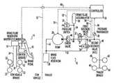
- FIG. 1is a schematic view of a trailer brake system according to a preferred embodiment of the present invention
- FIG. 2is a schematic view showing a variation of the trailer brake system of FIG. 1 wherein the control sensor indicates brake fluid pressure of the tow vehicle;
- FIG. 3is a schematic view showing another variation of the trailer brake system of FIG. 1 wherein the control sensor indicates deceleration of the tow vehicle;
- FIG. 4is a schematic view showing yet another variation of the trailer brake system of FIG. 1 wherein the control sensor indicates deceleration of the trailer.
- down or downwardrefers to a downward direction within the plane of the paper in FIGS. 1-3.
- fore or forwardrefers to a direction toward the front of the tow vehicle and trailer, that is, to the left within the plane of the paper in FIGS. 1-3 and aft or rearward refers to a direction toward the rear of the tow vehicle and trailer, that is, to the right within the plane of the paper in FIGS. 1-3.
- FIG. 1schematically shows a trailer brake system 10 according to a preferred embodiment of the present invention. All components to the left of the broken line 12 are preferably carried by the tow vehicle while all components to the right of the broken 12 are preferably carried by the trailer.
- the present inventioncan be utilized with any type of vehicle system having a motorized tow vehicle with at least one brake and a trailer with at least one brake and pulled by the tow vehicle.
- the tow vehiclecan be, for example an automobile, truck, bus, van, recreational vehicle, tractor, or the like while the trailer can be, for example a camper, recreational, boat, moving, storage, or freight trailer, tag axle, or the like.
- the illustrated tow vehicle brake system 14includes a pivotable brake lever or pedal 16 which when depressed actuates a piston in a master cylinder 18 via a mechanical linkage 20 or alternatively via an electrical wire.
- the actuated master cylinder pistondelivers hydraulic brake fluid to tow vehicle brakes 22 via brake fluid conduits 24 .
- each of the tow vehicle brakes 22can include a hydraulic wheel cylinder operable by fluid force delivered thereto by the brake fluid conduits, brake shoes or the like operable by the wheel cylinder to brake rotation of a wheel, and a spring member operable to release the brake shoes whenever fluid pressure is reduced.
- This illustrated tow vehicle brake system 14is of course standard but it is noted that other suitable tow vehicle brake systems known to those skilled in the art such as, for example, hydraulic drum brakes or disc brakes can be utilized within the scope of the present invention.
- the trailer brake system 10includes a hydraulic brake fluid circuit and a electrical control circuit.
- the brake fluid circuitincludes a brake or hydraulic fluid reservoir 26 , a brake or hydraulic fluid pump 28 , a brake or hydraulic fluid accumulator 30 , first and second solenoid valves 32 , 34 , a pressure sensor or switch 36 , a feedback sensor or pressure transducer 38 , and trailer brakes 40 .
- a first brake fluid conduit 42connects an inlet port of the pump 28 to the fluid reservoir 26 so that a supply of brake fluid is available to the pump 28 .
- a second brake fluid conduit 44connects an outlet port of the pump 28 with an inlet of the first solenoid valve 32 .
- the first solenoid valve 32is preferably a normally closed (N.C.) valve, that is, a valve that is biased to a closed condition and actuatable to an open condition.
- the accumulator 30is located between the pump 28 and the first solenoid valve 32 .
- the accumulator 30can be of any suitable type such as, for example, a gas or spring accumulator.
- a one-way check valve 46is preferably provided between the accumulator 30 and the outlet port of the pump 28 .
- a third brake fluid conduit 48connects an outlet of the first solenoid valve 32 with the trailer brakes 40 . It is noted that the first solenoid valve 32 is directly connected to the trailer brakes without the use of a hydraulic actuator, master cylinder or the like therebetween.
- a fourth brake fluid conduit 50connects the trailer brakes 40 , via the third fluid conduit 48 in the illustrated embodiment, to an inlet of the second solenoid valve 34 .
- the second solenoid valve 34is preferably a normally open (N.O.) valve, that is, a valve that is biased to an open condition and actuatable to a closed condition.
- a fifth brake fluid conduit 52connects an outlet of the second solenoid valve 32 to the brake fluid reservoir 26 .
- the pressure switch 36is positioned to detect fluid pressure in the accumulator 30 , that is, fluid pressure in the circuit between the pump 28 and the first solenoid valve 32 .
- the pressure switch 36is connected to an accumulator conduit 54 which connects the accumulator 30 to the second brake fluid conduit 44 .
- the pressure transducer 38is positioned to detect fluid pressure at the trailer brakes 40 , that is, fluid pressure in the circuit between the first solenoid valve 32 and the trailer brakes 40 .
- the pressure transducer 38is in communication with the third brake fluid conduit 48 . It is noted that other suitable types of feedback sensors 38 known to those skilled in the art which provide a signal which indicate the braking force applied to the trailer brakes can be utilized within the scope of the present invention.
- each of the trailer brakes 40can include a hydraulic wheel cylinder operable by fluid force delivered thereto by the third brake fluid conduit, brake shoes or the like operable by the wheel cylinder to brake rotation of a wheel, and a spring member operable to release the brake shoes whenever fluid pressure is reduced. It is noted that other suitable trailer brakes known to those skilled in the art such as, for example, hydraulic drum or disc brakes can alternatively be utilized within the scope of the present invention.
- the illustrated electrical control circuitincludes a control sensor or switch 56 and a central processing unit or controller 58 .
- the control sensor 56is adapted to provide a signal which indicates that the tow vehicle braking system 14 has been actuated and is preferably adapted to provide a signal which is representative of the degree to which the tow vehicle braking system 14 has been actuated. As shown in FIG. 1, the control sensor 56 can be carried by the tow vehicle and of the type positioned at or near the brake pedal 16 to sense or detect physical movement of the brake pedal 16 .
- tow vehicle brake systemis a “brake-by-wire” system, that is, a system having a sensor which detects movement the brake pedal and sends electrical signals to an electric actuator located at the brake master cylinder to apply a brake force because such a sensor is already present as part of the tow vehicle brake system 14 .
- brake-by-wirea system having a sensor which detects movement the brake pedal and sends electrical signals to an electric actuator located at the brake master cylinder to apply a brake force because such a sensor is already present as part of the tow vehicle brake system 14 .
- suitable control sensors 56known to those skilled in the art which provide a signal which indicates that the tow vehicle braking system 14 has been actuated can be utilized within the scope of the present invention.
- control sensor 56can also be carried by the tow vehicle and of a type adapted to sense brake fluid pressure delivered to the tow vehicle brakes 22 .
- control sensor 56can be a pressure transducer connected to the master cylinder 18 .
- the pressure transducercan sense brake fluid pressure in the master cylinder, and thus how aggressive the tow vehicle braking, and provide a proportional signal to the controller 58 .
- the control sensor 56can also be carried by the tow vehicle and of a type adapted to sense deceleration.
- the control censorcan be an accelerometer carried by the tow vehicle.
- the accelerometercan sense how aggressive the tow vehicle braking and provide a proportional voltage which can be integrated into the controller 58 .
- a gain controlis provided so that the operator can adjust system gain according to the load or weight carried by the trailer. For example, if the trailer is fully loaded, the system gain is set to match but if the trailer load is lighter the system gain is reduced or toned down. The vehicle operator can manually adjust the gain control as the trailer load changes.
- the control sensor 56can alternatively be carried by the trailer.
- the control sensor 56is of a type which works independent of the tow vehicle to provide a signal which indicates that the tow vehicle braking system 14 has been actuated.
- the control sensorcan be an accelerometer carried by the trailer which indicates deceleration of the trailer.
- the accelerometeris preferably provided with a gain control as discussed above which can be carried by the tow vehicle or the trailer.
- the control sensor 56can advantageously be incorporated within the controller 58 .
- An additional advantage the control sensor 56 being carried by the traileris that no hard connections, hydraulic or electric, are required between the tow vehicle and the trailer.
- the illustrated control sensor 56is in communication with the controller 58 by a suitable hard wire or wireless connection 60 .
- the controller 58is preferably provided with suitable memory means and processing means.
- the controller 58can be connected to a suitable power source, provided with a suitable power source, or both.
- the controller 58is in communication with the pressure switch 36 and the pressure transducer 38 via suitable connections 62 , 64 to receive signals representative of pressures at the accumulator 30 and the trailer brakes 40 respectively.
- the controller 58is connected to the first and second solenoid valves 32 , 34 via suitable connections 66 , 68 to selectively open and close the solenoid valves 32 , 34 respectively.
- the controller 58is preferably connected to the pump 28 via a suitable connection 70 to selectively operate the pump 28 .
- the controller 58 or pressure switch 36selectively operates the pump 28 to charge the accumulator 30 with brake fluid at a predetermined pressure.
- the brake fluid in the accumulator 30is held at this predetermined pressure in a stand-by state.
- the control sensor 56sends a signal to the controller 58 .
- the controller 58receives this signal, the controller 58 initiates operation of the pump 28 , closes the second solenoid valve 34 , and opens the first solenoid valve 32 to quickly bring the trailer brakes 40 to a pressure set point desired by the controller 58 .
- the accumulator 30minimizes pressure rise time by quickly supplying pressurized brake fluid to the trailer brakes 40 . It is noted that the accumulator 30 can alternatively be eliminated or supplemented by the controller 58 initially operating a variable-speed motor of the pump at a higher speed to reduce the pressure rise time.
- the first and second solenoid valves 32 , 34are selectively closed and opened by the controller 58 to increase or dump pressure as necessary to maintain fluid pressure at the trailer brakes 40 at the desired pressure set point.
- the pressure set pointcan be: (1) varied or changed to match or follow in a related manner the tow vehicle brake pressure or force as the signal from the control sensor 56 indicates the magnitude of the actuation of the tow vehicle brakes 22 ; (2) a predetermined pressure, particularly when the signal from the control sensor 56 indicates actuation of the tow vehicle brakes 22 but not the magnitude of the actuation; or (3) a combination of the two, that is, a predetermined pressure at times and matched to the tow vehicle brake pressure or force at other times such as, for example, a predetermined pressure set point at low actuations and a variable pressure set point at high actuations.
- the control sensor 56sends a signal to the controller 58 and the controller 58 opens the second solenoid valve 34 and closes the first solenoid valve 32 so that pressure is dumped by returning brake fluid to the reservoir 26 through the second solenoid valve 34 .
- the pump 28continues to operate until the brake fluid in the accumulator 30 reaches the predetermined pressure.
- the pressure switch 36indicates that the brake fluid in the accumulator 30 has reached the predetermined pressure, the pump 28 is shut off.
- the trailer brake system 10repeats the above described operations whenever the tow vehicle brake system 14 is actuated.
- the present inventionprovides an improved hydraulic brake system 10 for a trailer which eliminates both the need for hydraulic brake fluid connections and/or electrical connections between the tow vehicle and trailer and the need for hydraulic actuators and/or master cylinders in the trailer brake system.
Landscapes
- Engineering & Computer Science (AREA)
- Transportation (AREA)
- Mechanical Engineering (AREA)
- Physics & Mathematics (AREA)
- Fluid Mechanics (AREA)
- Regulating Braking Force (AREA)
Abstract
Description
Claims (23)
Priority Applications (1)
| Application Number | Priority Date | Filing Date | Title |
|---|---|---|---|
| US09/955,450US6666527B2 (en) | 2001-06-04 | 2001-09-18 | Electro-hydraulic brake actuating device for a trailer |
Applications Claiming Priority (2)
| Application Number | Priority Date | Filing Date | Title |
|---|---|---|---|
| US29568601P | 2001-06-04 | 2001-06-04 | |
| US09/955,450US6666527B2 (en) | 2001-06-04 | 2001-09-18 | Electro-hydraulic brake actuating device for a trailer |
Publications (2)
| Publication Number | Publication Date |
|---|---|
| US20020180257A1 US20020180257A1 (en) | 2002-12-05 |
| US6666527B2true US6666527B2 (en) | 2003-12-23 |
Family
ID=26969261
Family Applications (1)
| Application Number | Title | Priority Date | Filing Date |
|---|---|---|---|
| US09/955,450Expired - Fee RelatedUS6666527B2 (en) | 2001-06-04 | 2001-09-18 | Electro-hydraulic brake actuating device for a trailer |
Country Status (1)
| Country | Link |
|---|---|
| US (1) | US6666527B2 (en) |
Cited By (21)
| Publication number | Priority date | Publication date | Assignee | Title |
|---|---|---|---|---|
| US6845851B1 (en)* | 2004-01-21 | 2005-01-25 | Automatic Equipment Manufacturing Co. | Braking control system for a vehicle being towed by another vehicle |
| US20050093366A1 (en)* | 2003-10-31 | 2005-05-05 | Jerry A. Edwards | Brake monitoring system |
| US20060049686A1 (en)* | 2004-09-08 | 2006-03-09 | Bess Charles G | Trailer brake system and method |
| US20060071549A1 (en)* | 2004-09-24 | 2006-04-06 | Ronald Chesnut | Electronic controlled vacuum powered brake system for towed trailers |
| US20060158025A1 (en)* | 2005-01-19 | 2006-07-20 | Sauer-Danfoss Aps | Brake valve arrangement |
| US20060175896A1 (en)* | 2005-02-04 | 2006-08-10 | Isaacson Eugene E | Electric hydraulic disc trailer brake |
| US20070024107A1 (en)* | 2005-07-01 | 2007-02-01 | Ford Motor Company | Velocity sensitive passenger vehicle trailer brake controller |
| CN101304909B (en)* | 2005-11-11 | 2012-07-04 | 郑普文 | Brake control system for vehicle and control method thereof |
| US20150344011A1 (en)* | 2012-12-21 | 2015-12-03 | Cnh America Llc | A control apparatus for controlling a brake of a unit hauled by a vehicle |
| US9758138B2 (en) | 2004-10-08 | 2017-09-12 | Horizon Global Americas Inc. | Brake control unit |
| US10040437B2 (en) | 2004-10-08 | 2018-08-07 | Horizon Global Americas Inc. | Brake control unit |
| US10363910B2 (en) | 2016-12-07 | 2019-07-30 | Horizon Global Americas Inc. | Automated gain and boost for a brake controller |
| US10670479B2 (en) | 2018-02-27 | 2020-06-02 | Methode Electronics, Inc. | Towing systems and methods using magnetic field sensing |
| US10696109B2 (en) | 2017-03-22 | 2020-06-30 | Methode Electronics Malta Ltd. | Magnetolastic based sensor assembly |
| US10946841B2 (en) | 2016-09-16 | 2021-03-16 | Horizon Global Americas Inc. | Driver and diagnostic system for a brake controller |
| US11014417B2 (en) | 2018-02-27 | 2021-05-25 | Methode Electronics, Inc. | Towing systems and methods using magnetic field sensing |
| US11084342B2 (en) | 2018-02-27 | 2021-08-10 | Methode Electronics, Inc. | Towing systems and methods using magnetic field sensing |
| US11135882B2 (en) | 2018-02-27 | 2021-10-05 | Methode Electronics, Inc. | Towing systems and methods using magnetic field sensing |
| US11221262B2 (en) | 2018-02-27 | 2022-01-11 | Methode Electronics, Inc. | Towing systems and methods using magnetic field sensing |
| US11279334B2 (en)* | 2017-12-29 | 2022-03-22 | Agco International Gmbh | Load-dependent trailer brake system and method of controlling such |
| US11491832B2 (en) | 2018-02-27 | 2022-11-08 | Methode Electronics, Inc. | Towing systems and methods using magnetic field sensing |
Families Citing this family (15)
| Publication number | Priority date | Publication date | Assignee | Title |
|---|---|---|---|---|
| US7452038B2 (en)* | 2006-01-20 | 2008-11-18 | Towhaul Corporation | System and method for remotely releasing a parking brake on a disabled vehicle |
| FR2897581B1 (en)* | 2006-02-22 | 2008-05-16 | Poclain Hydraulics Ind Soc Par | DEVICE FOR CONTROLLING THE HYDRAULIC BRAKE OF A TRAILER ATTACHED TO A TRACTOR |
| NL2000521C1 (en) | 2007-03-05 | 2008-09-08 | Bart Veldhuizen B V | Binary G-sensor controlled braking system for a trailer. |
| US7517026B1 (en)* | 2007-12-05 | 2009-04-14 | Deere & Company | Control circuit for trailer brakes in a by-wire brake system |
| US9150201B2 (en)* | 2008-11-25 | 2015-10-06 | Cequent Performance Products, Inc. | Universal trailer mounted proportional brake controller |
| KR101673046B1 (en)* | 2009-08-24 | 2016-11-16 | 켈시-헤이즈 컴파니 | Attenuator for a vehicle braking system |
| PL216956B1 (en)* | 2010-04-14 | 2014-05-30 | Przemysłowy Inst Masz Rolniczych | Electro-pneumatic system for controlling the pneumatic-hydraulic operation system and hydraulic brakes, especially light and medium-size trailers and semitrailers |
| GB2497981B (en)* | 2011-12-23 | 2013-11-13 | Charles Linfield Davies | Generating travel time data |
| US8905177B2 (en)* | 2012-03-27 | 2014-12-09 | Vitaly Grossman | Wheeled platform powered by a cargo tracked vehicle and method of propulsion control thereof |
| US20150353063A1 (en)* | 2014-06-09 | 2015-12-10 | Continental Automotive Systems, Inc. | Trailer brake system having trailer gain optimization |
| US9663079B2 (en)* | 2014-12-02 | 2017-05-30 | Toyota Motor Engineering & Manufacturing North America, Inc. | Systems for controlling trailer brake output circuits and systems for monitoring manual trailer brake activation slider circuits |
| US10173652B2 (en)* | 2016-07-28 | 2019-01-08 | Deere & Company | Hydraulic trailer brake circuit for adjustable gain and improved stability |
| US10480163B2 (en)* | 2017-01-27 | 2019-11-19 | Ford Global Technologies, Llc | Vehicle-to-trailer transfer of harvested and purified water |
| FI127269B (en)* | 2017-03-07 | 2018-02-28 | Ak Usatrucks Oy | braking System |
| US12005877B2 (en)* | 2020-05-06 | 2024-06-11 | TRP International, LLC | Electric over hydraulic brake system with magnetic sensor |
Citations (23)
| Publication number | Priority date | Publication date | Assignee | Title |
|---|---|---|---|---|
| US2127890A (en) | 1937-11-17 | 1938-08-23 | Ellery M Sills | Automatic safety brake device |
| US2142514A (en) | 1937-07-30 | 1939-01-03 | Elmon C Gillette | Vacuum brake booster |
| US2248435A (en) | 1938-06-14 | 1941-07-08 | Teves Kg Alfred | Compressed air actuated hydraulic brake |
| US2940561A (en) | 1956-05-28 | 1960-06-14 | Kelsey Hayes Co | Brake control system |
| US2941844A (en) | 1958-04-07 | 1960-06-21 | Kelsey Hayes Co | Tractor-trailer brake system |
| US3171694A (en) | 1961-10-03 | 1965-03-02 | Temptron Corp | Electric-hydraulic tow brake unit |
| US3695731A (en) | 1968-02-01 | 1972-10-03 | Michael John England | Vehicle braking system |
| US3756666A (en) | 1971-06-03 | 1973-09-04 | Teldix Gmbh | Hydraulic brake servo arrangement |
| US3768870A (en) | 1972-03-15 | 1973-10-30 | D Howard | Electrically actuated trailer brake control system |
| US3834767A (en) | 1973-03-26 | 1974-09-10 | D Bullinger | Trailer auxiliary hydraulic brake system |
| US3880472A (en) | 1973-11-19 | 1975-04-29 | Bendix Corp | Hydraulic braking system for a trailer |
| US3951464A (en) | 1974-08-30 | 1976-04-20 | Donahue James C | Truck-trailer brake system with independent control of trailer brakes |
| US3985395A (en) | 1975-07-23 | 1976-10-12 | Watanabe S Frank | Remote control brake system for trailers |
| US3995911A (en) | 1975-09-29 | 1976-12-07 | The Bendix Corporation | Tow vehicle-trailer braking system |
| US4054425A (en) | 1971-01-22 | 1977-10-18 | Sherman William F | Process of making a grinding wheel assembly |
| US4099790A (en) | 1976-11-18 | 1978-07-11 | Hipps Larry W | Electro-hydraulic brake actuating system |
| US4280737A (en) | 1979-10-26 | 1981-07-28 | Hipps Larry W | Pressure controlled electro-hydraulic brake system |
| US4402553A (en) | 1979-10-26 | 1983-09-06 | Hipps Larry W | Pressure controlled electro-hydraulic brake system |
| US4787205A (en) | 1985-02-14 | 1988-11-29 | Fontaine William G | Vehicle brake system |
| US5213396A (en) | 1990-12-06 | 1993-05-25 | Avery Larry L | Towed vehicle brake activation method and apparatus |
| US5382085A (en) | 1990-12-17 | 1995-01-17 | Zbinden; Otto | Electrohydraulic or electropneumatic braking control device for axles of trailers with mechanical brakes, and safety valve |
| US5626402A (en) | 1994-06-21 | 1997-05-06 | Gordon Wilbur Chiles | Apparatus for simultaneously applying brakes of a trailer when brakes of a towing vehicle are applied |
| US5806937A (en) | 1996-05-28 | 1998-09-15 | Trailer Component Innovations, Llc. | Trailer braking system |
- 2001
- 2001-09-18USUS09/955,450patent/US6666527B2/ennot_activeExpired - Fee Related
Patent Citations (23)
| Publication number | Priority date | Publication date | Assignee | Title |
|---|---|---|---|---|
| US2142514A (en) | 1937-07-30 | 1939-01-03 | Elmon C Gillette | Vacuum brake booster |
| US2127890A (en) | 1937-11-17 | 1938-08-23 | Ellery M Sills | Automatic safety brake device |
| US2248435A (en) | 1938-06-14 | 1941-07-08 | Teves Kg Alfred | Compressed air actuated hydraulic brake |
| US2940561A (en) | 1956-05-28 | 1960-06-14 | Kelsey Hayes Co | Brake control system |
| US2941844A (en) | 1958-04-07 | 1960-06-21 | Kelsey Hayes Co | Tractor-trailer brake system |
| US3171694A (en) | 1961-10-03 | 1965-03-02 | Temptron Corp | Electric-hydraulic tow brake unit |
| US3695731A (en) | 1968-02-01 | 1972-10-03 | Michael John England | Vehicle braking system |
| US4054425A (en) | 1971-01-22 | 1977-10-18 | Sherman William F | Process of making a grinding wheel assembly |
| US3756666A (en) | 1971-06-03 | 1973-09-04 | Teldix Gmbh | Hydraulic brake servo arrangement |
| US3768870A (en) | 1972-03-15 | 1973-10-30 | D Howard | Electrically actuated trailer brake control system |
| US3834767A (en) | 1973-03-26 | 1974-09-10 | D Bullinger | Trailer auxiliary hydraulic brake system |
| US3880472A (en) | 1973-11-19 | 1975-04-29 | Bendix Corp | Hydraulic braking system for a trailer |
| US3951464A (en) | 1974-08-30 | 1976-04-20 | Donahue James C | Truck-trailer brake system with independent control of trailer brakes |
| US3985395A (en) | 1975-07-23 | 1976-10-12 | Watanabe S Frank | Remote control brake system for trailers |
| US3995911A (en) | 1975-09-29 | 1976-12-07 | The Bendix Corporation | Tow vehicle-trailer braking system |
| US4099790A (en) | 1976-11-18 | 1978-07-11 | Hipps Larry W | Electro-hydraulic brake actuating system |
| US4280737A (en) | 1979-10-26 | 1981-07-28 | Hipps Larry W | Pressure controlled electro-hydraulic brake system |
| US4402553A (en) | 1979-10-26 | 1983-09-06 | Hipps Larry W | Pressure controlled electro-hydraulic brake system |
| US4787205A (en) | 1985-02-14 | 1988-11-29 | Fontaine William G | Vehicle brake system |
| US5213396A (en) | 1990-12-06 | 1993-05-25 | Avery Larry L | Towed vehicle brake activation method and apparatus |
| US5382085A (en) | 1990-12-17 | 1995-01-17 | Zbinden; Otto | Electrohydraulic or electropneumatic braking control device for axles of trailers with mechanical brakes, and safety valve |
| US5626402A (en) | 1994-06-21 | 1997-05-06 | Gordon Wilbur Chiles | Apparatus for simultaneously applying brakes of a trailer when brakes of a towing vehicle are applied |
| US5806937A (en) | 1996-05-28 | 1998-09-15 | Trailer Component Innovations, Llc. | Trailer braking system |
Cited By (34)
| Publication number | Priority date | Publication date | Assignee | Title |
|---|---|---|---|---|
| US20050093366A1 (en)* | 2003-10-31 | 2005-05-05 | Jerry A. Edwards | Brake monitoring system |
| US6845851B1 (en)* | 2004-01-21 | 2005-01-25 | Automatic Equipment Manufacturing Co. | Braking control system for a vehicle being towed by another vehicle |
| US7114786B2 (en)* | 2004-09-08 | 2006-10-03 | Bess Charles G | Trailer brake system and method |
| US20060049686A1 (en)* | 2004-09-08 | 2006-03-09 | Bess Charles G | Trailer brake system and method |
| US20060071549A1 (en)* | 2004-09-24 | 2006-04-06 | Ronald Chesnut | Electronic controlled vacuum powered brake system for towed trailers |
| US11400903B2 (en) | 2004-10-08 | 2022-08-02 | Horizon Global Americas Inc. | Brake control unit |
| US11738729B2 (en) | 2004-10-08 | 2023-08-29 | Horizon Global Americas Inc. | Brake control unit |
| US12162461B2 (en) | 2004-10-08 | 2024-12-10 | Horizon Global Americas Inc. | Brake control unit |
| US10688977B2 (en) | 2004-10-08 | 2020-06-23 | Horizon Global Americas Inc. | Brake control unit |
| US9758138B2 (en) | 2004-10-08 | 2017-09-12 | Horizon Global Americas Inc. | Brake control unit |
| US10040437B2 (en) | 2004-10-08 | 2018-08-07 | Horizon Global Americas Inc. | Brake control unit |
| US20060158025A1 (en)* | 2005-01-19 | 2006-07-20 | Sauer-Danfoss Aps | Brake valve arrangement |
| US7703861B2 (en) | 2005-01-19 | 2010-04-27 | Sauer-Danfoss Aps | Brake valve arrangement |
| US20060175896A1 (en)* | 2005-02-04 | 2006-08-10 | Isaacson Eugene E | Electric hydraulic disc trailer brake |
| US8757735B2 (en) | 2005-07-01 | 2014-06-24 | Ford Global Technologies | Velocity sensitive passenger vehicle trailer brake controller |
| US8511759B2 (en)* | 2005-07-01 | 2013-08-20 | Ford Global Technologies | Velocity sensitive passenger vehicle trailer brake controller |
| US20070024107A1 (en)* | 2005-07-01 | 2007-02-01 | Ford Motor Company | Velocity sensitive passenger vehicle trailer brake controller |
| CN101304909B (en)* | 2005-11-11 | 2012-07-04 | 郑普文 | Brake control system for vehicle and control method thereof |
| US9561784B2 (en)* | 2012-12-21 | 2017-02-07 | Cnh Industrial America Llc | Control apparatus for controlling a brake of a unit hauled by a vehicle |
| US20150344011A1 (en)* | 2012-12-21 | 2015-12-03 | Cnh America Llc | A control apparatus for controlling a brake of a unit hauled by a vehicle |
| US12384336B2 (en) | 2016-09-16 | 2025-08-12 | Horizon Global Americas Inc. | Driver and diagnostic system for a brake controller |
| US10946841B2 (en) | 2016-09-16 | 2021-03-16 | Horizon Global Americas Inc. | Driver and diagnostic system for a brake controller |
| US11731594B2 (en) | 2016-09-16 | 2023-08-22 | Horizon Global Americas Inc. | Driver and diagnostic system for a brake controller |
| US10363910B2 (en) | 2016-12-07 | 2019-07-30 | Horizon Global Americas Inc. | Automated gain and boost for a brake controller |
| US11440516B2 (en) | 2016-12-07 | 2022-09-13 | Horizon Global Americas Inc. | Automated gain and boost for a brake controller |
| US10940726B2 (en) | 2017-03-22 | 2021-03-09 | Methode Electronics Malta Ltd. | Magnetoelastic based sensor assembly |
| US10696109B2 (en) | 2017-03-22 | 2020-06-30 | Methode Electronics Malta Ltd. | Magnetolastic based sensor assembly |
| US11279334B2 (en)* | 2017-12-29 | 2022-03-22 | Agco International Gmbh | Load-dependent trailer brake system and method of controlling such |
| US11135882B2 (en) | 2018-02-27 | 2021-10-05 | Methode Electronics, Inc. | Towing systems and methods using magnetic field sensing |
| US11221262B2 (en) | 2018-02-27 | 2022-01-11 | Methode Electronics, Inc. | Towing systems and methods using magnetic field sensing |
| US11084342B2 (en) | 2018-02-27 | 2021-08-10 | Methode Electronics, Inc. | Towing systems and methods using magnetic field sensing |
| US11491832B2 (en) | 2018-02-27 | 2022-11-08 | Methode Electronics, Inc. | Towing systems and methods using magnetic field sensing |
| US11014417B2 (en) | 2018-02-27 | 2021-05-25 | Methode Electronics, Inc. | Towing systems and methods using magnetic field sensing |
| US10670479B2 (en) | 2018-02-27 | 2020-06-02 | Methode Electronics, Inc. | Towing systems and methods using magnetic field sensing |
Also Published As
| Publication number | Publication date |
|---|---|
| US20020180257A1 (en) | 2002-12-05 |
Similar Documents
| Publication | Publication Date | Title |
|---|---|---|
| US6666527B2 (en) | Electro-hydraulic brake actuating device for a trailer | |
| US8500216B2 (en) | Vehicle parking brake and operating method | |
| US11052892B2 (en) | Electronically controllable pneumatic brake system in a utility vehicle and method for electronically controlling a pneumatic brake system | |
| US8651588B2 (en) | Electro-pneumatic brake control device | |
| US8152243B2 (en) | Electrically controlled brake system | |
| US10654458B2 (en) | Electronic brake system for a compressed air braking system of a utility vehicle | |
| US9327694B2 (en) | Brake module for a hydraulically braked towing vehicle coupleable to a pneumatically braked trailer vehicle | |
| US8197014B2 (en) | Brake system for a vehicle | |
| JPH09506314A (en) | Electro-pneumatic braking device used in automobiles | |
| US20150061362A1 (en) | Brake control apparatus | |
| CN110785330B (en) | Vehicle brake system | |
| US5938297A (en) | Method and device for brake application | |
| US11970146B2 (en) | Secondary brake system of a vehicle, and method for controlling it | |
| JP2004522639A (en) | Electro-hydraulic brake system for automobile | |
| JPH11509807A (en) | Brake system for trailer vehicle and valve used therein | |
| US20020195870A1 (en) | Trailer braking system | |
| US20240092329A1 (en) | Trailer Brake Control System | |
| US6345871B1 (en) | Pedal travel limitation in electro-hydraulic (EHB) braking systems | |
| CN114906112B (en) | Pneumatic brake system for a vehicle axle | |
| CN117396383A (en) | Electropneumatic equipment for vehicles with autonomous braking circuits supplied preventively with backup pressure | |
| US20060017317A1 (en) | Selective actuation of secondary circuit of dual brake valve | |
| WO2023069435A1 (en) | Trailer braking through trailer supply line | |
| US6264291B1 (en) | Spring brake actuator with integral biased double check valve for anti-compounding and roll-back protection | |
| US20030019694A1 (en) | Dry interface corner vehicle braking system | |
| JP2010502505A (en) | Automotive braking system |
Legal Events
| Date | Code | Title | Description |
|---|---|---|---|
| AS | Assignment | Owner name:ATWOOD MOBILE PRODUCTS, INC., ILLINOIS Free format text:ASSIGNMENT OF ASSIGNORS INTEREST;ASSIGNORS:GILL, GEORGE PATRICK;SWANSON, DAVID LEONARD;REEL/FRAME:012183/0472 Effective date:20010912 | |
| AS | Assignment | Owner name:BANK OF AMERICA, N.A., AS COLLATERAL AGENT,WISCONS Free format text:SECURITY AGREEMENT;ASSIGNOR:DURA GLOBAL TECHNOLOGIES, INC.;REEL/FRAME:016026/0033 Effective date:20050503 Owner name:BANK OF AMERICA, N.A., AS COLLATERAL AGENT, WISCON Free format text:SECURITY AGREEMENT;ASSIGNOR:DURA GLOBAL TECHNOLOGIES, INC.;REEL/FRAME:016026/0033 Effective date:20050503 | |
| AS | Assignment | Owner name:WILMINGTON TRUST COMPANY, AS COLLATERAL AGENT,DELA Free format text:SECURITY AGREEMENT;ASSIGNOR:DURA GLOBAL TECHNOLOGIES, INC.;REEL/FRAME:016377/0466 Effective date:20050628 Owner name:WILMINGTON TRUST COMPANY, AS COLLATERAL AGENT, DEL Free format text:SECURITY AGREEMENT;ASSIGNOR:DURA GLOBAL TECHNOLOGIES, INC.;REEL/FRAME:016377/0466 Effective date:20050628 | |
| REMI | Maintenance fee reminder mailed | ||
| AS | Assignment | Owner name:MERRILL LYNCH CAPITAL, A DIVISION OF MERRILL LYNCH Free format text:SECURITY AGREEMENT;ASSIGNOR:ATWOOD MOBILE PRODUCTS LLC;REEL/FRAME:019754/0247 Effective date:20070827 | |
| LAPS | Lapse for failure to pay maintenance fees | ||
| STCH | Information on status: patent discontinuation | Free format text:PATENT EXPIRED DUE TO NONPAYMENT OF MAINTENANCE FEES UNDER 37 CFR 1.362 | |
| FP | Expired due to failure to pay maintenance fee | Effective date:20071223 | |
| AS | Assignment | Owner name:ATWOOD MOBILE PRODUCTS LLC, INDIANA Free format text:ASSIGNMENT OF ASSIGNORS INTEREST;ASSIGNOR:ATWOOD MOBILE PRODUCTS, INC.;REEL/FRAME:021127/0676 Effective date:20070827 | |
| AS | Assignment | Owner name:ATWOOD MOBILE PRODUCTS LLC, INDIANA Free format text:RELEASE BY SECURED PARTY;ASSIGNOR:GE BUSINESS FINANCIAL SERVICES, INC. (F/K/A MERRILL LYNCH CAPITAL), A DIVISION OF MERRILL LYNCH FINANCIAL SERVICES INC.), AS ADMINISTRATIVE AGENT;REEL/FRAME:028582/0478 Effective date:20120718 |