US6665714B1 - Method and apparatus for determining an identity of a network device - Google Patents
Method and apparatus for determining an identity of a network deviceDownload PDFInfo
- Publication number
- US6665714B1 US6665714B1US09/345,254US34525499AUS6665714B1US 6665714 B1US6665714 B1US 6665714B1US 34525499 AUS34525499 AUS 34525499AUS 6665714 B1US6665714 B1US 6665714B1
- Authority
- US
- United States
- Prior art keywords
- network device
- network
- storage system
- storage
- host
- Prior art date
- Legal status (The legal status is an assumption and is not a legal conclusion. Google has not performed a legal analysis and makes no representation as to the accuracy of the status listed.)
- Expired - Lifetime
Links
Images


Classifications
- H—ELECTRICITY
- H04—ELECTRIC COMMUNICATION TECHNIQUE
- H04L—TRANSMISSION OF DIGITAL INFORMATION, e.g. TELEGRAPHIC COMMUNICATION
- H04L63/00—Network architectures or network communication protocols for network security
- H04L63/04—Network architectures or network communication protocols for network security for providing a confidential data exchange among entities communicating through data packet networks
- H04L63/0428—Network architectures or network communication protocols for network security for providing a confidential data exchange among entities communicating through data packet networks wherein the data content is protected, e.g. by encrypting or encapsulating the payload
- H—ELECTRICITY
- H04—ELECTRIC COMMUNICATION TECHNIQUE
- H04L—TRANSMISSION OF DIGITAL INFORMATION, e.g. TELEGRAPHIC COMMUNICATION
- H04L67/00—Network arrangements or protocols for supporting network services or applications
- H04L67/50—Network services
- H04L67/75—Indicating network or usage conditions on the user display
- H—ELECTRICITY
- H04—ELECTRIC COMMUNICATION TECHNIQUE
- H04L—TRANSMISSION OF DIGITAL INFORMATION, e.g. TELEGRAPHIC COMMUNICATION
- H04L9/00—Cryptographic mechanisms or cryptographic arrangements for secret or secure communications; Network security protocols
- H04L9/40—Network security protocols
- G—PHYSICS
- G06—COMPUTING OR CALCULATING; COUNTING
- G06F—ELECTRIC DIGITAL DATA PROCESSING
- G06F11/00—Error detection; Error correction; Monitoring
- G06F11/07—Responding to the occurrence of a fault, e.g. fault tolerance
- G06F11/16—Error detection or correction of the data by redundancy in hardware
- G06F11/20—Error detection or correction of the data by redundancy in hardware using active fault-masking, e.g. by switching out faulty elements or by switching in spare elements
- G06F11/2002—Error detection or correction of the data by redundancy in hardware using active fault-masking, e.g. by switching out faulty elements or by switching in spare elements where interconnections or communication control functionality are redundant
- G06F11/2007—Error detection or correction of the data by redundancy in hardware using active fault-masking, e.g. by switching out faulty elements or by switching in spare elements where interconnections or communication control functionality are redundant using redundant communication media
- G06F11/201—Error detection or correction of the data by redundancy in hardware using active fault-masking, e.g. by switching out faulty elements or by switching in spare elements where interconnections or communication control functionality are redundant using redundant communication media between storage system components
Definitions
- This inventionrelates generally to the field of information storage systems and more particularly to a method and apparatus for managing storage in a storage system.
- Computer systemsgenerally include one or more host processors and a storage system for storing data accessed by the host processor.
- the storage systemmay include one or more storage devices (e.g., disk drives) to service the storage needs of the host processor.
- Disk drivesmay include one or more disks of a recording media, such as a magnetic recording medium or an optical recording medium.
- a busprovides an interconnect between the host processor and the storage system.
- the busoperates according to a protocol, such as the Small Component System Interconnect (SCSI) protocol, which dictates a format of packets transferred between the host processor and the storage system.
- SCSISmall Component System Interconnect
- requests and responsesare forwarded to and from the storage system over the bus.
- Fibre Channelis an example of a network that can be used to form such a configuration.
- Fibre Channelis a network standard that allows multiple initiators to communicate with multiple targets over the network, where the initiator and target may be any device coupled to the network.
- multiple hostsare able to share access to a single storage system.
- One problem with coupling multiple hosts to a shared storage systemis the management of data access at the storage system. Because multiple hosts have access to a common storage system, each host may physically be able to access information that may be proprietary to the other host processors.
- a data management method for managing access to a storage system by at least two devices coupled to the storage systemincludes a step of selectively servicing, at the storage system, a request from one of the at least two devices for access to a portion of data stored at the storage system responsive to configuration data indicating that the one of at least two devices is authorized to access the portion of data.
- a computer readable mediumincludes a first data structure to manage accesses by a plurality of devices to volumes of data at a storage system, the first data structure comprising a plurality of records corresponding to the plurality of devices, each record of the plurality of records corresponding to one of the plurality of devices and including configuration information identifying which of the volumes of the storage system the one of the plurality of devices is authorized to access.
- a storage systemincludes at least one storage device apportioned into a plurality of volumes, a configuration table to store configuration data identifying which of a plurality of devices coupled to the storage system are authorized to access each of the plurality of volumes, and a filter, responsive to the configuration data, to selectively forward to the at least one storage device requests for access to the plurality of volumes received from the plurality of devices.
- a computer readable mediumis provided.
- the computer readable mediumis encoded with a program for execution on a computer system that includes a plurality of host processors that are coupled to a storage system over a network.
- the programwhen executed on the computer system, performs a method including a step of displaying a first representation of each of the plurality of host processors that is logged into the storage system.
- a methodfor use in a computer system having a plurality of host processors that are coupled to a storage system over a network.
- the methodincludes a step of displaying, on a display in the computer system, a first representation of each of the plurality of host processors that is logged into the storage system over the network.
- a computer readable mediumis provided.
- the computer readable mediumis encoded with a program that, when executed on a computer system including a plurality of host processors that are coupled to a storage system over a network, performs a method including steps of displaying a graphical representation of a portion of data that is stored on the storage system, displaying access privileges to the portion of data stored on the storage system, and modifying the access privileges to the portion of data by one of the plurality of host processors in response to a graphical selection of the graphical representation of the portion of data.
- a method of managing access to data stored on a storage system from a plurality of host processors that are coupled to the storage system over a networkincludes steps of displaying a graphical representation of a portion of the data stored on the storage system, displaying access privileges to the portion of the data, and modifying the access privileges to the portion of the data by one of the plurality of host processors in response to a graphical selection of the graphical representation of the portion of the data.
- a computer readable mediumis provided.
- the computer readable mediumis encoded with a program that, when executed on a computer system including a plurality of host processors that are coupled to a storage system over a network, performs a method including steps of displaying a graphical representation of one of the plurality of host processors, displaying access privileges to a portion of data stored on the storage system, and modifying the access privileges to the portion of data by the one of the plurality of host processors in response to a graphical selection of the graphical representation of the one of the plurality of host processors.
- a method of managing access to data stored on a storage system from a plurality of host processors that are coupled to the storage system over a networkincludes steps of displaying a graphical representation of one of the plurality of host processors, displaying access privileges to a portion of the data stored on the storage system, and modifying the access privileges to the portion of the data by the one of the plurality of host processors in response to a graphical selection of the graphical representation of the one of the plurality of host processors.
- a computer readable mediumincludes a data structure to manage access by a plurality of network devices to data stored on a storage system.
- the data structureincludes at least one record identifying each one of the plurality of network devices that is logged into the storage system.
- a storage systemincludes at least one storage device, a memory that is coupled to the at least one storage device, and at least one processor that is coupled to the at least one storage device and the memory.
- the at least one processorstores at least one record in the memory identifying at least one of a plurality of network devices that is logged into the storage system.
- a method of enabling a first network device to determine an identity of the first network deviceis provided.
- the first network deviceis coupled to a second network device by a network.
- the methodincludes steps of sending a communication from the first network device to the second network device over the network, and requesting the second network device to identify, to the first network device, an origin from which the first communication was received.
- a computer readable mediumis provided.
- the computer readable mediumis encoded with a program that, when executed on a first network device that is coupled to a second network device over a network, performs a method including steps of sending a communication from the first network device to the second network device over the network, and requesting the second network device to identify, to the first network device, an origin from which the first communication was received.
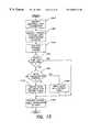
- FIGS. 1A, 1 B and 1 Cillustrate exemplary network configurations in which the data management aspect of the present invention can be employed
- FIG. 2illustrates one embodiment of a packet that can be distributed between devices coupled in the networks of FIGS. 1A, 1 B or 1 C;
- FIG. 3is a block diagram illustrating exemplary components of a host processor and storage system which may be coupled in the networks of FIGS. 1A, 1 B or 1 C, the storage system including an adapter having elements for filtering requests issued by the host processor according to one embodiment of the present invention;
- FIG. 4is a block diagram of one embodiment of a configuration data structure that may be used to store filtering information for use by the storage system of FIG. 3;
- FIG. 5is a block diagram of one embodiment of filtering data that may be used to filter requests at the storage system of FIG. 3;
- FIG. 6is a block diagram illustrating exemplary components of a host processor and storage system that may be coupled in the network of FIGS. 1A, 1 B or 1 C, the storage system including logic for authenticating transactions by the host according to one embodiment of the present invention
- FIG. 7is a flow diagram illustrating one method of distributing encryption keys between a host processor and storage system of FIG. 6, so that the encryption keys can be used to authenticate the identity of the host processor;
- FIGS. 8 a-care a flow diagram illustrating one method of authenticating the identity of a host processor when establishing a connection between the host processor and storage system of FIG. 6 in accordance with one embodiment of the invention
- FIG. 9is a diagram illustrating exemplary components that may be included in an authentication table of the storage system of FIG. 6 and that may be used to authenticate the identity of host processors according to one embodiment of the invention.
- FIG. 10is a flow diagram illustrating one method of performing a checksum of data transferred between an initiator and target in the networks of FIGS. 1A, 1 B and 1 C for validating data transfers in one embodiment of the invention
- FIG. 11is a flow diagram illustrating one method of validating a data transfer between an initiator and target using the checksum of FIG. 10 according to one embodiment of the invention
- FIG. 12is a block diagram of a storage network that includes a storage system with which various aspects of the present invention may be employed;
- FIG. 13is a flow diagram illustrating one method of assigning an identifier to network devices in a storage network according to one embodiment of the present invention
- FIG. 14illustrates a management window for managing network devices and access to data stored on a storage system that can be provided by a graphical user interface according to one embodiment of the present invention
- FIG. 15illustrates one method of graphically representing network devices and portions of data stored on a storage system that can be provided by a graphical user interface
- FIG. 16illustrates one method of graphically representing how data is stored on a storage system that can be provided by a graphical user interface according to one embodiment of the present invention
- FIG. 17illustrates one method of graphically representing varying levels of detail of how network devices are interconnected in a storage network that can be provided by a graphical user interface according to one embodiment of the present invention
- FIG. 18illustrates a management window showing a first step in a configuration process, for configuring access to a storage system from different hosts in a storage network, using a graphical user interface according to one embodiment of the present invention
- FIG. 19illustrates a management window showing a second step in the configuration process of FIG. 18, for configuring access to specific ports on a storage system, using a graphical user interface according to one embodiment of the present invention
- FIG. 20illustrates a management window showing a third step in the configuration process of FIG. 18, for configuring access to a specific port on a storage system from a specific port on a host system, using a graphical user interface according to one embodiment of the present invention
- FIG. 21illustrates a task list that can be displayed by a graphical user interface according to one embodiment of the present invention to confirm configuration of a specific port on a storage system from a specific port on a host system;
- FIG. 22illustrates a management window showing a fourth step in the configuration process of FIG. 18, for configuring access to a specific storage volume on a storage system using a specific port of a storage system and a specific port on a host system, using a graphical user interface according to one embodiment of the present invention.
- the present inventionis directed to a data management method and apparatus for managing accesses by multiple devices (e.g., host processors, file servers and the like) to data at a shared resource (e.g., a shared storage system).
- the shared resourceselectively services requests from the devices for portions of data at the shared resource in response to configuration data associated with each of the portions of data at the resource.
- data at the shared resourceis apportioned into volumes.
- Configuration dataidentifies which volumes of data are available for access by each of the devices coupled to the resource (e.g., over a network).
- the shared resourceincludes a filter that selectively forwards a request for servicing depending upon the identity of the device issuing the request and the configuration data associated with the volume to which access is sought. The filter forwards only those requests for volumes that the device has privileges to access. Requests to volumes for which the device does not have privileges are not serviced.
- Filtering requests at the resourceallows the control of the data management to be centralized in one location, rather than distributed throughout the network. Centralizing the data management control at the storage system removes the need to trust the hosts seeking access to the storage system to only access certain portions of data.
- security protectionmay be added to further secure the data at the resource. Because filtering is performed in response to the identity of the device initiating the request, data security may be compromised if a device falsely represents its identity to gain access to the resource. In addition, data transfers between the device and the resource may be corrupted by other devices coupled (e.g., over a network) to the resource.
- an authentication method and apparatusis provided to verify that the device that is represented as the device issuing the request is truly the device that issued the request. The authentication method may therefore be implemented to overcome security problems associated with a device misrepresenting its identity to obtain data at the resource.
- a validation method and apparatusis provided to ensure that information, transferred between the device and the shared resource is not corrupted (either inadvertently or intentionally) during transit.
- a data management system for managing data at a resourcemay use any or all of these filtering, authentication and validation techniques.
- One exemplary system wherein the data management method and apparatus of the present invention may be employedis in a networked computer system, wherein the devices are host processors or file servers coupled to the network, and the shared resource is a storage system (e.g., a disk device storage system).
- the use of a network, host processor or shared disk deviceis not a limitation of the present invention, and that such a system configuration is described below solely for purposes of illustration.
- one or more hostsmay be coupled to one or more storage systems using a network, with requests and responses being forwarded to and from the storage systems over the network according to the protocol of the network.
- each host and storage systemmay include one or more ports for interfacing the host or storage system to a corresponding one or more networks.
- each storage system in the networkincludes logic for filtering received requests to manage data accesses to the storage system.
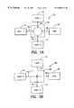
- FIG. 1Aillustrates a network 10 arranged in a loop configuration, where all devices in the network are coupled together in a single loop.
- FIG. 1Athree host processors 12 , 14 and 16 are shown coupled to a storage system 20 by a hub 18 a . Internally, the hub is arranged in a loop configuration. Communication between the devices, over the busses 15 a - 15 d , is performed by passing data packets from one device to the next in the loop.
- FIG. 1Aillustrates a network 10 arranged in a loop configuration, where all devices in the network are coupled together in a single loop.
- three host processors 12 , 14 and 16are shown coupled to a storage system 20 by a hub 18 a . Internally, the hub is arranged in a loop configuration. Communication between the devices, over the busses 15 a - 15 d , is performed by passing data packets from one device to the next in the loop.
- FIG. 1Aillustrates a network 10 arranged in a loop configuration, where all
- FIG. 1Billustrates a network 30 arranged in a fabric configuration, where all the devices are coupled together by a switch 18 b . Communication between pairs of the devices 12 , 14 , 16 and 20 in the network 30 is controlled by the switch 18 b .
- the data management method of the present inventionmay be employed in networks arranged in the loop or fabric configurations illustrated in FIGS. 1A and 1B, or alternatively in other network or resource sharing configurations.
- the data management aspectmay be employed in the network illustrated in FIG. 1 C.
- FIG. 1Ca host/storage system configuration is shown where the storage system includes two ports, each of which interfaces the storage system to a different network.
- a first port (Port 0 )is coupled to a fabric network 10 and a second port (Port 1 ) is coupled to a loop network 30 .
- the data management aspect of the present inventionconfigures volumes of data at the storage system 20 according to the identity of the host devices coupled to the storage system.
- the configuration data that is used to manage the allocation of volumes to different hostsmay be provided, for example, by a system administrator of the network.
- the system administratortracks the host devices that are coupled to the network and the available volumes at the storage system.
- the system administratorallocates storage system volumes to the host.
- the number of volumes allocated to the hostmay be based on a requested number of volumes, or alternatively may be based on historical data requirements of the host.
- the system administratormay be implemented in software, executing on one of the devices or storage systems in the network, and may include a graphical user interface to enable users to monitor the availability and assignment of volumes to different hosts in the network.
- the present inventionis not limited to any particular implementation of the system administrator.
- the Fibre Channel interconnectis capable of carrying multiple interface command sets. Accordingly, the devices that are coupled together using the Fibre Channel network may communicate using any of a number of higher level protocols including Internet Protocol (IP), Small Component System Interconnect (SCSI) protocol, or any of a number of other protocols, provided that the interfacing devices have knowledge of the type of protocol that is being used on the particular Fibre Channel interconnect. Certain types of devices have historically been designed to communicate using certain protocols. For example, host processor devices have historically communicated with storage systems using the SCSI protocol. Thus, devices coupled using the Fibre Channel network may communicate with each other using the same protocols that have historically been used. As a result, existing interfaces of the devices require little redesign to couple to the Fibre Channel network.
- IPInternet Protocol
- SCSISmall Component System Interconnect
- Tunneling techniquestypically are used to convert packets of any type of protocol into packets that may be propagated on the Fibre Channel network. Using tunneling, one packet, formatted according to a first protocol, is enveloped in a second packet formatted according to the Fibre Channel network protocol. Thus, a SCSI packet may be enveloped in a Fibre Channel packet by a host processor or storage system for transmission on a Fibre Channel network.
- a packet formatted according to a SCSI protocol and enveloped in a Fibre Channel packetis illustrated in FIG. 2 .
- a Fibre Channel packet 50includes a header portion 55 and a payload portion 60 .
- the header portion 55includes a source ID field 52 , a destination ID field 53 and a length field 54 .
- the source ID field 52identifies a device in the network that initiated the transmission of the packet 50 .
- the destination ID field 53identifies a target device for receiving the packet in the network.
- the length field 54identifies a number of bytes in the packet.
- other fields defined in the Fibre Channel specificationalso may be included in the header, although these fields are omitted herein for clarity purposes.
- the source ID field 52 and destination ID field 53are used in the exemplary system of FIG. 1C to identify particular host processors and the storage system.
- the source IDidentifies the host and the destination ID identifies the storage system.
- the storage systemuses the source ID field 52 of the packet to index into configuration data identifying which of the volumes of data the respective host has privilege to access.
- the source ID field for a host accessing the storage system 20can be used to identify the host that issued the request to index into configuration data for the host at the storage system.
- the configuration dataidentifies the portions of the storage system that are accessible by the host.
- the configuration datacan be used by filter logic at the storage system to selectively service the host's request. Exemplary components of a host and storage system that may be used to implement the method an apparatus for filtering requests based on a host identifier will now be described with regard to FIGS. 3-5.
- the storage systemdetermines whether a received request should be serviced based on the configuration data.
- a copy of the configuration datamay be stored in a memory at the storage system.
- the configuration datamay be updated by the system administrator as hosts enter and exit the network.
- the storage systemalso includes logic for communicating over the network and filtering logic, coupled to the memory that stores the configuration data, for determining whether a request received from the network should be serviced.
- the above-described data management systemmay be implemented in a variety of ways and the present invention is not limited to any particular implementation. However, for purposes of clarity, one embodiment of a host processor and storage system capable of providing this data management functionality is illustrated in FIG. 3 .
- FIG. 3illustrates a host processor 12 coupled to a storage system 20 using a network 21 .
- the network 21may be, for example, a Fibre Channel network arranged in any of the configurations illustrated in FIGS. 1A-1C.
- the host processor 12may be a multi-processing unit, including one or more central processing units such as CPU 40 coupled by a local bus 43 to a memory 42 .
- One or more host bus adapters (FIBAs) 45 and 45 aare coupled between the bus 43 and the network 21 .
- FIBAshost bus adapters
- Each host bus adapter (HBA) 45 and 45 aoperates to connect the host processor 12 to the network.
- the HBAs 45 and 45 atranslate data received from the CPU 40 into the format dictated by the protocol of the network.
- the HBAs 45 and 45 atranslate data received from the network in packet format into data in a format usable by the CPU 40 .
- the host bus adaptermay be implemented using a combination of hardware resident on the HBA and driver software stored in the HBA or in the memory 42 . Alternatively, the host bus adapter may be implemented either entirely in hardware or software.
- the HBA 45includes a processor 41 coupled to a memory 49 .
- the processor 41controls the flow and format of data into and out of the HBA 45 .
- the memory 49is used to provide temporary storage of data as it is transferred to and from the network.
- the HBAgenerates packets for transmission over the network 21 , with each packet including a source ID field identifying the particular HBA. Because multiple HBAs may be included at each host, multiple source IDs may be associated with the same host. It should be appreciated that the present invention is not limited to the particular implementations of host bus adapters shown in FIG. 3, as other implementations may alternatively be used.
- the storage system 20includes storage devices 38 a - 38 d which may include one or more disk devices. Access to the storage devices 38 a - 38 d is controlled through the use of disk adapters 36 a - 36 d which may be implemented using a programmed processor or custom hardware design. In the embodiment illustrated in FIG. 3, a disk adapter is provided for each storage device 38 a - 38 d , although alternatively a disk adapter may be coupled to more than one storage device. In addition, one or more of the disk adapters 36 a - 36 d may include secondary connections to the storage devices 38 a - 38 d of another disk adapter 36 a - 36 d to permit recovery from failure of one disk adapter by shifting its functions to the second disk adapter.
- the storage devices 38 a - 38 dare apportioned into volume sets.
- One or more of the volume setsmay be made available to one or more of the HBAs 45 , 45 a or the host processor 12 .
- references to the volumes in the storage devices 38 a - 38 d by the HBAsare performed using logical unit numbers (LUNs). There need not be a one-to-one correspondence between the logical unit numbers provided by the host processor 12 and the physical addresses of the disk devices.
- LUNslogical unit numbers
- a configuration database 32(FIG. 3) stores information regarding which ones of the HBAs have access to which ones of the volumes. As discussed above, in one embodiment information in the configuration database is received from the system administrator and is periodically updated as the configuration of the network changes.
- An example of the types of data that may be stored in the configuration database 32include a history table 69 .
- the history table 69is apportioned into blocks, with one block for each of the ports of the storage system. Each block in the history table 69 includes a list of those hosts that have queried the port as they entered the network.
- the identification information for each host that is stored in the history table 69may include the WWN of the host and the source ID of the host. This identification information may be used when the host logs into the storage system 20 to match an identifier of the host with configuration data for the host.
- the identification information that is stored in the history table 69may also include additional information, such as an alias of the host, as described further below with respect to FIGS. 13 and 14.
- the configuration database 32may also include a header portion 70 for mapping the HBAs to the available ports at the storage system 20 .
- a volume allocation portion 72may be provided for allocating logical volumes of data at the storage system 20 to different HBAs.
- a mapping portion 74is provided for mapping LUNs to physical addresses of the disks.
- a filter table 76is provided for controlling which HBAs have access to which of the LUNs. The filter table 76 is generated using the volume allocation and mapping information and includes a record for each HBA coupled to any of the ports of the storage system. An example implementation of the filter table 76 is provided in FIG. 4 .
- Each record 76 a - 76 nincludes the WWN associated with the HBA, a flag indicating whether the volumes allocated in this entry are shared, and a LUN map identifying which of the logical volumes the HBA may access.
- the LUN mapis in the form of a bitmask with one bit allocated to each LUN in the storage system.
- a bit in the bitmaskis set to indicate that the associated HBA indicated by the WWN has access to the corresponding LUN, although alternatively the bit may be cleared to indicate access.
- alternative embodiments wherein the available LUNs are indicated differentlymay also be used.
- the storage system 20also includes a filter and adapter unit 34 .
- the filter and adapter unit 34translates packets received from the network into data blocks and control for forwarding to the disk adapters 36 a - 36 d .
- the filter and adapter unit 34performs a filtering function to ensure that only those HBAs with privileges are able to access volumes. Thus, rather than trusting that the HBAs will only access those volumes which they have been assigned, the filter and adapter unit 34 controls accesses to the disks by filtering out non-privileged requests.
- the filter and adapter unit 34includes a processor 80 coupled to a memory 83 .
- the processoris used to control the transmission and translation of data between the storage system 20 and the network 21 .
- the memory 83is used to store a transient filter table 84 .
- the transient filter table 84is apportioned into a number of tables, one for each port of the storage system. Each time that an HBA initiates a connection with the storage system 20 over one of its ports, filtering information is copied from the filter table 76 in the configuration database 32 to the appropriate entry in the transient filter table 84 .
- the filtering informationmay include the source ID of the HBA logged into the port, a flag indicating whether the volumes associated with this entry are shared, and a LUN map for the HBA logged into the port, where the LUN map is copied from the filter table 76 in the configuration database.
- the configuration data in the transient filter table 84is accessed for each request.
- the address of the requestis provided in Bus/Target/LUN format, where the Bus portion indicates the Fibre Channel network address of the storage system 20 , the Target portion indicates the storage system port address, and the LUN represents the volume address of the request.
- the addressis compared with the entry in the transient filter table 84 which includes the LUN map associated with the HBA. If the bit in the LUN map associated with the addressed LUN indicates that the HBA has access to the LUN, the request is forwarded to the disk adapters 36 a - 36 d for servicing. If not, the request is ignored.
- the size of the transient filter table 84is related to the number of ports provided at the storage system, the number of HBAs supported at each port and the number of LUNs in the storage system.
- An example configuration of the storage system 20may include sixteen ports for accessing 4096 LUNs, with each port capable of supporting accesses by thirty two different HBAs.
- the transient filter table 84is arranged to allow for quick retrieval of the access information for each HBA.
- the transient filter table 84is shown to include an array of records, such as record 400 .
- One column of recordsis provided for each LUN in the storage system (e.g., storage system 20 in FIG. 3) numbered in FIG. 5 as LUN 0 to LUNx, where x+1 is the number of LUNs in the storage system.
- One row of recordsis provided for each port at the storage system.
- Each recordincludes a bitmap 402 .
- the bitmapincludes a number of bits corresponding to the maximum number of devices (HBAs) that can access each port. In FIG. 5, these bits are indicated as D, D 2 . . . Dn, where n is the maximum number of devices that may be coupled to any port.
- the transient filter table 84may be stored in memory, as illustrated in FIG. 3, or may alternatively be implemented in hardware. While the configuration of the transient database described above provides one method of accessing HBA and LUN mapping information, alternative configurations may also be used. The present invention is not limited to this implementation. Rather, any configuration database arrangement that allows mapping data to be obtained from the database using a source identifier and a resource address may be used.
- the storage systemissues a number of unique, expected identifiers to each HBA of each host device prior to the initiation of transactions by the host device.
- the storage systemmaintains a copy of the expected identifiers.
- the HBA associated with the host deviceinitiates a series of transactions, it forwards the expected identifiers that were received from the storage system back to the storage system.
- the storage systemcompares each received identifier against the expected identifier. Because the storage system only forwarded the identifiers to the particular HBA associated with the host, if the correct identifier is received, the storage system can verify that, in fact, the request was issued from the indicated host.
- the identifier informationis transferred between the devices on the network (e.g., the host and the storage system 20 ) using selected fields of the packet.
- the devices on the networke.g., the host and the storage system 20
- selected fields of the packetReferring again to the example packet of FIG. 2, illustrated in the payload portion 60 of the packet 50 are some of the fields that are used to communicate according to the SCSI protocol. These fields include a source session ID 62 , a destination session ID 64 and a data field 65 .
- the source session ID and destination session IDare used to track an order of transactions between an initiating device and a target.
- the SCSI protocolallows a number of transactions to be simultaneously outstanding between an initiating device and a target device. For example, a host initiator may issue a number of I/O requests to different volumes in a target storage system.
- the session IDsare used to align requests with responses at the host.
- the session IDs provided for each transactionmay be arbitrary numbers as long as they are unique across a given time period. Because the session ID may be any arbitrary number, in one embodiment the session ID fields are used to transfer unique identifier information for each transaction.
- Encryption and decryptionare performed by applying the bit values of the keys to bit values of data using logical operations associated with a selected encryption algorithm.
- the access keyis a key that is dedicated to encrypting and decrypting authentication data transferred between the HBA and the associated storage system.
- an initial value for the access key 64is obtained using the public and private keys 62 and 63 , respectively, as will be described in more detail below.
- the storage system 320includes a filter and adapter unit 334 that may include each of the features described with regard to FIG. 3, as well as a number of other components to support authentication.
- the filter and adapter unit 334includes a random number generator 82 which is used to provide random numbers used in the authentication process for each of the HBAs coupled to the storage system. Coupled to the random number generator 82 is an encrypter/decrypter 85 and a comparator 87 .
- the transient filter table 84 , authentication table 86 , random number generator 82 , encrypter/decrypter 85 and comparator 87are used in conjunction to authenticate connections to the storage system 20 using a method that will be described in more detail below.
- the authentication methodinvolves the transfer of identifiers between the host 312 and the storage system 320 over the network 21 .
- the identifiersare encrypted using an access key stored at the host 312 and at the storage system 320 , although this is not a requirement of the invention.
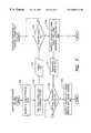
- FIG. 7illustrates one method of distributing an access key to the host 312 and the storage system 320 .
- Access keysmay be provided in a number of ways, including allocating access keys to the storage system and host processors in advance of their entry to the network. Alternatively, an access key may be obtained after the host processor has entered the network in a manner described with regard to the data flow diagram of FIG. 7 .
- FIG. 7operations performed by the HBA 345 (FIG. 6) are illustrated on the left hand side of the figure, operations performed by the storage system 320 are illustrated on the right hand side of the figure, and data flows are illustrated between the two sides.
- the HBA 345(FIG. 6) generates a public and private key pair. This can be done, for example, using known encryption software executing on the CPU 40 .
- the public and private key pairis dedicated to the HBA and is not accessible by any other device coupled to the network 21 (FIG. 6 ). Data which is encrypted by the public key 61 can only be decrypted using the private key 62 , while data that is encrypted by the private key 62 can only be decrypted using the public key 61 .
- the HBA 345forwards the public key 61 over to the storage system 320 .
- the storage system 320loops, waiting for the key.
- the storage system 320receives the public key at step 101 , it proceeds to step 103 .
- the storage system 320uses the public key 61 , the storage system 320 encrypts an access key for the HBA 345 , forwards this encrypted access key 67 back to the HBA 345 over the network 21 (FIG. 6) and terminates.
- the HBA 345is the only device in the network that has the private key 62 that must be used to decrypt any message encrypted with the public key, other devices that are monitoring the transactions on the network will not be able to decipher the encrypted access key 67 forwarded by the storage system 320 .
- the process running on the HBA 345proceeds to step 106 , wherein the HBA 345 decodes the encrypted access key using the private key 62 .
- the HBA 345stores the access key in data structure 60 with the public key 61 and private key 62 for later communications with the storage system 320 .
- the host processormay begin the process of issuing I/O requests to the storage system 320 .
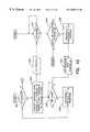
- the processes by which a host processor issues an I/O request, and by which an I/O request is serviced by the storage system 320 in accordance with one embodiment of the inventionwill now be described with regard to the flow diagrams of FIGS. 8 a-b and FIG. 9 .
- the methodproceeds to step 122 wherein in response to the host's request, the storage system 320 forwards a unique identifier 114 to the HBA 345 .
- the identifieris a random number provided in the destination session ID 64 of the payload portion 60 of the packet 50 as illustrated in FIG. 2 .
- the storage system 320encrypts the random number 114 using the access key and stores the encrypted random number for later comparison.
- the HBAWhen it is determined at step 123 that the HBA has received the random number from the storage system 320 , at step 124 the HBA encrypts the random number 114 using the access key 63 (obtained using the process of FIG. 7 ), and returns the random number to the storage system 320 as an encrypted number 125 .
- the storage system 320compares the received random number 125 against the previously encrypted and locally stored version of the random number generated at step 122 . The compare status 128 is forwarded to the HBA.
- the HBAis not permitted to access data at the storage system 320 , and the transaction is complete. If there is a match, then the host has the correct access key, and the correct random number and connection between the HBA and the storage system is authenticated.
- the HBAmay send an I/O request to the storage system 320 for servicing.
- every I/O transactionis authenticated using a different identifier (e.g. random number).
- the HBAkeeps track of the outstanding I/O requests using a technique referred to as command tag queuing.
- Each I/O requestis assigned a unique tag, using the source session ID field 62 (FIG. 2 ).
- the tagis included in the session ID field of the response so that the response data may be aligned with the request using the tag.
- the HBArequests a number of random numbers equal to the maximum number of permissible outstanding I/O requests.
- the list of random numbersis stored as list 64 in data structure 60 (FIG. 6) of the HBA 345 and is additionally stored in the authentication table 86 of the filter and adapter unit 334 (FIG. 6) of the storage system 320 .
- each of the data structuresmay include a public key 89 a , which is a copy of the public key 61 that was provided by the HBA to obtain the initial access key 63 .
- the data structure 89may include an access key 89 b , which is a copy of the access key 63 stored at HBA 345 .
- each of the data structuresfurther includes a list of random numbers. The random number in each entry of the data structure 89 c corresponds to a random number that will be used to authenticate an associated transaction. How the random number is used to authenticate a transaction is described in more detail with regard to FIG. 8 b.
- the HBA 345checks to determine whether there is an outstanding I/O request. If so, at step 192 , the HBA 345 encrypts the first random number using the access key, stored in field 63 of the data structure 60 . The HBA 345 then inserts the encrypted random number in the source session ID field of the I/O request packet, and forwards the I/O request packet 194 to the storage system 320 .
- the HBAretrieves the non-encrypted random number from the session ID fields of the packet 197 and stores the random number in the data structure 60 . The process then proceeds to step 190 , where the HBA initiates the next I/O request, using the next random number from the random number list 64 encrypted using the access key.
- a methodis provided wherein unique identifiers are used to authenticate a host at a storage system.
- the methodhas been described using random numbers, it should be understood that this is not a requirement of the invention, and that any sequence of numbers that does not include a readily discernable pattern may alternatively be used.
- more than one HBAmay be simultaneously connected to the storage system 320 .
- identifiersare distributed to coupled HBAs, their sequence will similarly be distributed among the variety of HBAs that are coupled to the storage system 320 , thereby making the number distribution appear even more random and accordingly more secure.
- encryption techniqueshave been described, it is not a requirement of the invention that identifiers be encrypted prior to transfer.
- an authentication techniquemay be used which does not include identifiers for each request but encrypts the entire request using the access key. It is also envisioned that a different access key may be provided for each transaction.
- the present inventionmay incorporate any combination of these authentication techniques and is therefore not limited to the specific embodiments discussed above.
- the above techniquesmay be used to verify that a connection between an initiator and a target is authorized.
- techniquesare also used to ensure that the data that is received at the target is the data that was sent by the initiator. Accordingly, further security may be obtained by applying validation methods to ensure that commands and data are not corrupted during a transfer from the initiator to the target.
- the validation methodmay be provided to preclude other devices that are coupled to the network from interfering with transactions between the initiator and the target.
- a method for validating a data transfer between a source and a target over the networkincludes the step of maintaining, at both the target and the initiator, a digital signature of the transfer.
- the digital signatureis in the form of a checksum.
- Each byte of data that is transferred between a target and an initiatoris combined with the previous bytes of the transfer using a hashing function to form the checksum.
- the hashing functionmay be, for example, an exclusive OR function, or some derivative thereof.
- the data included in the signaturemay include only that data forwarded by the initiator to the target, only that data forwarded from the target to the initiator, or a combination thereof.
- FIG. 10a flow diagram of one embodiment of a method for validating a data transfer between an initiator and a target is shown.
- the flow diagramis similar to that described with regard to FIG. 8 b , but includes steps for validating the data transfer.
- it is determined at the initiatorwhether or not there are any I/O requests. If so, at step 202 , the initiator encrypts the random number associated with the transaction and forwards the I/O request, with the encrypted random number in the source session ID, to the target.
- the targetcompares the received encrypted number against a stored encrypted expected random to determine a match. If there is no match, the target does not respond.
- the targetforwards a new encrypted random number and response data to the target. Also, at step 206 , the target hashes the response data into the existing checksum to provide a new checksum to build the digital signature of the data transfer. The response 207 is received at the initiator in step 208 . At step 209 , the initiator also hashes the response data into the existing checksum to provide a new checksum to build the digital signature of the data transfer. The process of issuing I/O requests and generating checksums continues for the number of requests in the initiator/target connection. When it is determined at step 200 that there are no more requests, the process proceeds to the validation phase in step 210 , illustrated in FIG. 11 .
- the initiatorencrypts the checksum using the access key, and forwards the encrypted checksum 212 to the target.
- the targetreceives the encrypted checksum, at step 214 .
- the targetdecrypts the checksum and at step 218 the target compares the decrypted checksum with the checksum generated by the target.
- the targetsends a status packet 220 to the initiator indicating whether or not the checksums matched. If it is determined at step 222 at the transaction was valid (i.e, no data was corrupted), then the connection between the initiator and the target is completed. If the status 220 indicates that the transaction was not valid and that data was corrupted, then the initiator re-establishes the connection with the target and repeats the data transaction.
- a data management method and apparatusprovides three levels of data management. Filtering is provided to ensure that each host only accesses volumes of data for which it has privileges. Security may be incorporated using authentication methods to verify that each request was truly issued by the host indicated in the identifier of the request. Finally, validation may be provided to ensure that data is not corrupted during transit.
- a system using the data management method and apparatus of the present inventionmay incorporate one or more of these levels of data management independently, and thus the present invention is not limited to a system including all the recited data management techniques described above.
- Such a data management systemprovides increased control over data accesses by users at a host processor by limiting the data capable of being accessed by the host processor.
- users at a host processormay be capable of accessing all of the data allocated to the host processor (depending upon the privileges associated with the user), no user, not even a system administrator with the highest privilege at the host processor, is capable of accessing data that is not allocated to the host by the storage system, regardless of the privileges of the user on the host.
- a user interface for a system administratorcommunicates with a configuration database (e.g., configuration database 32 in FIG. 3) of a storage system to enable a user or another application program to view and manage the availability and assignment of data storage volumes to different hosts in a storage network.
- a configuration databasee.g., configuration database 32 in FIG. 3
- storage networkis used to describe any type of network in which at least one host (e.g., host processor 12 in FIG. 3) is coupled to at least one storage system (e.g., storage system 20 in FIG. 3) using a network connection that permits additional network devices (such as hosts, HBAs, storage systems, switches or hubs, etc) to be interconnected therewith.
- the user interfacepermits network devices to be viewed and managed using identifiers that are more meaningful to a user than a WWN.
- a graphical user interfaceis provided with which a user can graphically view the availability and assignment of data storage volumes to different hosts in a storage network.
- the GUIalso allows a user to graphically view the topology of the network (i.e., how network devices such as hosts, HBAs, storage systems, storage system adapters, etc., are interconnected in the network), and to graphically modify the topology of the network and/or the availability and assignment of storage volumes to different hosts in the network.
- the GUIpermits network devices and the availability and assignment of storage volumes on a storage system to be viewed, managed, and modified using an alias for each host/HBA pair that is more meaningful to a user than a WWN.
- a command line interface(CLI) that can be used to query the availability and assignment of data storage volumes to different hosts in the network.
- the command line interfaceallows a user or another application program to generate reports illustrating the topology of a storage network (i.e., how network devices such as hosts, HBAs, storage systems, storage system adapters, etc. are interconnected in the network), and to modify the topology of the network and/or the availability and assignment of storage volumes to different hosts in the network.
- the CLIpermits network devices and the availability and assignment of storage volumes on a storage system to be viewed, managed, and modified using the WWN of the device, or a more meaningful identifier that can be assigned by a user or by the storage system.
- Embodiments of a user interfacemay advantageously be implemented in software that executes on a central processing unit of a host, such as CPU 40 of host processor 12 (FIG. 3 ).
- the user interfaceis typically stored in the memory (e.g., memory 42 ) of the host processor, although the interface software may be stored on any computer readable medium, such as diskette, tape, CD-ROM, etc., that is accessible by the host processor.
- a Java-based graphical user interfaceis provided.
- a C-programming language based command line interface(CLI) is provided.
- CLIC-programming language based command line interface
- the present inventionis not limited to any particular software implementation, as any of a variety of implementations may be used.
- Embodiments of a user interface according to the present inventionmay advantageously be implemented on a single host, or on a number of hosts distributed throughout a storage network. Moreover, embodiments of the user interface may be used to view and manage the availability and assignment of storage volumes on a single storage system or on multiple storage systems. Because the user interface may be used to modify the connection and allocation of storage volumes to different host/HBA pairs, the user interface may include password protection so that only authorized personnel can access the interface. Alternatively, for security reasons, the ability to modify the connection and allocation of storage volumes to different hosts on the storage network may be limited to a particular host.
- the term “administrator host”is used to refer to any host on which the user interface is implemented and from which the availability and assignment of data storage volumes to different hosts can be modified.
- portions of the user interfacemay be installed on other hosts so that they may be able to view the storage topology of the network, without having the ability to modify connections and allocation of storage thereto.
- a configuration database(e.g., configuration database 32 , in FIG. 3) that is stored and maintained on a storage system to manage access within a storage network.
- the configuration database 32may include additional identification information, in addition to the WWN and/or source ID of the host/HBA, to facilitate the management of access in the storage network.
- the configuration databasemay include an alias for each host, HBA, and filter and adapter unit known to the storage system, as well as an alias for the storage system itself.
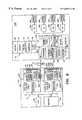
- FIG. 12illustrates an exemplary storage network 1200 that will be used to describe various aspects of the present invention. It should be appreciated that the network topology illustrated in FIG. 12 is exemplary only, as embodiments of the present invention can be used with network topologies that are different (e.g., more complex, or less complex) than that shown in FIG. 12 .
- a number of host processors 1212 , 1214are coupled to a storage system 1220 using a network 1221 .
- Host processor 1212has been assigned Internet Protocol (IP) node name “lo 10239 ”.
- IPInternet Protocol
- an IP node nameis an alphanumeric identifier for a network device that corresponds to a unique IP address that the network device uses to communicate with other network devices on an IP network.
- Host processor 1212includes two HBAs, HBA 1245 a and HBA 1245 b .
- Host processor 1214has been assigned IP node name “cohen 4554 b ” and includes a single HBA, HBA 1245 c .
- host processor cohen 4554 bis designated as the control station or administrator host, from which connection and access to storage is controlled.
- Storage system 1220is similar to the storage system 20 described above with respect to FIG. 3 . However, in contrast to the storage system 20 of FIG. 3, storage system 1220 includes a plurality of filter and adapter units 1234 a , 1234 b , and 1234 c , such as would typically be used in a larger network where many different hosts share the use of a central storage system 1220 .
- One such storage system that is representative of storage system 1220is the Symmetrix line of disk arrays available from EMC Corporation of Hopkinton, Mass. The Symmetrix line of disk arrays is described in numerous publications from EMC Corporation, including the Symmetrix Model 55XX product manual, P-N200-810-550, rev. F, February, 1996.
- each filter and adapter unit 1234 a , 1234 b , and 1234 chas its own connection to the network 1221 .
- Each filter and adapter unitmay include a number of ports, with each port supporting one or more connections to a host processor/HBA.
- each filter and adapter unitmay include two ports, with each port being capable of supporting up to 32 different connections to a host processor/HBA.
- Each of the filter and adapter unitscommunicates with the configuration database 1232 that is maintained by the storage system 1220 , and may include a processor and a memory, such as processor 80 and memory 83 described with respect to FIG. 3 .
- Multiple filter and adapter units, such as shown in FIG. 12,may be used to connect to different types of networks (e.g., a loop network or a fabric network), for fault tolerance reasons, to increase bandwidth, or for a variety of other reasons.
- configuration database 1232may include other information pertaining to network devices in the storage network in addition to that described above with respect to configuration database 32 in FIG. 3 .
- This additional informationcan include, for example, the IP node name of each host that is logged into the storage system 1220 , the IP node name of each host that has been assigned storage volumes in the storage system, or both.
- additional information pertaining to devices in the storage networkis stored in two different portions of the configuration database 1232 ; i.e., the history table 1269 and the configuration portion 1275 of the configuration database 1232 , including header portion 1270 , volume allocation portion 1272 , mapping portion 1274 , and filter table 1276 .
- the additional information that is stored in the history table 1269is maintained on a temporary basis for each host/HBA pair that is logged into a port of the storage system.
- the additional information that is stored in the configuration portion 1275is maintained on a permanent basis for each host/HBA pair for which access to storage volumes has been defined. It should be appreciated that the additional information pertaining to devices in the storage network need not be stored in different portions of the configuration database 1232 , as the present invention is not so limited.
- the additional information that is maintained in the history table 1269can include, for each host/HBA pair that is logged into a port on the storage system 1220 : the IP address of the host, the IP node name of the host, a time stamp indicative of the time at which the host/HBA pair logged into the port of the storage system, the type of file system used by the host, and an alias for the host/HBA pair that is logged into the particular port.
- the additional information that is maintained in the history table 1269can vary depending upon the type of network device (e.g., a host/HBA pair, a switch or hub, etc).
- a unique aliascan be automatically provided by the storage system for each host/HBA pair when the host/HBA pair logs into a port of the storage system.
- the unique aliasincludes the IP node name of the host and the name of the adapter that logged into the port.
- This aliascalled an ASCII World Wide Name (AWWN) herein, provides a short-hand identifier for each host/HBA that is logged into a port of the storage system, and is more meaningful to a user than a WWN. This is because the AWWN is logically related to identifiers (the IP node name of the host and the name of the adapter) that are used for other purposes, such as sending electronic mail, initializing devices in a startup file, etc.
- the AWWN that is maintained in the history table 1269can be used to view and manage network devices on a storage network and to control the availability and access to storage volumes on the storage system using embodiments of the user interface.
- a usercan view and manage network devices using an alias that is logically more descriptive than a WWN.
- a usercan assign a different alias to each host/HBA pair, should this be desired.
- the additional information that is stored in the configuration portion 1275 of the configuration database 1232can be the same or similar to the additional information provided in the history table 1269 , such as the IP node name of a host, the IP address of the host, and an alias of each host/HBA pair for which access to storage volumes has been previously defined.
- the information stored in the configuration portion 1275 of the configuration database 1232is maintained for each host/HBA pair for which access to storage volumes has been defined.
- the configuration portion 1275 of the configuration database 1232is scanned to determine if an alias for this host/HBA pair (or other type of network device) has been previously defined.
- an alias for a particular host/HBA pair (or other type of network device)has been previously defined in the configuration portion 1275 , that alias is automatically written into the history table 1269 along with its WWN and source ID.
- the information that is stored in the configuration database 1232may be stored in different areas of the storage system 1220 .
- the information stored in header portion 1270 , volume allocation portion 1272 , and mapping portion 1274 of the configuration database 1232is stored in one or more of the storage devices 1238 a - 1238 of the storage system 1220 , while the information stored in the history table 1269 and filter table portion 1276 is stored in a different type of memory device.
- the information stored in the history table 1269can be stored in a centrally accessible RAM or cache memory (not shown) of the storage system 1220
- the information stored in the filter table 1276can be stored in a transient filter table in a memory of a filter and adapter unit (e.g., transient filter table 84 in memory 83 of filter and adapter unit 34 in FIG. 3 ).
- transient filter table 84in memory 83 of filter and adapter unit 34 in FIG. 3
- those portions of the configuration database 1232 that are more frequently accessed and/or temporarycan be stored in RAM or cache, while those portions of the configuration database 1232 that are less frequently accessed and/or persistent (e.g., volume allocation portion 1270 ) can be stored on disk or other type of storage device.
- the present inventionis not limited to a particular manner in which the configuration database 1232 is apportioned, or to a particular type of memory device in which portions of the configuration database 1232 are stored, as other implementations may alternatively be used.
- a utilityfor providing additional identification information pertaining to hosts and host/HBA pairs that are logged into a storage system.
- the utilitymay be used to provide an alias for a host/HBA pair in the history table 1269 when one has not been previously defined in the configuration portion 1275 of the configuration database 1232 .
- the aliascan then be used to view and manage that host/HBA pair and to configure storage volume assignments therefor.
- the utilitymay be implemented in software that executes on the CPU of a host processor to include this additional information in the history table 1269 of the configuration database.
- the utilityqueries the host processor to determine information such as the IP node name of the host and the IP address of the host. Other information may also be obtained, such as the manufacturer of the host processor, the type of operating system (e.g., Unix, Windows NT, Sun SOLARIS) being used on the host, etc. After obtaining information relating to the host, the utility proceeds to step 1320 .
- the utilityqueries the storage network to identify those storage systems connected to the storage network that include a configuration database that facilitates shared access to storage resources, such as configuration database 1232 (FIG. 12 ). In a fabric storage network topology, this may be performed by accessing a nameserver on the fabric and examining the WWNs of devices that are connected thereto.
- each WWNincludes a portion that is unique to each device manufacturer
- the utilitycan examine the list of WWNs to identify those storage systems that are made by a particular manufacturer that include a configuration database 1232 .
- similar informationmay be obtained by querying each device in the loop and examining the WWNs of each device in a similar manner.
- the utilityUpon identifying those WWNs that identify storage systems that include a configuration database 1232 , the utility performs steps 1330 through 1380 for each such storage system.
- the utilitylogs into a port on a storage system having a configuration database 1232 and proceeds to step 1340 .
- the utilityexamines the history table 1269 in the configuration database 1232 to determine if an alias already exists for the particular host/HBA pair that the utility has caused to log into the storage system. When it is determined that the history table 1269 already includes an alias for this particular host/HBA pair, the. utility proceeds to step 1380 , described further below. Alternatively, when it is determined that the history table 1269 . does not include an alias for this particular host/HBA pair, the utility proceeds to step 1350 .
- the utilityexamines the configuration portion 1275 of the configuration database 1232 to determine if an alias has been defined therein for this particular host/HBA pair.
- the utilityproceeds to step 1360 , wherein the alias defined in the configuration portion 1275 is written into the history table 1269 .
- the utilityproceeds to step 1370 .
- the utilitycreates an alias for the host/HBA pair that is currently logged in to the storage system and writes it into the history table 1269 .
- the aliasincludes the IP host name of the host and the name of the adapter that logged into the port. This alias, called an ASCII World Wide Name (AWWN), provides a short-hand identifier for the host/HBA pair that has more meaning to a user than a WWN.
- the portion of the AWWN representing the adapter namevaries dependent upon the type of host (e.g, Windows NT, Sun SOLARIS, HP-UX, etc.) that logged into the port.
- the adapter portion of the AWWNis expressed in the form “adapterN”, where “N” is the logical number of the HBA adapter on the host.
- the adapter portion of the AWWNis expressed in the form “sbus, fca@adapter”, where “sbus” is the number of the bus on which the HBA resides, and “adapter” is the logical number of the adapter on the host.
- step 1380the utility returns to the host processor the information that is now stored in the history table 1269 of the configuration database 1232 .
- This informationwill include the AWWN of the host/HBA pair, as well as any AWWNs of other host/HBA pairs that are present in the history table 1269 (e.g., AWWNs that have been previously assigned through the use of the utility on a different host processor, etc.).
- the utilityalso provides the host processor with the WWN of the host/HBA pair that logged into the storage system, a port identifier of the port on which the host/HBA pair logged into the storage system, and the device name or path (in terms of the host system) by which the storage system was reached. After providing this information, the utility then terminates. It should be appreciated that in a storage network that includes more than one storage system having a configuration database 1232 , the utility will provide this information for each storage system that it is permitted to log into.
- the above utilityis capable of identifying each host/HBA pair that is presently logged into the storage system in terms of its WWN.
- a host/HBA pair that is logged into the storage systemhas been given an alias or AWWN
- the AWWN of each host/HBA pairis also provided.
- this information provided by the utilitycan then be used by the host on which the utility was executed to view and manage network devices on a storage network and to control the availability and access to storage volumes on the storage system with a user interface.
- a usercan view and manage network devices with the user interface using the AWWN, rather than the more arcane and cumbersome WWN.
- the utilitycan be used to identify the WWN of the HBA that the utility used to access the storage system. It should be appreciated that this ability to identify the WWN of an HBA that is connected to a network is of great use. Although the WWN of an HBA is typically indicated on the HBA itself, it may be difficult to view this information once the HBA is installed in a host processor. Moreover, although the WWN of an HBA may be identified in documentation that accompanied the HBA, such documentation is frequently lost or misplaced.
- the above-described utilityallows the WWN of a network device (e.g. a host/HBA pair) to be determined by requesting another network device (e.g., storage system 1220 ) to identify the WWN of the network device with which it is communicating.
- a network devicee.g. a host/HBA pair
- another network devicee.g., storage system 1220
- a user interfaceis now described, that, when executed on a processor (e.g., the CPU of a host processor), enables a user to view and manage devices in a storage network.
- a processore.g., the CPU of a host processor
- the Volume Logix product Guidedescribes an implementation of a system administrator, called “Volume Logix”, that includes a software based user interface that can be used on a wide variety of different host computer platforms, including personal computers, workstations, and mainframe computers running a wide variety of operating systems, such as Windows, Windows 95 or Windows NT, Unix, Unix-variants, etc.
- the user interfaceexecutes on a host processor and allows a user or another application program to query a storage system and define access control for storage volumes on that storage system for network devices on a storage network to which the storage system is attached.
- a user interfaceuses the user interface to identify various devices (storage systems, storage system port adapters, hosts, HBAs, etc.) in the storage network and understand the relationship of these devices to one another in the storage network. For example, one can view which host processors can communicate with a storage system, the path or physical connection by which they communicate, which storage volumes of data are accessible to a particular host processor or are shared among a number of host processors, etc.
- GUIgraphical user interface
- CLIcommand line interface
- the GUIgraphical user interface
- one of these interfacesone can display listings of devices, modify relationships of devices (e.g., assign, revoke, modify privileges on storage volumes for hosts that are connected to the network), etc.
- modify propertiesthat are associated with network devices. For example, one may modify the host name or the AWWN that is associated with a particular device.
- the Volume Logix Product Guidealso describes one exemplary implementation of a utility, called VCMFIND, that is similar in functionality to the utility described with respect to FIG. 13 .
- the VCMFIND utilitycan be used to identify, by WWN, each host/HBA pair that is logged into a storage system, to assign an alias or AWWN by which a host/HBA pair may be viewed and managed, and to provide a copy of the contents of the history table showing all other host/HBA pairs logged into a storage system to a host processor.
- This information returned to the host processor by the VCMFIND utilitycan be used in conjunction with embodiments of the user interface to permit the management of network devices through the use of the more meaningful alias or AWWN, rather than by use of the WWN.
- FIG. 14illustrates one exemplary implementation of a top-level display screen that can be provided by a graphical user interface (GUI) according to one embodiment of the present invention.
- GUIgraphical user interface
- the GUIWhen executed on a host processor, the GUI provides a management window 1400 to enable a user to view, configure, or modify the manner in which devices are connected to one another, and to view, configure, or modify the allocation and access to storage volumes on a storage system.
- the GUImay be executed on a host processor after a utility, such as that described above with respect to FIG. 13, was executed on each host processor (e.g., host processor cohen 455 b and host processor lo 10239 , in FIG. 12) for which management was desired.
- the execution of the utility of FIG. 13permits devices to be managed by an alias that is more meaningful than a WWN.
- the top level GUI management window 1400can include a number of components, such as a storage network topology pane 1410 , a storage system volumes view pane 1420 , a menu bar 1430 , a tool bar 1440 , and a status bar 1450 . It should be appreciated that the present invention is not limited to the particular arrangement of components shown in FIG. 14, as the GUI management window 1400 can be organized in many different ways.
- the storage network topology plane 1410can be used for viewing network devices and the topology of the storage network at varying levels of granularity.
- the volumes view pane 1420can be used to identify volumes of data stored on a particular storage system, to identify types of storage volumes stored on a particular storage system, whether those storage volumes are accessible by more that one host processor, etc.
- the menu bar 1430provides a set of pull down menus, 1460 - 1480 , that allow a user to manage and control devices connected to the storage network, including controlling which host processors can access storage volumes on the storage system.
- the tool bar 1440provides a quick access to some of the more frequently used options provided by the menu bar 1430 .
- the status bar 1450provides informational messages relating to current actions selected from the menu bar and the tool bar, such as whether tasks are pending, whether a task has been completed, etc.
- the GUI management window 1400displays devices, such as host processors, storage systems, host bus adapters, storage system adapters, etc, in a storage area network, with each device being represented by an easily recognizable icon.
- the GUI management window 1400also displays different types of storage volumes within a storage system by an easily recognizable icon.
- One exemplary illustration of how different types of storage area network devices and different types of storage volumes may be representedis shown in FIG. 15 . It should be appreciated that the present invention is not limited to any particular form of icon, as others may alternatively be used.
- Storage system icon 1505represents a storage system that is available on the storage network.
- the storage system icon 1505may be displayed in either a collapsed form or an expanded form, as described in more detail further below.
- Storage port icon 1510represents an adapter port (e.g., filter and adapter unit 1234 a-c in FIG. 12) on a storage system.
- the storage port icon 1505may be designated an FA (Fiber channel Adapter) port (See FIG. 14 ).
- FAFiber channel Adapter
- Host processor icon 1515represents a host processor that is available on the storage area network.
- the host processor icon 1515may also be displayed in either a collapsed form or an expanded form, as described in more detail further below.
- Administrator host icon 1520represents an administrator host processor or control station that is available on the storage area network and from which network devices and the allocation of storage devices in a storage system can be controlled or configured. The administrator host permits the allocation of volumes and the modification of how devices are connected in the storage network to be managed from a central control station or host processor. Like host processor icon 1515 , the administrator host icon 1520 may be displayed in either a collapsed form or an expanded form.
- Host Bus Adapter (HBA) icon 1525represents an HBA by which a host processor is connected to the storage area network. The HBA icon 1525 is displayed when the host processor icon 1515 or the administrator host icon 1520 is displayed in an expanded form.
- HBAHost Bus Adapter
- Storage volume icon 1530represents a storage volume in a storage system. More specifically, storage icon 1530 indicates that the represented volume is a standard fixed block addressing (FBA) volume that has not been allocated to a particular host processor/HBA pair (i.e., a storage volume for which no assignment has been defined in the configuration database 1232 (FIG. 12 ). Assigned storage volume icon 1535 represents a storage volume in a storage system that has been assigned to a particular host processor/HBA pair in the configuration database (i.e., configuration database 1232 , in FIG. 12) of the storage system. Shared, assigned, storage volume icon 1540 represents a storage volume in a storage system that has been assigned to more than one host processor/HBA pair in the configuration database 1232 of the storage system.
- FBAfixed block addressing
- Configuration database storage volume icon 1545represents that the particular storage volume stores the configuration database (called a Volume Configuration Management database, or VCM in one implementation).
- Mirrored storage volume icon 1550represents that the particular storage volume functions as a mirror to another storage volume (called a Business Continuity Volume, or BCV in one implementation).
- Concatenated storage volume icon 1555represents that the particular volume is one of a concatenated group of adjacent storage volumes that appear as one target volume (called a Meta Volume in one implementation).
- Other iconsmay be provided for other storage system resources.
- the use of different icons to represent various types of network devices and various types of storage volumesallows a detailed description of a storage network to be effectively communicated to a user.
- the storage network topology pane 1410provides a graphical representation of how network devices are arranged in a storage area network. This graphical representation uniquely identifies each network device in the storage area network and shows the path by which the network devices are interconnected. As described further below, this graphical representation of network devices can be displayed at varying levels of detail, selectable by a user.
- the storage network topology pane 1410shows paths between different host processor/HBA pairs and storage system/port pairs in the storage network that may be configured or modified using the graphical user interface. Dashed grey lines are used to represent paths that connect various devices in the storage network. Black solid lines are used to represent a path between network devices in which one of the network devices has been selected, for example, by using a mouse.
- host processor lo 10239has been selected in an expanded form, and thus, the path between this host processor, and its two HBAs (“1f, 0,fca@3,0,” and “1f,0,fca@1,0”) are shown in solid line form. As noted above with respect to FIG.
- the particular alias that is used to represent the HBAcan indicate the type of host processor to which the adapter is attached.
- Other ways of representing the above informationmay alternatively be used, as the present invention is not limited to a particular manner of representation.
- other network devicessuch as switches and hubs, that are not under the control of the graphical user interface, may also be depicted in the view presented by the storage network topology pane 1410 .
- Host processor/HBA pairsare shown on the left hand side of the storage network topology pane 1410 , with storage systems shown on the right.
- two host processors cohen 4554 b and lo 10239are shown in the left hand side of the storage network topology pane 1410 , with a storage system 01836000314 shown on the right.
- Each type of device(network device or a device within storage system) is represented by an icon that identifies the type of network device or the type of storage volume, as described above with respect to FIG. 15 .
- each iconincludes some associated text that uniquely identifies the particular device that the icon represents within the storage area network.
- the text that is associated with each host processor icon and HBA iconis based on the alias information of the history table 1269 (FIG. 12 ).
- the host processor icons of host processor cohen 4554 b and host processor lo 10239are similar, but different.
- the host processor icon of host processor cohen 4554 bincludes an “A” 1485 indicating that the host processor cohen 4554 b has been designated as the “administrator host” or control station on which the GUI is executed, and from which network devices and the allocation of storage devices can be centrally controlled or configured.
- the icons for host processors and for storage systemscan be displayed in either a collapsed form or an expanded form that is selectable by the user.
- a collapsed host iconhides the HBAs attached thereto, whereas an expanded host icon shows each of the HBAs that are attached to the host processor.
- Each of the host processor icons depicted in FIG. 14is displayed in its expanded form, showing its attachment to a particular HBA on a respective host processor.
- the host processor iconincludes a minus sign 1490 indicating that the collapsed form of the host processor icon may be selected by clicking on this region (termed a “hot spot”) of the icon.
- the collapsed formmay be selected by using a button associated with the tool bar 1440 , or by accessing a menu within the menu bar 1430 .
- a host processor iconWhen a host processor icon is collapsed, path connections between the host processor and other devices in the storage network are drawn directly from the host processor to the storage system or storage system port, depending on whether the storage system is shown in its collapsed or expanded form.
- the host processor iconWhen depicted in a collapsed form, the host processor icon includes a plus sign ( 1715 in FIG. 17) indicating that the expanded form of the host processor icon may alternatively be selected.
- Storage system iconscan also be shown in either a collapsed form or an expanded form.
- a collapsed storage systemhides the ports residing on it, while an expanded storage system shows each port residing on the storage system.
- path connectionsare drawn directly from the storage system to the host or HBA.
- path connectionsare drawn from the storage system to the port and then to the host for HBA.
- storage system 0183600314is shown in an expanded form.
- a collapsed storage system iconcan include a plus sign indicating that the expanded form of the storage system icon may alternatively be displayed upon selection, and an expanded storage system icon can include a minus sign indicating the collapsed form of the storage system icon may alternatively be displayed upon selection.
- Each host bus adapter icon(e.g., adapter 0 ) represents a particular HBA on which a host processor communicates to the storage network.
- Each HBAis identified using an icon and the adapter portion of the ASCII readable WWN (AWWN) that is stored in the history table 1269 of the configuration database 1232 (FIG. 12 ).
- the AWWNcan be assigned using a utility such as that described with respect to FIG. 13, or can be assigned automatically when a host/HBA pair logs into the storage system and the AWWN has been previously defined in the configuration portion 1275 of the configuration database 1232 .
- a usercan change the AWWN that is assigned to a particular host/HBA pair in the configuration portion 1275 of the configuration database 1232 using the GUI.
- the naming convention used to identify host processors and HBAs shown in FIG. 14was provided by using the utility of FIG. 13, prior to invoking the GUI.
- the name of the HBA assigned to a particular HBAcan vary, based on the type of operating system used by the host processor to which it is attached.
- host processor cohen 4554 bcommunicates with the network using HBA adapter 0
- host processor lo 101239communicates with the network using two different HBAs, “1f, 0,fca@3,0,” and “1f,0,fca@1,0.”
- dashed grey linesare used to represent paths that connect various devices in the storage network topology view pane 1410
- black solid linesindicate a selected connection (i.e. a connection between a selected device and another device).
- host processor lo 10239has been selected in an expanded form, and thus, the path between this host processor, and its two HBAs are shown in solid line form.
- the storage network topology view pane 1410allows a user to view the network topology at different levels of granularity. For example, one can view connections from a host processor to a storage system, from a host processor/HBA pair to the storage system, from a host processor to a particular port on the storage system, or from a host processor/HBA pair to a particular port on the storage system.
- This ability to display different levels of granularitypermits one to effectively manage access control in a top to bottom manner, from a host down to its HBA ports and from a storage system down to its ports and storage volumes.
- a userpermits a user to view the overall topology of a storage network, and then, selectively focus down to a particular set of devices within the network. It should be appreciated that the ability to graphically view a storage topology is particularly useful in larger storage area networks, where the network may include many more network devices than that shown in FIG. 14 .
- the storage system volumes view pane 1420graphically illustrates volumes of storage residing on a particular storage system.
- the storage volumes view pane 1420is filled when a network device, such as a host processor, an HBA, a host processor/HBA pair, or a storage system is selected in the storage network topology pane 1410 .
- the storage volume view pane 1420shows storage volumes that are available to or reside on the selected network device.
- the storage system volumes view pane 1420also graphically depicts other types of information, such as the type of storage volume, whether access rights in a storage volume have been assigned to a particular host processor/HBA pair, whether access rights in a storage volume have been assigned to multiple host processor/HBA pairs, etc. This information is obtained by the GUI accessing the configuration portion 1275 of the configuration database 1232 (FIG. 12 ).
- the icon viewdisplays an icon for each storage volume associated with the selected object. For example, in FIG. 14, an icon is displayed for each of storage volumes 0 - 22 residing on the selected storage system, storage system 0183600314 . Additional storage volumes, if present, may be viewed by expanding the window within which the volumes are shown, or by scrolling downward in a conventional manner. Where multiple storage systems are selected, storage volumes may be sorted by storage system number and then by storage volume, or in any other suitable way.
- storage volumes that have been assigned to a selected host processor/HBA pair and storage system/storage port pairare surrounded by a solid line border.
- storage volumes 3 - 8are surrounded by a solid line border to indicate that they have been assigned to a particular host processor/HBA pair and storage system/storage port pair that was selected by the user.
- thismay be indicated by a dashed line surrounding the affected volumes.
- a broken assignmentmay occur, for example, where an HBA has logged out from the network.
- other ways of representing the above identified information to a usermay alternatively be used, such as using one color to indicate a selected assignment, and another color to indicate a broken assignment.
- Each storage volume icon in the storage volumes view pane 1420may shown in one of a number of states.
- a gray storage volume icone.g., storage volume 1530 in FIG. 15
- storage volumes 0 - 2 and 9 - 22are displayed in an available state.
- a storage volumemay include highlighted black and white stripes (e.g., assigned storage volume 1535 in FIG. 15) to indicate that the storage volume is owned in a single-path configuration. That is, exactly one host/HBA pair has been assigned access rights to this particular volume.
- a storage volumecan be depicted with a blackened connector bar (e.g., shared assigned storage volume 1540 in FIG.
- the storage volume 15to indicate that the storage volume is a multi-path shared storage volume. That is, two or more hosts/HBA pairs have been assigned access rights to this particular storage volume.
- the icons used to represent storage volumes 3 - 8indicate that these volumes have been assigned access rights from multiple host processor/HBA pairs.
- FIG. 16illustrates a storage volumes view pane 1620 displayed in a detailed manner.
- the representation of each storage volume on the storage systemmay differ depending on whether access rights have been assigned to that volume, or upon whether a particular storage volume is assigned to a single host processor/HBA pair, or to multiple host processor/HBA pairs.
- the more detailed view of storage volumescan also identify the capacity of each storage volume, an identifier (e.g., name or serial number) of the storage system on which the storage volumes resides, an identifier of which ports on the storage system can access a particular volume, and the owner of that particular volume (i.e., what host processor/HBA pair(s) have access rights to a particular storage volume). It should be appreciated that the present invention is not limited to the information shown in FIG. 16, as different or additional information may alternatively be displayed.
- clicking on a devicee.g., pointing to a particular network device and selecting a particular button on a mouse or other pointing device
- highlights path connections associated with that device in the storage network topology view pane 1410and fills the storage volumes view pane 1420 with all volumes owned and possibly accessible to or residing on that device.
- This ability to graphically view a storage area network at varying degrees of detailpermits a user to effectively manage access control in a storage network in a hierarchical manner, from a host processor down to its ports.
- the menu bar 1430is positioned across the top of the management window 1400 in a conventional manner.
- the menu bar 1430includes five pull down menus, 1460 - 1480 , each providing the user with a number of options from which to select to perform various tasks.
- the File pull down menu 1460can include a run tasks option to execute queued operation such as adding or deleting access of a host/HBA pair to one or more storage volumes.
- the File pull down menu 1460can also include a properties option to display or modify properties (e.g., the name of a host or HBA, the name of a storage system or port, etc) of a selected network device, storage system or storage volume, and a report option that generates a report for a selected network device or storage volume.
- the report optionmay be used to generate information detailing the configuration of the storage network or the configuration of a particular device or volume, and this information can be either displayed or written to a file.
- the Edit menu 1465can provide a user with the ability to modify or delete a queued operation, or to change a login password to the graphical user interface.
- the View menu 1470may include an Icon/Details option that permits a user to toggle between icon-based and more detailed view of storage volumes, and a refresh display option that refreshes the work space to reflect storage volume assignments that are currently defined in the configuration portion 1275 of the configuration database 1232 , but have not been updated in the display screen 1400 .
- the Actions menu 1475may include various options categorized by the type of device (e.g., a storage system, a storage volume within a storage system, etc.) upon which they act.
- the Actions menu 1475can include a bus option that permits a user to define, clear, or swap access rights on a storage system bus, a volume option that adds, removes, or otherwise modifies access privileges to a storage volume, and a storage system option that can be used to perform operations on the configuration database, or to refresh the work space display.
- the menu bar 1430may also include a pull down Help menu 1480 that permits a user to display help file, display information about the particular software version of the configuration database code, or graphical user interface software, to set the path to an HTML based browser that is used to view help topics, etc. Other information may be provided using the Help menu 1480 , as the present invention is not limited to the particular topics for which additional information is provided, the organization of such information, or the particular manner in which it can be accessed.
- the GUI management window 1400may also include a tool bar 1440 that permits a user to quickly access some of the more frequently used features from the menu bar 1430 .
- the tool barmay include a properties icon 1405 to display a properties dialog box for currently selected items, a refresh display icon 1415 that reloads volume access assignments from the configuration portion 1275 of the configuration database 1232 , and a run tasks icon 1425 that commits all pending volume assignments for all storage systems, or for a selected storage system.
- the tool bar 1440may also include an iconic view icon 1435 that toggles between showing an iconic representation of storage volumes, or showing storage volumes in a more detailed fashion as described above.
- a details icon 1445may be provided that shows storage volume information in a more detailed tabular format, as in FIG.
- the tool bar 1440may also include a help icon 1455 that displays help files available to the user. It should be appreciated that other ways of providing a quick access to more frequently used features may also be provided, as the present invention is not limited to the particular implementation shown in FIG. 14 . For example, a sequence of keyboard commands (e.g., “control F”) may be used instead, or in addition to a tool bar.
- control Fa sequence of keyboard commands
- the status bar 1450is positioned across the bottom of the window 1400 and provides informational messages relating to current actions selected from the menu bar 1430 and the tool bar 1440 .
- the left hand side of the status bar 1450can indicate whether tasks are pending or completed, with the right hand side indicating the number of current tasks in the task list.
- Other ways of providing this informationmay alternatively be used, as the present invention is not limited to the particular implementation of the status bar 1450 shown in FIG. 14 .
- FIG. 17illustrates a storage network topology pane 1710 for a storage network that includes a number of different host processors as well as a number of storage systems.
- Each of the host processors except the host processor “pablo”is shown in a collapsed form.
- Host processor pablois shown in an expanded form, illustrating the path connection between the host processor pablo, the HBA port FcaPort 2 , and the storage system 9000003077 .
- Storage system 900003078is illustrated in a collapsed form, whereas storage system 9000003077 is illustrated in an expanded form, revealing each of the storage system port adapters accessible from the network.
- FIG. 18illustrates the storage network topology in which access rights to particular storage volumes will be provided for two different host processor systems, host processor cohen 4554 b and host processor lo 10239 . More particularly, FIG. 18 illustrates a management window 1800 that would be seen by a user after running a utility similar to that described in FIG. 13, such as the VCMFIND utility, on each of host processors cohen 4554 b and lo 10239 , and then executing the GUI on administrator host cohen 4554 b .
- a utility similar to that described in FIG. 13, such as the VCMFIND utilitysuch as the VCMFIND utility
- host processor cohen 4554 bwill be granted shared access to storage system 0183600314 , storage volume 4 , from HBA adapter 0 on host processor cohen 4554 b .
- Host processor lo 10239will be granted access to storage system 0183600314 , storage volumes 3 and 5 - 8 , from HBA adapter 1 on host processor lo 10239 , and will be granted shared access to storage volume 4 , from HBA adapter 2 on host processor lo 10239 .
- the userselects the storage system 0183600314 and expands the storage system icon to show all the storage adapter ports connected thereto. The result of these actions are shown in FIG. 19 .
- the volumes view pane 1920is filled in with all storage volumes residing on this storage system.
- the type of icon used to represent the storage volumes in the volumes view pane 1920 of FIG. 19none of the volumes of storage system 0183600314 have been assigned to a host processor.
- the storage adapter ports residing on the storage system 0183600314are displayed. Gray path connection lines are drawn from each storage system port to each host on the storage network that can connect thereto. As shown in storage network topology pane 1910 of FIG.
- the storage adapter ports residing on storage system 0183600314include Fibre Channel adapter ports (Fa) Fa 14 a , Fa 14 b , Fa 15 a , Fa 15 b , Fa 16 a and Fa 16 b .
- the selection of storage system 0183600314(for example, by clicking on the storage system icon using a mouse or other pointing device), results in the icon for storage system 0183600314 becoming highlighted.
- the selection and expansion of the icon for storage system 0183600314results in grey path lines being drawn between each storage system port on the selected storage system and the selected storage system (not shown).
- the selected portBy selecting a particular port that is attached to the storage system (e.g., port Fa 15 a ), the selected port becomes highlighted and the gray path lines from the storage system to the selected port become darkened (not shown). After selecting a particular storage system, all volumes on that storage system are displayed in the volumes view pane of the management window.
- a particular port that is attached to the storage systeme.g., port Fa 15 a
- the selected portbecomes highlighted and the gray path lines from the storage system to the selected port become darkened (not shown).
- host processor cohen 4554 bTo configure access to storage volume 4 on port Fa 15 a from HBA adapter 0 of host processor cohen 4554 b , the user then selects host processor cohen 4554 b by selecting the appropriate icon. Upon selection, host processor cohen 4554 b becomes highlighted and the formerly gray line from host processor cohen 4554 b to storage port Fa 15 a becomes solid black. By selecting the expanded form of host processor cohen 4554 b , (for example, by clicking on the plus sign in the host processor icon), the HBAs that are connected to host processor cohen 4554 b are displayed. The results of the preceding actions are shown in the storage network topology pane 2010 of FIG. 20, in which host processor cohen 4554 b is connected by a solid black line to a HBA adapter 0 .
- the userTo select storage volume 4 for allocation to host processor cohen 4554 b /adapter 0 , the user simply selects storage volume 4 icon. This is shown in the volumes view pane 2020 of FIG. 20 . After selecting a particular volume, the user may select the actions pull-down menu 2075 and select an option, such as add access. The result of these steps is to add access to storage volume 4 on storage system port Fa 15 a from HBA adapter 0 on host processor cohen 4554 b . Similar steps may be performed to add access to storage volume 4 on storage system port Fa 15 b from HBA adapter 0 on host processor cohen 4554 b . In one embodiment, after these steps are performed, a task list such as shown in FIG. 21 is displayed for the user. As shown in the task list of FIG.
- FIG. 22illustrates a graphical management window 2200 showing the assignment of storage volume 4 in volume view pane 2220 that a user would be provided with after performing the above steps.
- the selected storage volume in the volumes view pane 2220may be enclosed by a border to indicate that this volume has been selected.
- storage volume 4is represented by an assigned storage volume icon (i.e. assigned storage volume icon 1435 in FIG. 15 ).
- the paths shown in the storage network topology pane 2210 between host processor cohen 4554 b and HBA adapter 0 and storage volume 4via either of the storage system port adapters 15 a and 15 b , are shown in dark lines.
- a similar proceduremay be used to set up shared access to storage volume 4 from HBA adapter 2 of host processor lo 10239 and set up access to storage volumes 3 , and 5 - 8 from HBA adapter 1 of host processor lo 10239 .
- the resultant display after the management window has been refreshedis shown in FIG. 14, described previously above.
- a CLI based user interfaceis provided to manage network devices and manage and assign storage volumes to network device in a storage network.
- the CLI based user interfacecommunicates with a configuration database 1232 on a storage system 1220 to manage network devices and manage and assign storage volumes thereto.
- FPATHa CLI based user interface
- FIG. 12AOne exemplary implementation of a CLI based user interface, called FPATH, is described in great detail in the publication entitled, EMC Volume Logix Product Guide, as noted above. It should be appreciated that embodiments of the present invention directed to a CLI based user interface are not limited to the particular implementation of the FPATH CLI described therein, as the CLI based user interface of the present invention may be implemented in many different ways.
- the CLI based user interfaceis implemented in software and can be executed on a CPU 1240 of a host processor 1212 , 1214 .
- the CLIpermits network devices and storage volumes in a storage system to be managed using a WWN or, alternatively, using an AWWN that can be assigned to a particular network device.
- the CLI based user interfaceincludes a set of commands having the format “COMMAND action ⁇ arguments ⁇ , where COMMAND is a name of the executable CLI, for example “FPATH”, and where actions are subcommands that can be used to update the configuration database 1232 or display configuration information that is maintained in the configuration database 1232 of a storage system.
- Actions that may be performed on the configuration database 1232 of a storage system 1220include initializing the configuration database 1232 , adding or removing a network device such as a host, HBA or host/HBA pair to the configuration database 1232 so that network devices can access storage volumes on the storage system, adding or removing access to a particular storage port that a host/HBA pair can access on the storage system, and adding or removing access to a particular volume that a host/HBA pair can access on the storage system.
- a network devicesuch as a host, HBA or host/HBA pair
- Other actions that may be performed using the CLI based user interfaceinclude backing up the configuration database 1232 maintained by the storage system 1220 to a specified file, restoring the configuration database 1232 from the contents of such a backup file, providing an alias for a particular host/HBA pair that can be used in managing and configuring network devices on the storage network, etc.
- Display actions available using the CLIcan include displaying information relating to the manner in which network devices are related in the storage network. This information can include what devices are currently logged into a storage system, what access rights to storage volumes these network device have on the storage system, etc. This reporting information can be displayed on a display screen of a host processor, or saved to a file.
- the present inventionis not limited to the particular set of actions described above, as other actions, or additional actions may alternatively be provided.
- the CLI based user interfacemay be used in conjunction with a utility such as that described above with respect to FIG. 13 to manage network devices using more meaningful identifiers than their WWN.
- the CLI based user interfacecan thus have similar functionality to that described above for the GUI user interface. Accordingly, as the implementation of a CLI would be readily understood from the description of the GUI based user interface discussed above, further details of the CLI based user interface are omitted herein.
Landscapes
- Engineering & Computer Science (AREA)
- Computer Security & Cryptography (AREA)
- Computer Networks & Wireless Communication (AREA)
- Signal Processing (AREA)
- Computer Hardware Design (AREA)
- Computing Systems (AREA)
- General Engineering & Computer Science (AREA)
- Information Retrieval, Db Structures And Fs Structures Therefor (AREA)
Abstract
Description
Claims (20)
Priority Applications (1)
| Application Number | Priority Date | Filing Date | Title |
|---|---|---|---|
| US09/345,254US6665714B1 (en) | 1999-06-30 | 1999-06-30 | Method and apparatus for determining an identity of a network device |
Applications Claiming Priority (1)
| Application Number | Priority Date | Filing Date | Title |
|---|---|---|---|
| US09/345,254US6665714B1 (en) | 1999-06-30 | 1999-06-30 | Method and apparatus for determining an identity of a network device |
Publications (1)
| Publication Number | Publication Date |
|---|---|
| US6665714B1true US6665714B1 (en) | 2003-12-16 |
Family
ID=29711876
Family Applications (1)
| Application Number | Title | Priority Date | Filing Date |
|---|---|---|---|
| US09/345,254Expired - LifetimeUS6665714B1 (en) | 1999-06-30 | 1999-06-30 | Method and apparatus for determining an identity of a network device |
Country Status (1)
| Country | Link |
|---|---|
| US (1) | US6665714B1 (en) |
Cited By (144)
| Publication number | Priority date | Publication date | Assignee | Title |
|---|---|---|---|---|
| US20010047460A1 (en)* | 2000-04-25 | 2001-11-29 | Naotaka Kobayashi | Remote copy system of storage systems connected to fibre network |
| US20020004835A1 (en)* | 2000-06-02 | 2002-01-10 | Inrange Technologies Corporation | Message queue server system |
| US20020052938A1 (en)* | 2000-09-22 | 2002-05-02 | Kyocera Corporation | Network device management method, and network devices |
| US20020073257A1 (en)* | 2000-12-07 | 2002-06-13 | Ibm Corporation | Transferring foreign protocols across a system area network |
| US20020103631A1 (en)* | 2000-04-21 | 2002-08-01 | Anja Feldmann | Traffic engineering system and method |
| US20020103913A1 (en)* | 2001-01-26 | 2002-08-01 | Ahmad Tawil | System and method for host based target device masking based on unique hardware addresses |
| US20020147814A1 (en)* | 2001-04-05 | 2002-10-10 | Gur Kimchi | Multimedia devices over IP |
| US20020156828A1 (en)* | 2001-04-24 | 2002-10-24 | Takeshi Ishizaki | Integrated service management system |
| US20020161871A1 (en)* | 2001-04-25 | 2002-10-31 | Sunil Shanthaveeraiah | Persistent repository for on-demand node creation for fabric devices |
| US20020161933A1 (en)* | 2001-04-25 | 2002-10-31 | Sunil Shanthaveeraiah | System and method for on-demand node creation for fabric devices |
| US20020165946A1 (en)* | 2001-04-18 | 2002-11-07 | International Business Machines Corporation | Dynamic storage space linking |
| US20020194407A1 (en)* | 2001-04-25 | 2002-12-19 | Kim Hyon T. | Maintaining fabric device configuration through dynamic reconfiguration |
| US20020196744A1 (en)* | 2001-06-26 | 2002-12-26 | O'connor Michael A. | Path discovery and mapping in a storage area network |
| US20030018889A1 (en)* | 2001-07-20 | 2003-01-23 | Burnett Keith L. | Automated establishment of addressability of a network device for a target network enviroment |
| US20030023705A1 (en)* | 2001-04-25 | 2003-01-30 | Kim Hyon T. | Fabric device configuration interface |
| US20030033409A1 (en)* | 2001-08-10 | 2003-02-13 | King James E. | Secure network indentity allocation |
| US20030033389A1 (en)* | 2001-08-10 | 2003-02-13 | Simpson Shell Sterling | Detecting nearby devices in a network environment |
| US20030061382A1 (en)* | 2001-09-21 | 2003-03-27 | Dell Products L.P. | System and method for naming hosts in a distributed data processing system |
| US20030196055A1 (en)* | 2000-05-24 | 2003-10-16 | Toshimitsu Kamano | Method and apparatus for controlling access to storage device |
| US20030195953A1 (en)* | 2002-04-10 | 2003-10-16 | Masao Suzuki | Method and system for displaying the configuration of storage network |
| US20030204626A1 (en)* | 2002-04-24 | 2003-10-30 | Microsoft Corporation | Method and apparatus for efficiently matching responses to requests previously passed by a network node |
| US20030217212A1 (en)* | 2002-05-17 | 2003-11-20 | Kim Hyon T. | Device centric discovery and configuration for fabric devices |
| US20030233430A1 (en)* | 2002-06-13 | 2003-12-18 | International Business Machines Corporation | Method of modifying a logical library configuration from a remote management application |
| US20040015611A1 (en)* | 2002-06-25 | 2004-01-22 | Kim Hyon T. | Interfaces to multiple layers of device properties in a storage network |
| US20040059822A1 (en)* | 2002-09-25 | 2004-03-25 | Xiaoye Jiang | Network block services for client access of network-attached data storage in an IP network |
| US20040083285A1 (en)* | 2002-10-25 | 2004-04-29 | Alex Nicolson | Abstracted node discovery |
| US20040088366A1 (en)* | 2002-10-31 | 2004-05-06 | Mcdougall David | Storage area network mapping |
| US20040098474A1 (en)* | 2002-11-19 | 2004-05-20 | Salim Galou | Connection management system and graphical user interface for large-scale optical networks |
| US20040128311A1 (en)* | 2000-01-14 | 2004-07-01 | Hitachi, Ltd. | Security method and system for storage subsystem |
| US6769010B1 (en)* | 2000-05-11 | 2004-07-27 | Howzone.Com Inc. | Apparatus for distributing information over a network-based environment, method of distributing information to users, and method for associating content objects with a database wherein the content objects are accessible over a network communication medium by a user |
| US6779083B2 (en) | 2001-07-13 | 2004-08-17 | Hitachi, Ltd. | Security for logical unit in storage subsystem |
| US20040177287A1 (en)* | 2003-03-04 | 2004-09-09 | Yasunori Azuma | Tape library apparatus and controlling method thereof |
| US20040205179A1 (en)* | 2003-03-06 | 2004-10-14 | Hunt Galen C. | Integrating design, deployment, and management phases for systems |
| US6850253B1 (en)* | 2000-12-26 | 2005-02-01 | Nortel Networks Limited | Representing network link and connection information in a graphical user interface suitable for network management |
| US20050050356A1 (en)* | 2003-08-29 | 2005-03-03 | Sun Microsystems, Inc. | Secure transfer of host identities |
| US20050050185A1 (en)* | 2003-08-29 | 2005-03-03 | Sun Microsystems, Inc. | Transferring system identities |
| US6922414B1 (en)* | 2000-08-21 | 2005-07-26 | Hewlett-Packard Development Company, L.P. | Apparatus and method for dynamic command queue depth adjustment for storage area network nodes |
| US6941350B1 (en) | 2000-10-19 | 2005-09-06 | International Business Machines Corporation | Method and apparatus for reliably choosing a master network manager during initialization of a network computing system |
| US20050198631A1 (en)* | 2004-01-12 | 2005-09-08 | Dell Products L.P. | Method, software and system for deploying, managing and restoring complex information handling systems and storage |
| US6952734B1 (en) | 2000-08-21 | 2005-10-04 | Hewlett-Packard Development Company, L.P. | Method for recovery of paths between storage area network nodes with probationary period and desperation repair |
| US20050243717A1 (en)* | 2004-04-29 | 2005-11-03 | Jeremy Stieglitz | Controlling access message flow |
| US6963828B1 (en)* | 2001-03-21 | 2005-11-08 | Unisys Corporation | Metafarm sizer configuration optimization method for thin client sizing tool |
| US6971016B1 (en)* | 2000-05-31 | 2005-11-29 | International Business Machines Corporation | Authenticated access to storage area network |
| US6978300B1 (en) | 2000-10-19 | 2005-12-20 | International Business Machines Corporation | Method and apparatus to perform fabric management |
| US6981025B1 (en) | 2000-10-19 | 2005-12-27 | International Business Machines Corporation | Method and apparatus for ensuring scalable mastership during initialization of a system area network |
| US6990528B1 (en) | 2000-10-19 | 2006-01-24 | International Business Machines Corporation | System area network of end-to-end context via reliable datagram domains |
| US20060020792A1 (en)* | 2004-07-24 | 2006-01-26 | Weiss Jason R | Volume mount authentication |
| DE10197063B4 (en)* | 2000-12-22 | 2006-03-16 | Emc Corporation, Hopkinton | Method and device for preventing unauthorized access by a network device |
| US7039724B1 (en)* | 2000-03-09 | 2006-05-02 | Nortel Networks Limited | Programmable command-line interface API for managing operation of a network device |
| US7050961B1 (en)* | 2001-03-21 | 2006-05-23 | Unisys Corporation | Solution generation method for thin client sizing tool |
| US20060112173A1 (en)* | 2004-11-08 | 2006-05-25 | Internatonal Business Machines Corporation | Storage configuration loader |
| US7062426B1 (en)* | 2001-03-21 | 2006-06-13 | Unisys Corporation | Method for calculating memory requirements for thin client sizing tool |
| US7099955B1 (en) | 2000-10-19 | 2006-08-29 | International Business Machines Corporation | End node partitioning using LMC for a system area network |
| US20060212569A1 (en)* | 2005-03-18 | 2006-09-21 | International Business Machines Corporation | Dynamic discovery and reporting of one or more application program topologies in a single or networked distributed computing environment |
| US7113995B1 (en) | 2000-10-19 | 2006-09-26 | International Business Machines Corporation | Method and apparatus for reporting unauthorized attempts to access nodes in a network computing system |
| US7139821B1 (en)* | 2000-10-20 | 2006-11-21 | Sun Microsystems, Inc. | Method and apparatus for creating and deploying applications from a server application |
| US20060271579A1 (en)* | 2005-05-10 | 2006-11-30 | Arun Batish | Storage usage analysis |
| US7171410B1 (en)* | 2001-06-02 | 2007-01-30 | Redback Networks, Inc. | Fault tolerant network element |
| US20070094378A1 (en)* | 2001-10-05 | 2007-04-26 | Baldwin Duane M | Storage Area Network Methods and Apparatus with Centralized Management |
| US20070156877A1 (en)* | 2006-01-03 | 2007-07-05 | Sriram Krishnan | Server identification in storage networks |
| US20070168559A1 (en)* | 2003-01-14 | 2007-07-19 | Hitachi, Ltd. | SAN/NAS integrated storage system |
| US20070176246A1 (en)* | 2006-01-31 | 2007-08-02 | Advanced Micro Devices, Inc. | SRAM cells including self-stabilizing transistor structures |
| US7328298B2 (en)* | 2000-02-24 | 2008-02-05 | Fujitsu Limited | Apparatus and method for controlling I/O between different interface standards and method of identifying the apparatus |
| US20080034393A1 (en)* | 2006-08-02 | 2008-02-07 | Aaron Crayford | Distribution of content and advertisement |
| US20080043764A1 (en)* | 2001-04-24 | 2008-02-21 | Hitachi, Ltd. | Integrated service management system |
| US20080052628A1 (en)* | 2006-08-22 | 2008-02-28 | Bugenhagen Michael K | System and method for displaying a graphical representation of a network to identify nodes and node segments on the network that are not operating normally |
| US7376742B1 (en)* | 2002-03-22 | 2008-05-20 | Cisco Technology, Inc. | Resource and AAA service device |
| US20080126963A1 (en)* | 2006-06-30 | 2008-05-29 | Samsung Electronics Co., Ltd. | User terminal to manage driver and network port and method of controlling the same |
| US7401139B1 (en)* | 2000-09-07 | 2008-07-15 | International Business Machines Corporation | Storage area network management and configuration method and apparatus via enabling in-band communications |
| US20080294819A1 (en)* | 2007-05-24 | 2008-11-27 | Mouser Richard L | Simplify server replacement |
| US20080294672A1 (en)* | 2007-05-23 | 2008-11-27 | International Business Machines Corporation | System and method for disclosing relations between entities in support of information technology system visualization and management |
| US20090026521A1 (en)* | 2004-07-30 | 2009-01-29 | Frank Wirbeleit | Self-biasing transistor structure and an sram cell having less than six transistors |
| US7529249B1 (en) | 2002-03-22 | 2009-05-05 | Cisco Technology, Inc | Voice and dial service level agreement enforcement on universal gateway |
| US7552191B1 (en)* | 2001-06-12 | 2009-06-23 | F5 Networks, Inc. | Method and apparatus to facilitate automatic sharing in a client server environment |
| US7567504B2 (en) | 2003-06-30 | 2009-07-28 | Microsoft Corporation | Network load balancing with traffic routing |
| US7574343B2 (en) | 2000-10-24 | 2009-08-11 | Microsoft Corporation | System and method for logical modeling of distributed computer systems |
| US7590740B1 (en) | 2002-03-22 | 2009-09-15 | Cisco Technology, Inc. | Expediting port release in distributed networks |
| US7590736B2 (en) | 2003-06-30 | 2009-09-15 | Microsoft Corporation | Flexible network load balancing |
| US7606898B1 (en) | 2000-10-24 | 2009-10-20 | Microsoft Corporation | System and method for distributed management of shared computers |
| US7606929B2 (en) | 2003-06-30 | 2009-10-20 | Microsoft Corporation | Network load balancing with connection manipulation |
| US7613822B2 (en) | 2003-06-30 | 2009-11-03 | Microsoft Corporation | Network load balancing with session information |
| US7630877B2 (en)* | 2003-03-06 | 2009-12-08 | Microsoft Corporation | Architecture for distributed computing system and automated design, deployment, and management of distributed applications |
| US7636917B2 (en) | 2003-06-30 | 2009-12-22 | Microsoft Corporation | Network load balancing with host status information |
| US7636772B1 (en) | 2000-10-19 | 2009-12-22 | International Business Machines Corporation | Method and apparatus for dynamic retention of system area network management information in non-volatile store |
| US7657727B2 (en) | 2000-01-14 | 2010-02-02 | Hitachi, Ltd. | Security for logical unit in storage subsystem |
| US7669235B2 (en) | 2004-04-30 | 2010-02-23 | Microsoft Corporation | Secure domain join for computing devices |
| US7702762B1 (en)* | 2000-10-11 | 2010-04-20 | International Business Machines Corporation | System for host-to-host connectivity using ficon protocol over a storage area network |
| US7778422B2 (en) | 2004-02-27 | 2010-08-17 | Microsoft Corporation | Security associations for devices |
| US7802144B2 (en) | 2005-04-15 | 2010-09-21 | Microsoft Corporation | Model-based system monitoring |
| US20110012902A1 (en)* | 2009-07-16 | 2011-01-20 | Jaganathan Rajagopalan | Method and system for visualizing the performance of applications |
| US7890543B2 (en) | 2003-03-06 | 2011-02-15 | Microsoft Corporation | Architecture for distributed computing system and automated design, deployment, and management of distributed applications |
| US20110080772A1 (en)* | 2008-01-31 | 2011-04-07 | Globalfoundries Inc. | Body Controlled Double Channel Transistor and Circuits Comprising the Same |
| US7940735B2 (en) | 2006-08-22 | 2011-05-10 | Embarq Holdings Company, Llc | System and method for selecting an access point |
| US7941309B2 (en) | 2005-11-02 | 2011-05-10 | Microsoft Corporation | Modeling IT operations/policies |
| US7948909B2 (en) | 2006-06-30 | 2011-05-24 | Embarq Holdings Company, Llc | System and method for resetting counters counting network performance information at network communications devices on a packet network |
| US8000318B2 (en) | 2006-06-30 | 2011-08-16 | Embarq Holdings Company, Llc | System and method for call routing based on transmission performance of a packet network |
| US8015294B2 (en) | 2006-08-22 | 2011-09-06 | Embarq Holdings Company, LP | Pin-hole firewall for communicating data packets on a packet network |
| US8040811B2 (en) | 2006-08-22 | 2011-10-18 | Embarq Holdings Company, Llc | System and method for collecting and managing network performance information |
| US8064391B2 (en) | 2006-08-22 | 2011-11-22 | Embarq Holdings Company, Llc | System and method for monitoring and optimizing network performance to a wireless device |
| US8068425B2 (en) | 2008-04-09 | 2011-11-29 | Embarq Holdings Company, Llc | System and method for using network performance information to determine improved measures of path states |
| US8098579B2 (en) | 2006-08-22 | 2012-01-17 | Embarq Holdings Company, LP | System and method for adjusting the window size of a TCP packet through remote network elements |
| US8102770B2 (en) | 2006-08-22 | 2012-01-24 | Embarq Holdings Company, LP | System and method for monitoring and optimizing network performance with vector performance tables and engines |
| US8107366B2 (en) | 2006-08-22 | 2012-01-31 | Embarq Holdings Company, LP | System and method for using centralized network performance tables to manage network communications |
| US8111692B2 (en) | 2007-05-31 | 2012-02-07 | Embarq Holdings Company Llc | System and method for modifying network traffic |
| US8125897B2 (en) | 2006-08-22 | 2012-02-28 | Embarq Holdings Company Lp | System and method for monitoring and optimizing network performance with user datagram protocol network performance information packets |
| US8130793B2 (en) | 2006-08-22 | 2012-03-06 | Embarq Holdings Company, Llc | System and method for enabling reciprocal billing for different types of communications over a packet network |
| US8144587B2 (en) | 2006-08-22 | 2012-03-27 | Embarq Holdings Company, Llc | System and method for load balancing network resources using a connection admission control engine |
| US8144586B2 (en) | 2006-08-22 | 2012-03-27 | Embarq Holdings Company, Llc | System and method for controlling network bandwidth with a connection admission control engine |
| US20120089725A1 (en)* | 2010-10-11 | 2012-04-12 | International Business Machines Corporation | Methods and systems for verifying server-storage device connectivity |
| US8185960B1 (en) | 2006-07-27 | 2012-05-22 | Qlogic, Corporation | System and method for managing access to adapter features |
| US8184549B2 (en) | 2006-06-30 | 2012-05-22 | Embarq Holdings Company, LLP | System and method for selecting network egress |
| US8189468B2 (en) | 2006-10-25 | 2012-05-29 | Embarq Holdings, Company, LLC | System and method for regulating messages between networks |
| US8194643B2 (en) | 2006-10-19 | 2012-06-05 | Embarq Holdings Company, Llc | System and method for monitoring the connection of an end-user to a remote network |
| US8194555B2 (en) | 2006-08-22 | 2012-06-05 | Embarq Holdings Company, Llc | System and method for using distributed network performance information tables to manage network communications |
| US8199653B2 (en) | 2006-08-22 | 2012-06-12 | Embarq Holdings Company, Llc | System and method for communicating network performance information over a packet network |
| US20120179776A1 (en)* | 2011-01-12 | 2012-07-12 | Fujitsu Limited | Communication control apparatus, communication system, information processing apparatus, and communication control method |
| US8224255B2 (en) | 2006-08-22 | 2012-07-17 | Embarq Holdings Company, Llc | System and method for managing radio frequency windows |
| US8223655B2 (en) | 2006-08-22 | 2012-07-17 | Embarq Holdings Company, Llc | System and method for provisioning resources of a packet network based on collected network performance information |
| US8228791B2 (en) | 2006-08-22 | 2012-07-24 | Embarq Holdings Company, Llc | System and method for routing communications between packet networks based on intercarrier agreements |
| US8238253B2 (en) | 2006-08-22 | 2012-08-07 | Embarq Holdings Company, Llc | System and method for monitoring interlayer devices and optimizing network performance |
| US8274905B2 (en) | 2006-08-22 | 2012-09-25 | Embarq Holdings Company, Llc | System and method for displaying a graph representative of network performance over a time period |
| US8289965B2 (en) | 2006-10-19 | 2012-10-16 | Embarq Holdings Company, Llc | System and method for establishing a communications session with an end-user based on the state of a network connection |
| US8307065B2 (en) | 2006-08-22 | 2012-11-06 | Centurylink Intellectual Property Llc | System and method for remotely controlling network operators |
| US8358580B2 (en) | 2006-08-22 | 2013-01-22 | Centurylink Intellectual Property Llc | System and method for adjusting the window size of a TCP packet through network elements |
| US8374090B2 (en) | 2006-08-22 | 2013-02-12 | Centurylink Intellectual Property Llc | System and method for routing data on a packet network |
| US8407765B2 (en) | 2006-08-22 | 2013-03-26 | Centurylink Intellectual Property Llc | System and method for restricting access to network performance information tables |
| US8464238B1 (en)* | 2006-01-31 | 2013-06-11 | Qlogic, Corporation | Method and system for managing storage area networks |
| US8489728B2 (en) | 2005-04-15 | 2013-07-16 | Microsoft Corporation | Model-based system monitoring |
| US8488447B2 (en) | 2006-06-30 | 2013-07-16 | Centurylink Intellectual Property Llc | System and method for adjusting code speed in a transmission path during call set-up due to reduced transmission performance |
| US8531954B2 (en) | 2006-08-22 | 2013-09-10 | Centurylink Intellectual Property Llc | System and method for handling reservation requests with a connection admission control engine |
| US8537695B2 (en) | 2006-08-22 | 2013-09-17 | Centurylink Intellectual Property Llc | System and method for establishing a call being received by a trunk on a packet network |
| US8549513B2 (en) | 2005-06-29 | 2013-10-01 | Microsoft Corporation | Model-based virtual system provisioning |
| US8576722B2 (en) | 2006-08-22 | 2013-11-05 | Centurylink Intellectual Property Llc | System and method for modifying connectivity fault management packets |
| US8601539B1 (en)* | 2006-09-06 | 2013-12-03 | Dell Software Inc. | Systems and methods for managing user permissions |
| US8619600B2 (en) | 2006-08-22 | 2013-12-31 | Centurylink Intellectual Property Llc | System and method for establishing calls over a call path having best path metrics |
| US8639827B1 (en) | 2010-04-23 | 2014-01-28 | Dell Software Inc. | Self-service systems and methods for granting access to resources |
| US8717911B2 (en) | 2006-06-30 | 2014-05-06 | Centurylink Intellectual Property Llc | System and method for collecting network performance information |
| US8743703B2 (en) | 2006-08-22 | 2014-06-03 | Centurylink Intellectual Property Llc | System and method for tracking application resource usage |
| US8750158B2 (en) | 2006-08-22 | 2014-06-10 | Centurylink Intellectual Property Llc | System and method for differentiated billing |
| US9094257B2 (en) | 2006-06-30 | 2015-07-28 | Centurylink Intellectual Property Llc | System and method for selecting a content delivery network |
| US9183560B2 (en) | 2010-05-28 | 2015-11-10 | Daniel H. Abelow | Reality alternate |
| US9479341B2 (en) | 2006-08-22 | 2016-10-25 | Centurylink Intellectual Property Llc | System and method for initiating diagnostics on a packet network node |
| US10990356B2 (en)* | 2019-02-18 | 2021-04-27 | Quantum Lock Technologies LLC | Tamper-resistant smart factory |
| US11503027B2 (en)* | 2018-11-21 | 2022-11-15 | Hewlett Packard Enterprise Development Lp | Validating configuration changes on a network device |
Citations (16)
| Publication number | Priority date | Publication date | Assignee | Title |
|---|---|---|---|---|
| US4672572A (en) | 1984-05-21 | 1987-06-09 | Gould Inc. | Protector system for computer access and use |
| US5271007A (en) | 1990-12-25 | 1993-12-14 | Fuji Xerox Co., Ltd. | Network system having controlled access to available resources |
| US5321695A (en) | 1991-05-01 | 1994-06-14 | Hewlett-Packard Company | Port arrival identification for computer network packets |
| US5455953A (en) | 1993-11-03 | 1995-10-03 | Wang Laboratories, Inc. | Authorization system for obtaining in single step both identification and access rights of client to server directly from encrypted authorization ticket |
| US5469576A (en) | 1993-03-22 | 1995-11-21 | International Business Machines Corporation | Front end for file access controller |
| US5742759A (en) | 1995-08-18 | 1998-04-21 | Sun Microsystems, Inc. | Method and system for facilitating access control to system resources in a distributed computer system |
| US5771354A (en) | 1993-11-04 | 1998-06-23 | Crawford; Christopher M. | Internet online backup system provides remote storage for customers using IDs and passwords which were interactively established when signing up for backup services |
| US5860137A (en) | 1995-07-21 | 1999-01-12 | Emc Corporation | Dynamic load balancing |
| US5872539A (en)* | 1996-05-29 | 1999-02-16 | Hughes Electronics Corporation | Method and system for providing a user with precision location information |
| US5889952A (en) | 1996-08-14 | 1999-03-30 | Microsoft Corporation | Access check system utilizing cached access permissions |
| US5999930A (en) | 1996-08-02 | 1999-12-07 | Hewlett-Packard Company | Method and apparatus for distributed control of a shared storage volume |
| US6061726A (en) | 1997-05-27 | 2000-05-09 | Novell, Inc. | Dynamic rights assignment apparatus and method using network directory services |
| US6105027A (en) | 1997-03-10 | 2000-08-15 | Internet Dynamics, Inc. | Techniques for eliminating redundant access checking by access filters |
| US6141701A (en) | 1997-03-13 | 2000-10-31 | Whitney; Mark M. | System for, and method of, off-loading network transactions from a mainframe to an intelligent input/output device, including off-loading message queuing facilities |
| US6161129A (en)* | 1997-09-30 | 2000-12-12 | At&T Corp. | Unlisted address messaging system |
| US6199112B1 (en)* | 1998-09-23 | 2001-03-06 | Crossroads Systems, Inc. | System and method for resolving fibre channel device addresses on a network using the device's fully qualified domain name |
- 1999
- 1999-06-30USUS09/345,254patent/US6665714B1/ennot_activeExpired - Lifetime
Patent Citations (16)
| Publication number | Priority date | Publication date | Assignee | Title |
|---|---|---|---|---|
| US4672572A (en) | 1984-05-21 | 1987-06-09 | Gould Inc. | Protector system for computer access and use |
| US5271007A (en) | 1990-12-25 | 1993-12-14 | Fuji Xerox Co., Ltd. | Network system having controlled access to available resources |
| US5321695A (en) | 1991-05-01 | 1994-06-14 | Hewlett-Packard Company | Port arrival identification for computer network packets |
| US5469576A (en) | 1993-03-22 | 1995-11-21 | International Business Machines Corporation | Front end for file access controller |
| US5455953A (en) | 1993-11-03 | 1995-10-03 | Wang Laboratories, Inc. | Authorization system for obtaining in single step both identification and access rights of client to server directly from encrypted authorization ticket |
| US5771354A (en) | 1993-11-04 | 1998-06-23 | Crawford; Christopher M. | Internet online backup system provides remote storage for customers using IDs and passwords which were interactively established when signing up for backup services |
| US5860137A (en) | 1995-07-21 | 1999-01-12 | Emc Corporation | Dynamic load balancing |
| US5742759A (en) | 1995-08-18 | 1998-04-21 | Sun Microsystems, Inc. | Method and system for facilitating access control to system resources in a distributed computer system |
| US5872539A (en)* | 1996-05-29 | 1999-02-16 | Hughes Electronics Corporation | Method and system for providing a user with precision location information |
| US5999930A (en) | 1996-08-02 | 1999-12-07 | Hewlett-Packard Company | Method and apparatus for distributed control of a shared storage volume |
| US5889952A (en) | 1996-08-14 | 1999-03-30 | Microsoft Corporation | Access check system utilizing cached access permissions |
| US6105027A (en) | 1997-03-10 | 2000-08-15 | Internet Dynamics, Inc. | Techniques for eliminating redundant access checking by access filters |
| US6141701A (en) | 1997-03-13 | 2000-10-31 | Whitney; Mark M. | System for, and method of, off-loading network transactions from a mainframe to an intelligent input/output device, including off-loading message queuing facilities |
| US6061726A (en) | 1997-05-27 | 2000-05-09 | Novell, Inc. | Dynamic rights assignment apparatus and method using network directory services |
| US6161129A (en)* | 1997-09-30 | 2000-12-12 | At&T Corp. | Unlisted address messaging system |
| US6199112B1 (en)* | 1998-09-23 | 2001-03-06 | Crossroads Systems, Inc. | System and method for resolving fibre channel device addresses on a network using the device's fully qualified domain name |
Non-Patent Citations (5)
| Title |
|---|
| "Bootstrap Protocol (BOOTP)", Network Working Group article by Croft et al., pp. 1-12, Sep. 1985.** |
| Fibre Channel Tutorials and Resources. InterOperability Lab, University of New Hampshire. 1998.** |
| International Search Report from International Patent Application PCT/US00/17557, filed Jun. 26, 2000. |
| Lampson, B.W., "Protection (computer system access)", Operating Systems Review, Jan. 1974, USA, vol. 8, No. 1, pp. 18-24, XP000980389, ISSN: 0163-5980. |
| Sutton, A.J., et al., Processors sharing and partitioning of main storage in the MP system:, IBM Technical Disclosure Bulletin, Oct. 1979, USA, vol. 22, No. 5, pp. 2009-2010, XP000955350, ISSN: 0018-8689. |
Cited By (265)
| Publication number | Priority date | Publication date | Assignee | Title |
|---|---|---|---|---|
| US7606806B2 (en) | 2000-01-14 | 2009-10-20 | Hitachi, Ltd. | Security method and system for storage subsystem |
| US6947938B2 (en) | 2000-01-14 | 2005-09-20 | Hitachi, Ltd. | Security method and system for storage subsystem |
| US20060161548A1 (en)* | 2000-01-14 | 2006-07-20 | Ryusuke Ito | Security method and system for storage subsystem |
| US7908459B2 (en) | 2000-01-14 | 2011-03-15 | Hitachi, Ltd. | Security for logical unit in storage subsystem |
| US8700587B2 (en) | 2000-01-14 | 2014-04-15 | Hitachi, Ltd. | Security method and system for storage subsystem |
| US20040133576A1 (en)* | 2000-01-14 | 2004-07-08 | Hitachi, Ltd. | Security method and system for storage subsystem |
| US20040128311A1 (en)* | 2000-01-14 | 2004-07-01 | Hitachi, Ltd. | Security method and system for storage subsystem |
| US20100082902A1 (en)* | 2000-01-14 | 2010-04-01 | Hitachi, Ltd. | Security for logical unit in storage subsystem |
| US7657727B2 (en) | 2000-01-14 | 2010-02-02 | Hitachi, Ltd. | Security for logical unit in storage subsystem |
| US7024410B2 (en) | 2000-01-14 | 2006-04-04 | Hitachi, Ltd. | Security method and system for storage subsystem |
| US7328298B2 (en)* | 2000-02-24 | 2008-02-05 | Fujitsu Limited | Apparatus and method for controlling I/O between different interface standards and method of identifying the apparatus |
| US7039724B1 (en)* | 2000-03-09 | 2006-05-02 | Nortel Networks Limited | Programmable command-line interface API for managing operation of a network device |
| US20020103631A1 (en)* | 2000-04-21 | 2002-08-01 | Anja Feldmann | Traffic engineering system and method |
| US7027448B2 (en) | 2000-04-21 | 2006-04-11 | At&T Corp. | System and method for deriving traffic demands for a packet-switched network |
| US20020101821A1 (en)* | 2000-04-21 | 2002-08-01 | Anja Feldmann | System and method for deriving traffic demands for a packet-switched network |
| US20010047460A1 (en)* | 2000-04-25 | 2001-11-29 | Naotaka Kobayashi | Remote copy system of storage systems connected to fibre network |
| US6769010B1 (en)* | 2000-05-11 | 2004-07-27 | Howzone.Com Inc. | Apparatus for distributing information over a network-based environment, method of distributing information to users, and method for associating content objects with a database wherein the content objects are accessible over a network communication medium by a user |
| US7680881B2 (en) | 2000-05-11 | 2010-03-16 | Knapp John R | Method for associating content objects with a database |
| US20060288072A1 (en)* | 2000-05-11 | 2006-12-21 | Howzone.Com, Inc. | Method for associating content objects with a database |
| US6968434B2 (en) | 2000-05-24 | 2005-11-22 | Hitachi, Ltd. | Method and apparatus for controlling access to storage device |
| US20030196055A1 (en)* | 2000-05-24 | 2003-10-16 | Toshimitsu Kamano | Method and apparatus for controlling access to storage device |
| US7130978B2 (en) | 2000-05-24 | 2006-10-31 | Hitachi, Ltd. | Method and apparatus for controlling access to storage device |
| US20040199736A1 (en)* | 2000-05-24 | 2004-10-07 | Toshimitsu Kamano | Method and apparatus for controlling access to storage device |
| US6971016B1 (en)* | 2000-05-31 | 2005-11-29 | International Business Machines Corporation | Authenticated access to storage area network |
| US20020004835A1 (en)* | 2000-06-02 | 2002-01-10 | Inrange Technologies Corporation | Message queue server system |
| US6952734B1 (en) | 2000-08-21 | 2005-10-04 | Hewlett-Packard Development Company, L.P. | Method for recovery of paths between storage area network nodes with probationary period and desperation repair |
| US6922414B1 (en)* | 2000-08-21 | 2005-07-26 | Hewlett-Packard Development Company, L.P. | Apparatus and method for dynamic command queue depth adjustment for storage area network nodes |
| US7401139B1 (en)* | 2000-09-07 | 2008-07-15 | International Business Machines Corporation | Storage area network management and configuration method and apparatus via enabling in-band communications |
| US7194526B2 (en)* | 2000-09-22 | 2007-03-20 | Kyocera Corporation | Network device management method, and network devices |
| US20020052938A1 (en)* | 2000-09-22 | 2002-05-02 | Kyocera Corporation | Network device management method, and network devices |
| US7702762B1 (en)* | 2000-10-11 | 2010-04-20 | International Business Machines Corporation | System for host-to-host connectivity using ficon protocol over a storage area network |
| US7113995B1 (en) | 2000-10-19 | 2006-09-26 | International Business Machines Corporation | Method and apparatus for reporting unauthorized attempts to access nodes in a network computing system |
| US6990528B1 (en) | 2000-10-19 | 2006-01-24 | International Business Machines Corporation | System area network of end-to-end context via reliable datagram domains |
| US6981025B1 (en) | 2000-10-19 | 2005-12-27 | International Business Machines Corporation | Method and apparatus for ensuring scalable mastership during initialization of a system area network |
| US6978300B1 (en) | 2000-10-19 | 2005-12-20 | International Business Machines Corporation | Method and apparatus to perform fabric management |
| US6941350B1 (en) | 2000-10-19 | 2005-09-06 | International Business Machines Corporation | Method and apparatus for reliably choosing a master network manager during initialization of a network computing system |
| US7099955B1 (en) | 2000-10-19 | 2006-08-29 | International Business Machines Corporation | End node partitioning using LMC for a system area network |
| US7636772B1 (en) | 2000-10-19 | 2009-12-22 | International Business Machines Corporation | Method and apparatus for dynamic retention of system area network management information in non-volatile store |
| US7139821B1 (en)* | 2000-10-20 | 2006-11-21 | Sun Microsystems, Inc. | Method and apparatus for creating and deploying applications from a server application |
| US7574343B2 (en) | 2000-10-24 | 2009-08-11 | Microsoft Corporation | System and method for logical modeling of distributed computer systems |
| US7606898B1 (en) | 2000-10-24 | 2009-10-20 | Microsoft Corporation | System and method for distributed management of shared computers |
| US7739380B2 (en) | 2000-10-24 | 2010-06-15 | Microsoft Corporation | System and method for distributed management of shared computers |
| US7711121B2 (en) | 2000-10-24 | 2010-05-04 | Microsoft Corporation | System and method for distributed management of shared computers |
| US20020073257A1 (en)* | 2000-12-07 | 2002-06-13 | Ibm Corporation | Transferring foreign protocols across a system area network |
| DE10197063B4 (en)* | 2000-12-22 | 2006-03-16 | Emc Corporation, Hopkinton | Method and device for preventing unauthorized access by a network device |
| US6850253B1 (en)* | 2000-12-26 | 2005-02-01 | Nortel Networks Limited | Representing network link and connection information in a graphical user interface suitable for network management |
| US20020103913A1 (en)* | 2001-01-26 | 2002-08-01 | Ahmad Tawil | System and method for host based target device masking based on unique hardware addresses |
| US6963828B1 (en)* | 2001-03-21 | 2005-11-08 | Unisys Corporation | Metafarm sizer configuration optimization method for thin client sizing tool |
| US7062426B1 (en)* | 2001-03-21 | 2006-06-13 | Unisys Corporation | Method for calculating memory requirements for thin client sizing tool |
| US7050961B1 (en)* | 2001-03-21 | 2006-05-23 | Unisys Corporation | Solution generation method for thin client sizing tool |
| US20020147814A1 (en)* | 2001-04-05 | 2002-10-10 | Gur Kimchi | Multimedia devices over IP |
| US7266596B2 (en)* | 2001-04-18 | 2007-09-04 | International Business Machines Corporation | Dynamic storage space linking |
| US20020165946A1 (en)* | 2001-04-18 | 2002-11-07 | International Business Machines Corporation | Dynamic storage space linking |
| US20020174211A1 (en)* | 2001-04-24 | 2002-11-21 | Takeshi Ishizaki | Integrated service management system |
| US20080043764A1 (en)* | 2001-04-24 | 2008-02-21 | Hitachi, Ltd. | Integrated service management system |
| US7379987B2 (en)* | 2001-04-24 | 2008-05-27 | Hitachi, Ltd. | Integrated service management system |
| US20020156828A1 (en)* | 2001-04-24 | 2002-10-24 | Takeshi Ishizaki | Integrated service management system |
| US7693980B2 (en) | 2001-04-24 | 2010-04-06 | Hitachi, Ltd. | Integrated service management system |
| US7962601B2 (en) | 2001-04-24 | 2011-06-14 | Hitachi, Ltd. | Intergrated service management system |
| US7099912B2 (en) | 2001-04-24 | 2006-08-29 | Hitachi, Ltd. | Integrated service management system |
| US20030023705A1 (en)* | 2001-04-25 | 2003-01-30 | Kim Hyon T. | Fabric device configuration interface |
| US20020194407A1 (en)* | 2001-04-25 | 2002-12-19 | Kim Hyon T. | Maintaining fabric device configuration through dynamic reconfiguration |
| US20020161933A1 (en)* | 2001-04-25 | 2002-10-31 | Sunil Shanthaveeraiah | System and method for on-demand node creation for fabric devices |
| US20020161871A1 (en)* | 2001-04-25 | 2002-10-31 | Sunil Shanthaveeraiah | Persistent repository for on-demand node creation for fabric devices |
| US7200646B2 (en)* | 2001-04-25 | 2007-04-03 | Sun Microsystems, Inc. | System and method for on-demand node creation for fabric devices |
| US6920491B2 (en) | 2001-04-25 | 2005-07-19 | Sun Microsystems, Inc. | Fabric device configuration interface for onlining fabric devices for use from a host system |
| US7171474B2 (en)* | 2001-04-25 | 2007-01-30 | Sun Microsystems, Inc. | Persistent repository for on-demand node creation for fabric devices |
| US7171410B1 (en)* | 2001-06-02 | 2007-01-30 | Redback Networks, Inc. | Fault tolerant network element |
| US7552191B1 (en)* | 2001-06-12 | 2009-06-23 | F5 Networks, Inc. | Method and apparatus to facilitate automatic sharing in a client server environment |
| US20020196744A1 (en)* | 2001-06-26 | 2002-12-26 | O'connor Michael A. | Path discovery and mapping in a storage area network |
| US7051167B2 (en) | 2001-07-13 | 2006-05-23 | Hitachi, Ltd. | Security for logical unit in storage subsystem |
| US7082503B2 (en) | 2001-07-13 | 2006-07-25 | Hitachi, Ltd. | Security for logical unit in storage system |
| US6779083B2 (en) | 2001-07-13 | 2004-08-17 | Hitachi, Ltd. | Security for logical unit in storage subsystem |
| US20050010735A1 (en)* | 2001-07-13 | 2005-01-13 | Ryuske Ito | Security for logical unit in storage system |
| US20030018889A1 (en)* | 2001-07-20 | 2003-01-23 | Burnett Keith L. | Automated establishment of addressability of a network device for a target network enviroment |
| US7313819B2 (en)* | 2001-07-20 | 2007-12-25 | Intel Corporation | Automated establishment of addressability of a network device for a target network environment |
| US20080025292A1 (en)* | 2001-08-10 | 2008-01-31 | King James E | Secure network identity allocation |
| US20030033409A1 (en)* | 2001-08-10 | 2003-02-13 | King James E. | Secure network indentity allocation |
| US20030033389A1 (en)* | 2001-08-10 | 2003-02-13 | Simpson Shell Sterling | Detecting nearby devices in a network environment |
| US7730173B2 (en)* | 2001-08-10 | 2010-06-01 | Hewlett-Packard Development Company, L.P. | Detecting nearby devices in a network environment |
| US20030061382A1 (en)* | 2001-09-21 | 2003-03-27 | Dell Products L.P. | System and method for naming hosts in a distributed data processing system |
| US8327004B2 (en)* | 2001-10-05 | 2012-12-04 | International Business Machines Corporation | Storage area network methods and apparatus with centralized management |
| US20070094378A1 (en)* | 2001-10-05 | 2007-04-26 | Baldwin Duane M | Storage Area Network Methods and Apparatus with Centralized Management |
| US7376742B1 (en)* | 2002-03-22 | 2008-05-20 | Cisco Technology, Inc. | Resource and AAA service device |
| US7529249B1 (en) | 2002-03-22 | 2009-05-05 | Cisco Technology, Inc | Voice and dial service level agreement enforcement on universal gateway |
| US7590740B1 (en) | 2002-03-22 | 2009-09-15 | Cisco Technology, Inc. | Expediting port release in distributed networks |
| US20030195953A1 (en)* | 2002-04-10 | 2003-10-16 | Masao Suzuki | Method and system for displaying the configuration of storage network |
| US7003567B2 (en)* | 2002-04-19 | 2006-02-21 | Hitachi, Ltd. | Method and system for displaying the configuration of storage network |
| US7206862B2 (en)* | 2002-04-24 | 2007-04-17 | Microsoft Corporation | Method and apparatus for efficiently matching responses to requests previously passed by a network node |
| US20030204626A1 (en)* | 2002-04-24 | 2003-10-30 | Microsoft Corporation | Method and apparatus for efficiently matching responses to requests previously passed by a network node |
| US6965951B2 (en) | 2002-05-17 | 2005-11-15 | Sun Microsystems, Inc. | Device centric discovery and configuration for fabric devices |
| US20030217212A1 (en)* | 2002-05-17 | 2003-11-20 | Kim Hyon T. | Device centric discovery and configuration for fabric devices |
| US20030233430A1 (en)* | 2002-06-13 | 2003-12-18 | International Business Machines Corporation | Method of modifying a logical library configuration from a remote management application |
| US7047286B2 (en)* | 2002-06-13 | 2006-05-16 | International Business Machines Corporation | Method of modifying a logical library configuration from a remote management application |
| US20040015611A1 (en)* | 2002-06-25 | 2004-01-22 | Kim Hyon T. | Interfaces to multiple layers of device properties in a storage network |
| US7475124B2 (en)* | 2002-09-25 | 2009-01-06 | Emc Corporation | Network block services for client access of network-attached data storage in an IP network |
| US20040059822A1 (en)* | 2002-09-25 | 2004-03-25 | Xiaoye Jiang | Network block services for client access of network-attached data storage in an IP network |
| US20040083285A1 (en)* | 2002-10-25 | 2004-04-29 | Alex Nicolson | Abstracted node discovery |
| US7249173B2 (en)* | 2002-10-25 | 2007-07-24 | Emulex Design & Manufacturing Corporation | Abstracted node discovery |
| US20040088366A1 (en)* | 2002-10-31 | 2004-05-06 | Mcdougall David | Storage area network mapping |
| US8019840B2 (en)* | 2002-10-31 | 2011-09-13 | Hewlett-Packard Development Company, L.P. | Storage area network mapping |
| US20050254421A1 (en)* | 2002-11-19 | 2005-11-17 | Fujitsu Limited | Connection management system and method for large-scale optical networks |
| US20040098474A1 (en)* | 2002-11-19 | 2004-05-20 | Salim Galou | Connection management system and graphical user interface for large-scale optical networks |
| US6957263B2 (en)* | 2002-11-19 | 2005-10-18 | Fujitsu Limited | Connection management system and graphical user interface for large-scale optical networks |
| WO2004046951A1 (en)* | 2002-11-19 | 2004-06-03 | Fujitsu Limited | Connection management system and graphical user interface for large-scale optical networks |
| US7697312B2 (en)* | 2003-01-14 | 2010-04-13 | Hitachi, Ltd. | SAN/NAS integrated storage system |
| US20070168559A1 (en)* | 2003-01-14 | 2007-07-19 | Hitachi, Ltd. | SAN/NAS integrated storage system |
| US20040177287A1 (en)* | 2003-03-04 | 2004-09-09 | Yasunori Azuma | Tape library apparatus and controlling method thereof |
| US7610432B2 (en)* | 2003-03-04 | 2009-10-27 | Sony Corporation | Method and apparatus for assigning alias node names and port names within a tape library |
| US7630877B2 (en)* | 2003-03-06 | 2009-12-08 | Microsoft Corporation | Architecture for distributed computing system and automated design, deployment, and management of distributed applications |
| US7886041B2 (en) | 2003-03-06 | 2011-02-08 | Microsoft Corporation | Design time validation of systems |
| US8122106B2 (en) | 2003-03-06 | 2012-02-21 | Microsoft Corporation | Integrating design, deployment, and management phases for systems |
| US20060025985A1 (en)* | 2003-03-06 | 2006-02-02 | Microsoft Corporation | Model-Based system management |
| US7890543B2 (en) | 2003-03-06 | 2011-02-15 | Microsoft Corporation | Architecture for distributed computing system and automated design, deployment, and management of distributed applications |
| US7890951B2 (en) | 2003-03-06 | 2011-02-15 | Microsoft Corporation | Model-based provisioning of test environments |
| US7792931B2 (en) | 2003-03-06 | 2010-09-07 | Microsoft Corporation | Model-based system provisioning |
| US20040205179A1 (en)* | 2003-03-06 | 2004-10-14 | Hunt Galen C. | Integrating design, deployment, and management phases for systems |
| US7567504B2 (en) | 2003-06-30 | 2009-07-28 | Microsoft Corporation | Network load balancing with traffic routing |
| US7590736B2 (en) | 2003-06-30 | 2009-09-15 | Microsoft Corporation | Flexible network load balancing |
| US7606929B2 (en) | 2003-06-30 | 2009-10-20 | Microsoft Corporation | Network load balancing with connection manipulation |
| US7613822B2 (en) | 2003-06-30 | 2009-11-03 | Microsoft Corporation | Network load balancing with session information |
| US7636917B2 (en) | 2003-06-30 | 2009-12-22 | Microsoft Corporation | Network load balancing with host status information |
| US7389411B2 (en)* | 2003-08-29 | 2008-06-17 | Sun Microsystems, Inc. | Secure transfer of host identities |
| US7444396B2 (en) | 2003-08-29 | 2008-10-28 | Sun Microsystems, Inc. | Transferring system identities |
| US20050050356A1 (en)* | 2003-08-29 | 2005-03-03 | Sun Microsystems, Inc. | Secure transfer of host identities |
| US20050050185A1 (en)* | 2003-08-29 | 2005-03-03 | Sun Microsystems, Inc. | Transferring system identities |
| US20050198631A1 (en)* | 2004-01-12 | 2005-09-08 | Dell Products L.P. | Method, software and system for deploying, managing and restoring complex information handling systems and storage |
| US7778422B2 (en) | 2004-02-27 | 2010-08-17 | Microsoft Corporation | Security associations for devices |
| US7673025B2 (en)* | 2004-04-29 | 2010-03-02 | Cisco Technology, Inc. | Controlling access message flow |
| US20050243717A1 (en)* | 2004-04-29 | 2005-11-03 | Jeremy Stieglitz | Controlling access message flow |
| US7669235B2 (en) | 2004-04-30 | 2010-02-23 | Microsoft Corporation | Secure domain join for computing devices |
| US7480931B2 (en) | 2004-07-24 | 2009-01-20 | Bbs Technologies, Inc. | Volume mount authentication |
| US20060020792A1 (en)* | 2004-07-24 | 2006-01-26 | Weiss Jason R | Volume mount authentication |
| USRE42382E1 (en)* | 2004-07-24 | 2011-05-17 | Bbs Technologies, Inc. | Volume mount authentication |
| US20090026521A1 (en)* | 2004-07-30 | 2009-01-29 | Frank Wirbeleit | Self-biasing transistor structure and an sram cell having less than six transistors |
| US7480702B2 (en)* | 2004-11-08 | 2009-01-20 | International Business Machines Corporation | Storage configuration loader |
| US20060112173A1 (en)* | 2004-11-08 | 2006-05-25 | Internatonal Business Machines Corporation | Storage configuration loader |
| US8028058B2 (en)* | 2005-03-18 | 2011-09-27 | International Business Machines Corporation | Dynamic discovery and reporting of one or more application program topologies in a single or networked distributed computing environment |
| US20060212569A1 (en)* | 2005-03-18 | 2006-09-21 | International Business Machines Corporation | Dynamic discovery and reporting of one or more application program topologies in a single or networked distributed computing environment |
| US7802144B2 (en) | 2005-04-15 | 2010-09-21 | Microsoft Corporation | Model-based system monitoring |
| US8489728B2 (en) | 2005-04-15 | 2013-07-16 | Microsoft Corporation | Model-based system monitoring |
| US20060271579A1 (en)* | 2005-05-10 | 2006-11-30 | Arun Batish | Storage usage analysis |
| US10540159B2 (en) | 2005-06-29 | 2020-01-21 | Microsoft Technology Licensing, Llc | Model-based virtual system provisioning |
| US8549513B2 (en) | 2005-06-29 | 2013-10-01 | Microsoft Corporation | Model-based virtual system provisioning |
| US9811368B2 (en) | 2005-06-29 | 2017-11-07 | Microsoft Technology Licensing, Llc | Model-based virtual system provisioning |
| US9317270B2 (en) | 2005-06-29 | 2016-04-19 | Microsoft Technology Licensing, Llc | Model-based virtual system provisioning |
| US7941309B2 (en) | 2005-11-02 | 2011-05-10 | Microsoft Corporation | Modeling IT operations/policies |
| US20070156877A1 (en)* | 2006-01-03 | 2007-07-05 | Sriram Krishnan | Server identification in storage networks |
| US8185639B2 (en)* | 2006-01-03 | 2012-05-22 | Emc Corporation | Server identification in storage networks |
| US8464238B1 (en)* | 2006-01-31 | 2013-06-11 | Qlogic, Corporation | Method and system for managing storage area networks |
| US20070176246A1 (en)* | 2006-01-31 | 2007-08-02 | Advanced Micro Devices, Inc. | SRAM cells including self-stabilizing transistor structures |
| US8000318B2 (en) | 2006-06-30 | 2011-08-16 | Embarq Holdings Company, Llc | System and method for call routing based on transmission performance of a packet network |
| US10230788B2 (en) | 2006-06-30 | 2019-03-12 | Centurylink Intellectual Property Llc | System and method for selecting a content delivery network |
| US7948909B2 (en) | 2006-06-30 | 2011-05-24 | Embarq Holdings Company, Llc | System and method for resetting counters counting network performance information at network communications devices on a packet network |
| US9549004B2 (en) | 2006-06-30 | 2017-01-17 | Centurylink Intellectual Property Llc | System and method for re-routing calls |
| US9118583B2 (en) | 2006-06-30 | 2015-08-25 | Centurylink Intellectual Property Llc | System and method for re-routing calls |
| US9094257B2 (en) | 2006-06-30 | 2015-07-28 | Centurylink Intellectual Property Llc | System and method for selecting a content delivery network |
| US9054915B2 (en) | 2006-06-30 | 2015-06-09 | Centurylink Intellectual Property Llc | System and method for adjusting CODEC speed in a transmission path during call set-up due to reduced transmission performance |
| US8976665B2 (en) | 2006-06-30 | 2015-03-10 | Centurylink Intellectual Property Llc | System and method for re-routing calls |
| US8717911B2 (en) | 2006-06-30 | 2014-05-06 | Centurylink Intellectual Property Llc | System and method for collecting network performance information |
| US9749399B2 (en) | 2006-06-30 | 2017-08-29 | Centurylink Intellectual Property Llc | System and method for selecting a content delivery network |
| US8570872B2 (en) | 2006-06-30 | 2013-10-29 | Centurylink Intellectual Property Llc | System and method for selecting network ingress and egress |
| US9154634B2 (en) | 2006-06-30 | 2015-10-06 | Centurylink Intellectual Property Llc | System and method for managing network communications |
| US20080126963A1 (en)* | 2006-06-30 | 2008-05-29 | Samsung Electronics Co., Ltd. | User terminal to manage driver and network port and method of controlling the same |
| US8488447B2 (en) | 2006-06-30 | 2013-07-16 | Centurylink Intellectual Property Llc | System and method for adjusting code speed in a transmission path during call set-up due to reduced transmission performance |
| US9838440B2 (en) | 2006-06-30 | 2017-12-05 | Centurylink Intellectual Property Llc | Managing voice over internet protocol (VoIP) communications |
| US10560494B2 (en) | 2006-06-30 | 2020-02-11 | Centurylink Intellectual Property Llc | Managing voice over internet protocol (VoIP) communications |
| US8477614B2 (en) | 2006-06-30 | 2013-07-02 | Centurylink Intellectual Property Llc | System and method for routing calls if potential call paths are impaired or congested |
| US8184549B2 (en) | 2006-06-30 | 2012-05-22 | Embarq Holdings Company, LLP | System and method for selecting network egress |
| US8185960B1 (en) | 2006-07-27 | 2012-05-22 | Qlogic, Corporation | System and method for managing access to adapter features |
| US7761900B2 (en)* | 2006-08-02 | 2010-07-20 | Clarendon Foundation, Inc. | Distribution of content and advertisement |
| US20080034393A1 (en)* | 2006-08-02 | 2008-02-07 | Aaron Crayford | Distribution of content and advertisement |
| US8144586B2 (en) | 2006-08-22 | 2012-03-27 | Embarq Holdings Company, Llc | System and method for controlling network bandwidth with a connection admission control engine |
| US9602265B2 (en) | 2006-08-22 | 2017-03-21 | Centurylink Intellectual Property Llc | System and method for handling communications requests |
| US8199653B2 (en) | 2006-08-22 | 2012-06-12 | Embarq Holdings Company, Llc | System and method for communicating network performance information over a packet network |
| US8213366B2 (en) | 2006-08-22 | 2012-07-03 | Embarq Holdings Company, Llc | System and method for monitoring and optimizing network performance to a wireless device |
| US20080052628A1 (en)* | 2006-08-22 | 2008-02-28 | Bugenhagen Michael K | System and method for displaying a graphical representation of a network to identify nodes and node segments on the network that are not operating normally |
| US8223654B2 (en) | 2006-08-22 | 2012-07-17 | Embarq Holdings Company, Llc | Application-specific integrated circuit for monitoring and optimizing interlayer network performance |
| US8224255B2 (en) | 2006-08-22 | 2012-07-17 | Embarq Holdings Company, Llc | System and method for managing radio frequency windows |
| US8223655B2 (en) | 2006-08-22 | 2012-07-17 | Embarq Holdings Company, Llc | System and method for provisioning resources of a packet network based on collected network performance information |
| US8228791B2 (en) | 2006-08-22 | 2012-07-24 | Embarq Holdings Company, Llc | System and method for routing communications between packet networks based on intercarrier agreements |
| US8238253B2 (en) | 2006-08-22 | 2012-08-07 | Embarq Holdings Company, Llc | System and method for monitoring interlayer devices and optimizing network performance |
| US8274905B2 (en) | 2006-08-22 | 2012-09-25 | Embarq Holdings Company, Llc | System and method for displaying a graph representative of network performance over a time period |
| US10469385B2 (en) | 2006-08-22 | 2019-11-05 | Centurylink Intellectual Property Llc | System and method for improving network performance using a connection admission control engine |
| US8307065B2 (en) | 2006-08-22 | 2012-11-06 | Centurylink Intellectual Property Llc | System and method for remotely controlling network operators |
| US10298476B2 (en) | 2006-08-22 | 2019-05-21 | Centurylink Intellectual Property Llc | System and method for tracking application resource usage |
| US8358580B2 (en) | 2006-08-22 | 2013-01-22 | Centurylink Intellectual Property Llc | System and method for adjusting the window size of a TCP packet through network elements |
| US8374090B2 (en) | 2006-08-22 | 2013-02-12 | Centurylink Intellectual Property Llc | System and method for routing data on a packet network |
| US8407765B2 (en) | 2006-08-22 | 2013-03-26 | Centurylink Intellectual Property Llc | System and method for restricting access to network performance information tables |
| US10075351B2 (en) | 2006-08-22 | 2018-09-11 | Centurylink Intellectual Property Llc | System and method for improving network performance |
| US8472326B2 (en) | 2006-08-22 | 2013-06-25 | Centurylink Intellectual Property Llc | System and method for monitoring interlayer devices and optimizing network performance |
| US9992348B2 (en) | 2006-08-22 | 2018-06-05 | Century Link Intellectual Property LLC | System and method for establishing a call on a packet network |
| US8144587B2 (en) | 2006-08-22 | 2012-03-27 | Embarq Holdings Company, Llc | System and method for load balancing network resources using a connection admission control engine |
| US8130793B2 (en) | 2006-08-22 | 2012-03-06 | Embarq Holdings Company, Llc | System and method for enabling reciprocal billing for different types of communications over a packet network |
| US8488495B2 (en) | 2006-08-22 | 2013-07-16 | Centurylink Intellectual Property Llc | System and method for routing communications between packet networks based on real time pricing |
| US8509082B2 (en) | 2006-08-22 | 2013-08-13 | Centurylink Intellectual Property Llc | System and method for load balancing network resources using a connection admission control engine |
| US9929923B2 (en) | 2006-08-22 | 2018-03-27 | Centurylink Intellectual Property Llc | System and method for provisioning resources of a packet network based on collected network performance information |
| US8520603B2 (en) | 2006-08-22 | 2013-08-27 | Centurylink Intellectual Property Llc | System and method for monitoring and optimizing network performance to a wireless device |
| US8531954B2 (en) | 2006-08-22 | 2013-09-10 | Centurylink Intellectual Property Llc | System and method for handling reservation requests with a connection admission control engine |
| US8537695B2 (en) | 2006-08-22 | 2013-09-17 | Centurylink Intellectual Property Llc | System and method for establishing a call being received by a trunk on a packet network |
| US8549405B2 (en)* | 2006-08-22 | 2013-10-01 | Centurylink Intellectual Property Llc | System and method for displaying a graphical representation of a network to identify nodes and node segments on the network that are not operating normally |
| US8125897B2 (en) | 2006-08-22 | 2012-02-28 | Embarq Holdings Company Lp | System and method for monitoring and optimizing network performance with user datagram protocol network performance information packets |
| US9832090B2 (en) | 2006-08-22 | 2017-11-28 | Centurylink Intellectual Property Llc | System, method for compiling network performancing information for communications with customer premise equipment |
| US8576722B2 (en) | 2006-08-22 | 2013-11-05 | Centurylink Intellectual Property Llc | System and method for modifying connectivity fault management packets |
| US9813320B2 (en) | 2006-08-22 | 2017-11-07 | Centurylink Intellectual Property Llc | System and method for generating a graphical user interface representative of network performance |
| US8619596B2 (en) | 2006-08-22 | 2013-12-31 | Centurylink Intellectual Property Llc | System and method for using centralized network performance tables to manage network communications |
| US8619600B2 (en) | 2006-08-22 | 2013-12-31 | Centurylink Intellectual Property Llc | System and method for establishing calls over a call path having best path metrics |
| US8619820B2 (en) | 2006-08-22 | 2013-12-31 | Centurylink Intellectual Property Llc | System and method for enabling communications over a number of packet networks |
| US9806972B2 (en) | 2006-08-22 | 2017-10-31 | Centurylink Intellectual Property Llc | System and method for monitoring and altering performance of a packet network |
| US8670313B2 (en) | 2006-08-22 | 2014-03-11 | Centurylink Intellectual Property Llc | System and method for adjusting the window size of a TCP packet through network elements |
| US8687614B2 (en) | 2006-08-22 | 2014-04-01 | Centurylink Intellectual Property Llc | System and method for adjusting radio frequency parameters |
| US8107366B2 (en) | 2006-08-22 | 2012-01-31 | Embarq Holdings Company, LP | System and method for using centralized network performance tables to manage network communications |
| US8102770B2 (en) | 2006-08-22 | 2012-01-24 | Embarq Holdings Company, LP | System and method for monitoring and optimizing network performance with vector performance tables and engines |
| US8743700B2 (en) | 2006-08-22 | 2014-06-03 | Centurylink Intellectual Property Llc | System and method for provisioning resources of a packet network based on collected network performance information |
| US8743703B2 (en) | 2006-08-22 | 2014-06-03 | Centurylink Intellectual Property Llc | System and method for tracking application resource usage |
| US8750158B2 (en) | 2006-08-22 | 2014-06-10 | Centurylink Intellectual Property Llc | System and method for differentiated billing |
| US8811160B2 (en) | 2006-08-22 | 2014-08-19 | Centurylink Intellectual Property Llc | System and method for routing data on a packet network |
| US9712445B2 (en) | 2006-08-22 | 2017-07-18 | Centurylink Intellectual Property Llc | System and method for routing data on a packet network |
| US9660917B2 (en) | 2006-08-22 | 2017-05-23 | Centurylink Intellectual Property Llc | System and method for remotely controlling network operators |
| US9661514B2 (en) | 2006-08-22 | 2017-05-23 | Centurylink Intellectual Property Llc | System and method for adjusting communication parameters |
| US8098579B2 (en) | 2006-08-22 | 2012-01-17 | Embarq Holdings Company, LP | System and method for adjusting the window size of a TCP packet through remote network elements |
| US9621361B2 (en) | 2006-08-22 | 2017-04-11 | Centurylink Intellectual Property Llc | Pin-hole firewall for communicating data packets on a packet network |
| US9014204B2 (en) | 2006-08-22 | 2015-04-21 | Centurylink Intellectual Property Llc | System and method for managing network communications |
| US9042370B2 (en) | 2006-08-22 | 2015-05-26 | Centurylink Intellectual Property Llc | System and method for establishing calls over a call path having best path metrics |
| US9054986B2 (en) | 2006-08-22 | 2015-06-09 | Centurylink Intellectual Property Llc | System and method for enabling communications over a number of packet networks |
| US8194555B2 (en) | 2006-08-22 | 2012-06-05 | Embarq Holdings Company, Llc | System and method for using distributed network performance information tables to manage network communications |
| US8064391B2 (en) | 2006-08-22 | 2011-11-22 | Embarq Holdings Company, Llc | System and method for monitoring and optimizing network performance to a wireless device |
| US9094261B2 (en) | 2006-08-22 | 2015-07-28 | Centurylink Intellectual Property Llc | System and method for establishing a call being received by a trunk on a packet network |
| US9112734B2 (en) | 2006-08-22 | 2015-08-18 | Centurylink Intellectual Property Llc | System and method for generating a graphical user interface representative of network performance |
| US8040811B2 (en) | 2006-08-22 | 2011-10-18 | Embarq Holdings Company, Llc | System and method for collecting and managing network performance information |
| US8015294B2 (en) | 2006-08-22 | 2011-09-06 | Embarq Holdings Company, LP | Pin-hole firewall for communicating data packets on a packet network |
| US7940735B2 (en) | 2006-08-22 | 2011-05-10 | Embarq Holdings Company, Llc | System and method for selecting an access point |
| US9479341B2 (en) | 2006-08-22 | 2016-10-25 | Centurylink Intellectual Property Llc | System and method for initiating diagnostics on a packet network node |
| US9225609B2 (en) | 2006-08-22 | 2015-12-29 | Centurylink Intellectual Property Llc | System and method for remotely controlling network operators |
| US9225646B2 (en) | 2006-08-22 | 2015-12-29 | Centurylink Intellectual Property Llc | System and method for improving network performance using a connection admission control engine |
| US9241277B2 (en) | 2006-08-22 | 2016-01-19 | Centurylink Intellectual Property Llc | System and method for monitoring and optimizing network performance to a wireless device |
| US9240906B2 (en) | 2006-08-22 | 2016-01-19 | Centurylink Intellectual Property Llc | System and method for monitoring and altering performance of a packet network |
| US9241271B2 (en) | 2006-08-22 | 2016-01-19 | Centurylink Intellectual Property Llc | System and method for restricting access to network performance information |
| US9253661B2 (en) | 2006-08-22 | 2016-02-02 | Centurylink Intellectual Property Llc | System and method for modifying connectivity fault management packets |
| US8601539B1 (en)* | 2006-09-06 | 2013-12-03 | Dell Software Inc. | Systems and methods for managing user permissions |
| US8938781B1 (en) | 2006-09-06 | 2015-01-20 | Dell Software Inc. | Systems and methods for managing user permissions |
| US8289965B2 (en) | 2006-10-19 | 2012-10-16 | Embarq Holdings Company, Llc | System and method for establishing a communications session with an end-user based on the state of a network connection |
| US8194643B2 (en) | 2006-10-19 | 2012-06-05 | Embarq Holdings Company, Llc | System and method for monitoring the connection of an end-user to a remote network |
| US9521150B2 (en) | 2006-10-25 | 2016-12-13 | Centurylink Intellectual Property Llc | System and method for automatically regulating messages between networks |
| US8189468B2 (en) | 2006-10-25 | 2012-05-29 | Embarq Holdings, Company, LLC | System and method for regulating messages between networks |
| US20080294672A1 (en)* | 2007-05-23 | 2008-11-27 | International Business Machines Corporation | System and method for disclosing relations between entities in support of information technology system visualization and management |
| US7979524B2 (en)* | 2007-05-23 | 2011-07-12 | International Business Machines Corporation | System and method for disclosing relations between entities in support of information technology system visualization and management |
| US20080294819A1 (en)* | 2007-05-24 | 2008-11-27 | Mouser Richard L | Simplify server replacement |
| US7856489B2 (en)* | 2007-05-24 | 2010-12-21 | Hewlett-Packard Development Company, L.P. | Simplify server replacement |
| US8111692B2 (en) | 2007-05-31 | 2012-02-07 | Embarq Holdings Company Llc | System and method for modifying network traffic |
| US20110080772A1 (en)* | 2008-01-31 | 2011-04-07 | Globalfoundries Inc. | Body Controlled Double Channel Transistor and Circuits Comprising the Same |
| US8507953B2 (en) | 2008-01-31 | 2013-08-13 | Globalfoundries Inc. | Body controlled double channel transistor and circuits comprising the same |
| US8879391B2 (en) | 2008-04-09 | 2014-11-04 | Centurylink Intellectual Property Llc | System and method for using network derivations to determine path states |
| US8068425B2 (en) | 2008-04-09 | 2011-11-29 | Embarq Holdings Company, Llc | System and method for using network performance information to determine improved measures of path states |
| US20110012902A1 (en)* | 2009-07-16 | 2011-01-20 | Jaganathan Rajagopalan | Method and system for visualizing the performance of applications |
| US9202043B1 (en) | 2010-04-23 | 2015-12-01 | Dell Software Inc. | Self-service systems and methods for granting access to resources |
| US8639827B1 (en) | 2010-04-23 | 2014-01-28 | Dell Software Inc. | Self-service systems and methods for granting access to resources |
| US9183560B2 (en) | 2010-05-28 | 2015-11-10 | Daniel H. Abelow | Reality alternate |
| US11222298B2 (en) | 2010-05-28 | 2022-01-11 | Daniel H. Abelow | User-controlled digital environment across devices, places, and times with continuous, variable digital boundaries |
| US20120089725A1 (en)* | 2010-10-11 | 2012-04-12 | International Business Machines Corporation | Methods and systems for verifying server-storage device connectivity |
| US8868676B2 (en)* | 2010-10-11 | 2014-10-21 | International Business Machines Corporation | Methods and systems for verifying server-storage device connectivity |
| US20120179776A1 (en)* | 2011-01-12 | 2012-07-12 | Fujitsu Limited | Communication control apparatus, communication system, information processing apparatus, and communication control method |
| US8984088B2 (en)* | 2011-01-12 | 2015-03-17 | Fujitsu Limited | Communication control apparatus, communication system, information processing apparatus, and communication control method |
| US11503027B2 (en)* | 2018-11-21 | 2022-11-15 | Hewlett Packard Enterprise Development Lp | Validating configuration changes on a network device |
| US10990356B2 (en)* | 2019-02-18 | 2021-04-27 | Quantum Lock Technologies LLC | Tamper-resistant smart factory |
Similar Documents
| Publication | Publication Date | Title |
|---|---|---|
| US6665714B1 (en) | Method and apparatus for determining an identity of a network device | |
| US6845395B1 (en) | Method and apparatus for identifying network devices on a storage network | |
| US6839747B1 (en) | User interface for managing storage in a storage system coupled to a network | |
| US7165152B2 (en) | Method and apparatus for managing access to storage devices in a storage system with access control | |
| US7093021B2 (en) | Electronic device for secure authentication of objects such as computers in a data network | |
| US6295575B1 (en) | Configuring vectors of logical storage units for data storage partitioning and sharing | |
| US6421711B1 (en) | Virtual ports for data transferring of a data storage system | |
| US6263445B1 (en) | Method and apparatus for authenticating connections to a storage system coupled to a network | |
| US6260120B1 (en) | Storage mapping and partitioning among multiple host processors in the presence of login state changes and host controller replacement | |
| US7260636B2 (en) | Method and apparatus for preventing unauthorized access by a network device | |
| KR100431167B1 (en) | Authenticated access to storage area network | |
| US7367050B2 (en) | Storage device | |
| US20090138613A1 (en) | Network Converter and Information Processing System | |
| US20030172069A1 (en) | Access management server, disk array system, and access management method thereof | |
| US7444355B1 (en) | System and method for assigning management responsibility for manageable entities |
Legal Events
| Date | Code | Title | Description |
|---|---|---|---|
| AS | Assignment | Owner name:EMC CORPORATION, MASSACHUSETTS Free format text:ASSIGNMENT OF ASSIGNORS INTEREST;ASSIGNORS:BLUMENAU, STEVE;COHEN, STEVE;OFER, EREZ;REEL/FRAME:010211/0219;SIGNING DATES FROM 19990811 TO 19990824 | |
| STCF | Information on status: patent grant | Free format text:PATENTED CASE | |
| FPAY | Fee payment | Year of fee payment:4 | |
| FPAY | Fee payment | Year of fee payment:8 | |
| FPAY | Fee payment | Year of fee payment:12 | |
| AS | Assignment | Owner name:CREDIT SUISSE AG, CAYMAN ISLANDS BRANCH, AS COLLATERAL AGENT, NORTH CAROLINA Free format text:SECURITY AGREEMENT;ASSIGNORS:ASAP SOFTWARE EXPRESS, INC.;AVENTAIL LLC;CREDANT TECHNOLOGIES, INC.;AND OTHERS;REEL/FRAME:040134/0001 Effective date:20160907 Owner name:THE BANK OF NEW YORK MELLON TRUST COMPANY, N.A., AS NOTES COLLATERAL AGENT, TEXAS Free format text:SECURITY AGREEMENT;ASSIGNORS:ASAP SOFTWARE EXPRESS, INC.;AVENTAIL LLC;CREDANT TECHNOLOGIES, INC.;AND OTHERS;REEL/FRAME:040136/0001 Effective date:20160907 Owner name:CREDIT SUISSE AG, CAYMAN ISLANDS BRANCH, AS COLLAT Free format text:SECURITY AGREEMENT;ASSIGNORS:ASAP SOFTWARE EXPRESS, INC.;AVENTAIL LLC;CREDANT TECHNOLOGIES, INC.;AND OTHERS;REEL/FRAME:040134/0001 Effective date:20160907 Owner name:THE BANK OF NEW YORK MELLON TRUST COMPANY, N.A., A Free format text:SECURITY AGREEMENT;ASSIGNORS:ASAP SOFTWARE EXPRESS, INC.;AVENTAIL LLC;CREDANT TECHNOLOGIES, INC.;AND OTHERS;REEL/FRAME:040136/0001 Effective date:20160907 | |
| AS | Assignment | Owner name:EMC IP HOLDING COMPANY LLC, MASSACHUSETTS Free format text:ASSIGNMENT OF ASSIGNORS INTEREST;ASSIGNOR:EMC CORPORATION;REEL/FRAME:040203/0001 Effective date:20160906 | |
| AS | Assignment | Owner name:THE BANK OF NEW YORK MELLON TRUST COMPANY, N.A., T Free format text:SECURITY AGREEMENT;ASSIGNORS:CREDANT TECHNOLOGIES, INC.;DELL INTERNATIONAL L.L.C.;DELL MARKETING L.P.;AND OTHERS;REEL/FRAME:049452/0223 Effective date:20190320 Owner name:THE BANK OF NEW YORK MELLON TRUST COMPANY, N.A., TEXAS Free format text:SECURITY AGREEMENT;ASSIGNORS:CREDANT TECHNOLOGIES, INC.;DELL INTERNATIONAL L.L.C.;DELL MARKETING L.P.;AND OTHERS;REEL/FRAME:049452/0223 Effective date:20190320 | |
| AS | Assignment | Owner name:WYSE TECHNOLOGY L.L.C., CALIFORNIA Free format text:RELEASE BY SECURED PARTY;ASSIGNOR:CREDIT SUISSE AG, CAYMAN ISLANDS BRANCH;REEL/FRAME:058216/0001 Effective date:20211101 Owner name:SCALEIO LLC, MASSACHUSETTS Free format text:RELEASE BY SECURED PARTY;ASSIGNOR:CREDIT SUISSE AG, CAYMAN ISLANDS BRANCH;REEL/FRAME:058216/0001 Effective date:20211101 Owner name:MOZY, INC., WASHINGTON Free format text:RELEASE BY SECURED PARTY;ASSIGNOR:CREDIT SUISSE AG, CAYMAN ISLANDS BRANCH;REEL/FRAME:058216/0001 Effective date:20211101 Owner name:MAGINATICS LLC, CALIFORNIA Free format text:RELEASE BY SECURED PARTY;ASSIGNOR:CREDIT SUISSE AG, CAYMAN ISLANDS BRANCH;REEL/FRAME:058216/0001 Effective date:20211101 Owner name:FORCE10 NETWORKS, INC., CALIFORNIA Free format text:RELEASE BY SECURED PARTY;ASSIGNOR:CREDIT SUISSE AG, CAYMAN ISLANDS BRANCH;REEL/FRAME:058216/0001 Effective date:20211101 Owner name:EMC IP HOLDING COMPANY LLC, TEXAS Free format text:RELEASE BY SECURED PARTY;ASSIGNOR:CREDIT SUISSE AG, CAYMAN ISLANDS BRANCH;REEL/FRAME:058216/0001 Effective date:20211101 Owner name:EMC CORPORATION, MASSACHUSETTS Free format text:RELEASE BY SECURED PARTY;ASSIGNOR:CREDIT SUISSE AG, CAYMAN ISLANDS BRANCH;REEL/FRAME:058216/0001 Effective date:20211101 Owner name:DELL SYSTEMS CORPORATION, TEXAS Free format text:RELEASE BY SECURED PARTY;ASSIGNOR:CREDIT SUISSE AG, CAYMAN ISLANDS BRANCH;REEL/FRAME:058216/0001 Effective date:20211101 Owner name:DELL SOFTWARE INC., CALIFORNIA Free format text:RELEASE BY SECURED PARTY;ASSIGNOR:CREDIT SUISSE AG, CAYMAN ISLANDS BRANCH;REEL/FRAME:058216/0001 Effective date:20211101 Owner name:DELL PRODUCTS L.P., TEXAS Free format text:RELEASE BY SECURED PARTY;ASSIGNOR:CREDIT SUISSE AG, CAYMAN ISLANDS BRANCH;REEL/FRAME:058216/0001 Effective date:20211101 Owner name:DELL MARKETING L.P., TEXAS Free format text:RELEASE BY SECURED PARTY;ASSIGNOR:CREDIT SUISSE AG, CAYMAN ISLANDS BRANCH;REEL/FRAME:058216/0001 Effective date:20211101 Owner name:DELL INTERNATIONAL, L.L.C., TEXAS Free format text:RELEASE BY SECURED PARTY;ASSIGNOR:CREDIT SUISSE AG, CAYMAN ISLANDS BRANCH;REEL/FRAME:058216/0001 Effective date:20211101 Owner name:DELL USA L.P., TEXAS Free format text:RELEASE BY SECURED PARTY;ASSIGNOR:CREDIT SUISSE AG, CAYMAN ISLANDS BRANCH;REEL/FRAME:058216/0001 Effective date:20211101 Owner name:CREDANT TECHNOLOGIES, INC., TEXAS Free format text:RELEASE BY SECURED PARTY;ASSIGNOR:CREDIT SUISSE AG, CAYMAN ISLANDS BRANCH;REEL/FRAME:058216/0001 Effective date:20211101 Owner name:AVENTAIL LLC, CALIFORNIA Free format text:RELEASE BY SECURED PARTY;ASSIGNOR:CREDIT SUISSE AG, CAYMAN ISLANDS BRANCH;REEL/FRAME:058216/0001 Effective date:20211101 Owner name:ASAP SOFTWARE EXPRESS, INC., ILLINOIS Free format text:RELEASE BY SECURED PARTY;ASSIGNOR:CREDIT SUISSE AG, CAYMAN ISLANDS BRANCH;REEL/FRAME:058216/0001 Effective date:20211101 | |
| AS | Assignment | Owner name:SCALEIO LLC, MASSACHUSETTS Free format text:RELEASE OF SECURITY INTEREST IN PATENTS PREVIOUSLY RECORDED AT REEL/FRAME (040136/0001);ASSIGNOR:THE BANK OF NEW YORK MELLON TRUST COMPANY, N.A., AS NOTES COLLATERAL AGENT;REEL/FRAME:061324/0001 Effective date:20220329 Owner name:EMC IP HOLDING COMPANY LLC (ON BEHALF OF ITSELF AND AS SUCCESSOR-IN-INTEREST TO MOZY, INC.), TEXAS Free format text:RELEASE OF SECURITY INTEREST IN PATENTS PREVIOUSLY RECORDED AT REEL/FRAME (040136/0001);ASSIGNOR:THE BANK OF NEW YORK MELLON TRUST COMPANY, N.A., AS NOTES COLLATERAL AGENT;REEL/FRAME:061324/0001 Effective date:20220329 Owner name:EMC CORPORATION (ON BEHALF OF ITSELF AND AS SUCCESSOR-IN-INTEREST TO MAGINATICS LLC), MASSACHUSETTS Free format text:RELEASE OF SECURITY INTEREST IN PATENTS PREVIOUSLY RECORDED AT REEL/FRAME (040136/0001);ASSIGNOR:THE BANK OF NEW YORK MELLON TRUST COMPANY, N.A., AS NOTES COLLATERAL AGENT;REEL/FRAME:061324/0001 Effective date:20220329 Owner name:DELL MARKETING CORPORATION (SUCCESSOR-IN-INTEREST TO FORCE10 NETWORKS, INC. AND WYSE TECHNOLOGY L.L.C.), TEXAS Free format text:RELEASE OF SECURITY INTEREST IN PATENTS PREVIOUSLY RECORDED AT REEL/FRAME (040136/0001);ASSIGNOR:THE BANK OF NEW YORK MELLON TRUST COMPANY, N.A., AS NOTES COLLATERAL AGENT;REEL/FRAME:061324/0001 Effective date:20220329 Owner name:DELL PRODUCTS L.P., TEXAS Free format text:RELEASE OF SECURITY INTEREST IN PATENTS PREVIOUSLY RECORDED AT REEL/FRAME (040136/0001);ASSIGNOR:THE BANK OF NEW YORK MELLON TRUST COMPANY, N.A., AS NOTES COLLATERAL AGENT;REEL/FRAME:061324/0001 Effective date:20220329 Owner name:DELL INTERNATIONAL L.L.C., TEXAS Free format text:RELEASE OF SECURITY INTEREST IN PATENTS PREVIOUSLY RECORDED AT REEL/FRAME (040136/0001);ASSIGNOR:THE BANK OF NEW YORK MELLON TRUST COMPANY, N.A., AS NOTES COLLATERAL AGENT;REEL/FRAME:061324/0001 Effective date:20220329 Owner name:DELL USA L.P., TEXAS Free format text:RELEASE OF SECURITY INTEREST IN PATENTS PREVIOUSLY RECORDED AT REEL/FRAME (040136/0001);ASSIGNOR:THE BANK OF NEW YORK MELLON TRUST COMPANY, N.A., AS NOTES COLLATERAL AGENT;REEL/FRAME:061324/0001 Effective date:20220329 Owner name:DELL MARKETING L.P. (ON BEHALF OF ITSELF AND AS SUCCESSOR-IN-INTEREST TO CREDANT TECHNOLOGIES, INC.), TEXAS Free format text:RELEASE OF SECURITY INTEREST IN PATENTS PREVIOUSLY RECORDED AT REEL/FRAME (040136/0001);ASSIGNOR:THE BANK OF NEW YORK MELLON TRUST COMPANY, N.A., AS NOTES COLLATERAL AGENT;REEL/FRAME:061324/0001 Effective date:20220329 Owner name:DELL MARKETING CORPORATION (SUCCESSOR-IN-INTEREST TO ASAP SOFTWARE EXPRESS, INC.), TEXAS Free format text:RELEASE OF SECURITY INTEREST IN PATENTS PREVIOUSLY RECORDED AT REEL/FRAME (040136/0001);ASSIGNOR:THE BANK OF NEW YORK MELLON TRUST COMPANY, N.A., AS NOTES COLLATERAL AGENT;REEL/FRAME:061324/0001 Effective date:20220329 | |
| AS | Assignment | Owner name:SCALEIO LLC, MASSACHUSETTS Free format text:RELEASE OF SECURITY INTEREST IN PATENTS PREVIOUSLY RECORDED AT REEL/FRAME (045455/0001);ASSIGNOR:THE BANK OF NEW YORK MELLON TRUST COMPANY, N.A., AS NOTES COLLATERAL AGENT;REEL/FRAME:061753/0001 Effective date:20220329 Owner name:EMC IP HOLDING COMPANY LLC (ON BEHALF OF ITSELF AND AS SUCCESSOR-IN-INTEREST TO MOZY, INC.), TEXAS Free format text:RELEASE OF SECURITY INTEREST IN PATENTS PREVIOUSLY RECORDED AT REEL/FRAME (045455/0001);ASSIGNOR:THE BANK OF NEW YORK MELLON TRUST COMPANY, N.A., AS NOTES COLLATERAL AGENT;REEL/FRAME:061753/0001 Effective date:20220329 Owner name:EMC CORPORATION (ON BEHALF OF ITSELF AND AS SUCCESSOR-IN-INTEREST TO MAGINATICS LLC), MASSACHUSETTS Free format text:RELEASE OF SECURITY INTEREST IN PATENTS PREVIOUSLY RECORDED AT REEL/FRAME (045455/0001);ASSIGNOR:THE BANK OF NEW YORK MELLON TRUST COMPANY, N.A., AS NOTES COLLATERAL AGENT;REEL/FRAME:061753/0001 Effective date:20220329 Owner name:DELL MARKETING CORPORATION (SUCCESSOR-IN-INTEREST TO FORCE10 NETWORKS, INC. AND WYSE TECHNOLOGY L.L.C.), TEXAS Free format text:RELEASE OF SECURITY INTEREST IN PATENTS PREVIOUSLY RECORDED AT REEL/FRAME (045455/0001);ASSIGNOR:THE BANK OF NEW YORK MELLON TRUST COMPANY, N.A., AS NOTES COLLATERAL AGENT;REEL/FRAME:061753/0001 Effective date:20220329 Owner name:DELL PRODUCTS L.P., TEXAS Free format text:RELEASE OF SECURITY INTEREST IN PATENTS PREVIOUSLY RECORDED AT REEL/FRAME (045455/0001);ASSIGNOR:THE BANK OF NEW YORK MELLON TRUST COMPANY, N.A., AS NOTES COLLATERAL AGENT;REEL/FRAME:061753/0001 Effective date:20220329 Owner name:DELL INTERNATIONAL L.L.C., TEXAS Free format text:RELEASE OF SECURITY INTEREST IN PATENTS PREVIOUSLY RECORDED AT REEL/FRAME (045455/0001);ASSIGNOR:THE BANK OF NEW YORK MELLON TRUST COMPANY, N.A., AS NOTES COLLATERAL AGENT;REEL/FRAME:061753/0001 Effective date:20220329 Owner name:DELL USA L.P., TEXAS Free format text:RELEASE OF SECURITY INTEREST IN PATENTS PREVIOUSLY RECORDED AT REEL/FRAME (045455/0001);ASSIGNOR:THE BANK OF NEW YORK MELLON TRUST COMPANY, N.A., AS NOTES COLLATERAL AGENT;REEL/FRAME:061753/0001 Effective date:20220329 Owner name:DELL MARKETING L.P. (ON BEHALF OF ITSELF AND AS SUCCESSOR-IN-INTEREST TO CREDANT TECHNOLOGIES, INC.), TEXAS Free format text:RELEASE OF SECURITY INTEREST IN PATENTS PREVIOUSLY RECORDED AT REEL/FRAME (045455/0001);ASSIGNOR:THE BANK OF NEW YORK MELLON TRUST COMPANY, N.A., AS NOTES COLLATERAL AGENT;REEL/FRAME:061753/0001 Effective date:20220329 Owner name:DELL MARKETING CORPORATION (SUCCESSOR-IN-INTEREST TO ASAP SOFTWARE EXPRESS, INC.), TEXAS Free format text:RELEASE OF SECURITY INTEREST IN PATENTS PREVIOUSLY RECORDED AT REEL/FRAME (045455/0001);ASSIGNOR:THE BANK OF NEW YORK MELLON TRUST COMPANY, N.A., AS NOTES COLLATERAL AGENT;REEL/FRAME:061753/0001 Effective date:20220329 |